Embed Size (px)
Citation preview
T-2-3, P-5-301
1
Development of Decommissioning Technology forNuclear Power Plants in NUPEC
NUPEC Sadanori Saishu(*) , Nagao Ogawa, Takeshi Ishikura, Toshihiko HirayamaUniversity of Tokyo Kenkichi Ishigure
(*): 3-13,4-chome Toranomon, Minato-ku, Tokyo 105-0001, JapanPhone:+81(3)4514-5521 Fax:+81(3)4514-5509 E-mail:[email protected]
1. Introduction
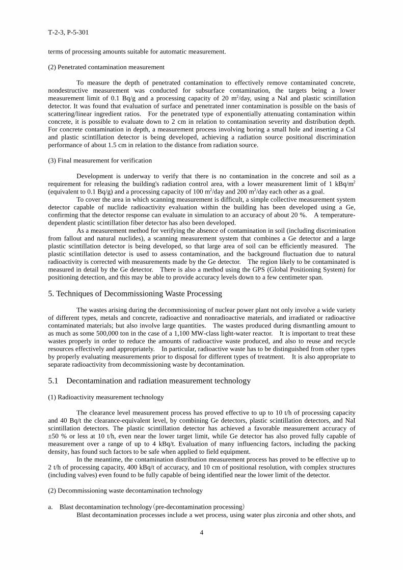
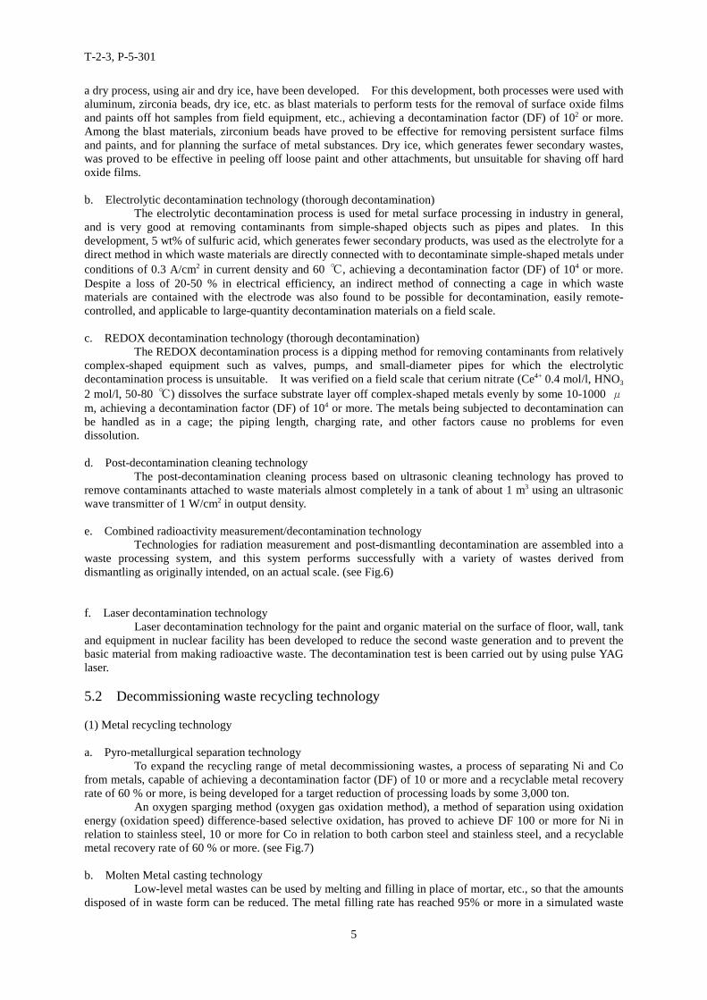
To reduce personnel and environmental burdens, NUPEC has been developing the technologyensuring the safe, reliable, and rational decommissioning of commercial nuclear power plants since 1982 (seeFig.1, 2). Developed technologies will be applied Tokai Power Station (GCR), and also will be applied to thelight water reactors (BWR and PWR) in the next stage. To achieve these purposes, NUPEC has focused itsdevelopment effort on techniques for decontamination, reactor dismantling, measurement of residualradioactivity in buildings and waste, waste recycling and decommissioning engineering.
To achieve a preliminary reduction in the work-atmosphere dose-equivalent rate during dismantlingwork, Techniques for Radiation Exposure Reduction before Dismantling has been developed and DF 100 ormore has been proved possible, and waste decontamination liquid processing technology and decontaminationeffect measurement technology have been developed at the same time.
To ensure safety and minimizing dose rate of workers, mitigate impacts on the surroundingenvironment, the safety protection technology and remote dismantling technology have been developed.
It is necessary to verify that the concentration of radioactive substances remaining on the building’ssurface are below the limit in order to lift the radiation control area and dismantle the building. The wide-areacontamination measuring technique, penetrated contamination measurement and final verification measurementtechnique have been developed. The proposed clearance level has been achieved.
The purpose of Decommissioning Waste Treatment Techniques is to reduce the amounts of radioactivewaste and to reduce environmental burden. The physical and chemical decontamination techniques and thedevelopment of metal and concrete waste recycling techniques are under progress, and some techniques are quitepromising for actual application, and clearance level measurement techniques have been developed, and proto-type actual plant apparatus is probed to have proper performance.
2. Techniques for radiation exposure reduction before dismantling
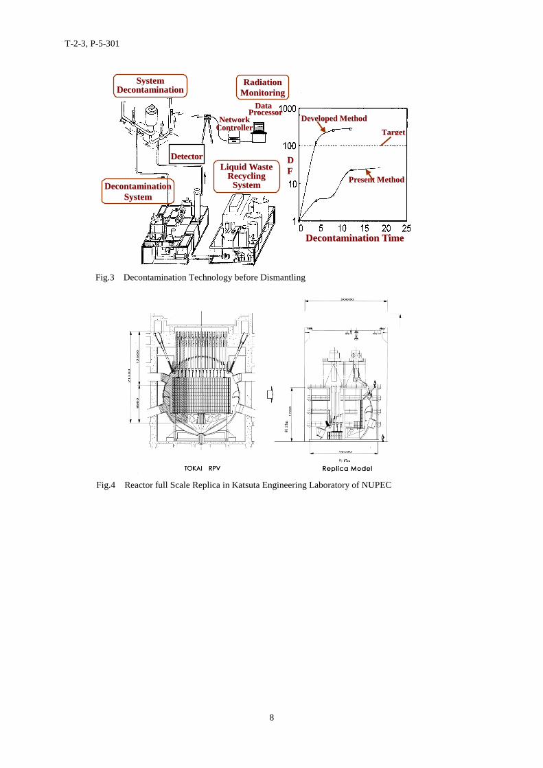
At nuclear power plants, activated iron rust and other substances are deposited on the inner surfaces ofpiping and equipment. To achieve a preliminary reduction in the work-atmosphere dose-equivalent rate duringthe dismantling work -- reducing the dose equivalent for workers and increasing efficiency -- technology is beingdeveloped on a "system decontamination" process for removing contaminants from piping systems, and an"equipment decontamination" process for removing contaminants from large machinery, tanks, and otherequipment using a small amount of decontamination agent. A process for treating the waste liquids derivedfrom decontamination and radiation measurement technology is developed, including rational measurement ofdecontamination effects. (see Fig.3)
(1) Decontamination technology
Decontamination for decommissioning purposes, unlike that during operation, is not restricted byconsiderations of damage to the base material of an item subject to decontamination. To respond to a variety ofcontamination situations, development efforts are aiming to achieve a decontamination agent with adecontamination factor of around 100 that generates less secondary waste and is easy to handle. Among themany decontamination agents available, it is difficult for dilute solution-based chelate, chelate organic acids(including CANDECON), organic acids (including CORD), and metallic ion reduction (LOMI) to achieve alevel of DF 100, while concentrated solution-based organic acids (including oxalic acid) and inorganic acids(including chloric acid and nitric acid) can achieve a level of DF 100, but generate secondary wastes in amountsseveral times larger than the dilute solution-based agents. Efforts to improve decontamination agents areaiming to achieve better decontamination performance with dilute solutions and reduced secondary wastes withconcentrated solution-based agents. These developments involve tests using decontamination skids for oxidefilms prepared on the surfaces of piping, valves, pumps, heat exchangers and other test subjects simulating fieldequipment and under field conditions, and/or with hot sample-based verification of the decontaminationperformance of decontamination agents that are under development.
T-2-3, P-5-301
2
a. System decontaminationThe BWR systems, consisting of stainless steel and carbon steel, have proved capable of achieving DF
100 or more with a circulation process (95 ℃, NP-treated) using a dilute chloric acid reduction agent ofinhibitor-laced chloric acid and vanadium chloride mixtures. Systems in which the circulation method cannot beused have a fill & drain process, using a concentrated chloric acid reduction agent (60 ℃) of chloric acid withvanadium chloride and L-ascorbic acid are added. DF 100 or more has proved possible with the PWR'sprimary-system stainless steel using a circulation process (95 ℃, NP-treated) with oxalic acid and vanadiumoxalate.
b. Large-scale equipment decontaminationLarge-scale equipment has a larger capacity for its decontamination area and, if the equipment is filled
with a decontamination solution, waste decontamination liquids are generated in large quantities. To avoid this,a decontamination performance (DF 45) was verified with a gel process, applying a concentrated chloric acidreduction based decontamination agent or a concentrated organic acid-based decontamination agent to the innersurfaces of tanks and other large containers.
(2) Waste decontamination liquid processing technology
For the smaller amounts of secondary waste generated due to decontamination, technology is beingdeveloped to process waste decontamination liquids so that their renewal/reuse rate can be increased to 70 % ormore, and to dispose of chelate and other organic substance.
It has been shown that chelate decomposition in the waste decontamination liquid with peroxidehydrogen is 90 % or more, while the organic decomposition in waste liquids containing organic substance(inhibitors) is 50 % or more.
Chloric acid-based decontamination agents have proved to achieve a chloric acid recovery rate of70 % or more using an iron exchange-electrolytic renewal method, and a recovery rate of 90 % or more for metalsource ingredients in dilute chloric acid.
(3) Decontamination effect measurement technology
In planning overall decommissioning measures and evaluating work during dismantling operations, itis indispensable to know radioactivity inventories and surface dose-equivalent rates for equipment, etc. aftershutdown. On the other hand, nuclear reactors and primary-system equipment, to which access is difficult dueto high dose-equivalent rates, require remote measurements or fewer access for measurement.
In order to carry out fieldwork in as short a time as possible for the measurement of dose-equivalentrates on equipment surfaces, a measurement system capable of evaluation with fewer measurement points bymeans of an EM (expectation maximization) process is now in use, and data compensation in the CT field isunder development, using small semiconductor detectors that have a light transmission function and wirelessinfrared transmission of measurement data between detectors.
Efforts are being directed at developing a technology for measuring radioactivity on the inner surfacesof pipes using remote detector quantification of radioactivity and identifying waste decontamination liquidradioactivity using the ratio between a γ-ray spectral scattering beam and non-scattering beam counting rates.
3. Dismantling technology
During dismantling the nuclear power plant, it is important to ensure safety and keep to minimumdose rate of workers, mitigate impacts on the surrounding environment, reduce the volume of wastes, andimprove the working efficiency.
(1) Remote operating/automatic control technology
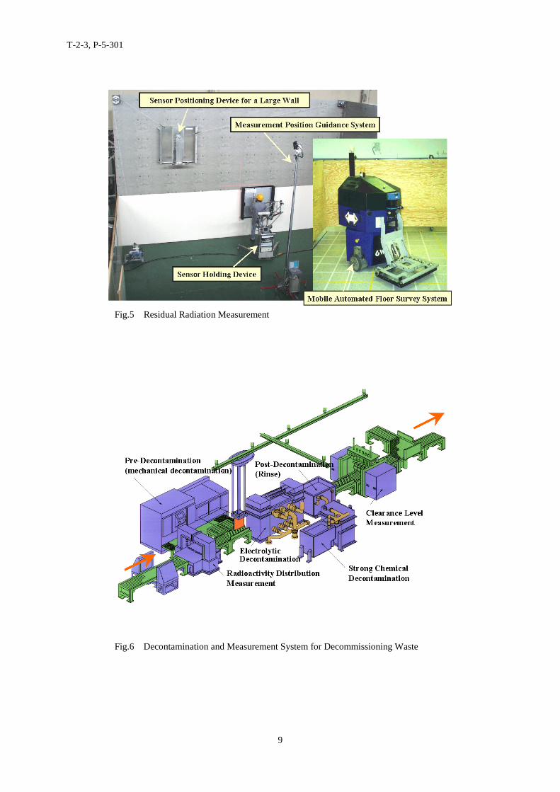
For keeping safe operation under high-radioactive environments, remote operation technique,monitoring system to keep the accuracy and efficiency on the works, and a technique to organically controlelement technologies and ensure reliable automatic control technique for improving the efficiency are underinvestigating by using full scale replica of reactor pressure vessel. (see Fig.4)
(2) Reactor core internal cutting technology
Core internal are made of stainless steel and activated heavy structural member materials. The platethickness is mostly 50-150 mm but some parts in PWR have the thickness of 500 mm. Some tools for cutting
T-2-3, P-5-301
3
location and angle, etc. allow substantial plate of up to 200 mm to be cut, however our target of cutting thicknesswas established 300 mm.
Methods of cutting stainless steel include mechanical cutting and thermal cutting, though laser cuttingmethod, which is surpass in ability of cutting and remote control, were implemented using 30 kW class CO laser.
To reduce the volume of secondary products, laser beam and assist gas conditions to deliver therequired cutting quality with narrower cutting kerf were identified. The reliability and applicability of thereconditions for field equipment of a high-quality cutting process with a special laser cutting nozzle and anothercutting process where a simulated model of core internals is cut, were verified and found to generate fewersecondary products up to 300 mm thickness in air and 150mm under water.
(3) Reactor pressure vessel cutting technique
A reactor pressure vessel is a large component made of 170-420 mm-thick low-carbon alloy plate steelwith stainless steel cladding up to 10 mm thickness. It is activated due to long term operation. Duringdismantling for decommissioning, therefore, due to the necessity of remote operating for cutting under water toreduce the dose rate during works, a combined arc gauzing and gas cutting method was verified. This processfirst fuses off by arc gauzing the cladding of stainless steel having high fusion temperature, allowing the low-alloy steel to be exposed, and then cuts the low-alloy steel by fusion with a propane-oxygen mixture gas using agas cutting torch.
It was verified that a reactor pressure vessel-simulated model (maximum plate thickness of 420 mm)could be cut under water by remote operating and is thus applicable to field equipment.
(4) Biological shield wall surface layer dismantling technique
The biological shield wall is a concrete structure of up to 3 m thickness lined with 10 cm steel plateand densely packed inside with reinforced bar of 51 mm in maximum diameter and activated to its depth ofabout 1m from the inner surface. To separate the surface layer, a process combining cutting with a disk cutterand separation by a wedge process was verified.
Using the 110 MWe-class reactor biological shield wall-simulated model, the inner wall’s steel linerand reinforced concrete were cut horizontally using a disk cutter and then vertically but slightly diagonally intwo directions to verify the separation of a prism-like block. The second layer was separated into the thick-diameter reinforcement part in the vertical direction by the same process. The third layer concrete block wascut vertically and horizontally with a disk cutter and then, using a mechanical wedge, a cubic block wasseparated, confirming the applicability of the technique to field equipment.
4. Residual Radioactivity Measurement and Assessment Techniques for Building and Soil
After equipment has been removed, it is planned to release the radiation control area and dismantle thebuilding. To release the control area, it is necessary to verify that the concentration of radioactive substancesremaining on the building's surfaces is less than the value specified. When the clearance level now under reviewis fixed, it will be necessary to confirm precisely the clearance level. The Co-60 level (0.4 Bq/g) currently beingproposed by the Nuclear Safety Committee is similar to the level for K-40, a typical natural radioactive nuclidecontained in the building's concrete material. For this reason, the measurement technique for radioactivematerials remaining in the building must be able to identify extremely low levels of contaminants contained inthe concrete material precisely, at levels approaching those of K-40.
With this point in mind, technology is being developed for commercial nuclear power plants toevaluate accurately and quickly the positional distribution of residual radioactive contamination on extensivebuilding surfaces of about 100,000 m2, and to assess the extent to which the contamination has penetrated intothe concrete of the building. Detectors and measurement methods are also being developed to verify that nocontamination exists in the building or the soil after the building has been dismantled. (see Fig.5) These testsare being carried out in Tokai Power Station.
(1) Wide-range contamination measuring technique
A collective distribution measurement system is being developed as a technology for accurately andefficiently assessing the distributed state of contamination remaining in building concrete (lower limits formeasurement of the assumed clearance level: 1 kBq/m2, equivalent to 0.1 Bq/g; processing capacity: 100 m2/day).This is based on a γ-ray camera-type 2D distribution detector of NaI, capable of one-time remote measurementat high-elevation locations. Development of a close contact-type measurement system is also underway formeasuring floor surfaces and lower wall, using a plastic scintillation detector that has excellent performance in
T-2-3, P-5-301
4
terms of processing amounts suitable for automatic measurement.
(2) Penetrated contamination measurement
To measure the depth of penetrated contamination to effectively remove contaminated concrete,nondestructive measurement was conducted for subsurface contamination, the targets being a lowermeasurement limit of 0.1 Bq/g and a processing capacity of 20 m2/day, using a NaI and plastic scintillationdetector. It was found that evaluation of surface and penetrated inner contamination is possible on the basis ofscattering/linear ingredient ratios. For the penetrated type of exponentially attenuating contamination withinconcrete, it is possible to evaluate down to 2 cm in relation to contamination severity and distribution depth.For concrete contamination in depth, a measurement process involving boring a small hole and inserting a CsIand plastic scintillation detector is being developed, achieving a radiation source positional discriminationperformance of about 1.5 cm in relation to the distance from radiation source.
(3) Final measurement for verification
Development is underway to verify that there is no contamination in the concrete and soil as arequirement for releasing the building's radiation control area, with a lower measurement limit of 1 kBq/m2
(equivalent to 0.1 Bq/g) and a processing capacity of 100 m2/day and 200 m2/day each other as a goal.To cover the area in which scanning measurement is difficult, a simple collective measurement system
detector capable of nuclide radioactivity evaluation within the building has been developed using a Ge,confirming that the detector response can evaluate in simulation to an accuracy of about 20 %. A temperature-dependent plastic scintillation fiber detector has also been developed.
As a measurement method for verifying the absence of contamination in soil (including discriminationfrom fallout and natural nuclides), a scanning measurement system that combines a Ge detector and a largeplastic scintillation detector is being developed, so that large area of soil can be efficiently measured. Theplastic scintillation detector is used to assess contamination, and the background fluctuation due to naturalradioactivity is corrected with measurements made by the Ge detector. The region likely to be contaminated ismeasured in detail by the Ge detector. There is also a method using the GPS (Global Positioning System) forpositioning detection, and this may be able to provide accuracy levels down to a few centimeter span.
5. Techniques of Decommissioning Waste Processing
The wastes arising during the decommissioning of nuclear power plant not only involve a wide varietyof different types, metals and concrete, radioactive and nonradioactive materials, and irradiated or radioactivecontaminated materials; but also involve large quantities. The wastes produced during dismantling amount toas much as some 500,000 ton in the case of a 1,100 MW-class light-water reactor. It is important to treat thesewastes properly in order to reduce the amounts of radioactive waste produced, and also to reuse and recycleresources effectively and appropriately. In particular, radioactive waste has to be distinguished from other typesby properly evaluating measurements prior to disposal for different types of treatment. It is also appropriate toseparate radioactivity from decommissioning waste by decontamination.
5.1 Decontamination and radiation measurement technology
(1) Radioactivity measurement technology
The clearance level measurement process has proved effective to up to 10 t/h of processing capacityand 40 Bq/t the clearance-equivalent level, by combining Ge detectors, plastic scintillation detectors, and NaIscintillation detectors. The plastic scintillation detector has achieved a favorable measurement accuracy of±50 % or less at 10 t/h, even near the lower target limit, while Ge detector has also proved fully capable ofmeasurement over a range of up to 4 kBq/t. Evaluation of many influencing factors, including the packingdensity, has found such factors to be safe when applied to field equipment.
In the meantime, the contamination distribution measurement process has proved to be effective up to2 t/h of processing capacity, 400 kBq/t of accuracy, and 10 cm of positional resolution, with complex structures(including valves) even found to be fully capable of being identified near the lower limit of the detector.
(2) Decommissioning waste decontamination technology
a. Blast decontamination technology(pre-decontamination processing)Blast decontamination processes include a wet process, using water plus zirconia and other shots, and
T-2-3, P-5-301
5
a dry process, using air and dry ice, have been developed. For this development, both processes were used withaluminum, zirconia beads, dry ice, etc. as blast materials to perform tests for the removal of surface oxide filmsand paints off hot samples from field equipment, etc., achieving a decontamination factor (DF) of 102 or more.Among the blast materials, zirconium beads have proved to be effective for removing persistent surface filmsand paints, and for planning the surface of metal substances. Dry ice, which generates fewer secondary wastes,was proved to be effective in peeling off loose paint and other attachments, but unsuitable for shaving off hardoxide films.
b. Electrolytic decontamination technology (thorough decontamination)The electrolytic decontamination process is used for metal surface processing in industry in general,
and is very good at removing contaminants from simple-shaped objects such as pipes and plates. In thisdevelopment, 5 wt% of sulfuric acid, which generates fewer secondary products, was used as the electrolyte for adirect method in which waste materials are directly connected with to decontaminate simple-shaped metals underconditions of 0.3 A/cm2 in current density and 60 ℃, achieving a decontamination factor (DF) of 104 or more.Despite a loss of 20-50 % in electrical efficiency, an indirect method of connecting a cage in which wastematerials are contained with the electrode was also found to be possible for decontamination, easily remote-controlled, and applicable to large-quantity decontamination materials on a field scale.
c. REDOX decontamination technology (thorough decontamination)The REDOX decontamination process is a dipping method for removing contaminants from relatively
complex-shaped equipment such as valves, pumps, and small-diameter pipes for which the electrolyticdecontamination process is unsuitable. It was verified on a field scale that cerium nitrate (Ce4+ 0.4 mol/l, HNO3
2 mol/l, 50-80 ℃) dissolves the surface substrate layer off complex-shaped metals evenly by some 10-1000 μm, achieving a decontamination factor (DF) of 104 or more. The metals being subjected to decontamination canbe handled as in a cage; the piping length, charging rate, and other factors cause no problems for evendissolution.
d. Post-decontamination cleaning technologyThe post-decontamination cleaning process based on ultrasonic cleaning technology has proved to
remove contaminants attached to waste materials almost completely in a tank of about 1 m3 using an ultrasonicwave transmitter of 1 W/cm2 in output density.
e. Combined radioactivity measurement/decontamination technologyTechnologies for radiation measurement and post-dismantling decontamination are assembled into a
waste processing system, and this system performs successfully with a variety of wastes derived fromdismantling as originally intended, on an actual scale. (see Fig.6)
f. Laser decontamination technologyLaser decontamination technology for the paint and organic material on the surface of floor, wall, tank
and equipment in nuclear facility has been developed to reduce the second waste generation and to prevent thebasic material from making radioactive waste. The decontamination test is been carried out by using pulse YAGlaser.
5.2 Decommissioning waste recycling technology
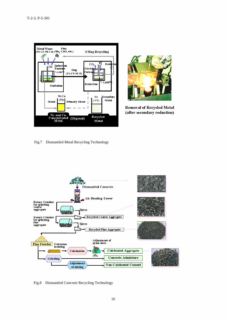
(1) Metal recycling technology
a. Pyro-metallurgical separation technologyTo expand the recycling range of metal decommissioning wastes, a process of separating Ni and Co
from metals, capable of achieving a decontamination factor (DF) of 10 or more and a recyclable metal recoveryrate of 60 % or more, is being developed for a target reduction of processing loads by some 3,000 ton.
An oxygen sparging method (oxygen gas oxidation method), a method of separation using oxidationenergy (oxidation speed) difference-based selective oxidation, has proved to achieve DF 100 or more for Ni inrelation to stainless steel, 10 or more for Co in relation to both carbon steel and stainless steel, and a recyclablemetal recovery rate of 60 % or more. (see Fig.7)
b. Molten Metal casting technologyLow-level metal wastes can be used by melting and filling in place of mortar, etc., so that the amounts
disposed of in waste form can be reduced. The metal filling rate has reached 95% or more in a simulated waste
T-2-3, P-5-301
6
form of 1/2 scale, and the thickness of the container can be reduced to only 6 min.
(2) Concrete recycling technology
a. High-quality aggregate recovery technologyThe objective of this development is to recover coarse and fine aggregates from decommissioning
concrete waste , and to meet the Japan Architecture Society standards JASS5N (standards for nuclear facility).It has been confirmed that the aggregate recovery rate can be raised to 70 % or more to provide a method ofrecycling, making it possible to recycle concrete wastes by some 500,000 ton.
The mechanical grinding method for the recycling of aggregate (a process of removing hydratedconcrete adhering to raw aggregate by grinding it with a crusher) allows recycled coarse aggregate to meet theJASS5N standard. In the case of the selective heating method (a process for renewing aggregate by selectivelyheating cement paste with microwaves for crusher-based separation and removal), both coarse and fineaggregates meet JASS5N. The whole-heating method (a process of grinding with a crusher after whole-heatingtreatment to recover the aggregate) has also enabled both coarse and fine aggregates to satisfy JASS5N. (seeFig.8)
b. By-product powder recycling technologyA process for recovering the powder derived from the high-quality aggregate being recovered into
aggregate, which meets JIS cement standards and JASS5N standards, is being developed in order to recycleconcrete wastes by some 500,000 ton.
It was possible to manufacture Portland cement to JIS standards using a burnt cement manufacturingprocess.
Recycling Technique for Radioactive ConcreteRecycling technology of radioactive concrete into solidification material mortar of waste form is
carried out to establish the production technique for solidifying materials and for sludge filler waste form.
Graphite waste treatment technology
The underground geological disposal of graphite removed from the reactor core was investigated fromthe viewpoint of reduction of underground disposal cost. By cutting a portion of the graphite blocks using amechanical cutting machine such as a band saw and packaging them in waste disposal containers, fundamentaldata was accumulated for the high density storage concept and it was certified that this concept could existrationally.
The incineration disposal of graphite removed from the reactor core was investigated from theviewpoint of reduction of the radioactive material inventory emitted into the atmosphere. A system conceptwas established in which C-14 in the off gas is first separated with isotope in the form of either CO2 or CO, andthen recovered as carbon by deoxidization.
Technical problems that should be cleared in the future for both of these disposal options wereidentified and verification test plans were established. Through execution of various tests based uponestablished verification test plans, we hope to realize safe and rational treatment and disposal of the graphitewaste.
6. Conclusion
In NUPEC the decommissioning technology started in the beginning of 1980’s and the technicaldevelopment on decommissioning waste processing, radiation exposure reduction before dismantling, residualradioactive measurement and assessment for building and soil and dismantling has been carried out. We considerthat the technical development according to the decommissioning state of the research nuclear facilities, nuclearpower plants and so on is necessary for further rational decommissioning.
These technical developments are carried out as MITI’s trust.
T-2-3, P-5-301
7
Fig.2 Decommissioning Technology Development Schedule in NUPEC
FY 82 83 84 85 86 87 88 89 90 91 92 93 94 95 96 97 98 99 0 1 2
Cutting Techniquefor RPV
Taking offTechnique for BSW
Cutting Techniquefor RCI
Waste TreatmentTechnique
DecontaminationTechnique beforeDismantlingResidual RadiationMeasurementTechnique
DismantlingTechnique
RecyclingTechnologyDecontamination & Clearance
Lebel Measurement
Fig.1 Decommissioning Technology Development in NUPEC
(Decommissioning Standard Process) (Technical Development in NUPEC)
T-2-3, P-5-301
8
SSyysstteemmDDeeccoonnttaammiinnaattiioonn
DDeeccoonnttaammiinnaattiioonnSSyysstteemm
DDeetteeccttoorrLLiiqquuiidd WWaassttee
RReeccyycclliinnggSSyysstteemm
NNeettwwoorrkkCCoonnttrroolllleerr
DDaattaa PPrroocceessssoorr
RRaaddiiaattiioonnMMoonniittoorriinngg
DDFF
DDeeccoonnttaammiinnaattiioonn TTiimmee
DDeevveellooppeedd MMeetthhoodd
TTaarrggeett
PPrreesseenntt MMeetthhoodd
Fig.3 Decontamination Technology before Dismantling
Fig.4 Reactor full Scale Replica in Katsuta Engineering Laboratory of NUPEC
T-2-3, P-5-301
9
Fig.5 Residual Radiation Measurement
Fig.6 Decontamination and Measurement System for Decommissioning Waste
T-2-3, P-5-301
10
Fig.7 Dismantled Metal Recycling Technology
Fig.8 Dismantled Concrete Recycling Technology