Embed Size (px)
Citation preview
DEVELOPMENT OF CREEP-RESISTANT, ALUMINA-FORMING FERROUS ALLOYS
FOR HIGH-TEMPERATURE STRUCTURAL USE
Y. Yamamoto, M.P. Brady, G. Muralidharan, B.A. Pint, P.J. Maziasz, D. Shin, B. Shassere
Oak Ridge National Laboratory Oak Ridge, TN, USA
S.S. Babu, C.-H. Kuo University of Tennessee
Knoxville, TN, USA
ABSTRACT
This paper overviews recent advances in developing novel
alloy design concepts of creep-resistant, alumina-forming Fe-
base alloys, including both ferritic and austenitic steels, for
high-temperature structural applications in fossil-fired power
generation systems. Protective, external alumina-scales offer
improved oxidation resistance compared to chromia-scales in
steam-containing environments at elevated temperatures. Alloy
design utilizes computational thermodynamic tools with
compositional guidelines based on experimental results
accumulated in the last decade, along with design and control
of the second-phase precipitates to maximize high-temperature
strengths. The alloys developed to date, including ferritic (Fe-
Cr-Al-Nb-W base) and austenitic (Fe-Cr-Ni-Al-Nb base)
alloys, successfully incorporated the balanced properties of
steam/water vapor-oxidation and/or ash-corrosion resistance
and improved creep strength. Development of cast alumina-
forming austenitic (AFA) stainless steel alloys is also in
progress with successful improvement of higher temperature
capability targeting up to ~1100°C. Current alloy design
approach and developmental efforts with guidance of
computational tools were found to be beneficial for further
development of the new heat resistant steel alloys for various
extreme environments.
INTRODUCTION
Over the past several decades, numerous efforts to develop
structural alloys with improved high-temperature properties
(such as creep strength and/or oxidation resistance) have been
made with the goal of providing acceptably long service lives
in the extreme environments characteristic of fossil-fueled
power generation systems [1,2,3]. Alloy capabilities are sought
that would allow operation at increased temperatures and
pressures to enable improvements in the efficiency of power
generation systems and reduced emissions, and/or their use for
manufacturing heat transfer components with decreased wall
thicknesses, hence improving their ability to withstand thermal
cycling. A major issue to be addressed in the development of
alloys for higher temperatures is the property improvements
balancing the high-temperature mechanical performances and
the environmental compatibilities, since the surface degradation
of materials/components during long-time operation could
shorten the service life less than that expected only from the
material strength. However, the routes for balancing the
strengths and the surface protection in a single alloy often are
mutually incompatible.
To resolve this dilemma, a new alloy design strategy of
“creep-resistant, alumina-forming Fe-base alloys” has been
proposed at Oak Ridge National Laboratory (ORNL), initiated
from alumina-forming austenitic (AFA) stainless steel alloys,
for high-temperature structural applications in fossil-fired
power generation systems [4,5,6,7,8,9,10,11]. Protective,
external alumina-scale exhibits one to two-orders of magnitude
slower oxide growth kinetics compared to chromia-scales, and
is far more stable in water vapor containing environments at
elevated temperatures [12,13], which significantly reduces
potential material failure attributable to surface degradation
during service. The key design strategy is to define
compositional guidelines to achieve protective alumina-scale
formation instead of the chromia-scale formation on
conventional stainless steels, and then maximize second-phase
precipitate strengthening for high temperatures. Computational
thermodynamic tools have been actively utilized for the
downselection of the candidate alloy compositions. The alloy
1 Copyright © 2018 ASME
Proceedings of the ASME 2018 Symposium on Elevated Temperature Application of Materials for Fossil, Nuclear, and Petrochemical Industries
ETAM2018 April 3-5, 2018, Seattle, WA, USA
ETAM2018-6727
Downloaded From: https://proceedings.asmedigitalcollection.asme.org/ on 08/25/2018 Terms of Use: http://www.asme.org/about-asme/terms-of-use

design strategy is applicable to not only austenitic stainless
steels, but also to ferritic steels such as FeCrAl alloys, with
development efforts in progress [14,15].
This paper provides an overview of the recent progress on
developing alumina-forming Fe-base alloys for high-
temperature structural applications at ORNL. The classes of
ferritic and austenitic steel alloys, as well as the recent efforts
on developing cast version of AFA alloys, are s ummarized.
The contents include the detailed alloy design strategies and
property comparison with similar classes of commercially
available steel and alloys.
HIGH CR FECRAL FERRITIC ALLOYS
Alloy Design
FeCrAl alloys are historically known to exhibit very high
oxidation resistance at elevated temperatures because of the
formation of protective, external alumina-scale. Additions of
reactive elements such as Y, Hf, Zr, are also known to improve
the oxidation resistance through reduced oxide growth rate and
enhancing the adhesion between the protective alumina-scale
and the ferrite matrix [16,17]. Such excellent oxidation
resistance at elevated temperatures, especially in water-vapor
containing environments, is also attractive for applications in
various extreme environments, such as accident-tolerant fuel
cladding in light water reactors [18,19,20]. On the other hand,
the high-temperature creep properties of the alloys are poor
because of low creep deformation resistance of the ferritic
matrix with body-center-cubic (BCC) structure [21]. Unlike
ferritic-martensitic steels, FeCrAl alloys consist of a fully
ferritic matrix with no phase-transformation to austenite up to
the melting point. Because of the low carbon solubility in BCC-
Fe matrix, carbides/carbonitrides are not a strong candidate for
precipitate strengthening at elevated temperatures. Oxide
dispersion strengthened (ODS) FeCrAl alloys overcome the
weakness of high-temperature creep property of the alloys [22],
although the production cost (e.g. powder processing,
consolidation, etc.) is higher than conventional cast-and-
wrought processes, and restricts the use of ODS-FeCrAl alloys
to niche applications.
The authors recently proposed a new alloy design with a
base alloy composition of Fe-30Cr-3Al (wt.%) combined with
minor alloy additions of Nb, Zr, Ti, Mo, W, Mn, Si, and C,
which yields a “creep-resistant, high Cr containing FeCrAl
alloys”. The Cr content with ~30 wt.% was selected to improve
ash-corrosion resistance in fire-side corrosive environments
encountered in fossil-fired power plants [23]. The combined
additions of Al and Nb were also found to promote both
steam/water vapor oxidation resistance and ash-corrosion
resistance [14,15]. The alloys were designed with precipitation
strengthening through introduction of Laves phase (C14-
Fe2Nb) precipitate dispersion in BCC-Fe matrix [24]. Similar
approaches to strengthen ferritic steels by Laves phase
precipitates have also been reported [25,26], which
successfully improved creep strength. Computational
thermodynamic tools (JMatPro® v.9 with Fe database and
Thermo-Calc® with TCFE8) were used to guide the alloy
composition range as well as the BCC-solvus temperature to
find solution heat treatment temperature ranges. The
developmental effort initiated from the “model” alloys
consisting of major elements (Fe, Cr, Al, Nb, Si, Ti, Mo, W),
and then moved to the “engineering” alloys containing 0.4Mn,
0.15Si, and 0.03C, simulating typical impurities expected in
industrial scale production
The high Cr containing FeCrAl alloys were designed to
consist of a BCC-Fe single-phase matrix at high temperature
(above the solvus temperature, ~900-1200°C) and BCC-Fe +
Laves phase at low temperature (below solvus temperature),
which allowed fine particle dispersion of Laves phase
precipitates through proper heat treatments. The key factors to
design the alloys are (1) to increase the amount of second-
phase particle dispersions for improved creep resistance, and
(2) lower the solvus temperature as possible (below <1200°C,
ideally ~1100°C) to allow the solution heat treatment at
reasonably low enough temperature to avoid unnecessary grain
coarsening and utilize readily achievable industrial heat
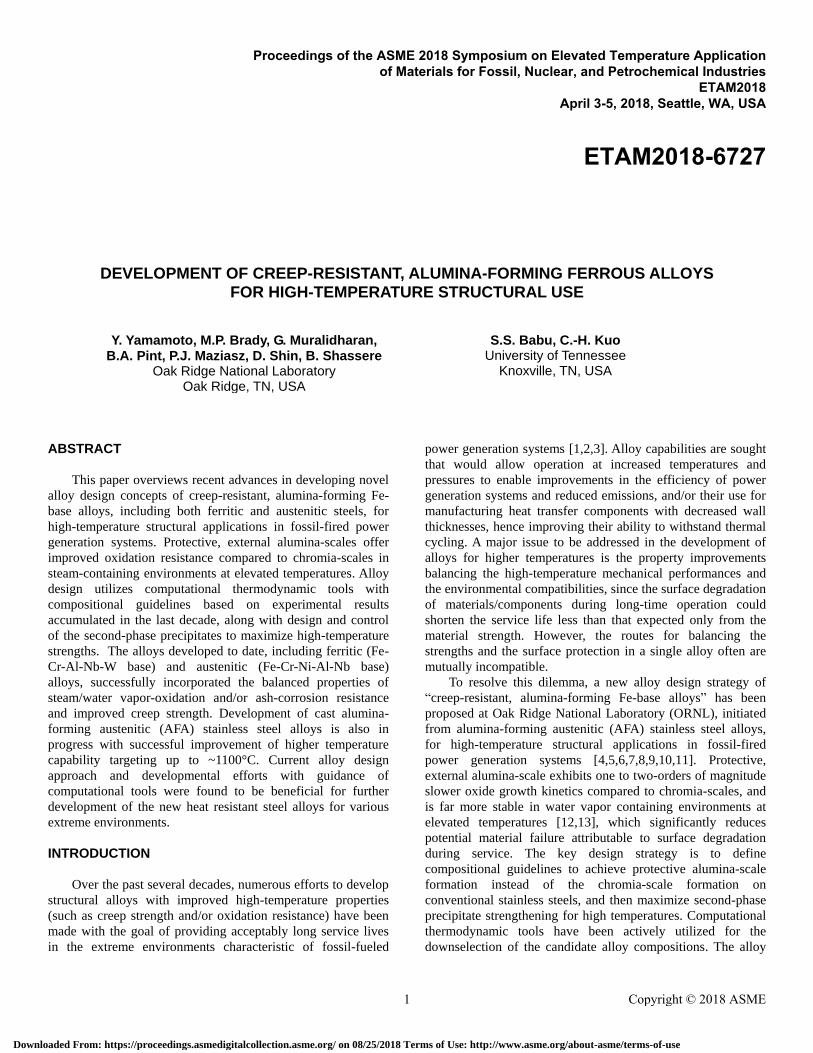
treatment practices. Figure 1 illustrates the calculated amount
of Laves phase at 700°C and the solvus temperatures of the
alloys (based on Fe-30Cr-3Al-1Nb-0.4Mn-0.15Si-0.03C) as a
function of additional Laves-phase forming elements such as
Nb, Ti, Mo, and W. The results demonstrated that both factors
increased with increasing the amount of the additional
elements. The Ti addition exhibited strongest effect on
increasing Laves phase among all elements, and the Nb
addition followed. However, the Nb addition also caused an
abrupt increase of the solvus temperature. The additions of Mo
and W mildly affected to both factors. Note that the amounts of
Ti and Mo additions need to be limited due to poisoning effect
on the stability of protective alumina-scale [5,7,9] and/or
promotion of brittle σ-FeCr or χ-FeCrMo formation [21],
respectively. Based on these considerations, a mixed
combination of 1Nb-(2 or 6)W-0.3Ti-0.5Mo which maximized
the amount of Laves phase at ~700°C range and minimized
potential degradation species were selected and proposed for
further evaluation as one of the candidate alloying additions in
the engineering alloys.
Material Preparation
Lab-scale heats of the model and engineering alloys (~
500g) were prepared by arc-melting with pure element
feedstock, followed by homogenization, hot-forging and -
rolling, and then solution heat treatments, to prepare plate-
shape samples. The alloy composition ranges are summarized
in Table 1. Isothermal tensile creep tests within a range of 650-
800°C and 50-150MPa in laboratory air were conducted by
using a dog bone shape sheet specimen with the gage size of
0.7 x 3.2 x 13 mm. The creep deformation was measured by
using a linear valuable differential transducer attached not to
the specimen but the pulling rod, therefore the tests was
conducted semi-quantitatively. Cyclic oxidation teat at 800°C
2 Copyright © 2018 ASME
Downloaded From: https://proceedings.asmedigitalcollection.asme.org/ on 08/25/2018 Terms of Use: http://www.asme.org/about-asme/terms-of-use
in air +10%H2O and ash-corrosion tests were conducted by
using 0.8 x10 x 20 mm size coupons and 6 mm diameter x 25
mm length rod specimens, respectively. Details of the ash-
corrosion test are summarized in the latter part of this section.
Figure 1. Effects of third element additions on (a) the
calculated mole fraction of Laves-phase at 700°C and (b) the
BCC solvus temperature in Fe-30Cr-3Al-1Nb-0.4Mn-0.15Si-
0.03C base alloys, calculated by JMatPro®.
Table 1. Alloy composition range studied. Model alloys Engineering alloys
Base alloy,
wt.% Fe-30Cr-3Al-0.2Si
Fe-30Cr-3Al-1Nb-
0.4Mn-0.15Si-0.03C-
0.05Y
Alloying
additions,
wt.%
(0, 1, or 2)Nb,
1Nb-(0.1 or 0.3)Zr,
1Nb-(0.5 or 1)Ti, 1Nb-2W
0.5Mo-0.3Ti-2W, 0.5Mo-0.3Ti-6W
Remarks
Also prepared
25Cr-3Al-2Nb alloy &
30Cr-2.6Al-2Nb alloy
Simulating industrial
grade
Creep Performance
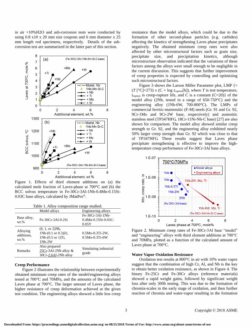
Figure 2 illustrates the relationship between experimentally
obtained minimum creep rates of the model/engineering alloys
tested at 700°C and 70MPa, and the amounts of the calculated
Laves phase at 700°C. The larger amount of Laves phase, the
higher resistance of creep deformation achieved at the given
test condition. The engineering alloys showed a little less creep
resistance than the model alloys, which could be due to the
formation of other second-phase particles (e.g. carbides)
affecting the kinetics of strengthening Laves phase precipitates
negatively. The obtained minimum creep rates were also
affected by other microstructural factors such as grain size,
precipitate size, and precipitation kinetics, although
microstructure observation indicated that the variations of these
factors among the alloys were small enough to be negligible in
the current discussion. This suggests that further improvement
of creep properties is expected by controlling and optimizing
such microstructural factors.
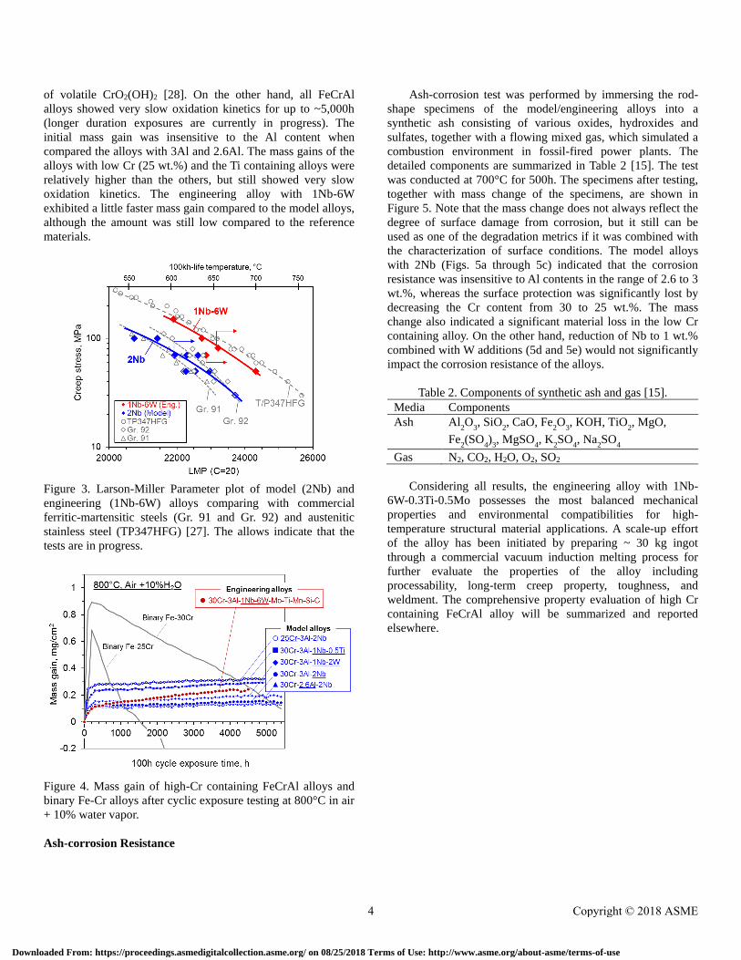
Figure 3 shows the Larson Miller Parameter plot, LMP {=
(T [°C]+273) x (C + log trupture[h]), where T is test temperature,
trupture is creep-rupture life, and C is a constant (C=20)} of the
model alloy (2Nb, tested in a range of 650-750°C) and the
engineering alloy (1Nb-6W, 700-800°C). The LMPs of
commercial ferritic-martensitic (F-M) steels (Gr. 91 and Gr. 92,
9Cr-1Mo and 9Cr-2W base, respectively) and austenitic
stainless steel (TP347HFG, 18Cr-11Ni-Nb-C base) [27] are also
shown for comparison. The model alloy showed similar creep
strength to Gr. 92, and the engineering alloy exhibited nearly
50% larger creep strength than Gr. 92 which was close to that
of TP347HFG. These results suggest that Laves phase
precipitate strengthening is effective to improve the high-
temperature creep performance of Fe-30Cr-3Al base alloys.
Figure 2. Minimum creep rates of Fe-30Cr-3Al base “model”
and “engineering” alloys with third element additions at 700°C
and 70MPa, plotted as a function of the calculated amount of
Laves phase at 700°C.
Water Vapor Oxidation Resistance
Oxidation test results at 800°C in air with 10% water vapor
suggest that the combination of high Cr, Al, and Nb is the key
to obtain better oxidation resistance, as shown in Figure 4. The
binary Fe-25Cr and Fe-30Cr alloys (reference materials)
showed a rapid weight gains, followed by significant weight
loss after only 300h testing. This was due to the formation of
chromia-scales in the early stage of oxidation, and then further
reaction of chromia and water-vapor resulting in the formation
3 Copyright © 2018 ASME
Downloaded From: https://proceedings.asmedigitalcollection.asme.org/ on 08/25/2018 Terms of Use: http://www.asme.org/about-asme/terms-of-use
of volatile CrO2(OH)2 [28]. On the other hand, all FeCrAl
alloys showed very slow oxidation kinetics for up to ~5,000h
(longer duration exposures are currently in progress). The
initial mass gain was insensitive to the Al content when
compared the alloys with 3Al and 2.6Al. The mass gains of the
alloys with low Cr (25 wt.%) and the Ti containing alloys were
relatively higher than the others, but still showed very slow
oxidation kinetics. The engineering alloy with 1Nb-6W
exhibited a little faster mass gain compared to the model alloys,
although the amount was still low compared to the reference
materials.
Figure 3. Larson-Miller Parameter plot of model (2Nb) and
engineering (1Nb-6W) alloys comparing with commercial
ferritic-martensitic steels (Gr. 91 and Gr. 92) and austenitic
stainless steel (TP347HFG) [27]. The allows indicate that the
tests are in progress.
Figure 4. Mass gain of high-Cr containing FeCrAl alloys and
binary Fe-Cr alloys after cyclic exposure testing at 800°C in air
+ 10% water vapor.
Ash-corrosion Resistance
Ash-corrosion test was performed by immersing the rod-
shape specimens of the model/engineering alloys into a
synthetic ash consisting of various oxides, hydroxides and
sulfates, together with a flowing mixed gas, which simulated a
combustion environment in fossil-fired power plants. The
detailed components are summarized in Table 2 [15]. The test
was conducted at 700°C for 500h. The specimens after testing,
together with mass change of the specimens, are shown in
Figure 5. Note that the mass change does not always reflect the
degree of surface damage from corrosion, but it still can be
used as one of the degradation metrics if it was combined with
the characterization of surface conditions. The model alloys
with 2Nb (Figs. 5a through 5c) indicated that the corrosion
resistance was insensitive to Al contents in the range of 2.6 to 3
wt.%, whereas the surface protection was significantly lost by
decreasing the Cr content from 30 to 25 wt.%. The mass
change also indicated a significant material loss in the low Cr
containing alloy. On the other hand, reduction of Nb to 1 wt.%
combined with W additions (5d and 5e) would not significantly
impact the corrosion resistance of the alloys.
Table 2. Components of synthetic ash and gas [15].
Media Components Ash Al
2O
3, SiO
2, CaO, Fe
2O
3, KOH, TiO
2, MgO,
Fe2(SO
4)
3, MgSO
4, K
2SO
4, Na
2SO
4
Gas N2, CO2, H2O, O2, SO2
Considering all results, the engineering alloy with 1Nb-
6W-0.3Ti-0.5Mo possesses the most balanced mechanical
properties and environmental compatibilities for high-
temperature structural material applications. A scale-up effort
of the alloy has been initiated by preparing ~ 30 kg ingot
through a commercial vacuum induction melting process for
further evaluate the properties of the alloy including
processability, long-term creep property, toughness, and
weldment. The comprehensive property evaluation of high Cr
containing FeCrAl alloy will be summarized and reported
elsewhere.
4 Copyright © 2018 ASME
Downloaded From: https://proceedings.asmedigitalcollection.asme.org/ on 08/25/2018 Terms of Use: http://www.asme.org/about-asme/terms-of-use
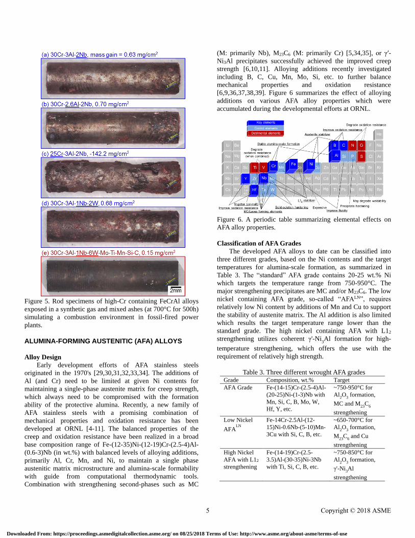
Figure 5. Rod specimens of high-Cr containing FeCrAl alloys
exposed in a synthetic gas and mixed ashes (at 700°C for 500h)
simulating a combustion environment in fossil-fired power
plants.
ALUMINA-FORMING AUSTENITIC (AFA) ALLOYS
Alloy Design
Early development efforts of AFA stainless steels
originated in the 1970's [29,30,31,32,33,34]. The additions of
Al (and Cr) need to be limited at given Ni contents for
maintaining a single-phase austenite matrix for creep strength,
which always need to be compromised with the formation
ability of the protective alumina. Recently, a new family of
AFA stainless steels with a promising combination of
mechanical properties and oxidation resistance has been
developed at ORNL [4-11]. The balanced properties of the
creep and oxidation resistance have been realized in a broad
base composition range of Fe-(12-35)Ni-(12-19)Cr-(2.5-4)Al-
(0.6-3)Nb (in wt.%) with balanced levels of alloying additions,
primarily Al, Cr, Mn, and Ni, to maintain a single phase
austenitic matrix microstructure and alumina-scale formability
with guide from computational thermodynamic tools.
Combination with strengthening second-phases such as MC
(M: primarily Nb), M23C6 (M: primarily Cr) [5,34,35], or γ′-
Ni3Al precipitates successfully achieved the improved creep
strength [6,10,11]. Alloying additions recently investigated
including B, C, Cu, Mn, Mo, Si, etc. to further balance
mechanical properties and oxidation resistance
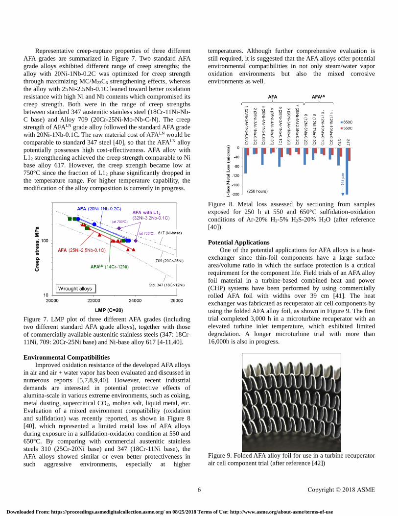
[6,9,36,37,38,39]. Figure 6 summarizes the effect of alloying
additions on various AFA alloy properties which were
accumulated during the developmental efforts at ORNL.
Figure 6. A periodic table summarizing elemental effects on
AFA alloy properties.
Classification of AFA Grades
The developed AFA alloys to date can be classified into
three different grades, based on the Ni contents and the target
temperatures for alumina-scale formation, as summarized in
Table 3. The “standard” AFA grade contains 20-25 wt.% Ni
which targets the temperature range from 750-950°C. The
major strengthening precipitates are MC and/or M23C6. The low
nickel containing AFA grade, so-called “AFALN”, requires
relatively low Ni content by additions of Mn and Cu to support
the stability of austenite matrix. The Al addition is also limited
which results the target temperature range lower than the
standard grade. The high nickel containing AFA with L12
strengthening utilizes coherent γ'-Ni3Al formation for high-
temperature strengthening, which offers the use with the
requirement of relatively high strength.
Table 3. Three different wrought AFA grades Grade Composition, wt.% Target
AFA Grade Fe-(14-15)Cr-(2.5-4)Al-
(20-25)Ni-(1-3)Nb with
Mn, Si, C, B, Mo, W,
Hf, Y, etc.
~750-950°C for
Al2O
3 formation,
MC and M23
C6
strengthening
Low Nickel
AFALN
Fe-14Cr-2.5Al-(12-
15)Ni-0.6Nb-(5-10)Mn-
3Cu with Si, C, B, etc.
~650-700°C for
Al2O
3 formation,
M23
C6 and Cu
strengthening
High Nickel
AFA with L12
strengthening
Fe-(14-19)Cr-(2.5-
3.5)Al-(30-35)Ni-3Nb
with Ti, Si, C, B, etc.
~750-850°C for
Al2O
3 formation,
γ'-Ni3Al
strengthening
5 Copyright © 2018 ASME
Downloaded From: https://proceedings.asmedigitalcollection.asme.org/ on 08/25/2018 Terms of Use: http://www.asme.org/about-asme/terms-of-use
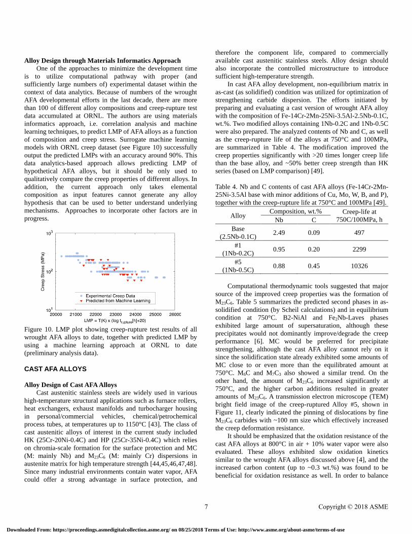
Representative creep-rupture properties of three different
AFA grades are summarized in Figure 7. Two standard AFA
grade alloys exhibited different range of creep strengths; the
alloy with 20Ni-1Nb-0.2C was optimized for creep strength
through maximizing MC/M23C6 strengthening effects, whereas
the alloy with 25Ni-2.5Nb-0.1C leaned toward better oxidation
resistance with high Ni and Nb contents which compromised its
creep strength. Both were in the range of creep strengths
between standard 347 austenitic stainless steel (18Cr-11Ni-Nb-
C base) and Alloy 709 (20Cr-25Ni-Mo-Nb-C-N). The creep
strength of AFALN grade alloy followed the standard AFA grade
with 20Ni-1Nb-0.1C. The raw material cost of AFALN would be
comparable to standard 347 steel [40], so that the AFALN alloy
potentially possesses high cost-effectiveness. AFA alloy with
L12 strengthening achieved the creep strength comparable to Ni
base alloy 617. However, the creep strength became low at
750°C since the fraction of L12 phase significantly dropped in
the temperature range. For higher temperature capability, the
modification of the alloy composition is currently in progress.
Figure 7. LMP plot of three different AFA grades (including
two different standard AFA grade alloys), together with those
of commercially available austenitic stainless steels (347: 18Cr-
11Ni, 709: 20Cr-25Ni base) and Ni-base alloy 617 [4-11,40].
Environmental Compatibilities
Improved oxidation resistance of the developed AFA alloys
in air and air + water vapor has been evaluated and discussed in
numerous reports [5,7,8,9,40]. However, recent industrial
demands are interested in potential protective effects of
alumina-scale in various extreme environments, such as coking,
metal dusting, supercritical CO2, molten salt, liquid metal, etc.
Evaluation of a mixed environment compatibility (oxidation
and sulfidation) was recently reported, as shown in Figure 8
[40], which represented a limited metal loss of AFA alloys
during exposure in a sulfidation-oxidation condition at 550 and
650°C. By comparing with commercial austenitic stainless
steels 310 (25Cr-20Ni base) and 347 (18Cr-11Ni base), the
AFA alloys showed similar or even better protectiveness in
such aggressive environments, especially at higher
temperatures. Although further comprehensive evaluation is
still required, it is suggested that the AFA alloys offer potential
environmental compatibilities in not only steam/water vapor
oxidation environments but also the mixed corrosive
environments as well.
Figure 8. Metal loss assessed by sectioning from samples
exposed for 250 h at 550 and 650°C sulfidation-oxidation
conditions of Ar-20% H2-5% H2S-20% H2O (after reference
[40])
Potential Applications
One of the potential applications for AFA alloys is a heat-
exchanger since thin-foil components have a large surface
area/volume ratio in which the surface protection is a critical
requirement for the component life. Field trials of an AFA alloy
foil material in a turbine-based combined heat and power
(CHP) systems have been performed by using commercially
rolled AFA foil with widths over 39 cm [41]. The heat
exchanger was fabricated as recuperator air cell components by
using the folded AFA alloy foil, as shown in Figure 9. The first
trial completed 3,000 h in a microturbine recuperator with an
elevated turbine inlet temperature, which exhibited limited
degradation. A longer microturbine trial with more than
16,000h is also in progress.
Figure 9. Folded AFA alloy foil for use in a turbine recuperator
air cell component trial (after reference [42])
6 Copyright © 2018 ASME
Downloaded From: https://proceedings.asmedigitalcollection.asme.org/ on 08/25/2018 Terms of Use: http://www.asme.org/about-asme/terms-of-use
Alloy Design through Materials Informatics Approach
One of the approaches to minimize the development time
is to utilize computational pathway with proper (and
sufficiently large numbers of) experimental dataset within the
context of data analytics. Because of numbers of the wrought
AFA developmental efforts in the last decade, there are more
than 100 of different alloy compositions and creep-rupture test
data accumulated at ORNL. The authors are using materials
informatics approach, i.e. correlation analysis and machine
learning techniques, to predict LMP of AFA alloys as a function
of composition and creep stress. Surrogate machine learning
models with ORNL creep dataset (see Figure 10) successfully
output the predicted LMPs with an accuracy around 90%. This
data analytics-based approach allows predicting LMP of
hypothetical AFA alloys, but it should be only used to
qualitatively compare the creep properties of different alloys. In
addition, the current approach only takes elemental
composition as input features cannot generate any alloy
hypothesis that can be used to better understand underlying
mechanisms. Approaches to incorporate other factors are in
progress.
Figure 10. LMP plot showing creep-rupture test results of all
wrought AFA alloys to date, together with predicted LMP by
using a machine learning approach at ORNL to date
(preliminary analysis data).
CAST AFA ALLOYS
Alloy Design of Cast AFA Alloys
Cast austenitic stainless steels are widely used in various
high-temperature structural applications such as furnace rollers,
heat exchangers, exhaust manifolds and turbocharger housing
in personal/commercial vehicles, chemical/petrochemical
process tubes, at temperatures up to 1150°C [43]. The class of
cast austenitic alloys of interest in the current study included
HK (25Cr-20Ni-0.4C) and HP (25Cr-35Ni-0.4C) which relies
on chromia-scale formation for the surface protection and MC
(M: mainly Nb) and M23C6 (M: mainly Cr) dispersions in
austenite matrix for high temperature strength [44,45,46,47,48].
Since many industrial environments contain water vapor, AFA
could offer a strong advantage in surface protection, and
therefore the component life, compared to commercially
available cast austenitic stainless steels. Alloy design should
also incorporate the controlled microstructure to introduce
sufficient high-temperature strength.
In cast AFA alloy development, non-equilibrium matrix in
as-cast (as solidified) condition was utilized for optimization of
strengthening carbide dispersion. The efforts initiated by
preparing and evaluating a cast version of wrought AFA alloy
with the composition of Fe-14Cr-2Mn-25Ni-3.5Al-2.5Nb-0.1C,
wt.%. Two modified alloys containing 1Nb-0.2C and 1Nb-0.5C
were also prepared. The analyzed contents of Nb and C, as well
as the creep-rupture life of the alloys at 750°C and 100MPa,
are summarized in Table 4. The modification improved the
creep properties significantly with >20 times longer creep life
than the base alloy, and ~50% better creep strength than HK
series (based on LMP comparison) [49].
Table 4. Nb and C contents of cast AFA alloys (Fe-14Cr-2Mn-
25Ni-3.5Al base with minor additions of Cu, Mo, W, B, and P),
together with the creep-rupture life at 750°C and 100MPa [49].
Alloy Composition, wt.% Creep-life at
750C/100MPa, h Nb C
Base
(2.5Nb-0.1C) 2.49 0.09 497
#1
(1Nb-0.2C) 0.95 0.20 2299
#5
(1Nb-0.5C) 0.88 0.45 10326
Computational thermodynamic tools suggested that major
source of the improved creep properties was the formation of
M23C6. Table 5 summarizes the predicted second phases in as-
solidified condition (by Scheil calculations) and in equilibrium
condition at 750°C. B2-NiAl and Fe2Nb-Laves phases
exhibited large amount of supersaturation, although these
precipitates would not dominantly improve/degrade the creep
performance [6]. MC would be preferred for precipitate
strengthening, although the cast AFA alloy cannot rely on it
since the solidification state already exhibited some amounts of
MC close to or even more than the equilibrated amount at
750°C. M6C and M7C3 also showed a similar trend. On the
other hand, the amount of M23C6 increased significantly at
750°C, and the higher carbon additions resulted in greater
amounts of M23C6. A transmission electron microscope (TEM)
bright field image of the creep-ruptured Alloy #5, shown in
Figure 11, clearly indicated the pinning of dislocations by fine
M23C6 carbides with ~100 nm size which effectively increased
the creep deformation resistance.
It should be emphasized that the oxidation resistance of the
cast AFA alloys at 800°C in air + 10% water vapor were also
evaluated. These alloys exhibited slow oxidation kinetics
similar to the wrought AFA alloys discussed above [4], and the
increased carbon content (up to ~0.3 wt.%) was found to be
beneficial for oxidation resistance as well. In order to balance
7 Copyright © 2018 ASME
Downloaded From: https://proceedings.asmedigitalcollection.asme.org/ on 08/25/2018 Terms of Use: http://www.asme.org/about-asme/terms-of-use
with the creep performance, the carbon range from 0.3~0.5
wt.% was found to attractive for further development of cast
AFA alloys.
Table 5. Predicted wt.% of phases present after solidification
(Scheil calculations) and equilibrium wt.% (Eq.) of phases in
various cast AFA alloys at 750°C [49]
Alloys Predicted fraction of phases, wt.%
B2-
NiAl
Fe2Nb-
Laves MC M23C6 M6C M7C3
Base
Schei
l 1.5 2.5 0.7 - - -
Eq. 9.2 5.0 0.9 - - -
#1
Schei
l 0.3 - 0.9 - 0.8 -
Eq. 9.9 2.9 0.7 2.8 - -
#5
Schei
l - - 1.0 0.6 1.2 1.4
Eq. 9.5 2.1 0.8 7.0 - -
Figure 11. TEM bright field image of Alloy #5 after creep-
rupture testing at 750°C, 100MPa.
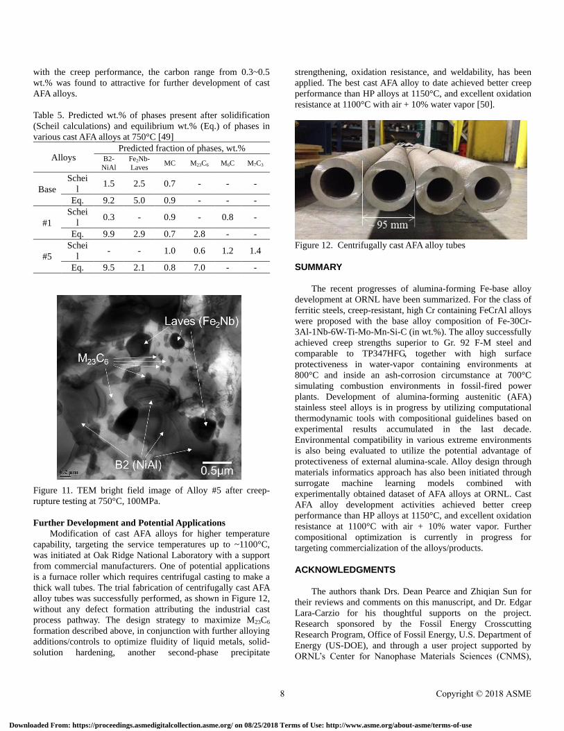
Further Development and Potential Applications
Modification of cast AFA alloys for higher temperature
capability, targeting the service temperatures up to ~1100°C,
was initiated at Oak Ridge National Laboratory with a support
from commercial manufacturers. One of potential applications
is a furnace roller which requires centrifugal casting to make a
thick wall tubes. The trial fabrication of centrifugally cast AFA
alloy tubes was successfully performed, as shown in Figure 12,
without any defect formation attributing the industrial cast
process pathway. The design strategy to maximize M23C6
formation described above, in conjunction with further alloying
additions/controls to optimize fluidity of liquid metals, solid-
solution hardening, another second-phase precipitate
strengthening, oxidation resistance, and weldability, has been
applied. The best cast AFA alloy to date achieved better creep
performance than HP alloys at 1150°C, and excellent oxidation
resistance at 1100°C with air + 10% water vapor [50].
Figure 12. Centrifugally cast AFA alloy tubes
SUMMARY
The recent progresses of alumina-forming Fe-base alloy
development at ORNL have been summarized. For the class of
ferritic steels, creep-resistant, high Cr containing FeCrAl alloys
were proposed with the base alloy composition of Fe-30Cr-
3Al-1Nb-6W-Ti-Mo-Mn-Si-C (in wt.%). The alloy successfully
achieved creep strengths superior to Gr. 92 F-M steel and
comparable to TP347HFG, together with high surface
protectiveness in water-vapor containing environments at
800°C and inside an ash-corrosion circumstance at 700°C
simulating combustion environments in fossil-fired power
plants. Development of alumina-forming austenitic (AFA)
stainless steel alloys is in progress by utilizing computational
thermodynamic tools with compositional guidelines based on
experimental results accumulated in the last decade.
Environmental compatibility in various extreme environments
is also being evaluated to utilize the potential advantage of
protectiveness of external alumina-scale. Alloy design through
materials informatics approach has also been initiated through
surrogate machine learning models combined with
experimentally obtained dataset of AFA alloys at ORNL. Cast
AFA alloy development activities achieved better creep
performance than HP alloys at 1150°C, and excellent oxidation
resistance at 1100°C with air + 10% water vapor. Further
compositional optimization is currently in progress for
targeting commercialization of the alloys/products.
ACKNOWLEDGMENTS
The authors thank Drs. Dean Pearce and Zhiqian Sun for
their reviews and comments on this manuscript, and Dr. Edgar
Lara-Carzio for his thoughtful supports on the project.
Research sponsored by the Fossil Energy Crosscutting
Research Program, Office of Fossil Energy, U.S. Department of
Energy (US-DOE), and through a user project supported by
ORNL’s Center for Nanophase Materials Sciences (CNMS),
8 Copyright © 2018 ASME
Downloaded From: https://proceedings.asmedigitalcollection.asme.org/ on 08/25/2018 Terms of Use: http://www.asme.org/about-asme/terms-of-use
which is sponsored by the Scientific User Facilities Division,
Office of Basic Energy Sciences, U.S. Department of Energy. A
part of the research is also funded by the Advance
Manufacturing Office (AMO, formerly Industrial Technologies
Program, ITP) under Office of Energy Efficiency and
Renewable Energy (EERE), US-DOE, the Technology
Innovation Program (TIP) under Laboratory Directed Research
and Development Program (LDRD) at ORNL, the Seed Money
Funds under LDRD at ORNL, and Advanced Research Projects
Agency-Energy (ARPA-E) under US-DOE.
This manuscript has been authored by UT-Battelle, LLC
under Contract No. DE-AC05-00OR22725 with the U.S.
Department of Energy. The United States Government retains
and the publisher, by accepting the article for publication,
acknowledges that the United States Government retains a non-
exclusive, paid-up, irrevocable, world-wide license to publish
or reproduce the published form of this manuscript, or allow It
others to do so, for United States Government purposes. The
Department of Energy will provide public access to these
results of federally sponsored research in accordance with the
DOE Public Access Plan (http://energy.gov/downloads/doe-
public-access-plan).
REFERENCES
[1] R. Viswanathan and W. Bakker: J. Mater. Eng. Perf.,
2001, vol. 10, pp. 81–95.
[2] R. Viswanathan and W. Bakker: J. Mater. Eng. Perf.,
2001, vol. 10, pp. 96–101.
[3] R. Viswanathan, R. Purgert, and P. Rawls: Adv. Mater.
Processes, 2008, Aug., pp. 41-45.
[4] M.P. Brady, Y. Yamamoto, M.L. Santella, P.J. Maziasz,
B.A. Pint, and C.T. Liu: JOM, 2008, vol. 60 (7), pp. 12–
18.
[5] Y. Yamamoto, M.P. Brady, Z.P. Lu, P.J. Maziasz, C. Liu,
B.A. Pint, K.L. More, H.M. Meyer, and E.A. Payzant:
Science, 2007, vol. 316 (5823), pp. 433–36.
[6] Y. Yamamoto, M. Brady, M. Santella, H. Bei, P. Maziasz,
B. Pint, Metall. Mater. Trans. A-Phys. Metall. Mater. Sci.
42A (2011) 922–931.
[7] M.P. Brady, Y. Yamamoto, M.L. Santella, and B.A. Pint:
Scripta Mater., 2007, vol. 57 (12), pp. 1117–20.
[8] M.P. Brady, Y. Yamamoto, B.A. Pint, M.L. Santella, P.J.
Maziasz, and L.R. Walker: Mater. Sci. Forum, 2008, vols.
595–598, pp. 725–32.
[9] M.P. Brady, Y. Yamamoto, M.L. Santella, and L.R.
Walker: Oxid. Met., 2009, vol. 72 (5–6), pp. 311–33.
[10] Y. Yamamoto, M. Takeyama, Z.P. Lu, C.T. Liu, N.D.
Evans, P.J. Maziasz, M.P. Brady, Intermetallics 16 (2008)
453–462.15.
[11] Y. Yamamoto, G. Muralidharan, M.P. Brady, Scr. Mater.
69 (2013) 816–819.
[12] E.J. Opila, Mater. Sci. Forum 461–464, 765 (2004).
[13] E.J. Opila, N.S. Jacobson, D.L. Myers, and E.H. Copland,
JOM 58, 22 (2006).
[14] Y. Yamamoto, S.S. Babu, B. Shassere, X. Yu, Proceedings
of 123HiMAT-2015 (2015, Sapporo, Japan), the 123rd
Committee on Heat Resisting Materials and Alloys, Japan
Society for the Promotion of Science, pp.66-69 (2015).
[15 Y. Yamamoto, B.A. Pint, B. Shassere, S.S. Babu,
Advances in Materials Technology for Fossil Power
Plants_Proceedings from the eighth international
conference, Pages 319 – 326 (Oct 2016)
[16] B.A. Pint, J. American Ceramic Society, 86 (2003) 686-
695.
[17] B.A. Pint, Oxidation of Metals, 45 (1995) 1-37.
[18] K.A. Terrani, S.J. Zinkle, L.L. Snead, J. Nucl. Mater 448
(2014) 420-435.
[19] Y. Yamamoto, B.A. Pint, K.A. Terrani, K.G. Field, Y.
Yang, L.L. Snead, J. Nucl. Mater 467 (2015) 703-716.
[20] Z. Sun, P.D. Edmondson, Y. Yamamoto, Acta Mater. 144
(2018) 716-727.
[21] L. Colombier and J. Hochmann: Stainless and Heat
Resisting Steels, St. Martin’s Press, New York, NY, 1968.
[22] F.G. Wilson, B.R. Knott, and C.D. Desforges, Met. Mater.
Trans. A, 9 (2) (1978), pp. 275–282.
[23] B.A. Pint, J.K.Thomson, Materials and Corrosion, 65, 2
(2014) pp. 132-140.
[24] B. Shassere, Y. Yamamoto, S.S. Babu, J. Poplawsky, W.
Guo, Met. Mater. Trans. A, 48 (2017) 4598 – 4614.
[25] Toda, Y., Auchi, M., Sawada, M. K., Kushima, H.,
Kimura, K., Proceedings of the 10th Liège Conference:
Materials for Advanced Power Engineering 2014, B.
Kuhn et al (Eds.), September 2014; pp. 239-247.
[26] Kuhn B., and Talik, M., Proceedings of the 10th Liège
Conference: Materials for Advanced Power Engineering
2014, B. Kuhn et al (Eds.), September 2014; pp. 264-273.
[27] National Institute of Materials and Sciences (NIMS)
creep data sheet,
http://smds.nims.go.jp/creep/index_en.html
[28] P.J. Meschter, E.J. Opila, N.S. Jacobson, Annual Review
of Materials Research, 43 (2013) 559-588.
[29] T. Fujioka, M. Kinugasa, S. Iizumi, S. Teshima, I.
Shimizu, US Patent 3,989,514, Nov 2, 1976.
[30] J.A. McGurty, US Patent 4,086,085, April 25, 1978.
[31 J.C. Pivin, D. Delaunay, C. Roquescarmes, A.M. Huntz, P.
Lacombe, Corrosion Sci.20 (1980) 351–373.
[32] B.A. Pint, R. Peraldi, P.J. Maziasz, Proceedings of High
Temperature Corrosion and Protection of Materials 6, Part
1 and 2, Trans Tech, 461–464 (2004) 815-822.
[33] V. Ramakrishnan, J.A. McGurty, N. Jayaraman, Oxid.
Metals 30 (1988) 185–200.
[34] D.V.V. Satyanarayana, G. Malakondaiah, D.S. Sarma,
Mater. Sci. Eng. A-Struct. Mater. Prop. Microstruct.
Process. 323 (2002) 119–128.
[35] F.H. Stott, G.C. Wood, J. Stringer, Oxid. Metals 44 (1995)
113–145.
[36] X.Q. Xu, X.F. Zhang, G.L. Chen, Z.P. Lu, Mater. Lett. 65
(2011) 3285–3288.
9 Copyright © 2018 ASME
Downloaded From: https://proceedings.asmedigitalcollection.asme.org/ on 08/25/2018 Terms of Use: http://www.asme.org/about-asme/terms-of-use
[37] X.Q. Xu, X.F. Zhang, X.Y. Sun, Z.P. Lu, Oxid. Metals 78
(2012) 349–362.
[38] X.Q. Xu, X.F. Zhang, X.Y. Sun, Z.P. Lu, Corrosion Sci. 65
(2012) 317–321.
[39] M.P. Brady, K. Unocic, M. Lance, M. Santella, Y.
Yamamoto, L. Walker, Oxid. Metals 75 (2011) 337–357.
[40] M.P. Brady, J. Magee, Y. Yamamoto, D. Helmick, L.Wang,
Mater. Sci. Eng. A, 590 (2014) 101-115.
[41] B.A. Pint, S. Dryepondt, M.P. Brady, Y. Yamamoto, B.
Ruan, R.D. McKeirnan, Jr., 2015, ASME Paper #GT
2015-42763, presented at the International Gas Turbine &
Aeroengine Congress & Exhibition, Montreal, Canada,
June 15-19, 2015.
[42] B.A. Pint, S. Dryepondt, M.P. Brady, Y. Yamamoto, 2013,
ASME Paper #GT2013-94940, presented at the
International Gas Turbine & Aeroengine Congress &
Exhibition, San Antonio, TX, June, 3-7, 2013.
[43] Steel Castings Handbook, Supplement 9, High Alloy Data
Sheets: Heat Series (Crystal Lake, IL: Steel Founders’
Society of America, 2004), pp. 2–60.
[44] H. Wen-Tai and R.W.K. Honeycombe, Mater. Sci.
Technol. Ser. 1, 385 (1985).
[45] G.D. Barbabela, L.H. de Almeida, T.L. da Silveira, and I.
Le May, Mater. Charact. 26, 1 (1991).
[46] C.W. Thomas, M. Borshevsky, and A.N. Marshall, Mater.
Sci. Technol. Ser. 8, 390 (1992).
[47] R.A.P. Ibanez, G.D. de Almeida Soares, L.H. de Almeida,
and I. Le May, Mater. Charact. 30, 243 (1993).
[48] I.A. Sustaita-Torres, S. Haro-Rodriguez, M.P. Guerrero-
Mata, M. de La Garza, E. Valdes, F. Deshcaux-Beaume,
and R. Colas, Mater. Chem. Phys. 133, 1018 (2012).
[49] G. Muralidharan, Y. Yamamoto, M.P. Brady, L.R. Walker,
H.M. Meyer III, D.N. Leonard, JOM, 68 (2016) 2803-
2810.
[50] M.P. Brady, G. Muralidharan, Y. Yamamoto, B.A. Pint,
Oxidation of Metals, 87 (2017) 1-10.
10 Copyright © 2018 ASME
Downloaded From: https://proceedings.asmedigitalcollection.asme.org/ on 08/25/2018 Terms of Use: http://www.asme.org/about-asme/terms-of-use


![Effects of SnO2 Addition on the Properties of Alumina ...lerating spinel -forming reactions [8] -[10] . Moreover, SnO 2 was used as a spinel forming agent in fired magnesia bricks](https://img.pdfslide.us/doc/110x75/5e87b5ac745a25285447f2a6/effects-of-sno2-addition-on-the-properties-of-alumina-lerating-spinel-forming.jpg)


![HIGH-TEMPERATURE EXPERIMENTAL ......hardening [4] and power law (Norton) creep is used to model the creep deformation during the dwell period of each forming cycle. Cyclic plasticity](https://img.pdfslide.us/doc/110x75/5fc43384d5073f285b2220ba/high-temperature-experimental-hardening-4-and-power-law-norton-creep.jpg)