Embed Size (px)
Citation preview

Mitsubishi Heavy Industries Technical Review Vol. 49 No. 1 (March 2012) 68
*1 Nagasaki Research & Development Center, Technology & Innovation Headquarters
*2 Manager, Nagasaki Research & Development Center, Technology & Innovation Headquarters
*3 Manager, Turbocharger Engineering Department, General Machinery & Special Vehicles
*4 Turbocharger Engineering Department, General Machinery & Special Vehicles
Development of a Wide-Range Centrifugal Compressor for Automotive Turbochargers
SEIICHI IBARAKI*1 ISAO TOMITA*2
MOTOKI EBISU*3 TAKASHI SHIRAISHI*4
The use of turbochargers has been increasing in response to strengthened automotive
exhaust emission and fuel consumption regulations for global environmental protection. The variable geometry (VG) turbocharger has recently become especially popular, creating a demand for a centrifugal compressor that provides wide and stable operation. The internal flow of a centrifugal compressor is very complicated with three dimensional and unsteady flow phenomena, and the analysis of flow phenomena and expansion of the operational range are difficult problems. Mitsubishi Heavy Industries, Ltd. (MHI) has developed a centrifugal compressor with an operational range wider than that of conventional units, based on experimental and numerical analysis of the complicated flow phenomena, and control of the tip leakage vortices at the impeller blades.
|1. Introduction
With the ongoing movement toward global environmental protection, regulations related to the exhaust emissions and fuel consumption of automobiles are being strengthened. To cope with these requirements, turbochargers provide an effective tool for improving fuel consumption and reducing carbon dioxide emissions, by reducing engine weight and friction loss. Since a turbocharger supplies compressed air to an engine, it can reduce the engine displacement relative to a naturally aspirated engine. Variable geometry (VG) turbochargers, which can control the boost pressure according to engine operating conditions, are becoming increasingly popular, creating a demand for a centrifugal compressor with a wide and stable operational range.
The structure of an automotive turbocharger is illustrated in Figure 1. The turbine, which is rotated by exhaust gas, drives the coaxial compressor impeller. Air is compressed and accelerated by the impeller, and its pressure increases while decelerating in the diffuser. This compressed air is supplied to the engine through the scroll.
When the flow rate of a centrifugal compressor is reduced, surging occurs. This produces an overall system pulsation and leads to an operational limit. To expand the operational range of a centrifugal compressor, it is necessary to lower the flow rate limit at which surging occurs. However, flow phenomena are complex and unsteady near the surging range, and the detailed flow structure in the impeller has been unexplained in the past.1 In this report, we clarify the unsteady flow phenomena near the surging range by measuring pressure fluctuations and using unsteady numerical analysis,2,3 and introduce the new wide-range centrifugal compressor, which was developed on the basis of this analysis.
Mitsubishi Heavy Industries Technical Review Vol. 49 No. 1 (March 2012) 69
Figure 1 Automotive turbocharger
|2. Experiments and the flow analysis technique 2.1 Study subject
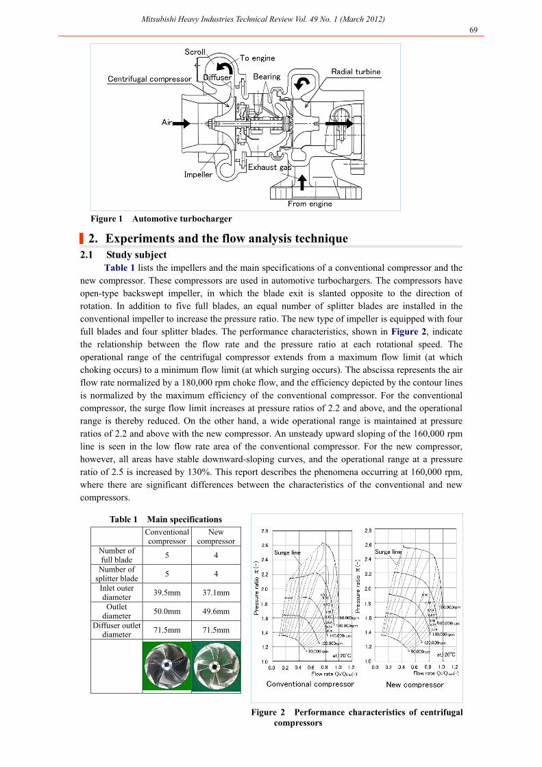
Table 1 lists the impellers and the main specifications of a conventional compressor and the new compressor. These compressors are used in automotive turbochargers. The compressors have open-type backswept impeller, in which the blade exit is slanted opposite to the direction of rotation. In addition to five full blades, an equal number of splitter blades are installed in the conventional impeller to increase the pressure ratio. The new type of impeller is equipped with four full blades and four splitter blades. The performance characteristics, shown in Figure 2, indicate the relationship between the flow rate and the pressure ratio at each rotational speed. The operational range of the centrifugal compressor extends from a maximum flow limit (at which choking occurs) to a minimum flow limit (at which surging occurs). The abscissa represents the air flow rate normalized by a 180,000 rpm choke flow, and the efficiency depicted by the contour lines is normalized by the maximum efficiency of the conventional compressor. For the conventional compressor, the surge flow limit increases at pressure ratios of 2.2 and above, and the operational range is thereby reduced. On the other hand, a wide operational range is maintained at pressure ratios of 2.2 and above with the new compressor. An unsteady upward sloping of the 160,000 rpm line is seen in the low flow rate area of the conventional compressor. For the new compressor, however, all areas have stable downward-sloping curves, and the operational range at a pressure ratio of 2.5 is increased by 130%. This report describes the phenomena occurring at 160,000 rpm,where there are significant differences between the characteristics of the conventional and new compressors.
Table 1 Main specifications
Conventional compressor
New compressor
Number of full blade
5 4
Number of splitter blade 5 4
Inlet outer diameter
39.5mm 37.1mm
Outlet diameter
50.0mm 49.6mm
Diffuser outlet diameter 71.5mm 71.5mm
Figure 2 Performance characteristics of centrifugal compressors

Mitsubishi Heavy Industries Technical Review Vol. 49 No. 1 (March 2012) 70
2.2 Technique of measuring pressure fluctuations To investigate the unsteady phenomena, high-response pressure transducers were installed at
positions 3 mm upstream from the impeller and 1.1 times the radius at the periphery of the diffuser, as shown in Figure 3. The transducers were installed at two positions along the circumference, and unstable phenomena were analyzed via the time difference between the disturbances detected in the compressor. The blade passing frequency (BPF: speed N number of blades Z (Hz)) of the pressure fluctuations caused by the passage of full blades and splitter blades is 26.7 kHz in the conventional compressor and 21.6 kHz in the new compressor. Hence, the sampling frequency for the pressure fluctuation measurements was set at 1 MHz, and 35 or more points between the full blades and splitter blades were measured. Near the surging (where the flow phenomena become unstable), the rotating stall phenomenon (in which a separated flow area rotates at a speed lower than that of the impeller) is known to occur. Therefore, to detect this, frequency fluctuations of 3 N (Hz) or lower were selected for a low-pass filter. 2.3 Numerical analysis technique
Computational fluid dynamics (CFD) was conducted to reproduce the unsteady phenomena, and was applied to the entire compressor, including the impeller, diffuser, and scroll. A total of 3.13 million cells (2.47 million for the impeller, 0.41 million for the diffuser, and 0.25 million for the scroll) were used for the computational grid, illustrated in Figure 4. For the CFD analysis, the ANSYS CFX three-dimensional viscous flow analysis code was used. The k-ε model was used for the turbulence model.
Figure 3 Pressure fluctuation measuring positions Figure 4 Computational grid
|3. Clarification and improvement of the stall phenomenon 3.1 Result of pressure fluctuation measurement
Figure 5 shows the results of the pressure fluctuation measurements in the conventional compressor.
Figure 5 (a) shows the results at the peak pressure point. The pressure wave fluctuation of the impeller was plotted over a 0.25 ms interval, corresponding to 0.7 of the impeller rotation. The pressure fluctuation caused by blade passing was clearly detected, and the pressure wave of each blade had the same shape. The waveform in the low-pass filter was plotted over 5 ms, corresponding to 13 rotations of the impeller. At this operating point, low-frequency phenomena such as rotating stall were not detected. In the pressure fluctuation wave of the diffuser, no significant phenomena other than the passing of full blades and splitter blades were observed. Figure 5 (b) shows the pressure fluctuation waves at the small flow rate point. The low-pass filter wave of the impeller exhibited low-frequency instability. Moreover, at the diffuser, pressurefluctuations corresponding to full blades and splitter blade passage were difficult to distinguish, and unstable phenomena were assumed to affect the diffuser.
Figure 6 shows detailed analysis results from the impeller low-pass filter at the small flow rate point. Transducers 1 and 2 were separated by a 30
oangle, and the time interval between the
detection of a low-frequency disturbance at transducer 1 and the detection of the disturbance at transducer 2 was 0.05 ms. The disturbance therefore required 0.05 ms 360
o / 30
o = 0.60 ms to
cover 360o. In the actual measurements, a similar disturbance was detected by transducer 1 after
0.60 ms. The time required for one complete impeller rotation was 0.375 ms. Thus, the rotational speed of the disturbance was approximately 63% of the impeller speed. Moreover, three

Mitsubishi Heavy Industries Technical Review Vol. 49 No. 1 (March 2012) 71
disturbances were simultaneously detected. This phenomenon is the same as a rotating stall with separated flow areas on the impeller blades, and each disturbance was presumed to be a rotating stall cell. However, it differed from a normal rotating stall. Some very unstable behaviors, such as temporal changes from two to four rotating stall cells, were observed.
The pressure fluctuation measurement results for the new compressor are shown in Figure 7. At the peak efficiency point, shown in Figure 7(a), a low-frequency fluctuation was not observed, unlike the case of the conventional compressor. At the small flow rate point, a slight low-frequency fluctuation was observed in the low-pass filter waveform. However, the fluctuation was contained within several rotations, and no significant phenomenon was evident. Also, full blades and splitter blades could be distinguished at the diffuser, and the flow phenomena at the blades were assumed to be uniform.
Figure 5 Results of pressure fluctuation measurements (conventional compressor)
Figure 6 Structure of a rotating stall (conventional impeller)
Figure 7 Results of pressure fluctuation measurements (new compressor)

Mitsubishi Heavy Industries Technical Review Vol. 49 No. 1 (March 2012) 72
3.2 Results of the unsteady flow analysis The unsteady flow analysis was conducted under the same operational conditions as the
pressure fluctuation measurements. Figure 8 compares the calculated and measured results for the pressure ratio. Although the absolute values showed slight differences, the pressure-flow characteristics of the conventional and new compressor were well simulated, and the actual flow was reproduced. Figure 9 shows the three-dimensional vortex structure and stream lines near the blade. The center of the vortex is colored in accordance with the normalized helicity, and +1/-1 indicates a clockwise/anticlockwise longitudinal vortex. The figure shows the generation of a tornado-shaped vortex on the blades of the conventional compressor. Its movement between blades is as follows. The mainstream flow avoids the vortex on the suction surface of the splitter blade, and the attack angle (the difference between the flow angle and the blade angle) becomes large at t = 0.0 ms. Flow separation is observed on the next blade at t = 0.049 ms, and the separated flow rises as a tornado-shaped vortex at t = 0.090 ms. Each vortex moves over the impeller in this way, while the number of vortices changes temporally, as the measurements indicate. This type of vortex is the main generator of a rotating stall cell, and it is thought that the circumferential expansion of these cells with decreasing flow rate is what triggers surging.
Figure 8 Verification of numerical analysis
Figure 9 Internal flow structure (small flow rate point in a conventional compressor)
The internal flow structure of the new compressor is shown in Figure 10. In the new compressor, the leakage flow between the blade tip and the blade casing forms a tip leakage vortex. This type of vortex cannot maintain a longitudinal shape via its own rotation and the adverse pressure gradient in the impeller. Hence, vortex breakdown occurs, and the vortex dissipates in a spiral flow. The dissipated leakage vortex forms a uniform stall layer in the circumferential direction at the blade tip ends. Figure 11 shows an image of the flow structure at the small flow rate point. In the conventional compressor, a rotating stall cell is generated by the tornado-shaped vortex and its accompanying stall area. In the new compressor, the flow is stabilized by creating a uniform thin stall area at the tip of the blades, and this is accomplished by controlling the local tip leakage vortices. The stall area created by the dissipated leakage flow becomes uniformly thick as the flow rate decreases, and contributes to flow stabilization near the surging range. On the other hand, reduction of efficiency is controlled by eliminating the stall area at the high flow rate operating point.

Mitsubishi Heavy Industries Technical Review Vol. 49 No. 1 (March 2012) 73
Figure 10 Internal flow structure (small flow rate point in a newcompressor)
Figure 11 Images of flow structure
|4. Tasks and future prospects The operating range of the compressor is expanded by controlling the blade-tip leakage
vortices of the impeller. However, factors leading to the occurrence of surging still require clarification, and quantitative prediction of surging is beset by many problems, due to the extreme complexity of the internal flow of a centrifugal compressor. Improved accuracy of numerical analysis will be necessary in the future, and unsteady flow experiments should be conducted to validate the unsteady numerical analysis. Moreover, we would like to further improve the performance of the compressor by optimizing the operating range expansion in terms of devices such as the casing treatment, by realizing a variable compressor, and in other ways.
|5. Conclusion A wide-range centrifugal compressor was developed, based on pressure fluctuation
measurements and unsteady numerical analysis, in order to expand the operational ranges of turbochargers to cope with more stringent exhaust emission and fuel consumption regulations. The new compressor will contribute to improved engine torque by increasing the boost pressure for acceleration at the operational point of a small flow rate. New types of superchargers (such as two-stage turbochargers4 and electric superchargers5,6) are currently being developed for practical application. Improved performance of the compressor (which is one of the fundamental elements) will affect the performance of all types of superchargers. We would like to continue our commitment to improved environmental protection and driving pleasure via improved turbocharger performance.
References
1. Ibaraki, S., Research Trend of Unsteady Flow Phenomena in Centrifugal Compressors, Journal of the Gas Turbine Society of Japan Vol.39 No.2 (2011)
2. Tomita, I. et al., Feature of Internal Flow Phenomena of Centrifugal Compressor for Turbocharger with Wide Operating Range, Gas Turbine Congress 2011.
3. Yamada, K. et al., The Role of Tip Leakage Vortex Breakdown in Flow Fields and Aerodynamic Characteristics of Transonic Centrifugal Compressor Impellers, ASME Paper GT2011-46253
4. An, Byeongil et al., Development of Variable Two-stage Turbocharger for Passenger Car Diesel Engines, Mitsubishi Heavy Industries Technical Review Vol.47 No.4 (2010)
5. Ibaraki, S. et al., Development of the "hybrid turbo," an electrically assisted turbocharger, Mitsubishi Heavy Industries Technical Review Vol.43 No.3 (2006)
6. Yamashita, Y. et al., Development of Electric Supercharger to Facilitate the Downsizing of Automobile Engines, Mitsubishi Heavy Industries Technical Review Vol.47 No.4 (2010)