Embed Size (px)
Citation preview

7/27/2019 Unsteady flow in centrifugal compressor stage
http://slidepdf.com/reader/full/unsteady-flow-in-centrifugal-compressor-stage 1/61
S.Ramamurthy, NCAD, National Aerospace Laboratories, Bangalore-560 017, CSIR
Unsteady Phenomena in Centrifugal compressors-Impeller and Diffuser Interaction 21 July, 2012
Unsteady Phenomena in Centrifugal Compressor
Impeller and Diffuser InteractionBy
S . Ramamurthy

7/27/2019 Unsteady flow in centrifugal compressor stage
http://slidepdf.com/reader/full/unsteady-flow-in-centrifugal-compressor-stage 2/61
S.Ramamurthy, NCAD, National Aerospace Laboratories, Bangalore-560 017, CSIR
Unsteady Phenomena in Centrifugal compressors-Impeller and Diffuser Interaction 21 July, 2012
BASIC CONCEPTS
FLOW, SIGNALS, AVERAGING, SIGNAL-NOISE, CORRELATIONS
COMPRESSOR EVALUATION
TIME AVAERAGE MEASUREMENTS
UNSTADY VELOCITY & PRESSURE MEASUREMENTS
CHARACTERIZATION OF COMPRESSOR EXIT FLOW
JET-WAKE
SLIP FACTORS
EFFICIENCY
SUPERSONIC COMPRESSOR-DIFFUSER
FLOW BEHAVIOUR
FLOW VIDEO
CHARACTERIZATION OF ROTATING STALL & SURGE
STALL FREQUENCY AND STALL CELLS
CHARACTERIZATION OF ROTATING STALL INCEPTION
EARLY WARNING
FLOW VIDEO
CHARCATERIZATION OF SPECTRAL FLCTUATIONS IN CFC
FLOW UNSTAEDYNESS AT IMPELLER EXIT
FREQUENCY OF SPETRAL FLUCTUATIONS

7/27/2019 Unsteady flow in centrifugal compressor stage
http://slidepdf.com/reader/full/unsteady-flow-in-centrifugal-compressor-stage 3/61
CLASSIF ICATION OF FLOW
Uniform flow
I f the flow velocity is the same magni tude and direction at every poin t in the fl uid i t is said to be
uniform.
Non-uniform flow
I f at a given instant, the velocity is not the same at every point the flow is non-un iform.
Steady fl ow
A steady flow is one in which the conditions (veloci ty, pressur e and cross-section) may dif fer from
point to point but DO NOT change with time.
Unsteady flow I f at any point in the fluid, the conditi ons change with time, the flow is descri bed as unsteady.
S.Ramamurthy, NCAD, National Aerospace Laboratories, Bangalore-560 017, CSIR
Unsteady Phenomena in Centrifugal compressors-Impeller and Diffuser Interaction 21 July, 2012

7/27/2019 Unsteady flow in centrifugal compressor stage
http://slidepdf.com/reader/full/unsteady-flow-in-centrifugal-compressor-stage 4/61
Combining the above we can classify any flow in to one of four type:
1. Steady uniform flow
Conditions do not change with position in the stream or with time. Example-flow of water in a pipe of constant diameter at constant velocity
2. Steady non-uniform flow
Conditions change from point to point in the stream but do not change withtime.
Example-flow in a tapering pipe with constant velocity at the inlet - velocity will change
as you move along the length of the pipe toward the exit.
3. Unsteady uniform flow.
At a given instant in time the conditions at every point are the same, but will change with time .
Example-Pipe of constant diameter connected to a pump pumping at a constant rate
which is then switched off.
4. Unsteady non-uniform flow Every condition of the flow may change from point to point and with time at every point.
Example-waves in a channel.
S.Ramamurthy, NCAD, National Aerospace Laboratories, Bangalore-560 017, CSIR
Unsteady Phenomena in Centrifugal compressors-Impeller and Diffuser Interaction 21 July, 2012
7/27/2019 Unsteady flow in centrifugal compressor stage
http://slidepdf.com/reader/full/unsteady-flow-in-centrifugal-compressor-stage 5/61
Ensemble Average
In ensemble average successive sets of data are collected and summed point by point.
A prerequisite for the application of this method is the ability to reproduce the signal asmany times as possible starting always from the same data point.
Repetitive additions of noisy signals tend to emphasize their systematic characteristics and to
cancel out any zero-mean random noise.
If (SNR)o
is the original signal-to-noise ratio of the signal, the final (SNR)f
after N
repetitions (scans) is given by the following equation:
Therefore, by averaging 100 (or 1000) data sets a 10-fold (or a 100-fold) reduction of noiselevel is achieved.
N SNRSNR o f )()(
S.Ramamurthy, NCAD, National Aerospace Laboratories, Bangalore-560 017, CSIR
Unsteady Phenomena in Centrifugal compressors-Impeller and Diffuser Interaction 21 July, 2012

7/27/2019 Unsteady flow in centrifugal compressor stage
http://slidepdf.com/reader/full/unsteady-flow-in-centrifugal-compressor-stage 6/61
x M
s M
z
s z
avg i
i
M
i
i
M
avg avg
1 1
1 1
S.Ramamurthy, NCAD, National Aerospace Laboratories, Bangalore-560 017, CSIR
Unsteady Phenomena in Centrifugal compressors-Impeller and Diffuser Interaction 21 July, 2012

7/27/2019 Unsteady flow in centrifugal compressor stage
http://slidepdf.com/reader/full/unsteady-flow-in-centrifugal-compressor-stage 7/61
The signal to noise ratio: (S/N)
Every measurement is made up of two components.
One component, the signal, carries information about the fluid that is of interest to us.
The second, called noise, is made up of extraneous information that is unwanted because it degrades the
accuracy and precision of an analysis.
Noise free data can never be realized in the laboratory because some types of noise arise from
thermodynamic, quantum and electric effects that are impossible to avoid in measurement.
The signal to noise ratio is a representative marker-is used in describing the quality of an analytical method or
the performance of an instrument.
For a signal, S/N = mean / standard deviation
The average strength of the noise, N, is constant and independent of the magnitude of the signal, S.
The effect of noise on the relative error of a measurement becomes greater and greater as the quantity being
measured decreases in magnitude.
S.Ramamurthy, NCAD, National Aerospace Laboratories, Bangalore-560 017, CSIR
Unsteady Phenomena in Centrifugal compressors-Impeller and Diffuser Interaction 21 July, 2012

7/27/2019 Unsteady flow in centrifugal compressor stage
http://slidepdf.com/reader/full/unsteady-flow-in-centrifugal-compressor-stage 8/61
SOURCES OF NOISE Thermal Noise: Noise that originates from the thermally induced motions in charge carriers is known as
thermal noise.
Chemical : This noise arises from uncontrollable variables in the chemistry of the system such as variationin temperature, pressure, humidity, light and chemical fumes present in the room.
Instrumental : Noise that arises due to the instrumentation itself. It could come from any of the following
components- source, input transducer all signal processing elements, and the output transducer.
This noise has many types and can arise from several sources. There are four main categories of
instrumental noise: Thermal , Shot, Fl icker and Environment al .
Electromagnetic radiation in the environment including ac power lines, radio and TV stations, gasoline
engine ignition systems, arcing switches, brushes in electrical motors, lightening, and ionospheric
disturbances.
S.Ramamurthy, NCAD, National Aerospace Laboratories, Bangalore-560 017, CSIR
Unsteady Phenomena in Centrifugal compressors-Impeller and Diffuser Interaction 21 July, 2012

7/27/2019 Unsteady flow in centrifugal compressor stage
http://slidepdf.com/reader/full/unsteady-flow-in-centrifugal-compressor-stage 9/61
FOURIER TRANSFORMATION
The transformation from the time domain to the
frequency domain is based on forward Fouri er
Transform
S.Ramamurthy, NCAD, National Aerospace Laboratories, Bangalore-560 017, CSIR
Unsteady Phenomena in Centrifugal compressors-Impeller and Diffuser Interaction 21 July, 2012

7/27/2019 Unsteady flow in centrifugal compressor stage
http://slidepdf.com/reader/full/unsteady-flow-in-centrifugal-compressor-stage 10/61
Correlation addresses the question: “to what degree is signal A similar to signal B.”
0 5 10 15 20 250
0.5
1
1.5
Signal A
0 5 10 15 20 25
-2
0
2
Signal B1
0 5 10 15 20 250
0.5
1
1.5Signal B2
Sample
By inspection, A is “correlated” with B2, but B1 is “uncorrelated” with both A and
B2. This is an intuitive and visual definition of “correlation.”
CORRELATION
S.Ramamurthy, NCAD, National Aerospace Laboratories, Bangalore-560 017, CSIR
Unsteady Phenomena in Centrifugal compressors-Impeller and Diffuser Interaction 21 July, 2012
7/27/2019 Unsteady flow in centrifugal compressor stage
http://slidepdf.com/reader/full/unsteady-flow-in-centrifugal-compressor-stage 11/61
0 5 10 15 20 250
0.5
1Original Signal A
0 5 10 15 20 250
0.5
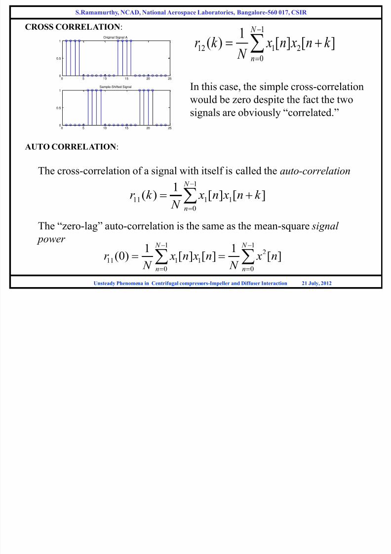
1Sample-Shifted Signal In this case, the simple cross-correlation
would be zero despite the fact the two
signals are obviously “correlated.”
1
12 1 2
0
1( ) [ ] [ ]
N
n
r k x n x n k N
The cross-correlation of a signal with itself is called the auto-correlation
1
0
1111 ][][1
)( N
n
k n xn x
N
k r
The “zero-lag” auto-correlation is the same as the mean-square signal
power 1 1
2
11 1 1
0 0
1 1(0) [ ] [ ] [ ]
N N
n n
r x n x n x n N N
CROSS CORRELATION:
AUTO CORRELATION:
S.Ramamurthy, NCAD, National Aerospace Laboratories, Bangalore-560 017, CSIR
Unsteady Phenomena in Centrifugal compressors-Impeller and Diffuser Interaction 21 July, 2012

7/27/2019 Unsteady flow in centrifugal compressor stage
http://slidepdf.com/reader/full/unsteady-flow-in-centrifugal-compressor-stage 12/61
EXPERIMENTAL EVALUATION OF CF COMPRESSOR
(PERFORMANCE)
S.Ramamurthy, NCAD, National Aerospace Laboratories, Bangalore-560 017, CSIR
Unsteady Phenomena in Centrifugal compressors-Impeller and Diffuser Interaction 21 July, 2012

7/27/2019 Unsteady flow in centrifugal compressor stage
http://slidepdf.com/reader/full/unsteady-flow-in-centrifugal-compressor-stage 13/61
Moderate tip speed
High head back to back
High tip speed
High flow, double flow
Compressor classification
Vane diffuser and volute
Hub wall
shroud wall
S.Ramamurthy, NCAD, National Aerospace Laboratories, Bangalore-560 017, CSIR
Unsteady Phenomena in Centrifugal compressors-Impeller and Diffuser Interaction 21 July, 2012

7/27/2019 Unsteady flow in centrifugal compressor stage
http://slidepdf.com/reader/full/unsteady-flow-in-centrifugal-compressor-stage 14/61
c R
W
dn
dW 2 + Forward Blade
-Backward Blade
S.Ramamurthy, NCAD, National Aerospace Laboratories, Bangalore-560 017, CSIR
Unsteady Phenomena in Centrifugal compressors-Impeller and Diffuser Interaction 21 July, 2012

7/27/2019 Unsteady flow in centrifugal compressor stage
http://slidepdf.com/reader/full/unsteady-flow-in-centrifugal-compressor-stage 15/61
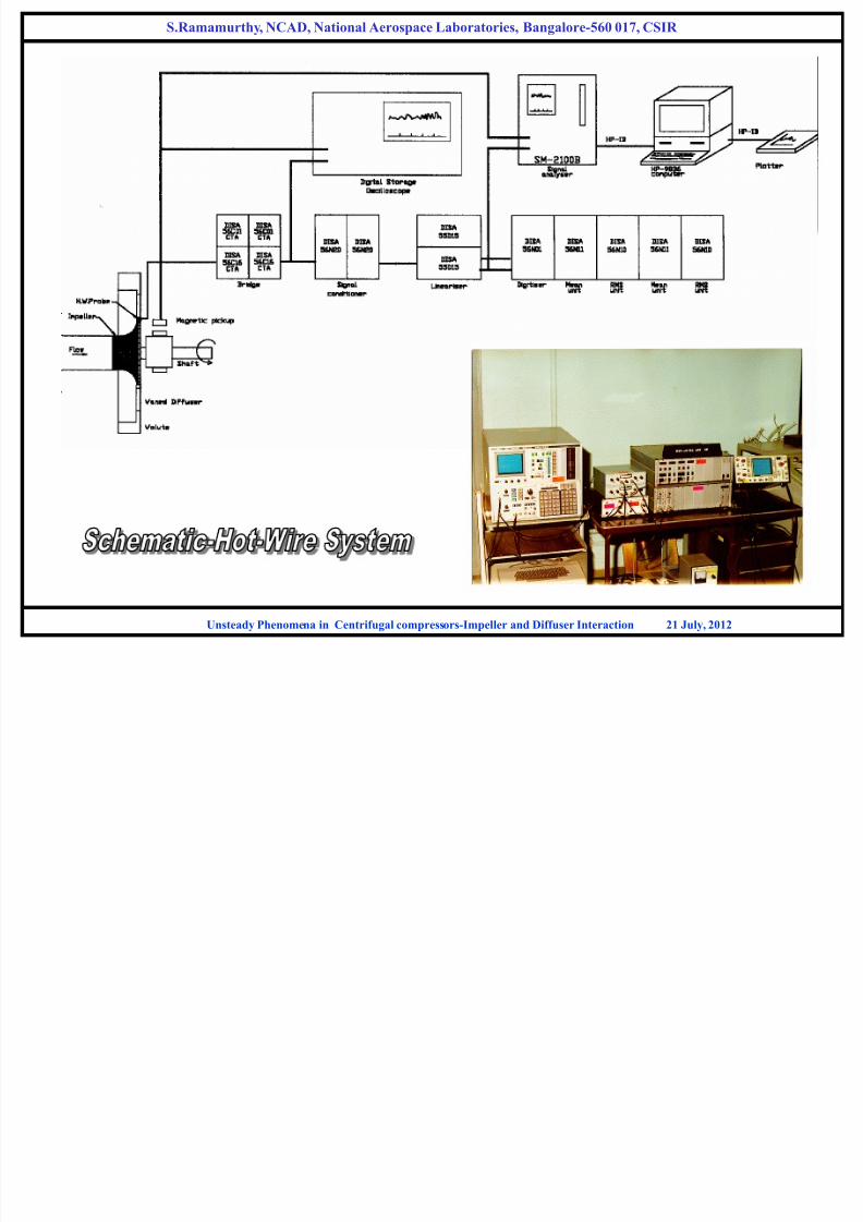
CLOSED CIRCUIT CENTRIFUGAL COMPRESSOR TEST FACILITY INSTRUMENTATION PC based data acquisition system, Electronic torque meter, Hot wire anemometer / FFT analyzer
Accelerometers, Pressure transducers/Thermocouples, Sonic analyzer
Conventional pressure and temperature probes for time averaged measurements- Steady
High response probes for pressure and velocity measurement s- Unsteady
S.Ramamurthy, NCAD, National Aerospace Laboratories, Bangalore-560 017, CSIR
Unsteady Phenomena in Centrifugal compressors-Impeller and Diffuser Interaction 21 July, 2012
7/27/2019 Unsteady flow in centrifugal compressor stage
http://slidepdf.com/reader/full/unsteady-flow-in-centrifugal-compressor-stage 16/61
S.Ramamurthy, NCAD, National Aerospace Laboratories, Bangalore-560 017, CSIR
Unsteady Phenomena in Centrifugal compressors-Impeller and Diffuser Interaction 21 July, 2012
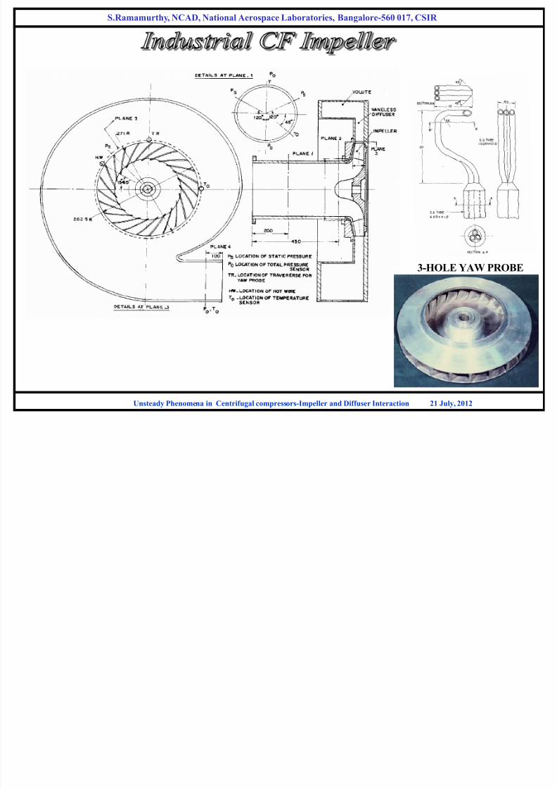
3-HOLE YAW PROBE

7/27/2019 Unsteady flow in centrifugal compressor stage
http://slidepdf.com/reader/full/unsteady-flow-in-centrifugal-compressor-stage 17/61
P
T m
10132501 P
P
15.28801T
T
P
T m
1
1
01
02
1
01
02
T
T
P
P
i
df b
swer measuredPo
P
P
1
1
01
05
65.0)1000/( N b
2.0
2
2
3
20201356.0
en
df R
DU
Line of Zero Incidence
(kg/s) (kg/s)
Line of Zero Incidence
S.Ramamurthy, NCAD, National Aerospace Laboratories, Bangalore-560 017, CSIR
Unsteady Phenomena in Centrifugal compressors-Impeller and Diffuser Interaction 21 July, 2012

7/27/2019 Unsteady flow in centrifugal compressor stage
http://slidepdf.com/reader/full/unsteady-flow-in-centrifugal-compressor-stage 18/61
HEAD-FLOW CHARACTERISTICS
2
2
201
4
U D
m
2
1
2
2
1
01
201
U
P
P T C
S
P
ts
S.Ramamurthy, NCAD, National Aerospace Laboratories, Bangalore-560 017, CSIR
Unsteady Phenomena in Centrifugal compressors-Impeller and Diffuser Interaction 21 July, 2012
POINTS A,B,C ARE CONSIDERED
FOR FURTHER DETAILED
STUDY

7/27/2019 Unsteady flow in centrifugal compressor stage
http://slidepdf.com/reader/full/unsteady-flow-in-centrifugal-compressor-stage 19/61
Axial Width (b/b2) Axial Width (b/b2)
R a d i a l V e l o c
i t y ( m / s )
T a n g e n t i a l V
e l o c i t y ( m / s )
HUB HUB SHROUDSHROUD
Time averaged radial velocity
distribution at impeller outlet
Time averaged tangential velocity
distribution at impeller outlet
S.Ramamurthy, NCAD, National Aerospace Laboratories, Bangalore-560 017, CSIR
Unsteady Phenomena in Centrifugal compressors-Impeller and Diffuser Interaction 21 July, 2012
b2b

7/27/2019 Unsteady flow in centrifugal compressor stage
http://slidepdf.com/reader/full/unsteady-flow-in-centrifugal-compressor-stage 20/61
Axial Width (b/b2) Axial Width (b/b2)
A b s o l u t e f l o w
a n g l e ( d e g . )
R e l a t i v e f l o w a n g l e ( d e g . )
HUB HUBSHROUD SHROUD
Time averaged absolute flow angle
distribution at impeller outlet
Time averaged relative flow angle
distribution at impeller outlet
S.Ramamurthy, NCAD, National Aerospace Laboratories, Bangalore-560 017, CSIR
Unsteady Phenomena in Centrifugal compressors-Impeller and Diffuser Interaction 21 July, 2012

7/27/2019 Unsteady flow in centrifugal compressor stage
http://slidepdf.com/reader/full/unsteady-flow-in-centrifugal-compressor-stage 21/61
OBSERVATIONS ON PERFORMANCE CHARACTERISTICS
Maximum impeller efficiency 90% - Positive incidenceMaximum stage efficiency 75% - Negative incidence
Optimum incidence to impeller may not be the optimum to diffuser
Matching of Impeller with diffuser important
Head flow Characteristics – No Hystericis
S.Ramamurthy, NCAD, National Aerospace Laboratories, Bangalore-560 017, CSIR
Unsteady Phenomena in Centrifugal compressors-Impeller and Diffuser Interaction 21 July, 2012

7/27/2019 Unsteady flow in centrifugal compressor stage
http://slidepdf.com/reader/full/unsteady-flow-in-centrifugal-compressor-stage 22/61
S.Ramamurthy, NCAD, National Aerospace Laboratories, Bangalore-560 017, CSIR
Unsteady Phenomena in Centrifugal compressors-Impeller and Diffuser Interaction 21 July, 2012
KULITE PRESSURE SENSOR MOUNTING
Total pressure Static Pressure
KULITE PRESSURE SENSOR
HOT-WIRE SENSOR
7/27/2019 Unsteady flow in centrifugal compressor stage
http://slidepdf.com/reader/full/unsteady-flow-in-centrifugal-compressor-stage 23/61
S.Ramamurthy, NCAD, National Aerospace Laboratories, Bangalore-560 017, CSIR
Unsteady Phenomena in Centrifugal compressors-Impeller and Diffuser Interaction 21 July, 2012

7/27/2019 Unsteady flow in centrifugal compressor stage
http://slidepdf.com/reader/full/unsteady-flow-in-centrifugal-compressor-stage 24/61
Location of pressure and suction surface trailing edges
q’
S.Ramamurthy, NCAD, National Aerospace Laboratories, Bangalore-560 017, CSIR
Unsteady Phenomena in Centrifugal compressors-Impeller and Diffuser Interaction 21 July, 2012
1. HW senses the absolute flow at 8mm away
from impeller outlet
2. There exists a time diff for the flow to reachthe HW and be sensed, from the point where
it leaves the impeller
3. The time lag is function of location of HW,
magnitude & direction of velocity vector

7/27/2019 Unsteady flow in centrifugal compressor stage
http://slidepdf.com/reader/full/unsteady-flow-in-centrifugal-compressor-stage 25/61
HUB MID SHROUD HUB MID SHROUD
128.0d
094.0d
078.0d
Blade wake
Space averaged(Hot-Wire)
Yaw probe
hubshroud
mid
U2
U2
U2
wake
FlowCoeff.
Near Hub Wall Mid Channel Near Shroud Wall
Yaw
Probe
Hot-
wire
Yaw
Probe
Hot-
wire
Yaw
Probe
Hot-
Wire
0.128 63 65 56 60 49 50
0.094 38 40 36 37 40 50
0.078 29 30 32 33 39 50
FlowCoeff.
Near Hub Wall Mid Channel Near Shroud Wall
Yaw
Probe
Hot-
wire
Yaw
Probe
Hot-
wire
Yaw
Probe
Hot-
wire
0.128 62 60 77 63 77 90
0.094 77 130 83 105 81 110
0.078 67 130 86 113 86 120
S.Ramamurthy, NCAD, National Aerospace Laboratories, Bangalore-560 017, CSIR
Unsteady Phenomena in Centrifugal compressors-Impeller and Diffuser Interaction 21 July, 2012
Absolute Vel
Relative Vel
Blade Speed
Radial Vel

7/27/2019 Unsteady flow in centrifugal compressor stage
http://slidepdf.com/reader/full/unsteady-flow-in-centrifugal-compressor-stage 26/61
Jet flow behaves like potential flow
Relative flow angle don't fit conventional jet-wake model nor 1-D slip theory
Jet-Wake parameters depends on flow coeff
S.Ramamurthy, NCAD, National Aerospace Laboratories, Bangalore-560 017, CSIR
Unsteady Phenomena in Centrifugal compressors-Impeller and Diffuser Interaction 21 July, 2012

7/27/2019 Unsteady flow in centrifugal compressor stage
http://slidepdf.com/reader/full/unsteady-flow-in-centrifugal-compressor-stage 27/61
Blade Wake
Constant
Pressure is higher at SS
Due to higher tangential vel
Pressure not effected by
end wall BL
Higher Energy transfer in wake
Tot. Pr. in jet is constant
Tot. Pr. in wake varies linearlyfrom high vale to low value from
SS
Unstaedy flowLarge variation in angle
Rel. Total Pr. Low
Section F P02
(Kulite)
P02
(Yaw Probe)
% Diff
Hub 0.128
0.094
0.078
1.0558
1.1034
1.1177
1.0726
1.1118
1.1257
1.60
0.80
0.70
Mean 0.128
0.094
0.078
1.0529
1.1119
1.1299
1.0692
1.1117
1.1303
1.50
0.02
0.04
Shroud 0.128
0.094
0.078
1.0619
1.1169
1.1319
1.0757
1.1176
1.1308
1.30
0.70
0.10
S.Ramamurthy, NCAD, National Aerospace Laboratories, Bangalore-560 017, CSIR
Unsteady Phenomena in Centrifugal compressors-Impeller and Diffuser Interaction 21 July, 2012

7/27/2019 Unsteady flow in centrifugal compressor stage
http://slidepdf.com/reader/full/unsteady-flow-in-centrifugal-compressor-stage 28/61
C2
P02
C2
P02
A
B
Static pressure at end walls affected by BL
Shroud side more than hub side
At low flow coeff. Static pr distortion
adjacent to SS
In model Ps decrease from PS to SS
Av. Ps in jet – Isentropic
Present- Ps constant in jet
Cannot be assessed in wake
Approx. increase linearly from SS to
Jet Ps
S.Ramamurthy, NCAD, National Aerospace Laboratories, Bangalore-560 017, CSIR
Unsteady Phenomena in Centrifugal compressors-Impeller and Diffuser Interaction 21 July, 2012
7/27/2019 Unsteady flow in centrifugal compressor stage
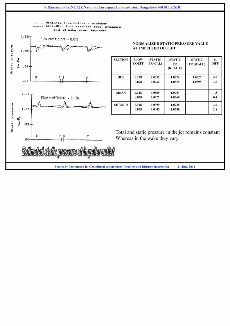
http://slidepdf.com/reader/full/unsteady-flow-in-centrifugal-compressor-stage 29/61
SECTION FLOW
COEFF
STATIC
PR.(CAL)
STATIC
PR.
(KULITE)
STATIC
PR.(WALL)
%
DIFF
HUB 0.128
0.078
1.0352
1.0432
1.0674
1.0855
1.0627
1.0895
3.0
3.8
MEAN 0.128
0.078
1.0559
1.0622
1.0704
1.0669
1.3
0.4
SHROUD 0.128
0.078
1.0399
1.0485
1.0725
1.0789
3.0
2.8
NORMALIZED STATIC PRESSURE VALUE
AT IMPELLER OUTLET
Total and static pressure in the jet remains constant
Whereas in the wake they vary
S.Ramamurthy, NCAD, National Aerospace Laboratories, Bangalore-560 017, CSIR
Unsteady Phenomena in Centrifugal compressors-Impeller and Diffuser Interaction 21 July, 2012

7/27/2019 Unsteady flow in centrifugal compressor stage
http://slidepdf.com/reader/full/unsteady-flow-in-centrifugal-compressor-stage 30/61
c2ww2j W2w
U2
U2
c2j
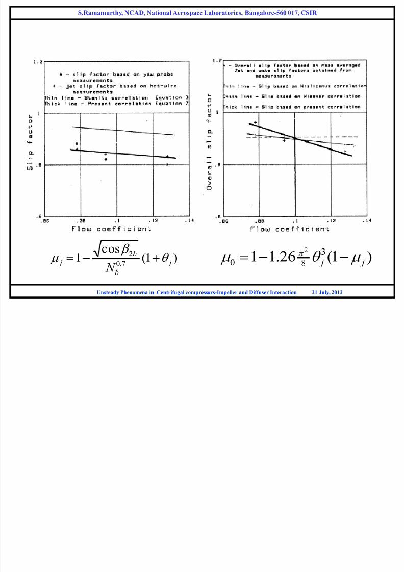
0.85 0.89 0.96 Mass averaged Slip Factor
0.91 1.16 1.18 Wake Slip Factor (Hot wire)
0.88 0.9 0.92 Overall Slip factor (Wislineous)
0.91 0.91 0.91 Slip factor overall (Wisner)
0.92 0.93 0.95 Jet Slip factor (Stanitz)
0.83 0.84 0.86 Jet slip factor (hot wire)
0.8 0.82 0.88 From yaw probe
0.128 0.094 0.078 Flow coefficient
jw )1(0
w
)1(8
1
22
0 j
7.0
2 )cos(1
b
b
N
2/63.01 jq
q
b
cr2
U2
cq2
c2 w2 2b
2
cs
Cs=Slip Velocity
)tan( 2
2
2
2
2b
r
U C
U C q Slip Factor (1 -
CS
U2
S.Ramamurthy, NCAD, National Aerospace Laboratories, Bangalore-560 017, CSIR
Unsteady Phenomena in Centrifugal compressors-Impeller and Diffuser Interaction 21 July, 2012
S R h NCAD N i l A L b i B l 560 017 CSIR
7/27/2019 Unsteady flow in centrifugal compressor stage
http://slidepdf.com/reader/full/unsteady-flow-in-centrifugal-compressor-stage 31/61
)1(cos
17.0
2
j
b
b
j N
q
)1(26.11 3
80
2
j j q
S.Ramamurthy, NCAD, National Aerospace Laboratories, Bangalore-560 017, CSIR
Unsteady Phenomena in Centrifugal compressors-Impeller and Diffuser Interaction 21 July, 2012
S R th NCAD N ti l A L b t i B l 560 017 CSIR

7/27/2019 Unsteady flow in centrifugal compressor stage
http://slidepdf.com/reader/full/unsteady-flow-in-centrifugal-compressor-stage 32/61
Slip Factor depends on flow coefficient
Slip factor increases with decrease in flow coefficient
Jet slip factor is always < 1
Wake slip factor depends on wake width
For large wake width wake slip factor>1 indicating flow angle is less than the blade angle and
specific work is less than Euler work Yaw probe cannot respond to high frequency unsteady flows can measure only average
velocity of jet flow
Variation of slip factor in tangential direction
New correlations – Evaluate wake and jet flow angles
S.Ramamurthy, NCAD, National Aerospace Laboratories, Bangalore-560 017, CSIR
Unsteady Phenomena in Centrifugal compressors-Impeller and Diffuser Interaction 21 July, 2012
S R th NCAD N ti l A L b t i B l 560 017 CSIR

7/27/2019 Unsteady flow in centrifugal compressor stage
http://slidepdf.com/reader/full/unsteady-flow-in-centrifugal-compressor-stage 33/61
FLOW COEFF.= 0.128
FLOW COEFF.= 0.094
FLOW COEFF.= 0.078
Full Line – From hot-wire anemometry measurements
Chain Line- From conceptual jet-wake model
RELATIVE VELOCITY
AT IMPELLER EXIT
jetwake
2b
JET-WAKE MODEL COMPARISION
S.Ramamurthy, NCAD, National Aerospace Laboratories, Bangalore-560 017, CSIR
Unsteady Phenomena in Centrifugal compressors-Impeller and Diffuser Interaction 21 July, 2012
S R th NCAD N ti l A L b t i B l 560 017 CSIR

7/27/2019 Unsteady flow in centrifugal compressor stage
http://slidepdf.com/reader/full/unsteady-flow-in-centrifugal-compressor-stage 34/61
ds
dW
RW
dS
WdW R C
i
/2
Stability of rotating
shear layer
Stability of shear
Layer past curvedwall
C
S R
W R
Richardson Number
Rossby Number
Pressure gradient
Positive away from the surface (SS or
Convex wall) Turbulence intensity
stabilized, Turbulence shear stress
Decreases-BL less resistance to
separation
S.Ramamurthy, NCAD, National Aerospace Laboratories, Bangalore-560 017, CSIR
Unsteady Phenomena in Centrifugal compressors-Impeller and Diffuser Interaction 21 July, 2012
S Ramamurthy NCAD National Aerospace Laboratories Bangalore 560 017 CSIR

7/27/2019 Unsteady flow in centrifugal compressor stage
http://slidepdf.com/reader/full/unsteady-flow-in-centrifugal-compressor-stage 35/61
m
mw
j
w
W W
2
2
2
2
q
q w
Wake mass flow rate
Total mass flow rate
Relative velocity of the wake flow
Relative velocity of the jet flow
Circumferential space occupied by wake
Blade to blade spacing
S.Ramamurthy, NCAD, National Aerospace Laboratories, Bangalore-560 017, CSIR
Unsteady Phenomena in Centrifugal compressors-Impeller and Diffuser Interaction 21 July, 2012
S Ramamurthy NCAD National Aerospace Laboratories Bangalore 560 017 CSIR
7/27/2019 Unsteady flow in centrifugal compressor stage
http://slidepdf.com/reader/full/unsteady-flow-in-centrifugal-compressor-stage 36/61
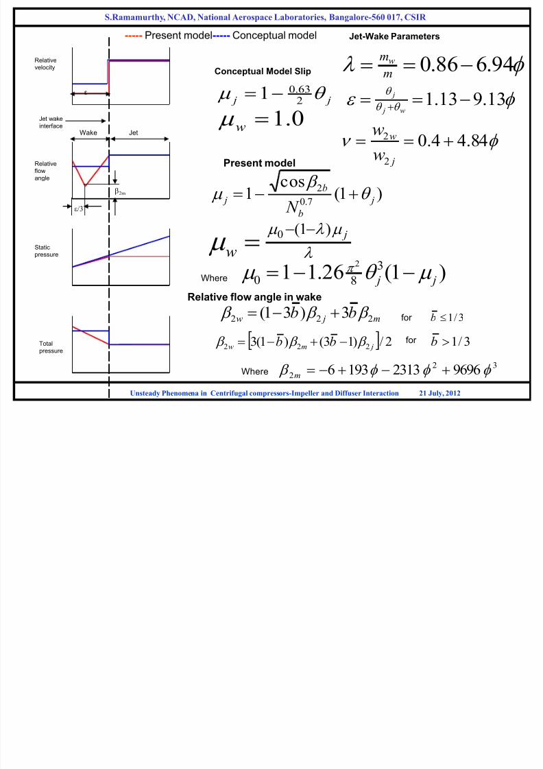
----- Present model----- Conceptual model
Relative
velocity
Relative
flow
angle
Static
pressure
Total
pressure
Jet-Wake Parameters
94.686.0 m
mw
q q
q
13.913.1 w j
j
84.44.02
2 j
w
w
w
Conceptual Model Slip
j j q 2
63.0
10.1w
Present model
)1(cos
1 7.0
2
j
b
b
j N q
j
w
)1(0
Where )1(26.11 3
80
2
j j q Relative flow angle in wake
m jw bb 222 3)31( for 3/1b
2/)13()1(3 222 jmw bb for 3/1b
Where32
2 969623131936 m
Jet wake
interfaceJetWake
ε
/3
2m
S.Ramamurthy, NCAD, National Aerospace Laboratories, Bangalore-560 017, CSIR
Unsteady Phenomena in Centrifugal compressors-Impeller and Diffuser Interaction 21 July, 2012
S Ramamurthy NCAD National Aerospace Laboratories Bangalore 560 017 CSIR
7/27/2019 Unsteady flow in centrifugal compressor stage
http://slidepdf.com/reader/full/unsteady-flow-in-centrifugal-compressor-stage 37/61
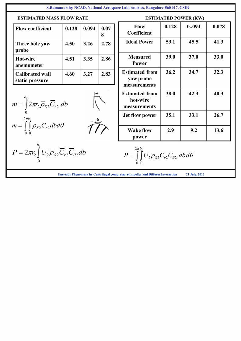
Flow coefficient 0.128 0.094 0.07
8
Three hole yawprobe
4.50 3.26 2.78
Hot-wire
anemometer
4.51 3.35 2.86
Calibrated wall
static pressure
4.60 3.27 2.83
2
0
222 .2
b
r S dbC r m
q
2
0 022
2b
r S dbd C m
ESTIMATED MASS FLOW RATE ESTIMATED POWER (KW)
Flow
Coefficient
0.128 0..094 0.078
Ideal Power 53.1 45.5 41.3
Measured
Power
39.0 37.0 33.0
Estimated from
yaw probe
measurements
36.2 34.7 32.3
Estimated from
hot-wire
measurements
38.0 42.3 40.3
Jet flow power 35.1 33.1 26.7
Wake flow
power
2.9 9.2 13.6
2
0
222222
b
r S dbC C U r P q
q q 2
0 0
2222
2
.. d dbC C U P
b
r S
S.Ramamurthy, NCAD, National Aerospace Laboratories, Bangalore-560 017, CSIR
Unsteady Phenomena in Centrifugal compressors-Impeller and Diffuser Interaction 21 July, 2012
S Ramamurthy NCAD National Aerospace Laboratories Bangalore-560 017 CSIR

7/27/2019 Unsteady flow in centrifugal compressor stage
http://slidepdf.com/reader/full/unsteady-flow-in-centrifugal-compressor-stage 38/61
q
q
2
0
2
0
2
0
2
0
))((
))((
b
r
b
r h
h
dbd C
dbd C
22
1
01
02 1
q
C U
P
P C p
h
and Velocity form hot-wire
Wake flow efficiency is high. At the interface between
Jet – wake the efficiency is low due to large shear
S.Ramamurthy, NCAD, National Aerospace Laboratories, Bangalore-560 017, CSIR
Unsteady Phenomena in Centrifugal compressors-Impeller and Diffuser Interaction 21 July, 2012
S Ramamurthy NCAD National Aerospace Laboratories Bangalore-560 017 CSIR
7/27/2019 Unsteady flow in centrifugal compressor stage
http://slidepdf.com/reader/full/unsteady-flow-in-centrifugal-compressor-stage 39/61
Wake mass flow and wake width depends on flow coefficient
Increases with increase in flow coefficient
Considerable amount of wake mass flow and wake width exists and cannot be
neglected in the off design performance prediction
Wake flow absorbs part of the power from shaft input power and part from jet
power which has undergone slip
Excess power available in the wake is considered as apparent power
Power input within the channel is non-uniform
S.Ramamurthy, NCAD, National Aerospace Laboratories, Bangalore-560 017, CSIR
Unsteady Phenomena in Centrifugal compressors-Impeller and Diffuser Interaction 21 July, 2012
S.Ramamurthy, NCAD, National Aerospace Laboratories, Bangalore-560 017, CSIR

7/27/2019 Unsteady flow in centrifugal compressor stage
http://slidepdf.com/reader/full/unsteady-flow-in-centrifugal-compressor-stage 40/61
Kulite Transducer Terminal
Box 1
Terminal
Box 2
16 Channel
Programmable Gain
Amplifier card
Data Acquisition
Processor Card
Plotter
Differential signal
Differential signal Amplified Single endedsignal
Eddy Current ProbeDriver
Analog to TTL
( transistor transistor logic)
Converter
(-15V to – 10V) (0 to 5V TTL Pulse)
Pentium
Layout of high speed data acquisition processor system.
KULITE PRESSURE TRANSDUCER
S.Ramamurthy, NCAD, National Aerospace Laboratories, Bangalore 560 017, CSIR
Unsteady Phenomena in Centrifugal compressors-Impeller and Diffuser Interaction 21 July, 2012
Supersonic Centrifugal Compressor Stage
S.Ramamurthy, NCAD, National Aerospace Laboratories, Bangalore-560 017, CSIR
7/27/2019 Unsteady flow in centrifugal compressor stage
http://slidepdf.com/reader/full/unsteady-flow-in-centrifugal-compressor-stage 41/61
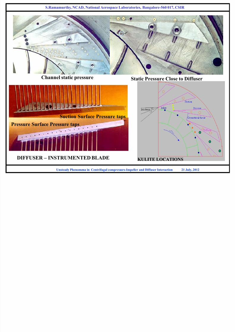
DIFFUSER – INSTRUMENTED BLADE
Channel static pressure Static Pressure Close to Diffuser
Suction Surface Pressure taps
Pressure Surface Pressure taps
KULITE LOCATIONS
S.Ramamurthy, NCAD, National Aerospace Laboratories, Bangalore 560 017, CSIR
Unsteady Phenomena in Centrifugal compressors-Impeller and Diffuser Interaction 21 July, 2012
5 /7S.Ramamurthy, NCAD, National Aer
ospace Laboratories, Bangalore-560 017, CSIR

7/27/2019 Unsteady flow in centrifugal compressor stage
http://slidepdf.com/reader/full/unsteady-flow-in-centrifugal-compressor-stage 42/61
ms
0.0 2.5 5.0 7.5 10.0 12.5 15.
5rc/a7
150
100
50
150
100
50
150
100
50
150
100
50
150
100
50
150
100
50
ms
0.0 2.5 5.0 7.5 10.0 12.5 15.
150
100
50
150
100
50
150
100
50
150
100
50
150
100
50
150
100
50
ms
0.0 2.5 5.0 7.5 10.0 12.5 15.
150
100
50
150
100
50
150
100
50
150
100
50
150
100
50
150
100
50
Impeller outlet
Diffuser leading edge
Diffuser throat
Diffuser channel
Diffuser channel
Diffuser outlet
F.C = 0.038
F.C = 0.031 F.C = 0.023
Circumferential variation of static pressure at different locations along vane diffuser
S.Ramamurthy, NCAD, National Aerospace Laboratories, Bangalore 560 017, CSIR
Unsteady Phenomena in Centrifugal compressors-Impeller and Diffuser Interaction 21 July, 2012
S.Ramamurthy, NCAD, National Aerospace Laboratories, Bangalore-560 017, CSIR

7/27/2019 Unsteady flow in centrifugal compressor stage
http://slidepdf.com/reader/full/unsteady-flow-in-centrifugal-compressor-stage 43/61
ms
0.0 2.5 5.0 7.5 10.0 12.5 15.
ms
0.0 2.5 5.0 7.5 10.0 12.5 15.0
F.C = 0.027
F.C = 0.021
F.C = 0.022
F.C = 0.023
F.C = 0.024
F.C = 0.020
F.C = 0.029
F.C = 0.030
F.C =0.031
F.C = 0.032
F.C = 0.033
F.C = 0.034
F.C = 0.035
F.C = 0.038
F.C = 0.053
Pressure surface Center Suction surface
50
150
ms
0.0 2.5 5.0 7.5 10.0 12.5 15.0
50
150
500
-500
-1000
1000
-7000
7000
1000
-1000
1000
-10003000
-3000
Diffuser throat static pressure variation at different flow coefficients
y, , p , g ,
Unsteady Phenomena in Centrifugal compressors-Impeller and Diffuser Interaction 21 July, 2012
S.Ramamurthy, NCAD, National Aerospace Laboratories, Bangalore-560 017, CSIR

7/27/2019 Unsteady flow in centrifugal compressor stage
http://slidepdf.com/reader/full/unsteady-flow-in-centrifugal-compressor-stage 44/61
ms
0 5 10 15 20 25 30 35 40 45 50 55 60 65
200
150
100
50
0
200
150
100
50
0
200
150
100
50
0
200
150
100
50
0
Circumfrential variation of static pressure at impeller outlet - stalled condition
(Flow coefficient = 0.02)
K1
K2
K3
K4
y, , p , g ,
Unsteady Phenomena in Centrifugal compressors-Impeller and Diffuser Interaction 21 July, 2012

7/27/2019 Unsteady flow in centrifugal compressor stage
http://slidepdf.com/reader/full/unsteady-flow-in-centrifugal-compressor-stage 45/61
S.Ramamurthy, NCAD, National Aerospace Laboratories, Bangalore-560 017, CSIR
7/27/2019 Unsteady flow in centrifugal compressor stage
http://slidepdf.com/reader/full/unsteady-flow-in-centrifugal-compressor-stage 46/61
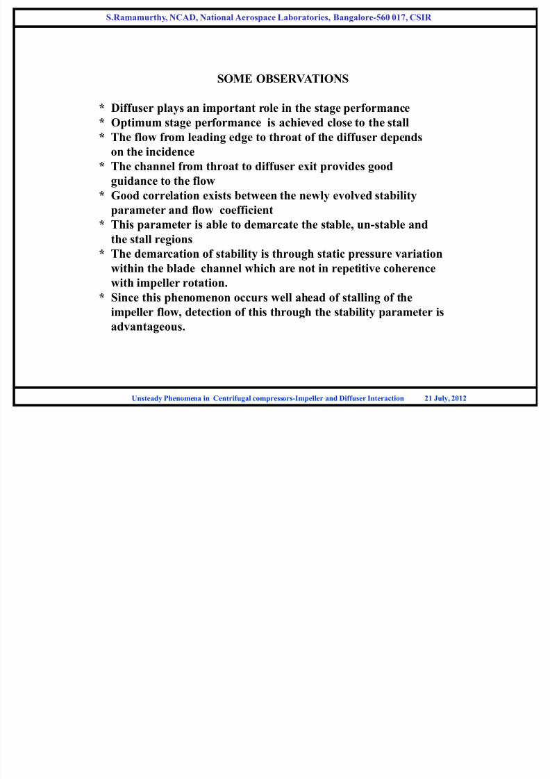
SOME OBSERVATIONS
* Diffuser plays an important role in the stage performance
* Optimum stage performance is achieved close to the stall
* The flow from leading edge to throat of the diffuser depends
on the incidence
* The channel from throat to diffuser exit provides good
guidance to the flow
* Good correlation exists between the newly evolved stabilityparameter and flow coefficient
* This parameter is able to demarcate the stable, un-stable and
the stall regions
* The demarcation of stability is through static pressure variation
within the blade channel which are not in repetitive coherence
with impeller rotation.
* Since this phenomenon occurs well ahead of stalling of the
impeller flow, detection of this through the stability parameter is
advantageous.
y p g
Unsteady Phenomena in Centrifugal compressors-Impeller and Diffuser Interaction 21 July, 2012
S.Ramamurthy, NCAD, National Aerospace Laboratories, Bangalore-560 017, CSIR
7/27/2019 Unsteady flow in centrifugal compressor stage
http://slidepdf.com/reader/full/unsteady-flow-in-centrifugal-compressor-stage 47/61
STALL AND SURGE
Unsteady Phenomena in Centrifugal compressors-Impeller and Diffuser Interaction 21 July, 2012
S.Ramamurthy, NCAD, National Aerospace Laboratories, Bangalore-560 017, CSIR

7/27/2019 Unsteady flow in centrifugal compressor stage
http://slidepdf.com/reader/full/unsteady-flow-in-centrifugal-compressor-stage 48/61
Stall- Flow Separation due to high incidence with reduction CL
Rotating Stall: Non-axisymmetric flow with circumferentially non-uniform pattern rotating around
the annulus
D pD p
m. m m
D p
.
Rotating
stall
Average mass
flow rate
Notaxisymetric
Not axisymetric
Progressiv
Stall
Abrupt
Stall
Surge
Flow
Through flow
Velocity(axial)
Circumferential
velocity
Cell rotation
Instability of Axi-symetric
Very small Very small
Very large Very large
50% 20-40%
Conserved Conserved Varies with time
Effect of stall/surge: Vibrational excitation resulting in Mechanical failure.
Characterization: Stall propagating speed/No. of cells
Detect: Change in noise/high frequency instrumentation.
Time scale: Stall Surge
50-100Hz 3-10Hz
.A
B`
C
Unsteady Phenomena in Centrifugal compressors-Impeller and Diffuser Interaction 21 July, 2012
S.Ramamurthy, NCAD, National Aerospace Laboratories, Bangalore-560 017, CSIR
7/27/2019 Unsteady flow in centrifugal compressor stage
http://slidepdf.com/reader/full/unsteady-flow-in-centrifugal-compressor-stage 49/61
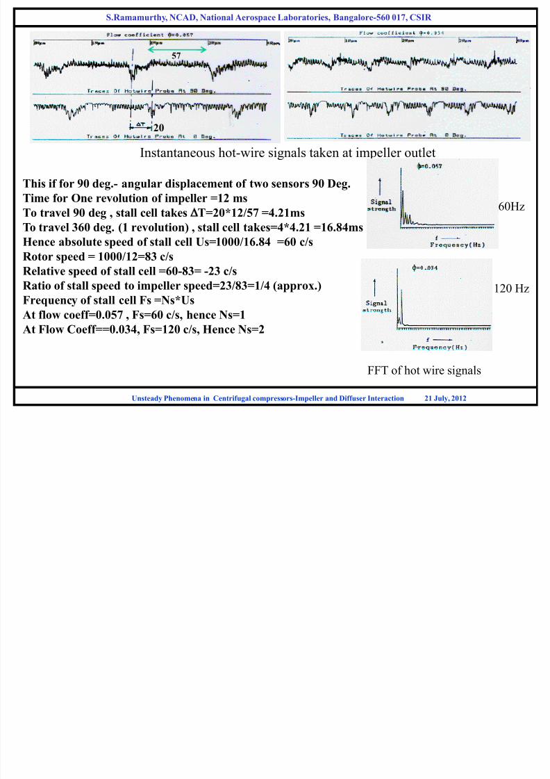
Instantaneous hot-wire signals taken at impeller outlet
Unsteady Phenomena in Centrifugal compressors-Impeller and Diffuser Interaction 21 July, 2012
This if for 90 deg.- angular displacement of two sensors 90 Deg.
Time for One revolution of impeller =12 msTo travel 90 deg , stall cell takes DT=20*12/57 =4.21ms
To travel 360 deg. (1 revolution) , stall cell takes=4*4.21 =16.84ms
Hence absolute speed of stall cell Us=1000/16.84 =60 c/s
Rotor speed = 1000/12=83 c/s
Relative speed of stall cell =60-83= -23 c/s
Ratio of stall speed to impeller speed=23/83=1/4 (approx.)
Frequency of stall cell Fs =Ns*Us
At flow coeff=0.057 , Fs=60 c/s, hence Ns=1
At Flow Coeff==0.034, Fs=120 c/s, Hence Ns=2
60Hz
120 Hz
FFT of hot wire signals
57
20
S.Ramamurthy, NCAD, National Aerospace Laboratories, Bangalore-560 017, CSIR

7/27/2019 Unsteady flow in centrifugal compressor stage
http://slidepdf.com/reader/full/unsteady-flow-in-centrifugal-compressor-stage 50/61
SOME OBSERVATIONS
Flow coefficient 0.057
Rotating Stall initiation – Single rotating stall cell covering 7 blade passages rotating at
¼ Impeller speed
Flow Coefficient 0.034
Well inside stall region- two rotating stall cells covering three blade passages located
opposite to each other and Rotating at ¼ impeller speed
At both flow coeff. the disturbances propagates upstream of the impeller
Further reduction in Flow Coeff. Lead to Surge – Unstable behavior
Unsteady Phenomena in Centrifugal compressors-Impeller and Diffuser Interaction 21 July, 2012
S.Ramamurthy, NCAD, National Aerospace Laboratories, Bangalore-560 017, CSIR

7/27/2019 Unsteady flow in centrifugal compressor stage
http://slidepdf.com/reader/full/unsteady-flow-in-centrifugal-compressor-stage 51/61
STALL INCEPTION
Unsteady Phenomena in Centrifugal compressors-Impeller and Diffuser Interaction 21 July, 2012
S.Ramamurthy, NCAD, National Aerospace Laboratories, Bangalore-560 017, CSIR
7/27/2019 Unsteady flow in centrifugal compressor stage
http://slidepdf.com/reader/full/unsteady-flow-in-centrifugal-compressor-stage 52/61
Unsteady Phenomena in Centrifugal compressors-Impeller and Diffuser Interaction 21 July, 2012
S.Ramamurthy, NCAD, National Aerospace Laboratories, Bangalore-560 017, CSIR
7/27/2019 Unsteady flow in centrifugal compressor stage
http://slidepdf.com/reader/full/unsteady-flow-in-centrifugal-compressor-stage 53/61
Unsteady Phenomena in Centrifugal compressors-Impeller and Diffuser Interaction 21 July, 2012
S.Ramamurthy, NCAD, National Aerospace Laboratories, Bangalore-560 017, CSIR

7/27/2019 Unsteady flow in centrifugal compressor stage
http://slidepdf.com/reader/full/unsteady-flow-in-centrifugal-compressor-stage 54/61
ensembleavr
ensemblet
rawavr
rawt
C
C
C
C IP )(
)(
)(
)(
,,
D
D
min,max, t t t C C C D
Unsteady Phenomena in Centrifugal compressors-Impeller and Diffuser Interaction 21 July, 2012

7/27/2019 Unsteady flow in centrifugal compressor stage
http://slidepdf.com/reader/full/unsteady-flow-in-centrifugal-compressor-stage 55/61
S.Ramamurthy, NCAD, National Aerospace Laboratories, Bangalore-560 017, CSIR
7/27/2019 Unsteady flow in centrifugal compressor stage
http://slidepdf.com/reader/full/unsteady-flow-in-centrifugal-compressor-stage 56/61
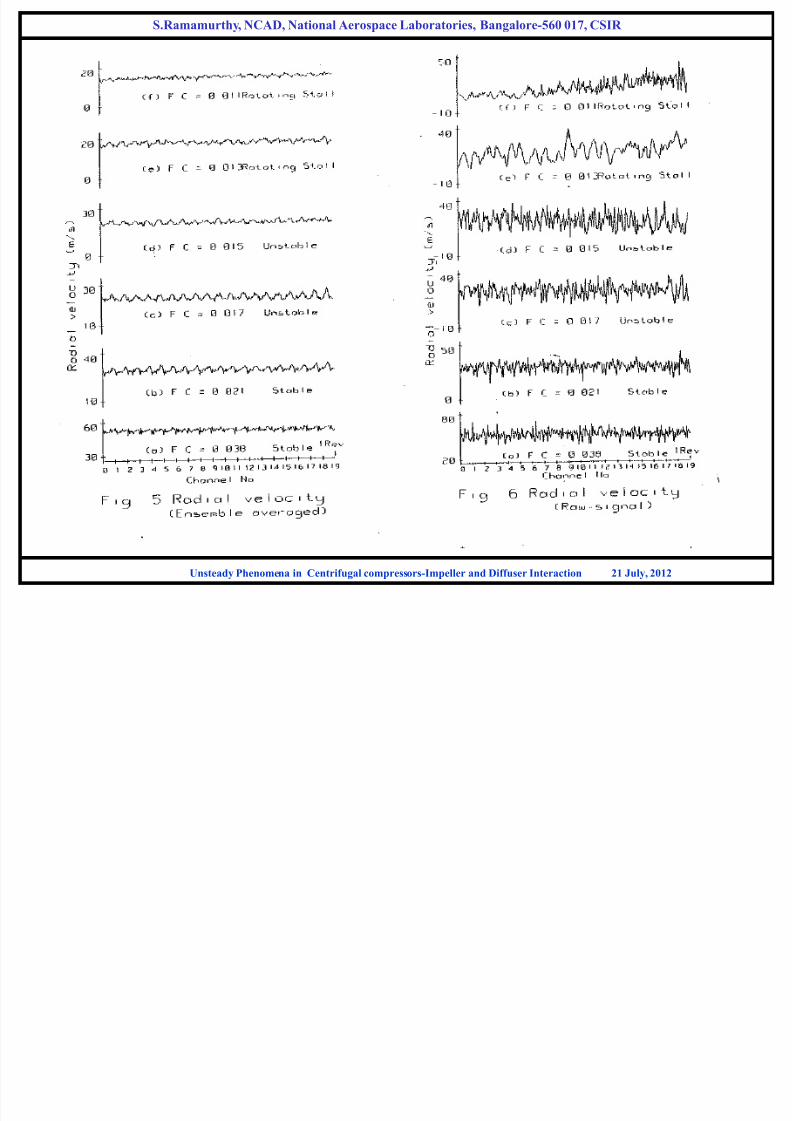
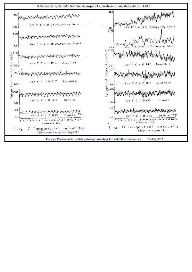
OBSERVATIONS ON STALL INCEPTION
1.The characteristics clearly demarcates regions of stable operation,
instability and rotating stall
2. Instability is identified through bursts of velocity differentials within blade
channel which are not coherence with impeller rotation.
3. Corrective action can be implemented ahead of the stall
Unsteady Phenomena in Centrifugal compressors-Impeller and Diffuser Interaction 21 July, 2012
S.Ramamurthy, NCAD, National Aerospace Laboratories, Bangalore-560 017, CSIR
7/27/2019 Unsteady flow in centrifugal compressor stage
http://slidepdf.com/reader/full/unsteady-flow-in-centrifugal-compressor-stage 57/61
SPECTRAL FLUCTUATIONS
Unsteady Phenomena in Centrifugal compressors-Impeller and Diffuser Interaction 21 July, 2012
S.Ramamurthy, NCAD, National Aerospace Laboratories, Bangalore-560 017, CSIR

7/27/2019 Unsteady flow in centrifugal compressor stage
http://slidepdf.com/reader/full/unsteady-flow-in-centrifugal-compressor-stage 58/61
ENSEMBLE AVERAGED RADIAL AND WHIRL VELOCITY AT IMPELLER OUTLET
TWO CHANNEL VELOCITIES
Unsteady Phenomena in Centrifugal compressors-Impeller and Diffuser Interaction 21 July, 2012
Tangential component
(Whirl component)
Radial component
S.Ramamurthy, NCAD, National Aerospace Laboratories, Bangalore-560 017, CSIR

7/27/2019 Unsteady flow in centrifugal compressor stage
http://slidepdf.com/reader/full/unsteady-flow-in-centrifugal-compressor-stage 59/61
Temporal Variation Spatial Variation
Characteristics of absolute velocity
Unsteady Phenomena in Centrifugal compressors-Impeller and Diffuser Interaction 21 July, 2012
S.Ramamurthy, NCAD, National Aerospace Laboratories, Bangalore-560 017, CSIR
7/27/2019 Unsteady flow in centrifugal compressor stage
http://slidepdf.com/reader/full/unsteady-flow-in-centrifugal-compressor-stage 60/61
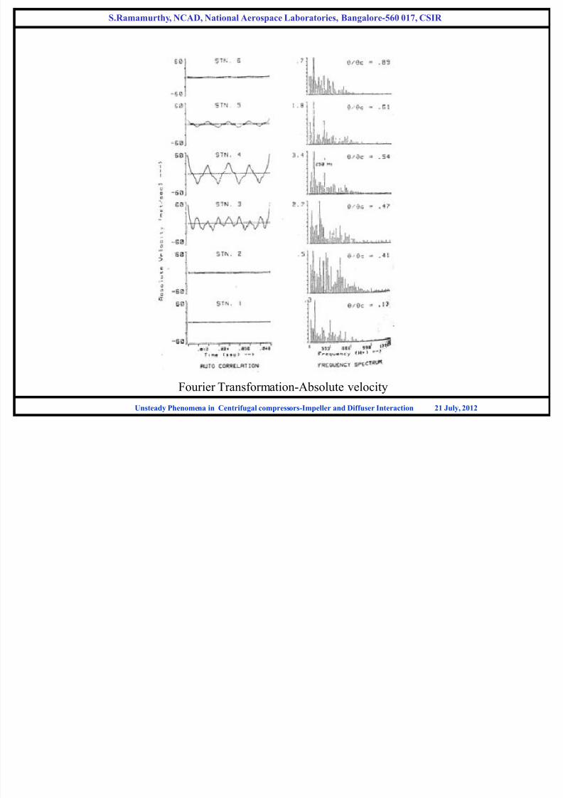
Fourier Transformation-Absolute velocity
Unsteady Phenomena in Centrifugal compressors-Impeller and Diffuser Interaction 21 July, 2012
S.Ramamurthy, NCAD, National Aerospace Laboratories, Bangalore-560 017, CSIR

7/27/2019 Unsteady flow in centrifugal compressor stage
http://slidepdf.com/reader/full/unsteady-flow-in-centrifugal-compressor-stage 61/61
1. The disturbing vortices in the flow had their origin near the suction surface of the
blades well inside the channel and they are found to have travelled half the blade
channel across the flow before exiting and coming out of the impeller.
2. Characterization of vortex shedding is similar to Strouhal Number. Strouhal number for this
particular case works out to be 0.25, which compares well with the universal value of 0.2
3. Unsteady flow observed at impeller outlet is characterized as coherent structure
due to periodic formation of vortex type of disturbances near the blade suction
surfaces and travelling out of the blade passage.4. This vortex formation has not lead to a total separation of flow on the blade suction surface
unlike the consequence of the boundary layer growth.
5. This phenomenon is responsible for the reduced relative velocity as well as
angle and increased work on the flow in the suction side half of the passage
and also for the increasing relative velocity and angle of the flow near the
pressure side, leading to what is known as slip.
6. The periodic formation and cross channel movement of such vertices could
also be the cause of initiation of rotating Stall in impellers.
OBSERVATIONS