Embed Size (px)
Citation preview
2nd Colloque INCA23-24 Octobre 2008
Development of a numerical tool for combustion noiseanalysis in confined domains
C.Silva1, M.Leyko1, E.Gullaud1, F.Nicoud2, T.Poinsot1
1 CERFACS, 42, Av. Gaspard Coriolis, 31057 Toulouse Cedex 1, France
2 University Montpellier II, I3M CNRS UMR 5149, Place Eugène Bataillon, 34095 Montpellier Cedex 5,France
Today, much of the current effort in the field of combustion noise is the development of efficientnumerical tools to calculate the noise radiated by flames. Although unsteady CFD methods asLES or DNS can directly provide the acoustic field radiated by noise sources, this evaluation islimited to small domains due to high computational costs. Hybrid methods have been developedto overcome this limitation. In these schemes, the noise sources are decoupled from the radiatedsound. The sources are still calculated by DNS or LES codes whereas the radiated sound isevaluated by acoustic codes.Firstly the development of AVSP-forced is presented. AVSP-forced is an acoustic code thatdeals with the extension from an existing code dedicated to combustion instability predictions(AVSP-resonant). AVSP-forced is devoted to the analysis of combustion noise in confineddomains. The inhomogeneous Helmholtz equation is solved, in which its wave operator is dis-cretized using a finite volume method with a cell-vertex formulation. Von Neumann, Dirichletand Robin Boundary conditions are taken into account.The right hand side of the Helmholtzequation ,i.e the noise source, is given by an external CFD code. The pressure fluctuation iscalculated by inverting the wave operator matrix using the FGMRES algorithm (Flexible Gen-eralized Minimum Residual method).In the second part of this article one validation test is exposed. It consists in a 2D premixedlaminar flame pulsated by an incoming flow. The combustion noise source, which is function ofthe variation of the unsteady heat release, is calculated from a LES code. The pressure radiationfrom this source is subsequently evaluated using AVSP-forced. A comparison between thepressure fluctuation given directly by the LES code and the one given by the acoustic codeis carried out, showing good agreements. In the last part of this article a two stage premixedswirling combustor developed at Ecole Central de Paris is studied. LES results for the presurefluctuations are compared to those given by AVSP-forced.
INTRODUCTION
In aeronautical industry the design of quiet and ’green’ airplanes has become fundamental. Therefore, envi-ronmental and acoustic pollution are aimed to be reduced in the next generation aeronautical engines. Untiltoday, leaner operating conditions have been achieved in aeronautic gas turbines . However their strong sus-ceptibility to acoustic perturbations has been also observed. In order to evalutate the mechanisms involvedin the interaction between the combustion process and its correspondant acoustics, the understanding ofThermoacoustics theory is essential.Lord Rayleigh(1878) recognized that unsteady flames or, more general, fluctuating heat sources have aneffect on acoustics [1]. At ’right’ circunstances, the heat sources are affected with the sound radiated, andtherefore a feedback loop between combustion and acoustics is created. This is known as Thermoacousticinstability or combustion driven oscillations [2]. When this kind of instability takes place the pressureacoustic amplitude reaches intolerable levels and can induce high structural dammage. Outside the matchingconditions for a thermoacoustic instability to take place, the radiated sound can be seen as a finger print ofthe turbulent flame. Pressure fluctuations produced by the flame are directly dependent of flame dynamics.Flame dynamics, on the contrary, is totally independent of these pressure fluctuations. This open loopsystem, i.e. uncoupled system, is called Direct noise.Noise coming from combustion can also be generated in an indirect manner. It has been seen that hot spots(which may be produced by combustion) travelling at the mean flow velocity, when encountering pressuregradients, as those presented in nozzles, can generate pressure perturbations that are radiated both upstreamand downstream [3]. This source of noise, called Indirect noise can be significative in flows in which the
mean velocity is far for being negligible and the mean pressure is not constant. Summarizing, it is statedthat sound which arises from combustion process in a gas turbine may be categorized in mainly two types:direct combustion noise and indirect combustion noise.The study of combustion noise has been dedicated to express the acoustic phenomena mainly in two dif-ferent stages. The first one is concerned about a good understanding of the generators of sound. Thesegenerators are represented mathematically as source terms in the right hand side of the acoustic equations.These sources are modelled in such a way that they intend to be independent of any acoustic quantity. Thesecond stage is devoted to model the acoustic propagation mechanisms. Its mathematical representation isfound in the left hand side of the respective acoustic equation and can account for refraction effects andinhomogeneities of the flow. This way of representation of acoustics is known as Acoustic Analogies.Lightill acoustic analogy is perhaps one of the most known and referred. The objective of Lighthill’s anal-ogy (1952) is to get a wave equation derived from a rearrengment of the exact Navier Stokes equations. Heshows how the acoustic source terms could be obtained from exact time-acurate calculations or experiments[4]. The wave equation can be solved under integral form if one knows the Green Function that is associatedto the problem in study, which is the case for the open flows [5].Combustion noise investigations are mainly based on inhomogeneous wave equations using an ordinarywave operator. Like Lighthill’s acoustic analogy, those theories are derived by rearranging the conservationequations of mass and momentum and the first and second law of thermodynamics to obtain an inhomoge-neous wave equation [6]. Strahle is the one with probably most publications on this subject. He showedthat the main source of direct noise results from the rate of change of heat release rate associated with thechemical conversion of the reactants. [7]Within the fields of study of combustion noise, computational combustion acoustics (CCA) has received alot of attention in the recent years. CCA is in relativelly naissant state and is concerned to the developmentof computational tools for the estimation of sound radiated by flames [8]. Computational CombustionAcoustics deals with two big issues:
• To correctly model the source of noise which is directly dependent on a right estimation of the flamedynamics properties. Within the different methods for noise source determination, DNS and LESare known as the most novel ones. Direct Numerical Simulation (DNS) solves the Navier StokesEquations comprising all turbulence scales whereas Large Eddy simulation (LES) resolves the NavierStokes Equations for the large scales of turbulence and model the small ones using subgrid closurerules. [9].
• To efficiently predict the far field acoustic radiation due to the noise sources. Acoustic radiationmodelling involves bigger scales than turbulence modelling and calculation domains are also muchbigger. For this reason, acoustic propagation is calculated based on equations devoted for acousticphenomena, and neglects the effects of viscosity. Computational codes resolving the linearized EulerEquations (LEE) are thus highly used. For the simplest cases, when the mean flow is negligible, theeuler equations reduce to the inhomogeneous wave equation. Moreover, under harmonic assumptionsthe wave operator can be transformed to the frequency domain. In this particular case, the waveequation is known as the inhomogeneous Helmholtz equation.
This article presents the first steps in the development of the acoustic code AVSP-forced. This code dealswith the extension from an existing code devoted to combustion instability predictions (AVSP-resonant).AVSP-forced evaluates the acoustic radiation spectrum of confined flames.In the first part of this article, a brief review or the Helmholtz equation is presented followed by a quickdescription of both codes AVSP-resonant and AVSP-forced. A first validation of the code AVSP-forcedis presented in the second part. A two dimensional premixed laminar flame is exposed to inlet velocityfluctuations of the reactants. This causes the heat release of the flame to fluctuate generating in this waypressure waves travelling over the entire domain at the local speed of sound. As a validation exercise, thepressure signal given by LES computations and that one given by AVSP-forced are compared. In the secondpart of this article, a 3D premixed swirled combustor is studied. The acoustic field calculated directly byLES and the one calculated by AVSP-forced are also compared.
2nd Colloque INCA23-24 Octobre 2008
I INSIDE AVSP
I.1 THE WAVE EQUATION FOR REACTING FLOWS
Starting from the governing fluid dynamics equations, one may consider different realistic assumptions inorder to gather the acoustics for low mach number reactive systems in one mathematical expression thatmay be known as the wave equation for low mach number reacting flows [10]. It is therefore stated that:
• The pressure level of the oscillations are small compared to the local mean pressure p′/p << 1
• The system is nearly isobaric so that p ≈ const
• The mean flow is small so that the convective terms in the equation are negligible
As a consequence, the acoustic wave equation for low mach number reacting flows reads
∇ · (c2∇p′)− ∂2p′
∂t2= −(γ − 1)
∂q′
∂t− γp∇v : ∇v +
γp
W
∂2W ′
∂t2(1)
where c, p, γ, q, v, W represent respectivelly the speed of sound, the pressure, heat capacity ratio, the heatrelease rate, the velocity vector and the mixture molar weight. The symbols () and ()′ define respectivellymean quantities and fluctuation quantities.It is worth noting that this equation is slightly different from the one of classical acoustics [11]:
• It is an inhomogeneous equation with three source terms of noise. Starting from the left of the righthand side of the equation one finds the combustion source term, the aerodynamic source term and thenon-isomolar combustion source term.
• The speed of sound is placed inside the divergence operator: This is due to the non-isentropic as-sumption. This ensures to capture acoustic fluctuations with strong variation of the mean temperatureas it occurs close to the flame front.
In the two different cases exposed (see next two sections) in these article, the non-isomolar combustionnoise does not play an importan role in combustion noise generation since the reactant mixtures are highlydilluted in nitrogen. In addition, the aerodynamic source term will be also considered negligible for thelaminar case (2nd section). For the premixed swirled combustor case (3rd section), the aerodynamic sourceof noise may be not negligible, however it is considered small with respect to the noise source associatedwith perturbation of the heat release rate [12].The Inhomogeneous wave equation reduces to
∇ · (c2∇p′)− ∂2p′
∂t2= −(γ − 1)
∂q′
∂t(2)
Under harmonic oscillation assumptions, the pressure fluctuation p′ and the heat fluctuation q′ are expressedas follows [11].
p′(−→x , t) = <(p(−→x )e−iωt) (3)
q′(−→x , t) = <(ˆq(−→x )e−iωt) (4)
where ω = 2πf . The quantities p and ˆq are complex numbers. Replacing now p′ and q′ in the waveequation (equation 2) we obtain the so called Helmholtz equation with a forced term equal to iω(γ − 1)ˆq.This equation should be solved by applying the appropiate Boundary conditions with respect to the pressurep.
∇ · c2∇p+ ω2p = iω(γ − 1)ˆq in Ω+ Boundary Conditions on Γ
(5)
I.2 ABOUT THE HEAT RELEASE RATE
The heat release rate, which is the most important quantity in the combustion source term, can be viewedas the sum of two different terms [13]
q′ = q′noise(ω) + q′amp(p, ω) (6)
• q′amp(p, ω) : The heat release rate is implied in combustion driven oscillations: It is coupled to
pressure fluctuations. This coupling needs to be modeled. It is generally done by the Flame TransferFunction [14]
• q′noise(ω) : The heat release rate is implied in direct combustion noise (also known as combustion
roar). Independent from pressure oscillations.
I.3 DESCRIPTION OF THE ACOUSTIC TOOL AVSP
The acoustic code developped at CERFACS, named AVSP, is a parallel acoustic solver designed to be usedon unstructured meshes. It uses a finite volume (FV) method of order 2 in space.The first usage of AVSP (AVSP-resonant) deals with the prediction of thermoacoustic instabilities andthe capture of the thermoacoustic eigenmodes. This version of the code has been developed for 4 yearsat CERFACS [15].In AVSP-resonant, the flame is considered as an acoustic amplifier (the source termis coupled with the pressure field), so from the mathematical point of view, the problem to solve is aneigenvalue problem which reads
∇ · c2∇p+ ω2p = iω(γ − 1)ˆqamp(p, ω)+ Boundary Conditions
(7)
AVSP-forced version is devoted to the prediction of the acoustic field generated directly by perturbations inthe flame surface area. The flame is considered as an autonomous acoustic source that generates combustionnoise (q′ = q′noise)
∇ · c2∇p+ ω2p = iω(γ − 1)ˆqnoise(ω)+ Boundary Conditions
(8)
A︸︷︷︸∇·c2∇+ω2I
x︸︷︷︸p
= b︸︷︷︸iω(γ−1)ˆqnoise
(9)
For this equation, the mathematical problem to solve is a linear system. This Linear system is resolvedby the Generalized Minimum REsidual (GMRES) method. This algorithm was chosen mainly due to itsportability, simplicity, flexibility and efficiency . GMRES solves large, sparse and non Hermitian linearsystems and belongs to the class of Krylov based iterative methods. This is an important feature that leadsto the no necessity of storing the whole matrix A (less memory computation) but only the product Matrix-vector Ax while the iterative calculation is taking place.AVSP-forcing uses a CERFACS implementation of the GMRES algorithm for both real and complex, singleand double precision arithmetics suitable for serial, shared memory and distributed memory computers [16].
II VALIDATION OF AVSP-FORCED. CASE OF 2D-LAMINAR FLAME
For a preliminary validation of AVSP-forced, a laminar premixed burner has been chosen . This burner,which we will call LeHelley burner [17] , consists of two coaxial tubes of different diameter attached toeach other by one of the extremes. The smaller diameter tube works as the intake whereas the biggerdiameter one works as the chamber. The premixed flammable gas is composed by propane and air mixed atstochiometric equivalent ratio . Figure (1) schematizes Le Helleys burner.The flame produced by this type of burner is ideal to carry out a validation of the acoustic code. AVSP-forced will estimate the acoustic distribution of LeHelley’s burner for given fluctuations in the flame. Thisacoustic distribution depends only on the unsteady heat release source term (see eq. (13)). The aerodynamic

2nd Colloque INCA23-24 Octobre 2008
Figure 1 : LeHelley Burner. Boundary Conditions
source, which depends on strong gradients in the velocity field, is neglected due to the laminarity of the flow.Moreover, the mixture molar weight of the burned gases can be considered equal to that one of the unburnedgases due to their high disolution in nitrogen. This fact permits to consider the non-isomolar combustionsource also as zero.The fluctuation of the heat release rate can be assured if the premixed gases are harmonically perturbed atthe inlet.
II.1 LES CALCULATION
Firstly, an unsteady CFD calculation is needed in order to have the quantities required for the posteriordetermination of the source terms. The numerical tool used is the combustion code AVBP developed atCERFACS. AVBP solves the complete compressible Navier-Stokes equations including chemistry in twoand three space dimensions. The capability to handle structured, unstructured and hybrid grids is an impor-tant key feature of AVBP [18].The intake velocity is equal to 4 m/s which is approximately equivalent to ten times the laminar flame speedfor propane at stochiometric equivalent ratio. Two types of boundary conditions are taken into account fortreating the walls. The first one, which is applied to the intake, imposes a non-slip boundary condition forthe flow. The second type of boundary condition allows the gas to flow tangentially to the chamber walls.Figure (1) shows the boundary conditions applied.The outlet boundary condition, which imposes a mean pressure at the outlet, needs a little more of attention.It is explained as follows
II.1.1 OUTLET BOUNDARY CONDITION
Acoustic analogies consider the sources of noise to be totally independent of the acoustic wave operator.Therefore, in our case, flame dynamics is considered independent to acoustic fluctuations in the chamber.In means to make this assumption valid, it is of extreme importance to reduce the incoming longitudinalacoustic waves (coming from the exit) as much as possible by having no-reflecting boundary conditionsat the outlet. For this case, the chamber walls are not considered important as reflecting bodies sincetransversal acoustic waves (normal to chamber walls) are negligible.Boundary conditions in AVBP are based on method derived by Poinsot and Lele [19] called NSCBC(Navier-Stokes Characteristic Boundary Conditions). In all characteristic approaches, the main issue isthe determination of the amplitudes of waves entering the computational domain. It has been shown thatsubstracting totally the incoming waves (no-reflecting conditions) may induces a drift in the mean flowvalues. However, it is also well known that having strong reflecting boundary conditions can lead to inter-actions between acoustics, hydrodynamics and combustion [20]. A trade off then has to be used. In orderto characterize the reflection of a given boundary, it is useful to introduce the reflection coefficient R. Thereflexion coefficient R is defined as the ratio between the incoming wave amplitude L2 to the outcomingwave amplitude L1. It reads
R = L2/L1 (10)
A totally no reflecting condition would mean R = 0 whereas a totally reflecting condition would readR = 1.
The linear relaxation method (LRM) [19] imposes a proportional relation between the incoming acousticwaves and the difference between the pressure at infinity P∞ and the pressure at the outlet of the computa-tional domain P .
L2 = K(P − P∞) (11)
Here, L2 is the amplitude of the incoming acoustic wave. The coefficient K is known as relaxation coef-ficient. An expression that relates the reflection coefficient R with the relaxation coefficient K has beenestablihed by Selle [21].
R = − 11− i 2ω
K
(12)
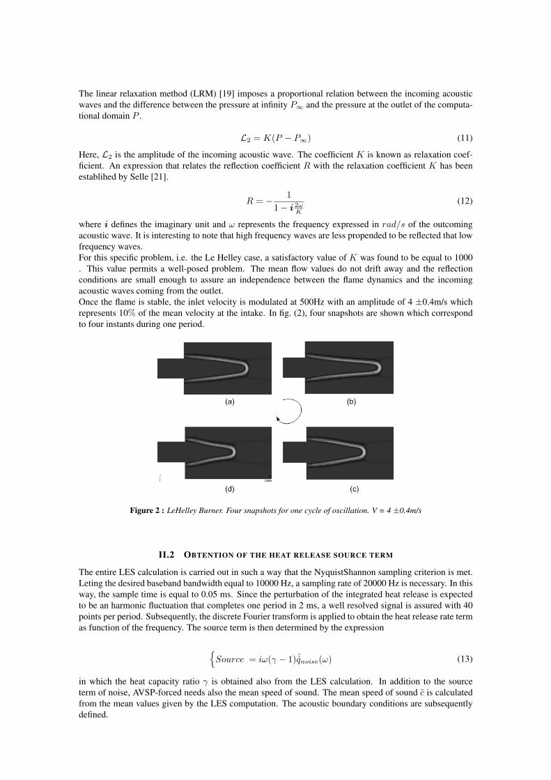
where i defines the imaginary unit and ω represents the frequency expressed in rad/s of the outcomingacoustic wave. It is interesting to note that high frequency waves are less propended to be reflected that lowfrequency waves.For this specific problem, i.e. the Le Helley case, a satisfactory value of K was found to be equal to 1000. This value permits a well-posed problem. The mean flow values do not drift away and the reflectionconditions are small enough to assure an independence between the flame dynamics and the incomingacoustic waves coming from the outlet.Once the flame is stable, the inlet velocity is modulated at 500Hz with an amplitude of 4 ±0.4m/s whichrepresents 10% of the mean velocity at the intake. In fig. (2), four snapshots are shown which correspondto four instants during one period.
Figure 2 : LeHelley Burner. Four snapshots for one cycle of oscillation. V = 4 ±0.4m/s
II.2 OBTENTION OF THE HEAT RELEASE SOURCE TERM
The entire LES calculation is carried out in such a way that the NyquistShannon sampling criterion is met.Leting the desired baseband bandwidth equal to 10000 Hz, a sampling rate of 20000 Hz is necessary. In thisway, the sample time is equal to 0.05 ms. Since the perturbation of the integrated heat release is expectedto be an harmonic fluctuation that completes one period in 2 ms, a well resolved signal is assured with 40points per period. Subsequently, the discrete Fourier transform is applied to obtain the heat release rate termas function of the frequency. The source term is then determined by the expression
Source = iω(γ − 1)ˆqnoise(ω) (13)
in which the heat capacity ratio γ is obtained also from the LES calculation. In addition to the sourceterm of noise, AVSP-forced needs also the mean speed of sound. The mean speed of sound c is calculatedfrom the mean values given by the LES computation. The acoustic boundary conditions are subsequentlydefined.

2nd Colloque INCA23-24 Octobre 2008
II.3 AVSP-FORCED ACOUSTIC BOUNDARY CONDITIONS
Two different types of boundary condtions are taken into account, in order to mimic the acoustic behaviourof LeHelley burner boundaries. Both inlet and walls acoustic response, are modelled assuming an acousticvelocity u′ equal to zero. This boundary condition is representative to totally reflecting walls. The outlet,as stated previously in this article, needs more attention.AVSP-forced relates the acoustic velocity u′ with the acoustic pressure p′ by the notion of impedanceZ = p
ρcu . In view to impose the desired reflection at the duct exit, the reflection coefficient R is related tothe impedance Z as follows
R =Z + 1Z − 1
(14)
The apropiate impedance to be imposed at the outlet is given by combining the eq. (12) and (14)
Z = − 11 + iK/ω
(15)
II.4 AVSP-FORCED RESULTS
The exercise of validation consists in comparing the pressure field given by AVSP-forced and that oneobtained directly after the LES calculation. Three sensors were placed in LeHelley’s chamber as shown infig. (3).The comparison takes place in the spectral domain. As a consequence, the discrete Fourier transformis applied to the temporal pressure signals given by the LES computation so that they can be comparedto AVSP-forced pressure spectrum. Figure (3) shows the sound pressure level (SPL) of both AVBP andAVSP-forced signals.
Figure 3 : LeHelley Burner. Sound Pressure level. Comparison between AVBP and AVSP-forced
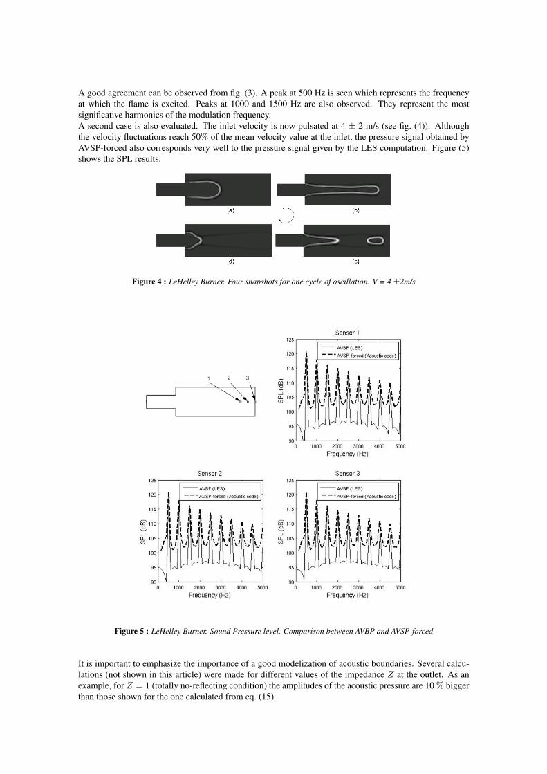
A good agreement can be observed from fig. (3). A peak at 500 Hz is seen which represents the frequencyat which the flame is excited. Peaks at 1000 and 1500 Hz are also observed. They represent the mostsignificative harmonics of the modulation frequency.A second case is also evaluated. The inlet velocity is now pulsated at 4 ± 2 m/s (see fig. (4)). Althoughthe velocity fluctuations reach 50% of the mean velocity value at the inlet, the pressure signal obtained byAVSP-forced also corresponds very well to the pressure signal given by the LES computation. Figure (5)shows the SPL results.
Figure 4 : LeHelley Burner. Four snapshots for one cycle of oscillation. V = 4 ±2m/s
Figure 5 : LeHelley Burner. Sound Pressure level. Comparison between AVBP and AVSP-forced
It is important to emphasize the importance of a good modelization of acoustic boundaries. Several calcu-lations (not shown in this article) were made for different values of the impedance Z at the outlet. As anexample, for Z = 1 (totally no-reflecting condition) the amplitudes of the acoustic pressure are 10 % biggerthan those shown for the one calculated from eq. (15).
2nd Colloque INCA23-24 Octobre 2008
III AVSP-FORCED. VALIDATION FOR A 3D CASE
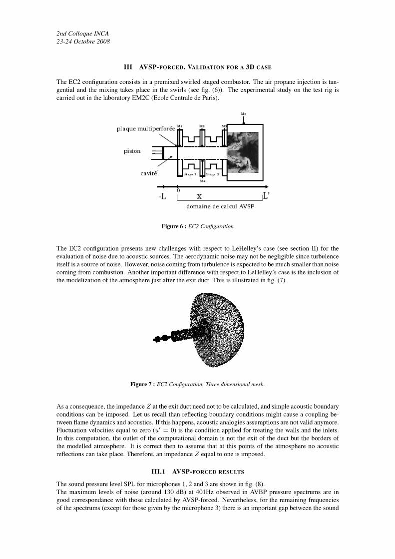
The EC2 configuration consists in a premixed swirled staged combustor. The air propane injection is tan-gential and the mixing takes place in the swirls (see fig. (6)). The experimental study on the test rig iscarried out in the laboratory EM2C (Ecole Centrale de Paris).
Figure 6 : EC2 Configuration
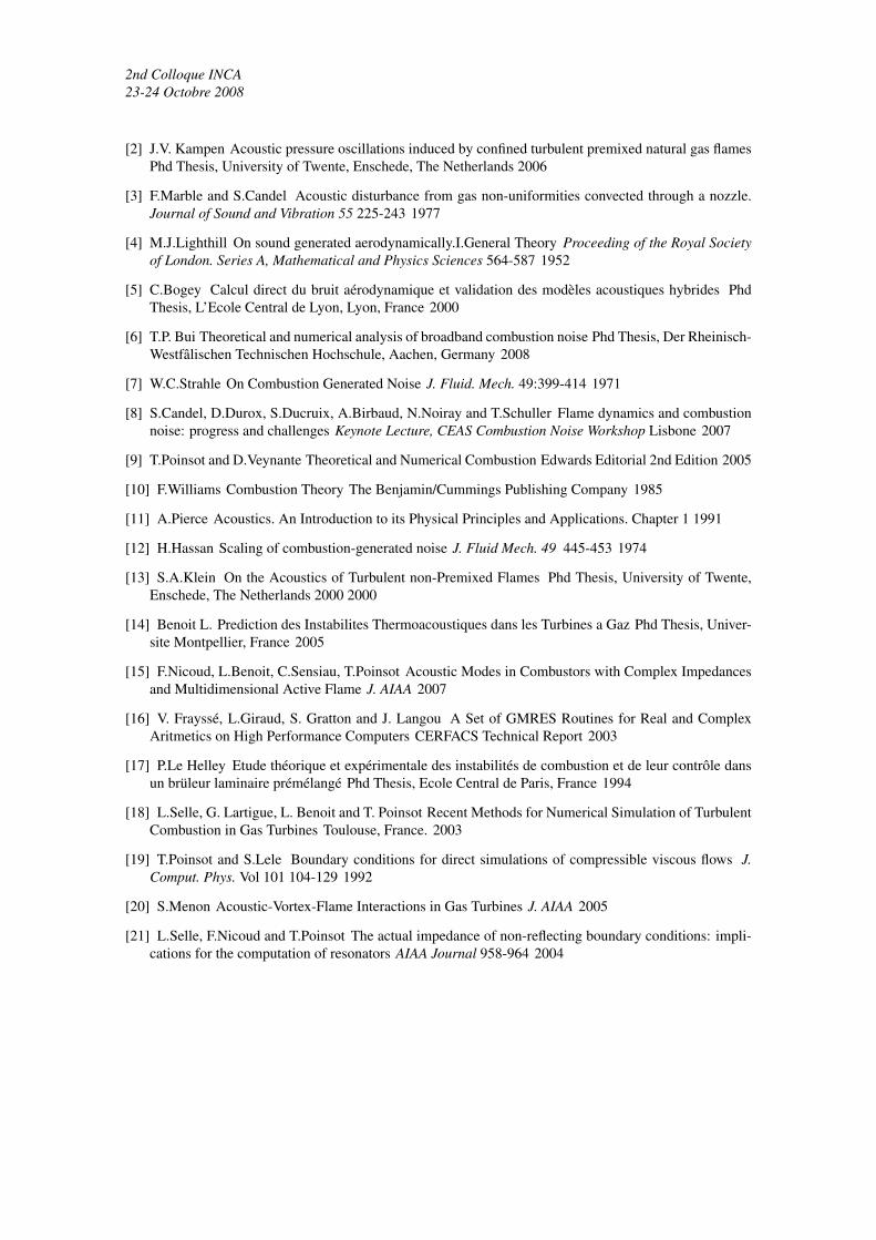
The EC2 configuration presents new challenges with respect to LeHelley’s case (see section II) for theevaluation of noise due to acoustic sources. The aerodynamic noise may not be negligible since turbulenceitself is a source of noise. However, noise coming from turbulence is expected to be much smaller than noisecoming from combustion. Another important difference with respect to LeHelley’s case is the inclusion ofthe modelization of the atmosphere just after the exit duct. This is illustrated in fig. (7).
Figure 7 : EC2 Configuration. Three dimensional mesh.
As a consequence, the impedance Z at the exit duct need not to be calculated, and simple acoustic boundaryconditions can be imposed. Let us recall than reflecting boundary conditions might cause a coupling be-tween flame dynamics and acoustics. If this happens, acoustic analogies assumptions are not valid anymore.Fluctuation velocities equal to zero (u′ = 0) is the condition applied for treating the walls and the inlets.In this computation, the outlet of the computational domain is not the exit of the duct but the borders ofthe modelled atmosphere. It is correct then to assume that at this points of the atmosphere no acousticreflections can take place. Therefore, an impedance Z equal to one is imposed.
III.1 AVSP-FORCED RESULTS
The sound pressure level SPL for microphones 1, 2 and 3 are shown in fig. (8).The maximum levels of noise (around 130 dB) at 401Hz observed in AVBP pressure spectrums are ingood correspondance with those calculated by AVSP-forced. Nevertheless, for the remaining frequenciesof the spectrums (except for those given by the microphone 3) there is an important gap between the sound

Figure 8 : EC2 Configuration. Sound Pressure Level. Comparison between AVBP and AVSP-forced
pressure level calculated by AVSP-forced with respect to AVBP computations. There might be severalreasons for this difference. The most likely is the not-negligible contribution of the aerodynamic noisewhich may be important at the low band frequency.
IV CONCLUSIONS
Two main validations were carried out for testing the reliability of the acoustic code AVSP-forced. Thefirst one consisted in a two dimensional burner in which controlled input oscillations at the inlet wereapplied. The combustion source was evaluated from a compresible LES calculation. This source termis given as an input to the acoustic code AVSP-forced. The pressure signal given by AVSP-forced is ingood correspondance with the LES pos-processed pressure signal. The same procedure was applied to thethree dimensional combustor EC2. Good agreements were reached in certain zones of the SPL spectrum.However in the remaining zones of the spectrum, a gap between both signals (AVBP and AVSP-forced)can be clearly appreciated. Having neglected the aerodynamic noise can be the explanation for this gap.In future calculations this term will be carefully calculated in order to observe its influence as a source ofnoise.
REFERENCES
[1] J.W.S. Rayleigh The Explanation of certain Acoustical Phenomena Nature, XVIII:319-321 1878
2nd Colloque INCA23-24 Octobre 2008
[2] J.V. Kampen Acoustic pressure oscillations induced by confined turbulent premixed natural gas flamesPhd Thesis, University of Twente, Enschede, The Netherlands 2006
[3] F.Marble and S.Candel Acoustic disturbance from gas non-uniformities convected through a nozzle.Journal of Sound and Vibration 55 225-243 1977
[4] M.J.Lighthill On sound generated aerodynamically.I.General Theory Proceeding of the Royal Societyof London. Series A, Mathematical and Physics Sciences 564-587 1952
[5] C.Bogey Calcul direct du bruit aérodynamique et validation des modèles acoustiques hybrides PhdThesis, L’Ecole Central de Lyon, Lyon, France 2000
[6] T.P. Bui Theoretical and numerical analysis of broadband combustion noise Phd Thesis, Der Rheinisch-Westfâlischen Technischen Hochschule, Aachen, Germany 2008
[7] W.C.Strahle On Combustion Generated Noise J. Fluid. Mech. 49:399-414 1971
[8] S.Candel, D.Durox, S.Ducruix, A.Birbaud, N.Noiray and T.Schuller Flame dynamics and combustionnoise: progress and challenges Keynote Lecture, CEAS Combustion Noise Workshop Lisbone 2007
[9] T.Poinsot and D.Veynante Theoretical and Numerical Combustion Edwards Editorial 2nd Edition 2005
[10] F.Williams Combustion Theory The Benjamin/Cummings Publishing Company 1985
[11] A.Pierce Acoustics. An Introduction to its Physical Principles and Applications. Chapter 1 1991
[12] H.Hassan Scaling of combustion-generated noise J. Fluid Mech. 49 445-453 1974
[13] S.A.Klein On the Acoustics of Turbulent non-Premixed Flames Phd Thesis, University of Twente,Enschede, The Netherlands 2000 2000
[14] Benoit L. Prediction des Instabilites Thermoacoustiques dans les Turbines a Gaz Phd Thesis, Univer-site Montpellier, France 2005
[15] F.Nicoud, L.Benoit, C.Sensiau, T.Poinsot Acoustic Modes in Combustors with Complex Impedancesand Multidimensional Active Flame J. AIAA 2007
[16] V. Frayssé, L.Giraud, S. Gratton and J. Langou A Set of GMRES Routines for Real and ComplexAritmetics on High Performance Computers CERFACS Technical Report 2003
[17] P.Le Helley Etude théorique et expérimentale des instabilités de combustion et de leur contrôle dansun brüleur laminaire prémélangé Phd Thesis, Ecole Central de Paris, France 1994
[18] L.Selle, G. Lartigue, L. Benoit and T. Poinsot Recent Methods for Numerical Simulation of TurbulentCombustion in Gas Turbines Toulouse, France. 2003
[19] T.Poinsot and S.Lele Boundary conditions for direct simulations of compressible viscous flows J.Comput. Phys. Vol 101 104-129 1992
[20] S.Menon Acoustic-Vortex-Flame Interactions in Gas Turbines J. AIAA 2005
[21] L.Selle, F.Nicoud and T.Poinsot The actual impedance of non-reflecting boundary conditions: impli-cations for the computation of resonators AIAA Journal 958-964 2004