Embed Size (px)
Citation preview

DEVELOPMENT OF A BETA 0.12, 88 MHZ, QUARTER WAVE RESONATOR AND ITS CRYOMODULE FOR THE SPIRAL2 PROJECT
G. Olry, J-L. Biarrotte, S. Blivet, S. Bousson, C. Commeaux, C. Joly, T. Junquera, J. Lesrel, E. Roy, H. Saugnac, P.Szott, CNRS/IN2P3/IPNO, Orsay, France
Abstract SPIRAL2 is a radioactive beams facility, composed of
a superconducting linac driver, delivering deuterons with an energy up to 40 MeV (5 mA) and heavy ions with an energy of 14.5 MeV/u (1 mA). This facility is now fully approved by the French government.
The first prototype of beta 0.12 quarter-wave resonator has been recently fabricated by Zanon company and tested at IPN Orsay. The details on its fabrication and the results of the RF and mechanical tests at 4K will be presented. Then, we will show the design of the cryomodule-B, dedicated to the high energy section of the linac, which is now ready to be ordered. Finally, the last studies of the R&D program, such as the last optimizations of the geometry, the new developments of the tuning system and the design of the helium vessel, are described.
BETA 0.12 QUARTER WAVE RESONATOR Details on RF and mechanical studies have already
been presented in, respectively [1] and [2]. The goal is to reach an accelerating gradient of 6.5 MV/m with less than 10 W dissipated (NB: Lacc=βλ=0.41 m).
Fabrication The cavity was fabricated by Zanon SpA (Italy) within
6 months (Figure 1). The main problem came from the brazing of the Ø418 mm Stainless Steel ring (needed to fix the Helium vessel) which has required 3 tries.
Figure 1: Beta 0.12 QWR during the fabrication
RRR250 Niobium sheets from TokyoDenkaï were used: 4-mm thick for the cavity walls and 3-mm thick for the stem. The beam tubes and ports aperture is 36 mm.
Figure 2: Beta 0.12 QWR inside the clean room before
the High Pressure Rinsing process.
Cold tests The preparation was done at CEA/Saclay: almost 200
µm were chemically removed (BCP), followed by a 2-hour rinsing process through the bottom and top ports (Figure 2).
A fixed capacitive coupler was used (Ø8 mm antenna) with a 1-kW amplifier (limited to 250 Watts max). The cavity was tested 4 times between January and June (Figure 4) in our Ø800 mm vertical cryostat (Figure 3). Each test required 1500 litres of liquid Helium.
One SC plunger inside the port
Accelerating gap
Stiffening plate in Niobium (4-mm thick)
Figure 3: Beta 0.12 QWR before the test with a SC plunger in one of the top port.
Proceedings of the 12th International Workshop on RF Superconductivity, Cornell University, Ithaca, New York, USA
TUP37 323

Figure 4: Cold tests results: Qo vs. Eacc
Both first experiments (see red and orange curves in Figure 4) were done without testing the static Niobium plungers (see § R&D STUDIES for more details). We reached 11 MV/m (i.e. a voltage gain of 4.4 MV) for a dissipated power of 36 W, without quenching. The Qo value at low field was 1.0 1010, corresponding to a residual resistance of 1.5 nΩ. Then, after 5 days between 70 K and 130 K, we observed the “100 K effect”: i.e. Qo at low field=8.2 108 (⇔ Rresidual = 43 nΩ).
During the last two experiments (see blue and green curves in Figure 4), we have tested two different Niobium plungers. The measured frequency shifts were: +66.9 kHz (test #3) and +18.2 kHz (test #4). 30 % of extra losses were measured using the Ø30 mm plunger: i.e. Qo = 6.8 109 at low field. It was due to the magnetic field on the CF40 Stainless Steel flange (MAFIA simulations gave 20% of extra losses ⇔ Qo=8 109). For the last test, we used a shorter and thinner plunger. No Qo degradation was observed. We reached again 11 MV/m for 25 W dissipated inside the cavity without a quench.
One has to notice that we have faced, during each test, two multipacting barriers: a “strong” one (near 50 kV/m!) which was processed in several hours and a “light” one, near 1.5 MV/m, easily processed within a few minutes.
The static Lorentz detuning factor was measured: KLorentz meas. =-1.58 Hz/(MV/m)². The calculated value, by E. Zaplatin (FZJ), was -1.52 Hz/(MV/m)², assuming an overall cavity thickness of 3.5 mm.
CRYOMODULE
Cryostat The two cavity helium tanks are fed by thermo
siphon from a 20 litres helium buffer vessel installed inside the cryostat.
A thermal shield made of copper, is cooled between 60 K and 80 K with helium gas provided by the refrigerator. The cavity vacuum is separated from the cryostat insulation vacuum to prevent from pollution and allow the use of multilayer insulation inside the cryostat. The static cryogenic losses have been evaluated to be below 10 W at 4 K and below 65 W at 60 K.
Cavities are individually maintained in position by mean of 4 horizontal and 3 vertical titanium alloy rods. In horizontal position, the X shaped antagonist rods keep the cavity position during cool down. The vertical displacement of the cavity is to be compensated by adjusting a misalignment during the assembly at 300 K.
Alignment procedures “Allen & Robson” mires attached to the helium tank
and precisely adjusted to the measured cavity axis materialize the real cavity axis. This axis can be measured through windows placed on the cryostat vacuum vessel. A third axis, materialized by “Allen & Robson” mires, is then used to align all cryomodules with the different elements of the accelerators by mean of a laser tracker.
Proceedings of the 12th International Workshop on RF Superconductivity, Cornell University, Ithaca, New York, USA
324 TUP37
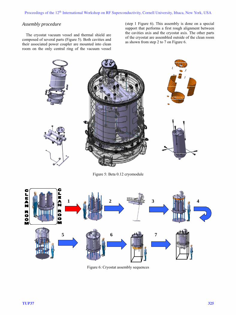
Assembly procedure The cryostat vacuum vessel and thermal shield are
composed of several parts (Figure 5). Both cavities and their associated power coupler are mounted into clean room on the only central ring of the vacuum vessel
(step 1 Figure 6). This assembly is done on a special support that performs a first rough alignment between the cavities axis and the cryostat axis. The other parts of the cryostat are assembled outside of the clean room as shown from step 2 to 7 on Figure 6.
Figure 5: Beta 0.12 cryomodule
1 2 3 4
5 6 7
Figure 6: Cryostat assembly sequences
Proceedings of the 12th International Workshop on RF Superconductivity, Cornell University, Ithaca, New York, USA
TUP37 325

R&D STUDIES
New cavity geometry We are now investigating a new shape of the drift
tubes in order to avoid the “strong” multipacting barrier we observed at very low field level. We think the solution proposed for the modification of the half-wave resonator built by ACCEL could be a good solution [3]. We also look for rounded shape instead of titled walls.
Cavity tuning systems A first warm tuning of the cavity was performed
during the manufacturing of the first prototype. An adjustment of the gap distance within a range of +/- 2 mm around the theoretical distance was done before the 3 last welds. An accuracy of 80 kHz was achieved and should be improved for the next cavities.
Tuning by deforming the cavity walls is only possible by applying loads on the cylindrical body but gives a low sensitivity of around 4 kHz/mm and a tuning range of 8 kHz. A conceptual design of such a tuner is presented Figure 7.
Figure 7: Cavity tuning system by deformation.
Due to the small tuning range of this solution, an alternative way to tune the cavity is investigated. It consists in introducing Niobium plungers cooled @ 4 K in the magnetic volume of the cavity. A first test on a rough prototype fixed on one of the upper cavity port shows encouraging results (see green curve in Figure 4) without any measurable effects on the RF cavity performances and a tuning shift of around + 18 kHz. A movable plunger is under study and is planned to be tested at the beginning of 2006. It is expected to obtain a sufficient dynamical adjustment of the frequency of +/- 4 kHz around the nominal frequency, the cavity bandwidth being around 80 Hz at 4 K.
The warm tuning will be performed by mixing the adjustment of the gap distance during manufacturing and the use of fixed plungers. For the dynamic cold
tuning, tests are planed in 2006 to validate the best technical solution.
Figure 8: SC plungers models.
Helium vessel design The first prototype will have a Stainless Steel
Helium vessel (currently under fabrication at Zanon SpA, delivery foreseen in October). We are now designing a new vessel in Titanium (Figure 9) in order to avoid the brazing of the big Stainless Steel ring which has caused some problems and, more important, to fix the top of the stem on the vessel to compensate its vertical displacement and increase the frequency of the first mechanical vibration modes.
Connexion between the stem and the Helium vessel using a Titanium ring
Helium vessel welded on the cavity body
Figure 9: New design of the Helium vessel.
CONCLUSION Following the good results obtained with the first
prototype, we are going to launch the fabrication of two new cavities, equipped with their Titanium Helium tank and their dynamic cold tuning system. In parallel, the fabrication of the cryomodule is planned in 2006. The assembly will take place at IPN. The first test of the fully equipped cryomodule with two cavities and
Proceedings of the 12th International Workshop on RF Superconductivity, Cornell University, Ithaca, New York, USA
326 TUP37

their power couplers is foreseen at the beginning of 2007.
ACKNOWLEDGEMENTS The authors thank E. Zaplatin for his precious and
precise calculations. We thank also the team of CEA/Saclay for their help during the preparation of the cavity.
REFERENCES [1] T. Junquera et al., “High intensity linac driver for
the SPIRAL 2 project”, EPAC 2004, Lucerne, Switzerland, June 2004.
[2] H. Saugnac et al., “Mechanical stability simulations on a quarter wave resonator for the SPIRAL2 project”, LINAC2004, Lübeck, Germany, August 2004.
[3] M. Pekeler et al., “Performance of a prototype 176 MHz, beta 0.09, half-wave resonator for the SARAF linac”, these proceedings.
Proceedings of the 12th International Workshop on RF Superconductivity, Cornell University, Ithaca, New York, USA
TUP37 327