Embed Size (px)
Citation preview
Development and Assessment of Regeneration
Methods for Commercial Automotive Three-Way Catalysts
Henrik Birgersson
Doctoral Thesis 2006
KTH – Royal Institute of Technology Department of Chemical Engineering and Technology
Chemical Technology SE-100 44 Stockholm, Sweden

TRITA-KET R227 ISSN 1104-3466 ISRN KTH/KET/R--227--SE ISBN 91-7178-343-1


v
Abstract Car exhaust catalysts were introduced in the early 1980’s, to limit the release of pollutants such as hydrocarbons, carbon monoxide and nitrogen oxides. These catalysts contain noble metals such as palladium (Pd), platinum (Pt) and rhodium (Rh) and are able to simultaneously abate all three of the above-mentioned pollutants, hence the name three-way catalyst (TWC). The exposure to high temperatures (800-1000 °C) during operation and the presence of additives in gasoline and lubricants will, after a certain time, lower the activity of the TWC. High temperatures reduce the active area by causing the noble metals to agglomerate and sinter, whereas the additives alter the activity either by fouling the pores of the support material or by interacting with the metals. The main objective of this work was to develop a method which allows for the removal of contaminants (additives) from the washcoat and enables the redispersion of the active sites (noble metals), in an effort to recover lost catalyst activity. For this purpose, regeneration experiments were carried out on a wide spectrum of different commercial car exhaust catalysts. The influence of a thermal treatment in a controlled gas atmosphere, such as oxygen or hydrogen, and a redispersing agent, e.g. chlorine, on the activity of TWC was investigated by means of laboratory-scale activity measurements. Several complementary characterization methods such as SEM/TEM, XRD, BET, LA, XPS and TPR were employed to verify the effects of the regeneration treatments on the catalyst morphology (Papers I, II). The results show that partial regeneration of catalyst activity and noble metal dispersion was achieved after thermal treatment in an oxygen-chlorine rich atmosphere at temperatures below 500 °C. A wet-chemical regeneration treatment with dilute oxalic and citric acid solutions is evaluated in Paper III. These acidic solutions are able to dissolve and remove contaminants from the washcoat, thus partly restoring the catalyst activity. An investigation of the effects of an oxy-chlorine thermal treatment for regeneration of a ‘full-scale’ commercial automotive three-way catalyst was carried out (Paper IV). Improved catalyst activity for a high mileage catalyst could be observed, with emissions lowered by approximately 30 to 40 vol.% over the EC2000 driving cycle. The properties of fresh, aged and regenerated catalysts were then studied by means of lab-scale experiments, on a local as well as a global level using a mathematical model (Paper V). The model allows for comparison of the intrinsic properties of the active surface by deriving and tuning parameters of a fresh catalyst and verifying the activity of a regenerated or aged catalyst. Keywords: automotive catalyst, TWC, aging, sintering, Pd/Rh, Pt/Rh, regeneration, oxy-chlorination, dispersion, acid-leaching, mathematical modeling, reaction kinetics
vi
Sammanfattning Bilavgaskatalysatorn introducerades i början av 1980-talet för att minska utsläppen av föroreningar som kolväten, koloxid och kväveoxider. Dessa katalysatorer innehåller ädelmetaller såsom palladium (Pd), platina (Pt) och rodium (Rh) och de kan samtidigt minska mängden av alla de tre nämnda föroreningarna, därav namnet trevägskatalysator. Katalysatorn utsätts för höga temperaturer (800-1000 °C) under drift. Detta tillsammans med förekomsten av tillsatser i bensin och motoroljor försämrar med tiden katalysatorns effektivitet. Höga temperaturer minskar den aktiva ytan genom att ädelmetaller ansamlas och sintrar medan tillsatserna ändrar aktiviteten antingen genom att sätta igen porerna i bäraren eller genom att interagera med metallerna. Det huvudsakliga målet med detta arbeta har varit att utveckla en metod för att avlägsna föroreningar (tillsatser) samt möjliggöra en redispergering av de katalytiskt aktiva sätena (ädelmetaller), i ett försök att återfå förlorad katalytisk aktivitet. För detta ändamål utvärderades olika regenererings-metoder på ett brett spektrum av olika kommersiella bilavgaskatalysatorer. Inflytandet av värmebehandling i en kontrollerad gasatmosfär, bestående av syre eller väte med tillsats av ett redispergerande ämne, t.ex. klor, på trevägskatalysatorns aktivitet undersöktes medelst försök i laboratorieskala. Ett antal kompletterande karakteriseringsmetoder som SEM/TEM, XRD, BET, LA, XPS och TPR användes för att utröna effekten av den regenerande behandlingen på katalysatorns morfologi (artikel I, II). En partiell regenerering av både katalysatorns aktivitet och ädelmetallernas dispersion kunde iakttas efter värmebehandling i en miljö rik på syre och klor vid temperaturer under 500 °C. En våtkemisk behandling medelst utspädda oxal- och citronsyralösningar utvärderas i artikel III. Dessa syralösningar kan lösa upp och ta bort föroreningar från katalysatorn och därmed delvis återställa den katalytiska aktiviteten. En undersökning av effekterna av en termisk behandling i en miljö rik på syre och klor på en ’full-skale’ kommersiell katalysator utfördes (artikel IV). Förbättrad katalytisk aktivitet för en katalysator med högt miltal kunde iakttas, med en sänkning av utsläppen med uppskattningsvis 30 till 40 vol.% över hela EC2000 körcykeln. Egenskaperna hos nya, åldrade och regenererade katalysatorer studerades med både en matematisk modell och försök i labskala (artikel V). Modellen möjliggör jämförandet av inneboende egenskaper hos den aktiva ytan. Efter härledning finjusterades modellen för den nya katalysatorn och den åldrade och regenerade katalysatorns effektivitet med avseende på att reducera föroreningar kunde undersökas och verifieras. Nyckelord: bilavgaskatalysator, TWC, åldring, sintring, Pd/Rh,Pt/Rh, regenerering, syre-klor, dispersion, syralakning, matematisk modellering, reaktionskinetik
vii
List of papers This thesis is based on the following publications, referred to by their Roman numerals. The papers are appended at the end of the thesis. I. Thermal gas treatment to regenerate spent automotive three-way exhaust gas catalysts
(TWC) H. Birgersson, M. Boutonnet, S. Järås, L. Eriksson, Appl. Catal. B 54 (2004) 193.
II. An investigation of a new regeneration method of commercial aged three-way catalysts H. Birgersson, M. Boutonnet, F. Klingstedt, D. Yu Murzin, P. Stefanov, A. Naydenov, Appl. Catal. B 65 (2006) 93.
III. Reactivation of an Aged Commercial Three-Way Catalyst by Oxalic and Citric Acid Washing S.Y. Christou, H. Birgersson, J.L.G. Fierro, A.M. Efstathiou, Environ. Sci. Tech. 40 (2006) 2030.
IV. Regeneration of spent commercial automotive three-way exhaust gas catalysts (TWC)
H. Birgersson, L. Eriksson, M. Boutonnet, S. Järås, Manuscript. V. Mathematical Analysis of Thermally Oxy-Chlorine Regenerated Three-Way Catalysts
H. Birgersson, E. Birgersson, M. Boutonnet, Submitted to Chem. Eng. Sci. Other Publications Other publications on catalysis not included in this thesis. 1. Deactivation and regeneration of spent three-way automotive exhaust gas catalysts
(TWC) H. Birgersson, M. Boutonnet, S. Järås, L. Eriksson, Top. Catal. 30 (2004) 433.
2. Production of hydrogen from methanol over Cu/ZnO catalysts promoted by ZrO2 and Al2O3 J. Agrell, H. Birgersson, M. Boutonnet, I. Melián-Cabrera, R.M. Navarro, J.L.G. Fierro, J. Catal., 219 (2003) 389.
3. Steam reforming of methanol over a Cu/ZnO/Al2O3 catalyst: A kinetic analysis and strategies for suppression of CO formation J. Agrell, H. Birgersson, M. Boutonnet, J. Power Sources, 106 (2002) 247.
viii
Contributions to the publications
I. H. Birgersson (HB) is the main author of this paper and performed the experiments with some feedback from L. Eriksson (LE). K. Jansson carried out the TEM analysis with feedback from HB.
II. HB is the principal author of this paper and performed the main part of the
experiments, except the XPS analysis, which was provided by P. Stefanov and A. Naydenov. The H2 chemisorption and BET analysis were carried out in close cooperation between HB and F. Klingstedt. C. Ekholm performed the SEM-EDX analysis, whilst P. Ek performed the Laser Ablation analysis with feedback from HB.
III. The report was written mainly by A.F. Efstathiou with feedback from
S.Y. Christou and HB. HB performed the activity tests and the evaluation thereof.
IV. HB is the main author of this report and performed the experiments, except for the full-scale activity measurements, which were carried out in close cooperation between HB and LE.
V. The problem formulation for the mathematical model, coding, numerical
simulations and post-processing were performed in close cooperation between HB and E. Birgersson (EB). HB carried out the experiments. HB wrote the report with feedback from EB.
ix
Table of contents 1 Introduction ......................................................................................................................... 1
1.1 Scope of the thesis........................................................................................................ 3
2 Automotive three-way catalysts (TWC) ............................................................................. 5
3 Aging phenomena of the automotive three-way catalyst .................................................. 11
3.1 Chemical deactivation ................................................................................................ 12
3.2 Thermal deactivation.................................................................................................. 14
4 Experimental set-up........................................................................................................... 19
4.1 Catalysts ..................................................................................................................... 19
4.2 KTH equipment set-up (Regeneration) ...................................................................... 19
4.3 AVL-MTC small-scale experiment set-up (Activity tests) ........................................ 20
5 Characterization of three-way catalysts ............................................................................ 23
5.1 Scanning Electron Microscopy (SEM) and Energy Dispersive X-ray Spectroscopy
(EDX) ............................................................................................................................... 24
5.2 Transmission electron microscopy (TEM)................................................................. 24
5.3 Temperature programmed reduction (TPR)............................................................... 25
5.4 Chemisorption analysis .............................................................................................. 26
5.5 Brunauer, Emmet and Teller analysis (BET) ............................................................. 26
5.6 X-Ray Diffraction (XRD) .......................................................................................... 26
5.7 X-Ray Photoelectron Spectroscopy (XPS) ................................................................ 27
5.8 Laser Ablation (LA) ................................................................................................... 28
6 Investigation of regeneration procedures for TWC........................................................... 29
6.1. Thermal gas treatments (Papers I, II) ........................................................................ 29
6.2. Wet-chemical treatments (Paper III) ......................................................................... 35
7 Regeneration of full scale TWC........................................................................................ 37
7.1 Full-scale activity tests ............................................................................................... 37
7.2 Results from full-scale activity tests (Paper IV) ........................................................ 38
x
8 Mathematical analysis of oxy-chlorine regenerated TWC................................................ 41
8.1 Model description (Paper V) ...................................................................................... 41
8.2 Governing equations .................................................................................................. 43
9 Conclusions ....................................................................................................................... 47
References ............................................................................................................................ 53
Paper I: Thermal gas treatment to regenerate spent automotive three-way exhaust gas
catalysts (TWC) Paper II: An investigation of a new regeneration method of commercial aged three-way
catalysts Paper III: Reactivation of an Aged Commercial Three-Way Catalyst by Oxalic and Citric
Acid Washing Paper IV: Regeneration of spent commercial automotive three-way exhaust gas catalysts
(TWC) Paper V: Mathematical Analysis of Thermally Oxy-Chlorine Regenerated Three-Way
Catalysts
1
1 Introduction Since the beginning of the twentieth century there has been a steady increase in the production of motor vehicles, amounting to 55 million per year worldwide at the present time. North America was the largest producer of vehicles during the 1950’s, to be surpassed by a steadily increasing market in Europe at the end of the 1960’s. To date, new and ever-growing transportation sectors in Asia and Latin America are estimated to lead to an increase in the world vehicle fleet by over 100 % by 2030. With approximately 800 million vehicles currently in service worldwide, the impact of such a growth on already heavily strained road networks and the environment is and will be substantial [1]. Emissions of hazardous gases stemming from the vehicle propulsion system, such as spark-ignition or diesel engines, are already major culprits even in rural areas. Such gases, mainly composed of carbon monoxide (CO), unburnt or partially burnt hydrocarbons (HC), oxides of nitrogen (NOx) and particulates (PM), cause smog, acid rain and various human health problems [3,4], to name but a few consequences. In the following, a brief overview of the three major pollutants will be given, not including particulate matter mainly stemming from diesel or lean-burn engines. Carbon monoxide (CO) is formed primarily due to incomplete or partial combustion of hydrocarbons in the engine, mainly under oxygen-deficient conditions (fuel-rich). However, inadequate fuel vaporization or mixing and the existence of oxygen-poor regions in the engine cylinders lead to the formation of CO even under fuel-lean combustion [4]. For humans, CO has a greater affinity to bonding with hemoglobin in blood than oxygen, thereby reducing the supply of oxygen to the body. A few hundred ppm causes dizziness and headache whereas several thousand ppm CO is lethal. It is thus highly toxic to humans, especially so in enclosed spaces and high-density traffic areas.
2
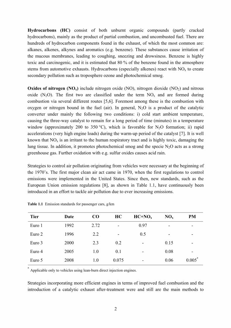
Hydrocarbons (HC) consist of both unburnt organic compounds (partly cracked hydrocarbons), mainly as the product of partial combustion, and uncombusted fuel. There are hundreds of hydrocarbon components found in the exhaust, of which the most common are: alkanes, alkenes, alkynes and aromatics (e.g. benzene). These substances cause irritation of the mucous membranes, leading to coughing, sneezing and drowsiness. Benzene is highly toxic and carcinogenic, and it is estimated that 80 % of the benzene found in the atmosphere stems from automotive exhausts. Hydrocarbons (especially alkenes) react with NOx to create secondary pollution such as troposphere ozone and photochemical smog. Oxides of nitrogen (NOx) include nitrogen oxide (NO), nitrogen dioxide (NO2) and nitrous oxide (N2O). The first two are classified under the term NOx and are formed during combustion via several different routes [5,6]. Foremost among these is the combustion with oxygen or nitrogen bound in the fuel (air). In general, N2O is a product of the catalytic converter under mainly the following two conditions: i) cold start ambient temperature, causing the three-way catalyst to remain for a long period of time (minutes) in a temperature window (approximately 200 to 350 °C), which is favorable for N2O formation; ii) rapid accelerations (very high engine loads) during the warm-up period of the catalyst [7]. It is well known that NOx is an irritant to the human respiratory tract and is highly toxic, damaging the lung tissue. In addition, it promotes photochemical smog and the specie N2O acts as a strong greenhouse gas. Further oxidation with e.g. sulfur oxides causes acid rain. Strategies to control air pollution originating from vehicles were necessary at the beginning of the 1970’s. The first major clean air act came in 1970, when the first regulations to control emissions were implemented in the United States. Since then, new standards, such as the European Union emission regulations [8], as shown in Table 1.1, have continuously been introduced in an effort to tackle air pollution due to ever increasing emissions. Table 1.1 Emission standards for passenger cars, g/km
Tier Date CO HC HC+NOx NOx PM
Euro 1 1992 2.72 - 0.97 - -
Euro 2 1996 2.2 - 0.5 - -
Euro 3 2000 2.3 0.2 - 0.15 -
Euro 4 2005 1.0 0.1 - 0.08 -
Euro 5 2008 1.0 0.075 - 0.06 0.005*
* Applicable only to vehicles using lean-burn direct injection engines. Strategies incorporating more efficient engines in terms of improved fuel combustion and the introduction of a catalytic exhaust after-treatment were and still are the main methods to
3
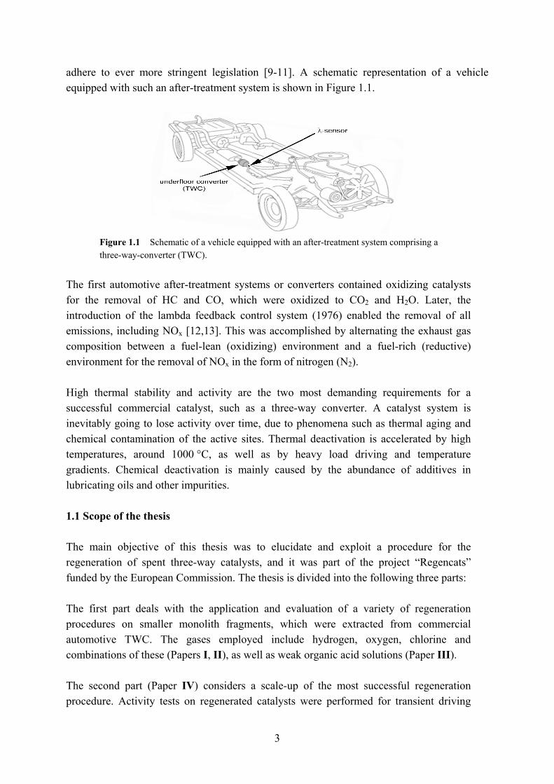
adhere to ever more stringent legislation [9-11]. A schematic representation of a vehicle equipped with such an after-treatment system is shown in Figure 1.1.
Figure 1.1 Schematic of a vehicle equipped with an after-treatment system comprising a three-way-converter (TWC).
The first automotive after-treatment systems or converters contained oxidizing catalysts for the removal of HC and CO, which were oxidized to CO2 and H2O. Later, the introduction of the lambda feedback control system (1976) enabled the removal of all emissions, including NOx [12,13]. This was accomplished by alternating the exhaust gas composition between a fuel-lean (oxidizing) environment and a fuel-rich (reductive) environment for the removal of NOx in the form of nitrogen (N2). High thermal stability and activity are the two most demanding requirements for a successful commercial catalyst, such as a three-way converter. A catalyst system is inevitably going to lose activity over time, due to phenomena such as thermal aging and chemical contamination of the active sites. Thermal deactivation is accelerated by high temperatures, around 1000 °C, as well as by heavy load driving and temperature gradients. Chemical deactivation is mainly caused by the abundance of additives in lubricating oils and other impurities. 1.1 Scope of the thesis The main objective of this thesis was to elucidate and exploit a procedure for the regeneration of spent three-way catalysts, and it was part of the project “Regencats” funded by the European Commission. The thesis is divided into the following three parts: The first part deals with the application and evaluation of a variety of regeneration procedures on smaller monolith fragments, which were extracted from commercial automotive TWC. The gases employed include hydrogen, oxygen, chlorine and combinations of these (Papers I, II), as well as weak organic acid solutions (Paper III). The second part (Paper IV) considers a scale-up of the most successful regeneration procedure. Activity tests on regenerated catalysts were performed for transient driving

4
conditions; rapid variations in both exhaust gas composition, temperature, and flow-rate. Experiments were performed on a Volvo 245 test vehicle, utilizing a low and a high mileage catalyst, respectively. The third part (Paper V) concludes with a kinetic model, which aims to capture the light-off characteristics of fresh, aged and regenerated catalysts. The model furthermore allows for comparison of the intrinsic properties of the active surface by deriving and tuning parameters of a fresh catalyst and verifying the activity of a lab-scale regenerated or aged catalyst.
5
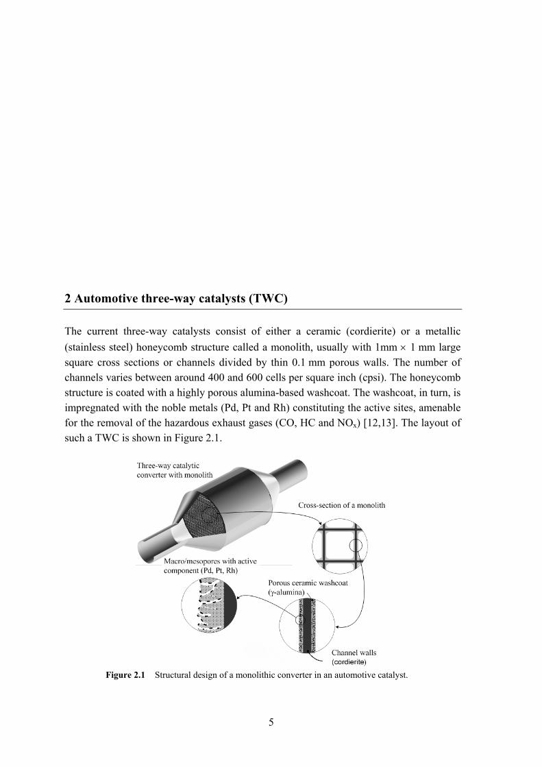
2 Automotive three-way catalysts (TWC) The current three-way catalysts consist of either a ceramic (cordierite) or a metallic (stainless steel) honeycomb structure called a monolith, usually with 1mm × 1 mm large square cross sections or channels divided by thin 0.1 mm porous walls. The number of channels varies between around 400 and 600 cells per square inch (cpsi). The honeycomb structure is coated with a highly porous alumina-based washcoat. The washcoat, in turn, is impregnated with the noble metals (Pd, Pt and Rh) constituting the active sites, amenable for the removal of the hazardous exhaust gases (CO, HC and NOx) [12,13]. The layout of such a TWC is shown in Figure 2.1.
Figure 2.1 Structural design of a monolithic converter in an automotive catalyst.
6
It is vital for the performance of the exhaust converter that the washcoat exhibits a large surface-to-volume ratio, as well as remains stable even at high temperature (1000 °C). For these purposes, a high surface-area γ-alumina (100-200 m2/g) is often employed, which is capable of maintaining a stable structure even at high temperatures. To enhance the thermal stability of γ-Al2O3, it is often loaded with several base-metal oxides, such as ZrO2, La2O3 and/or BaO [14,15]. Further, by adding CeO2, oxygen donor sites and oxygen storage components are obtained [16-22]. Typically, the washcoat constitutes about 20 wt.% of the final monolith. A more detailed overview of the most common base and precious metals and their respective properties in the three-way catalyst follows. Cerium (Ce), first introduced in the mid-1980s [23], nowadays constitutes a large proportion of the washcoat (in the order of 30 wt.%). The high fraction is explained by its ability to undergo periodic oxidation and reduction, depending on the exhaust gas redox environment. It is further able to store excess oxygen to buffer lean perturbations and release said oxygen to enhance conversion when fuel-rich conditions prevail [24]. This ability stems from the lattice ion mobility and the relative ease with which it can switch between Ce(III) and Ce(IV) redox states [25] according to equations (2.1) and (2.2). Oxygen storage ability of CeO2: Fuel-rich conditions (λ<1): 2 2 3 22 IV IIICe O CO Ce O CO+ → + (2.1)
Fuel-lean conditions (λ>1): 2 3 2 21 22
III IVCe O O Ce O+ → (2.2)
In addition, it has been found that cerium further improves the three-way catalyst performance in the removal of NOx, CO and HC, due to the formation of catalytically active sites at the precious metal and CeO2 interface [26-28]. Ce hereby stabilizes the precious metals and thereby upholds a high dispersion. Finally, cerium promotes the water-gas shift reaction, which is a path to remove CO under transient rich operation [12,29] according to equation (2.3) below. The water gas-shift reaction:
2 2 2CO H O CO H+ → + (2.3)
Zirconia (Zr) is added to the washcoat to stabilize both the Ce oxide and the washcoat (Al2O3) metals. Furthermore Zr greatly improves the OSC of Ce, upholding these properties even after thermal aging at high temperatures [30,31].
7
Apart from stabilizing the γ-alumina [32-35], barium (Ba) functions as an NOx storage material, maintaining low NOx emissions under fuel-lean conditions (λ>1). Here, NOx is stored as a surface nitrate on the BaO sites according to equations (2.4) and (2.5).
2 2Pt PdNO O NO+ ⎯⎯⎯→ (2.4)
( ) ( )222 2 2 3 2
- NONONO BaO BaO NO BaO Ba NO++ → ⎯⎯⎯→ ⎯⎯⎯→ (2.5)
Once the engine runs under fuel-rich conditions (λ<1) again, the NOx is released and catalytically reduced to N2 according to equation (2.6) [13,36-38].
( ) ( ) 22 3 2 22
. ./ reduced by e g HBaO NO Ba NO BaO N H O⎯⎯⎯⎯⎯⎯→ + + (2.6)
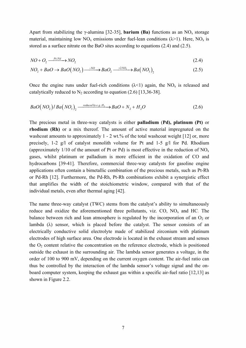
The precious metal in three-way catalysts is either palladium (Pd), platinum (Pt) or rhodium (Rh) or a mix thereof. The amount of active material impregnated on the washcoat amounts to approximately 1 - 2 wt.% of the total washcoat weight [12] or, more precisely, 1-2 g/l of catalyst monolith volume for Pt and 1-5 g/l for Pd. Rhodium (approximately 1/10 of the amount of Pt or Pd) is most effective in the reduction of NOx gases, whilst platinum or palladium is more efficient in the oxidation of CO and hydrocarbons [39-41]. Therefore, commercial three-way catalysts for gasoline engine applications often contain a bimetallic combination of the precious metals, such as Pt-Rh or Pd-Rh [12]. Furthermore, the Pd-Rh, Pt-Rh combinations exhibit a synergistic effect that amplifies the width of the stoichiometric window, compared with that of the individual metals, even after thermal aging [42]. The name three-way catalyst (TWC) stems from the catalyst’s ability to simultaneously reduce and oxidize the aforementioned three pollutants, viz. CO, NOx and HC. The balance between rich and lean atmosphere is regulated by the incorporation of an O2 or lambda (λ) sensor, which is placed before the catalyst. The sensor consists of an electrically conductive solid electrolyte made of stabilized zirconium with platinum electrodes of high surface area. One electrode is located in the exhaust stream and senses the O2 content relative the concentration on the reference electrode, which is positioned outside the exhaust in the surrounding air. The lambda sensor generates a voltage, in the order of 100 to 900 mV, depending on the current oxygen content. The air-fuel ratio can thus be controlled by the interaction of the lambda sensor’s voltage signal and the on-board computer system, keeping the exhaust gas within a specific air-fuel ratio [12,13] as shown in Figure 2.2.
8
Figure 2.2 Conversion efficiency of NO, CO and HC as a function of the air-fuel ratio in a three-way catalytic converter.
The possible reaction mechanisms occurring on the catalyst are as follows [12,13]: Oxidation reactions (Pt/Pd) under fuel-lean conditions:
2 212
CO O CO+ → (2.7)
2 2 212
H O H O+ → (2.8)
2 2 24 2x yy yC H x O xCO H O⎛ ⎞+ + → +⎜ ⎟
⎝ ⎠ (2.9)
NOx reduction (Rh) under fuel-rich conditions:
2 22 2 2CO NO CO N+ → + (2.10)
2 2 222 2 4x yy y yC H x NO xCO H O x N⎛ ⎞ ⎛ ⎞+ + → + + +⎜ ⎟ ⎜ ⎟
⎝ ⎠ ⎝ ⎠ (2.11)
2 2 212
H NO H O N+ → + (2.12)
Under steady, warmed-up conditions the TWC performs adequately. However, there are three circumstances which may cause undesirably high levels of emissions:
• During the warm-up period of the three-way catalyst (within the first 200 seconds) about 60-80 % of the total HC emissions are produced [12]. The catalyst acts as a heat exchanger during the cold start, with the catalyst being heated by the warm exhaust gas. The heat transfer between exhaust gas and the catalyst is correlated to the geometric surface area, cell size and exhaust gas velocity. As a large part of
9
inner-urban driving only concerns short distances (less than 3 km), a reduction of cold start emissions would significantly lower HC emissions.
• Emissions during transient operation are significantly higher than under steady–state driving, due to acceleration and braking. Significant fractions of drive-cycle emissions occur during vehicle acceleration, with rapid changes in the exhaust flow rate and composition. Time lags are inherent in the current lambda feedback system due to slow response, resulting in large amplitudes in the air-fuel ratio and increased CO and NOx emissions [43].
• After extensive chemical or thermal deactivation of the catalyst. The amount of active sites where the reactions can occur are reduced, giving rise to increased discharge of pollutants.
The third circumstance mentioned above, namely that of chemical and thermal deactivation, is addressed in chapter 3, followed by a discussion of procedures for regenerating aged catalysts in chapter 6.

10
11
3 Aging phenomena of the automotive three-way catalyst Ideally, a catalyst lasts indefinitely, never losing its cardinal ability to accelerate the kinetics of various reactions. With time, however, all catalysts will succumb to degradation; be it a fast (minutes) or a slow process, taking years before any changes are apparent. The latter is the case for the three-way catalyst, due to its exposure to a harsh thermal and chemical environment, with large fluctuations in temperature, gas velocity and composition. These conditions inevitably cause the loss of catalytic activity. In light of this, three-way cartridges have a lifetime requirement of at least 100 000 km or 5 years (Euro 4, [8]). In addition, ever-stringent emission limits place demanding requirements on the three-way catalyst performance. In general, the exhaust gas temperature for a warm engine varies from 300 to 400 °C during idling mode, reaching as high as 1000 °C or more during full load driving. Since most pollutants are formed during cold start of the engine or low-temperature operation of the catalyst, car manufacturers are forced to either mount the catalyst closer to the engine or to install a pre-converter (a smaller catalyst placed after the manifold to help during the warm-up period. The small size and proximity to the engine allow it to heat up and start functioning in less time than the main converter. Furthermore it pre-heats the exhaust gas and helps the main converter reach operating temperature sooner) resulting in even higher temperatures inside the catalyst. Other techniques to reduce pollutants such as e.g. NOx, by introducing a EGR (exhaust gas re-circulation), thereby controlling (lowering) the temperature in the engine and the formation of oxides of nitrogen, are not part of the thesis and will not be delved into.
12
The principal deactivation mechanisms can be summarized as follows [42,44-53]:
• Sintering or aging phenomena after prolonged exposure to high temperatures. • Chemisorption or poisoning of the catalyst surface by reactants, products or
impurities in the exhaust. • Fouling or the deposition of ‘debris’ or particles plugging pores and blocking the
active surface. • Component volatilization, a loss of promoter or active material through
vaporization. • Phase change and noble metal-base metal or metal/metal oxide-support
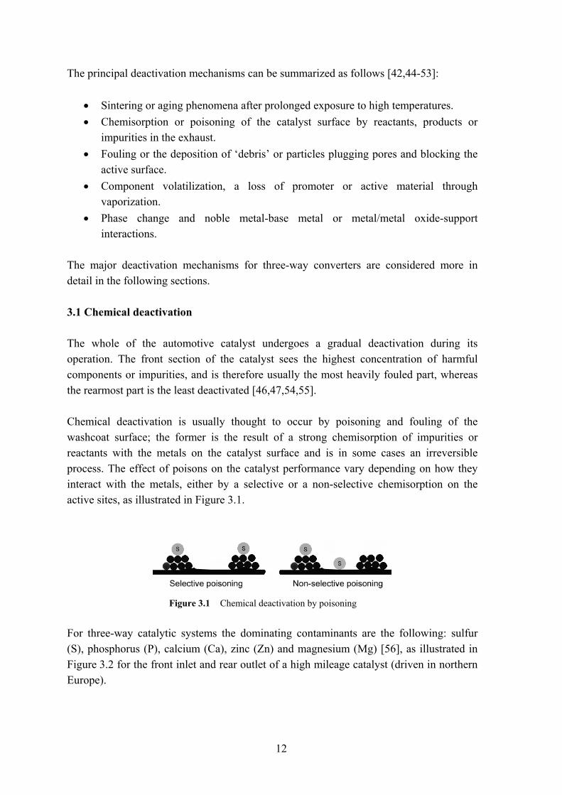
interactions. The major deactivation mechanisms for three-way converters are considered more in detail in the following sections. 3.1 Chemical deactivation The whole of the automotive catalyst undergoes a gradual deactivation during its operation. The front section of the catalyst sees the highest concentration of harmful components or impurities, and is therefore usually the most heavily fouled part, whereas the rearmost part is the least deactivated [46,47,54,55]. Chemical deactivation is usually thought to occur by poisoning and fouling of the washcoat surface; the former is the result of a strong chemisorption of impurities or reactants with the metals on the catalyst surface and is in some cases an irreversible process. The effect of poisons on the catalyst performance vary depending on how they interact with the metals, either by a selective or a non-selective chemisorption on the active sites, as illustrated in Figure 3.1.
Figure 3.1 Chemical deactivation by poisoning
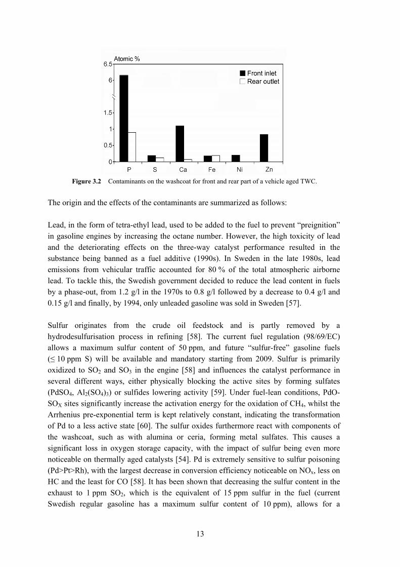
For three-way catalytic systems the dominating contaminants are the following: sulfur (S), phosphorus (P), calcium (Ca), zinc (Zn) and magnesium (Mg) [56], as illustrated in Figure 3.2 for the front inlet and rear outlet of a high mileage catalyst (driven in northern Europe).
13
Figure 3.2 Contaminants on the washcoat for front and rear part of a vehicle aged TWC.
The origin and the effects of the contaminants are summarized as follows: Lead, in the form of tetra-ethyl lead, used to be added to the fuel to prevent “preignition” in gasoline engines by increasing the octane number. However, the high toxicity of lead and the deteriorating effects on the three-way catalyst performance resulted in the substance being banned as a fuel additive (1990s). In Sweden in the late 1980s, lead emissions from vehicular traffic accounted for 80 % of the total atmospheric airborne lead. To tackle this, the Swedish government decided to reduce the lead content in fuels by a phase-out, from 1.2 g/l in the 1970s to 0.8 g/l followed by a decrease to 0.4 g/l and 0.15 g/l and finally, by 1994, only unleaded gasoline was sold in Sweden [57]. Sulfur originates from the crude oil feedstock and is partly removed by a hydrodesulfurisation process in refining [58]. The current fuel regulation (98/69/EC) allows a maximum sulfur content of 50 ppm, and future “sulfur-free” gasoline fuels (≤ 10 ppm S) will be available and mandatory starting from 2009. Sulfur is primarily oxidized to SO2 and SO3 in the engine [58] and influences the catalyst performance in several different ways, either physically blocking the active sites by forming sulfates (PdSO4, Al2(SO4)3) or sulfides lowering activity [59]. Under fuel-lean conditions, PdO-SOX sites significantly increase the activation energy for the oxidation of CH4, whilst the Arrhenius pre-exponential term is kept relatively constant, indicating the transformation of Pd to a less active state [60]. The sulfur oxides furthermore react with components of the washcoat, such as with alumina or ceria, forming metal sulfates. This causes a significant loss in oxygen storage capacity, with the impact of sulfur being even more noticeable on thermally aged catalysts [54]. Pd is extremely sensitive to sulfur poisoning (Pd>Pt>Rh), with the largest decrease in conversion efficiency noticeable on NOx, less on HC and the least for CO [58]. It has been shown that decreasing the sulfur content in the exhaust to 1 ppm SO2, which is the equivalent of 15 ppm sulfur in the fuel (current Swedish regular gasoline has a maximum sulfur content of 10 ppm), allows for a
14
significant improvement of the catalyst activity under fuel-lean conditions or at catalyst temperatures above 700 °C, as the high temperature accelerates a decomposition of the sulfates [54,61,62] Phosphorus, attributable to combustion of the antiwear/antioxidant additive zinc dialkyldithiophosphate (ZDDP) in engine oil [63,64] is the pollutant present in the largest amount, followed by calcium and zinc (also both present as oil detergent additives). Deposition of phosphorous on the catalyst external surface is thought to occur according to a shell-progressive mechanism, where the fine pores are clogged at first, followed by a complete coverage [65]. Phosphorus has been found to react with Al and Ce as e.g. AlPO4, CePO4, CeP2O7 [64,66-68,Paper I], thus impairing the OSC. The effects of phosphorus on the OSC are, however, not as detrimental as those of sulfur [54]. Phosphorous is more adverse to the catalyst conversion efficiency [54], especially so for the lean HC and CO activity. A partial rejuvenation of the OSC for the phosphated Ce-Zr-O system occurs after calcination at 1000 °C, which sinters the CePO4 thus uncovering the CeO2 surface [68]. Phosphorus is also found in the catalyst as P2O5 [63] or as an impermeable glassy Zn phosphate or as an amorphous glaze such as Ca phosphate, which physically blocks the pores in the washcoat [56,64]. Other means by which foreign material can be transported to the catalyst is as debris from the engine or the exhaust gas manifold, e.g. iron. Some of these contaminants, foremost P, Zn and Ca, can be removed from the catalytic system by a weak acid-based treatment, relying on the solubility of the respective species in acid [46,47,69,70,Paper I-II].
3.2 Thermal deactivation The materials in a three-way catalyst converter will thermally degrade with time at temperatures exceeding 800 °C. The main reason is the increased mobility of surface and bulk metals, which is related to the partial pressures of the species present on the surface [29]. These effects are influenced by intrinsic properties (melting point, phase transformation) and extrinsic factors (water vapor pressure, oxygen pressure, impurities). For three-way converter applications, the exhaust gas composition is known to fluctuate between reducing and oxidizing conditions, where the latter accelerate thermal deactivation [71-73] as compared with the former. Here, the time-in-stream is of secondary importance in comparison to temperature and aging atmosphere. Crucial temperatures are the so-called Hüttig and Tamman temperatures, at one third and one half of the respective melting points of the materials [74]. At these temperatures, a restructuring of the washcoat surface and the bulk occurs. First, when the Hüttig temperature is reached, atoms at defects will become mobile. This is followed by bulk
15
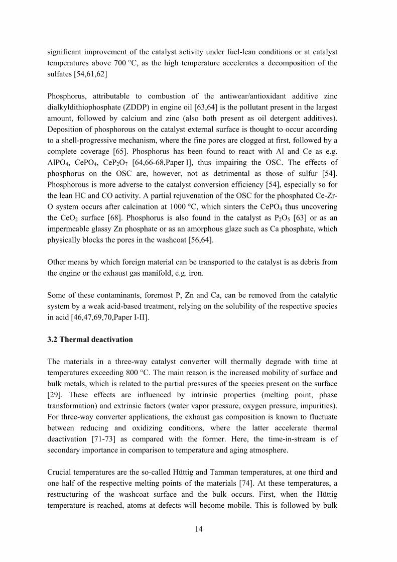
atoms exhibiting mobility at the Tamman temperature, and finally, once the melting point is reached, the mobility induces a liquid-phase behavior. Reduction of the active surface area, termed sintering, via agglomeration and coalescence of small crystallites into larger ones can occur either via crystallite migration or atomic migration. For the former, small crystallites are assumed to migrate on the support, collide and coalescence into larger crystallites. In the latter, atomic migration and interparticle transport of metal atoms from one crystallite to another via the surface or the gas phase are thought to lead to the loss of smaller crystallites and an increase in the larger ones [50,75,76], as can be inferred from Figure 3.3.
Figure 3.3 Schematic of the various stages in the formation and growth of metal particles: a) Vapor phase transport; b) Surface diffusion.
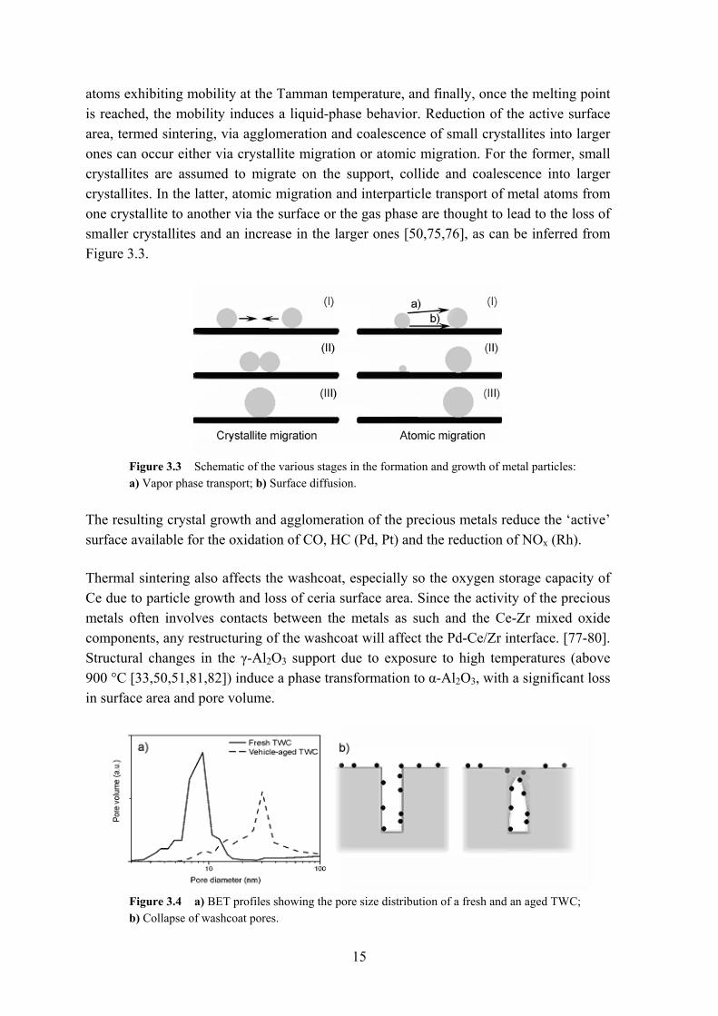
The resulting crystal growth and agglomeration of the precious metals reduce the ‘active’ surface available for the oxidation of CO, HC (Pd, Pt) and the reduction of NOx (Rh). Thermal sintering also affects the washcoat, especially so the oxygen storage capacity of Ce due to particle growth and loss of ceria surface area. Since the activity of the precious metals often involves contacts between the metals as such and the Ce-Zr mixed oxide components, any restructuring of the washcoat will affect the Pd-Ce/Zr interface. [77-80]. Structural changes in the γ-Al2O3 support due to exposure to high temperatures (above 900 °C [33,50,51,81,82]) induce a phase transformation to α-Al2O3, with a significant loss in surface area and pore volume.
Figure 3.4 a) BET profiles showing the pore size distribution of a fresh and an aged TWC; b) Collapse of washcoat pores.
16
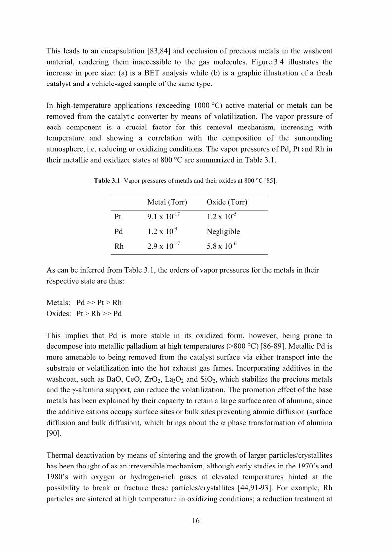
This leads to an encapsulation [83,84] and occlusion of precious metals in the washcoat material, rendering them inaccessible to the gas molecules. Figure 3.4 illustrates the increase in pore size: (a) is a BET analysis while (b) is a graphic illustration of a fresh catalyst and a vehicle-aged sample of the same type. In high-temperature applications (exceeding 1000 °C) active material or metals can be removed from the catalytic converter by means of volatilization. The vapor pressure of each component is a crucial factor for this removal mechanism, increasing with temperature and showing a correlation with the composition of the surrounding atmosphere, i.e. reducing or oxidizing conditions. The vapor pressures of Pd, Pt and Rh in their metallic and oxidized states at 800 °C are summarized in Table 3.1.
Table 3.1 Vapor pressures of metals and their oxides at 800 °C [85].
Metal (Torr) Oxide (Torr)
Pt 9.1 x 10⁻¹⁷ 1.2 x 10⁻⁵
Pd 1.2 x 10⁻⁹ Negligible
Rh 2.9 x 10⁻¹⁷ 5.8 x 10⁻⁶
As can be inferred from Table 3.1, the orders of vapor pressures for the metals in their respective state are thus: Metals: Pd >> Pt > Rh Oxides: Pt > Rh >> Pd This implies that Pd is more stable in its oxidized form, however, being prone to decompose into metallic palladium at high temperatures (>800 °C) [86-89]. Metallic Pd is more amenable to being removed from the catalyst surface via either transport into the substrate or volatilization into the hot exhaust gas fumes. Incorporating additives in the washcoat, such as BaO, CeO, ZrO2, La2O2 and SiO2, which stabilize the precious metals and the γ-alumina support, can reduce the volatilization. The promotion effect of the base metals has been explained by their capacity to retain a large surface area of alumina, since the additive cations occupy surface sites or bulk sites preventing atomic diffusion (surface diffusion and bulk diffusion), which brings about the α phase transformation of alumina [90]. Thermal deactivation by means of sintering and the growth of larger particles/crystallites has been thought of as an irreversible mechanism, although early studies in the 1970’s and 1980’s with oxygen or hydrogen-rich gases at elevated temperatures hinted at the possibility to break or fracture these particles/crystallites [44,91-93]. For example, Rh particles are sintered at high temperature in oxidizing conditions; a reduction treatment at

17
high temperatures, however, can redisperse the metal [94]. Redispersion is the reverse process of sintering, and entails a reduction of the particle size by the formation of mobile species. The introduction of a halogen (e.g. chlorine) accelerates the redispersion rate due to lowering of the vapor pressure of the metal by the formation of an oxy-chlorine intermediate [95-99]. This yields a more ‘rapid’ and ‘aggressive’ procedure for treating catalysts, in comparison with applying air or hydrogen regeneration only.

18
19
4 Experimental set-up Regeneration experiments were carried out at KTH, whilst the catalyst performance was evaluated in collaboration with a Swedish engine test company (AVL-MTC) using a mini-cuts reactor, running on real exhaust gases sampled from vehicles (idling or running engine). This set-up enabled the screening of a large number of catalysts under both stationary and transient conditions. For the tests small cylindrical samples (radius 20 mm; height 30 mm) were cut from commercial cordierite honeycomb type catalysts. 4.1 Catalysts Ford Spain and Fevar, a Belgian scrap yard company, supplied the commercial catalysts. Both, together with KTH, were involved in the European Union-funded Regencats project (2001-2004). The supplied catalysts covered driving conditions ranging from extra-urban to urban in countries such as Spain, Belgium and Finland. Unused (fresh) samples of each catalyst type allowed for comparative characterization and activity studies. To accommodate for variations in degree of pollution and aging as well as noble metal loading, the monolith fragments were divided into four separate parts: front inlet (Fi); front outlet (Fo); rear inlet (Ri); rear outlet (Ro). The aging is expressed as a mileage in thousands of km, e.g. for a front inlet catalyst, aged for 30 000 km, the abbreviation would be Fi30. 4.2 KTH equipment set-up (Regeneration) A tubular stainless steel reactor, with an internal diameter of 22 mm, was used for all regeneration experiments. This steel reactor was placed in a heating furnace, capable of attaining temperatures in excess of 700 °C. In short, regeneration measurements were
20
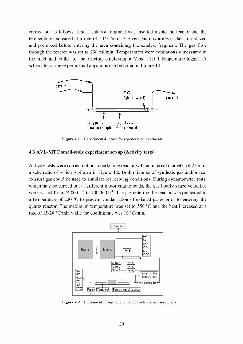
carried out as follows: first, a catalyst fragment was inserted inside the reactor and the temperature increased at a rate of 10 °C/min. A given gas mixture was then introduced and premixed before entering the area containing the catalyst fragment. The gas flow through the reactor was set to 230 ml/min. Temperatures were continuously measured at the inlet and outlet of the reactor, employing a Vips TT100 temperature-logger. A schematic of the experimental apparatus can be found in Figure 4.1.
Figure 4.1 Experimental set-up for regeneration treatments.
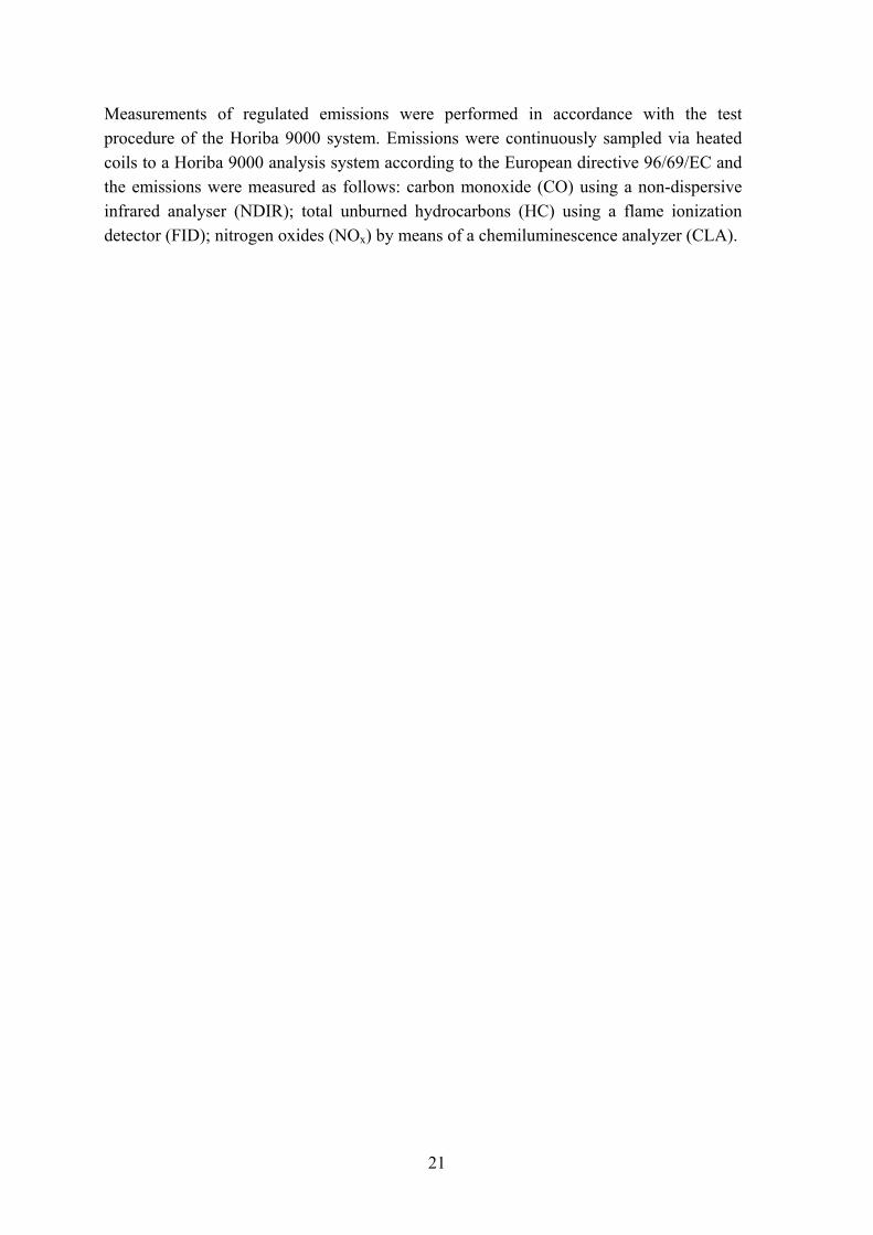
4.3 AVL-MTC small-scale experiment set-up (Activity tests) Activity tests were carried out in a quartz tube reactor with an internal diameter of 22 mm, a schematic of which is shown in Figure 4.2. Both mixtures of synthetic gas and/or real exhaust gas could be used to simulate real driving conditions. During dynamometer tests, which may be carried out at different motor engine loads, the gas hourly space velocities were varied from 24 000 h-1 to 100 000 h-1. The gas entering the reactor was preheated to a temperature of 220 °C to prevent condensation of exhaust gases prior to entering the quartz reactor. The maximum temperature was set to 550 °C and the heat increased at a rate of 15-20 °C/min while the cooling rate was 10 °C/min.
Figure 4.2 Equipment set-up for small-scale activity measurements
21
Measurements of regulated emissions were performed in accordance with the test procedure of the Horiba 9000 system. Emissions were continuously sampled via heated coils to a Horiba 9000 analysis system according to the European directive 96/69/EC and the emissions were measured as follows: carbon monoxide (CO) using a non-dispersive infrared analyser (NDIR); total unburned hydrocarbons (HC) using a flame ionization detector (FID); nitrogen oxides (NOx) by means of a chemiluminescence analyzer (CLA).

22
23
5 Characterization of three-way catalysts Jöns Jacob Berzelius introduced the concept of catalysis in 1835 as a “substance to awaken affinities, which are asleep at a particular temperature, by their mere presence and not by their own affinity”. Around half a century later, in 1895, Wilhem Ostwald defined catalysts, as “Catalysts are substances, which change the velocity of a reaction without modification of the energy factors of the reaction” [100,101]. Since these chemical reactions occur on the surface of the catalyst, it is imperative to study and understand the properties, both physical and chemical, of the active ‘substance’. In three-way catalysis the active substances are Pd, Pt, Rh or combinations of these. The close contact or interaction with various stabilizing materials, such as Al, Ce, Zr, Ba, whose intrinsic properties alter and modify the chemical reactions, structural properties and kinetics, warrants a closer study of these materials as well. Principal methods to obtain information on the performance and structure of catalysts in general involve sophisticated analysis instruments (structural analysis) in tandem with studying the chemical reactions under various conditions, such as varying temperatures and atmospheres. Foremost among these methods in heterogeneous catalysis is the examination and evaluation of the light-off behavior, i.e. the temperature at which a reaction is initiated and terminated (activity analysis). Structural analysis ensures the understanding of bulk, particle and surface properties, including factors such as composition, structure, surface area and noble metal dispersion. For this purpose a wide variety of characterization techniques have been utilized, some of which are outlined here.
24
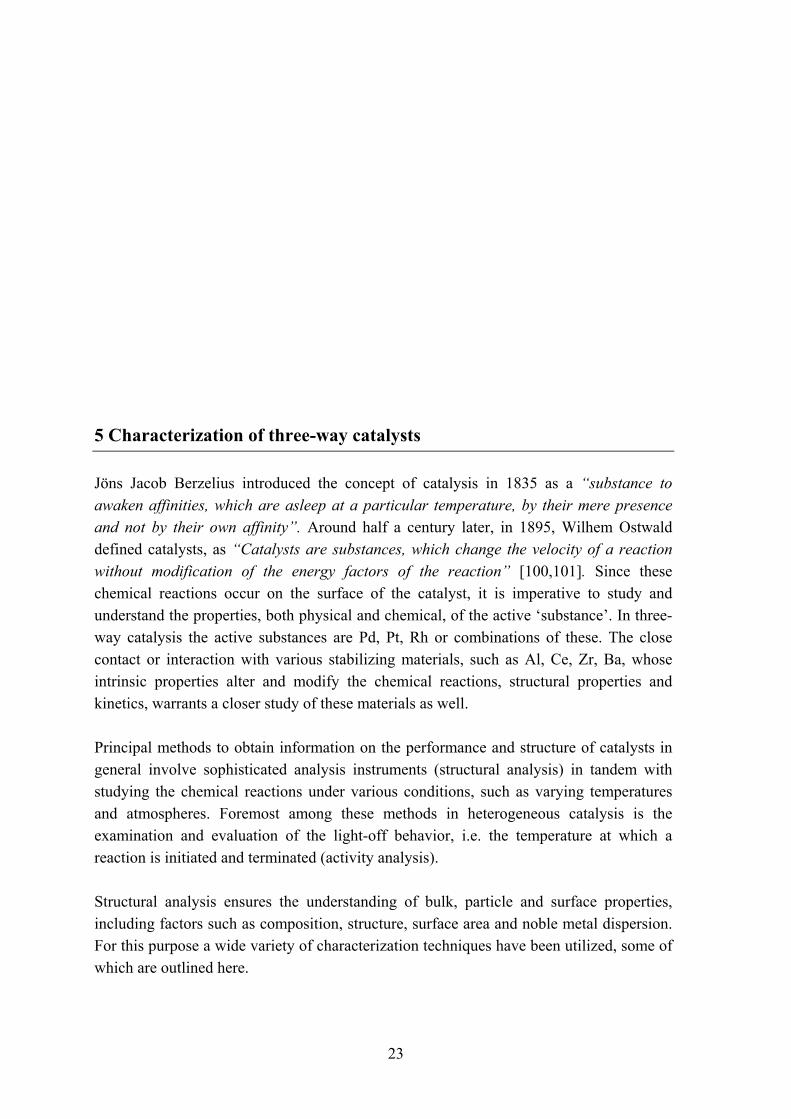
5.1 Scanning Electron Microscopy (SEM) and Energy Dispersive X-ray Spectroscopy (EDX) Surface phase morphology such as particle size, distribution and shape, is usually studied by means of the SEM/EDX technique. The SEM instrument scans a small sample surface with a probe comprising electrons (5-50 kV). The backscattered or emitted electrons from the sample are collected and further processed, resulting in an image on a cathode-ray tube. The order of magnification amounts to around 20 000-50 000; depending on sample composition a resolution of length scales down to 5 nm is possible. The elemental composition of the catalyst surface can be examined with an EDX. A typical SEM micrograph showing the cordierite and the washcoat is presented in Figure 5.1 (a), as well as the elemental composition of the washcoat (b).
Figure 5.1 a) SEM image of a TWC monolith; b) Elemental composition of the washcoat.
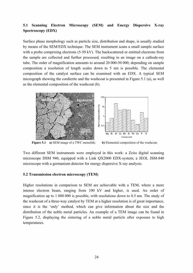
Two different SEM instruments were employed in this work: a Zeiss digital scanning microscope DSM 940, equipped with a Link QX2000 EDX-system; a JEOL JSM-840 microscope with a germanium detector for energy dispersive X-ray analysis. 5.2 Transmission electron microscopy (TEM) Higher resolutions in comparison to SEM are achievable with a TEM, where a more intense electron beam, ranging from 100 kV and higher, is used. An order of magnification up to 1 000 000 is possible, with resolutions down to 0.5 nm. The study of the washcoat of a three-way catalyst by TEM at a higher resolution is of great importance, since it is the ‘only’ method, which can give information about the size and the distribution of the noble metal particles. An example of a TEM image can be found in Figure 5.2, displaying the sintering of a noble metal particle after exposure to high temperatures.
25
Figure 5.2 TEM micrographs of catalysts: (left) fresh catalyst and (right) aged.
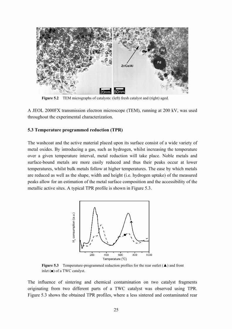
A JEOL 2000FX transmission electron microscope (TEM), running at 200 kV, was used throughout the experimental characterization. 5.3 Temperature programmed reduction (TPR) The washcoat and the active material placed upon its surface consist of a wide variety of metal oxides. By introducing a gas, such as hydrogen, whilst increasing the temperature over a given temperature interval, metal reduction will take place. Noble metals and surface-bound metals are more easily reduced and thus their peaks occur at lower temperatures, whilst bulk metals follow at higher temperatures. The ease by which metals are reduced as well as the shape, width and height (i.e. hydrogen uptake) of the measured peaks allow for an estimation of the metal surface composition and the accessibility of the metallic active sites. A typical TPR profile is shown in Figure 5.3.
Figure 5.3 Temperature-programmed reduction profiles for the rear outlet (▲) and front inlet (■) of a TWC catalyst.
The influence of sintering and chemical contamination on two catalyst fragments originating from two different parts of a TWC catalyst was observed using TPR. Figure 5.3 shows the obtained TPR profiles, where a less sintered and contaminated rear
26
outlet (Ro30) is compared with the front inlet (Fi30) from the same catalyst. The loss of hydrogen uptake and the higher temperatures required to reduce the surface and noble metals (<500 °C) for the front inlet are noteworthy. In addition, TPR combined with chemisorption experiments, where a gas such as carbon monoxide (CO) is pulsed in small amounts over the sample, allows for an estimation of the metal dispersion. 5.4 Chemisorption analysis Dispersion defines the fraction or the amount of active atoms on the catalyst. For Pd, Pt and Rh metals the surface concentration is readily measured by means of chemisorption experiments with adsorbate gases such as H2 or CO forming a monolayer on the precious metals. Volumetric adsorption of CO was carried out at room temperature using a Micromeritics Autochem TPD/TPR 2910, whilst the H2 chemisorption was determined at 90 °C using a Carlo Erba Instruments 1900. Here, the amount of reversibly adsorbed H2 was determined by the back adsorption method proposed by Benson et al. [102]. The dispersion is estimated by assuming a certain stoichiometry between adsorbate gas and precious metals; this in turn is also the method’s main weakness, the reason being a spillover phenomenon between the noble metal and the adjacent support material (CeO2, Ce-Zr oxide) [103], causing H2 to diffuse to the washcoat and thereby overestimating the ‘real’ noble metal dispersion. The spillover can be reduced by controlling (lowering) the adsorbate temperature [104,105] used during the experiment. For the CO and the H2 chemisorption measurements, a 1:1 ratio for CO and H2 and surface precious metals was assumed. 5.5 Brunauer, Emmet and Teller analysis (BET) Measurements of pore size distribution and surface area of small monolith cylinders (radius 12 mm; height 30 mm) were obtained with a Micromeritics ASAP 2010 instrument. Adsorption/desorption of nitrogen at liquid nitrogen temperature (-196 °C) was used. Several BET analyses were carried out on whole monoliths a priori and a posteriori to thermal gas treatment in order to compare the efficacy of the regeneration methods. 5.6 X-Ray Diffraction (XRD) X-ray Diffraction (XRD) is a powerful non-destructive technique for characterizing crystalline materials. It provides information on structures, phases, preferred crystal orientations (texture) and other structural parameters such as average grain size, crystallinity, strain and crystal defects. XRD furthermore allows for studies of the composition of the bulk structure, as the high energy of the x-ray beam is able to penetrate
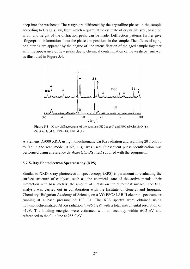
27
deep into the washcoat. The x-rays are diffracted by the crystalline phases in the sample according to Bragg’s law, from which a quantitative estimate of crystallite size, based on width and height of the diffraction peak, can be made. Diffraction patterns further give ‘fingerprint’ information about the phase compositions in the sample. The effects of aging or sintering are apparent by the degree of line intensification of the aged sample together with the appearance of new peaks due to chemical contamination of the washcoat surface, as illustrated in Figure 5.4.
Figure 5.4 X-ray diffractograms of the catalysts Fi30 (aged) and Fi00 (fresh): ZrO (■), Zr1-xCexO2 (▲), CePO4 (●) and Pd (+).
A Siemens D5000 XRD, using monochromatic Cu Kα radiation and scanning 2θ from 30 to 80° in the scan mode (0.02°, 1 s), was used. Subsequent phase identification was performed using a reference database (JCPDS files) supplied with the equipment. 5.7 X-Ray Photoelectron Spectroscopy (XPS) Similar to XRD, x-ray photoelectron spectroscopy (XPS) is paramount in evaluating the surface structure of catalysts, such as: the chemical state of the active metals; their interaction with base metals; the amount of metals on the outermost surface. The XPS analysis was carried out in collaboration with the Institute of General and Inorganic Chemistry, Bulgarian Academy of Science, on a VG ESCALAB II electron spectrometer running at a base pressure of 10-8 Pa. The XPS spectra were obtained using non-monochromatized Al Kα radiation (1486.6 eV) with a total instrumental resolution of ~1eV. The binding energies were estimated with an accuracy within ±0.2 eV and referenced to the C1 s line at 285.0 eV.
28
5.8 Laser Ablation (LA) Laser ablation allows for the analysis of metals and contaminants located on the surface as well as in the ‘bulk-material’ of the washcoat. This is achieved by employing a high-performance Nd:YAG laser, which ‘ablates’ components from the catalyst. The ablation depth can be varied, e.g. between 1 µm and 10 µm, enabling the study of the metal or contaminant composition or concentration at various depths in the washcoat. The ablated material is carried via an inert gas to an ICPMS instrument and analyzed accordingly. The Laser ablation analysis was carried out at the Laboratory of Analytical Chemistry, Åbo Akademi University, on a UP-213 (New Wave Research) Laser Ablation unit coupled to an Elan 6100 quadropole ICPMS instrument.
29
6 Investigation of regeneration procedures for TWC Several methods to reinvigorate vehicle-aged commercial three way catalysts were investigated. Applying weak organic acids dissolved contaminants accumulated on the active surface; the contaminant ions were subsequently removed from the solutions by complexation (Papers II, III). Redispersion of sintered larger metal crystallites was also attempted by means of various thermal gaseous treatments, thus partly restoring the active noble metal area (Papers I, II, IV). The first procedures in this work comprised thermal gas treatments in oxygen or hydrogen-rich atmospheres, at temperatures ranging from 300 °C to 700 °C. The effect of temperature and treatment time on the stability of the noble metal and metal oxide support particles was evaluated. Based on these experiments and the conclusions that could be drawn, it was hypothesized that the addition of chlorine, either in liquid or gaseous form, might enhance regeneration of the catalysts. Subsequent experiments with a chlorine-rich environment confirmed this hypothesis and full-scale experiments (Paper IV) were initiated. Real simulated driving conditions allowed for rigorous testing and evaluation of the proposed regeneration method. Since deactivation of catalysts is not solely the result of thermal sintering, and the associated decrease in active surface area, but also due to poisoning and blocking of the active sites as well as loss of OSC, regeneration targeting the removal of these contaminants was investigated in combination with a thermal gas treatment or a wet chemical treatment (Papers II, III). 6.1. Thermal gas treatments (Papers I, II) Regaining lost activity stemming from thermal deactivation, through which metals have undergone structural changes inducing large and bulky crystallite structures, is not ‘easy’ by any means. Complex metal compositions found in a TWC, placed there to uphold a
30
stable and high catalytic activity in a harsh exhaust gas environment, make a ‘successful’ regeneration more difficult. Experiments were based on how parameters such as treatment temperature, time and gas composition would influence the washcoat material as well as the precious metals placed thereon. These experiments were performed to identify potential regeneration methods. From the obtained results, the following conclusions can be drawn:
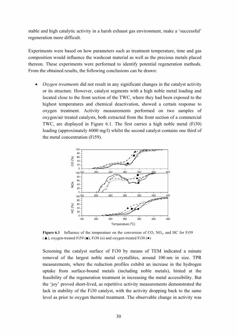
• Oxygen treatments did not result in any significant changes in the catalyst activity or its structure. However, catalyst segments with a high noble metal loading and located close to the front section of the TWC, where they had been exposed to the highest temperatures and chemical deactivation, showed a certain response to oxygen treatment. Activity measurements performed on two samples of oxygen/air treated catalysts, both extracted from the front section of a commercial TWC, are displayed in Figure 6.1. The first carries a high noble metal (Fi30) loading (approximately 6000 mg/l) whilst the second catalyst contains one third of the metal concentration (Fi59).
Figure 6.1 Influence of the temperature on the conversion of CO, NOx, and HC for Fi59 (▲), oxygen-treated Fi59 (■), Fi30 (ο) and oxygen-treated Fi30 (●)
Screening the catalyst surface of Fi30 by means of TEM indicated a minute
removal of the largest noble metal crystallites, around 100 nm in size. TPR measurements, where the reduction profiles exhibit an increase in the hydrogen uptake from surface-bound metals (including noble metals), hinted at the feasibility of the regeneration treatment in increasing the metal accessibility. But the ‘joy’ proved short-lived, as repetitive activity measurements demonstrated the lack in stability of the Fi30 catalyst, with the activity dropping back to the same level as prior to oxygen thermal treatment. The observable change in activity was
31
thus most likely due to a temporary ‘cleaning’ effect of the washcoat surface (e.g. the removal of S compounds).
• Hydrogen treatment. Changing the treatment gas to hydrogen, whilst retaining the same temperature and time intervals as during the oxygen treatment, did not give rise to any detectable changes in the catalysts. A loss in activity was even observable at temperatures higher than 700 °C, comparable with similar loss in activity for oxygen-treated catalysts in the same treatment temperature interval.
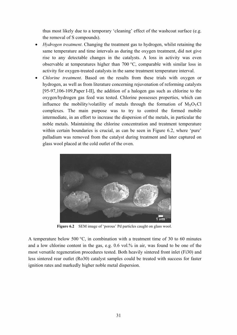
• Chlorine treatment. Based on the results from these trials with oxygen or hydrogen, as well as from literature concerning rejuvenation of reforming catalysts [95-97,106-109,Paper I-II], the addition of a halogen gas such as chlorine to the oxygen/hydrogen gas feed was tested. Chlorine possesses properties, which can influence the mobility/volatility of metals through the formation of MXOYCl complexes. The main purpose was to try to control the formed mobile intermediate, in an effort to increase the dispersion of the metals, in particular the noble metals. Maintaining the chlorine concentration and treatment temperature within certain boundaries is crucial, as can be seen in Figure 6.2, where ‘pure’ palladium was removed from the catalyst during treatment and later captured on glass wool placed at the cold outlet of the oven.
Figure 6.2 SEM image of ‘porous’ Pd particles caught on glass wool.
A temperature below 500 °C, in combination with a treatment time of 30 to 60 minutes and a low chlorine content in the gas, e.g. 0.6 vol.% in air, was found to be one of the most versatile regeneration procedures tested. Both heavily sintered front inlet (Fi30) and less sintered rear outlet (Ro30) catalyst samples could be treated with success for faster ignition rates and markedly higher noble metal dispersion.
32
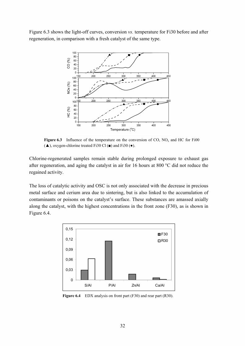
Figure 6.3 shows the light-off curves, conversion vs. temperature for Fi30 before and after regeneration, in comparison with a fresh catalyst of the same type.
Figure 6.3 Influence of the temperature on the conversion of CO, NOx and HC for Fi00 (▲), oxygen-chlorine treated Fi30 Cl (■) and Fi30 (●).
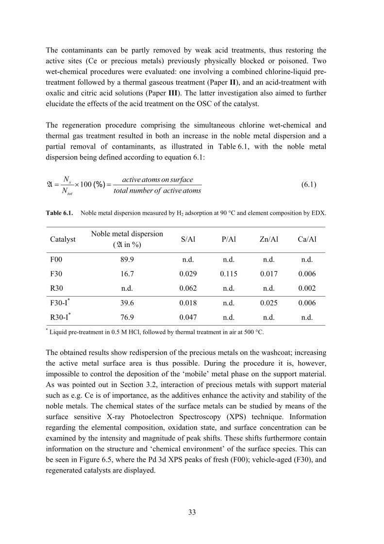
Chlorine-regenerated samples remain stable during prolonged exposure to exhaust gas after regeneration, and aging the catalyst in air for 16 hours at 800 °C did not reduce the regained activity. The loss of catalytic activity and OSC is not only associated with the decrease in precious metal surface and cerium area due to sintering, but is also linked to the accumulation of contaminants or poisons on the catalyst’s surface. These substances are amassed axially along the catalyst, with the highest concentrations in the front zone (F30), as is shown in Figure 6.4.
0
0,03
0,06
0,09
0,12
0,15
S/Al P/Al Zn/Al Ca/Al
F30
R30
Figure 6.4 EDX analysis on front part (F30) and rear part (R30).
33
The contaminants can be partly removed by weak acid treatments, thus restoring the active sites (Ce or precious metals) previously physically blocked or poisoned. Two wet-chemical procedures were evaluated: one involving a combined chlorine-liquid pre-treatment followed by a thermal gaseous treatment (Paper II), and an acid-treatment with oxalic and citric acid solutions (Paper III). The latter investigation also aimed to further elucidate the effects of the acid treatment on the OSC of the catalyst. The regeneration procedure comprising the simultaneous chlorine wet-chemical and thermal gas treatment resulted in both an increase in the noble metal dispersion and a partial removal of contaminants, as illustrated in Table 6.1, with the noble metal dispersion being defined according to equation 6.1:
100 (%)s
tot
N active atoms on surfaceN total number of active atoms
= × =A (6.1)
Table 6.1. Noble metal dispersion measured by H2 adsorption at 90 °C and element composition by EDX.
Catalyst Noble metal dispersion
(A in %) S/Al P/Al Zn/Al Ca/Al
F00 89.9 n.d. n.d. n.d. n.d.
F30 16.7 0.029 0.115 0.017 0.006
R30 n.d. 0.062 n.d. n.d. 0.002
F30-I* 39.6 0.018 n.d. 0.025 0.006
R30-I* 76.9 0.047 n.d. n.d. n.d.
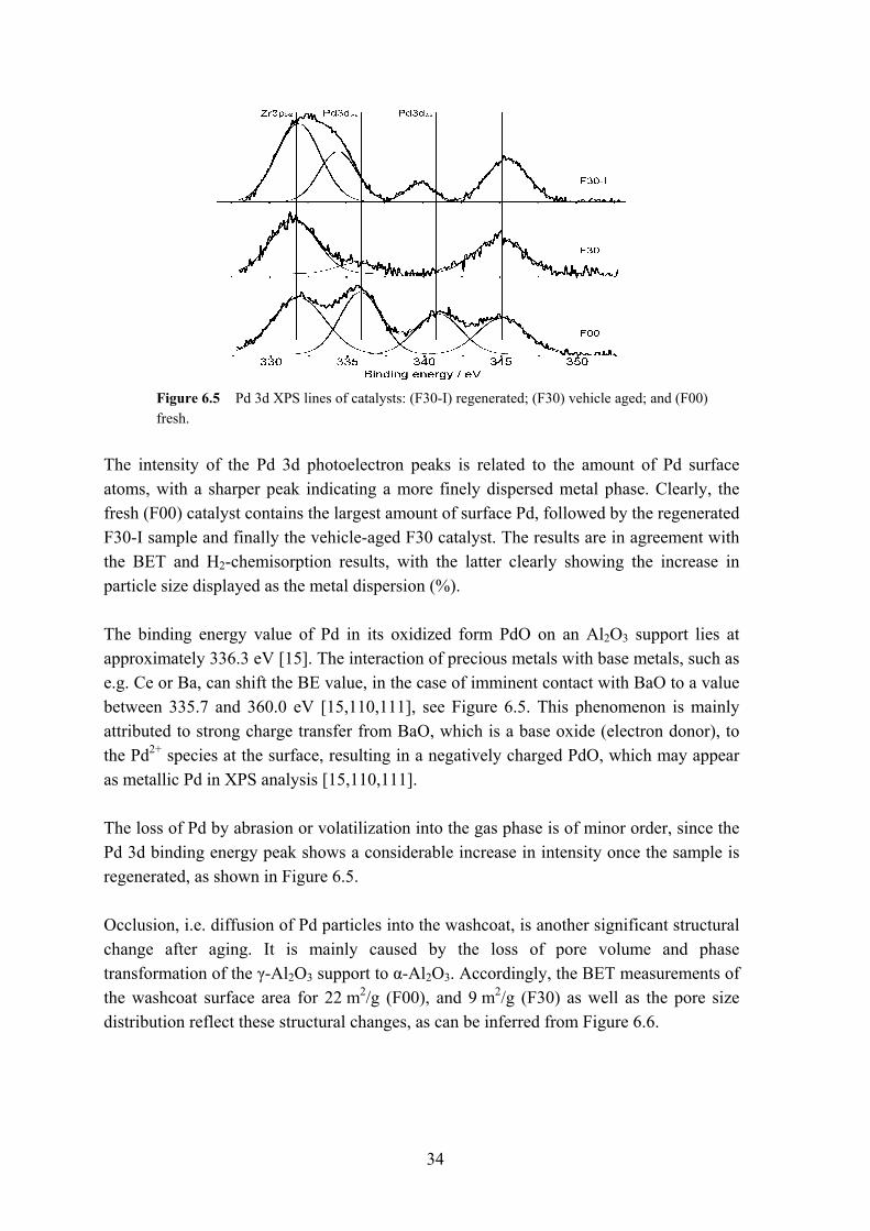
* Liquid pre-treatment in 0.5 M HCl, followed by thermal treatment in air at 500 °C. The obtained results show redispersion of the precious metals on the washcoat; increasing the active metal surface area is thus possible. During the procedure it is, however, impossible to control the deposition of the ‘mobile’ metal phase on the support material. As was pointed out in Section 3.2, interaction of precious metals with support material such as e.g. Ce is of importance, as the additives enhance the activity and stability of the noble metals. The chemical states of the surface metals can be studied by means of the surface sensitive X-ray Photoelectron Spectroscopy (XPS) technique. Information regarding the elemental composition, oxidation state, and surface concentration can be examined by the intensity and magnitude of peak shifts. These shifts furthermore contain information on the structure and ‘chemical environment’ of the surface species. This can be seen in Figure 6.5, where the Pd 3d XPS peaks of fresh (F00); vehicle-aged (F30), and regenerated catalysts are displayed.
34
Figure 6.5 Pd 3d XPS lines of catalysts: (F30-I) regenerated; (F30) vehicle aged; and (F00) fresh.
The intensity of the Pd 3d photoelectron peaks is related to the amount of Pd surface atoms, with a sharper peak indicating a more finely dispersed metal phase. Clearly, the fresh (F00) catalyst contains the largest amount of surface Pd, followed by the regenerated F30-I sample and finally the vehicle-aged F30 catalyst. The results are in agreement with the BET and H2-chemisorption results, with the latter clearly showing the increase in particle size displayed as the metal dispersion (%). The binding energy value of Pd in its oxidized form PdO on an Al2O3 support lies at approximately 336.3 eV [15]. The interaction of precious metals with base metals, such as e.g. Ce or Ba, can shift the BE value, in the case of imminent contact with BaO to a value between 335.7 and 360.0 eV [15,110,111], see Figure 6.5. This phenomenon is mainly attributed to strong charge transfer from BaO, which is a base oxide (electron donor), to the Pd2+ species at the surface, resulting in a negatively charged PdO, which may appear as metallic Pd in XPS analysis [15,110,111]. The loss of Pd by abrasion or volatilization into the gas phase is of minor order, since the Pd 3d binding energy peak shows a considerable increase in intensity once the sample is regenerated, as shown in Figure 6.5. Occlusion, i.e. diffusion of Pd particles into the washcoat, is another significant structural change after aging. It is mainly caused by the loss of pore volume and phase transformation of the γ-Al2O3 support to α-Al2O3. Accordingly, the BET measurements of the washcoat surface area for 22 m2/g (F00), and 9 m2/g (F30) as well as the pore size distribution reflect these structural changes, as can be inferred from Figure 6.6.
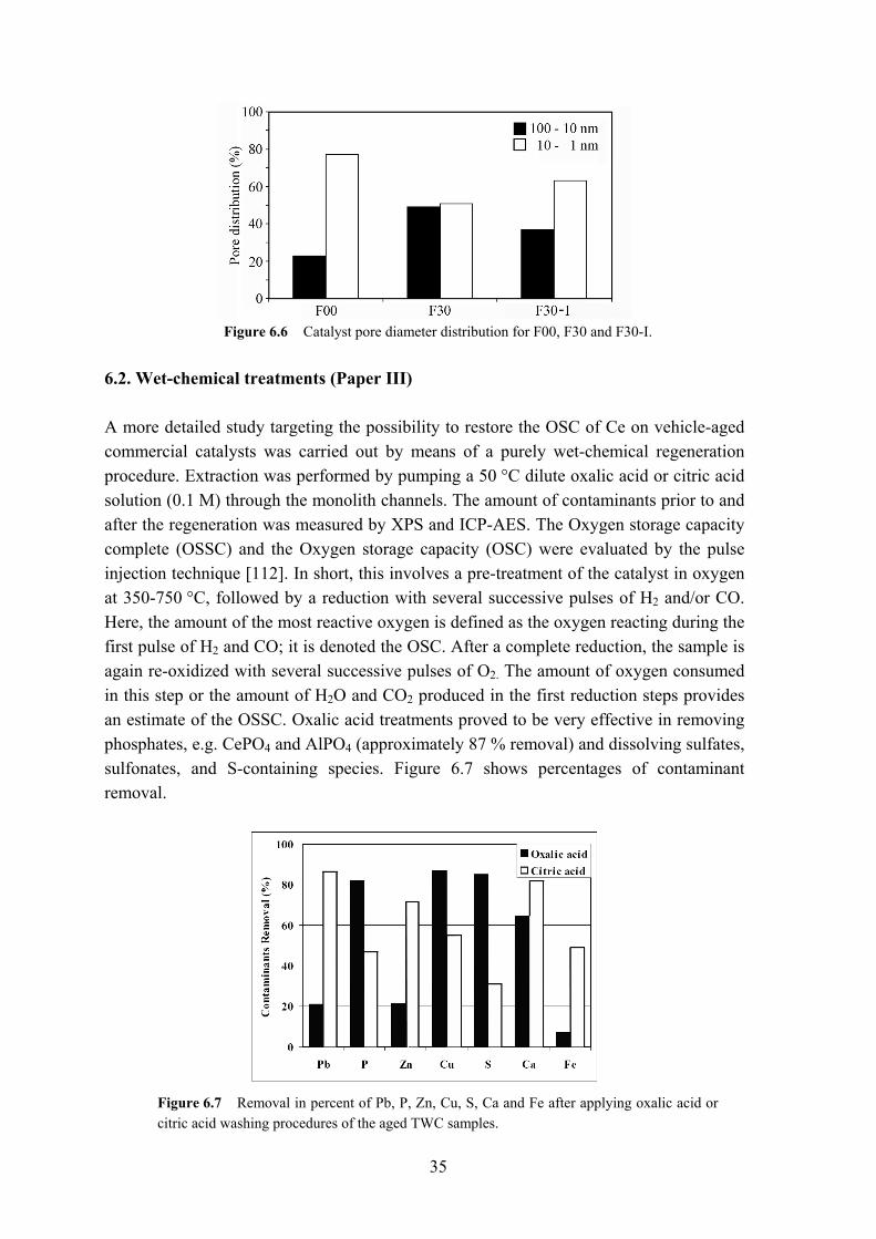
35
Figure 6.6 Catalyst pore diameter distribution for F00, F30 and F30-I.
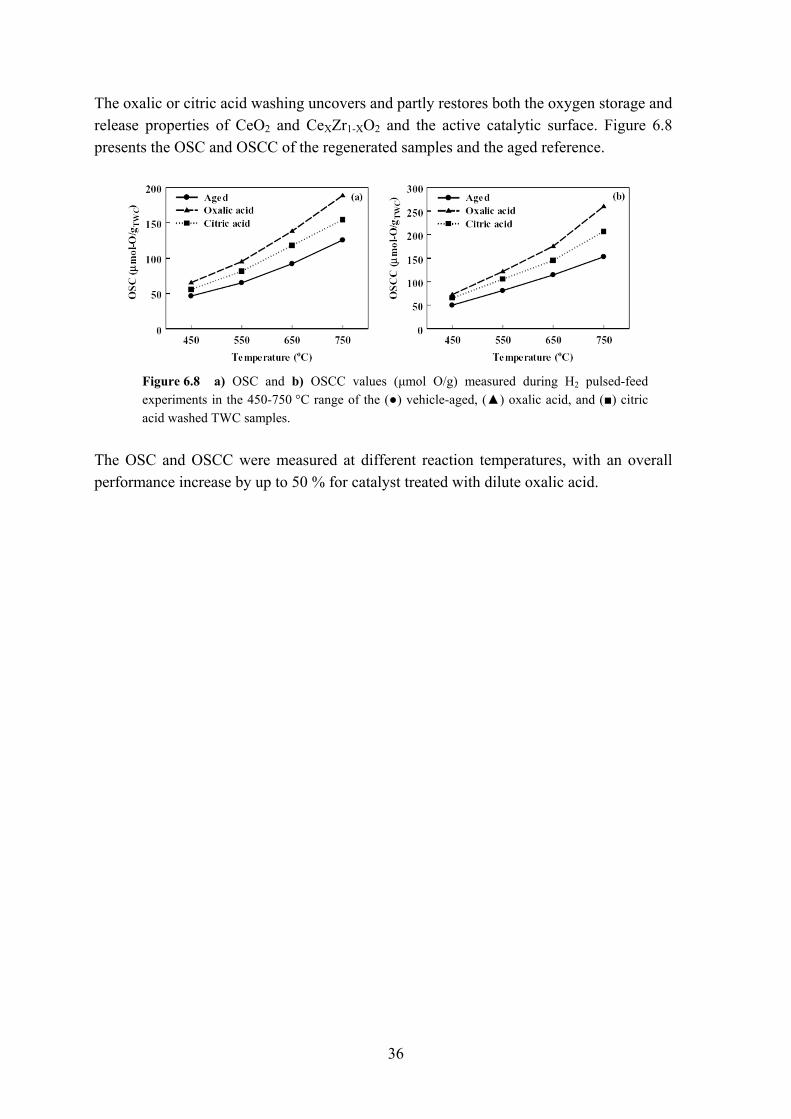
6.2. Wet-chemical treatments (Paper III) A more detailed study targeting the possibility to restore the OSC of Ce on vehicle-aged commercial catalysts was carried out by means of a purely wet-chemical regeneration procedure. Extraction was performed by pumping a 50 °C dilute oxalic acid or citric acid solution (0.1 M) through the monolith channels. The amount of contaminants prior to and after the regeneration was measured by XPS and ICP-AES. The Oxygen storage capacity complete (OSSC) and the Oxygen storage capacity (OSC) were evaluated by the pulse injection technique [112]. In short, this involves a pre-treatment of the catalyst in oxygen at 350-750 °C, followed by a reduction with several successive pulses of H2 and/or CO. Here, the amount of the most reactive oxygen is defined as the oxygen reacting during the first pulse of H2 and CO; it is denoted the OSC. After a complete reduction, the sample is again re-oxidized with several successive pulses of O2. The amount of oxygen consumed in this step or the amount of H2O and CO2 produced in the first reduction steps provides an estimate of the OSSC. Oxalic acid treatments proved to be very effective in removing phosphates, e.g. CePO4 and AlPO4 (approximately 87 % removal) and dissolving sulfates, sulfonates, and S-containing species. Figure 6.7 shows percentages of contaminant removal.
Figure 6.7 Removal in percent of Pb, P, Zn, Cu, S, Ca and Fe after applying oxalic acid or citric acid washing procedures of the aged TWC samples.
36
The oxalic or citric acid washing uncovers and partly restores both the oxygen storage and release properties of CeO2 and CeXZr1-XO2 and the active catalytic surface. Figure 6.8 presents the OSC and OSCC of the regenerated samples and the aged reference.
Figure 6.8 a) OSC and b) OSCC values (µmol O/g) measured during H2 pulsed-feed experiments in the 450-750 °C range of the (●) vehicle-aged, (▲) oxalic acid, and (■) citric acid washed TWC samples.
The OSC and OSCC were measured at different reaction temperatures, with an overall performance increase by up to 50 % for catalyst treated with dilute oxalic acid.
37
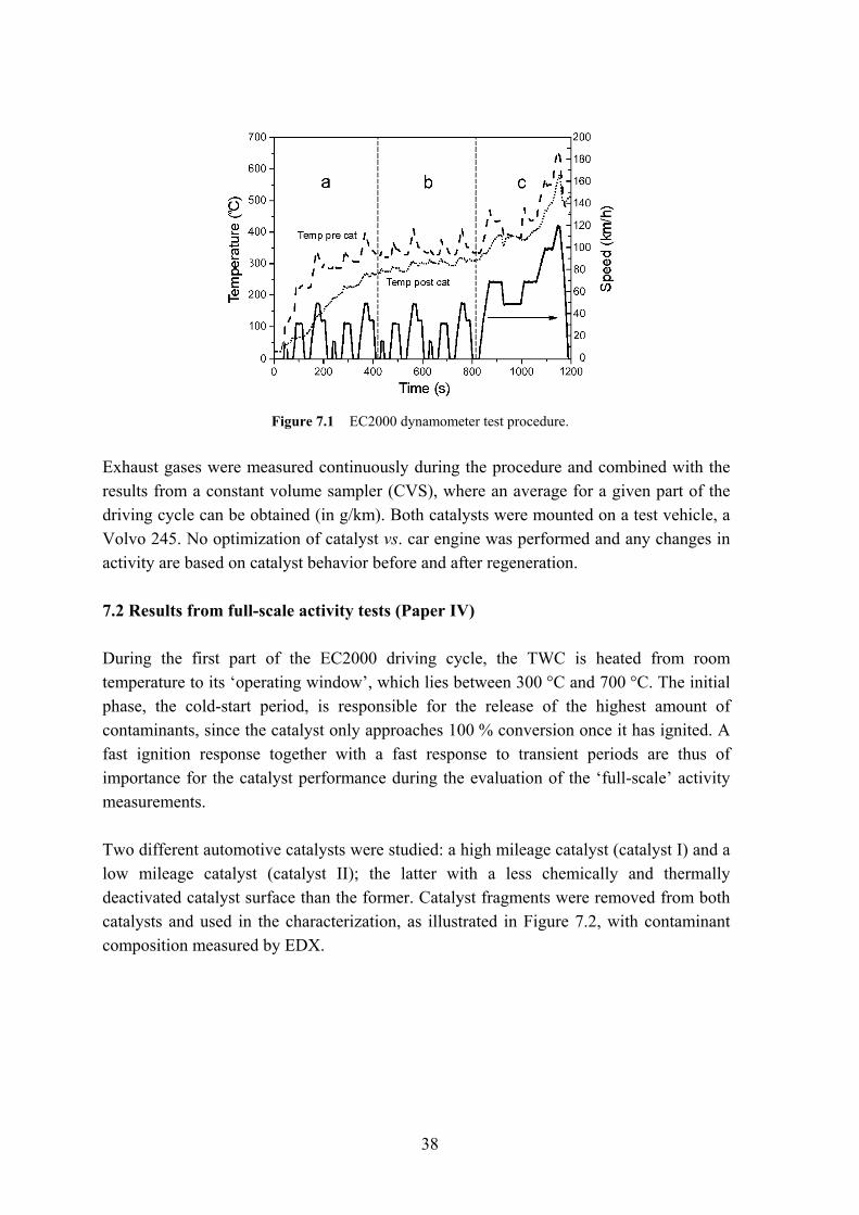
7 Regeneration of full scale TWC The current emission limits are prescribed in the Euro IV standard. An overview of the various Euro standards was presented in Table 1.1. The objective of the standards is to limit the average emission (g/km) of the regulated compounds. In order to assess a vehicle’s emissions, various test procedures have been implemented, of which the European Driving cycle (EC2000) was established by the EU. The test procedure is a compromise between real driving conditions and the repeated measurements in laboratory scale, emulating real driving conditions. The results are therefore highly dependent on how the tests and the cycle are applied. Before the year 2000 the emission sampling in the European cycle would start 40 seconds after cold start of a vehicle, thus not accounting for a large part of the emissions as well as failing to give an accurate estimate of actual vehicle emissions. 7.1 Full-scale activity tests Full-scale dynamometer tests allow for a more dynamic measurement of the catalyst activity than lab-scale tests. Here, factors such as varying exhaust gas composition and exhaust gas temperature are more easily studied in comparison to using fixed gas and temperature ramps, e.g. the ‘mini-cuts’ reactor. The applied test method EC2000 is standardized and consists of two parts: (a+b) the first 780 s representing urban driving conditions (UBC); (c) the final 400 s comprising a higher speed part, the so-called extra urban driving cycle (EUDC), as illustrated in Figure 7.1.
38
Figure 7.1 EC2000 dynamometer test procedure.
Exhaust gases were measured continuously during the procedure and combined with the results from a constant volume sampler (CVS), where an average for a given part of the driving cycle can be obtained (in g/km). Both catalysts were mounted on a test vehicle, a Volvo 245. No optimization of catalyst vs. car engine was performed and any changes in activity are based on catalyst behavior before and after regeneration. 7.2 Results from full-scale activity tests (Paper IV) During the first part of the EC2000 driving cycle, the TWC is heated from room temperature to its ‘operating window’, which lies between 300 °C and 700 °C. The initial phase, the cold-start period, is responsible for the release of the highest amount of contaminants, since the catalyst only approaches 100 % conversion once it has ignited. A fast ignition response together with a fast response to transient periods are thus of importance for the catalyst performance during the evaluation of the ‘full-scale’ activity measurements. Two different automotive catalysts were studied: a high mileage catalyst (catalyst I) and a low mileage catalyst (catalyst II); the latter with a less chemically and thermally deactivated catalyst surface than the former. Catalyst fragments were removed from both catalysts and used in the characterization, as illustrated in Figure 7.2, with contaminant composition measured by EDX.
39
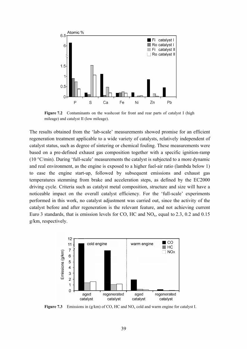
Figure 7.2 Contaminants on the washcoat for front and rear parts of catalyst I (high mileage) and catalyst II (low mileage).
The results obtained from the ‘lab-scale’ measurements showed promise for an efficient regeneration treatment applicable to a wide variety of catalysts, relatively independent of catalyst status, such as degree of sintering or chemical fouling. These measurements were based on a pre-defined exhaust gas composition together with a specific ignition-ramp (10 °C/min). During ‘full-scale’ measurements the catalyst is subjected to a more dynamic and real environment, as the engine is exposed to a higher fuel-air ratio (lambda below 1) to ease the engine start-up, followed by subsequent emissions and exhaust gas temperatures stemming from brake and acceleration steps, as defined by the EC2000 driving cycle. Criteria such as catalyst metal composition, structure and size will have a noticeable impact on the overall catalyst efficiency. For the ‘full-scale’ experiments performed in this work, no catalyst adjustment was carried out, since the activity of the catalyst before and after regeneration is the relevant feature, and not achieving current Euro 3 standards, that is emission levels for CO, HC and NOx, equal to 2.3, 0.2 and 0.15 g/km, respectively.
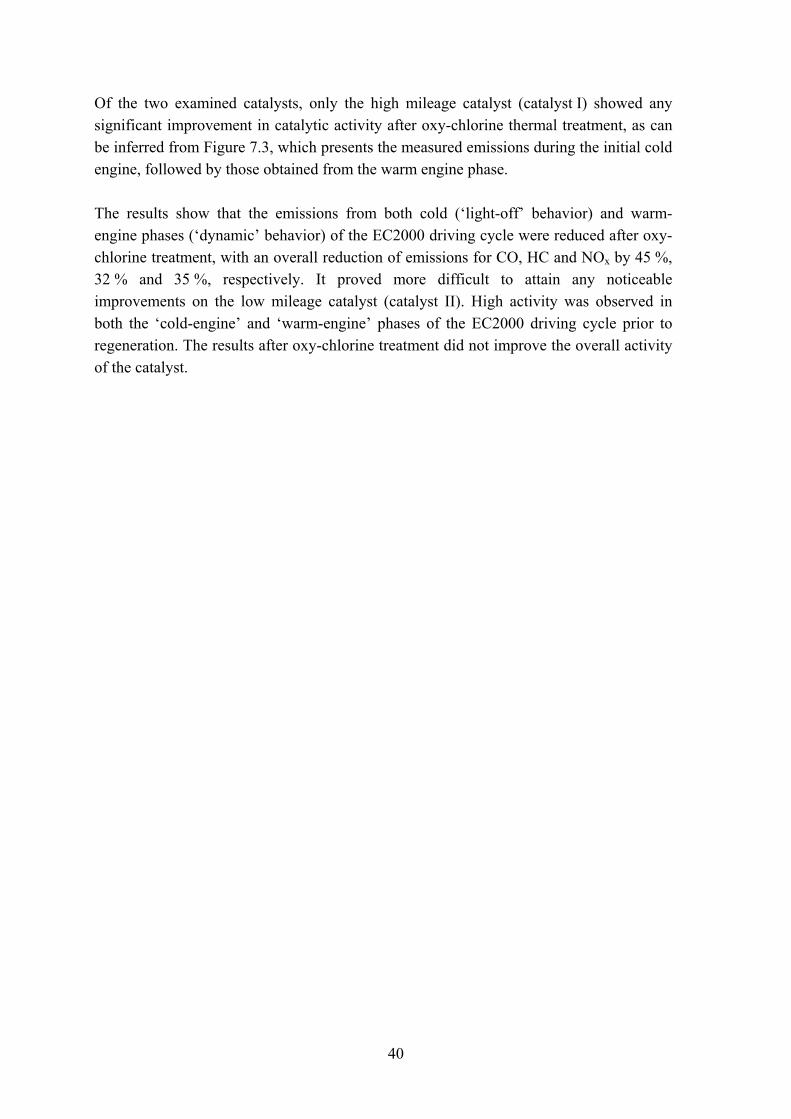
Figure 7.3 Emissions in (g/km) of CO, HC and NOx cold and warm engine for catalyst I.
40
Of the two examined catalysts, only the high mileage catalyst (catalyst I) showed any significant improvement in catalytic activity after oxy-chlorine thermal treatment, as can be inferred from Figure 7.3, which presents the measured emissions during the initial cold engine, followed by those obtained from the warm engine phase. The results show that the emissions from both cold (‘light-off’ behavior) and warm-engine phases (‘dynamic’ behavior) of the EC2000 driving cycle were reduced after oxy-chlorine treatment, with an overall reduction of emissions for CO, HC and NOx by 45 %, 32 % and 35 %, respectively. It proved more difficult to attain any noticeable improvements on the low mileage catalyst (catalyst II). High activity was observed in both the ‘cold-engine’ and ‘warm-engine’ phases of the EC2000 driving cycle prior to regeneration. The results after oxy-chlorine treatment did not improve the overall activity of the catalyst.
41
8 Mathematical analysis of oxy-chlorine regenerated TWC The last part of the thesis encompasses a kinetic (mathematical) model, which aims to capture the characteristics of a commercial three-way catalyst cartridge for three stages: fresh, vehicle-aged, and thermally oxy-chlorine regenerated under lab-scale conditions. The reaction kinetics are tuned to correctly describe the intrinsic properties (e.g. catalyst activity) of a fresh catalyst, followed by a study of the activities of the aged and regenerated catalysts. The model predictions are then validated and compared with the experimental findings. 8.1 Model description (Paper V) A plethora of models have appeared in literature addressing phenomena occurring in three-way catalysts with varying degree of success [113-126]. The herein presented mathematical model draws upon the findings in terms of modeling of the physics and reaction kinetics in previous work, with the purpose to study the impact of regeneration on a local and global level in the monolith. The model was solved with the commercial finite-element solver Comsol 3.1. The model takes into account conservation of mass, momentum, energy and species for the monolith, as well as accounting for thermal and chemical non-equilibrium between the solid and gas phase, and the chemical reactions of six key species are considered, viz. carbon monoxide (CO), hydrocarbons (HC) divided into the two subgroups quickly and slowly oxidizing species, nitrogen oxide (NO), hydrogen (H2) and oxygen (O2). These are the main species involved in the oxidation of CO, HC, H2 and reduction of NO. As regards the hydrocarbons, it is well known that the exhaust contains several hundreds of different hydrocarbon species. From a computational point of view, it is not feasible to
42
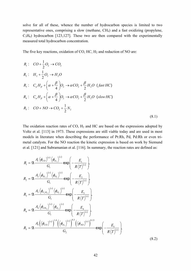
solve for all of these, whence the number of hydrocarbon species is limited to two representative ones, comprising a slow (methane, CH4) and a fast oxidizing (propylene, C3H6) hydrocarbon [123,127]. These two are then compared with the experimentally measured total hydrocarbon concentration. The five key reactions, oxidation of CO, HC, H2 and reduction of NO are:
1 2 2
2 2 2 2
3 2 2 2
4 2 2 2
5 2 2
1 21 2
4 2
4 2
1 2
:
:
: ( )
: ( )
:
R CO O CO
R H O H O
R C H O CO H O fast HC
R C H O CO H O slow HC
R CO NO CO N
α β
α β
β βα α
β βα α
+ →
+ →
⎛ ⎞+ + → +⎜ ⎟⎝ ⎠⎛ ⎞+ + → +⎜ ⎟⎝ ⎠
+ → +
(8.1) The oxidation reaction rates of CO, H2 and HC are based on the expressions adopted by Voltz et al. [113] in 1973. These expressions are still viable today and are used in most models in literature when describing the performance of Pt:Rh, Pd, Pd:Rh or even tri-metal catalysts. For the NO reaction the kinetic expression is based on work by Siemund et al. [121] and Subramanian et al. [116]. In summary, the reaction rates are defined as:
( ) ( ) ( )
2
2 2
3 6 2
4 2
2
1 11
1
2 22
1
3 33
1
4 44
1
0 31 4 0 13
5
52
( )( )
( )
( ) ( )
( )
( ) ( )
( )
( ) ( )
( )
.. .( )( ) ( )
exp ,
exp ,
exp ,
exp ,
e
ssCO O
s
s s
H O
s
s s
C H O
s
s s
CH O
s
ss sCO O NO
A ER
G R T
A ER
G R T
A ER
G R T
A ER
G R T
AR
G
φ φ
φ φ
φ φ
φ φ
φ φ φ
⎛ ⎞⎜ ⎟= −⎜ ⎟⎝ ⎠
⎛ ⎞⎜ ⎟= −⎜ ⎟⎝ ⎠
⎛ ⎞⎜ ⎟= −⎜ ⎟⎝ ⎠
⎛ ⎞⎜ ⎟= −⎜ ⎟⎝ ⎠
=
A
A
A
A
A 5( )xp ,s
E
R T
⎛ ⎞⎜ ⎟−⎜ ⎟⎝ ⎠
(8.2)
43
where G1 and G2 are inhibition terms defined as,
( )( ) ( ) ( )
( ) ( )
3 6
3 6
2
1 1 2
22 0 7
3 4
0 17 2
2 5
1
1 1
( )( ) ( )
.( )( ) ( )
.( ) ( ) ( )
,
,
ss sCO C H
ss sCO C H NO
s s sCO
G T K K
K K
G T T K
φ φ
φ φ φ
φ−
= + + ×
⎛ ⎞⎛ ⎞+ +⎜ ⎟⎜ ⎟⎝ ⎠⎝ ⎠
= +
(8.3) The rate equation of the reaction of O2 is calculated by balancing oxygen concentrations in the above reactions. Thus,
( )1 26 3 42 2 4
R RR R Rβα⎛ ⎞= + + + +⎜ ⎟
⎝ ⎠ (8.4)
The cross sectional distributions of the flow velocity, temperature and concentration profiles in the exhaust have been assumed to be uniform. The ‘film model’ was adopted for the washcoat and the reactions occurring on its surface. This model approximates the washcoat with a solid-gas interface where the reactions take place. All diffusion within the washcoat is neglected, i.e. it is assumed that all active sites are available to gaseous-phase species at the washocat interface only. Concentration gradients within the washcoat and subsequent reactions ‘only’ become significant at higher temperature, in excess of 430 °C [119], and can therefore be neglected when studying the lab-scale regeneration. 8.2 Governing equations The conservation of species and energy is given below for the gas and solid phase, respectively. Gas phase: In order to write the mass balance for the exhaust gas through the monolith, a mean bulk
value, giφ ( ) , is employed for the gas-phase fraction of each species:
( ) 1 6
( ) ( )( ) ( )
( )( ) ( ) ( ) ( ) ( ) , ,..,
g gg gi i
gg g g s gi
i i i
c c ut x
c D c k S ix x
φ φγ
φγ φ φ
∂ ∂+
∂ ∂⎛ ⎞∂∂ ⎜ ⎟= + − =⎜ ⎟∂ ∂⎝ ⎠
(8.5)
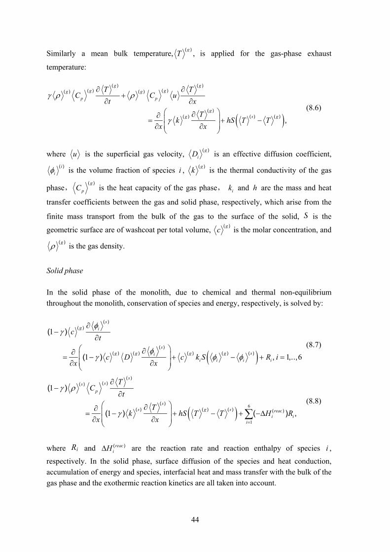
44
Similarly a mean bulk temperature, gT ( ) , is applied for the gas-phase exhaust
temperature:
( )
( ) ( )( ) ( )( ) ( )
( )( ) ( ) ( ) ,
g gg gg g
p p
gg s g
T TC C u
t x
Tk hS T T
x x
γ ρ ρ
γ
∂ ∂+
∂ ∂⎛ ⎞∂∂ ⎜ ⎟= + −⎜ ⎟∂ ∂⎝ ⎠
(8.6)
where u is the superficial gas velocity, giD ( ) is an effective diffusion coefficient,
( )iiφ is the volume fraction of species i , ( )gk is the thermal conductivity of the gas
phase, g
pC( )
is the heat capacity of the gas phase, ik and h are the mass and heat
transfer coefficients between the gas and solid phase, respectively, which arise from the
finite mass transport from the bulk of the gas to the surface of the solid, S is the
geometric surface are of washcoat per total volume, gc ( ) is the molar concentration, and ( )gρ is the gas density.
Solid phase In the solid phase of the monolith, due to chemical and thermal non-equilibrium throughout the monolith, conservation of species and energy, respectively, is solved by:
( )
1
1 1 6
( )( )
( )( ) ( ) ( ) ( ) ( )
( )
( ) , ,..,
sg i
sg g g g si
i i i i
ct
c D c k S R ix x
φγ
φγ φ φ
∂−
∂⎛ ⎞∂∂ ⎜ ⎟= − + − + =⎜ ⎟∂ ∂⎝ ⎠
(8.7)
( )6
1
1
1
( )( )( )
( )( ) ( ) ( ) ( )
( )
( ) ( ) ,
sss
p
ss g s reac
i ii
TC
t
Tk hS T T H R
x x
γ ρ
γ=
∂−
∂⎛ ⎞∂∂ ⎜ ⎟= − + − + −∆⎜ ⎟∂ ∂⎝ ⎠
∑ (8.8)
where Ri and ( )reaciH∆ are the reaction rate and reaction enthalpy of species i ,
respectively. In the solid phase, surface diffusion of the species and heat conduction, accumulation of energy and species, interfacial heat and mass transfer with the bulk of the gas phase and the exothermic reaction kinetics are all taken into account.
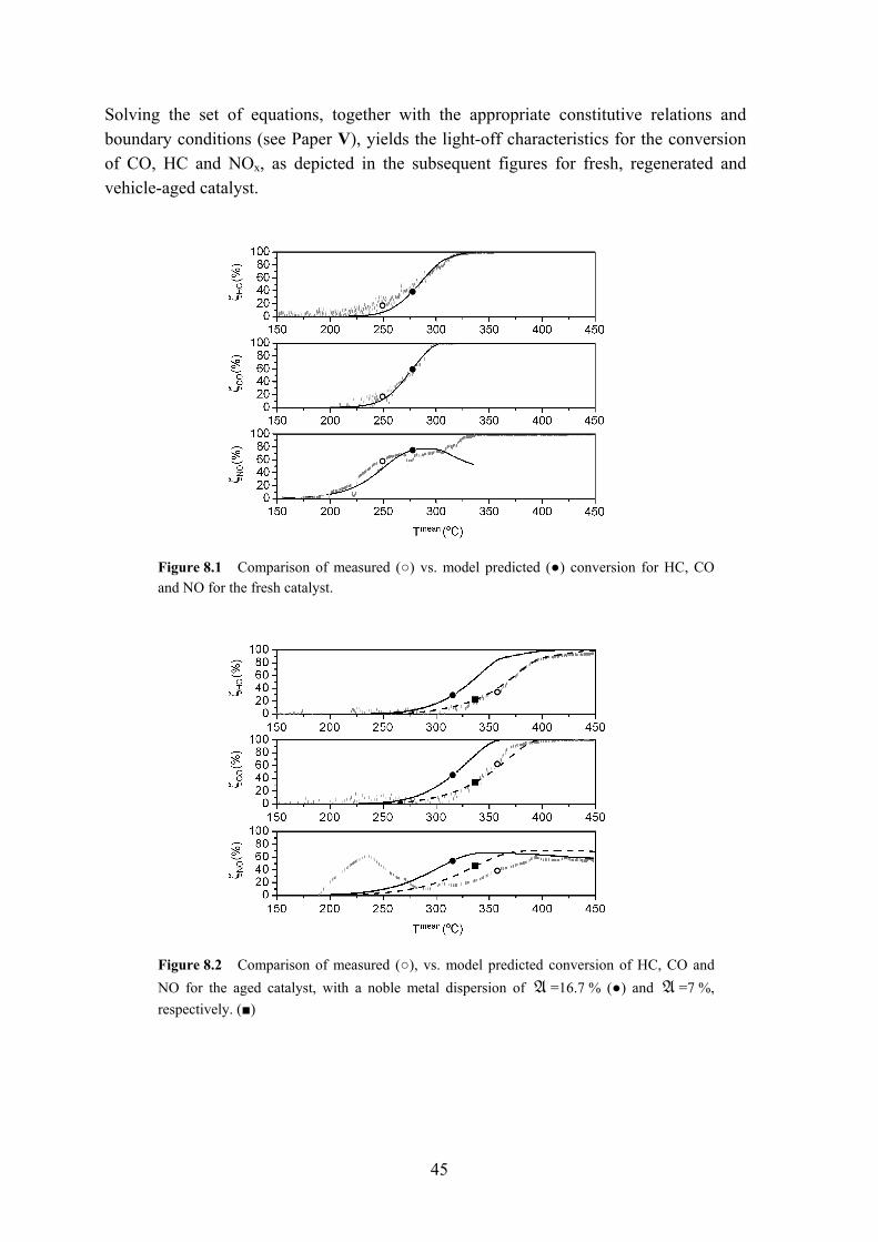
45
Solving the set of equations, together with the appropriate constitutive relations and boundary conditions (see Paper V), yields the light-off characteristics for the conversion of CO, HC and NOx, as depicted in the subsequent figures for fresh, regenerated and vehicle-aged catalyst.
Figure 8.1 Comparison of measured (○) vs. model predicted (●) conversion for HC, CO and NO for the fresh catalyst.
Figure 8.2 Comparison of measured (○), vs. model predicted conversion of HC, CO and NO for the aged catalyst, with a noble metal dispersion of A =16.7 % (●) and A =7 %, respectively. (■)
46
Figure 8.3 Comparison of measured (○) vs. model predicted (●) conversion for HC, CO and NO for the regenerated catalyst.
A good agreement between the model and experimental results was obtained for both the fresh and the regenerated catalysts. This suggests that the reaction mechanism for the fresh catalyst can be employed to describe the behavior of the regenerated catalyst by modifying the dispersion (activity), which was measured experimentally. For the vehicle-aged catalyst, the conversion profiles differ rather significantly from the predicted counterparts. The reason for this is most likely related to several factors: severe loss of active surface due to sintering, with a dispersion (A ) of 17 % to be compared with a dispersion (A ) of 40 % and 90 % for regenerated and fresh, respectively (measured by H2 chemisorption, see Paper II); interaction of species such as P and S on both the activity of the precious metals and the OSC of Ce, is likely to lower the overall efficiency of the active sites available. The magnitude of the influence of these factors on the behavior could be studied numerically by fine tuning the dispersion (or active surface) until the model predictions give better agreement with light-off curves from the experiments. Better agreement was obtained for an active surface noble metal dispersion (A ) of 7 %, more than twice as low as the dispersion measured by chemisorption. In summary, this model allows for the study of properties such as ‘active’ noble metal surface, area, dispersion, particle size effects and interactions of metals (e.g. synergistic effects between Pd-Ce) on the catalyst activity of fresh, aged and regenerated samples.
47
9 Conclusions Several treatments have been proposed and examined with a view to partially or fully regenerating precious metal catalysts in applications such as the three-way catalyst, as well as to ascertain the fundamental mechanisms involved. Such regeneration is necessary, as losses in activity are inevitable due to the chemical and thermal environment of said catalysts. The chemical environment usually occurs due to accumulation of foreign species on the catalyst surface; mainly phosphorous and sulfur compounds originating from the gasoline or additives in the lubrication oils. The thermal environment is known to cause a decrease in active surface area, due to agglomeration of noble metals and loss of the supporting area. The regeneration procedures were carried out and evaluated on a wide array of commercial three-way catalysts, which had been aged under real driving conditions, including both urban and extra-urban (highway) conditions. The first preliminary regeneration methods involved thermal treatments in either oxygen or hydrogen-rich atmospheres, at temperatures ranging from 300 to 700 °C. Changes in activity, primarily measured by the light-off activity, i.e. the temperature at which 50 % conversion is achieved (T50), were found negligible. In fact, a recovery in activity was only detected on heavily sintered catalysts with a high noble metal loading after thermal treatments in an oxygen-rich environment (> 3 hours in air at 500 °C), where the T50 for the CO and HC oxidation reactions was lowered by approximately 20 °C. Based on the findings in the first set of experiments and the conclusions that were drawn, it was hypothesized that the addition of a compound such as chlorine, which creates a mobile metal intermediate, e.g. MOxCly, would enhance the redispersion mechanism. The principal findings and conclusions from the regeneration experiments with chlorine are:
48
• Chlorine (<1 vol.%) in oxygen (300-500 °C, treatment time < 1 hour): A
procedure, which enables the redispersion of metals on a wide variety of catalysts, ‘independent’ of properties such as degree of sintering, noble metal loading or noble metal type. Possible losses of noble metals from the catalyst must be taken into consideration.
• Hydrochloric acid pre-treatment, followed by a thermal regeneration in oxygen (300 - 500 °C, treatment time < 1 hour); Hydrochloric acid solutions can be used instead of gases. Dilute liquids should be used to better control the amount of chlorine interacting with the catalyst surface.
Both ‘small-scale’ and ‘full-scale’ activity measurements and characterization of the catalyst surface structure laid the basis for the catalytic performance evaluation. The scale-up experiments were found to be more demanding in terms of evaluation of catalyst restructuring after regeneration, especially so on relatively fresh catalysts, with effects such as catalyst composition and catalyst-(relative to)-car engine playing a more significant role in the catalyst performance during the full-scale activity tests. The best regeneration results from the light-off ‘small-scale’ experiments obtained on a Pd-Rh based catalyst (metal loading 6000 mg/dm3) aged under extra-urban conditions (catalyst temperatures above 1000 °C are common) were: a lowering of the T50 of approximately 50 °C, 60 °C and 20 °C for CO, HC and NOx, respectively, as compared to the untreated reference. A significant increase in the noble metal dispersion ( )A was
obtained, 17 % for the aged catalyst vs. 40 % after regeneration, with the fresh catalyst possessing a dispersion ( )A of 90 % (Papers I, II)
A purely wet-chemical treatment, especially so in dilute oxalic acid (0.1 M at 50 °C for 1 hour), efficiently removes most of the P and S compounds (approximately 80 %) from the surface, thereby restoring both the OSC and part of the active sites by removing contaminants blocking or poisoning. The OSC of ceria could be restored by up to 50 % after regeneration (Paper III). For the ‘full-scale’ activity evaluation (Paper IV) a high mileage catalyst responded to regeneration (0.6 vol.% Cl2 in air at 500 °C), by a reduction of emissions by 45 %, 32 % and 35 % for CO, HC and NOx, respectively, over the 1200s long EC2000 test. Finally, a mathematical model was derived that adequately describes the catalyst performance and the properties of the active sites for both fresh and regenerated samples (Paper V). The model allows for the analysis of reaction kinetics occurring locally as well as globally in the monolith converter, and suggests that similarities of the Pd–Rh active
49
sites for fresh and regenerated catalysts exist. Furthermore, model predictions indicate that the redispersed Pd and Rh sites after a successful oxy-chlorine treatment interact with washcoat base metals in a similar manner as in the fresh catalyst. The effects of poisons and contaminants (e.g. S, P) on the activity of the Pd-Rh and Ce are significant for the aged catalyst; even though the noble metal dispersion ( )A was estimated to approximately
17 % by H2 chemisorption, the required activity in the mathematical model had to be reduced further to a dispersion ( )A of 7 % in order to predict light-off characteristics
similar to the experimentally determined counterparts. This can be explained by the fact that the reaction kinetics does not take fouling on the washcoat into account, which is significant for the aged catalyst prior to regeneration. Of the proposed methods, three emerge as viable and promising techniques to partially recover lost catalytic activity:
• Thermal gas treatment in a controlled gas atmosphere: this treatment aims to restore the active sites (e.g. noble metals), by redispersing and breaking agglomerated, larger metal crystallites (>50 nm) into smaller particles.
• Wet-chemical treatment with a dilute acid; the wet-chemical treatment seeks to remove accumulated contaminants, primarily through dissolution and thereby extraction from the catalyst.
• Thermal treatment in combination with a dilute acid treatment: this technique combines the two aforementioned individual treatments.
An important feature of the proposed regeneration treatments is that these can be applied in-situ, i.e. without dismantling the on-board catalyst, as opposed to the present treatment of spent TWC catalysts, which involves the extraction of noble metals. As such, the discussed treatments constitute novel and simple alternatives for efficient regeneration of spent automotive catalysts.

50

51
Acknowledgments First, I want to thank Professor Sven Järås for giving me the opportunity to carry out a PhD at the department. I also thank my supervisor, Associate Professor Magali Boutonnet, for her supervision. I would like to thank the colleagues (former and present) at Chemical Technology and Chemical Reaction Engineering, who enlivened and created a stimulating atmosphere. Special thanks to my room mates Ulf Nylén and Johan Agrell for the relaxing discussions and their friendship. Even though I will most likely never learn French, the spiritual guidance from Benny and Michel was much appreciated. I would also like to thank Fredrik Klingstedt and Professor Dmitry Yu. Murzin for their support and help during my stay at the Åbo Akademi University. I would also like to thank Lars Eriksson for his help and valuable input during my stay at AVL-MTC. I am very grateful to Christina Hörnell for improving the linguistic quality of this thesis and to Inga Groth for her assistance with the analytical instruments. The European Union provided financial support within the Regencats programme under project no. G5RD-CT-2000-00376. I would also like to express my gratitude to my brother Erik for his never-ending support. Finally, I dedicate this thesis to my parents, without whom I would not be where I am today.

52
53
References 1. A. Schafer, Transp. Res. A 6 (1998) 455. 2. H.L. MacLean, L.B. Lave, Prog. Energy Combust. Sci. 29 (2003) 1. 3. US Environmental Protection Agency, www.epa.gov, accessed 2006-04-03. 4. J.B. Heywood, Internal combustion engine fundamentals, McGraw-Hill book
company, Singapore, 1988. 5. J. Zeldovich, Acta Physiochimica URSS, 21 (1946) 577. 6. G.A. Lavoie, J.B. Heywood, J.C. Keck, Comb. Sci. Tech. 1 (1970) 313-326. 7. N.J.L. Gense, R.J. Vermeulen (2002), N2O formation in vehicle catalysts, TNO
report 02.OR.VM.017.1/NG (28 February 2002) 8. Directive 98/69/EC. Emission standards: European Union. Cars and light trucks.
http://www.dieselnet.com/standards/eu/ld.html, accessed 2006-04-03. 9. D.S. Lafyatis, G.P. Ansell, S.C. Bennett, J.C. Frost, P.J. Millington,
R.R. Rajaram, A.P. Walker, T.H. Ballinger, Appl. Catal. B 18 (1998) 123. 10. R.J. Farrauto, R.M. Heck, Catal. Today 51 (1999) 351. 11. M. Shelef, R.W. McCabe, Catal. Today 62 (2000) 35. 12. G.C. Koltsakis, A.M. Stamatelos, Prog. Energy Combust. Sci. 23 (1997) 1. 13. R.M. Heck, R.J. Farrauto, Appl. Catal. A 221 (2001) 443. 14. T.E. Hoost, K. Otto, Appl. Catal. A 91 (1992) 39. 15. T. Kobayashi, T. Yamada, K. Kayano, Appl. Catal. B 30 (2001) 287. 16. M.H. Yao, R.J. Baird, F.W. Kunz, T.E. Hoost, J. Catal. 166 (1997) 67. 17. H.W. Jen, G.W. Graham, W. Chun, R.W. McCabe, J.P. Cuif,
S.E. Deutsch, O. Touret, Catal. Today 50 (1999) 309. 18. H. Vidal, J. Kašpar, M. Pijolat, G. Colon, S. Bernal, A. Cordón,
V. Perrichon, F. Fally, Appl. Catal. B 27 (2000) 49. 19. H. Vidal, J. Kašpar, M. Pijolat, G. Colon, S. Bernal, A. Cordón,
V. Perrichon, F. Fally, Appl. Catal. B 30 (2001) 75. 20. D. Duprez, C. Descorme, T. Birchem, E. Rohart, Top. Catal. 16/17 (2001) 49. 21. L.F. Liotta, A. Macaluso, A. Longo, G. Pantaleo, A. Martorana,
G. Deganello, Appl. Catal. A 240 (2003) 295. 22. R.D. Monte, J. Kašpar, Top. Catal. 28 (2004) 47. 23. G.G. Fisher, J.R. Theis, M.V. Casarella, S.T. Mahan, SAE Paper No. 931034, 1993. 24. G.W. Graham, H.W. Jen, R.W. McCabe, A.M. Straccia, L.P. Haack, Catal. Lett. 67
(2000) 99. 25. C. Leitenburg, A. Trovarelli, J. Llorca, F. Cavani, G. Bini, Appl. Catal. A 139
(1996) 161. 26. L- Kepiński, M. Wocyrz, Appl. Catal. A 150 (1997) 197. 27. M. Fernández-Garcίa, A. Martίnez-Arias, L.N. Salamanca, J.M. Coronado, J.A.
Anderson, J.C. Conesa, J. Soria, J. Catal. 187 (1999) 474. 28. P. Bera, K.C. Patil, V. Jayaram, G.N. Subbanna, M.S. Hegde, J. Catal. 196
(2000) 293.
54
29. J. Barbier, D. Duprez, Appl. Catal. B 4 (1994) 105. 30. P. Fornasiero, G. Balducci, R. Di Monte, J. Kašpar, V. Sergo, G. Gubitosa, A.
Ferrero, M. Graziani, J. Catal. 164 (1996) 173. 31. J.R. González-Velasco, M.A. Gutiérrez-Ortiz, J-L. Marc, J.A. Botas,
M.P. González-Marcos, G. Blanchard, Appl. Catal. B 22 (1999) 167. 32. M.F.M. Zwinkels, S.G. Järås, P.G. Menon, Catal. Rev. Sci. Eng. 35 (3) (1993) 319. 33. J.S. Church, N.W. Cant, D.L. Trimm, Appl. Catal. A 101 (1993) 105. 34. M.F.L. Johnson, J. Catal. 123 (1990) 245. 35. R.A. Dalla Betta, Catal. Today 35 (1997) 129. 36. A. Amberntsson, H. Persson, P. Engström, B. Kasemo, Appl. Catal. B 31 (2001) 27. 37. H. Abdulhamid, E. Fridell, M. Skoglundh, Top. Catal. 30/31 (2004) 161. 38. L. Olsson, E. Fridell, M. Skoglundh, B. Andersson, Catal. Today 73 (2002) 263. 39. Y. Cai, H.G. Stenger, C.E. Lyman, J. Catal. 161 (1996) 123. 40. Y.J. Mergler, B.E. Nieuwenhuys, J. Catal. 161 (1996) 291. 41. Z. Hu, F.M. Allen, C.Z. Wan, R.M. Heck, J.J. Steger, R.E. Lakis,
C.E. Lyman, J. Catal. 174 (1998) 13. 42. J.R. González-Velasco, J.A. Botas, R. Ferret, M.P. González-Marcos,
J-L. Marc, M.A. Gutiérrez-Ortiz, Catal. Today 59 (2000) 395. 43. R.K. Herz, E.J. Shinouskis, Ind. Eng. Chem. Prod. Res. Dev. 24 (1985) 385. 44. R.M.J. Fiederow, S.E. Wanke, J. Catal. 43 (1976) 34. 45. A. Martίnez-Arias, M. Fernández-Garcίa, A. Iglesias-Juez, A.B. Hungrίa, J.A.
Anderson, J.C. Conesa, J. Soria, Appl. Catal. B (1992) 151. 46. T.N. Angelidis, S.A. Sklavounos, Appl. Catal. A 133 (1995) 121. 47. D.D. Beck, J.W. Sommers, C.L. DiMaggio, Appl. Catal. B 11 (1997) 257. 48. C.E. Hori, H. Permana, K.Y. Simon, A. Brenner, K. More, K.M. Rahmoeller, D.
Belton, Appl. Catal. B 16 (1998) 105. 49. C. Battistoni, V. Cantelli, M. Debenedetti, S. Kačiulis, G. Mattogno,
A. Napoli, Appl. Surf. Sci. 144 (1999) 390. 50. P. Forzatti, L. Lietti, Catal. Today 52 (1999) 165. 51. C.H. Bartholomew, Appl. Catal. A 212 (2001) 17. 52. T. Luo, J.M. Vohs, R.J. Gorte, J. Catal. 210 (2002) 397. 53. V. Kröger, M. Hietikko, U. Lassi, J. Ahola, K. Kallinen, R. Laitinen,
R.L. Keiski, Top. Catal. 31 (2004) 469. 54. D.D. Beck, J.W. Sommers, C.L. DiMaggio, Appl. Catal. B 11 (1997) 273. 55. D.E. Angove, N.W. Cant, Catal. Today 63 (2000) 371. 56. D.R. Liu, J.S. Park, Appl. Catal. B 2 (1993) 49. 57. M. Lovei, World Bank Tech. Paper No. 397 (1997). 58. D.D. Beck, J.W. Sommers, Appl. Catal. B 6 (1995) 185. 59. D.L. Mowery, R.L. McCormick, Appl. Catal. B 34 (2001) 287. 60. J.K. Lampert, M.S. Kazi, R.J. Farrauto, Appl. Catal. B 14 (1997) 211. 61. T.C. Yu, H. Shaw, Appl. Catal. B 18 (1998) 105.
55
62. S. Johansson, K. Wong, V.P. Zhdanov, B. Kasemo, J. Vac. Sci. Technol. A 17 (1999) 297.
63. M. Shelef, K. Otto, N.C. Otto, Adv. Catal. 27 (1978) 311. 64. M.J. Rokosz, A.E. Chen, C.K. Lowe-Ma, A.V. Kucherov, D. Benson,
M.C. Paputa Peck, R.W. McCabe, Appl. Catal. B 33 (2001) 205. 65. L.L. Hegedus, K. Baron, J. Catal. 54 (1978) 115. 66. C. Larese, F. Cabello Galisteo, M. López Granados, R. Mariscal, J.L.G. Fierro,
M. Furió, R.Fernández Ruiz, Appl. Catal. B 40 (2003) 305. 67. C. Larese, F.Cabello Galisteo, M. López Granados, R. Mariscal, J.L.G. Ferro,
P.S. Lambrou, A.M. Efstathiou, Appl. Catal. B 48 (2004) 113. 68. C. Larese, M. López Granados, R. Mariscal, J.L.G. Fierro, P.S. Lambrou,
A.M. Efstathiou, Appl. Catal. B 59 (2005) 13. 69. T.N. Angelidis, V.G. Papadakis, Appl. Catal. B 12 (1997) 193. 70. F.C. Galisteo, R. Mariscal, M.L. Granados, J.L.G. Fierro, P. Brettes, O. Salas,
Environ. Sci. Technol. 39 (2005) 3844. 71. S.E. Wanke, P.C. Flynn, Catal. Rev. 12 (1975) 93. 72. D.E. Angove, N.W. Cant, D.H. French, K. Kinealy, Appl. Catal. A 194 (2000) 27. 73. U. Lassi, R. Polvinen, S. Suhonen, K. Kallinen, A. Savimäki, M. Härkönen,
M. Valden, R.L. Keiski, Appl. Catal. A 263 (2004) 241. 74. J.A. Moulijn, A.E. Diepen, F. Kapteijn, Appl. Catal. A 212 (2001) 3. 75. I. Sushuma, E. Ruckenstein, J. Catal. 108 (1987) 77. 76. J.T. Richardson, Principles of catalyst development, Plenum Press, New York,
1989. 77. S.J. Schmieg, D.N. Belton, Appl. Catal. B 6 (1995) 127. 78. E. Rogemond, R. Fréty, V. Perrichon, M. Primet, M. Chevrier, C. Gauthier,
F. Mathis, Appl. Catal. A 156 (1997) 253. 79. A. Martίnez-Arias, M. Fernández-Garcίa, A. Iglesias-Juez, A.B. Hungrίa,
J.A. Anderson, J.C. Conesa, J. Soria, Appl. Catal. 31 (2001) 51. 80. A. Martίnez-Arias, M. Fernández-Garcίa, A. Iglesias-Juez, A.B. Hungrίa,
J.A. Anderson, J.C. Conesa, J. Soria, Appl. Catal. B 38 (2002) 151. 81. M. Ozawa, M. Kimura, J. Mat. Sci. Lett. 9 (1990) 291. 82. P.O. Thevenin, A.G. Ersson, H.M.J. Kušar, P.G. Menon, S.G. Järås, Appl. Catal. A
212 (2001) 189. 83. G.W. Graham, H.-W. Jen, W. Chun, R.W. McCabe, Catal. Lett. 44 (1997) 185. 84. G.W. Graham, H.-W. Jen, W. Chun, R.W. McCabe, J. Catal. 182 (1999) 228. 85. H. Shinjoh, H. Muraki, Y. Fujitani, Stud. Surf. Sci. Catal. 71 (1991) 617. 86. J.G. McCarthy, Catal. Today 26 (1995) 283. 87. G. Groppi, C. Cristiani, L. Lietti, P. Forzatti, in: A. Corma, F.V. Melo,
S. Mendioroz, J.L.G. Fierro (Eds.), Studies in surface science and catalysis 130, Elsevier Science, Amsterdam, 2000, p. 3801.
56
88. G. Groppi, G. Artioli, C. Cristiani, L. Lietti, P. Forzatti, in: E. Iglesia, J.J. Spivey, T.H. Fleisch (Eds.), Studies in surface science and catalysis 136, Elsevier Science, Amsterdam, 2001, p. 345.
89. R.J. Farrauto, M.C. Hobson, T. Kennelly, E.M. Waterman, Appl. Catal. A 81 (1992) 227.
90. H. Arai, M. Machida, Appl. Catal. A 138 (1996) 161. 91. J.E. Stulga, P. Wynblatt, J.K. Tien, J. Catal. 62 (1980) 59. 92. T.J. Lee, Y.G. Kim, J. Catal. 90 (1984) 279. 93. R.M.J. Fiedorow, S.E. Wanke, Appl. Catal. B 14 (1997) 249. 94. D.D. Beck, C.J. Carr, J. Catal. 144 (1993) 296. 95. H. Lieske, G. Lietz, H. Spindler, J. Völter, J. Catal. 81 (1983) 8. 96. G. Lietz, H. Lieske, H. Spindler, W. Hanke, J. Völter, J. Catal. 81 (1983) 17. 97. K. Foger, H. Jaeger, J. Catal. 92 (1985) 64. 98. C. Contescu, D. Macovei, C. Craiu, C. Teodorescu, J.A. Schwartz, Langmuir 11
(1995) 2031. 99. Z.C. Zhang, B.C. Beard, Appl. Catal. A 188 (1999) 229. 100. J.J. Berzelius, Årsberättelsen om framsteg i fysik och kemi, Royal Swedish Academy
of Sciences, 1835. 101. A. Camia, Catal. Lett. 67 (2000) 1. 102. J.L. Benson, H.S. Hwang, M. Boudart, J. Catal. 30 (1973) 146. 103. R. Di Monte, P. Fomasiero, J. Kašpar, P. Rumori, G. Gubitosa, M. Graziani, Appl.
Catal. B 24 (2000) 157. 104. S. Bernal, J.J. Calvino, G.A. Cifredo, J.M. Gatica, J.A. Omil Perez, J.M. Pintado,
J. Chem. Soc. Faraday. Trans. 89 (1993) 3499. 105. P. Fornasiero, R. Di Monte, G. Ranga Rao, J. Kašpar, S. Meriani, A. Trovarelli,
M. Graziani, J. Catal. 151 (1995) 168. 106. K. Foger, D. Hay, H. Jaeger, J. Catal. 96 (1985) 154. 107. G. Tonetto, M.L. Ferreira, D.E. Damiani, J. Mol. Catal. A 171 (2001) 123. 108. R.A. Daley, S.Y. Christou, A.M. Efstathiou, J.A. Anderson, Appl. Catal. B 60
(2005) 117. 109. H. Birgersson, M. Boutonnet, S. Järåsm L. Eriksson, Top. Catal. 30 (2004) 433. 110. P.O. Thevenin, A. Alcalde, L.J. Petterson, S.G. Järås, J.L.G. Fierro, J. Catal. 215
(2003) 78. 111. F. Klingstedt, H. Karhu, A.K. Neyestanaki, L.-E.Lindfors, T. Salmi, J. Väyrynen,
J. Catal. 206 (2002) 248. 112. H.C. Yao, Y.F. Yu Yao, J. Catal. 86 (1984) 254. 113. S.E. Voltz, C.R. Morgan, D. Liederman, S.M. Jacob, Ind. Eng. Chem. Prod. Res.
Dev. 12 (1973) 294. 114. S.H. Oh, J.C. Cavendish, Ind. Eng. Prod. Res. Dev. 21 (1982) 29. 115. S.H. Oh, J.C. Cavendish, Ind. Eng. Prod. Res. Dev. 22 (1983) 509. 116. B. Subramanian, A. Varma, Ind. Eng. Chem. Prod. Res. Dev. 24 (1985) 512. 117. K. Zygourakis, Chem. Eng. Sci. 44 (1989) 2075.
57
118. U. Ullah, S.P. Waldram, C.J. Bennett, T. Truex, Chem. Eng. Sci. 47 (1992) 2413. 119. R.E. Hayes, S.T. Kolaczkowski, Chem. Eng. Sci. 49 (1994) 3587. 120. G.Groppi, A. Belloli, E. Tronconi, P. Forzatti, Chem. Eng. Sci. 50 (1995) 2705. 121. S. Siemund, J.P. Leclerc, D. Schweich, M. Prigent, F. Castagna, Chem. Eng. Sci. 51
(1996) 3709. 122. G.C. Koltsakis, P.A. Konstandinidis, A.M. Stamatelos, Appl. Catal. B 12 (1997)
161. 123. C. Dubien, D. Schweich, G. Mabilon, B. Martin, M. Prigent, Chem. Eng. Sci. 3
(1998) 471. 124. S.H. Chan, D.L. Hoang, Int. J. Heat Mass Transfer 42 (1999) 4165. 125. G.C. Koltsakis, A.M. Stamatelos, Chem. Eng. Sci. 54 (1999) 4567. 126. D.N. Tsinglou, G.C. Koltsakis, D.K. Missirlis, K.J. Yakinthos, Appl. Math.
Modelling 28 (2004) 775. 127. J.C: Kuo, C.R. Morgan, H.G. Lassen, SAE Paper No. 710289, 1971.