Embed Size (px)
Citation preview
Pennsylvania State University University of Maryland University of Virginia
Virginia Polytechnic Institute and State University West Virginia University
The Pennsylvania State University The Thomas D. Larson Pennsylvania Transportation Institute
Transportation Research Building University Park, Pennsylvania 16802-4710 Phone: 814-863-1909 Fax: 814-863-3707
www.pti.psu.edu/mautc
DEVELOPING A TELE-ROBOTIC PLATFORM
FOR BRIDGE INSPECTION
i
FINAL REPORT
DEVELOPING A TELE-ROBOTIC PLATFORM FOR BRIDGE INSPECTION
Steven Chase
Research Professor
Matthew Edwards Graduate Research Assistant
Center for Transportation Studies
University of Virginia
May 2011
Prepared for
Virginia Transportation Research Council
And Mid-Atlantic University Transportation Centers Program
DISCLAIMER
The contents of this report reflect the views of the authors, who are responsible for the facts and the accuracy of the data presented herein. The contents do not necessarily reflect the official views or policies of the Virginia Department of Transportation, the Commonwealth Transportation Board, or the Federal Highway Administration. This report does not constitute a standard, specification, or regulation.
1. Report No. UVA-2009-02
2. Government Accession No. 3. Recipient’s Catalog No.
4. Title and Subtitle DEVELOPING A TELE-ROBOTIC PLATFORM FOR BRIDGE INSPECTION
5. Report Date May 2011
6. Performing Organization Code
7. Author(s) Steven Chase, P.E. and Matthew Edwards 8. Performing Organization Report No.
9. Performing Organization Name and Address University of Virginia Center for Transportation Studies 351 McCormick Road, Charlottesville, VA 22904
10. Work Unit No. (TRAIS)
11. Contract or Grant No. DTRT07-G-0003
12. Sponsoring Agency Name and AddressVirginia Department of Transportation 530 Edgemont Road, Charlottesville, VA 22903 US Department of Transportation Research & Innovative Technology Admin UTC Program, RDT-30 1200 New Jersey Ave., SE Washington, DC 20590
13. Type of Report and Period Covered Final June 2009 to May 2011
14. Sponsoring Agency Code
15. Supplementary Notes COTR: Chris Metka, 717-787-8065, [email protected]
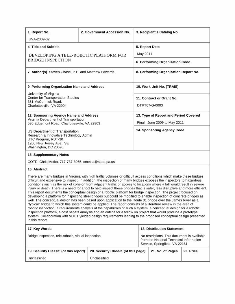
16. Abstract There are many bridges in Virginia with high traffic volumes or difficult access conditions which make these bridges difficult and expensive to inspect. In addition, the inspection of many bridges exposes the inspectors to hazardous conditions such as the risk of collision from adjacent traffic or access to locations where a fall would result in severe injury or death. There is a need for a tool to help inspect these bridges that is safer, less disruptive and more efficient. This report documents the conceptual design of a robotic platform for bridge inspection. The project focused on developing a platform for inspecting steel bridges but could be modified to enable inspection of concrete bridges as well. The conceptual design has been based upon application to the Route 81 bridge over the James River as a "typical" bridge to which this system could be applied. The report consists of a literature review in the area of robotic inspection, a requirements analysis of the capabilities of such a system, a conceptual design for a robotic inspection platform, a cost benefit analysis and an outline for a follow on project that would produce a prototype system. Collaboration with VDOT yielded design requirements leading to the proposed conceptual design presented in this report.
17. Key Words Bridge inspection, tele-robotic, visual inspection
18. Distribution Statement No restrictions. This document is available from the National Technical Information Service, Springfield, VA 22161
19. Security Classif. (of this report) Unclassified
20. Security Classif. (of this page) Unclassified
21. No. of Pages
22. Price
ii
ABSTRACT
There are many bridges in Virginia with high traffic volumes or difficult access conditions which make these bridges difficult and expensive to inspect. In addition, the inspection of many bridges exposes the inspectors to hazardous conditions such as the risk of collision from adjacent traffic or access to locations where a fall would result in severe injury or death. There is a need for a tool to help inspect these bridges that is safer, less disruptive and more efficient. This report documents the conceptual design of a robotic platform for bridge inspection. The project focused on developing a platform for inspecting steel bridges but could be modified to enable inspection of concrete bridges as well. The conceptual design has been based upon application to the Route 81 bridge over the James River as a "typical" bridge to which this system could be applied. The report consists of a literature review in the area of robotic inspection, a requirements analysis of the capabilities of such a system, a conceptual design for a robotic inspection platform, a cost benefit analysis and an outline for a follow on project that would produce a prototype system. Collaboration with VDOT yielded design requirements leading to the proposed conceptual design presented in this report.

iii
1
FINAL REPORT
DEVELOPING A TELE-ROBOTIC PLATFORM FOR BRIDGE INSPECTION
Steven Chase, P.E. Research Professor
Matthew Edwards
Graduate Research Assistant
INTRODUCTION
The main reasons for considering this robotic inspection technology are to improve the safety and efficiency of the bridge inspection process. This paper identifies various inspection technologies being used in other industries. The capabilities of these systems are discussed as well as the key components and concepts. The intent is to document that robotic inspection technology is a viable approach to bridge inspection and that much of the subsystems that would be required to implement such a capability already exist and are readily available. Consequently, this project would be much more the integration of existing technologies than the development of totally new technologies. The technical risk is therefore minimal and manageable and more than offset by the potential benefits that such a system would offer. By far, the most common approach to bridge inspection in Virginia, and the rest of the world, is visual inspection by trained and experienced inspectors. To perform these inspections, these individuals must have visual access to the bridge and its components. This becomes difficult and time consuming when the bridge is extremely long or spans over an area where the underside cannot be easily seen. It can also require the inspector to reach locations that are hazardous. Many bridges are high and span dangerous rivers, valleys, roadways, railroads and other features. Visual inspection requires the inspector to look at all of the locations where a problem is likely to occur. To reach these locations special inspection trucks and under bridge access equipment is used. These are often placed on the bridge and enable the inspector to access the underside of the bridge. These trucks, and associated work zones, can lead to delay or even a stoppage of traffic across the bridge resulting in congestion in many areas. Consequently, there is reluctance to employ this method on bridges which experience a large amount of traffic on a regular basis. This access equipment is very expensive and only a few of these trucks are available throughout Virginia and the trucks that are available are constantly being used. This high demand can lead to bridges being inspected infrequently due to scheduling issues. Developing a robotic inspection platform, as conceptualized in this report, would address these limitations by enabling inspections of bridges from the underneath, without the need to disrupt traffic and also reduce the risks to the inspectors. The expected capabilities of this system have many advantages over current methods.
2
There have also been many recent developments in structural health monitoring and bridge evaluation that are based upon placing sensors on bridges. It is expected that this robotic system will not only be able to inspect bridges, it will also have the capability ability to place sensors on a bridge and would therefore help enable the use of the best available solutions for bridge health monitoring and diagnosis. This is particularly advantageous because the robotic system will be able to place sensors in hard to reach places without exposure to hazardous locations or stopping traffic. Very often, sensor placement is dictated more by access limitations than placement at optimal locations. A robotic platform would allow the inspector to place sensors where they need to go rather than where they can reach. The conceptual designed was driven by requirements that were considered essential by VDOT as well as those that were considered desirable. These requirements address factors such as cost, complexity, range, and type of information needed. This report documents a conceptual design of a robotic inspection platform and presents a proposed work plan so that this work can be conducted in the near future. Because the cost and the time it would take to develop a bridge inspection platform prototype could be significant, it was considered more sensible to review the literature and current practices related to inspection robots being used in other industries and then bring together already developed concepts and elements from various methods in order to formulate a conceptual prototype. The next section briefly summarizes the literature review which was conducted in this research.
Literature Review
The literature review looked at other industries which are currently using robotic inspection and reviewing current inspection practices. Storage Tanks External Corrosion Detection A number of research projects have been conducted in the area of developing a robot for the inspection of above-ground storage tanks. Researchers have experimented with different locomotion and adhesion mechanisms. A major challenge is that the walls are not designed for robots to move across. These storage tanks are built by welding rectangular sections of steel plates together which creates seams around three centimeters is length at the joints. There are also often staircases on the exterior of the tanks which provide additional challenges for a robot to traverse. Due to the difficulty which arises due to these obstacles, locomotion techniques such as walking have dominated researcher's attention. There have been a number of walking type locomotion robots which have been developed but the design and control complexities involved make them very impractical in most applications. Crawling type locomotion, which is faster and less complex, is commonly used in applications such as inspection and maintenance of above-ground storage tanks.
3
The main task of an above-ground storage tank inspection robot is to protect the tanks from unexpected leaks which could occur due to corrosion and pitting in the tank walls. Routine checkups require a lot of time and capital which further emphasizes the need for automation. Love P. Kalra and Jason Gu have developed an autonomous crawling type wall climbing robot which uses permanent magnets as an adhesion mechanism to climb the walls and perform all of the inspection operations independently. The robot consists of a box shape aluminum frame, drive train, motors, and tracked wheels complete with permanent magnets. The tank is mainly inspected to sense internal flaws. This can be done through ultrasonic or eddy-current sensors. These methods allow the detection of internal flaws without destroying the material which is being tested. The main challenge with developing a climbing robot for above-ground storage tank inspection is coverage. Researchers such as Love P. Kalra and Jason Gu have developed coverage algorithms which attempt to address this problem. Their algorithm divides the space into a uniform grid with each cell the size of the sensor (Kalra, 2007). Their robot has been tested and is successful in inspecting of above-ground storage tanks. Internal Corrosion Detection There is also much research in the area of robotic above ground storage tank inspection from the inside of the tank. Current inspection techniques involves emptying the tank which is expensive and time consuming. The inspection technique addressed in this section offers a more cost-effective and timely solution to the continual inspection of areas which are hard to reach in above-ground storage tanks. One such robotic system which has been developed in such a way is the Neptune system. This system incorporates various robotic mechanisms and inspection techniques to accurately determine the integrity of the above-ground storage tank without having to empty the tank. The Neptune above-ground storage inspection system involves immersing sensors in the petroleum product and then using video and ultrasonic to ascertain from the inside-out the state of corrosion of the side-walls as well as the floor (Schempf, 1995). This process helps eliminate emptying or cleaning the tank as well as not requiring humans to walk through the tank and inspect it manually. The Neptune system has been tested and has been successfully demonstrated to the U.S. Army Corps of Engineers as well as industries interested in using the technology such as Exxon and Mobil. Robotic systems such as the Neptune system are able to inspect tanks from the inside so that the tank walls and floors can be successfully inspected. Above-ground storage tank inspection methods are fairly simple and understanding them can lead to successfully implementing a robot for bridge inspection. Pipelines The reliability and durability of main gas lines are of extreme importance for a successful operation of gas transporting plants. Aging gas lines require constant inspection because the smallest defect could turn into a major problem quickly. The evaluation of these lines is the main problem in this industry. Corrosive damage on the walls of the pipes is the main cause of emergency failure. A pipeline inspection gauge is one way to successfully inspect these gas lines. These PIGs often travel at high speeds and collect various inspection information along their
4
journey inside of the pipeline. The main benefit of using a PIG is that it does not require stopping an operation. The first step in using a pig is placing it into the pig launcher. The launcher is then closed and the pressure inside the pipe is used to push it along until it reaches the receiving trap or pig catcher. These PIGs have been used for many years in cleaning large diameter pipes in the oil industry. Current research involves creating PIGs which are able to inspect small diameter piping so that efficiency can be maximized. PIGs often use technologies such as magnetic flux leakage and ultrasonic detection to inspect piping. Some PIGs even use calipers to measure the geometry of the piping as well.
Ship Hulls Ship hull inspection is an area where robotics offer a considerable advantage in terms of cost and time taken during an inspection. Ship hull inspections are currently conducted at 5, 2.5, 1 year intervals or when needed (Menegaldo, 2009). These inspections are currently executed through one of two methods. The first involves docking the vessel, emptying the tanks, and doing visual inspection and the second involves applying nondestructive testing techniques without discontinuing the ship's operation. Both of these methods have significant downsides which is why there has been much research in the development of a mobile robot for ship hull inspection. There are few systems which are able to inspect both dry and underwater parts. One such design is presented by Caralho et al. where the robot fixates over the hull via four magnetic wheels (Menegaldo, 2009). The robot carries a video camera as well as an eight-channel US system. There are other similar robots worldwide which have served a similar application but they are often too costly and confusing for practical application. Likewise, there currently robotic systems which are capable of solely inspecting the dry part of the ship hull. These robots typically consist of a crawler driven by two magnetic tracks which are specially designed to offer a high coefficient of friction (Menegaldo, 2009). This high coefficient of friction helps the robot operate vertically where there is no thrust force from the water. Ship hull inspection below the water is the current area where most researcher's attention has been given. There is currently a project being developed by Luciano Menegaldo which is capable of performing United States inspections and possible other nondestructive inspection techniques on ship hulls underwater. This project represents the latest in this area of development. The robot uses a pair of magnetic tracks for adhesion to the side of the ship hull. These tracks give the robot the ability to surpass certain obstacles such as barnacles and welds that have a high probability of being encountered. A Labview application installed in the robot allows the operator to view the robot's camera images and combined with precise measurements help successfully learn the status of the ship hull's condition. The robot is powered through a cable connecting itself to the ship's power source. This proposed robot for ship hull inspection has shown successful locomotion and adhesion behavior in laboratory tests but has not yet been used commercially. Cable Inspection Robots
5
Above Ground Power Line Cable Inspection The most popular form of power line inspection involves manual inspection which is slow, hazardous, expensive, and often unreliable (Katranik, 2008). There has also been talked of using an UAV or an unmanned Aerial Vehicle for power line inspection. This would involve a small helicopter autonomously traveling along the power lines and finding and documenting faults. Many organizations have recently completed projects aiming to create a successful climbing robot that is able to inspect power lines. The Chinese Academy of Science, in collaboration with other academic institutions, have been a major player in the development of such technology. One of their most advanced projects involves a dual-arm robot designed to inspect live-lines at extra-high-voltage (Toussaint, 2009). The platform is designed to hang from the transmission line on its two wheeled arms so that it has an optimal view of the conductors below. The inspection process for this robot involves the use of a video camera which is pointed down towards the lines. Hydro-Quebec's research institute has also been a major player in the development of a climbing robot for inspection of transmission lines. They developed the LineScout which is the first and only robot of its kind which has successfully been used in the field to date (Toussaint, 2009). The robot was first presented by Mountambault et al and it involves a two-wheel LineScout platform which is able to cross obstacles by deploying a two-gripper auxiliary frame under the cable and then securing a grasp on both sides of the obstacle (Toussaint, 2009). The crossing sequence only takes two minutes and it can clear objects up to 0.76 meters in diameter. The robot is developed to be controlled via an operator and then shift towards an autonomous mode. LineScout relies heavily on a variety of sensors for safety and control. The successful development of the LineScout shows that the high demand of a climbing robot for inspection of transmission lines is not going unnoticed. Underground Power Line Cable Inspection Underground cable networks are traditionally inspected through the aid of a fixed distributed sensor network or by a specialized technician. These methods involve high cost and low accuracy. Recent advancements in the robotics industry indicate that mobile monitoring could prove to be a viable alternative. Remote monitoring of underground cable systems will also minimize inspection hazards currently faced by human technicians.
Development of a mobile robot platform for underground cable systems has many specific challenges such as space confinement, weight restrictions, size, wireless communication requirements, and adverse environmental conditions (Jiang, 2002). Several mobile monitoring applications focusing on overhead power line inspection have been demonstrated over recent years but not many have addressed underground cables. A robot has currently been developed to traverse cables with a diameter of four to eight centimeters as well as navigate with obstacles in its path. This robot is capable of operating autonomously or by human tele-operation by a LAN or an internet connection. The robot consists of three segments which are coupled by two freely rotating joints. Each segment contains a pair of legs which can hug or release the cable. The middle segment is the location of the robotic platform’s power source. The two end segments are equipped with a sensor array. These sensors include infrared sensors, dielectrometry sensors, and acoustic sensors. The infrared is used to conduct a thermal analysis used to evaluate the insulation status of the cable. The dielectrometry sensors are used to gather information
6
concerning the aging status of the cables by measuring the dielectric properties of insulating materials (Jiang, 2002). Acoustic sensors are preferred due to its non-destructive nature and immunization to electrical interference allowing it to operate on energized cables. The major challenge in the development of a robotic platform for underground power cable inspection is signal processing. A large amount of data is obtained which in turn requires considerable computational resources. This is difficult due to the size constraints of the robotic platform as well as its harsh operating environment. The two main options are local signal processing and remote signal processing. Remote signal processing seems more realistic because the size constraints of the robotic platform make it hard to process all of the data onboard. While the development of robotic platforms for underground power cable inspection is extremely useful for its operation, it does not greatly benefit the development of a robotic platform for bridge inspection.
Cable bridge inspection Many cable-stayed bridges in the United States have shown signs of damage mostly due to their susceptibility to corrosion and wind-induced vibrations. The most important component of cable-stayed bridges are the cables themselves. These cables need to remain in prime condition in order for the bridge to function safely. There are currently many different robots which are used to inspect these cable bridges. A wheel-based cable inspection robot system has been developed which is capable of climbing up and down cables in order to detect deflections on a bridge (Wang 2004). This method has proved superior to the conventional method of visual inspection. This wheel-based climbing robot has been produced through a nondestructive evaluation program for developing better tools to inspect locations on steel bridges. The robot is composed of three equally spaced modules. One of the modules is powered by a DC motor while the other two are passive. The robot has two main components which monitor the integrity of the cable. The first method is visual inspection by a CCD camera and the second method is measuring the magnetic flux leakage based on damage detection. This robot could not be used for the purposes of this paper because it is designed to ascend and descend a cylindrical cable. A robotic platform for bridge inspection would need to be able to deal with obstacles efficiently in order to be of beneficial use. While this cable inspection robot seems helpful for inspection of cable-stayed bridges, a new robot must be developed in order to serve the purposes of this project.
Current Bridge Inspection Methods
Trucks on Bridge Lowering Mechanical Arm Although many industries continually advance the state of their robotics, the robot application technologies for the maintenance and safety diagnosis of bridges has lagged behind. Current techniques usually involve an inspector going to the site and visually inspecting the bridge. This inspector counts the number of cracks and crack measurements among other things. These results are often inaccurate and the inspectors are working in a dangerous environment. Inspectors under the bridge usually simply wear a hard-hat for safety. This absence of a major
7
safety device could cause an industrial disaster during the bridge inspection process. The inspectors often have to use a truck and bucket system so they can inspect hard to reach areas. This system is slow in that the inspector must continually be lowered and retrieved during the inspection process. Safety concerns have helped fuel the development of robotic bridge inspection systems which utilized unmanned robotic technology. The system consists of three main parts. These parts are a specially designed car, a guide-rail, and the robot itself (Oh, 2007). This guide-rail is located at the end of a specially designed multilink age system which is attached to the specially designed car. The robot is located on this guide-rail and is capable of moving long distances so it can successfully inspect the entire area beneath the bridge. The robot is capable of moving up and down by either using a scissor or sliding mechanism. The scissor type allows for a larger workspace but the sliding type has smoother motion. This robotic system has been developed and has proven to be successful. A major item which this inspection system wants to address in the future is giving the system the technology to automatically inspect and scan every point on the bridge. This is currently not attainable in that the system would take entirely too long to perform such a task. Although this system is currently available, it is a lengthy process which involves a special car on the bridge. This special car can potentially cause congestion on the roadway. A bridge inspection crawling robot would eliminate this congestion problem and also minimize the time taken to perform such an inspection. Magnetic-Based NDE of Prestressed and Post-Tensioned Concrete Members The Federal Highway Administration issued a request for proposal for a research study on the "Magnetic-Based System for NDE of Prestressing Steel in Pretensioned and Post-Tensioned Concrete Bridges," in April of 1995 (Ghorbanpoor, 2000). This research was carried out effectively and lead to the successful implementation of a robotic system which is capable of detecting corrosion and fracture of prestressing steel in prestressed and post-tensioned concrete bridge members based on the principle of magnetic flux leakage. The system was designed so that it could be applicable to a wide range of bridge members which each contain differing geometrical configurations. The robotic system was also developed to maximize the efficiency of the inspection process by minimizing its installation time and removal from the bridge itself. This project is very similar to the purpose of this paper in that this project's main aim was to use and extend the available knowledge and capability obtained through past studies and developments in the related area (Ghorbanpoor, 2000). The reliability of the developed system and field-worthiness were the two areas of most importance during the research and development stages. Extensive laboratory and field tests involving prestressed concrete members were conducted in order to make sure the system would accurately perform. Through testing, it was shown that the magnetic-flux leakage technique could detect flaws in prestressing steel that were equivalent to a five to ten percent loss of the cross-section. Previously developed systems had many shortcomings which need to be addressed in order to maximize the efficiency of the robotic system. The main shortcomings involve: excessive equipment weight, low testing speed and inefficient data acquisition, difficulties involving system installation and removal, and using
8
outdated electronics and computing devices. The past study conducted by the Federal Highway Administration took proactive steps to address every one of these shortcomings so that the system developed could operate as efficiently as possible. The robotic system's method of inspection involves measuring magnetic flux leakage. Lightweight magnets were selected to provide the required magnetic field as well as to keep the weight of the system to a minimum. These magnets allow for monitoring of the variations of the field due to loss of cross-sectional area of the steel due to corrosion or fracture. The entire robotic system is contained in a lightweight aluminum structural frame. The frame carries the magnets, electronic components, and the control devices. Conducting a test involves attaching the frame to the test beam and controlling the motion of the frame from a remote notebook computer through wireless communication. This wireless communication makes it possible to scan the length of the girder and record and display the test data. This data reflects the variations in a magnetic field induced in the concrete due to corrosion or fractures of the embedded prestressing steel. The computer then analyzes this recorded data to accurately determine the condition of the steel. The discussed system in this section is extremely useful in developing a tele-robotic platform for bridge inspection.
PURPOSE AND SCOPE
The purpose of this project is to determine the feasibility of designing a robotic platform for bridge inspection. This feasibility study can lead to the successful implementation of a robotic bridge inspection system which can then be applied to many bridges in Virginia which are either difficult to inspect, or are unable to be inspected due to the surrounding area's geometry. Applying such a robotic inspection system can help increase worker safety, speed up the inspection process, reduce traffic congestion during inspections, and increase the accuracy of the bridge inspection process. The scope of the project entailed conducting a literature review on existing non-destructive robotic inspection technology as well as reviewing potential inspection methods which are still in the development stages. Reviewing previous literature then lead to providing a conceptual design of a proposed prototype for the inspection platform. The conceptual design process involved presenting an outline for the following main components of the project: · Drive Assemblies · Attachment Arms · Module Bodies · Camera Assembly In addition to providing an outline for the design of these components, a proposed project schedule, as well as the proposed project cost estimates, are presented.
METHODOLOGY
9
This feasibility study was conducted through conducting a literature review concerning robotic inspection and through collaboration with VDOT. The robotic inspection platform's inspection requirements were reached through this literature review, as well as meeting with the Structure and Bridge Division in VDOT. These inspection requirements include absolute requirements as well as desired requirements. These system requirements can be seen in the following subsections. System Absolute Requirements There are some absolute requirements which the robotic platform system must be able to accomplish. The robotic system must be as lightweight as possible. A single inspector should be able to deploy the system while on a ladder. It is envisioned that the system may be able to be taken up a ladder by an inspector using a backpack. The system will then need to be able to attach to one girder. Attaching the system to one girder instead of spanning the bridge may be more challenging to design, but this ensures the system is as small and lightweight as possible. The system will then be able to cross piers without delay. This will be accomplished through a well thought through design process. The system also needs to be controlled via a wireless connection by the inspector. The inspector will see what the robot encounters through the camera attached to the system relaying images back to a PC. The system should also be able to see something 10 feet away. This will be accomplished through using a high resolution camera which will be discussed in greater detail later on. This camera should be able to illuminate the area and have an adequate zoom to detect a small crack. The camera should also be able to relay back images of the substructure as well. At this point in the project, cost is not a major factor in the system design. It is envisioned that the system would cost for about $1,000/day to rent and around $25,000 to construct. System Desired Requirements While the previous section addressed some absolute system requirements, there are also some desired requirements which may prove to be beneficial in a robotic inspection platform design. It is desired that the system be able to clean the particular area of inspection. Cleaning an area will often be needed because visual inspection is the primary inspection technique of this system. This cleaning process can be a major challenge due to the added weight of a cleaning mechanism as well as developing a practical cleaning technique in which the crack is not obscured. Using a wire brush for cleaning is the most practical way to deal with this dilemma. A wire brush could potentially obscure the crack, however, a wire brush would be lightweight and also provide the system with a cleaning mechanism.
METHODS
The above system requirements set the foundation for this project. The steps take to reach the proposed conceptual design phase can be seen below: 1. Conduct a literature review
10
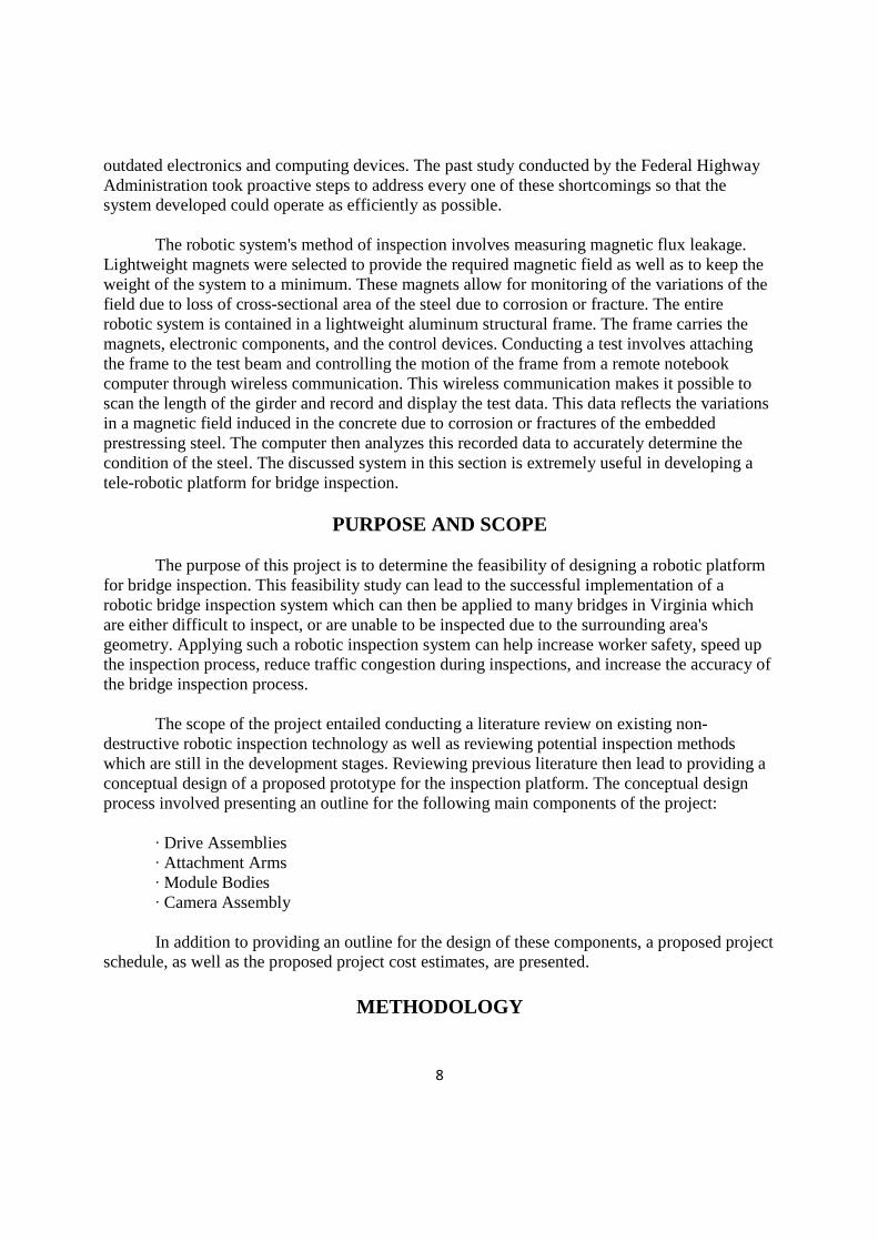
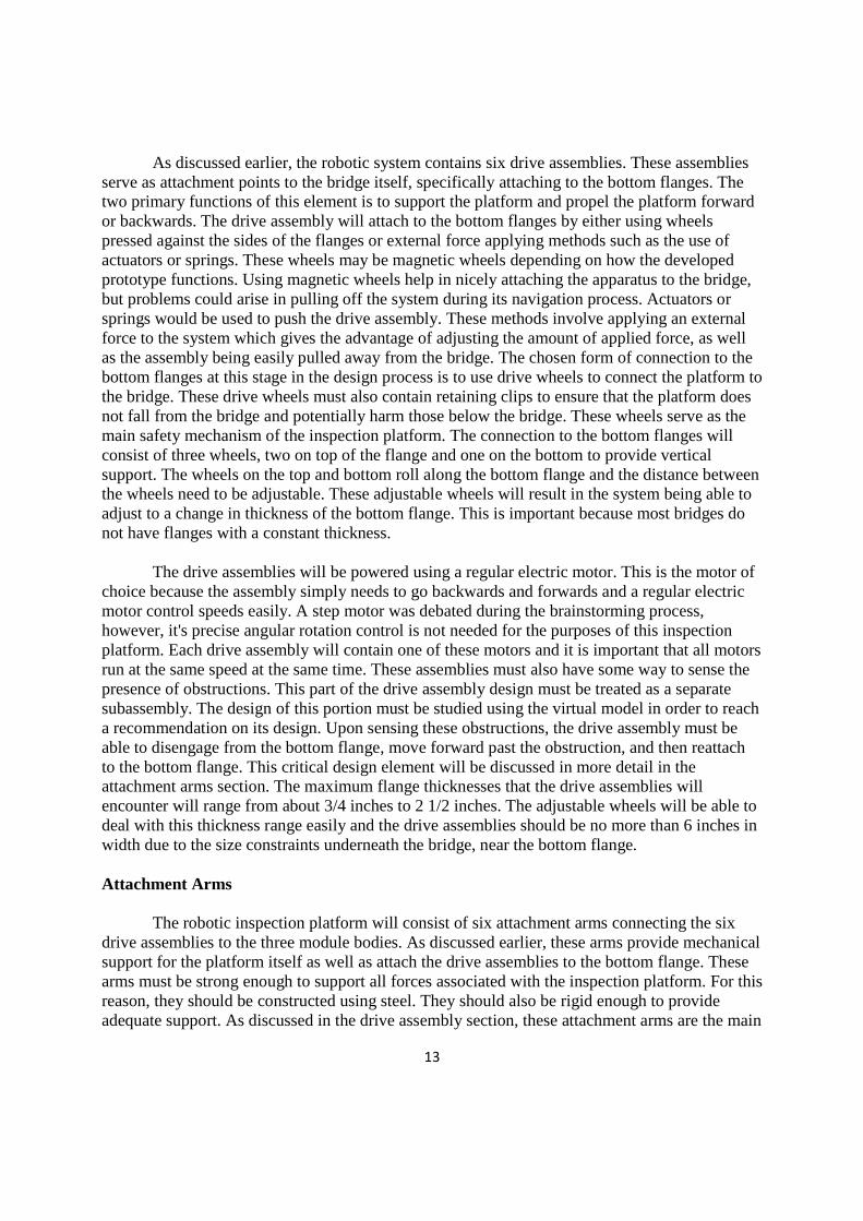
The literature review conducted for this project can be seen in the literature review portion of this report. Reviewing literature on futuristic inspection techniques as well as current inspection techniques helped narrow the project scope and present what technologies are currently commercially available. 2. Establish robotic system requirements The robotic system requirements were identified through the literature review portion of the project by observing what the current bridge inspection requirements are for VDOT. Robotic system requirements were classified as either absolute requirements or desired requirements. 3. Select a bridge to implement such a system The bridge selected to implement the robotic inspection system is the route 81 bridge over the James River. This bridge was selected because it represents a typical steel girder bridge that is difficult to inspect due to the bridge spanning over the James River. This bridge will be the model bridge used in the prototype testing phase of the proposed work plan. 4. Design a proposed virtual model on the system A virtual model of the system was designed using Solid Works software. Figure 1 illustrates a Solid Works snapshot of the route 81 bridge over the James River.
Figure 1. Solid Works Snapshot of Route 81 Bridge over the James River
The inspection platform was modeled to travel along the bottom flanges of the route 81 bridge over the James River. The bridge prototype design is still in the early stages, however, using software packages such as Solid Works makes it easier to identify which prototype design is most effective in the design process. 5. Meet with VDOT for input on proposed system The project team met with Anwar S. Ahmad of the Structure and Bridge Division in VDOT in order to more accurately define the system requirements, as well as get input on the proposed conceptual design. 6. Refine conceptual design
11
The conceptual design was then refined due to the input from VDOT as well as further research on the robotic inspection process. 7. Provide project work plan including project schedule and project costs The proposed project work plan can be seen in the results and discussion section of this report. The project schedule, as well as project costs, were estimated in order to provide an outline on how the project should proceed and what funding is needed. This project schedule is subject to change and the project costs are as well. The project costs could be cut significantly through possible funding from the Federal Highway Administration as well as significantly reducing indirect costs by going through VTRC. 8. Final report The final step taken to present this robotic inspection platform project concept is preparing a finalized report. This report has been written to inform VTRC of the many advantages that a robotic inspection platform provides for VDOT and the entire inspection community. The report identifies the conceptual design of the system, as well as the project schedule and costs associated with the system.
RESULTS AND DISCUSSION
The results of this project feasibility study include a layout of the following components that are necessary to move this project forward in the near future: · Drive Assemblies · Attachment Arms · Module Bodies · Camera Assembly · Project Schedule · Project Costs These components, together, form the conceptual design of the robotic inspection platform. These components are outlined in the subsequent sections after the robotic inspection platform overview section. Conceptual Design Overview The robotic platform has four major design elements that make up the system. These major elements are the drive assembly, attachment arms, module bodies, and the camera assembly. At this stage in the design process, the platform will have three modules bodies, six attachment arms, and six drive assemblies. The drive assembly is located at the end of each attachment arm and its primary purpose is to attach the system to the bottom flanges of the bridge. The attachment arms connect the module bodies and drive assemblies and function primarily to provide mechanical support for the platform itself and attach the assembly to the
12
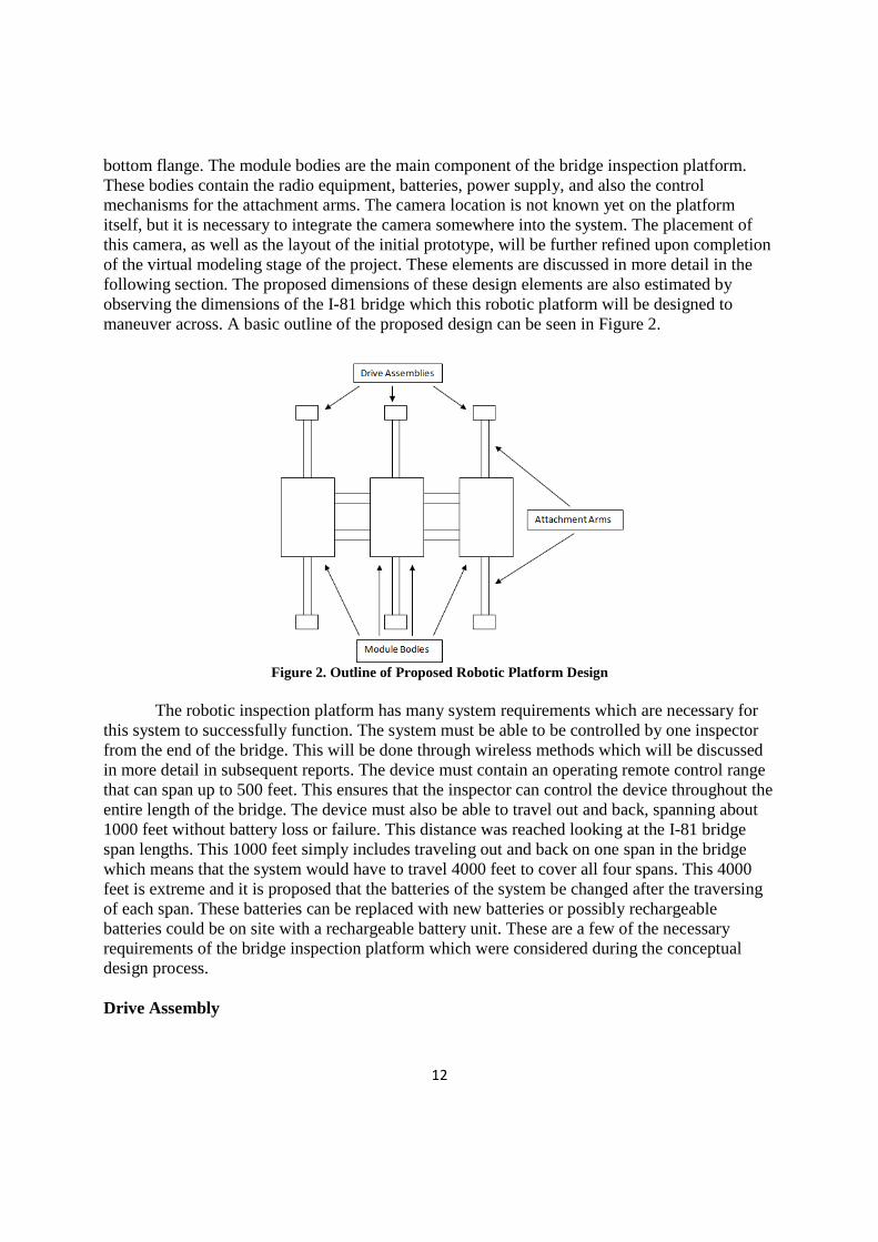
bottom flange. The module bodies are the main component of the bridge inspection platform. These bodies contain the radio equipment, batteries, power supply, and also the control mechanisms for the attachment arms. The camera location is not known yet on the platform itself, but it is necessary to integrate the camera somewhere into the system. The placement of this camera, as well as the layout of the initial prototype, will be further refined upon completion of the virtual modeling stage of the project. These elements are discussed in more detail in the following section. The proposed dimensions of these design elements are also estimated by observing the dimensions of the I-81 bridge which this robotic platform will be designed to maneuver across. A basic outline of the proposed design can be seen in Figure 2.
Figure 2. Outline of Proposed Robotic Platform Design
The robotic inspection platform has many system requirements which are necessary for this system to successfully function. The system must be able to be controlled by one inspector from the end of the bridge. This will be done through wireless methods which will be discussed in more detail in subsequent reports. The device must contain an operating remote control range that can span up to 500 feet. This ensures that the inspector can control the device throughout the entire length of the bridge. The device must also be able to travel out and back, spanning about 1000 feet without battery loss or failure. This distance was reached looking at the I-81 bridge span lengths. This 1000 feet simply includes traveling out and back on one span in the bridge which means that the system would have to travel 4000 feet to cover all four spans. This 4000 feet is extreme and it is proposed that the batteries of the system be changed after the traversing of each span. These batteries can be replaced with new batteries or possibly rechargeable batteries could be on site with a rechargeable battery unit. These are a few of the necessary requirements of the bridge inspection platform which were considered during the conceptual design process. Drive Assembly
13
As discussed earlier, the robotic system contains six drive assemblies. These assemblies serve as attachment points to the bridge itself, specifically attaching to the bottom flanges. The two primary functions of this element is to support the platform and propel the platform forward or backwards. The drive assembly will attach to the bottom flanges by either using wheels pressed against the sides of the flanges or external force applying methods such as the use of actuators or springs. These wheels may be magnetic wheels depending on how the developed prototype functions. Using magnetic wheels help in nicely attaching the apparatus to the bridge, but problems could arise in pulling off the system during its navigation process. Actuators or springs would be used to push the drive assembly. These methods involve applying an external force to the system which gives the advantage of adjusting the amount of applied force, as well as the assembly being easily pulled away from the bridge. The chosen form of connection to the bottom flanges at this stage in the design process is to use drive wheels to connect the platform to the bridge. These drive wheels must also contain retaining clips to ensure that the platform does not fall from the bridge and potentially harm those below the bridge. These wheels serve as the main safety mechanism of the inspection platform. The connection to the bottom flanges will consist of three wheels, two on top of the flange and one on the bottom to provide vertical support. The wheels on the top and bottom roll along the bottom flange and the distance between the wheels need to be adjustable. These adjustable wheels will result in the system being able to adjust to a change in thickness of the bottom flange. This is important because most bridges do not have flanges with a constant thickness. The drive assemblies will be powered using a regular electric motor. This is the motor of choice because the assembly simply needs to go backwards and forwards and a regular electric motor control speeds easily. A step motor was debated during the brainstorming process, however, it's precise angular rotation control is not needed for the purposes of this inspection platform. Each drive assembly will contain one of these motors and it is important that all motors run at the same speed at the same time. These assemblies must also have some way to sense the presence of obstructions. This part of the drive assembly design must be treated as a separate subassembly. The design of this portion must be studied using the virtual model in order to reach a recommendation on its design. Upon sensing these obstructions, the drive assembly must be able to disengage from the bottom flange, move forward past the obstruction, and then reattach to the bottom flange. This critical design element will be discussed in more detail in the attachment arms section. The maximum flange thicknesses that the drive assemblies will encounter will range from about 3/4 inches to 2 1/2 inches. The adjustable wheels will be able to deal with this thickness range easily and the drive assemblies should be no more than 6 inches in width due to the size constraints underneath the bridge, near the bottom flange. Attachment Arms The robotic inspection platform will consist of six attachment arms connecting the six drive assemblies to the three module bodies. As discussed earlier, these arms provide mechanical support for the platform itself as well as attach the drive assemblies to the bottom flange. These arms must be strong enough to support all forces associated with the inspection platform. For this reason, they should be constructed using steel. They should also be rigid enough to provide adequate support. As discussed in the drive assembly section, these attachment arms are the main
14
element that allows the inspection platform to navigate past obstructions. The arms must be able to retract, move forward, and then reattach to the bottom flanges. These arms must be adjustable, allowing them to extend and retract due to this obstruction navigation process. The range of motion of these arms does not need to be that extensive due to the minimal size of obstructions encountered. The arms only need to be able to retract about an inch due to the dimensions of these obstructions. Typical obstructions include stiffeners that extend to the end of the flange as well as bearings. A problem that may occur would be one side of the platform encountering and obstruction before the other side. Due to this fact, these arms need to all operate independently. If the obstruction is encountered at the same time on both sides, the front two arms retract, the system then moves forward past the obstruction, the arms then extend to reattach the front two drive assemblies, the system then moves forward until the middle two arms encounter the obstruction, the middle arms are retracted, the system moves forward past the obstruction, the middle arms are then extended to reattach the middle two drive assemblies, the system then moves forward until the back two arms encounter the obstruction, the back two arms are retracted, the system then moves completely past the obstruction, and then back two arms are then extended to reattach the back two drive assemblies. Although most obstructions encountered are minor, and this process, would seem to work, the system will also encounter a gap between span to span that are much more substantial in size. These gaps are about 20 inches on the I-81 bridge and this 20 inch gap plays a major role in determining the dimensions of the attachment arms. The attachment arms, at this stage in the design process, should be about 30 inches from the centerline of one are to the center line of another. This results in a 60 inch dimension from the centerline of the front attachment arms to the centerline of the back attachment arms. This dimension allows the system to have the capability of successfully maneuvering past the gap in the span to span dimensions of the I-81 bridge as well as providing it the capability to move past minor obstructions such as the ones discussed earlier in this section. The distance between the flanges on the bridge directly affect the arm length needed for the inspection platform. The I-81 bridge has a span from girder to girder of 4 @ 7'9" and the flanges also have a length which varies across the bridge. The estimated lengths of these arms are 1 1/2 feet from each side of the module bodies. The module bodies will be discussed in the next section, however, it is necessary in this section to address their proposed width of 2 feet. The arms will span 1 1/2 feet from each side resulting in the system measuring about 5 feet in width. These dimensions of the attachment arms allows the system so span the bridge length and successfully attach itself to the bottom flange. Module Bodies The module bodies are the main component of the bridge inspection platform. The proposed design results in three module bodies in order to minimize the size and weight of the system. These bodies contain vital equipment regarding the inspection unit such as radios, batteries, the power supply, and control mechanisms for the attachment arms. The camera will also be attached to one of the module bodies although its precise location will have to be
15
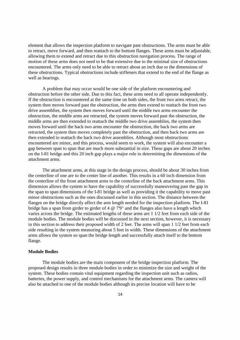
determine through prototype testing. The main challenge regarding the module bodies is the harsh size restriction underneath the bridge. The module bodies will move along the bridge via the drive assemblies movement and will be suspended between the two bottom flanges. The I-81 bridge design has been considered in this step of the design process to summarize the types of obstructions that the module bodies would typically encounter. Every 20 feet the system will encounter bottom cords which are 3 inches above the top of the bottom flange. For this reason, the attachment arms are needed to be placed toward the top of the box so that the box can clear the diaphragms. These arms only need to be placed about three inches above the centerline of the box in order to accomplish this goal of moving past the obstruction. Also, the distance that the platform drops below the bottom flanges should be kept to a minimum in case of close clearance with the road below. At this stage, the box thickness is estimated at about 6 inches. The two beams used to connect the system should about 6 feet long in order to span the length of the majority of the inspection platform. Also, the material used to encase the equipment in these module bodies should be rugged due to the harsh environment that they will encounter on a day-to-day basis. Due to the bodies needing space for all of the motors and mechanisms of the inspection platform, the proposed dimensions are 2 feet in width, 6 feet in total inspection unit length, and 6 inches in depth. These bodies can be individually placed on the bridge and then connected to each other via two beams. These beams can be seen in the figure in the conceptual design introduction. The middle box would be placed on the bridge first and attached to the bottom flange, the beams would then be slid in, the end boxes would then be placed in and attached to the middle box in order to complete the construction of the system. Camera Assembly At this stage in the project timeline, the camera placement, as well as camera selection, are not yet know. The camera must be identified and evaluated during the prototype design process as well as integrated into the system. Many cameras have been observed through a literature review and it is recommended that the selected camera be controlled via wireless methods and the camera must have the capability to present a digital image of the selected inspection location. Figure 3 shows a potential view from the onboard camera. Figure 3 is from Solid Works and represents the dimensions of the route 81 bridge over the James River.
Figure 3. View of Bridge from Onboard Camera
A digital camera is preferred because the images are much higher resolution and easier to work with and wireless control methods are needed because a power line is not feasible on a project where the platform will travel long distances away from the controller. The dimensions of the camera should be kept to a minimum, however, the proposed dimensions will be more accurately estimated upon further investigation through the virtual modeling of the prototype.
16
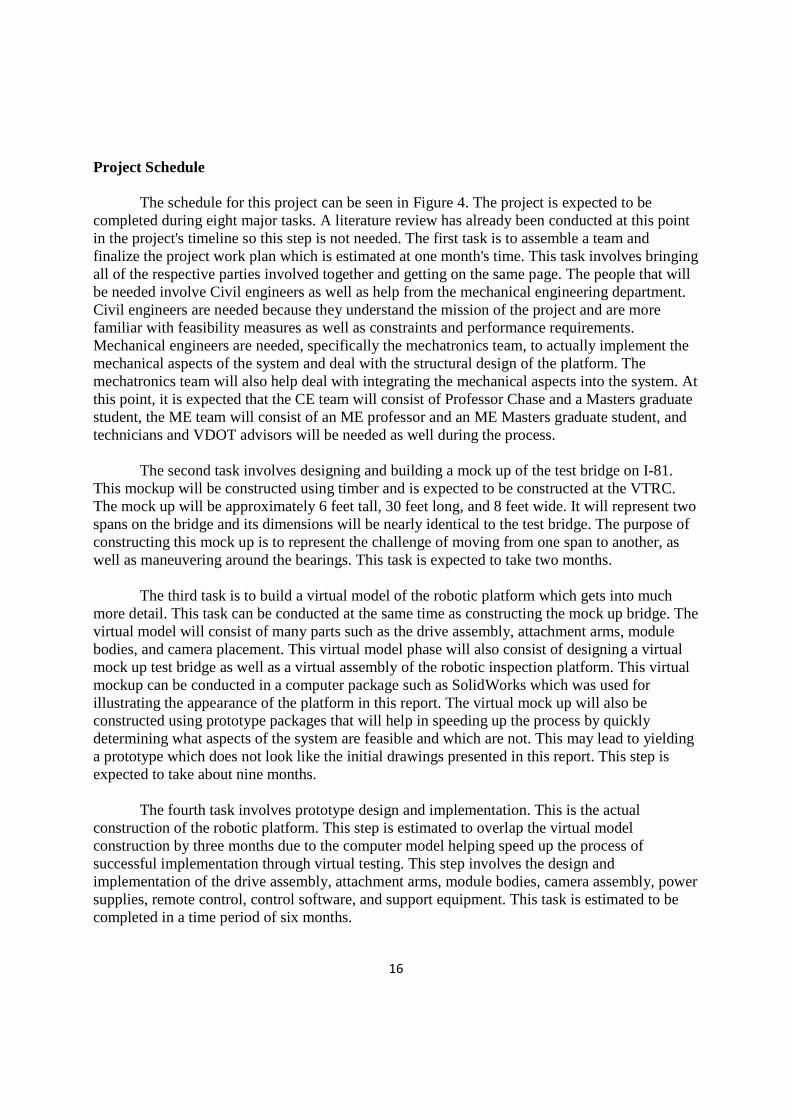
Project Schedule The schedule for this project can be seen in Figure 4. The project is expected to be completed during eight major tasks. A literature review has already been conducted at this point in the project's timeline so this step is not needed. The first task is to assemble a team and finalize the project work plan which is estimated at one month's time. This task involves bringing all of the respective parties involved together and getting on the same page. The people that will be needed involve Civil engineers as well as help from the mechanical engineering department. Civil engineers are needed because they understand the mission of the project and are more familiar with feasibility measures as well as constraints and performance requirements. Mechanical engineers are needed, specifically the mechatronics team, to actually implement the mechanical aspects of the system and deal with the structural design of the platform. The mechatronics team will also help deal with integrating the mechanical aspects into the system. At this point, it is expected that the CE team will consist of Professor Chase and a Masters graduate student, the ME team will consist of an ME professor and an ME Masters graduate student, and technicians and VDOT advisors will be needed as well during the process. The second task involves designing and building a mock up of the test bridge on I-81. This mockup will be constructed using timber and is expected to be constructed at the VTRC. The mock up will be approximately 6 feet tall, 30 feet long, and 8 feet wide. It will represent two spans on the bridge and its dimensions will be nearly identical to the test bridge. The purpose of constructing this mock up is to represent the challenge of moving from one span to another, as well as maneuvering around the bearings. This task is expected to take two months. The third task is to build a virtual model of the robotic platform which gets into much more detail. This task can be conducted at the same time as constructing the mock up bridge. The virtual model will consist of many parts such as the drive assembly, attachment arms, module bodies, and camera placement. This virtual model phase will also consist of designing a virtual mock up test bridge as well as a virtual assembly of the robotic inspection platform. This virtual mockup can be conducted in a computer package such as SolidWorks which was used for illustrating the appearance of the platform in this report. The virtual mock up will also be constructed using prototype packages that will help in speeding up the process by quickly determining what aspects of the system are feasible and which are not. This may lead to yielding a prototype which does not look like the initial drawings presented in this report. This step is expected to take about nine months. The fourth task involves prototype design and implementation. This is the actual construction of the robotic platform. This step is estimated to overlap the virtual model construction by three months due to the computer model helping speed up the process of successful implementation through virtual testing. This step involves the design and implementation of the drive assembly, attachment arms, module bodies, camera assembly, power supplies, remote control, control software, and support equipment. This task is estimated to be completed in a time period of six months.
17
The next task is lab testing. This will involve testing the robotic platform in the lab on the mock up test bridge made out of timber. Observations will occur by the design team and the platform design will be refined as necessary. This task is estimated to be completed in a time frame of three months. Next the field testing will occur which will involve many trips to the I-81 bridge that the mock up was modeled after. This testing will also lead to refining the platform design as necessary. This task will take three months. The next task is demonstration and delivery which will involve a public showing of the platform at work on the I-81 bridge as well as a speech making those present aware of the system's capabilities. This task is expected to take three months to be ready to successfully show the system. The final task is writing a final report on the platform. This will involve design specifications as well as many other explanations regarding the platform's capabilities and test results. This task is expected to take two months. The entire project is expected to be completed in 24 months. These time tables are subject to change due to the advancements or setbacks that may occur during the project's lifetime but Figure 4 represents the expected project timeline.
0 4 8 12 16 20 24
Assemble Team
Design and Build Mock up
Build a Virtual Model
Prototype Design and Implementation
Lab Testing
Field Testing
Demonstration and Delivery
Final Report
Task Duration (Months)
Figure 4. Project Gantt Chart Timeline
CONCLUSIONS
18
· The paper has shown that the construction of a tele-robotic platform for bridge inspection is feasible. Although the development of new technologies to construct such a system are not realistic, the components of such an inspection system are readily available.
RECOMMENDATIONS
1. The Virginia Transportation Research Council should fund the tele-robotic inspection platform project which would reduce the indirect costs associated with the project. 2. VDOT's Structure and Bridge Division should consider the use of such a robotic inspection system for many of the hard to inspect bridges located throughout Virginia.
COSTS AND BENEFITS ASSESSMENT
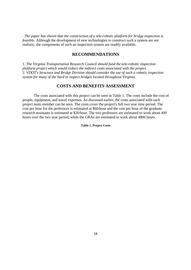
The costs associated with this project can be seen in Table 1. The costs include the cost of people, equipment, and travel expenses. As discussed earlier, the costs associated with each project team member can be seen. The costs cover the project's full two year time period. The cost per hour for the professors is estimated at $60/hour and the cost per hour of the graduate research assistants is estimated at $20/hour. The two professors are estimated to work about 400 hours over the two year period, while the GRAs are estimated to work about 4800 hours.
Table 1. Project Costs
19
PI GRA
Task 1 160
Task 2 40
Task 3 40
Task 4 20
Task 5 40
Task 6 60
Task 7 2000
Task 8 580
Total 0 2940
Estimated Budget
PI(1) 400 60 24000
PI(2) 400 60 24000
Allowance for salary increase $1,104.00
Fringe benefits - 26.9% $12,912.00
Graduate Research Assistant
4800 20 96000
Allowance for salary increase $2,208.00
Tuition Remission - In-state tuition remission $80,000.00
Health Insurance for GRA $8,000.00
Materials & equipment 70000
Total Direct Costs $318,224.00
F&A (Indirect Costs) = 52.5% $167,067.60
travel 3000
Total $488,291.60 These 4800 hours take into account the GRAs working part time during the academic year and full time during the summer. The main cost of this project is associated with the tuition remission for the GRAs which is estimated at $80,000. Materials and equipment costs were estimated at about $70,000. This cost covers the camera system, batteries, remote control system, imbedded computers, electronics, and mechanical parts associated with the bridge inspection platform. The travel expenses were estimated at $3,000 which covers four overnight trips of three people to the I-81 bridge site as well as $1,000 for conference attendance. The final project cost is estimated at about $488,000. The proposed project costs are only an estimate of the bridge inspection project. This final project cost can be reduced significantly if VTRC chooses to fund this project. This would cause the indirect cost percentage to go from 52.5% to about 12%, consequently reducing the cost from $488,000 to about $359,000. Also, the cost could be significantly reduced if the Federal Highway Administration chooses to help fund this project due to the potentially large positive impacts it would have on the bridge inspection process. VDOT Equipment Cost Savings
20
The current VDOT bridge inspection process involves many support staff members executing various tasks. The Route 81 bridge would involve closing each lane down for about six hours, spanning two days, in order to inspect each side of the bridge over the entirety of its length. There are also many pieces of equipment needed in order to conduct a safe and accurate bridge inspection process. The work zone must first contains many barrels which clearly outline that one of the lanes is closed during the process. Signs must be placed far in advance to direct traffic safely to the appropriate lane. Two to three VDOT employees must also be supporting the work zone throughout the life of the inspection process to ensure the worker's safety. A barrier truck must also be used in order to block off car from potentially entering the work zone. The inspection truck itself is needed as well in order to lower the inspector to the underside of the bridge. These trucks are not readily available and there are only a few of them across the state. A VDOT employee is needed to operate the inspection truck and a bridge inspector is needed to be inspecting the underside of the bridge. These discussed pieces are a bare minimum for the inspection process and result in significant equipment costs to VDOT. Using a robotic inspection system would not only leave the roadway open, it would cut the inspection process length significantly due to the truck not needed to move continually to observe the entirety of the bridge length.
Roadway User Cost Savings
As discussed earlier, the bridge inspection process leads to high equipment costs to VDOT, however, it can also potentially lead to roadway user costs as well. Reducing the Route 81 bridge to one lane for six hours, over two days, will result in a significant capacity reduction. This reduction in capacity can lead to the formation of a queue at the bridge, losing roadway users valuable time. The software package QuickZone was used to estimate and quantify work zone delays and user costs associated with such a bridge closure. The QuickZone package was created by the Federal Highway Administration as an easy to use analytical tool allowing for quick and flexible estimation of work zone delays. The software employs a range of Excel dialog and worksheets and the tutorial outlined in the User Guide gives step by step instructions on how to use the program. Inputting the requested information results in four printable output screens which are a project delay summary, travel behavior summary, life-cycle delay costs, and a summary table. QuickZone Beta Version 0.99 was used for this project. A simple network was constructed using QuickZone to illustrate the delays and costs associated with the bridge inspection process. The network, consisting of links and nodes, was programmed for quantifying the impact on I-81 by changing various parameters such as link volumes and link capacities. This network can be seen in Figure 5.
21
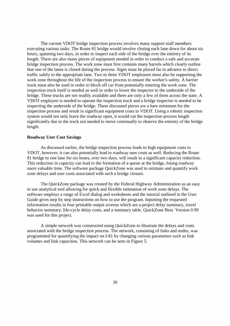
Figure 5. Screen Shot of QuickZone Network
As can be seen in Figure 5, the red area illustrates the I-81 bridge workspace, whereas the blue area illustrates the detour route. The light green area illustrates the southbound and northbound approaches. The network above is simple, but it yields an estimate to quantify delays at the section of interest on Route 81. The dark blue detour route represents Route 11/Main Street at the study area. The analysis was conducted with one lane closed in the Southbound direction. The links and nodes of this network were defined by distance, volume, and speed. It is assumed that the free flow speed over the bridge is 70 mph while the free flow speed on the detour route is 30 mph. The goal of using QuickZone, for our purposes, is to quantify the user delay costs spanning one inspection period of six hours, over two days, on the I-81 bridge. The link volumes were determined through the VDOT website looking at traffic volumes estimates for Botetourt County in 2008. This location is near the Roanoke, Virginia line and is closest to the Route 81 bridge of interest. The one way link AADT for Route 81 south across this section is estimated at 16,000 vehicles per day with a truck percentage of 32% (Botetourt, 2009). This truck percentage is needed to quantify the user costs per day in QuickZone. The cost of delay per vehicle was input as $11.84/hr by assuming that the delay cost for a passenger car is $8/hr while the delay cost for a truck is $20/hr. The truck percentage is also used to input an equivalent passenger car volume. QuickZone simply asks for a volume input, so it is necessary to calculate and equivalent passenger car volume. One truck is equivalent to approximately 3.5 passenger cars. Multiplying the truck volumes by 3.5 and adding them to the 68% passenger cars yields and equivalent volume of about 28,000 vehicles per day. This value will be used as the volume input into QuickZone. A project length is also needed in the QuickZone software. It will only allow for a minimum of one week inspection time so the inspection was programmed to span one work week, over a Wednesday and a Thursday for six hours each day between 9 am to 3 pm. The equivalent passenger car volume at the location of interest is 28,000 vehicles per day. This input value was averaged across the hours of the day using QuickZone default average percentages taken from AASHTO. The bridge contains two lanes, with a capacity of 1200 vehicles per hour, per lane. The QuickZone analysis reduced the capacity of the Southbound
22
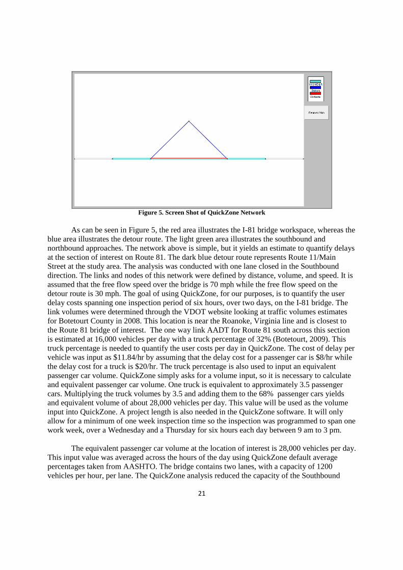
direction by 1200 vehicles per hour, per lane, effectively reducing the capacity to that of one lane. This reduction in capacity will lead to long queue lengths, increasing the roadway user delay costs. The QuickZone system was then run to produce various tables to quantify the delay caused by this inspection process. Figure 6 illustrates the delay graph for the inspection process.
Figure 6. Delay Graph
As can be seen in Figure 6, the delay occurs during the inspection hours on Wednesday and Thursday. The delay steadily rises after the 9 am inspection start time and steadily decreases after the end inspection time around 3 pm.
23
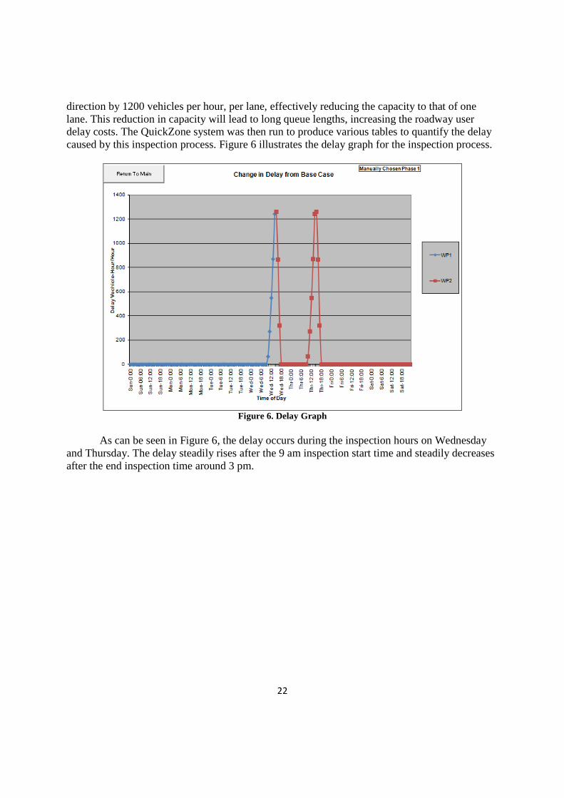
Figure 7. Project Cost
Figure 7 illustrates the cost of the inspection project. The 0.01 million is the infrastructure cost, but the roadway user cost is estimated at 0.13 million, or $130,000. This is the total cost to the roadway users for one inspection. Table 2 shows a summary of values calculated through the QuickZone simulation.
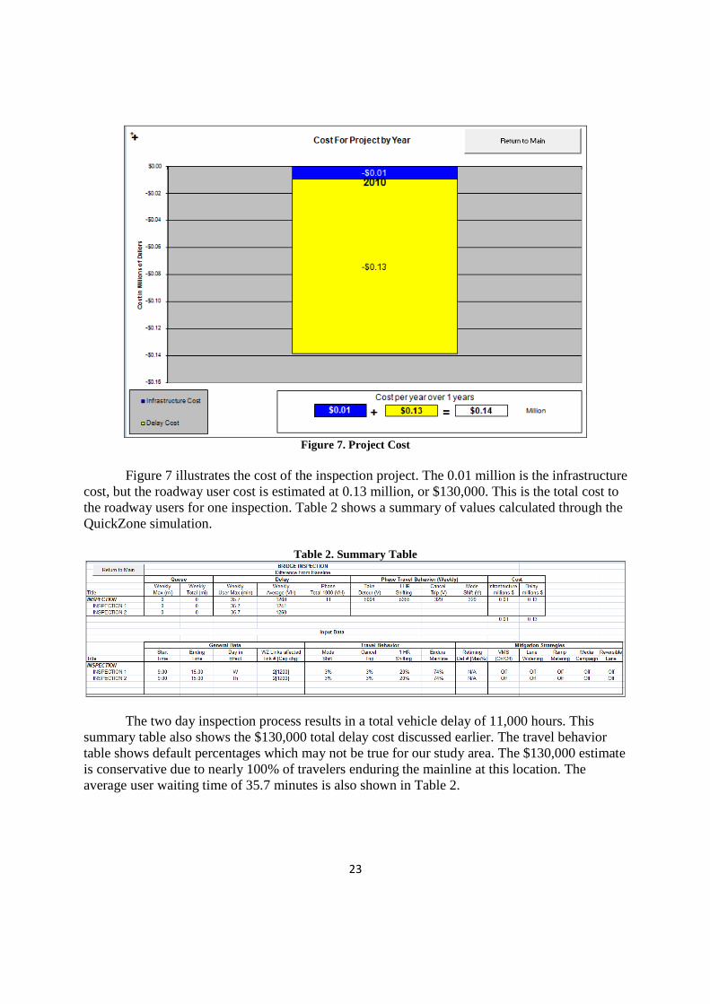
Table 2. Summary Table
The two day inspection process results in a total vehicle delay of 11,000 hours. This summary table also shows the $130,000 total delay cost discussed earlier. The travel behavior table shows default percentages which may not be true for our study area. The $130,000 estimate is conservative due to nearly 100% of travelers enduring the mainline at this location. The average user waiting time of 35.7 minutes is also shown in Table 2.
24
Summary The proposed project cost is currently around $490,000. This cost can be cut significantly down to about $359,000 through VTRC funding and FHWA could also potentially help in the funding process. The cost savings of such a system can be divided up into VDOT inspection support equipment savings as well as roadway user savings. As discussed earlier, the current VDOT bridge inspection process involves many staff members as well as inspection related equipment. The proposed inspection platform will be able to be used time and time again. The roadway user costs were also discussed and the QuickZone delay software was used to quantify the effects of closing down one lane during the bridge inspection process. The results showed that the average inspection costs users about $130,000. This could lead to the conclusion that roadway users are greatly affected, however, there is another item to consider. Motor vehicle travel through a work zone has also been shown to increase the risk of a crash. Between 50-75% of crashes are due to multiple vehicle collisions, with the next most common crash type is collisions with fixed objects in the construction site, most evidently at night (Sorock, 1996). These crashes occur mainly due to driver inattention, failure to yield right-of-way, following too close, and traveling at unsafe speeds. Work zone traffic measures can also lead to road user fatalities. Virginia alone has seen 98 fatalities occur in the construction zone from 2004-2008, with a peak of 30 fatalities in the year 2005 alone (Work, 2010). These instances may seem rare, but when they do occur, they result in an extreme cost due to the loss of a life. The use of a bridge inspection platform for bridge inspection would eliminate the need to have a work zone which would result in the roadway users' chances of an accident, or potentially a fatality, reducing. Also, the volume across the bridge could be much greater for other bridge locations. A significant rise in capacity would lead to a much higher cost to the users during the inspection process. As it stands, conducting an inspection over the Route 81 bridge three or four times would more than pay for the cost of an inspection platform. The costs associated with this robotic inspection platform are high, but the ability to use the platform repeatedly, as well as the benefits to VDOT and roadway users, prove that this project will result in a benefit to all parties affected by the bridge inspection process. Conclusions The proposed robotic inspection system may have a high development cost, but this high cost is offset by its large benefits. Bridges which have not been able to be inspected due to high traffic volume of harsh conditions can now be inspected using the proposed system. Also, the system can be applied to bridges over and over throughout the bridge's lifetime. This will also lead to VDOT successfully monitoring each bridge so that a bridge failure that is not expected, will not occur. These rare, but catastrophic events, cost a great deal of money when they occur as well potentially result in a significant loss of life. The benefits associated with such a robotic inspection system result in significant cost savings to VDOT as well as the roadway users during the bridge inspection process.
25
ACKNOLEDGEMENTS
This work was conducted in collaboration between faculty and students at the University of Virginia. The system requirements were accurately identified through collaboration with VDOT, specifically Anwar S. Ahamad out of the Central office in Richmond.
REFERENCES
About the phoenix hexapod walking robot. (2008). Retrieved September 10, 2009, from http://www.lynxmotion.com/Category.aspx?CategoryID=117 Balaguer, C., Gimenez, A., & Jordon, A. (2005). Climbing robots' mobility for inspection and maintenance of 3D complex environments. Autonomous Robots, 18(2), 157-169. Botetourt County Traffic Data. (2009). Virginia Department of Transportation. Retrieved June 20, 2010, from http://www.virginiadot.org/info/resources/AADT_011_Botetourt_2008.pdf. Desbats, P., Geffard, F., Piolain, G., & Coudray, A. (2006). Force-feedback teleoperation of an industrial robot in a nuclear spent fuel reprocessing plant. Industrial Robot, 33(3), 178- 186. Ghorbanpoor, A., Borchelt, R., Edwards, M., & Salam, E. (2000). Magnetic-based NDE of prestressed and post-tensioned concrete members - the MFL system (Final Report No. FHWA-RD-00-026). McLean, VA: Federal Highway Administration. Homans, S. (2002). Digital clay. Retrieved September 20, 2009, from http://www2.parc.com/spl/projects/modrobots/lattice/digitalclay/index.html Jiang, B., & Mamishev, A. V. (2002). Robotic platform for monitoring underground cable systems. IEEE/PES Transmission and Distribution Conference, 2, 1105-1109. Kalra, L. P., & Gu, J. (2007). An autonomous self contained wall climbing robot for non- destructive inspection of above-ground storage tanks. Industrial Robot, 34(2), 122-127. Kanaikin, V. A., Loskutov, V. E., Matvienko, A. F., & Patramanskii, B. V. (2007). A pig introscope for inspection of main gas pipelines. Russian Journal of Nondestructive Testing, 43(7), 423-426. Katranik, J., Pernu, F., & Likar, B. (2008). New robot for power line inspection. 2008 IEEE International Conference on Robotics, Automation and Mechatronics, RAM 2008, September 21, 2008 - September 24, 1195-1200.
26
Luk, B. L., Cooke, D. S., Galt, S., Collie, A. A., & Chen, S. (2005). Intelligent legged climbing service robot for remote maintenance applications in hazardous environments. Robotics and Autonomous Systems, 53(2), 142-152. Ma, Z., Hu, Y., Huang, J., Zhang, X., Wang, Y., Chen, M., et al. (2007). A novel design of in pipe robot for inner surface inspection of large size pipes. Mechanics Based Design of Structures and Machines, 35(4), 447-465. Menegaldo, L. L., Nunes Ferreira, G. A., Francisco Santos, M., & Guerato, R. S. (2009). Development and navigation of a mobile robot for floating production storage and offloading ship hull inspection. IEEE Transactions on Industrial Electronics, 56(9), 3717-3722. Oh, J., Jang, G., Oh, S., Lee, J. H., Yi, B., Moon, Y. S., et al. (2009). Bridge inspection robot system with machine vision. Automation in Construction, 18(7), 929-941. Oh, J., Lee, A., Oh, S. M., Choi, Y., Yi, B., & Yang, H. W. (2007). Design and control of bridge inspection robot system. 2007 IEEE International Conference on Mechatronics and Automation, ICMA 2007, August 5, 2007 - August 8, 3634-3639. Roman, H. T., & Pellegrion, B. (1993). Pipe crawling inspection robots: An overview. IEEE Transactions on Energy Conversion, 8(3), 576-583. Schempf, H., Chemel, B., & Everett, N. (1995). Neptune: Above-ground storage tank inspection robot system. IEEE Robotics and Automation Magazine, 2(2), 9-15. Shang, J., Bridge, B., Sattar, T., Mondal, S., & Brenner, A. (2008). Development of a climbing robot for inspection of long weld lines. Industrial Robot, 35(3), 217-223. Sheth, P. N. USE OF ROBOTICS FOR NONDESTRUCTIVE INSPECTION OF STEEL HIGHWAY BRIDGES AND STRUCTURES. Sorock, G. S., Ranney, T. A., & Lehto, M. R. (1996). Motor vehicle crashes in roadway construction work zones: An analysis using narrative text from insurance claims. Accident Analysis & Prevention, 28(1), 131-138. Suh, J. W., Homans, S. B., & Yim, M. (May 2002). Telecubes: Mechanical design of a module for self-reconfigurable robotics. International Conference on Robotics and Automation, , 4095-4101. Suzuki, M., Yukawa, T., Satoh, Y., & Okano, H. (2007). Mechanisms of autonomous pipe- surface inspection robot with magnetic elements. 2006 IEEE International Conference on Systems, Man and Cybernetics, October 8, 2006 - October 11, , 4 3286-3291.
27
Toussaint, K., Pouliot, N., & Montambault, S. (2009). Transmission line maintenance robots capable of crossing obstacles: State-of-the-art review and challenges ahead. Journal of Field Robotics, 26(5), 477-499. Tung, P. -., Hwang, Y. -., & Wu, M. -. (2002). The development of a mobile manipulator imaging system for bridge crack inspection. Automation in Construction, 11(6), 717-729. Turner, J. (2009). Research and development at NASA. Retrieved September 8, 2009, from http://www.sti.nasa.gov/tto/Spinoff2005/rd.html Vaganay, J., Elkins, M., Esposito, D., O'Halloran, W., Hover, F., & Kokko, M. (2006). Ship hull inspection with the HAUV: US navy and NATO demonstrations results. OCEANS 2006, September 18, 2006 - September 21, Vaganay, J., Elkins, M. L., Willcox, S., Hover, F. S., Damus, R. S., Desset, S., et al. (2005). Ship hull inspection by hull-relative navigation and control. MTS/IEEE OCEANS, 2005, September 18, 2005 - September 23, , 2005 Wang, X., & Xu, F. (2007). Design and experiments on cable inspection robot. 33rd Annual Conference of the IEEE Industrial Electronics Society, IECON, November 5, 2007 - November 8, 2870-2875. Work Zone Fatalities. (2010). The National Work Zone Safety Information Clearinghouse. Retrieved June 10, 2010, from http://www.workzonesafety.org/crash_data/workzone_fatalities Yu, S., Jang, J., & Han, C. (2007). Auto inspection system using a mobile robot for detecting concrete cracks in a tunnel. Automation in Construction, 16(3), 255-261.