Embed Size (px)
Citation preview
Remote Underwater Robotic Inspection
Darby Magruder
NASA-JSC
Robotic Systems Technology Branch
Presentation Overview
• Overview of Robotic Systems Technology Branch
• Project Background – Robot Inspection
• Hardware Description
• Operator Console
• Testing
• Q & A
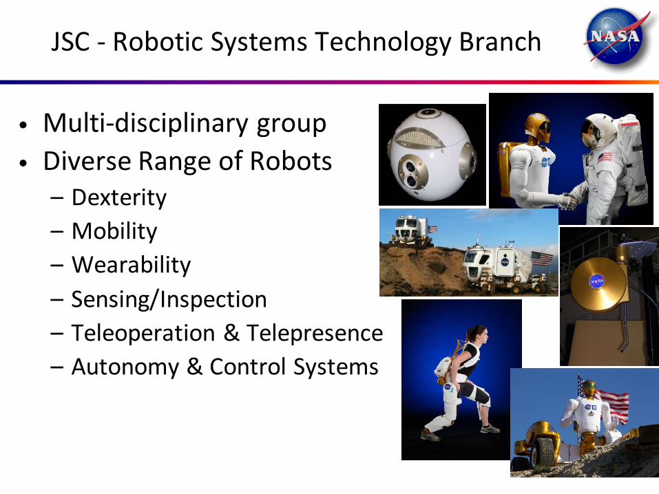
JSC - Robotic Systems Technology Branch
• Multi-disciplinary group
• Diverse Range of Robots – Dexterity
– Mobility
– Wearability
– Sensing/Inspection
– Teleoperation & Telepresence
– Autonomy & Control Systems
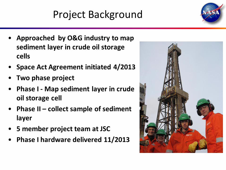
Project Background
• Approached by O&G industry to map sediment layer in crude oil storage cells
• Space Act Agreement initiated 4/2013
• Two phase project
• Phase I - Map sediment layer in crude oil storage cell
• Phase II – collect sample of sediment layer
• 5 member project team at JSC
• Phase I hardware delivered 11/2013
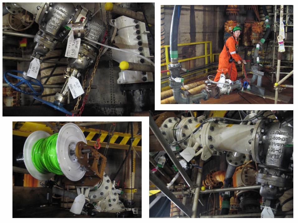
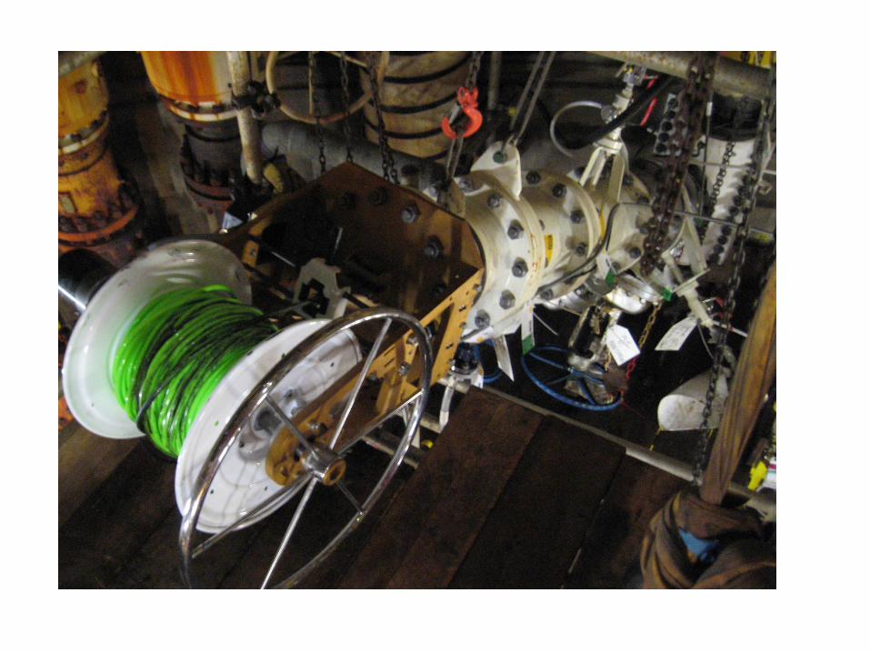
Function of Inspection Robot
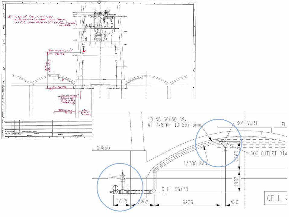
• Gain access to cell via existing 10” fill lines
• Introduce sonar mapping unit into fill lines through hot tap gate valve
• Tethered sonar propelled through pipe work via 4” forced water delivery
• Manual deploy and retrieval via tether spool external to gate valve
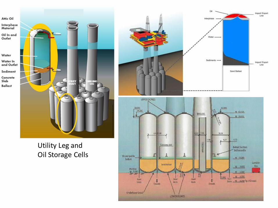
Utility Leg and Oil Storage Cells
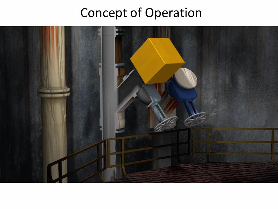
Concept of Operation
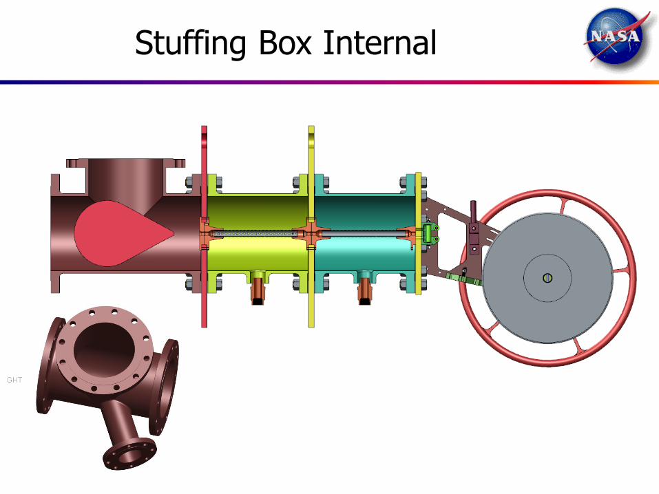
Stuffing Box Internal
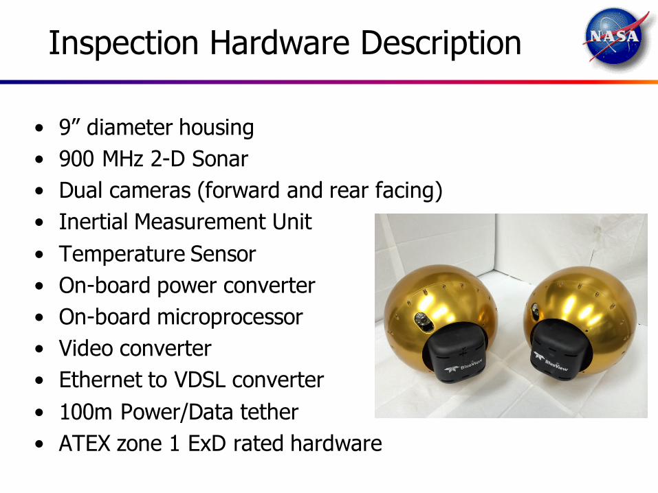
• 9” diameter housing
• 900 MHz 2-D Sonar
• Dual cameras (forward and rear facing)
• Inertial Measurement Unit
• Temperature Sensor
• On-board power converter
• On-board microprocessor
• Video converter
• Ethernet to VDSL converter
• 100m Power/Data tether
• ATEX zone 1 ExD rated hardware
Inspection Hardware Description
The technical data contained in this document is controlled under the U.S. Export Regulations; release to foreign persons may require an export authorization.
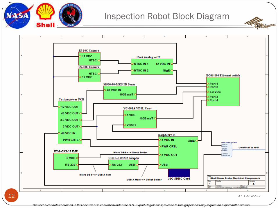
Inspection Robot Block Diagram
5/13/2013 12
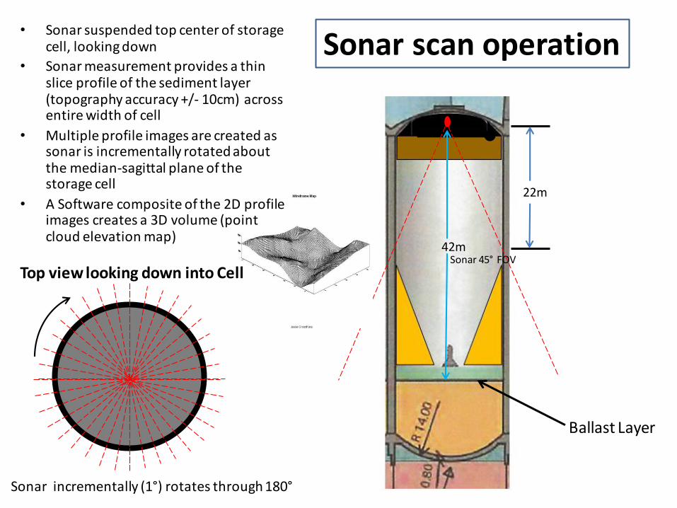
Ballast Layer
42m Sonar 45° FOV
22m
• Sonar suspended top center of storage cell, looking down
• Sonar measurement provides a thin slice profile of the sediment layer (topography accuracy +/- 10cm) across entire width of cell
• Multiple profile images are created as sonar is incrementally rotated about the median-sagittal plane of the storage cell
• A Software composite of the 2D profile images creates a 3D volume (point cloud elevation map)
Top view looking down into Cell
Sonar incrementally (1°) rotates through 180°
Sonar scan operation
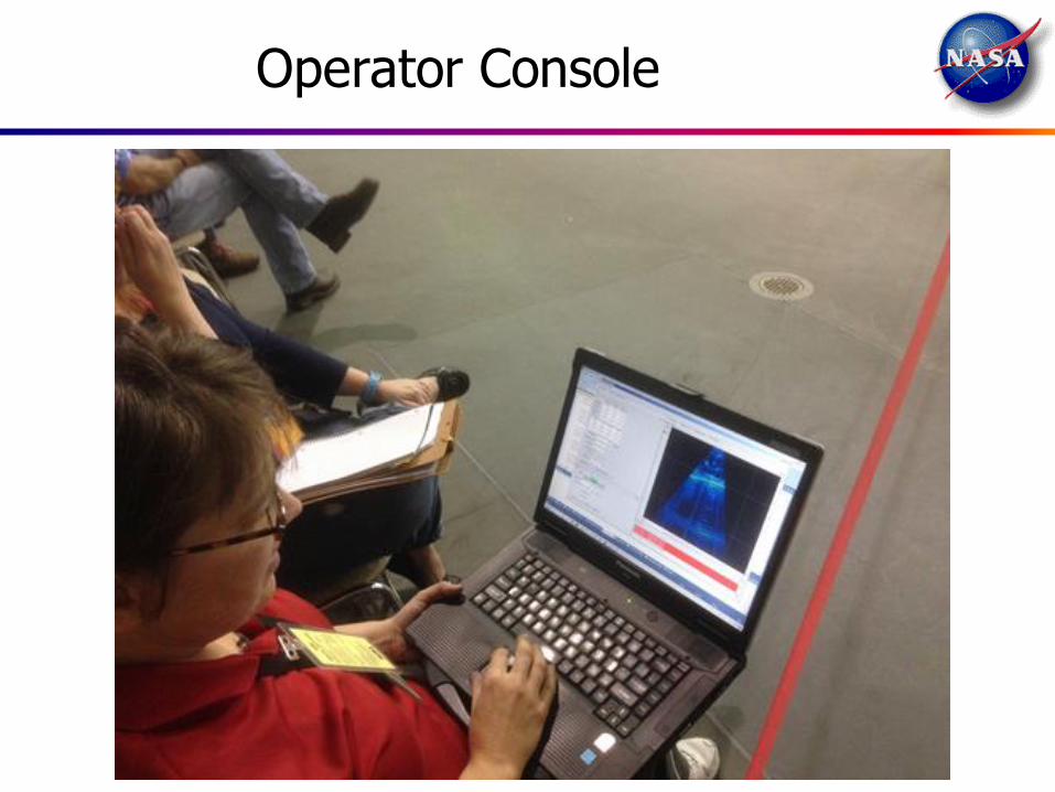
Operator Console
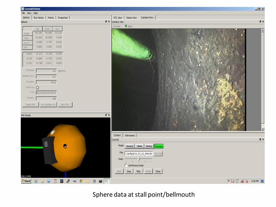
Sphere data at stall point/bellmouth
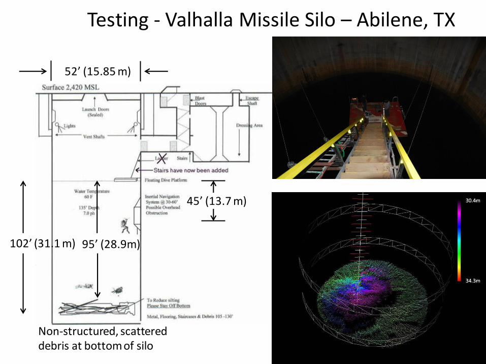
Non-structured, scattered debris at bottom of silo
95’ (28.9m) 102’ (31.1 m)
52’ (15.85 m)
45’ (13.7 m)
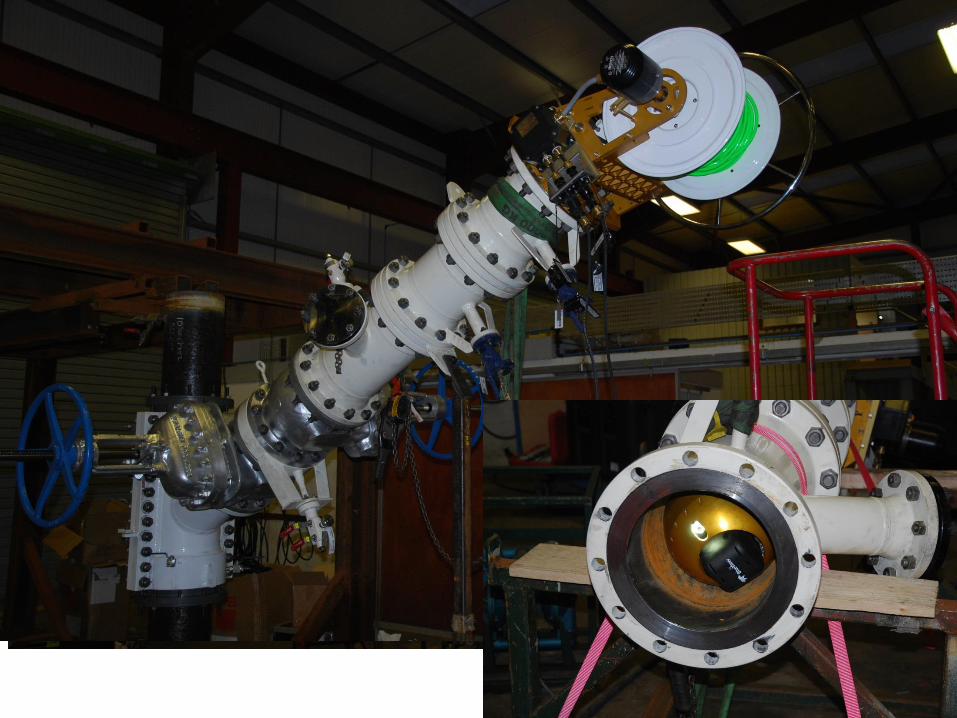
Testing - Valhalla Missile Silo – Abilene, TX
NBL Flow Testing
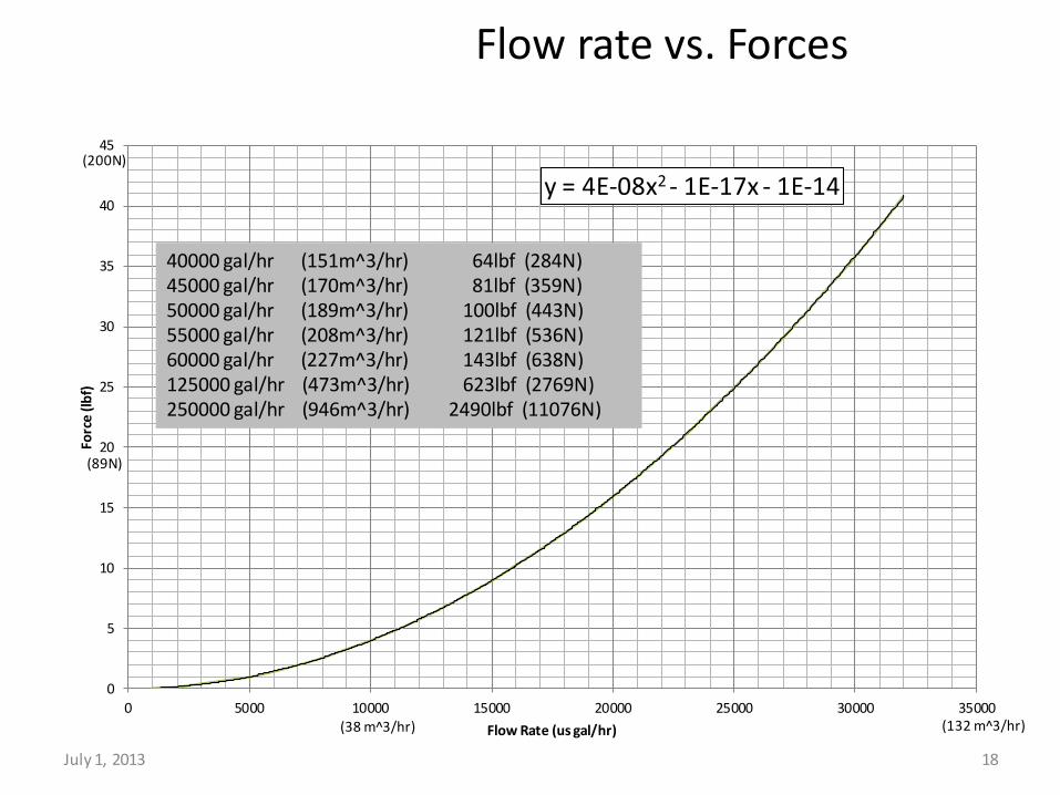
Flow rate vs. Forces
18
y = 4E-08x2 - 1E-17x - 1E-14
0
5
10
15
20
25
30
35
40
45
0 5000 10000 15000 20000 25000 30000 35000
Forc
e (l
bf)
Flow Rate (us gal/hr) (38 m^3/hr) (132 m^3/hr)
40000 gal/hr (151m^3/hr) 45000 gal/hr (170m^3/hr) 50000 gal/hr (189m^3/hr) 55000 gal/hr (208m^3/hr) 60000 gal/hr (227m^3/hr) 125000 gal/hr (473m^3/hr) 250000 gal/hr (946m^3/hr)
64lbf (284N) 81lbf (359N) 100lbf (443N) 121lbf (536N) 143lbf (638N) 623lbf (2769N) 2490lbf (11076N)
(200N)
(89N)
July 1, 2013
Q & A