Embed Size (px)
Citation preview

Deutsche LuftfahrtforschungExaminations and Notices No. 562
Reportabout strength examinations on an outer wing
of the russian airplane type Rata I16Krumbholz
drafted byDeutsche Versuchsanstalt für Luftfahrt E.V.
Institut für FestigkeitBerlin-Adlershof
Zentrale für wissenschaftliches Berichtwesender Luftfahrtforschung des Generalluftzeugmeisters (ZWB)
Berlin-Adlershof

Reportabout strength examinations on an outer wing
of the russian airplane type Rata I16
Abstract: Examinations were conducted on the material used in the parts of an outer wing of the airplane type Rata I16 for establishing the strength values and chemical composition. Strain measurements and one test to destruction gave information regarding the strength.
Content.
I. Object of inquiry.II. Scope of examinations.III. Results of the material composition examinations.
1. Tubular spar cap.2. Web sheeting.3. Riveting of web.4. Tension wires.
IV. Execution and results of the load tests on the outer wing.1. Scale and distribution of wing loads. a) Bending. b) Torsion.2. Execution of tests.3. Results of the stress- and deflection measurments on the wing. a) Bending. b) Torsion.4. Test to destruction (Bending).
V. Summary.
This report consits of:49 Pages21 Pictures
Institut für Festigkeitder
Deutschen Versuchsanstalt für Luftfahrt E.V.
Compiler:
Krumbholz signed:
Berlin-Adlerhof, the 20.Dec.1938
Translation:Volker Heydecke, Nov.2012

-2-
I. Object of inquiry.
A left hand outer wing (photo pic.2) and fragments of a spar of another outer wing were provided by the E-Stelle Rechlin (Testing grounds Rechlin).The outer wing has 2 spars and is connected to the inner wing by 4 sperical contact joints (pic.3; also schematic drawing of the sample in pic.1). The spars are constructed of drawn steel tubing spar caps and Dural- plain sheeting, riveted together. Pic.4a and b show the most important dimensions in graphical composition. To establish the cross sections of the spar caps, the spar caps were cut apart in several positions, after the test to destruction. The spar caps have one joint each: The front spar between ribs 7 and 8, the rear spar between 5 and 6. In between the sperical contact joints and the joints the outer surface of the caps is turned down conically over a long distance. Outerboard of the joints the spar caps have lightening slots, pointing towards each other. In the outer part of the wing – outboard of rib 10 – the spars are made from a Dural C-shape.
The ribs are frameworks of Dural- profile trusses and riveted to the spar caps via steel fittings. The caps of the ribs are not broken at the spars. Four ribs carry aileron repectively flap hinges and are sized to be stronger. In between those main ribs the outer wing is crossed out in the level of the upper and lower caps by steel profile wires (pic.3). The leading edge is covered with Dural- sheet, that is riveted to the ribs but not the spar caps. The leading edge cover starts at the lower cap of the front spar and exceeds the top spar cap by about half the distance to the rear spar (photo pic.2). The rest of the wing is covered in fabric. This fabric covering was alas not present at the test sample. Furthermore the landing flap was disassembled before the test.

-3-
II. Scope of examinations.
The aim of these examinations, ordered by the RLM, was to establish the load bearing capacity of the outer wing. The result should make it possible to draw conclusions about the russian design strength requirements.
First, to establish the material properties and the chemical composition, material tests were conducted on the existing spar fragments (cap and web sheeting). Furthermore the strength of the riveted connection from web to cap was examined. Next the outer wing was loaded with upwards pointing forces in such a distribution, as they are achieved in the load case 'pull up with high angle of attack'. At this loading tensile and bending deflection measurements were conducted. In a second series of tests the framework properties and loading via torsion were measured in a way, by wich front and rear spar were loaded after one another with upwards pointing forces. With the results of both series of tests the loading for any discretionary load case can be established very closely by combination, as long as the spanwise loading does not deviate substantialy from the distribution used in the tests.
For conclusion of the tests the outer wing was loaded according to the load case 'pull up with high angle of attack' to destruction. - Afterwards two spar caps and two tension wires were taken out of the wing, to establish the buckling load respectivly the tensile strength. The results of those last tests are shown in the next chapter about material property examination.

-4-
III. Results of the material composition examinations.
1. Tubular spar cap.
Two test specimen were cut out of broken fragments of a front spar upper spar cap (steel). The examination+) in a tensile testing machine and the chemical analysis showed general equality with domestic Chrom-Moly-steel VC Mo 125 (Fliegwerkstoff 1452.6), as is given in following table:
Strength data:Description Sig0,02
kg/mm2Sig0,2
kg/mm2SigB
kg/mm2E
kg/mm2Sig0,2
SigB
Delta10
%Rata
Specimen 1 66,3 117 123 20900 0,95 7,3Specimen 2 - 115 122 20600 0,94 6,5Average 66,3 116 122 20750 0,94 6,9
VC Mo 125Flieg 1452.6 - >90 >110 - - >5
Analysis:Description C Si Mn P S Cr MoRata 0,31 0,2 0,46 0,032 0,018 0,94 0,25 %VC Mo 125Flieg 1452.6
0,22+0,28 <0,350 <0,7 <0,02 <0,015 0,90
+1,200,15
+0,25 %
Furthermore the buckling strength of two spar cap specimen was established. For this one front spar lower spar cap with 2,60cm2 cross section was cut out between rib 2 end 3 and one rear spar lower spar cap with 2,15cm2 to 1,68cm2 cross section was cut out between ribs 4 and 5, after the test to destruction. Each test specimen had
----------------+) at the institute for material research

-5-
a length of 240mm, corresponding to the distance between ribs, and flat (tuched-up) end faces, into which the compression forces were introduced by steel plates. (The type of end bearing was without influence due to the small aspect ratio of the rods.) The results were:
Description Cross sectioncm2
Lengthmm
Buckling loadkg
Buckling stresskg/mm2
Front spar – lower cap 2-3
2,6 240 32600 125
Rear spar – lower cap 4-5
2,15 max1,68 min
240 16280 97+)
+) calculated with Fmin = 1,68cm2
The depletion of the strength in the first case (Front spar – lower cap 2-3) took place by buckling of the whole rod, in the second case by local buckling of the tube wall close to the thinner rod end.
2. Web sheeting.
Out of two, non adjacent, positions two specimen were cut out of the 0,75mm thick Dural web sheeting. As the strength examination and the analysis show, this material fits into the group of domestic Al-Cu-Mg alloys (Fliegwerkstoff 3115.5):
Strength data:Description SigB
kg/mm2Delta10
%Rata
Specimen 1 38,5 15Specimen 2 41,3 15Average 39,9 15
Flieg 3115.5 42 15

-6-
Analysis:Description Cu Mg Si Mn Fe ZnRata 4,14 0,74 0,60 0,60 0,48 0,07 %
Flieg 3115.5 3,7+4,7
0,4+1,0
0,1+0,7
0,3+0,7 <0,5+) <0,1 %
+) Fe + Ti
3. Riveting of web.
In a third test series the shear strength of the riveting of the web (Dural) was examined. Out of a part of the front spar 4 40mm wide Strips were cut out (sketch), in a way that 2 adjacent rivets
remained. The force vector of the force P was arranged, that all rivets (by calculation) would carry the same load. The load P was increased until failure of the riveted connection. The 4 tests had the following result:

-7-
Sample Break loadPBR
kg
Rivet – diad
mm +)
Shear cross section F= 4 Pi d2
/4
mm2
Shear strengthPBR / Fkg/mm2
comment
1 710 3,1 30,2 23,5 In each test each time 2
adjacent rivets sheared off
simultaneously
2 820 3,1 30,2 27,23 678 3,1 30,2 22,54 760 3,1 30,2 25,2
Average 742 30,2 24,6+) established after the test on the sheared rivet
The average shear strength is tau = 24,6 kg/mm2 and is only slightly below that value for domestic rivets:tau = 27 kg/mm2 nach Flieg 3115.4.
4. Tension wires.
Tensile tests on two wires of the internal wing bracing showed following results:
Description Cross sectioncm2
Break loadkg
Break stresskg/mm2
Large profile 0,2 2280 114Small profile 0,132 1412 107
Compared to those DIN L 67 demands a minimum Strength of SigBR = 118 kg/mm2 for the same size profile- tension wires.

-8-
IV. Execution and results of the load tests on the outer wing.
1. Scale and distribution of wing loads
a) Bending.
The required bending load for the tests was established by scale and distribution according to a rough calculation and based on the russian Strength requirements +). Those give the normative bending load case Av: pull up with highest lift coefficient. The break load factor nA of this case depends, as shown in pic.5, only on the highest horizontal speed vh max and the 'group', into which the plane falls according to its maximum flying weight Gmax. With the numbers for the type Rata I16 vh max = 440 km/h (at 2300m altitude) and Gmax = 1555kg (group III with Gmax<3000kg) the demand for the break load factor is nA = 11,1. (The notion of safe / limit load is not used in the USSR.) Uncertain is the relevance of groups II and I, that do not exhibit weight numbers and are apparently meant for airplanes with especially high demands. Classification of the type at hand into either group would lead to nA = 12 or 13. - The here commonly used calculation method (for quasi elliptical wings) by which the spanwise lift distribution is proportional to the profile depth, is applicable according to the russian strength requirements.
To determine the centre of lift the wing profile was measured at two sections (pic.6)– root rib 1 and rib 7 – as the profile number or polars were not known initially.The thickness distribution, as well as the chord of those two profiles are quite close to the corresponding lines of the profile
-----------------+) S.z.B. Les méthodes officielles de calcul de resistance des matériaux des avions en U.R.S.S. L'aérophile Mai-Août 1937.

-9-
NACA – CYH +), whose polares can be used for the wing at hand (pic.7). Differences are in the maximum thicknes; 11,7% for the NACA – profile, but 14,5% for rib 1 and 12% for rib 7. For Ca max the centre of lift is located at s = 0,285 t from the leading edge.
For the test a load factor of n = 3,62 was used, i.e. About one third of the minimum required break load coefficient nA = 11,1. Pic.8 shows the distribution of the lift and the residual weight force n * 35kg in spannwise direction. The resulting load was distributed according to the centre of lift position, while for simplifaction the load centre of the residual mass force was approximated at the centre of lift position (s/t = 0,285) too. Those continous spar loads were then broken into distinct loads at each rib position. Those point loads for the test, as well as the resulting shear loads and bending moments are also shown in Pic.8. At rib 12, which doesn't connect with the front spar, the point load is attached to an extension of the front spar (see Photo Pic.10).
For another bending load case the russian load assumptions (according to a foot note in the source mentioned on pg.8) know a case Bv. This Case is characterized by a smaller break load factor, which is depending on nA – in this case nB = 6.5 to 7.5 – and by the angle of attack, at which the lift coefficient is 0,2 times the highest one at case Av. For case Bv Pic.7 shows a ca = 0,26 and the centre of lift at cm/ca = 0,385 (angle of attack + 0,3deg), however the russian assumptions demand that in this case the pressure point must not be in front of the middle of the profile. Case Bv was not considered in this test, as its result can be intraploated from the authoritive bending load test (pic.8) and from the stresses from the torsion load test (see following). - For the
-------------------+) NACA Rep. 286, page 341

-10-
same reasons the load case pull up with negative angle of attack was not considered.
b) TorsionThe authoritive torsional load case in the russian strength requirements is case Cv : Dive with
ca = 0 and terminal dynamic pressure qc. For ca = 0 the moment coefficient cm , which was not measured for ca = 0, was extrapolated in Pic.7 as cm0 = 0,035. The speed to give terminal dynamic pressure qc was unknown and was estimated in regards to domestic data to vc = 700 km/h. The momental loading that the wing has to be able to just withstand according to the russian standards is mc = 2*cm0 * qc * t2. Of this half was used in the tests, that is according to the german standards the safe load. Pic.9 shows at the top the mc/2 applicable momental load. As before only the spars were loaded in this load case. For this the momental load was recalculated into bending loads, pointing downwards at the front spar and pointing upwards at the rear spar, which were then as in the case 'pull up' broken into point loads (pic.9, middle). However due to technical testing reasons not half the load of case Cv was applied, but one after another the front and the rear spar were loaded with their loads according to Pic.9 u p w a r d s.
2. Execution of tests.
The spar point loads (Pic.8 and 9) were applied exclusivly at the wing bottom. They were applied at each rip cap below the spar cap and were effected by calibrated plate weights via bellcranks (see testing apparatus in photo Pic.10). The loads on rib 1 from Pic. 8 and 9 were not applied.
The wing was connected to a vertical, considered rigid steel reinforced contrete testing wall, via a carrier frame. For this the sperical contact joint parts, that are located at the inner wing and which were missing, were newly manufactured and

-11-
rigidly mounted on the carrier frame (see Pic.10a). The wing was tensioned before the tests, that while testing no wire would be tensionless with certainty.
In the test series the loading and unloadung was carried out in 3 steps. The reading of the measurment instruments was done at each load step. Each test was repeated for checking purposes. Strain was measured at the spar caps and tension wires, at a few points also on the metall skining and at the wing tip with Huggenberger- Strain gauges (20mm measurment length), the bending deflection of the spars and further - with Zeiß dial gauges – the deflection of the fittings at the carrier frame.
In the break load cases the loading of the wing was increased per step by n =0,5.
3. Results of the stress- and deflection measurments on the wing.
a) Bending.
To establish the basic stress distribution and to check the measuring system one cross section in between ribs 3 and 4 was measured in detail. This measuring cross section was located 70mm outboard of rib 3. To avoid possible influences in the local stresses by the way the loads were applied, ribs 2 and 5 were not loaded during this test. In a pre test it was established that the skin would not buckle out at the top surface in the measurement cross section and in the adjacent areas.
Pic.11 shows the measurement cross section and the position of the strain gauges. Those were also applied on the side fibres of the spars, when those areas were approachable. At those positions the web skin was cut out for each strain gauge in the way of two

-12-
small rectagular areas (3x5 mm2). Besides those measurment points the stresses are given in g/cm2. All of the measured strains were shown to be proportional to the loads with high accuracy.
The stress distribution at the spars is – as can be determined by the measurment results – linear and anti metric to the centre of the spar. The inner bending moment, which is created solely by the spar stresses, is Mi
H = 836 kgm, while the external bending moment was Ma = 877 kgm, so that: Mi
H = 95,5 % Ma. The stresses in the tension wires are clearly smaller than their positions in the levels of upper and lower caps would suggest, due to the softness of the ribs and the fittings. The bending moment from the tension wire forces is Mi
S = 20,9 kgm = 2,4 % Ma.
The orientation and absolute value of the measured skin stresses shows, that the skin also experiences bending. An examination of the skin stresses can therefore only be done at the two measurement points behind the front spar, where in each case two tensometers where located together. Unsure is the loading of the rear trailing edge, at which only two strain gauges could be applied. The – to be seen with reservation – evaluation gives a skin force of PH = - 121 kg (Pic.11) behind the front spar; together with the compression force excess of the tension wires (- 12 kg) and the compression force in the trailing edge (- 104 kg) an excessive compression force PD = -237kg is present in the measurment cross section, which is only reacted by the tensile force Pz = + 145 kg in the trailing edge. Those numbers are only approximate, but show clearly, that the bending moment from loads in skin and trailing edge can only make up not more than 2 to 3 % Ma. - The same small share by skin and trailing edge was found in a measurment cross section in betwen ribs 7 and 8. Both constructive features were therefor not examined any further, especially considering that in the other sections the skin was visibly pre- buckled or buckled at even light loads.
In further tests, with loading according to Pic.8, the stress was measured in all tension wires and at numerous positions, distributed over the whole wing spar caps. At

-13-
each tension wire two strain gauges were located opposite each other. At each spar measuring cross section two strain gauges were located in general - one per upper cap and lower cap extreme fibre, the later sometimes omitted due to space limitations.
In Pic.12 the measured stresses from the tension wires are compiled. Pic.13 a and b show the stresses in the cap extreme fibres of both spars. Here the calculated extreme fibre stress is shown for comparisson, which is set on the assumptions, that only the spars are working, that there is no combound effect in between the spars and that the stress distribution in the spar is linear. The first two assumptions are met at least for the present load case in a practically exact way (see the results of the bending deflection tests further down), the second is confirmed by sufficiently many single tests, in which the cap stresses were established in several surface lines of one cross section (see for example Pic.11 and 14). In between the results of the calculation and the measurement in Pic.13 a and b practically certain agreement is given.
Pic.15 shows the result of the bending deflection measurments in the case ' pull up' (n = 3,62). In this picture the spar rotation, due to the flexibility of the mounting frame (established by dial gauges) (at the front spar 1,84*10-3, at the rear spar 1,19*10-3 in radian measure, oriented the same as the bending moment), is already eliminated, i.e. The i n n e r parts of the sperical contact fittings are seen as imovable. For comparisson the calculated deflection curve is also drawn in, which is neglecting shear deflection and tension wire stiffnes. For the calculation it was assumed that the wing is rigidly mounted at rib 1. This assumption does not correspond with the assumption taken for the examination of the measurement results, therefore the measured deflection curve is slightly above the calculated one. With regard to the good corellation in the calculated and measured stresses (Pic.13) the two deflection curves should also fall almost together when assuming the same rigid mounting.

-14-
b) Torsion.
As said under IV,1,b, the wing was not loaded according to the load case 'Dive', instead both spars were loaded one after the other with u p w a r d s pointing forces (spar single point loads in Pic.9, middle). Aim of the hereby made stress measurements was only, to gain an approximate overview over the distribution of the torsion moments and to examine, if in the case 'Dive' a premature destruction of the wing could be expected. Accordingly the stresses in all tension wires, but furthermore only at three cross sections of both spars were measured. For the load case 'Dive' the stresses were established by super position out of the single measurements (Pic.16; super position is applicable, as at the chosen wire pre tension – 350 to 400 kg – even while loading both spars according to the case 'Dive', all wires would have remained tensioned.)
The evaluation of the test results (Pic.17) shows in rough approximation, that in average 40% of the torque is taken by the spars via shear bending and 60% is taken as shear by the torsion tube created by the spars and tension wires. Pic.17 shows at the top the bending moments, equal by absolute value, that result, when the compound effect under load as per Pic.9, centre, is neglected, and at three positions the spar bending moments that are calculated from the spar cap tension stresses from Pic.16. In the lower illustration of Pic.17 the wing torsion moment (from Pic.9 lower) and the torsion from the measured stresses (Pic.16) from the tension wire forces is compared; the torque of the torsion tube is in average double the magnitude. - A small (not established in numbers) part of the torque is absorbed by the torsionally rigid spars themselfs.
The distribution of the torque depends on the warp of the clamping cross section. The angles of rotation of the clamp – the inboard side of the spherical contact joints – was established as 0,745*10-3 (radian) at the front spar and

-15-0,806*10-3 at the rear spar, in each case in the direction of the active bending moment. A post calculation of the inner wing, of which the main dimension are known, established that the mounting of the outer wing to the inner wing is softer, than used in the tests, and that therefore the measured cap stresses are too high in comparisson to the plane environment, the measured tension wire stresses are too small.
No further stress measurements were conducted, because based on the test results a premature failure of the wing in th case 'Dive' was not expectable. Specifically the stressing of the caps, whose strength in situ is of particular interest, is very low and averages only about one third the magnitude of the measured data for the case 'Pull up' (Pic. 13a and b). In this comparison it is to be considered further, that the test load factor of n = 3,62 is quite small, and must be multiplied by at least 1,5, so that the load that is applied in the bending and torsion case has the same magnitude as the minimum strength demanded by the russian strength requirements.
Pic.18 shows the bending curves of the spars and the twist of the wing in the case 'Dive'. To give a magnitude for the compound reaction, the bending curves for both spars are drawn in as well, for when only the rear spar is loaded. Here, too, as in the bending case, the rotation of the spars, affected by the softnes of the mounting structure, is eliminated.
4. Test to destruction (Bending).
For the test to destruction the load case was chosen, that based on the measurement results from the previous paragraph was established to to be authoritativ for the spar caps: Case Av 'Pull up with highest lift coefficient'. From the stresses measured at bending and torsion can be reasoned, that in the second considered bending case – Case Bv

-16-
with nB(failure) = 6,5 to 7,5 and centre of pressure at 50% of chord – the spar cap stresses are smaller than in the first case throughout. For the test to destruction the load distribution was the same as in the measurement tests (Pic.8). The load was stepped up by n = 0,5 each time.
Before the test to destruction a part was cut out from the upper spar cap in between ribs 3 and 4, which was shot at and could have resulted in a premature failure. The cap was replaced by a solid round at this position.
From a load factor of n = 6 tension wrinkles started to develop in the web skin of both spars. Those were first only recognizable in the front spar outboard from rib 6, in the rear spar outboard from rib 3 , but developed until load factor n = 9 over the whole length of the spars. The wing held, without showing any further anomalies, the load factor n = 18 for more than one minute without failure. As no higher load was anticipated for the testing rig, the test was terminated. The tension wrinkles in the spar webs remained after load relief, the ones in the front spar close to the wing joint and in both wings close to the cap joints especially pronounced.
At the reiteration of the test buckling occured at n = 13 in between ribs 10 and 11 and subsequently rupture of the upper flange, which is loaded under compression, of the Dural-C-section front spar segment. The wing was reliefed, the damaged spar section repaired.
In the third and last Test a load factor of n = 16,5 was held without failure. While load increase to n = 17,0 the joint of the lower cap of the front spar broke (photo Pic.19): The neck of the ball socket was ruptured on top, the ball socket almost completely pulled out of the retainer nut. Photo Pic.20 shows the joint disassembled from the wing.
The premature failure in comparison to the held load factor of the first test (n = 18) indicates, that the joint was already strained in the first test. Assuming that the established load

-17-
distribution of the wing bending moment at the load factor n = 3,62 does not change at higher loading, then the bending moment for n = 18 at rib 1 in the front spar computes to (Pic.8) M1 = 1013 kgm* 18/3,62 = 5030 kgm and the connection forces M1/h1 = ±5030/0,18 kg = ± 28000 kg (spar distance h1 out of Pic.4a). For a cross section of the neck of the ball socket of 2,7 cm2 +) the stresses compute to ± 10360 kg/cm2 for uniform stress distribution. Furthermore stresses are introduced due to bending of the neck of the ball socket, for upwards directed load tensile stresses on the top side and compressive stresses at the lower side of each joint. The failure happend on the side of the highest tensile stresses, i.e. On the top side of the lower joint. After rupture the ball socket was not loaded axial symmetricaly anymore, but only along part of its circumference, which lead to the visible deformation in Photo Pic.20.
Important assessment, that based on the measured cap stresses at n = 3,62 (Pic.13a and b) the material yield strength was reached at some positions at n = 18. Even when recognising a certain stress equalisation in the post elastic range, therefore the ultimate (break) load factor can not be much higher than n = 18.
In photo Pic.21 an especially strongly formed, characteristic tension wrinkle in the web skin of the front spar in between ribs 7 and 8 is shown. When taking the photo, which was taken immediatly after the failure of the joint, the front spar was already partially reliefed.
-----------------------+) Outer diameter 30 mm, inner diameter 23,6 mm.
The wall thicknes could not be measured directly.

-18-
V. Summary.
The strength examination on the outer wing of the type Rata I 16 was structured in material analysis of some samples and in load tests on the whole outer wing.
The m a t e r i a l a n a l y s i s on the front spar revealed a Chrom-Moly-steel of 122 kg/mm2 tensile strength, which corresponds with the german Chrom-Moly-steel VC Mo 125 (Fliegwerkstoff 1452.6) by strength and chemical composition. - The Dural- web skin exhibits a tensile strength of 39,9 kg/mm2 and ranks also by chemical composition in the domestic group of Al-Cu-Mg-alloys (Flieg 3115.5). Likewise the shear strength of the web riveting (Dural) of 24,6 kg/mm2 and the tensile strength of the tension wires of 111 kg/mm2 compares to german Standards without anomaly.
In the l o a d t e s t s the stresses of the caps, tension wires and other, furthermore the bending deflection of the spars in case of largest bending ('Pull up with highest lift coefficient') and strongest twist ('Dive') were measured. The loading plan for this was established following the russian load standards, as they were known out of a french source. From the measurment results of those two cases, which were the basis for the tests, the stressing in other load cases can be established by super position. The authoritativ load case for the strength of the spar caps, whose strength in situ was of particular interest, was established as load case 'Pull up with highes load coefficient' for the break load test. The wing held the load factor n = 18 (flying weight 1555kg) without failure. While repeating the test the cap joint of the front spar lower cap broke already at slightly above n = 16,5. The single point examinations show, that even for stronger dimensioned joints the wing would not be able to carry much more than the load factor of n = 18.


photo detail pg 21


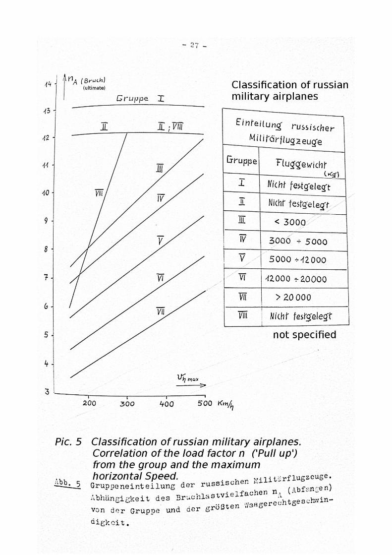


photo detail Pic 10


-48-