Embed Size (px)
Citation preview
0558009994 02/2011
Instruction Manual
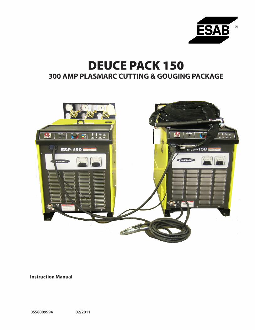
DEUCE PACK 150300 AMP PLASMARC CUTTING & GOUGING PACKAGE
2
II. SPECIFICATIONS
The individual specifications for the ESP-150 are the same as those shown in manual F15-687; however, after they are paralleled, the amended exceptions are as follows:
Total output rating ...................@ 90% Duty Cycle ........................... 300 Amps @ 120VDC ...................................................@ 100% Duty Cycle ......................... 280 Amps @ 120VDCTotal input current ....................@ Rated Load * .................................224 Amps @ 230 VAC ...................................................@ Rated Load* ..................................112 Amps @ 460 VACTotal input current ....................@ Rated Load* .....................................90 Amps @ 575 VACOpen circuit voltage ...........................................................................................370 VDC @ Max.Total weight ........................................................................................................................ .1320 lbs.Gas Requirements (PT-251) ....................................Cutting ........................................ H-35, 90 PSIG (180 SCFH) Gouging ..................................... H-35, 45 PSIG (218 SCFH) (PT-26) .......................................................................................................................See F15-345
* (Note that input fusing & conductors for the individual units remain the same as shown in manual F15-687.)
Note the high open circuit voltage. Use only the torches designed for this equipment. DO NOT attempt to use this equipment with any process other than Plasma Cutting.
I. FEATURES/BENEFITS
The Deuce Pack 150 parallels two ESP-150 consoles and allows an adjustable output current of 25 to 300 amperes. This extended current range capability affords you many desirable features such as:
• cuts up to 4 inch thick carbon steel• cuts up to 3 1/2 inch thick stainless steel and aluminum• removes 56 lbs./hr. gouging carbon steel• removes 76 lbs./hr. gouging stainless steel• uses PT-251 or PT-26 water cooled torch• units can be separated to have two 150 amp systems• convenient 230/460/575 volt, three-phase, 60 hertz
capability
These INSTRUCTIONS are for experienced operators. If you are not fully familiar with the principles of opera-tion and safe practices for arc welding and cutting equipment, we urge you to read our booklet, "Precautions and Safe Practices for Arc Welding, Cutting, and Gouging," Form 52-529. Do NOT permit untrained persons to install, operate, or maintain this equipment. Do NOT attempt to install or operate this equipment until you have read and fully understand these instructions. If you do not fully understand these instructions, contact your supplier for further information. Be sure to read the Safety Precautions before installing or operating this equipment.
BE sUrE this informAtion rEAChEs thE oPErAtor.YoU CAn gEt ExtrA CoPiEs throUgh YoUr sUPPliEr.
USER RESPONSIBILITYThis equipment will perform in conformity with the description thereof contained in this manual and accompanying labels and/or inserts when installed, operated, maintained and repaired in accordance with the instructions provided. This equipment must be checked periodically. Malfunctioning or poorly maintained equipment should not be used. Parts that are broken, missing, worn, distorted or contaminated should be replaced immediately. Should such repair or replacement become necessary, the manufacturer recommends that a telephone or written request for service advice be made to the Authorized Distributor from whom it was purchased.
This equipment or any of its parts should not be altered without the prior written approval of the manufacturer. The user of this equipment shall have the sole responsibility for any malfunction which results from improper use, faulty maintenance, damage, improper repair or alteration by anyone other than the manufacturer or a service facility designated by the manufacturer.
WARNING
CAUTION
3
†Contents Of Spare Parts Kit - P/N 21446
P/N Qty. Description
21442 15 Cutting Tip .093 16980 10 Gouging Tip 21441 3 Electrode (Cutting) 5/32 16979 2 Electrode (Gouging) 5/32 16978 1 Collet 5/32 20070 10 Heat Shield (Long) 20068 1 Long Front Body 61346255 2 Screw 948171 1 Torch Cap Assembly 948179 4 Gasket 86W99 4 O-Ring 14K12 4 O-Ring 950423 2 Rubber Plug 21443 1 Center - Adjust Tool (Cutting) 16985 1 Center - Adjust Tool (Gouging) 2064111 1 Tip Wrench 17672 1 Silicone Lubricant (102) 2064112 1 Hex Screwdriver
For cutting below 200 amp, order Spare Parts Kit 999287.
III. EQUIPMENT SUPPLIED
Deuce Pack 150/PT-251 Cutting/Gouging Package, consist-ing of but not limited to:
P/N Qty. Description
0558002677 2 ESP-150 Console948201 1 PT-251, 70°, 50 ft Torch21446† 1 Spare Parts Kit, 300 Amp Cutting/ Gouging† 998344 1 Regulator R-77-150-580998342 (Note 1) 1 Regulator R-77-150-350 (Note 1)678723 1 Work Cable, 25 ft19414 (Note 1) 1 Fuel Gas Hose, B-FG x B-FG, 25.5 ft 598732 1 Inert Gas Hose B-IG x B-IG, 6 ft.
*Includes 6-ft. paralleling Work Cable
Note 1: Fuel gas hose connects between Regulator (mounted on cylinder) and rear of Primary ESP-150.
Length of Service Lines .........................................................50 ft (15 m)Weight with 50-ft. lines ....................................................19 lbs (8.6 kg)
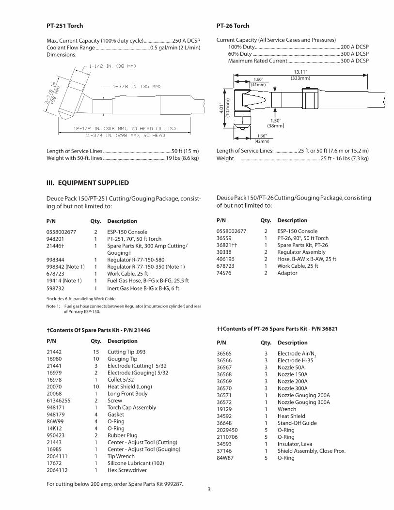
PT-251 Torch
Max. Current Capacity (100% duty cycle) ....................... 250 A DCSPCoolant Flow Range .............................................0.5 gal/min (2 L/min)Dimensions:
Deuce Pack 150/PT-26 Cutting/Gouging Package, consisting of but not limited to:
P/N Qty. Description
0558002677 2 ESP-150 Console36559 1 PT-26, 90°, 50 ft Torch36821†† 1 Spare Parts Kit, PT-2630338 2 Regulator Assembly406196 2 Hose, B-AW x B-AW, 25 ft678723 1 Work Cable, 25 ft 74S76 2 Adaptor
PT-26 Torch
Current Capacity (All Service Gases and Pressures) 100% Duty .......................................................................200 A DCSP 60% Duty .........................................................................300 A DCSP Maximum Rated Current ............................................300 A DCSP
Length of Service Lines: .................. 25 ft or 50 ft (7.6 m or 15.2 m)Weight .................................................................. 25 ft - 16 lbs (7.3 kg)
††Contents of PT-26 Spare Parts Kit - P/N 36821
P/N Qty. Description
36565 3 Electrode Air/N236566 3 Electrode H-3536567 3 Nozzle 50A36568 3 Nozzle 150A36569 3 Nozzle 200A36570 3 Nozzle 300A36571 1 Nozzle Gouging 200A36572 1 Nozzle Gouging 300A19129 1 Wrench34592 1 Heat Shield36648 1 Stand-Off Guide2029450 5 O-Ring2110706 5 O-Ring34593 1 Insulator, Lava37146 1 Shield Assembly, Close Prox.84W87 5 O-Ring
1.60"(41mm)
4.01
"(1
02m
m)
1.50" (38mm)
13.11"(333mm)
1.66" (42mm)
4
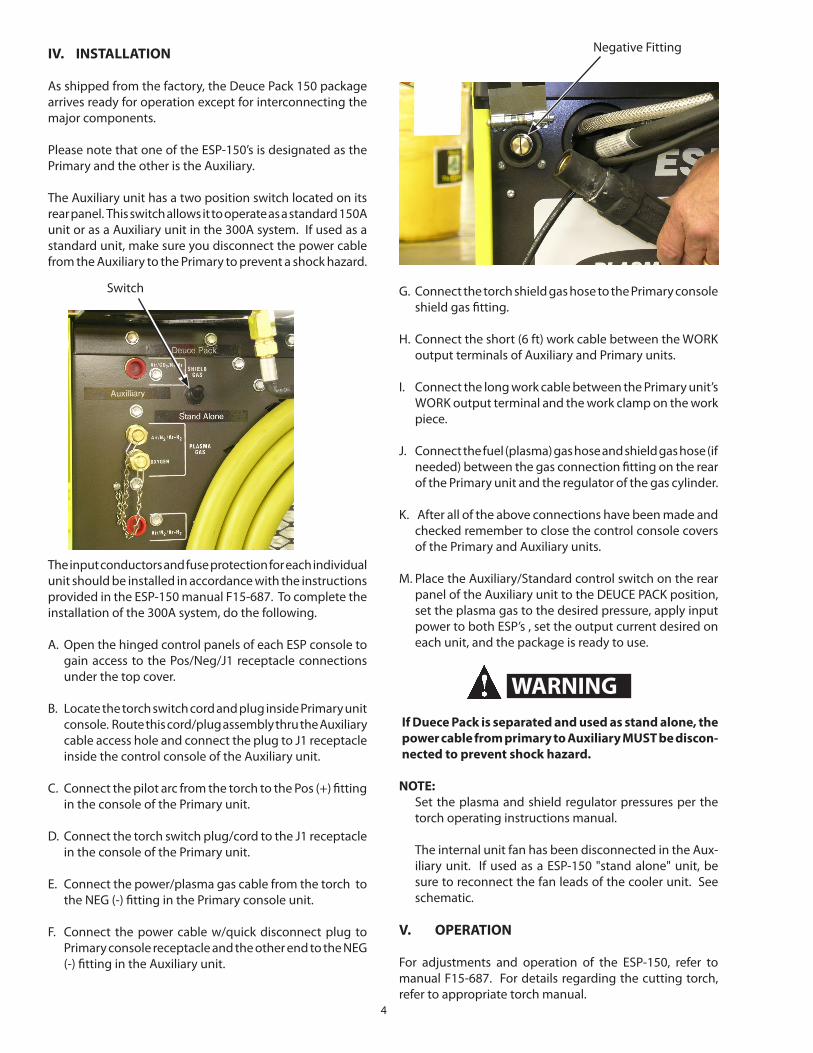
G. Connect the torch shield gas hose to the Primary console shield gas fitting.
H. Connect the short (6 ft) work cable between the WORK output terminals of Auxiliary and Primary units.
I. Connect the long work cable between the Primary unit’s WORK output terminal and the work clamp on the work piece.
J. Connect the fuel (plasma) gas hose and shield gas hose (if needed) between the gas connection fitting on the rear of the Primary unit and the regulator of the gas cylinder.
K. After all of the above connections have been made and checked remember to close the control console covers of the Primary and Auxiliary units.
M. Place the Auxiliary/Standard control switch on the rear panel of the Auxiliary unit to the DEUCE PACK position, set the plasma gas to the desired pressure, apply input power to both ESP’s , set the output current desired on each unit, and the package is ready to use.
If Duece Pack is separated and used as stand alone, the power cable from primary to Auxiliary MUST be discon-nected to prevent shock hazard.
NOTE: Set the plasma and shield regulator pressures per the
torch operating instructions manual.
The internal unit fan has been disconnected in the Aux-iliary unit. If used as a ESP-150 "stand alone" unit, be sure to reconnect the fan leads of the cooler unit. See schematic.
IV. INSTALLATION
As shipped from the factory, the Deuce Pack 150 package arrives ready for operation except for interconnecting the major components.
Please note that one of the ESP-150’s is designated as the Primary and the other is the Auxiliary.
The Auxiliary unit has a two position switch located on its rear panel. This switch allows it to operate as a standard 150A unit or as a Auxiliary unit in the 300A system. If used as a standard unit, make sure you disconnect the power cable from the Auxiliary to the Primary to prevent a shock hazard.
The input conductors and fuse protection for each individual unit should be installed in accordance with the instructions provided in the ESP-150 manual F15-687. To complete the installation of the 300A system, do the following.
A. Open the hinged control panels of each ESP console to gain access to the Pos/Neg/J1 receptacle connections under the top cover.
B. Locate the torch switch cord and plug inside Primary unit console. Route this cord/plug assembly thru the Auxiliary cable access hole and connect the plug to J1 receptacle inside the control console of the Auxiliary unit.
C. Connect the pilot arc from the torch to the Pos (+) fitting in the console of the Primary unit.
D. Connect the torch switch plug/cord to the J1 receptacle in the console of the Primary unit.
E. Connect the power/plasma gas cable from the torch to the NEG (-) fitting in the Primary console unit.
F. Connect the power cable w/quick disconnect plug to Primary console receptacle and the other end to the NEG (-) fitting in the Auxiliary unit.
V. OPERATION
For adjustments and operation of the ESP-150, refer to manual F15-687. For details regarding the cutting torch, refer to appropriate torch manual.
Switch
Negative Fitting
WARNING
5
D-0
5580
0333
5 - O
R
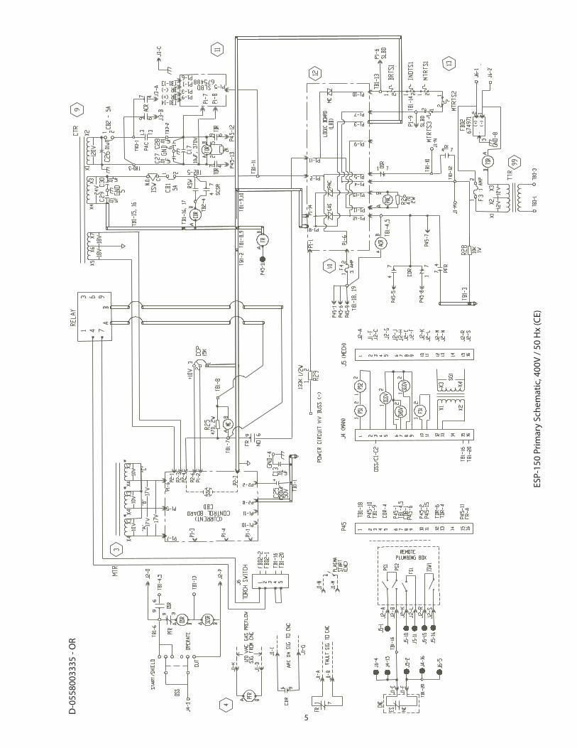
ESP-
150
Prim
ary
Sche
mat
ic, 4
00V
/ 50
Hx
(CE)

6
D-0
5580
0292
6 - D
ESP-
150
Auxi
liary
Sch
emat
ic, 2
30 /
460
/ 575
V
Not
eD
otte
d w
ire m
oved
from
P45
-13
to P
rimar
y / A
uxili
ary
SW-5
.D
isco
nnec
t fan
mot
or o
n Au
xilia
ry u
nit.

7
Manuel d’instructions (FR)
DEUCE PACK 150ENSEMBLE DÉCOUPE ET GOUGEAGE 300 AMP PLASMARC
8
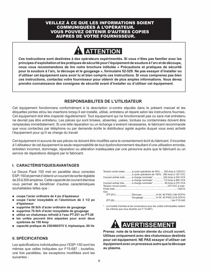
Tension sortie totale ..........à cycle opératoire de 90% ..... 300 Amp à 120VCC ......................................à cycle opératoire de 100% .. 280 Amp à 120 VCCCourant entrée total ...........à charge nominale* ...............224 Amp à 230 VCA ......................................à charge nominale* ............... 112 Amp à 460 VCACourant entrée tota............à charge nominale* .................90 Amp à 575 VCATension circuit ouvert ..............................................................370 VCC à max.Poids total ............................................................................................. 1320 lbGaz (PT-251) ....................... Découpe .....................H-35, 90 PSIG (180 SCFH) Gougeage ...................H-35, 45 PSIG (218 SCFH) (PT-26) .....................................................................................Voir F15-345
* (Le fusible d’entrée et les conducteurs pour les unités individuelles restent les mêmes que ceux illustrés sur F-14-687).
Prenez note de la tension élevée du circuit ouvert. Utilisez uniquement avec des chalumeaux destinés pour cet équipement. NE PAS essayer d’utiliser cet équipement avec un processus autre que la découpe au plasma.
I. CARACTÉRISTIQUES/AVANTAGESLe Deuce Pack 150 met en parallèle deux consoles ESP-150 et permet d’obtenir un courant de sortie réglable de 25 à 300 ampères. Cette capacité de courant étendue vous permet de bénéficier d’autres caractéristiques souhaitables telles que :
coupe l’acier ordinaire de 4 po d’épaisseur coupe l’acier inoxydable et l’aluminium de 3 1/2 po
d’épaisseur supprime 56 lb/h d’acier ordinaire de gougeage supprime 76 lb/h d’acier inoxydable de gougeage utilise un chalumeau refroidi à l’eau PT-251 ou PT-26 les unités peuvent être séparées pour avoir deux
systèmes de 150 Amp capacité pratique de 230/460/575 V, triphasique, 60 Hz
II. SPÉCIFICATIONSLes spécifications individuelles pour l’ESP-150 sont les mêmes que celles indiquées sur F15-687 ; toutefois, une fois parallèles, les exceptions modifiées sont les suivantes :
Ces instructions sont destinées à des opérateurs expérimentés. Si vous n’êtes pas familier avec les principes d’exploitation et les pratiques de sécurité pour l’équipement de soudure à l’arc et de découpe, nous vous recommandons de lire notre brochure intitulée « Précautions et pratiques de sécurité pour la soudure à l’arc, la découpe et le gougeage », formulaire 52-529. Ne pas essayer d’installer ou d’utiliser cet équipement sans avoir lu et bien compris ces instructions. Si vous comprenez pas bien ces instructions, contactez votre fournisseur pour obtenir de plus amples informations. Vous devez prendre connaissance des consignes de sécurité avant d’installer ou d’utiliser cet équipement.
VEILLEZ À CE QUE LES INFORMATIONS SOIENT COMMUNIQUÉES À L’OPÉRATEUR.
VOUS POUVEZ OBTENIR D’AUTRES COPIES AUPRES DE VOTRE FOURNISSEUR.
RESPONSABILITES DE L’UTILISATEURCet équipement fonctionnera conformément à la description ci-contre stipulée dans le présent manuel et les étiquettes jointes et/ou les insertions lorsqu’il est installé, utilisé, entretenu et réparé selon les instructions fournies. Cet équipement doit être inspecté régulièrement. Tout équipement qui ne fonctionnerait pas ou sera mal entretenu ne devrait pas être entretenu. Les pièces qui sont brisées, absentes, usées, tordues ou contaminées doivent être remplacées immédiatement. Si une telle réparation ou un échange s’avèrent nécessaires, le fabricant recommande que vous contactiez par téléphone ou par demande écrite le distributeur agréé auprès duquel vous avez acheté l’équipement pour qu’il se charge du travail.
Cet équipement ni aucune de ses pièces ne doivent être modifiés sans le consentement écrit du fabricant. Il incombe à l’utilisateur de cet équipement la seule responsabilité de tout dysfonctionnement résultant d’une utilisation erronée, entretien incorrect, dommage, réparation ou altération inadéquates par une personne autre que le fabricant ou un service de réparations désigné par le fabricant.
AVERTISSEMENT
ATTENTION
9
†Contenu du kit de pièces de rechange - Réf. 21446
Réf. Qté Description
21442 15 Embout découpe .093 16980 10 Embout gougeage 21441 3 Electrode (découpe) 5/32 16979 2 Electrode (gougeage) 5/32 16978 1 Collete 5/32 20070 10 Écran protecteur (Long) 20068 1 Corps avant long 61346255 2 Vis 948171 1 Cache chalumeau 948179 4 Joint 86W99 4 Joint torique 14K12 4 Joint torique 950423 2 Bouchon caoutchouté 21443 1 Centre - Outil de réglage (découpe) 16985 1 Centre - Outil de réglage (gougeage) 2064111 1 Clé pour pointes 17672 1 Lubrifiant silicone (102) 2064112 1 Tournevis hex
Pour les découpes inférieures à 200 Amp, commandez le kit de pièces de rechange 999287.
III. ÉQUIPEMENT FOURNI
Deuce Pack 150/PT-251 Ensemble Découpe/gougeage comprenant entre autres :
Réf. Qté Description0558002677 2 Console ESP-150948201 1 PT-251, 70Deg. 50 pi Chalumeau21446† 1 Kit de pièces de rechange, 300 Amp Découpe/Gougeage† 998344 1 Régulateur R-77-150-580998342(Remarque 1) 1 Régulateur R-77-150-350 (Remarque 1)678723 1 Câble de travail 25 pi19414(Remarque 1) 1 Tuyau de gaz combustible B-FG x B-FG, 25,5 pi598732 1 Tuyau de gaz inerte B-IG x B-IG, 6 pi
*Inclut un câble de travail en parallèle de 6 pi
Remarque 1 : Tuyau de gaz combustible est connecté entre le régulateur (installé sur le cylindre) et l’arrière de ESP-150 Maître.
Longueur des conduites de service ...................15 m (50 pi)Poids avec conduites de 50 pi ......................... 8,6 kg (19 lb)
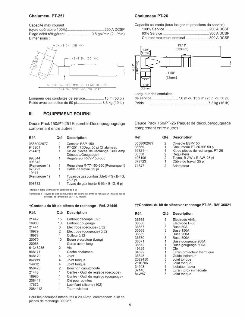
Chalumeau PT-251
Capacité max courant (cycle opératoire 100%).....................................250 A DCSPPlage débit réfrigérant .......................... 0,5 gal/min (2 L/min)Dimensions :
Deuce Pack 150/PT-26 Paquet de découpe/gougeage comprenant entre autres :
Réf. Qté Description0558002677 2 Console ESP-15036559 1 Chalumeau PT-26 90° 50 pi36821†† 1 Kit de pièces de rechange, PT-2630338 2 Régulateur406196 2 Tuyau, B-AW x B-AW, 25 pi678723 1 Câble de travail 25 pi 74S76 2 Adaptateur
Chalumeau PT-26
Capacité courante (tous les gaz et pressions de service) 100% Service ............................................ 200 A DCSP 60% Service .............................................. 300 A DCSP Courant maximum nominal ....................... 300 A DCSP
Longueur des conduites de service ..........................7,6 m ou 15,2 m (25 pi ou 50 pi)Poids ..........................................................7,3 kg (16 lb)
††Contenu du kit de pièces de rechange PT-26 - Réf. 36821
Réf. Qté Description36565 3 Electrode Air/N236566 3 Electrode H-3536567 3 Buse 50A36568 3 Buse 150A36569 3 Buse 200A36570 3 Buse 300A36571 1 Buse gougeage 200A36572 1 Buse gougeage 300A19129 1 Clé34592 1 Écran protecteur thermique36648 1 Guide isolateur2029450 5 Joint torique2110706 5 Joint torique34593 1 Isolateur, Lava37146 1 Écran, prox immédiate84W87 5 Joint torique
1.60"(41mm)
4.01
"(1
02m
m)
1.50" (38mm)
13.11"(333mm)
1.66" (42mm)
10
G. Connectez le tuyau de gaz de l’écran protecteur du chalumeau au raccord de gaz de l’écran protecteur de console maître.
H. Connectez le câble de travail court (6 pi) entre les bornes de sortie WORK des unités esclaves et maîtres.
I. Connectez le long câble de travail entre la borne de sortie WORK de l’unité maître et le clamp de masse sur la pièce de travail.
J. Connectez le tuyau de gaz combustible (plasma) et celui du gaz de l’écran de protection (si besoin) entre le raccord de gaz situé à l’arrière de l’unité maître et le régulateur du cylindre à gaz.
K. Après avoir effectué toutes les connexions ci-dessus et les avoir vérifiées, fermez toujours les couvercles de la console de commande des unités maître et esclaves.
M. Placez l’interrupteur de commande esclave/maître situé sur le panneau arrière de l’unité esclave à la position DEUCE PACK, réglez le gaz plasma à la pression souhaitée, appliquez l’alimentation d’entrée aux deux ESP, réglez le courant de sortie sur toutes les unités et l’ensemble est prêt à l’emploi.
Si Deuce Pack est utilisé en unité autonome, le câble d’alimentation allant du maître à l’esclave DOIT être déconnecté pour éviter tout risque de choc.
REMARQUE : Réglez les pressions du régulateur de l’écran
protecteur et plasma selon le manuel d’instruction d’utilisation du chalumeau.
Le ventilateur de l’unité interne a été déconnecté dans l’unité esclave. Si utilisée comme unité autonome ESP-150, reconnectez toujours les fils du ventilateur de l’unité du refroidisseur. Voir le diagramme schématique.
IV. INSTALLATION
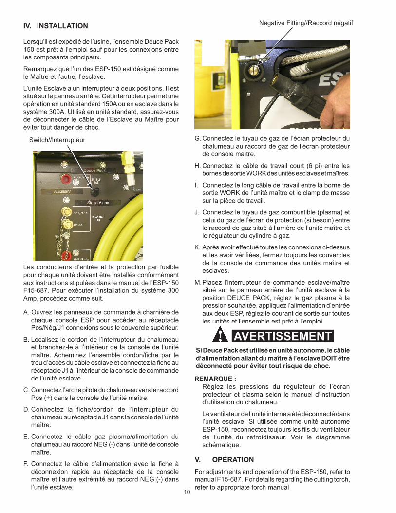
Lorsqu’il est expédié de l’usine, l’ensemble Deuce Pack 150 est prêt à l’emploi sauf pour les connexions entre les composants principaux.
Remarquez que l’un des ESP-150 est désigné comme le Maître et l’autre, l’esclave.
L’unité Esclave a un interrupteur à deux positions. Il est situé sur le panneau arrière. Cet interrupteur permet une opération en unité standard 150A ou en esclave dans le système 300A. Utilisé en unité standard, assurez-vous de déconnecter le câble de l’Esclave au Maître pour éviter tout danger de choc.
Les conducteurs d’entrée et la protection par fusible pour chaque unité doivent être installés conformément aux instructions stipulées dans le manuel de l’ESP-150 F15-687. Pour exécuter l’installation du système 300 Amp, procédez comme suit.
A. Ouvrez les panneaux de commande à charnière de chaque console ESP pour accéder au réceptacle Pos/Nég/J1 connexions sous le couvercle supérieur.
B. Localisez le cordon de l’interrupteur du chalumeau et branchez-le à l’intérieur de la console de l’unité maître. Acheminez l’ensemble cordon/fiche par le trou d’accès du câble esclave et connectez la fiche au réceptacle J1 à l’intérieur de la console de commande de l’unité esclave.
C. Connectez l’arche pilote du chalumeau vers le raccord Pos (+) dans la console de l’unité maître.
D. Connectez la fiche/cordon de l’interrupteur du chalumeau au réceptacle J1 dans la console de l’unité maître.
E. Connectez le câble gaz plasma/alimentation du chalumeau au raccord NEG (-) dans l’unité de console maître.
F. Connectez le câble d’alimentation avec la fiche à déconnexion rapide au réceptacle de la console maître et l’autre extrémité au raccord NEG (-) dans l’unité esclave.
V. OPÉRATION For adjustments and operation of the ESP-150, refer to manual F15-687. For details regarding the cutting torch, refer to appropriate torch manual
Switch//Interrupteur
Negative Fitting//Raccord négatif
AVERTISSEMENT

11
D-0
5580
0333
5 - O
R
Dia
gram
me
sché
mat
ique
maî
tre E
SP
-150
, 400
V /
50 H
x (C
E)
12
D-0
5580
0292
6 - D
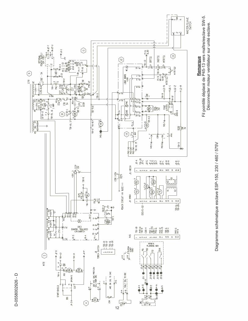
Dia
gram
me
sché
mat
ique
esc
lave
ES
P-1
50, 2
30 /
460
/ 575
V
Rem
arqu
eFi
l poi
ntill
é dé
plac
é de
P45
-13
vers
maî
tre/e
scla
ve S
W-5
.D
écon
nect
er m
oteu
r ven
tilat
eur s
ur u
nité
esc
lave
.

13
REVISION hISTORY
1. 02/2011 - New manual created from 0558004147 with updated pics.
A. CUSTOMER SERVICE QUESTIONS: Telephone: (800)362-7080 / Fax: (800) 634-7548 Hours: 8:00 AM to 7:00 PM EST Order Entry Product Availability Pricing Order Information Returns
B. ENGINEERING SERVICE: Telephone: (843) 664-4416 / Fax : (800) 446-5693 Hours: 7:30 AM to 5:00 PM EST Warranty Returns Authorized Repair Stations Welding Equipment Troubleshooting
C. TECHNICAL SERVICE: Telephone: (800) ESAB-123/ Fax: (843) 664-4452 Hours: 8:00 AM to 5:00 PM EST Part Numbers Technical Applications Specifications Equipment Recommendations
D. LITERATURE REQUESTS: Telephone: (843) 664-5562 / Fax: (843) 664-5548 Hours: 7:30 AM to 4:00 PM EST
E. WELDING EQUIPMENT REPAIRS: Telephone: (843) 664-4487 / Fax: (843) 664-5557 Hours: 7:30 AM to 3:30 PM EST Repair Estimates Repair Status
F. WELDING EQUIPMENT TRAINING Telephone: (843)664-4428 / Fax: (843) 679-5864 Hours: 7:30 AM to 4:00 PM EST Training School Information and Registrations
G. WELDING PROCESS ASSISTANCE: Telephone: (800) ESAB-123 Hours: 7:30 AM to 4:00 PM EST
H. TECHNICAL ASST. CONSUMABLES: Telephone : (800) 933-7070 Hours: 7:30 AM to 5:00 PM EST
IF YOU DO NOT KNOW WhOM TO CALL
Telephone: (800) ESAB-123 Fax: (843) 664-4462
Hours: 7:30 AM to 5:00 PM ESTor
visit us on the web at http://www.esabna.comThe ESAB web site offers
Comprehensive Product InformationMaterial Safety Data Sheets
Warranty RegistrationInstruction Literature Download Library
Distributor LocatorGlobal Company Information
Press ReleasesCustomer Feedback & Support
ESAB Welding & Cutting Products, Florence, SCCOMMUNICATION GUIDE - CUSTOMER SERVICES