Embed Size (px)
Citation preview
This document is downloaded from DR‑NTU (https://dr.ntu.edu.sg)Nanyang Technological University, Singapore.
Deterministic and reliability assessment of basalheave stability for braced excavations with jetgrout base slab
Goh, Anthony Teck Chee
2017
Goh, A. T. C. (2017). Deterministic and reliability assessment of basal heave stability forbraced excavations with jet grout base slab. Engineering Geology, 218, 63‑69.
https://hdl.handle.net/10356/86642
https://doi.org/10.1016/j.enggeo.2016.12.017
© 2017 Elsevier B.V. This is the author created version of a work that has been peerreviewed and accepted for publication by Engineering Geology, Elsevier B.V. It incorporatesreferee’s comments but changes resulting from the publishing process, such ascopyediting, structural formatting, may not be reflected in this document. The publishedversion is available at: [http://dx.doi.org/10.1016/j.enggeo.2016.12.017].
Downloaded on 07 Feb 2022 20:06:49 SGT
1
Deterministic and reliability assessment of basal heave stability for braced excavations with jet grout base slab
A. T. C. Goh1
Abstract: For braced excavations in deep deposits of soft clays, it is common to construct a
jet grout slab (JGP) beneath the excavation in order to restrain the wall deformation, reduce
the forces acting on the struts and to increase the basal heave factor of safety. In this paper,
finite element analyses were carried out to assess the basal heave factor of safety for
excavations in soft clays supported by JGP. The finite element analyses indicate that the
interface friction between the jet grout slab and the wall is a key component contributing to
the resistance of the excavation system to basal heave failure. Comparison of the factor of
safety from the finite element analyses with limit equilibrium predictions based on the slip
circle method and the modified Terzaghi method were then performed. Since the
conventional factor of safety approach does not explicitly reflect the uncertainties of the soil
and JGP properties, and the excavation geometry on the excavation system performance, a
series of reliability analyses were also carried out to assess the basal heave factor of safety for
excavations supported by JGP. The provided spreadsheet template can be used to estimate the
probability of basal heave failure for deep excavations supported by jet grout slabs.
KEY WORDS: basal heave; braced excavation; clay; factor of safety; jet grout pile;
structural reliability.
1Associate Professor, School of Civil & Environmental Engrg., Nanyang Technological
University, Nanyang Avenue, Singapore 639798. E-mail: [email protected]
2
1. Introduction
Deep excavations in soft clays often result in excessive wall and ground movements which
may cause damage to adjacent buildings and utilities. These movements can still be
significant even with the use of stiff retaining walls systems such as diaphragm walls and
secant bored piles and multiple levels of struts. One possible solution to minimize movements
is to use concrete cross walls or buttress walls (Ou et al. 2006). Another possible solution is
to use a ground improvement technique known as jet grouting prior to excavation (Wen 2005;
Ou 2006). The jet grouting process produces a series of short overlapping grout columns to
produce a “continuous” base slab (commonly termed as jet grout pile or JGP) below the final
excavation level that spans across the entire excavation (Gaba 1990; Hsieh et al. 2003; Ho
and Hu 2006). Typically, the JGP thickness ranges from 2 m to 4 m. In one particular large
excavation (approximately 90 m wide and 240 m long) in Singapore, a 9 m thick JGP slab
was used (Wong and Poh 2000). Generally, the JGP is designed to prevent basal heave
instability (Shirlaw 2003), restrain the wall deformations and provide lateral support to
reduce the forces acting on the struts. For example, the study by Hsieh et al. (2003) indicated
reduction in the wall deformation by as much as 40% with the installation of a jet grout slab.
The focus of this paper is on the assessment of basal heave instability for deep excavations in
clay with JGP. Comparative deterministic calculations of the basal heave factor of safety
have been performed using limit equilibrium methods and nonlinear finite element analyses.
Since the conventional factor of safety approach does not explicitly reflect the uncertainties
of the soil and JGP properties, and the excavation geometry on the excavation system
performance, it is demonstrated in this paper that a reliability based approach in a spreadsheet
environment can be used to assess the probability of basal heave failure. Example
applications of the use of probabilistic approaches in the design of braced excavations include

3
Goh and Kulhawy (2005), Park et al. (2007), Wu et al. (2010) and Luo et al. (2012).
2. Limit Equilibrium Method
The Terzaghi (1943), Bjerrum and Eide (1956) and Eide et al. (1972) methods which are
based on bearing capacity theory are commonly used to assess basal heave stability for
conventional excavations in clays. Another method that is commonly adopted in Japan and
Taiwan is the slip circle method which involves taking moments about the lowest strut level
(JSA 1988; Hsieh et al. 2008; Luo et al. 2012). The slip circle method has also been applied
for excavations with a JGP at the base by incorporating the undrained shear strength of the
JGP. In the slip circle method, the basal heave factor of safety FSslip is assessed by taking
moments about the lowest strut level (Fig. 1)
)2/R(q)2/R(WdcRdcR
MMFS 2
2/
0 0 uJu
d
rslip +
ω+ω== ∫ ∫
π+θ β
(1)
where Mr = resisting moment; Md = driving moment; R = radius of the failure slip circle; W =
weight of the soil mass behind the wall and above the excavation level; q = surcharge
pressure; H = excavation depth; D = wall penetration depth; B = excavation width; cu = clay
undrained shear strength; cuJ = JGP undrained shear strength; θ and β = angles shown in Fig.
1.
Fig. 1. Slip circle method for basal heave stability of jet grout pile
For comparison, another limit equilibrium method called the modified Terzaghi method
(Wong and Goh 2002; Goh et al. 2008) is used to assess the basal heave factor of safety for
excavations involving a JGP layer. In this method, the effects of the JGP is considered by
4
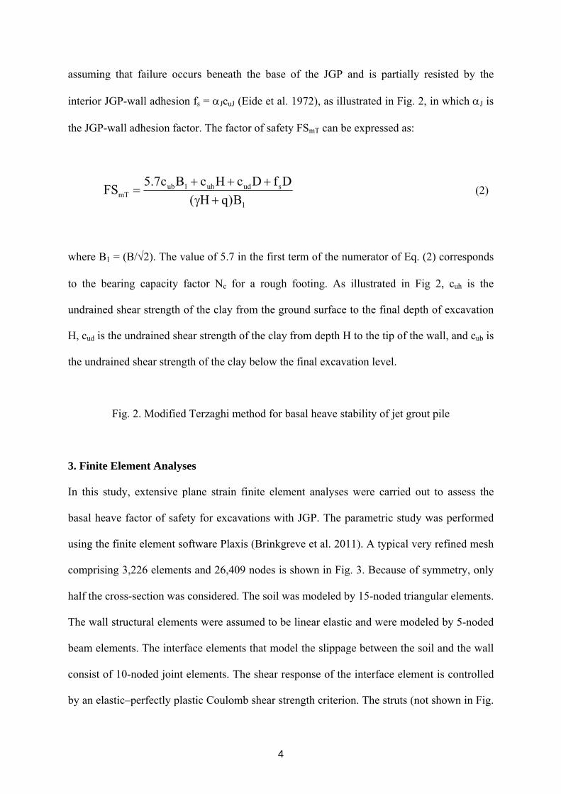
assuming that failure occurs beneath the base of the JGP and is partially resisted by the
interior JGP-wall adhesion fs = αJcuJ (Eide et al. 1972), as illustrated in Fig. 2, in which αJ is
the JGP-wall adhesion factor. The factor of safety FSmT can be expressed as:
1
suduh1ubmT B)qH(
DfDcHcBc7.5FS+γ
+++= (2)
where B1 = (B/√2). The value of 5.7 in the first term of the numerator of Eq. (2) corresponds
to the bearing capacity factor Nc for a rough footing. As illustrated in Fig 2, cuh is the
undrained shear strength of the clay from the ground surface to the final depth of excavation
H, cud is the undrained shear strength of the clay from depth H to the tip of the wall, and cub is
the undrained shear strength of the clay below the final excavation level.
Fig. 2. Modified Terzaghi method for basal heave stability of jet grout pile
3. Finite Element Analyses
In this study, extensive plane strain finite element analyses were carried out to assess the
basal heave factor of safety for excavations with JGP. The parametric study was performed
using the finite element software Plaxis (Brinkgreve et al. 2011). A typical very refined mesh
comprising 3,226 elements and 26,409 nodes is shown in Fig. 3. Because of symmetry, only
half the cross-section was considered. The soil was modeled by 15-noded triangular elements.
The wall structural elements were assumed to be linear elastic and were modeled by 5-noded
beam elements. The interface elements that model the slippage between the soil and the wall
consist of 10-noded joint elements. The shear response of the interface element is controlled
by an elastic–perfectly plastic Coulomb shear strength criterion. The struts (not shown in Fig.
5
3) were modeled by linear elastic 3-noded bar elements. The nodes along the side boundaries
of the mesh were constrained from displacing horizontally while the nodes along the bottom
boundary were constrained from moving horizontally and vertically. The right vertical
boundary extends far from the excavation (~5B) to minimize the effects of the boundary
restraints.
The Hardening Soil (HS) constitutive relationship was used to model the undrained behavior
of the clay and the JGP. The HS model is an elastic-plastic soil model based on the classical
plasticity theory (Schanz et al. 1999; Brinkgreve et al. 2011) for simulating the behavior of
soils. The model involves frictional hardening characteristics to model plastic shear strain in
deviatoric loading, and cap hardening to model plastic volumetric strain in primary
compression. Failure is defined by the Mohr Coulomb failure criterion. The main input
parameters are E50ref, a reference secant modulus corresponding to the reference confining
pressure pref, a power m for stress-dependent stiffness formulation, friction angle φ, cohesion
c, failure ratio Rf, Eurref the reference stiffness modulus for unloading and reloading
corresponding to pref, and υur the unloading and reloading Poisson’s ratio. This model has
been used successfully for analyses of deep excavations by a number of researchers in
Singapore (Teo and Wong 2012) and elsewhere (Finno et al. 2007; Bryson and Zapata-
Medina 2012; Surarak et al. 2012). For this study, only cases with a homogeneous clay layer
with constant undrained shear strength cu were considered. The soil is assumed to be
subjected to undrained shearing during excavation. Only clays with isotropic cu are
considered. The depth to the hard stratum is assumed to be large. The properties of the JGP
(see Table 1) are based on common design values used in Singapore (Ho and Hu 2006). In
addition, it is assumed that the wall has enough capacity not to fail under the action of deep-
seated soil movements.
6
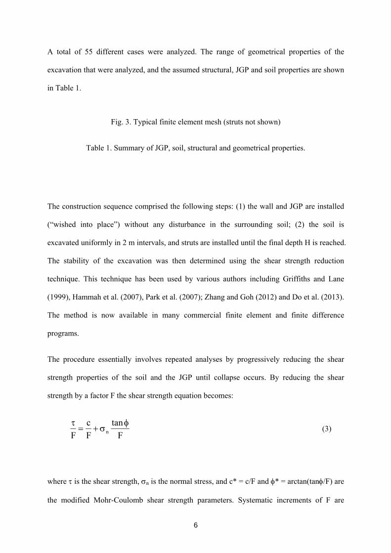
A total of 55 different cases were analyzed. The range of geometrical properties of the
excavation that were analyzed, and the assumed structural, JGP and soil properties are shown
in Table 1.
Fig. 3. Typical finite element mesh (struts not shown)
Table 1. Summary of JGP, soil, structural and geometrical properties.
The construction sequence comprised the following steps: (1) the wall and JGP are installed
(“wished into place”) without any disturbance in the surrounding soil; (2) the soil is
excavated uniformly in 2 m intervals, and struts are installed until the final depth H is reached.
The stability of the excavation was then determined using the shear strength reduction
technique. This technique has been used by various authors including Griffiths and Lane
(1999), Hammah et al. (2007), Park et al. (2007); Zhang and Goh (2012) and Do et al. (2013).
The method is now available in many commercial finite element and finite difference
programs.
The procedure essentially involves repeated analyses by progressively reducing the shear
strength properties of the soil and the JGP until collapse occurs. By reducing the shear
strength by a factor F the shear strength equation becomes:
F
tanFc
F nφ
σ+=τ
(3)
where τ is the shear strength, σn is the normal stress, and c* = c/F and φ* = arctan(tanφ/F) are
the modified Mohr-Coulomb shear strength parameters. Systematic increments of F are
7
performed until the finite element model does not converge to a solution (i.e. failure occurs).
The critical strength reduction value which corresponds to non-convergence is taken to be the
basal heave factor of safety FSFE.
4. Finite Element Results
For brevity, only some general trends of the finite element analyses are highlighted. The
influence of the width of the excavation B are shown in Figs. 4 and 5 for two different
excavation depths H = 16 m and H = 24 m, respectively. The basal heave factor of safety
FSFE decreases with the increase of the excavation width. Comparing the factor of safety with
and without the JGP, the increase in FSFE with the JGP is more significant for B ≤ 20 m. For
example, for the case with B = 20 m and H = 16 m, the installation of a 4 m thick JGP
increased the basal heave factor of safety by 31% compared with a 16% increase for B = 30
m.
Fig. 6 shows the influence of the JGP-wall adhesion factor αJ on the factor of safety. The
factor of safety reduces significantly for αJ ≤ 0.67. For example, for the case with B = 20 m
and H = 16 m, the installation of the JGP increased the FSFE by 31% for αJ = 1, compared
with an increase of 17% for αJ = 0.5. The results highlight that the interface friction between
the jet grout slab and the wall is a key component of the resistance of the excavation system
to basal heave failure. As expected, the factor of safety increases with increased thickness of
the JGP as shown in Fig. 7.
Fig. 4. Effects of excavation width B on FSFE (H = 16 m and cu = 50 kPa)
Fig. 5. Effects of excavation width B on FSFE (H = 24 m and cu = 80 kPa)
8
Fig. 6. Effects of JGP-wall interface adhesion factor on FSFE (B = 20 m, H = 16 m, D = 4 m
and cu = 50 kPa)
Fig. 7. Effects of JGP thickness on FSFE (B = 20 m, H = 16 m, and cu = 50 kPa)
Comparison of the FSFE values with the predictions based on the slip circle method (FSslip)
and the modified Terzaghi method (FSmT) are shown in Fig. 8. Generally, there is more
scatter in the FSslip predictions using the slip circle method compared with the predictions
using FSmT. The modified Terzaghi method generally predicts reasonable values of the basal
heave factor of safety FSmT compared with FSFE. In this study, only clays with constant cu
were considered. In the previous study by Wong & Goh (2002), it was found that for clays
with cu increasing linearly with depth, both the Terzaghi method and modified Terzaghi
method were found to give good estimations of the factor of safety (compared with the finite
element results) if the average cu values were used. For example, the cuh value is taken as the
average cu from the ground surface to the depth H, and the cub value is taken as the average cu
from depth H to depth (H + B1). The same approach was found to work in applying the
modified Terzaghi equation (Eq. 2) to cases of JGP stabilized soil. For brevity, the results
have been omitted in this paper.
Fig. 8. Comparison of FSFE versus FS predicted using slip circle (FSslip) and modified
Terzaghi (FSmT) methods
9
5. Reliability Analyses
Since the deterministic factor of safety approach outlined in the previous section does not
explicitly reflect the uncertainties of the soil and JGP properties, and the excavation geometry
on the excavation system performance, a reliability based approach is proposed in this section
to assess the probability of basal heave failure.
In the conventional deterministic evaluation of geotechnical stability, the factor of safety is
defined as the ratio of the resistance R to the load (stress) S. In the reliability approach, the
boundary separating the safe and failure domain is the limit state surface (boundary) defined
as:
G(x) = R – S = 0 (4)
where x denotes the vector of the random variables. Mathematically, R > S or G(x) > 0 would
denote a ‘safe’ domain, and R < S or G(x) < 0 would denote a ‘failure’ domain. The
calculation of the probability of failure Pf involves the integration of the probability density
function (pdf) over the failure domain.
One method to quantify the probability of failure is to carry out Monte Carlo simulations
using random variables with specified joint probability distributions to represent the
geotechnical uncertainties and to perform a large number of deterministic analyses. Clear
expositions of the reliability approach are found in various publications (Ang and Tang 1984;
Melchers 1987; Baecher and Christian 2003). A well-developed approximate alternative is to
use the First-Order Reliability Method (FORM) proposed by Hasofer and Lind (1974). Its
popularity results from the mathematical simplicity, since only second moment information
10
(mean and standard deviation) on the random variables is required to calculate the reliability
index β. Mathematically, β can be computed as
⎟⎟⎠
⎞⎜⎜⎝
⎛σ
μ−⎟⎟⎠
⎞⎜⎜⎝
⎛σ
μ−=β −
∈i
ii1T
i
ii
Fx
x]R[xmin (5)
in which xi is the set of n random variables, μi is the set of mean values, R is the correlation
matrix and F is the failure region. The minimization in Eq. (5) is performed over F
corresponding to the region G(x) = 0. Low (2005) had shown that a spreadsheet environment
can be used to perform the minimization and determine β. The probability of failure is
inferred from the reliability index as
Pf ≈ Φ(-β) (6)
in which Φ(-β) is the value of the cumulative probability. Examples of the use of reliability to
assess basal heave stability in conventional excavations can be found in Park et al. (2007),
Goh et al. (2008), and Wu et al. (2010).
In this paper, the spreadsheet solution implementing the first order reliability method FORM
for basal heave stability using the modified Terzaghi method to determine the factor of safety
FS (Goh et al. 2008) has been adopted taking into consideration the JGP-wall interface
adhesion fs. In a previous study (Goh et al. 2008), in which basal heave reliability analyses
were considered for Terzaghi’s method, modified Terzaghi’s method, Bjerrum & Eide
method, and Eide’s method, the main properties influencing the probability of failure were
found to be the soil unit weight and soil undrained shear strength and their COV. The
11
uncertainties (COV) in the geometrical properties of the excavation system were found to
have minimal influence on the probability of failure. As an illustration, in this paper, only the
uncertainties in the surcharge, soil and JGP parameters, and H and D were considered. Fig. 9
shows an example setup of the spreadsheet for evaluating the reliability index for the
modified Terzaghi expression in Eq. (2). There are eight lognormally distributed and
uncorrelated variables: cub, cuh, q, γ, H, cud, fs and D. The width of the excavation B is
assumed to be constant. The uncertainties in the parameters H and D could arise from
construction deviations in the actual excavation depth and depth of wall penetration,
respectively. Detailed explanations of the spreadsheet setup can be found in Goh et al. (2008).
Initially, the x values of the variables (cells C5 to C12) are set to the mean values (cells D6 to
D12). For evaluating the probability of failure, the design safety level FSlimit (cell O29) is set
to unity. The reliability index β and the probability of failure Pf are calculated in cell D32 and
cell E32, respectively. The Solver spreadsheet function is invoked to minimize β by changing
the x values (cells C5 to C12) subject to G(x) = FS – FSlimit = 0 (cell O32).
Fig. 9. Spreadsheet setup for reliability analysis
Since a comparison on the factor of safety based on the modified Terzaghi method (in section
4) was found to be in good agreement with the finite element results, it has been assumed that
the model error (imperfection of the prediction model) is minimal compared with the other
random variables. If the model error is significant, one or more random variable correction
factors can be incorporated into the limit state surface equation as described in Ang and Tang
(1984). In this paper, the uncertainties (inherent variability) of the soil and JGP are limited to
the coefficient of variation (COV: standard deviation divided by the mean) of the
12
geotechnical properties. As there is only sparse published data on the spatial variability (and
also inherent variability) of the JGP geotechnical properties, the spatial variability
(Vanmarcke, 1977) is not addressed in this paper.
This section presents the results of analyses to assess the probability of failure Pf (FS ≤ 1) for
excavations in clays with FSmean values ranging from 1.2 to 1.7, where FSmean is the factor of
safety computed using the mean values of the parameters. In all the analyses, the mean and
COV of the surcharge adjacent to the excavation q and the unit weight of the clay γ are
assumed to be unchanged (meanq = 10 kPa/m, COVq = 0.2; meanγ = 16 kN/m3, COVγ =
0.15). Based on the database by Phoon and Kulhawy (1999) the inherent variability of the
undrained shear strength of clay is 0.3. Hence, for the majority of the analyses, the COVs of
the soil undrained shear strength (for simplicity, the term COVcu is used) was assumed to be
0.3. Some analyses were also carried out for COVcu = 0.2.
The results of a series of analyses for FSmean values ranging from 1.2 to 1.7 for COVcu = 0.3
and COVcu = 0.2 are shown in Table 2 and Fig. 10. The FSmean is calculated based on Eq. (2).
The results highlight the significant influence of the COVfs of the JGP-wall adhesion on the
probability of failure Pf as the COV of fs is increased from 0.1 to 0.6. As expected, for a given
FSmean, the probability of failure Pf increases as the COVfs increases. For example, for FSmean
= 1.5, Pf increased 41% as the COVfs increases from 0.1 to 0.4. For FSmean = 1.5 and COVfs =
0.6, the probability of basal heave failure is still fairly high (9.1%). The same trends are
observed for cases with COVcu = 0.2. The results highlight the influence of the COVcu on the
probability of failure. For example, with a reduction in the COVcu from 0.3 to 0.2, for FSmean
= 1.5 and COVfs = 0.6, the probability of basal heave failure is reduced from 9.1% to 4.6%.
The above results show that the same factor of safety can have vastly different levels of risk
13
depending on the degree of uncertainty of COVcu and COVfs. The proposed reliability
approach provides a systematic method for evaluating the influences of the uncertainties in
the various parameters affecting FSmean and to assist design engineers assess the acceptable
level of risk.
Table 2. Probability of failure for COVcu = 0.2 and COVcu = 0.3
Fig. 10. Plot of Pf for various COVcu and COVfs
6. Summary
Finite element analyses were carried out to assess the basal heave factor of safety for
excavations in soft clays supported by JGP. A total of 55 different cases with different
geometrical properties of the excavation, JGP and soil properties were considered. The basal
heave factor of safety FSFE was found to decrease with the increase of the excavation width.
Comparing the factor of safety with and without the JGP, the increase in FSFE with the JGP is
more significant for B ≤ 20 m. The finite element analyses also highlight that the interface
friction between the jet grout slab and the wall is a key component of the resistance of the
excavation system to basal heave failure.
Comparison of the FSFE values with the predictions based on the slip circle method and the
modified Terzaghi method was also performed. Generally, there is more scatter in the FSslip
predictions using the slip circle method compared with the predictions using FSmT. The
modified Terzaghi method generally predicts reasonable values of the basal heave factor of
safety FSmT compared with FSFE.
14
A series of reliability analyses were then carried out to assess the basal heave factor of safety
for excavations supported by JGP. The results show that the same factor of safety can have
vastly different levels of risk depending on the degree of uncertainty of the design
parameters. For example, for FSmean = 1.5 and COVcu = 0.3, the Pf is approximately 5% for
COVfs = 0.1. The Pf increases to approximately 9% for COVfs = 0.6. The provided
spreadsheet template can be used to estimate the probability of basal heave failure for deep
excavations supported by jet grout slabs. The reliability approach provides a systematic
method for evaluating the influences of the uncertainties in the various parameters affecting
FSmean and can be used to assist design engineers assess the acceptable level of risk. In this
paper, the uncertainties (inherent variability) of the soil and JGP are limited to the coefficient
of variation of the geotechnical properties. As there is only sparse published data on the
spatial variability of the JGP geotechnical properties, the spatial variability is not addressed in
this paper.
References
Ang, A.H.S., Tang, W.H., 1984. Probability concepts in engineering planning and design.
Vol. II - Decision, risk and reliability. John Wiley & Sons, New York.
Baecher, G.B., Christian, J.T., 2003. Reliability and statistics in geotechnical engineering.
John Wiley & Sons, New York.
Bjerrum, L., Eide, O., 1956. Stability of strutted excavations in clay. Geotechnique. 6(1), 32-
47.
Brinkgreve, L.B.J., Engin, E., Swolfs, W.M., 2011. Plaxis user manual, PLAXIS bv,
Netherlands.
Bryson, L., Zapata-Medina, D., 2012. Method for estimating system stiffness for excavation
support walls. J. Geotech. Geoenviron. Eng. ASCE 138 (9), 1104-1115.
15
Do, T., Ou, C. ., Lim, A., 2013. Evaluation of factors of safety against basal heave for deep
excavations in soft clay using the finite-element method. J. Geotech. Geoenviron. Eng. ASCE
139 (12), 2125-2135.
Eide, O., Aas, G., Josang, T., 1972. Special applications of cast-in-place walls for tunnels in
soft clay in Oslo. Pub. 91, Norwegian Geotechnical Institute, Oslo, 63-72.
Finno, R.J., Blackburn, J.T., Roboski, J. F., 2007. Three-dimensional effects for supported
excavations in clay. J. Geotech. Geoenviron. Eng. ASCE 133 (1), 30-36.
Gaba, A.R., 1990. Jet grouting at Newton Station, Singapore. Proc. 10th Southeast Asian
Geotech Conf., Taipei, Taiwan, SEAGC, 77-79.
Goh, A.T.C., Kulhawy, F.H., 2005. Reliability assessment of serviceability performance of
braced retaining walls using a neural network approach. Int. J. Num. Analy. Meth. Geomech.
29 (6), 627-642.
Goh, A.T.C, Kulhawy, F.H., Wong, K.S., 2008. Reliability assessment of basal-heave
stability for braced excavations in clay. J. Geotech. Geoenviron. Eng. ASCE 134 (2), 145-
153.
Griffiths, D.V., Lane, P.A., 1999. Slope stability analysis by finite elements. Géotechnique
49 (3), 387-403.
Hammah, R.E., Yacoub, T., Curran, J.H., 2007. Serviceability-based slope factor of safety
using the shear strength reduction (SSR) method. The Second Half Century of Rock
Mechanics 11th Congress of the International Society for Rock Mechanics, Taylor & Francis,
1137-1140.
Hasofer, A.M., Lind, N.C., 1974. An exact and invariant first-order reliability format. J. Eng.
Mech., ASCE 100 (1), 111-121.
16
Ho, C.E., Hu, S., 2006. Numerical analysis of jet grout elements for braced excavation in soft
clay. Proc. ASCE GeoCongress 2006: Geotechnical Engineering in the Information
Technology Age, Atlanta, Georgia. 1-6.
Hsieh. H.S., Wang, C.C., Ou, C.Y., 2003. Use of jet grouting to limit diaphragm wall
displacement of a deep excavation. J. Geotech. Geoenviron. Eng. ASCE 129 (2), 146-157.
Hsieh. P.G., Ou, C.Y., Liu H.T., 2008. Basal heave analyses of excavations with
consideration of anisotropic undrained strength of clay. Can. Geotech. J. 45, 788-799.
JSA, 1988. Guidelines of design and construction of deep excavations. Japanese Society of
Architecture, Tokyo, Japan.
Low, B.K., 2005. Reliability-based design applied to retaining walls. Geotechnique 55 (1),
63-75.
Luo, Z., Atamturktur, S, Cai, Y, Juang, C.H., 2012. Reliability analysis of basal-heave in a
braced excavation in a 2-D random field. Comp. Geot. 39, 27-37.
Melchers, R.E., 1987. Structural reliability: Analysis and prediction. Ellis Horwood Ltd.,
Chichester, England.
Ou, C.Y., 2006. Deep Excavation: Theory and Practice. Taylor & Francis Group, London.
Ou, C.Y., Lin, Y.L., Hsieh, P.G., 2006. Case record of an excavation with cross walls and
buttress walls. Journal of GeoEng. 1 (2), 79-86.
Park, J.K., Blackburn, J.T., Gardoni, P., 2007 Reliability assessment of excavation systems
considering both stability and serviceability performance. Georisk 1 (3), 123-141.
Phoon, K.K., Kulhawy, F.H., 1999. Characterization of geotechnical variability. Can. Geot. J.
36 (4), 612-624.
17
Schanz, T., Vermeer, P.A., Bonnier, P.G., 1999. The hardeing soil model -formulation and
verification. Proc., Beyond 2000 in Computational Geotechnics-10 years PLAXIS, Balkema,
Rotterdam, 281-296.
Shirlaw, J.N., 2003. Jet grouting soft clays for tunneling and deep excavations – design and
construction issues. Proc. 3rd Int. Conf., Grouting and Grout Treatment, ASCE 1, 257-268.
Surarak, C., Likitlersuang, S., Wanatowski, D., Balasubramaniam, A., Oh, E., Guan, H.,
2012. Stiffness and strength parameters for hardening soil model of soft and stiff Bangkok
clays. Soils Found. 52 (4), 682–697
Terzaghi, K., 1943. Theoretical soil mechanics. John Wiley & Sons, New York.
Teo, P.L., Wong, K.S., 2012. Application of the Hardening Soil model in deep excavation
analysis. The IES Journal Part A: Civil & Struct. Eng. 5 (3), 152-165.
Vanmarcke, E.H., 1977. Probabilistic modeling of soil profiles. J. Geotech. Eng. ASCE 103
(11), 1227-1246.
Wen, D., 2005. Use of jet grouting in deep excavations. In Ground improvement – case
histories. Editors: B. Indraratna & J. Chu. Elsevier. 357-370.
Wong I.H., Poh, T.Y., 2000. Effects of jet grouting on adjacent ground and structures. J.
Geotech. Geoenviron. Eng. ASCE 126 (3), 247-256.
Wong, K.S., Goh, A.T.C., 2002. Basal heave stability for wide excavations. Proc. 3rd Int.
Symp. Geotech. Aspects of Underground Construction in Soft Ground, Toulouse, 699-704.
Wu, S.H., Ou, C.Y., Ching, J., Juang, C.H., 2012. Reliability-based design for basal heave
stability of deep excavations in spatially varying soils, J. Geotech. Geoenviron. Eng. ASCE 138
(5), 594-603.
18
Zhang, W.G., Goh, A.T.C., 2012. Reliability assessment on ultimate and serviceability limit
states and determination of critical factor of safety for underground rock caverns. Tunnel
Underg. Space Technol. 32, 221–230.
19
LIST OF TABLES
Table 1. Summary of JGP, soil, structural and geometrical properties
Table 2. Probability of failure for COVcu = 0.2 and COVcu = 0.3
20
LIST OF FIGURES
Fig. 1. Slip circle method for basal heave stability of excavation with jet grout pile
Fig. 2. Modified Terzaghi method for basal heave stability of excavation with jet grout pile
Fig. 3. Typical finite element mesh (struts not shown)
Fig. 4. Effects of excavation width B on FSFE (H = 16 m and cu = 50 kPa)
Fig. 5. Effects of excavation width B on FSFE (H = 24 m and cu = 80 kPa)
Fig. 6. Effects of JGP-wall interface adhesion factor on FSFE (B = 20 m, H = 16 m, D = 4 m
and cu = 50 kPa)
Fig. 7. Effects of JGP thickness on FSFE (B = 20 m, H = 16 m and cu = 50 kPa)
Fig. 8. Comparison of FSFE versus FS predicted using slip circle (FSslip) and modified
Terzaghi (FSmT) methods
Fig. 9. Spreadsheet setup for reliability analysis
Fig. 10. Plot of Pf for various COVcu and COVfs
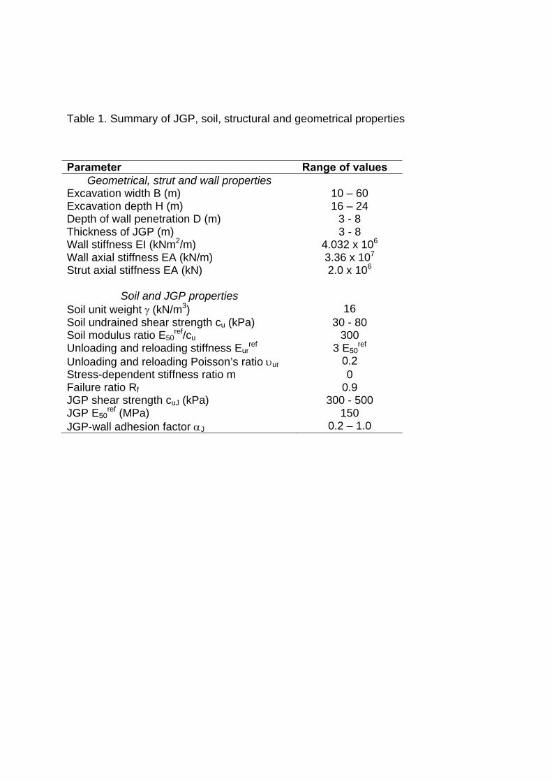
Table 1. Summary of JGP, soil, structural and geometrical properties
Parameter Range of values Geometrical, strut and wall properties
Excavation width B (m) 10 – 60 Excavation depth H (m) 16 – 24 Depth of wall penetration D (m) 3 - 8 Thickness of JGP (m) 3 - 8 Wall stiffness EI (kNm2/m) 4.032 x 10⁶ Wall axial stiffness EA (kN/m) Strut axial stiffness EA (kN)
3.36 x 10⁷
2.0 x 10⁶
Soil and JGP properties Soil unit weight γ (kN/m3) 16 Soil undrained shear strength cu (kPa) 30 - 80 Soil modulus ratio E50
ref/cu 300 Unloading and reloading stiffness Eur
ref 3 E50ref
Unloading and reloading Poisson’s ratio υur 0.2 Stress-dependent stiffness ratio m 0 Failure ratio Rf 0.9 JGP shear strength cuJ (kPa) 300 - 500 JGP E50
ref (MPa) 150 JGP-wall adhesion factor αJ 0.2 – 1.0
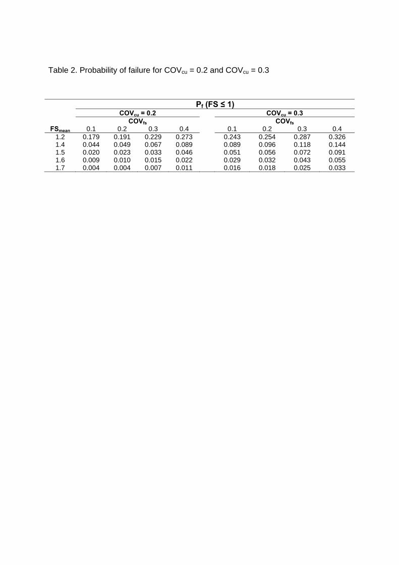
Table 2. Probability of failure for COVcu = 0.2 and COVcu = 0.3
Pf (FS ≤ 1) COVcu = 0.2 COVcu = 0.3
COVfs COVfs FSmean 0.1 0.2 0.3 0.4 0.1 0.2 0.3 0.4
1.2 0.179 0.191 0.229 0.273 0.243 0.254 0.287 0.326 1.4 0.044 0.049 0.067 0.089 0.089 0.096 0.118 0.144 1.5 0.020 0.023 0.033 0.046 0.051 0.056 0.072 0.091 1.6 0.009 0.010 0.015 0.022 0.029 0.032 0.043 0.055 1.7 0.004 0.004 0.007 0.011 0.016 0.018 0.025 0.033
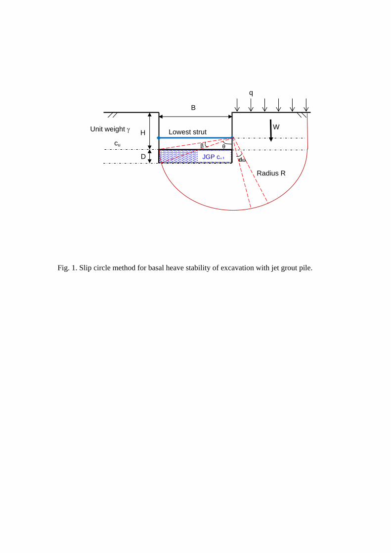
Fig. 1. Slip circle method for basal heave stability of excavation with jet grout pile.
B
H
Radius R
cu
Unit weight γ
D
q
W
JGP cuJ
β θ
Lowest strut
dω

Fig. 2. Modified Terzaghi method for basal heave stability of excavation with jet grout pile
B
H
B1 = B/√2
cuh
Unit weight γ
D
Surcharge q
fsJGP
W
cud
cub
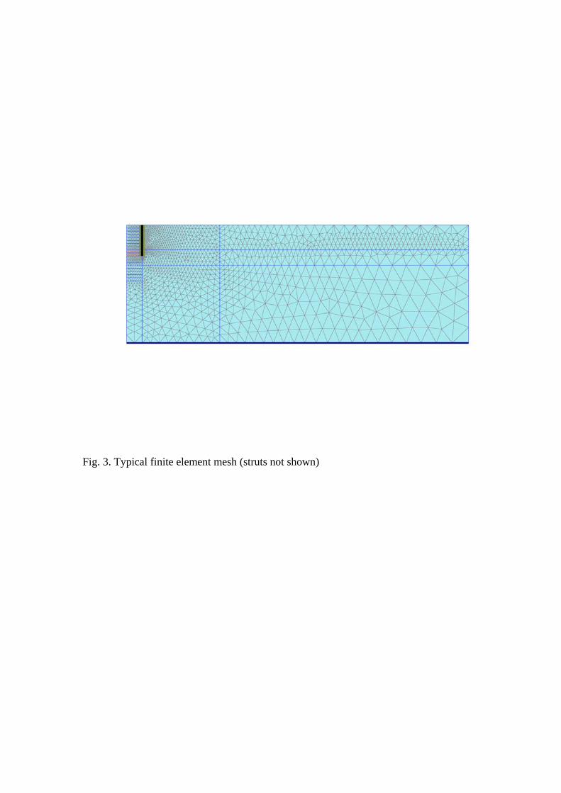
Fig. 3. Typical finite element mesh (struts not shown)
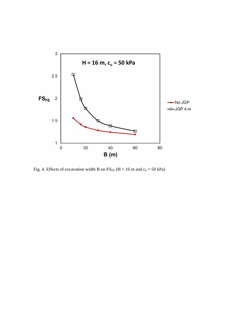
Fig. 4. Effects of excavation width B on FSFE (H = 16 m and cu = 50 kPa)
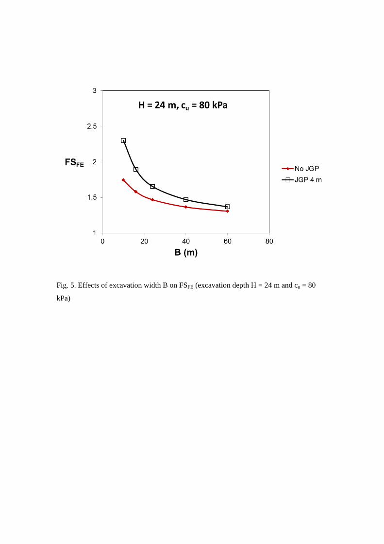
Fig. 5. Effects of excavation width B on FSFE (excavation depth H = 24 m and cu = 80
kPa)
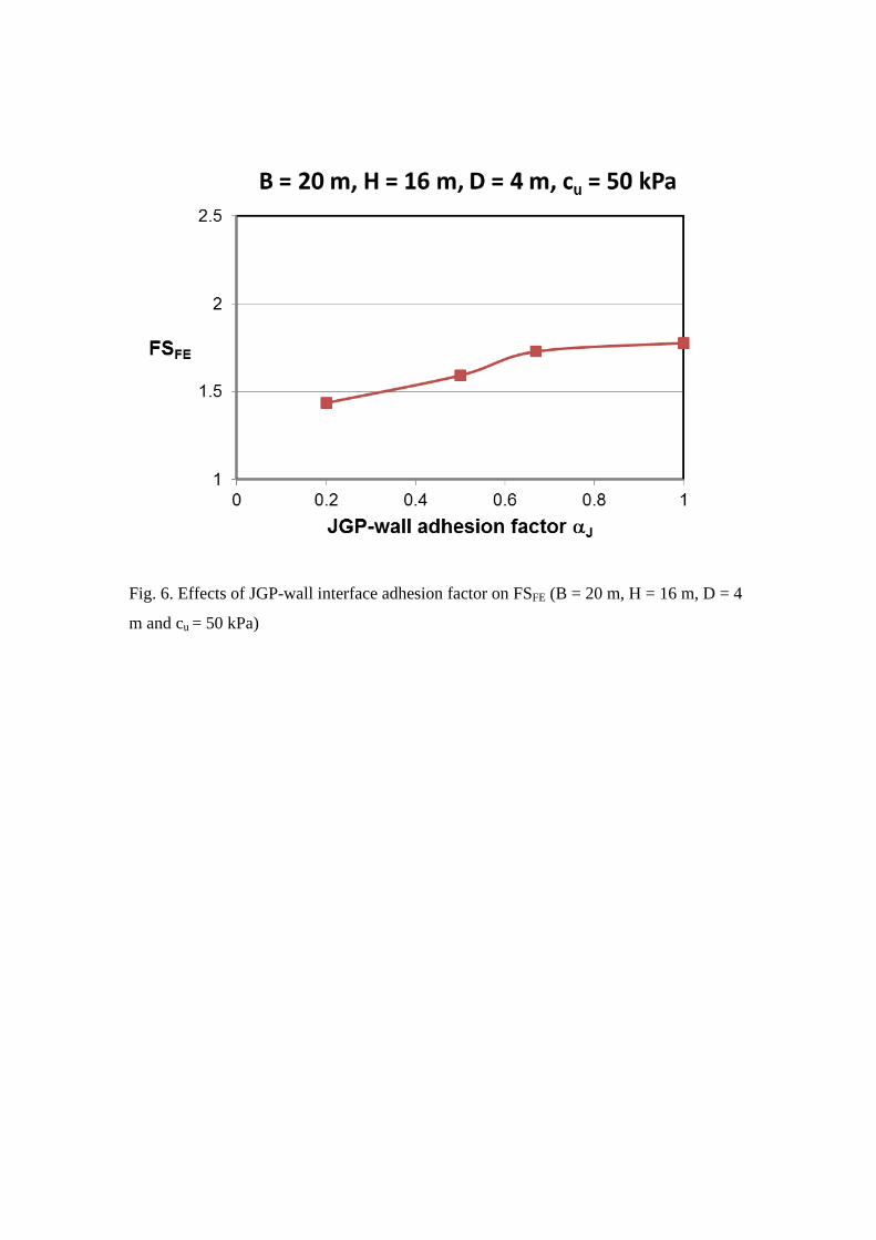
Fig. 6. Effects of JGP-wall interface adhesion factor on FSFE (B = 20 m, H = 16 m, D = 4
m and cu = 50 kPa)
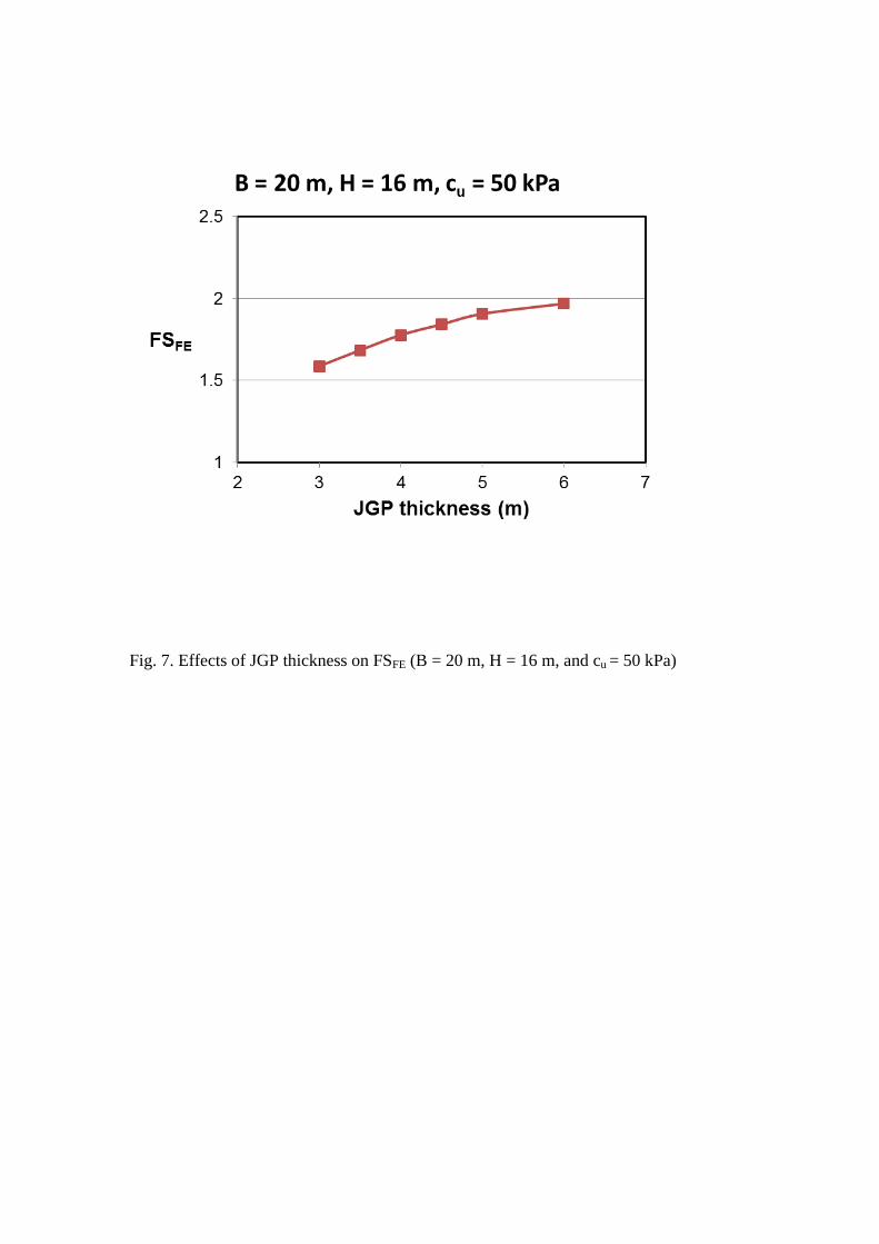
Fig. 7. Effects of JGP thickness on FSFE (B = 20 m, H = 16 m, and cu = 50 kPa)
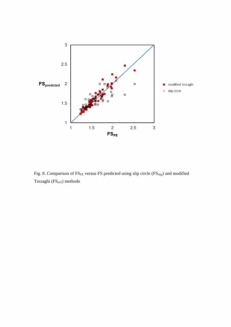
Fig. 8. Comparison of FSFE versus FS predicted using slip circle (FSslip) and modified
Terzaghi (FSmT) methods
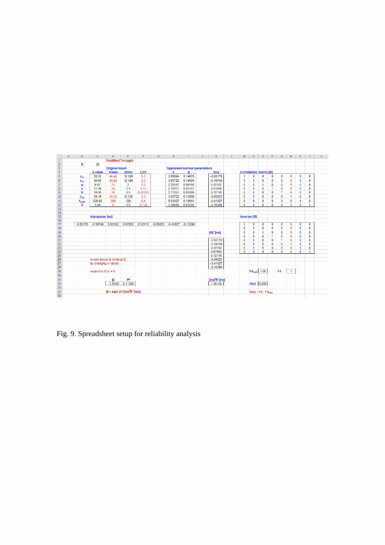
Fig. 9. Spreadsheet setup for reliability analysis
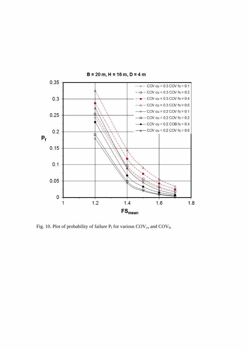
Fig. 10. Plot of probability of failure Pf for various COVcu and COVfs