Embed Size (px)
Citation preview
rJ"
I ...... . . ..
I DETECTION OF I STEEL CORROSION IN I BRIDGE DECKS AND I REINFORCED CONCRETE PAVEMENT .
I I I I I I I I I I I I
I
IOWA
1. 7 - T6BHR Highway Division 9 :D48 May 1977
Iowa Highway Research Board Project HR-156
Final Report
I I .1 1' -1 _J -1
I I 1· I ·1
1 I I· I
/7- T~'lf-/-R q : D Lf<i
DETECTION OF STEEL CORROSION IN BRIDGE DECKS AND
REINFORCED CONCRETE PAVEMENT
Iowa Highway Research Board
Project HR-156
Final Report
by Vernon J. Marks
May, 1977
Iowa Department of Transportation Highway Division
Off ice of Materials Ames, Iowa 50010
515-296-1447
I I .1
I I I
I ,,, I I I I .,
TABLE OF CONTENTS
Abstract
Introduction
Problem
Objectives
Equipment
Test Procedure
Evaluation
Conclusions
Recommendations
References
Appendix A - Sources and Costs of Corrosion Detection Device Components
Appendix B - Method of Test for Determining the Corrosion Potential of Bridge Deck Steel by the Electrical Potential Method
ii
iii
1
2
3
3
6
6
12
12
14
15
17
I I I I I I I I I I I I I I I I I ,, I
ABSTRACT
The Iowa Department of Transportation initiated this research
to evaluate the reliability, benefit and application of the corro
sion detection device. Through field testing prior to repair pro
jects and inspection at the time of repair, the device was shown
to be reliable.
With the reliability established, twelve additional devices
were purchased so that this evaluation procedure could be used
routinely on all repair projects. The corrosion detection device
was established as a means for determining concrete removal for
repair. Removal of the concrete down to the top reinforcing steel
is required for all areas exhibiting electrical potentials greater
than 0.45 Volt.
It was determined that the corrosion detection device was
not applicable to membrane testing.
The corrosion detection device has been used to evaluate cor
rosion of reinforcing steel in continuously reinforced concrete
pavement.
iii
I I I I I I I I I I I I I I I I I I I
DETECTION OF STEEL CORROSION IN BRIDGE DECKS AND REINFORCED CONCRETE PAVEMENT
INTRODUCTION
Bridge deck deterioration remains a major maintenance problem
for highway departments. The corrosion of the reinforcing steel
is considered to be the primary contributor to this problem.
The P.C. Concrete initially acts as an environment that pre-
vents corrosion of the reinforcing steel. This protection is
dependent upon the quality of the concrete. Deicing salts used
in winter maintenance introduce chlorides into the concrete and
destroy this initial protection. The chloride content sufficient
to permit steel corrosion within the concrete is referred to as
the corrosion threshold. This corrosion threshold is dependent
on the cement content of the concrete(l) and would be 1.4 lb./cu.yd.
for concrete in Iowa bridge decks (710 ·lbs. of cement/cu.yd.). If
the chloride content of the concrete reaches this level, the pro
tection has been destroyed and if sufficient moisture and oxygen
are present, corrosion will begin.
The rust formed by corrosion occupies considerably more volume
than the parent steel and this results in a force that exceeds the
strength of the concrete. This causes the concrete to crack hori-
zontally at the top steel and develop a.delamination. Water in-
filtration and subsequent freezing, along with the traffic, create
even greater pressures which cause spalling.
Iowa has developed a low slump, dense concrete bridge deck re
surfacing method for restoration of these deteriorated decks. This
program began more than twelve years ~go as a p~tching procedure.
It is now a nationally accepted method of bridge deck resurfacing.
I I I I I I I I I I I I l I I a I I I
In the early use of Iowa's method of P.C. patching and deck
resurfacing, the only means for determining the area of concrete
to be removed to the top reinforcing steel was by sounding. Using
a chain drag, hammer, or other tapping device, the delaminated area
was drawn on the surf ace to show the contractor the area for con
crete removal. The problem with this procedure was that delamination
and spalling would occur later around the periphery of the removal
area.
In the fall of 1970, the Federal Highway Administration gave
a demonstration in Iowa of a corrosion detection device developed
in a California research project. From this demonstration, suffi
cient interest was generated to initiate a research project in the
testing and application of the device.
PROBLEM
The problem was the application of the corrosion detection
device to repair procedures in Iowa. At the time of the FHWA
demonstration, the method had not been fully tested. Iowa was
second on the demonstration visits out of requests from approxi
~ately 40 states. The device had not been fully tested so the ·
demonstration team was gathering information along with demonstrat
ing the technique.
The device is a non-destructive testing procedure that measures
the electrical potential between the steel reinforcing and the ad
jacent concrete. Part of the application of the device is to be
able to correlate readings with known conditions of the steel.
2
I 1~
I ,, I I I I I I I I 'I I I I 1: II
OBJECTIVES
The objectives of this research were:
(1) To establish the reliability of the device as an aid in locating deck areas needing repair.
(2) To assign quantitative values indicating the types and extent of repair necessary.
(3) To evaluate the various types of overlays, waterproofing membranes and patching operations.
(4) To determine the usefulness of the technique on continuously reinforced concrete pavement.
EQUIPMENT
Two corrosion detection devices were built by purchasing
commercially available components and making minor electrical
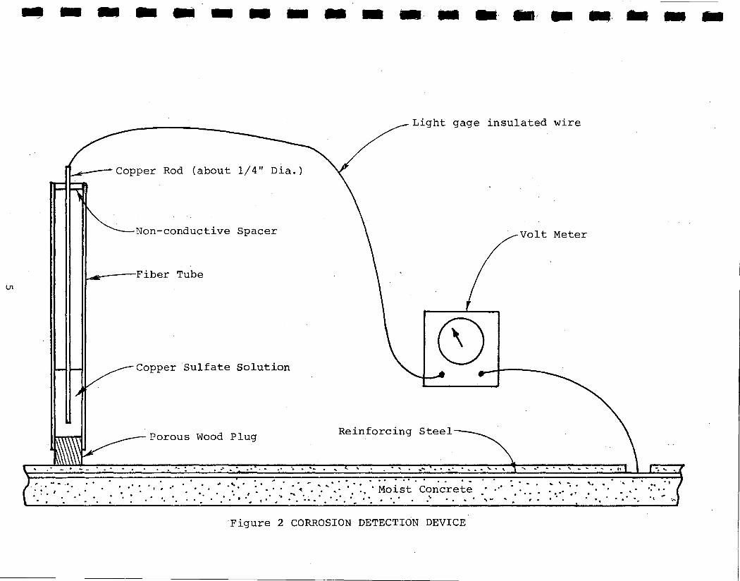
connections for assembly. The device (Figures 1 and 2) consists
of a high quality voltmeter, a "half-cell" probe of copper-copper
sulfate and two spools of light gage insulated electrical wire.
These firettwo devices were funded through the research
project and were assembled at a cost of $550 each. When the
project was initiated a high quality voltmeter was considered
essential. Because this was research, there was an extra effort
to assure that a voltmeter with adequate capability was purchased.
The voltmeters for these first two devices had more capabilities
and quality than needed. Much of the expense for these first two
devices was due to a more expensive voltmeter than necessary.
The components for the device shown in Figure 1 are those
currently being used in the inspection of repair projects. Pre-
sently, the device can be assembled for about $275. A more detailed
3
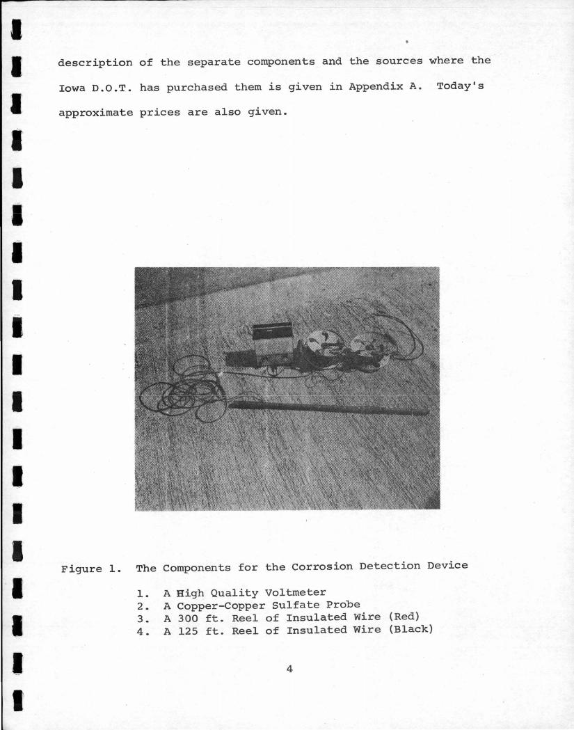
I ~ description of the separate components and the sources where the
Iowa D.O.T. has purchased them is given in Appendix A. Today's
I I I I I I I I I I I I I I I I I
approximate prices are also given.
Figure 1. The Components for the Corrosion Detection Device
1. A High Quality Voltmeter 2. A Copper-Copper Sulfate Probe 3. A 300 ft. Reel of Insulated Wire (Red) 4. A 125 ft. Reel of Insulated Wire (Black)
4
- - .. - .. - - - - - •.. - •· -i - •. - - -
Light gage insulated wire
Non-conductive Spacer Volt Meter
--Fiber Tube
Copper Sulfate Solution
Porous Wood Plug Reinforcing Steel
. . . . ... : . . . -· .. . . . . . .. · .. · ·. .. .... . ' .. .. ' .. ...... . . .. . . ..... "' " ' ...... -· .. .. . ' .. ... . .. . ,. ,. ....... ··.. . .
: • • I • • • • . .. .. . . • • • • • t - •• . .
·. ·. . . . .,,,.·,.,,,.·.·..- ...... ··· .. ···:···· ......
· ·. · : . · · ~ . . , · · ... · Moist Concrete . .. . . ·' ' . . .. .......... ·.. . . . . . . . . . . .~ . . .. . ~ " . . ...
Figure 2 CORROSION DETECTION DEVICE
. . . . . .. ,_ . ,
. ~ ' · . . '· . ' . . . · ... •' . . . . .. . . ' . . ., ., · ...
.,
I I I I I I I I I I I I I I I I I
I I I
TEST PROCEDURE
The test procedure adopted was essentially the same as that
of the FHWA demonstration team. The copper rod suspended in the
saturated copper sulfate solution of the "half-cell" probe pro
duces a constant potential that is electrically connected to oppose
the galvanic "half cell" of the bridge deck. This is done by con
necting one lead of the voltmeter to the reinforcing steel and the
other to the probe. Each location on the bridge is wetted to pro
vide good electrical contact between the probe and surface. A de
tailed procedure "Test Method No. ·Iowa 1008-A" is included in Ap
pendix B. In the original procedure, the connection to the rein
forcing steel was normally made through either the metal expansion
assembly or a bar chair under the deck. Experience has shown that
a poor connection between these and the mat of reinforcing steel
will yield erroneous readings. The present recommended procedure
is to connect directly onto the reinforcing steel.
EVALUATION
The device was developed by the State of California and much
of the subsequent evaluation has been by California. The resultant
potential from the corrosion detection device is a negative value,
but the potential is commonly used without notation of the minus.
Potentials in this report will be referred to as a numeric voltage
value and the minus sign will not be used. In studies by California,(2)
it has been shown that half-cell potential values greater than 0.35
volt to the copper-copper sulfate probe generally exhibit active
corrosion. Values between 0.30 and 0.35 Volt are inconclusive, but
6
I I I I I I I I I I I I I I ·1 I I I I
vaiues less than 0.30 volt show the steel to be passive or chemi
cally inhibited from corrosion. These values do not measure the
amount of chloride that is present at the reinforcing stee~but
only indicate if it is sufficient to permit active corrosion.
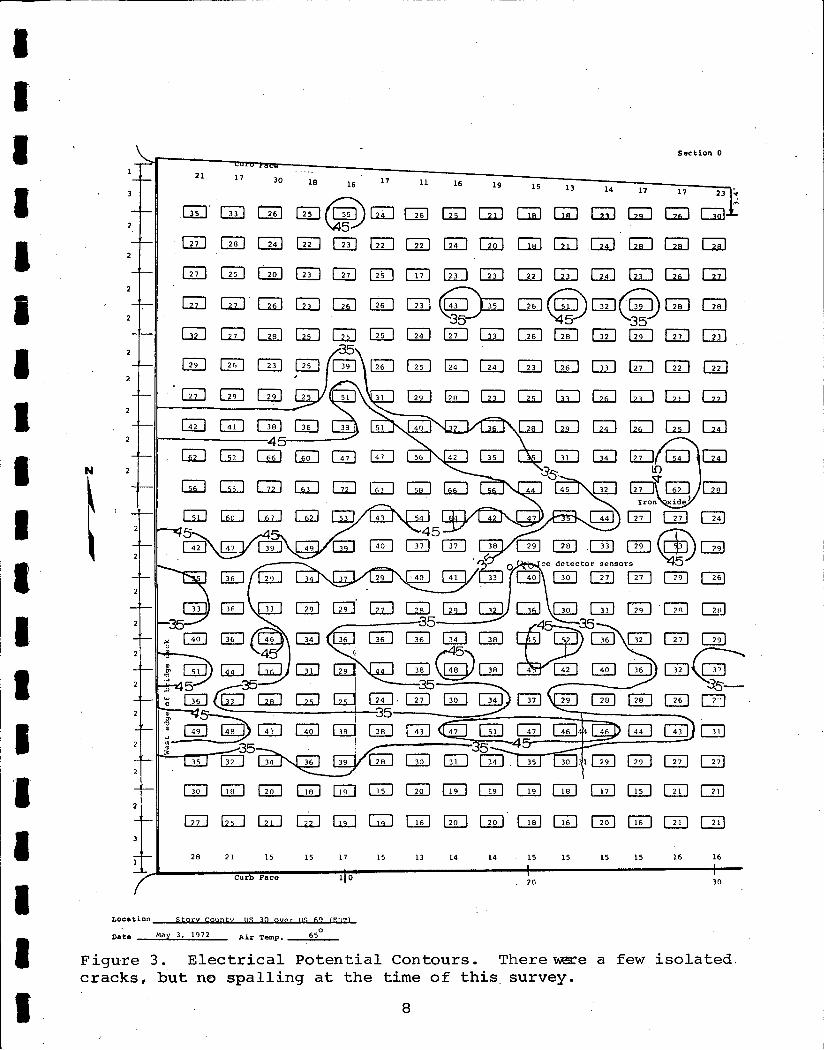
To determine the reliability of the device, corrosion testing
was performed on a number of bridge decks in Iowa that were scheduled
for repair. Electrical potential contours (Figure 3) were plotted
for some of these decks. After the concrete removal in preparation
for resurfacing, a visual observation of the corrosion of the rein
forcing steel showed a relationship to corrosion readings.
In one case, corrosion detection contours were laid out for
a selected area on a bridge deck. At that time, there was essen
tially no visible deterioration (Figure 3) of the deck. There was,
however, one definable area where corrosion detection readings were
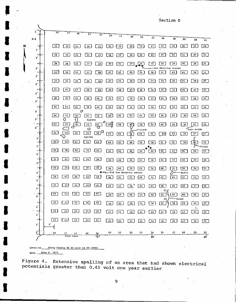
greater than 0.45 volt. A visual inspection of this same area one
year later showed considerable spalling (Figure 4). This further
supports the relationship of the potential and active corrosion.
Bridge deck resurfacing in Iowa has been relatively success
ful even prior to the introduction of the corrosion detection de
vice. Prior to 1974, evaluation of bridge decks being considered
for repair and the determination of the extent of the repair, were
based almost entirely on the amount of spalling and delamination
present. In 1974, corrosion detection readings were adapted to
be used with sounding methods to determine areas for concrete
7
I· I I I I I I I I I I I I I I I I I I
N
2
2
2
Section 0
0 G£J Cii] G:u Clli GD QIJ G QD QD OD 0 0 0 0
QU 00 WJCill~QiJ OIJ~ GODG ~GQD
0 0 G:Ll GD CiiJ 0 @J QD W 0 0 OD ~ 0 ITO . . ~Ice detector sensor
CEJ E2D ~ 0 ~ CID ITO G GD 0 0 QD @J G lliJ
0 0 @J 0 ~ C2£J ~ Cill QD OD 0 OD El OD @J
0 0 @:J 0 0 G 0 0 ~ GD 0 0 ffi::J 5J 0
DD Cill G Cill UL! ~ @=) 0 0 GJ 0 G @:J ~ !20
Cill (22] 0 ~ OD 0 @:J 0 [Kl QTI ~ 0 @=J {~ @:J 0 .-z.__Qld ice detector sensor 0..-.__ Spall
OIJ B OD Cill 0 CiiJ 0 0 @J Cill 82:::.J GD @J ITiJ ~
0 CID C3IJ GD 0 0 GD GS>, 0 ~ @=) 0 ~ 0 GD
0~0 8D 39 ~crack
0 OD .GD -;.
0 0 GD
':_i,_l.~---.:·2~7:__~~21!:__~1~3'__~~1~4~-=f-~~~13:__~1~2~~~11:__~~13~~~~.:.__4~=15-:----~-l-5~~14~~-l-S_.~-lt-curb Face l o· Jo· 30
Location __ S_t~ County US 30 over us 69 (EBT)
Date • June 6, 1973
Figure 4. Extensive spalling of an area that had shown electrical potentials greater than 0.45 volt one year earlier
9
I I I I I I I I I I I I I I I I I I I
removal. It was decided that all areas exhibiting potential
values greater than 0.45 volt should have the concrete removed
down to the top reinforcing steel. This decision was based on
past repair experience and the conclusion that cracking and spalling
were eminent for these areas. This corrosion detection data was
to be obtained for use in design of the repair, as well as being
used at the time of construction if all of the concrete above the
reinforcing steel was not removed. This criteria of 0.45 volt was
established and the method of incorporating it into a project has
been by a note on the plans. The plans note that the engineer shall
conduct a survey at the time of construction and all areas with
potentials greater than 0.45 volt shall be included for Class A
repair. Class A repair requires removal of the concrete to below
the top reinforcing steel. The 0.45 value and the note on the
plans remain as present practice.
Twelve more corrosion detection devices were purchased to
implement this new program. A training program was initiated for
maintenance and construction personnel in the proper operation and
testing procedure. The field personnel, using the twelve units
purchased in 1974, have routinely conducted testing of the bridge
decks prior to design. They have also provided the testing re
quired at the time of construction. The device has been adopted
as a reliable aid in locating deck areas needing repair.
This device is being used as one method of post construction
evaluation. A program of systematic testing of areas on certain
10
I I I I I I I I I I I I I I I I I I I
designated bridge decks that have been repaired using the Iowa
method of restoration is being conducted. Even after resurfacing
with P.C. concrete, the device will yield voltage readings that
may be used to show areas of active corrosion.
The units have been used for more than six years with rela
tively few problems. Some problems have been encountered in ob
taining a good connection to the reinforcing steel. Another pro
blem has been in proper maintenance of the copper-copper sulfate
probe. The copper sulfate solution must be saturated to yield
a standard potential. There tas been at least one instance where
a diluted solution gave erroneous results. There have been a num
ber of cases where the external fiber tube of the probe had to be
replaced. This was due to breakage either from improper handling
or permitting the copper sulfate solution to freeze. The volt
meters are periodically checked and there has been one instance
where recalibration was necessary. These are generally the only
problems encountered with the device.
It was determined that the principle of the corrosion detec
tion device was not applicable to testing of membrane systems and,
therefore, it was never used for this purpose. A similar test was
developed on the basis of resistivity for the evaluation of membranes.
Highway Research Project HR-1004, 11Corrosion of Steel in Con
tinuously Reinforced Concrete Pavement" was conducted using the
device to determine if there was active corrosion. The research
11
I I I I I I I I I I I I I I I I I I I
was conducted in 1974 on fourteen different Interstate pavement
projects. Readings were taken directly over a reinforcing bar at
transverse cracks and at midpoints between the transverse cracks.
Electrical potentials were considered on the basis of the 0.35 volt
criteria based upon the California research, but it has not been
proveri that this value is applicable to pavement. This 1974 re-
search did not indicate a serious corrosion problem but results
did suggest that corrosion could become a concern of the future.
This project did demonstrate the usefulness of the corrosion de-
tection device on continuous reinforced concrete pavement.
CONCLUSIONS
The conclusions that can be gained from this research are:
1. The corrosion detection device is a reliable aid in locating deck areas needing repair.
2. The requirement for removal.of areas showing a potential numerically greater than 0.45 volt has improved the bridge deck restoration program.
3. The corrosion detection device is relatively free of maintenance.
4. The device is not applicable to the evaluation of membrane systems.
5. The device is useful as a technique for evaluating cont_inuously reinforced concrete.
RECOMMENDATIONS
It is recommended that research be conducted to evaluate the
p::-esent condition of areas on bridge deck restoration projects
12
~a
I I I I I I I I I I I I I I I I I I
where the concrete was not removed and readings were in the 0.35
to 0.45 volt range at the time of construction. This data should
be used to reevaluate the use of the 0.45 volt value and consider
the use of a 0.35 volt criteria that would require a greater amount
of concrete removal.
13
I ! I
I I I I I I I I I I I I I I I· I I
References
REFERENCES
1. Clear, K.C. and Hay, R.E., "Time-to-Corrosion of Reinforcing
Steel in Concrete Slabs - Volume 1: Effect of Mix Design and
Construction Parameters," Report No. FHWA-RD-73-32, Federal
Highway Administration, Interim Report, April 1973.
2. Stratfull, Richard F., "Corrosion Autopsy of a Structurally
Unsound Bridge Deck'' Highway Research Record No. 433, 1973.
14
I I I I I I I I I I I I I I I I I I I
Appendix A
Sources and Costs of Corrosion Detection Device Components
15
I I I I I I I I I I I I I I I I I I I
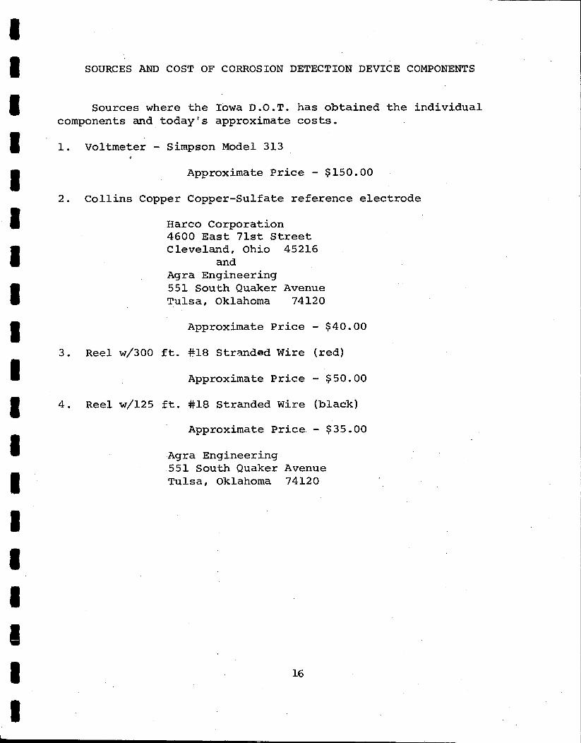
SOURCES AND COST OF CORROSION DETECTION DEVICE COMPONENTS
Sources where the Iowa D.O.T. has obtained the individual components and today's approximate costs.
1. Voltmeter - Simpson Model 313
2.
3.
Approximate Price - $150.00
Collins Copper Copper-Sulfate reference electrode
Harco Cdrporation 4600 East 7lst Street Cleveland, Ohio 45216
and Agra Engineering 551 South Quaker Avenue Tulsa, Oklahoma 74120
Approximate Price - $40.00
Reel w/300 ft. #18 Stranded Wire {red)
Approximate Price - $50.00
4. Reel w/125 ft. #18 Stranded Wire {black)
Approximate Price - $35.00
Agra Engineering 551 South Quaker Avenue Tulsa, Oklahoma 74120
16
I I I I I I I I I I I I I I I I I I I
Appendix B
Method of Test for Determining the Corrosion Potential of Bridge
Deck Steel by the Electrical Potential Method
17
I I I I I I I I I I I I I I I I I I I
Test Method No. Iowa 1008-A March 1977
IOWA DEPARTMENT OF TRANSPORTATION HIGHWAY DIVISION
Office of Materials
METHOD OF TEST FOR DETERMINING THE CORROSION POTENTIAL OF BRIDGE DECK STEEL BY THE ELECTRICAL POTENTIAL METHOD
Scope
Corrosion of reinforcing steel is caused by an electric current flowing from the rebar at one point (the anode) into the . bar at another point (the cathode) • During active corrosion an electrical (potential) difference exists between the anode and the cathode.
When this electrical potential difference is -.35 volts or greater (-.40 or -.50) there is a high probability that active corrosion of the reinforcing steel is occurring. The corrosion product (rust) exerts tremendous forces on the concrete resulting in spalls.
This test method describes the procedure to be used in determining the corrosion level of reinforcing steel in a concrete bridge deck when ·utilizing a copper sulfate reference electrode (half cell) •
Procedure
A. Apparatus
1. Voltmeter--Simpson Model 313-2 2. Copper - copper sulfate probe 3. Wire 4. water*, pail and squeeze bottle 5. Hammer and chisel 6. 50' or 100' tape 7. Marking keel 8. Data and layout sheet
*(Wetting agent necessary in water when using through asphaltic concrete.)
Bo Project Information
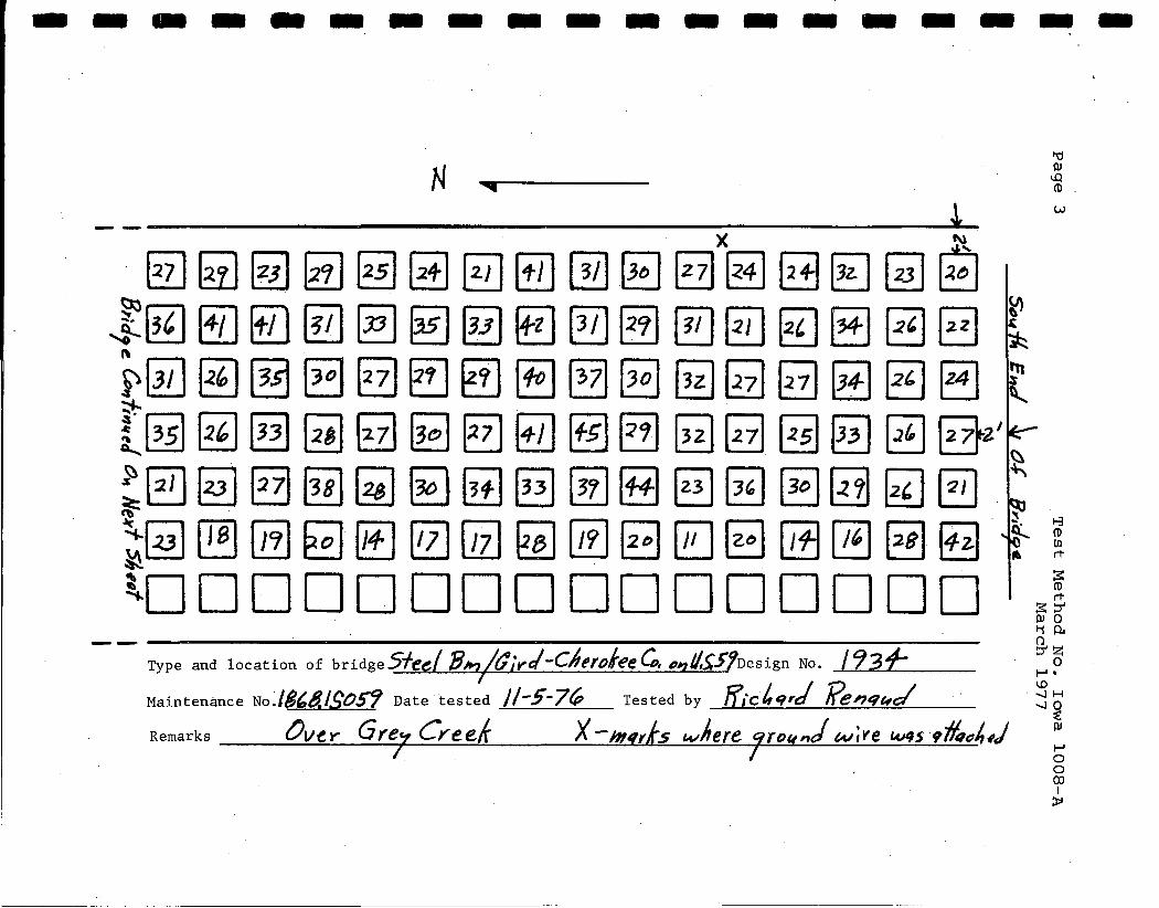
The following information should be recorded on the data and layout sheet. See example on page 3.
1. Type and location of bridge 2. Design No. 3. Maintenance Noo 4. Date Tested and by whom 5. Layout showing location of
each test point 6. Location where ground wire
was attached to deck steel 7. Electrical potential readings 8 o North arrow 9. Longitudinal dimension
required for skew
C. Voltmeter Calibration
The following steps must be completed prior to initiating the test procedure •
1. With the circuit selector switch to "OFF", check to see that the pointer is set on the "O" mark at the left side of the scale. If the pointer is not on "0", set the pointer to 11 0" by turning the screw in the center of the meter.
2o Check battery by setting circuit selector switch to "BATT". Pointer must be read to the right of the "BATTERY OK" mark on meter face.
3. Turn range switch to 1 (one) volt.
4. Turn the circuit selector switch to "+DC", connect the positive lead and black wire from the meter together and turn the knob marked "ZERO" clockwise· or counterclockwise until the pointer rests over the "0" mark at the left side of the scaleo
5. Connect positive lead from meter to red wire connected to the probe, and the black wire from meter to the black wire connected to the deck steel.
D. Test Procedure
1. Lay out 4' x 4' grid pattern on bridge deck. Be sure and measure the test points very accurately, since the test points may have to be relocated at a later date. Additional readings may be required due to skew angles. ·
2. Wet each point to be read and allow to soak a minimum of 10 to 15 minutes.
3. Connect the black wire (ground) to a steel expansion plate or drain which is tied into the steel reinforcing mat of the deck being
I I I I I I I I I I I I I I I I I I I
Test Method No. Iowa 1008-A March 1977
tested. If this is not possible, connect onto the steel support chairs located under the bridge deck.
4. Check to be sure that coppersulfate fills the probe and connect the red wire to the probe.
5. Take readings by placing the probe on the point to be tested and record each reading on the data sheet. The reading should be taken after the needle stops fluctuating .
CAUTION: Always let the pointer settle before taking readings. If the pointer continues to waver, there may be a bad c onnection or interference such as power lines in the area. The maximum reading possible is . 78 v. If a reading above .78 v. is obtained, the meter is probably not set correctly.
E. Copper-Sulfate Solution
The copper-sulfate solution for the probe is available through the Materials Laboratory Receiving Office. However, if field mixing of the solution becomes necessary, copper-sulfate crystals or powder can be obtained through chemical supply stores. The test requires using a saturated copper-sulfate/ water solution. The amount of copper-sulfate needed for saturation varies with water temperature. Copper-sulfate must be added with vigorous stirring until a few crystals appear in the solution. The amount used should be above 14% by weight of the amount of water used.
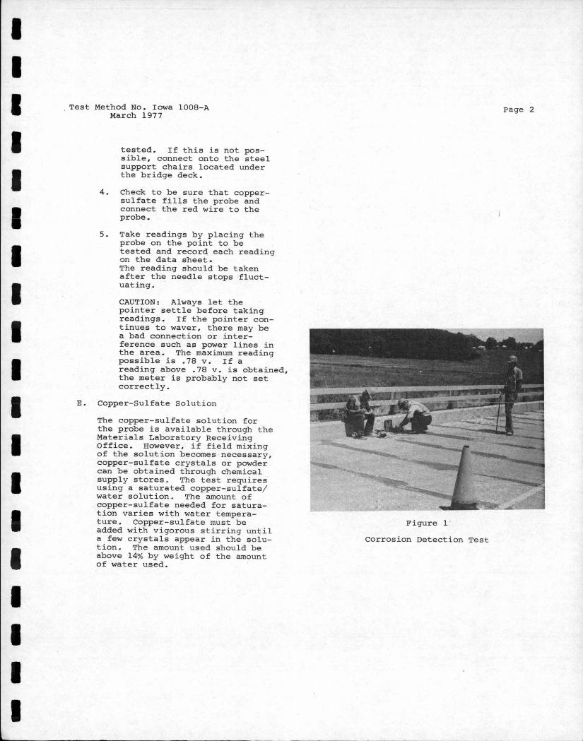
Page 2
Figure l ·
Corrosion Detection Test
-------------------N -.... ---
~ (1) rt
~ ::r' OJ 0 Ii 0.. -- ()
Type and location of bridge 5fee/ 8MjdiyJ-C/Jerolee C,, ""l/,~5'/nesign No. / 93f- : ? Maintenance NoJ8(,8,/S059 Date tested //-5-7~ Tested by {f,·c~qrd 'J?enq~d · j ~
~
Remarks tJve. r- G "7 Cl'ee/r X -hlfrJs where JfD((nJ wire 4Jqs ·9£(;4,j ; 0 00 I
::i:i