Embed Size (px)
Citation preview
About the Instructor About the Sponsor Ask an Expert
This Online Learning Seminar is available through a professional courtesy provided by:
MBCI14031 West Hardy Houston, TX 77060Tel: (281) 445-8555Fax: (281) 445-8110Toll-Free: (877) 713-6224Email: [email protected]: www.mbci.com
Designing Standing Seam Metal Roof Systems
Audubon National Wildlife Refuge, Coal Harbor, ND
Slide 5 of 73©2021 ∙ Table of Contents < >
About the Instructor About the Sponsor Ask an Expert
Purpose:
Standing seam metal roofs (SSMRs) have many functional and aesthetic advantages and a long history of reliable performance. They are system designs in which all the pieces must work together in complete harmony to have a successful outcome. This course examines the criteria that should be considered when selecting a standing seam roof panel for a project and the best practices to ensure a properly designed, detailed, and installed standing seam roof.
Learning Objectives:
At the end of this program, participants will be able to:
• Discuss the criteria examined when selecting a roof panel for a project to ensure expected benefits, such as durability, fire and impact resistance, watertight construction, and extended life cycle.
• Identify the applicable standards and test methods for SSMRs and discuss why SSMRs can resist the uplift forces typically imposed by extreme winds, protecting the structure and its occupants.
• Describe the key conditions that can affect the performance of an SSMR in a cold climate and summarize the steps designers can take to mitigate any potential negative effects of snow and ice.
• Design and detail SSMRs to avoid complicated situations that can lead to leakage and other failures by examining SSMR design conditions that require special attention.
• Examine common installation errors and explain how they affect an SSMR's service life.
Purpose and Learning Objectives
Slide 6 of 73©2021 ∙ Table of Contents < >
About the Instructor About the Sponsor Ask an Expert
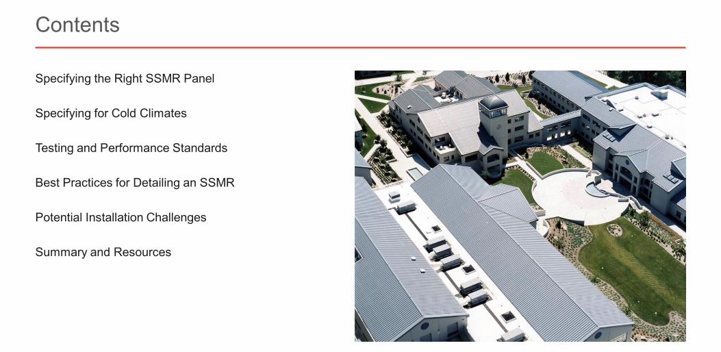
Specifying the Right SSMR Panel
Specifying for Cold Climates
Testing and Performance Standards
Best Practices for Detailing an SSMR
Potential Installation Challenges
Summary and Resources
Contents
Slide 7 of 73©2021 ∙ Table of Contents < >
About the Instructor About the Sponsor Ask an Expert
Specifying the Right SSMR Panel
Slide 8 of 73©2021 ∙ Table of Contents < >
About the Instructor About the Sponsor Ask an Expert
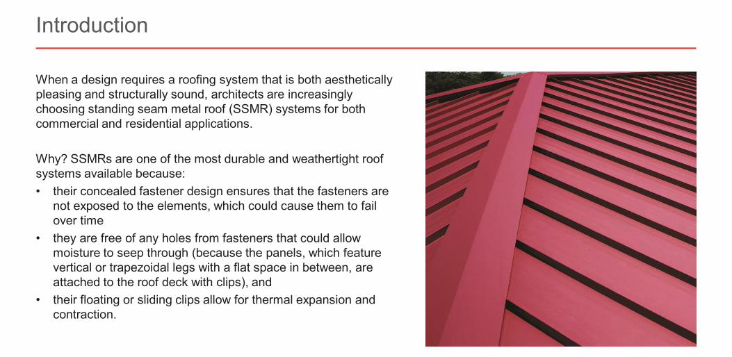
When a design requires a roofing system that is both aesthetically pleasing and structurally sound, architects are increasingly choosing standing seam metal roof (SSMR) systems for both commercial and residential applications.
Why? SSMRs are one of the most durable and weathertight roof systems available because:• their concealed fastener design ensures that the fasteners are
not exposed to the elements, which could cause them to fail over time
• they are free of any holes from fasteners that could allow moisture to seep through (because the panels, which feature vertical or trapezoidal legs with a flat space in between, are attached to the roof deck with clips), and
• their floating or sliding clips allow for thermal expansion and contraction.
Introduction
Slide 9 of 73©2021 ∙ Table of Contents < >
About the Instructor About the Sponsor Ask an Expert
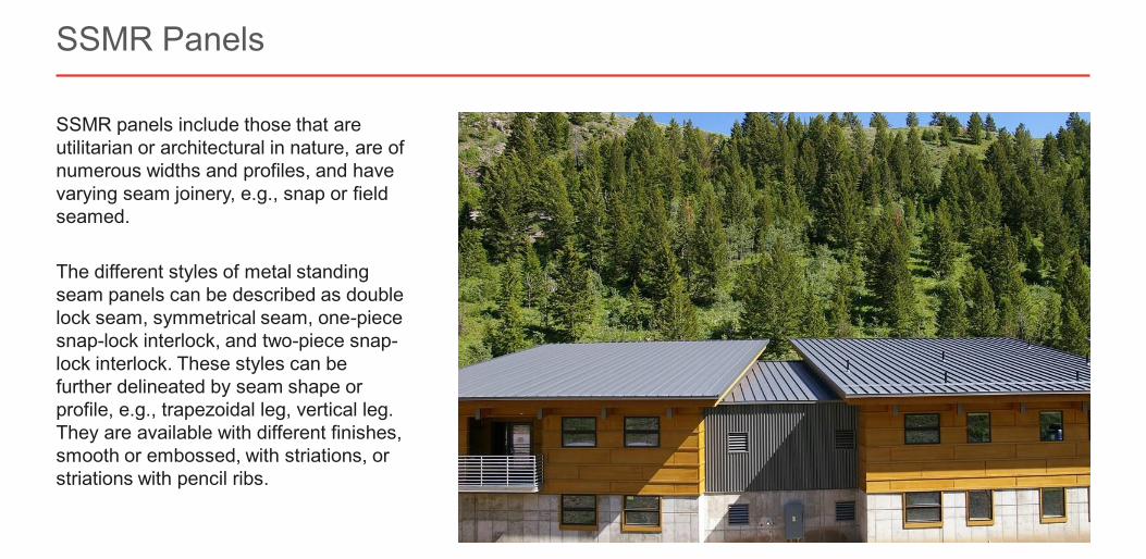
SSMR panels include those that are utilitarian or architectural in nature, are of numerous widths and profiles, and have varying seam joinery, e.g., snap or field seamed.
The different styles of metal standing seam panels can be described as double lock seam, symmetrical seam, one-piece snap-lock interlock, and two-piece snap-lock interlock. These styles can be further delineated by seam shape or profile, e.g., trapezoidal leg, vertical leg. They are available with different finishes, smooth or embossed, with striations, or striations with pencil ribs.
SSMR Panels
Slide 10 of 73©2021 ∙ Table of Contents < >
About the Instructor About the Sponsor Ask an Expert
The benefits of an SSMR can be easily negated if a designer fails to understand the details and application parameters of a specific SSMR system. When the roof system chosen isn’t the right one for the application, the result can be a roof that leaks and fails to meet the performance demands of the building and its environment.
It is also essential to specify a panel that can be used in every design element in the roof project. Design coupled with trim details and how the panels are to be fastened to the substructure can be deciding factors in choosing the proper roof.
SSMR panel selection criteria includes the:• properties of the roof, including slope, geometry, substrate, and architectural features• panel profile• panel performance requirements and testing standards• project location and local climate, and• engineering design.
Match the Roof System to the Project
Slide 11 of 73©2021 ∙ Table of Contents < >
About the Instructor About the Sponsor Ask an Expert
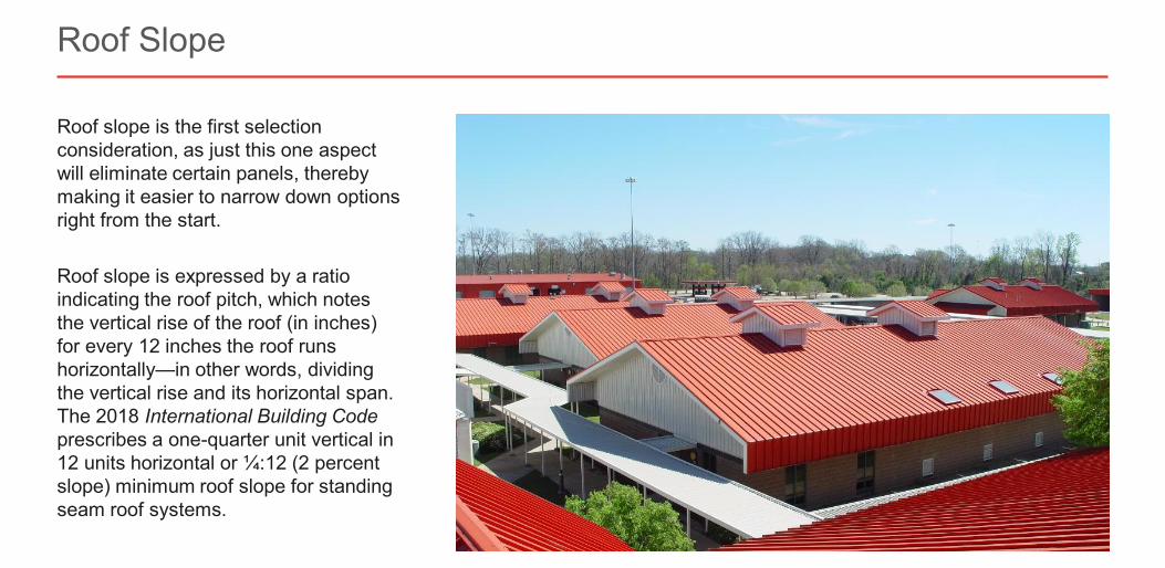
Roof slope is the first selection consideration, as just this one aspect will eliminate certain panels, thereby making it easier to narrow down options right from the start.
Roof slope is expressed by a ratio indicating the roof pitch, which notes the vertical rise of the roof (in inches) for every 12 inches the roof runs horizontally—in other words, dividing the vertical rise and its horizontal span. The 2018 International Building Codeprescribes a one-quarter unit vertical in 12 units horizontal or ¼:12 (2 percent slope) minimum roof slope for standing seam roof systems.
Roof Slope
Slide 12 of 73©2021 ∙ Table of Contents < >
About the Instructor About the Sponsor Ask an Expert
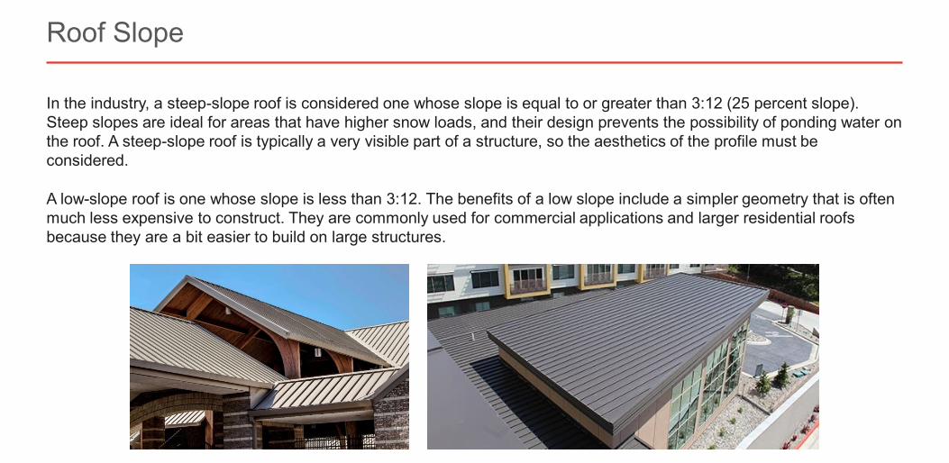
In the industry, a steep-slope roof is considered one whose slope is equal to or greater than 3:12 (25 percent slope). Steep slopes are ideal for areas that have higher snow loads, and their design prevents the possibility of ponding water on the roof. A steep-slope roof is typically a very visible part of a structure, so the aesthetics of the profile must be considered.
A low-slope roof is one whose slope is less than 3:12. The benefits of a low slope include a simpler geometry that is often much less expensive to construct. They are commonly used for commercial applications and larger residential roofs because they are a bit easier to build on large structures.
Roof Slope
Slide 13 of 73©2021 ∙ Table of Contents < >
About the Instructor About the Sponsor Ask an Expert
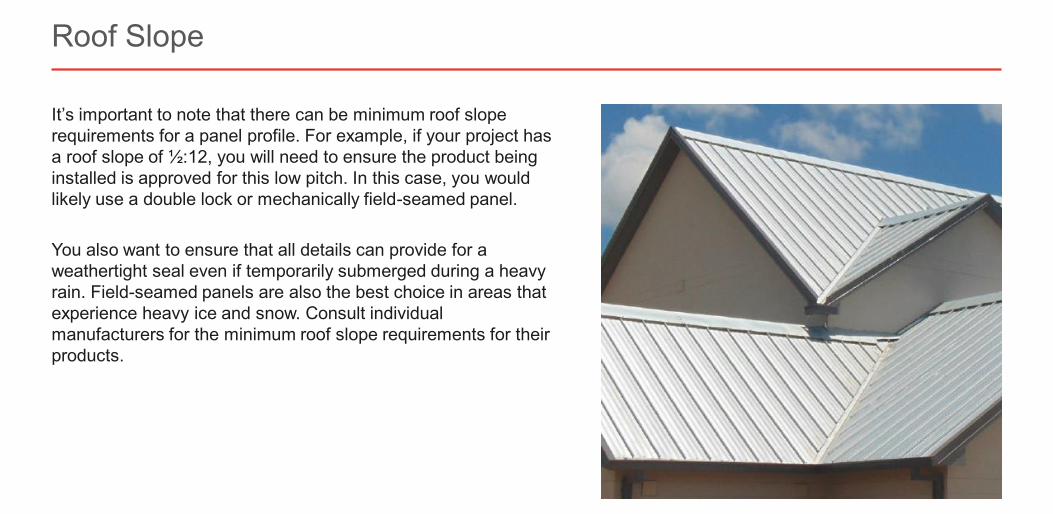
It’s important to note that there can be minimum roof slope requirements for a panel profile. For example, if your project has a roof slope of ½:12, you will need to ensure the product being installed is approved for this low pitch. In this case, you would likely use a double lock or mechanically field-seamed panel.
You also want to ensure that all details can provide for a weathertight seal even if temporarily submerged during a heavy rain. Field-seamed panels are also the best choice in areas that experience heavy ice and snow. Consult individual manufacturers for the minimum roof slope requirements for their products.
Roof Slope
Slide 14 of 73©2021 ∙ Table of Contents < >
About the Instructor About the Sponsor Ask an Expert
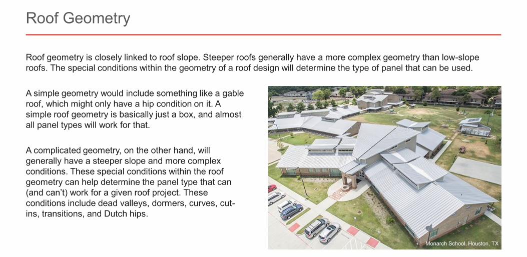
Roof geometry is closely linked to roof slope. Steeper roofs generally have a more complex geometry than low-slope roofs. The special conditions within the geometry of a roof design will determine the type of panel that can be used.
Roof Geometry
Monarch School, Houston, TX
A simple geometry would include something like a gable roof, which might only have a hip condition on it. A simple roof geometry is basically just a box, and almost all panel types will work for that.
A complicated geometry, on the other hand, will generally have a steeper slope and more complex conditions. These special conditions within the roof geometry can help determine the panel type that can (and can’t) work for a given roof project. These conditions include dead valleys, dormers, curves, cut-ins, transitions, and Dutch hips.
Slide 15 of 73©2021 ∙ Table of Contents < >
About the Instructor About the Sponsor Ask an Expert
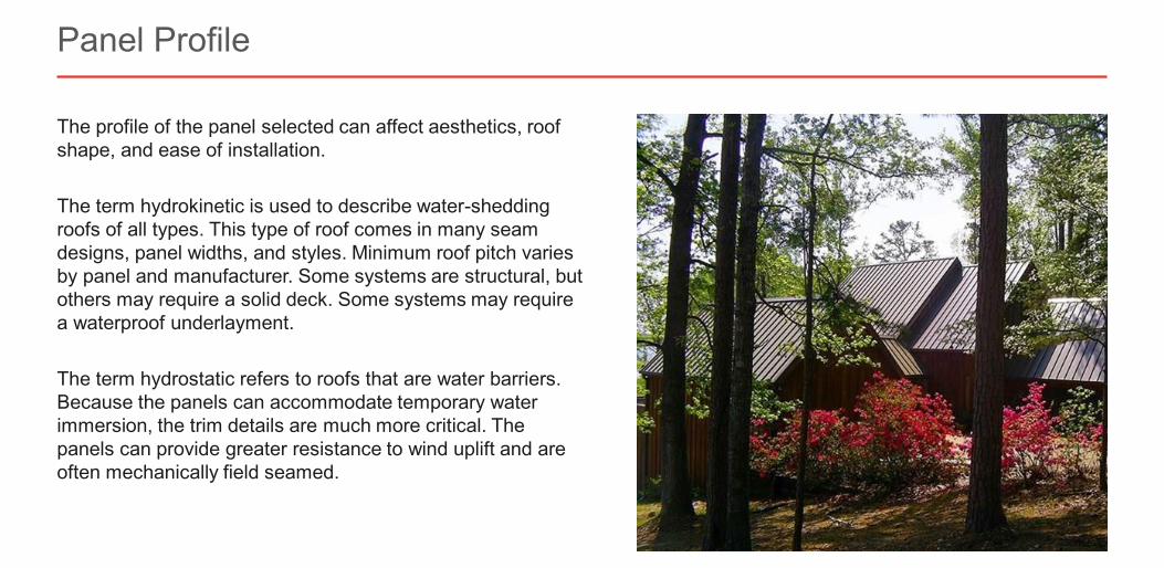
The profile of the panel selected can affect aesthetics, roof shape, and ease of installation.
The term hydrokinetic is used to describe water-shedding roofs of all types. This type of roof comes in many seam designs, panel widths, and styles. Minimum roof pitch varies by panel and manufacturer. Some systems are structural, but others may require a solid deck. Some systems may require a waterproof underlayment.
The term hydrostatic refers to roofs that are water barriers. Because the panels can accommodate temporary water immersion, the trim details are much more critical. The panels can provide greater resistance to wind uplift and are often mechanically field seamed.
Panel Profile
Slide 16 of 73©2021 ∙ Table of Contents < >
About the Instructor About the Sponsor Ask an Expert
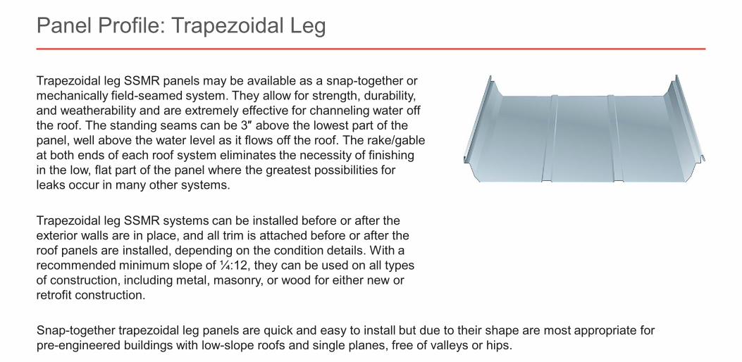
Trapezoidal leg SSMR panels may be available as a snap-together or mechanically field-seamed system. They allow for strength, durability, and weatherability and are extremely effective for channeling water off the roof. The standing seams can be 3″ above the lowest part of the panel, well above the water level as it flows off the roof. The rake/gable at both ends of each roof system eliminates the necessity of finishing in the low, flat part of the panel where the greatest possibilities for leaks occur in many other systems.
Trapezoidal leg SSMR systems can be installed before or after the exterior walls are in place, and all trim is attached before or after the roof panels are installed, depending on the condition details. With a recommended minimum slope of ¼:12, they can be used on all types of construction, including metal, masonry, or wood for either new or retrofit construction.
Panel Profile: Trapezoidal Leg
Snap-together trapezoidal leg panels are quick and easy to install but due to their shape are most appropriate forpre-engineered buildings with low-slope roofs and single planes, free of valleys or hips.
Slide 17 of 73©2021 ∙ Table of Contents < >
About the Instructor About the Sponsor Ask an Expert
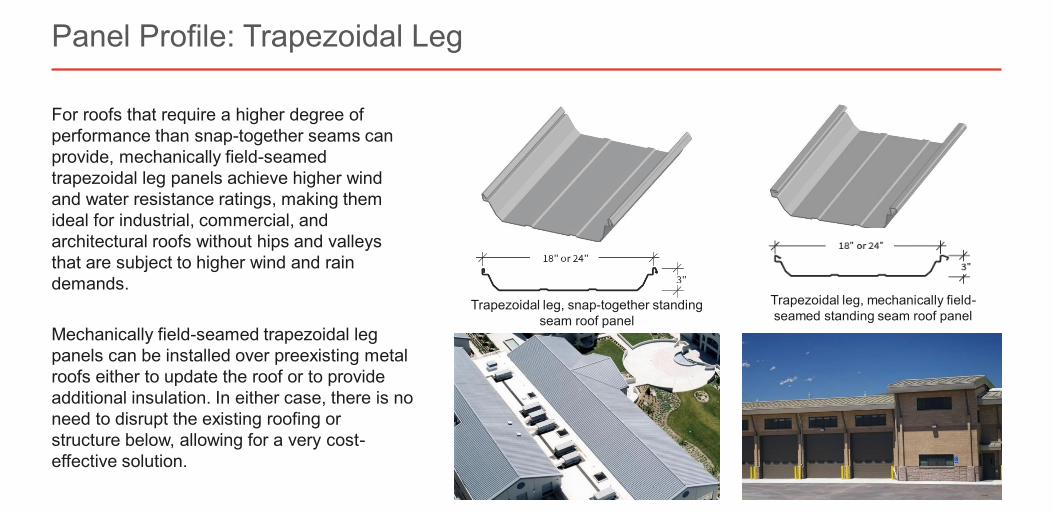
For roofs that require a higher degree of performance than snap-together seams can provide, mechanically field-seamed trapezoidal leg panels achieve higher wind and water resistance ratings, making them ideal for industrial, commercial, and architectural roofs without hips and valleys that are subject to higher wind and rain demands.
Mechanically field-seamed trapezoidal leg panels can be installed over preexisting metal roofs either to update the roof or to provide additional insulation. In either case, there is no need to disrupt the existing roofing or structure below, allowing for a very cost-effective solution.
Panel Profile: Trapezoidal Leg
Trapezoidal leg, mechanically field-seamed standing seam roof panel
Trapezoidal leg, snap-together standing seam roof panel
Slide 18 of 73©2021 ∙ Table of Contents < >
About the Instructor About the Sponsor Ask an Expert
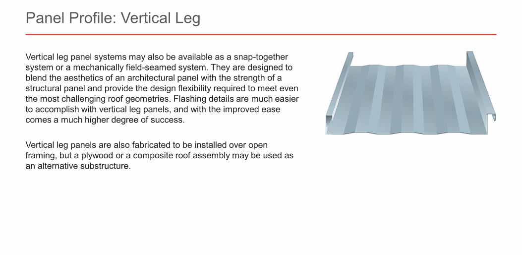
Vertical leg panel systems may also be available as a snap-together system or a mechanically field-seamed system. They are designed to blend the aesthetics of an architectural panel with the strength of a structural panel and provide the design flexibility required to meet even the most challenging roof geometries. Flashing details are much easier to accomplish with vertical leg panels, and with the improved ease comes a much higher degree of success.
Vertical leg panels are also fabricated to be installed over open framing, but a plywood or a composite roof assembly may be used as an alternative substructure.
Panel Profile: Vertical Leg
Slide 19 of 73©2021 ∙ Table of Contents < >
About the Instructor About the Sponsor Ask an Expert
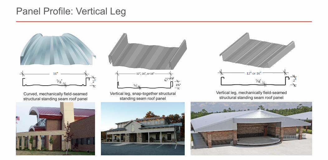
Panel Profile: Vertical Leg
Curved, mechanically field-seamed structural standing seam roof panel
Vertical leg, snap-together structural standing seam roof panel
Vertical leg, mechanically field-seamed structural standing seam roof panel
Slide 20 of 73©2021 ∙ Table of Contents < >
About the Instructor About the Sponsor Ask an Expert
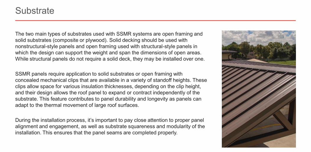
The two main types of substrates used with SSMR systems are open framing and solid substrates (composite or plywood). Solid decking should be used with nonstructural-style panels and open framing used with structural-style panels in which the design can support the weight and span the dimensions of open areas. While structural panels do not require a solid deck, they may be installed over one.
SSMR panels require application to solid substrates or open framing with concealed mechanical clips that are available in a variety of standoff heights. These clips allow space for various insulation thicknesses, depending on the clip height, and their design allows the roof panel to expand or contract independently of the substrate. This feature contributes to panel durability and longevity as panels can adapt to the thermal movement of large roof surfaces.
During the installation process, it’s important to pay close attention to proper panel alignment and engagement, as well as substrate squareness and modularity of the installation. This ensures that the panel seams are completed properly.
Substrate

Slide 21 of 73©2021 ∙ Table of Contents < >
About the Instructor About the Sponsor Ask an Expert
When an SSMR is specified, there is an expectation that it will perform as intended over the life of the building. This means the structural integrity of the panels/system is crucial given the various natural forces that can be imposed on the materials. Performance-based building product testing is usually very specific to an SSMR product based on protocols and procedures developed by independent agencies.
UL (Underwriters Laboratories) certifies roofing materials and roof assemblies for fire performance, hail resistance, and/or resistance to wind uplift. Roof deck assemblies are investigated for performance under internal fire exposures and for uplift resistance.
IAS (International Accreditation Service) criteria cover inspections of metal building system elements that are essential for designing, specifying, building, or approving metal building systems. They are based on recognized national and international standards to ensure that the building supplier’s engineering/order/design/fabrication processes all conform to high quality standards. IAS accreditation for metal building systems inspection is recognized by the Metal Building Manufacturers Association (MBMA) and the International Code Council (ICC).
FM Approvals (formerly known as Factory Mutual Laboratories) is well known for determining how roofing products and assemblies perform not only for fire but also for high wind and hail resistance.
A few of the industry standards considered most reliable for the design of SSMR panels are discussed later in the course.
Performance Requirements
Slide 22 of 73©2021 ∙ Table of Contents < >
About the Instructor About the Sponsor Ask an Expert
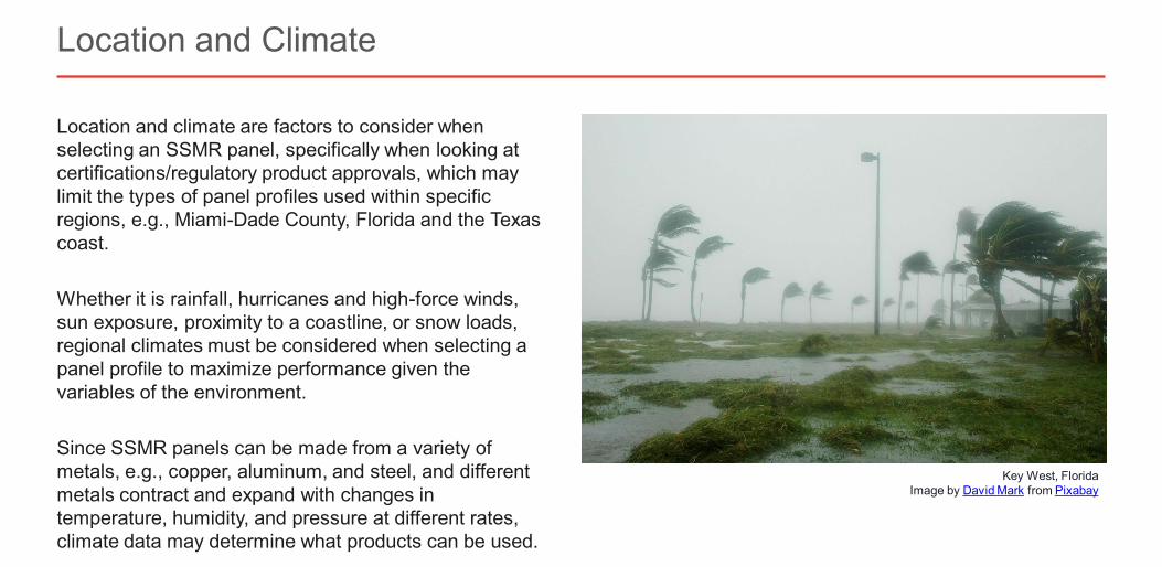
Location and climate are factors to consider when selecting an SSMR panel, specifically when looking at certifications/regulatory product approvals, which may limit the types of panel profiles used within specific regions, e.g., Miami-Dade County, Florida and the Texas coast.
Whether it is rainfall, hurricanes and high-force winds, sun exposure, proximity to a coastline, or snow loads, regional climates must be considered when selecting a panel profile to maximize performance given the variables of the environment.
Since SSMR panels can be made from a variety of metals, e.g., copper, aluminum, and steel, and different metals contract and expand with changes in temperature, humidity, and pressure at different rates, climate data may determine what products can be used.
Location and Climate
Key West, FloridaImage by David Mark from Pixabay
Slide 23 of 73©2021 ∙ Table of Contents < >
About the Instructor About the Sponsor Ask an Expert
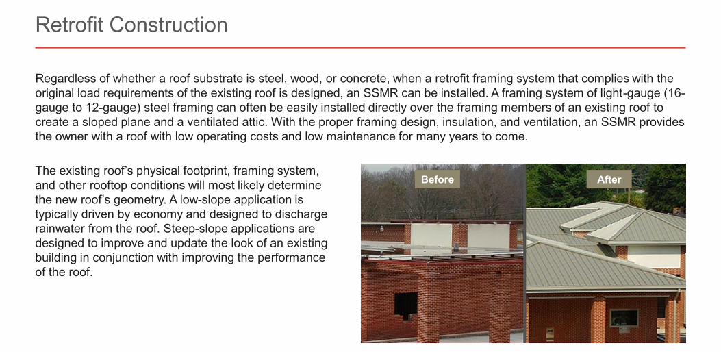
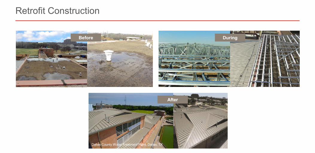
Regardless of whether a roof substrate is steel, wood, or concrete, when a retrofit framing system that complies with the original load requirements of the existing roof is designed, an SSMR can be installed. A framing system of light-gauge (16-gauge to 12-gauge) steel framing can often be easily installed directly over the framing members of an existing roof to create a sloped plane and a ventilated attic. With the proper framing design, insulation, and ventilation, an SSMR provides the owner with a roof with low operating costs and low maintenance for many years to come.
Retrofit Construction
The existing roof’s physical footprint, framing system, and other rooftop conditions will most likely determine the new roof’s geometry. A low-slope application is typically driven by economy and designed to discharge rainwater from the roof. Steep-slope applications are designed to improve and update the look of an existing building in conjunction with improving the performance of the roof.
Before After
Slide 24 of 73©2021 ∙ Table of Contents < >
About the Instructor About the Sponsor Ask an Expert
Retrofit Construction
Before During
After
Dallas County Water Treatment Plant, Dallas, TX
Slide 25 of 73©2021 ∙ Table of Contents < >
About the Instructor About the Sponsor Ask an Expert
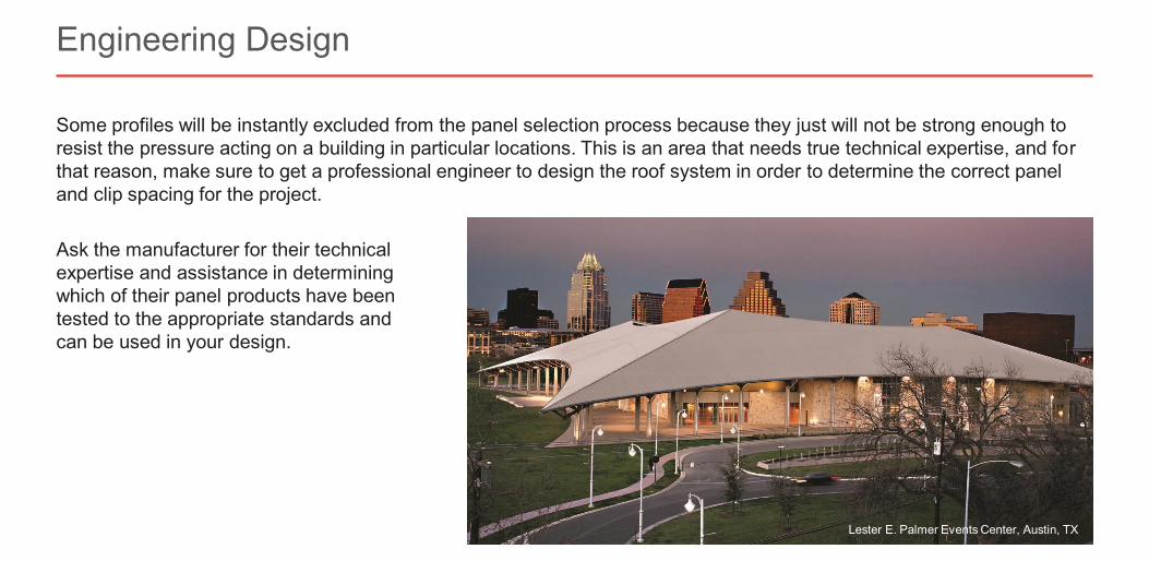
Some profiles will be instantly excluded from the panel selection process because they just will not be strong enough to resist the pressure acting on a building in particular locations. This is an area that needs true technical expertise, and for that reason, make sure to get a professional engineer to design the roof system in order to determine the correct panel and clip spacing for the project.
Ask the manufacturer for their technicalexpertise and assistance in determiningwhich of their panel products have beentested to the appropriate standards and can be used in your design.
Engineering Design
Lester E. Palmer Events Center, Austin, TX
Slide 26 of 73©2021 ∙ Table of Contents < >
About the Instructor About the Sponsor Ask an Expert
Specifying for Cold Climates
Slide 27 of 73©2021 ∙ Table of Contents < >
About the Instructor About the Sponsor Ask an Expert
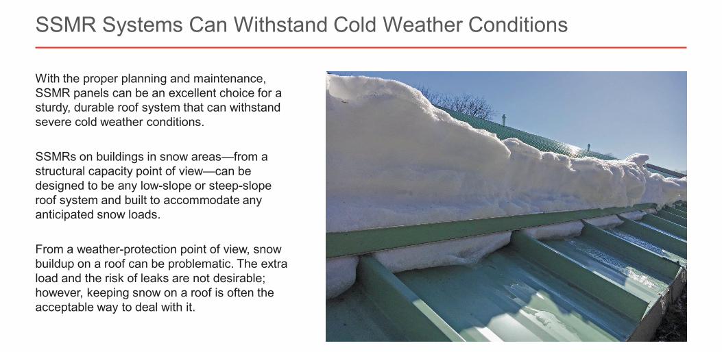
With the proper planning and maintenance, SSMR panels can be an excellent choice for a sturdy, durable roof system that can withstand severe cold weather conditions.
SSMRs on buildings in snow areas—from a structural capacity point of view—can be designed to be any low-slope or steep-slope roof system and built to accommodate any anticipated snow loads.
From a weather-protection point of view, snow buildup on a roof can be problematic. The extra load and the risk of leaks are not desirable; however, keeping snow on a roof is often the acceptable way to deal with it.
SSMR Systems Can Withstand Cold Weather Conditions
Slide 28 of 73©2021 ∙ Table of Contents < >
About the Instructor About the Sponsor Ask an Expert
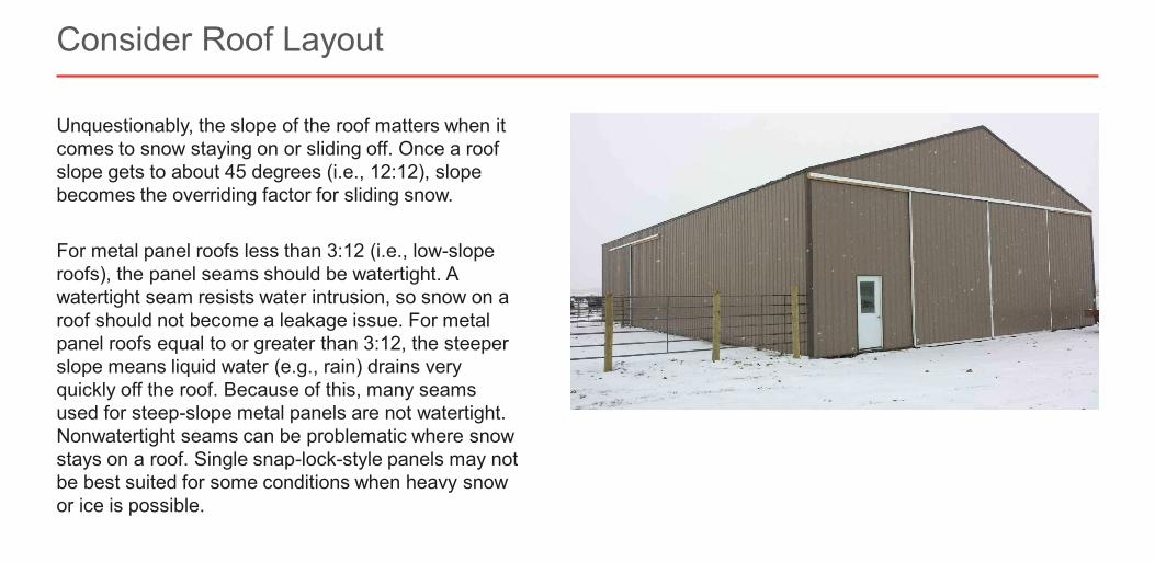
Unquestionably, the slope of the roof matters when it comes to snow staying on or sliding off. Once a roof slope gets to about 45 degrees (i.e., 12:12), slope becomes the overriding factor for sliding snow.
For metal panel roofs less than 3:12 (i.e., low-slope roofs), the panel seams should be watertight. A watertight seam resists water intrusion, so snow on a roof should not become a leakage issue. For metal panel roofs equal to or greater than 3:12, the steeper slope means liquid water (e.g., rain) drains very quickly off the roof. Because of this, many seams used for steep-slope metal panels are not watertight. Nonwatertight seams can be problematic where snow stays on a roof. Single snap-lock-style panels may not be best suited for some conditions when heavy snow or ice is possible.
Consider Roof Layout
Slide 29 of 73©2021 ∙ Table of Contents < >
About the Instructor About the Sponsor Ask an Expert
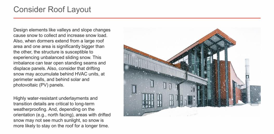
Design elements like valleys and slope changes cause snow to collect and increase snow load. Also, when dormers extend from a large roof area and one area is significantly bigger than the other, the structure is susceptible to experiencing unbalanced sliding snow. This imbalance can tear open standing seams and displace panels. Also, consider that drifting snow may accumulate behind HVAC units, at perimeter walls, and behind solar and photovoltaic (PV) panels.
Highly water-resistant underlayments and transition details are critical to long-term weatherproofing. And, depending on the orientation (e.g., north facing), areas with drifted snow may not see much sunlight, so snow is more likely to stay on the roof for a longer time.
Consider Roof Layout
Slide 30 of 73©2021 ∙ Table of Contents < >
About the Instructor About the Sponsor Ask an Expert
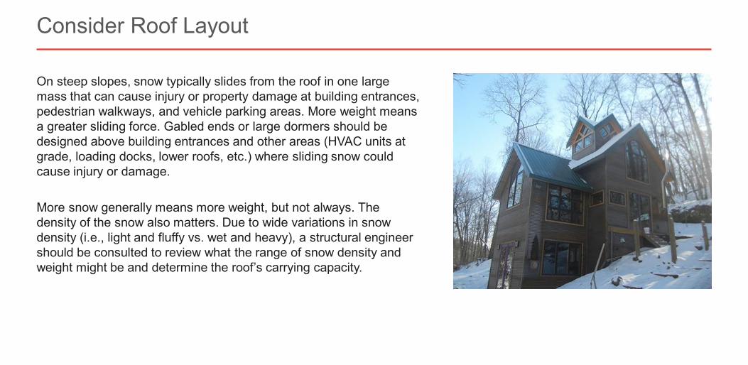
On steep slopes, snow typically slides from the roof in one large mass that can cause injury or property damage at building entrances, pedestrian walkways, and vehicle parking areas. More weight means a greater sliding force. Gabled ends or large dormers should be designed above building entrances and other areas (HVAC units at grade, loading docks, lower roofs, etc.) where sliding snow could cause injury or damage.
More snow generally means more weight, but not always. The density of the snow also matters. Due to wide variations in snow density (i.e., light and fluffy vs. wet and heavy), a structural engineer should be consulted to review what the range of snow density and weight might be and determine the roof’s carrying capacity.
Consider Roof Layout
Slide 31 of 73©2021 ∙ Table of Contents < >
About the Instructor About the Sponsor Ask an Expert
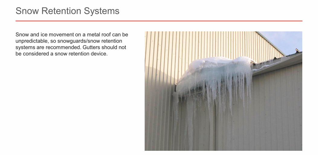
Snow and ice movement on a metal roof can be unpredictable, so snowguards/snow retention systems are recommended. Gutters should not be considered a snow retention device.
Snow Retention Systems
Slide 32 of 73©2021 ∙ Table of Contents < >
About the Instructor About the Sponsor Ask an Expert
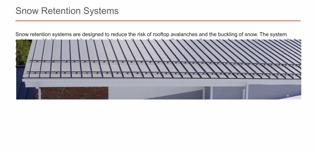
Snow retention systems are designed to reduce the risk of rooftop avalanches and the buckling of snow. The system catches and holds snow while allowing it to leave the roof slowly, either by small amounts of snow at a time or as melted snow or water. The systems are designed to be compatible with a manufacturer’s roof panels and must be properly engineered for a particular roof and snow load. System design considers not only the site-specific calculations for the loads to which the system will be exposed to but also the type and spacing of the clips, roof slope, panel run length, and other details.
Snow Retention Systems
Slide 33 of 73©2021 ∙ Table of Contents < >
About the Instructor About the Sponsor Ask an Expert
Testing and Performance Standards
Slide 34 of 73©2021 ∙ Table of Contents < >
About the Instructor About the Sponsor Ask an Expert
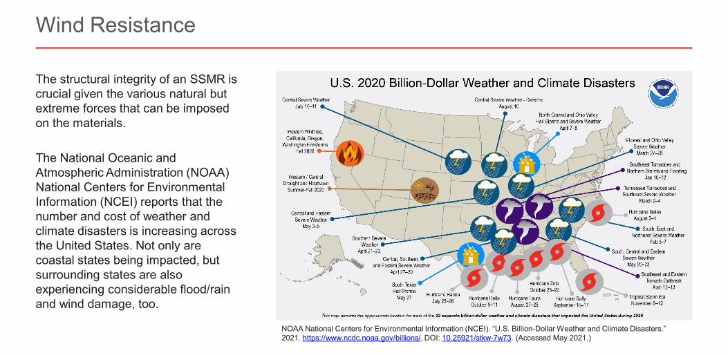
The structural integrity of an SSMR is crucial given the various natural but extreme forces that can be imposed on the materials.
The National Oceanic and Atmospheric Administration (NOAA) National Centers for Environmental Information (NCEI) reports that the number and cost of weather and climate disasters is increasing across the United States. Not only are coastal states being impacted, but surrounding states are also experiencing considerable flood/rain and wind damage, too.
Wind Resistance
NOAA National Centers for Environmental Information (NCEI). “U.S. Billion-Dollar Weather and Climate Disasters.” 2021. https://www.ncdc.noaa.gov/billions/, DOI: 10.25921/stkw-7w73. (Accessed May 2021.)
Slide 35 of 73©2021 ∙ Table of Contents < >
About the Instructor About the Sponsor Ask an Expert
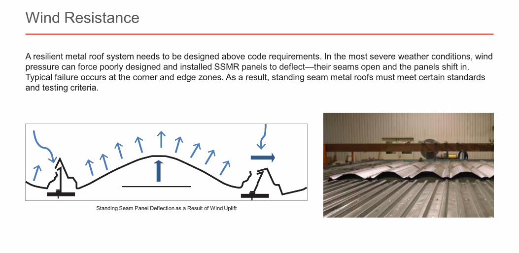
A resilient metal roof system needs to be designed above code requirements. In the most severe weather conditions, wind pressure can force poorly designed and installed SSMR panels to deflect—their seams open and the panels shift in. Typical failure occurs at the corner and edge zones. As a result, standing seam metal roofs must meet certain standards and testing criteria.
Wind Resistance
Standing Seam Panel Deflection as a Result of Wind Uplift
Slide 36 of 73©2021 ∙ Table of Contents < >
About the Instructor About the Sponsor Ask an Expert
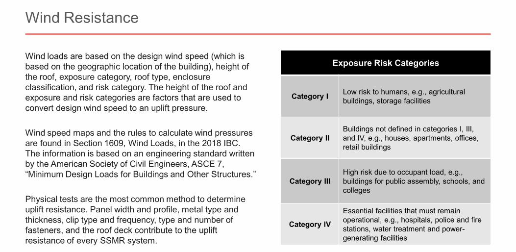
Wind loads are based on the design wind speed (which is based on the geographic location of the building), height of the roof, exposure category, roof type, enclosure classification, and risk category. The height of the roof and exposure and risk categories are factors that are used to convert design wind speed to an uplift pressure.
Wind speed maps and the rules to calculate wind pressures are found in Section 1609, Wind Loads, in the 2018 IBC. The information is based on an engineering standard written by the American Society of Civil Engineers, ASCE 7, “Minimum Design Loads for Buildings and Other Structures.”
Physical tests are the most common method to determine uplift resistance. Panel width and profile, metal type and thickness, clip type and frequency, type and number of fasteners, and the roof deck contribute to the uplift resistance of every SSMR system.
Wind Resistance
Exposure Risk Categories
Category I Low risk to humans, e.g., agricultural buildings, storage facilities
Category IIBuildings not defined in categories I, III, and IV, e.g., houses, apartments, offices, retail buildings
Category IIIHigh risk due to occupant load, e.g., buildings for public assembly, schools, and colleges
Category IV
Essential facilities that must remain operational, e.g., hospitals, police and fire stations, water treatment and power-generating facilities
Slide 37 of 73©2021 ∙ Table of Contents < >
About the Instructor About the Sponsor Ask an Expert
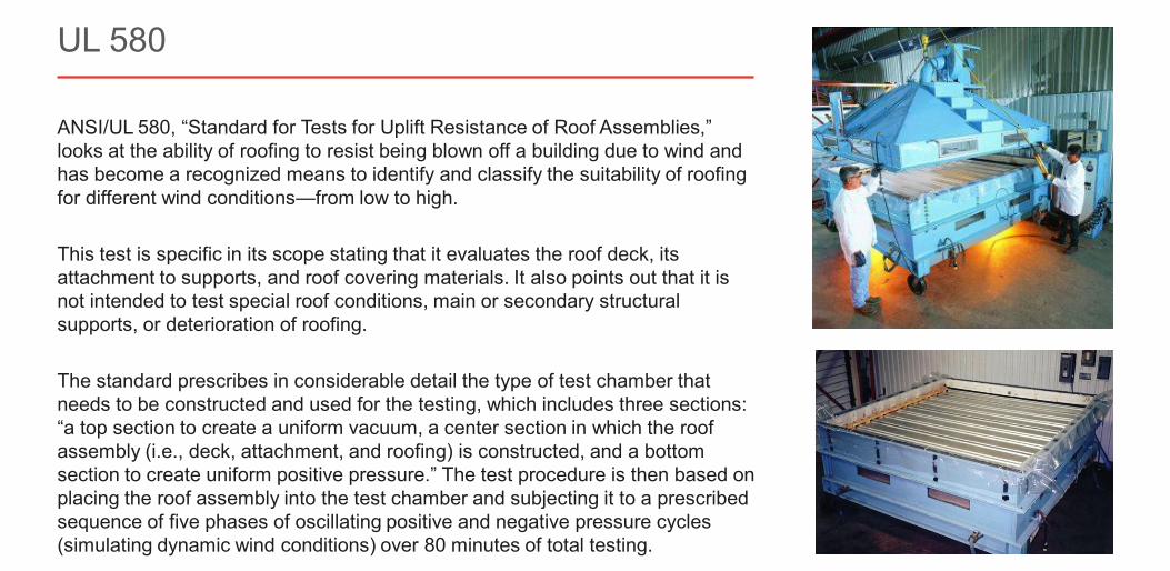
ANSI/UL 580, “Standard for Tests for Uplift Resistance of Roof Assemblies,” looks at the ability of roofing to resist being blown off a building due to wind and has become a recognized means to identify and classify the suitability of roofing for different wind conditions—from low to high.
This test is specific in its scope stating that it evaluates the roof deck, its attachment to supports, and roof covering materials. It also points out that it is not intended to test special roof conditions, main or secondary structural supports, or deterioration of roofing.
The standard prescribes in considerable detail the type of test chamber that needs to be constructed and used for the testing, which includes three sections: “a top section to create a uniform vacuum, a center section in which the roof assembly (i.e., deck, attachment, and roofing) is constructed, and a bottom section to create uniform positive pressure.” The test procedure is then based on placing the roof assembly into the test chamber and subjecting it to a prescribed sequence of five phases of oscillating positive and negative pressure cycles (simulating dynamic wind conditions) over 80 minutes of total testing.
UL 580
Slide 38 of 73©2021 ∙ Table of Contents < >
About the Instructor About the Sponsor Ask an Expert
It’s important to note that UL 580: • is a pass/fail test and does not specifically determine the wind resistance of a panel assembly• only tests over a specific substrate at a certain clip/fastener spacing, and• will not indicate how strong the panel assembly is under load.
There are three wind uplift classifications, Class 30, Class 60, and Class 90, obtainable for a tested assembly based on the test assembly retaining its attachment and integrity without any permanent damage. Each class has its own requirements for test pressures, with increasing pressure as the class number increases. Higher class numbers indicate increasing levels of wind uplift resistance. Note, the same assembly is tested throughout UL 580, so to obtain a higher class rating, the assembly being tested must pass each of the test sequences consecutively. If an assembly achieves a Class 90 rating, it can then be subjected to UL 1897.
UL 580
Slide 39 of 73©2021 ∙ Table of Contents < >
About the Instructor About the Sponsor Ask an Expert
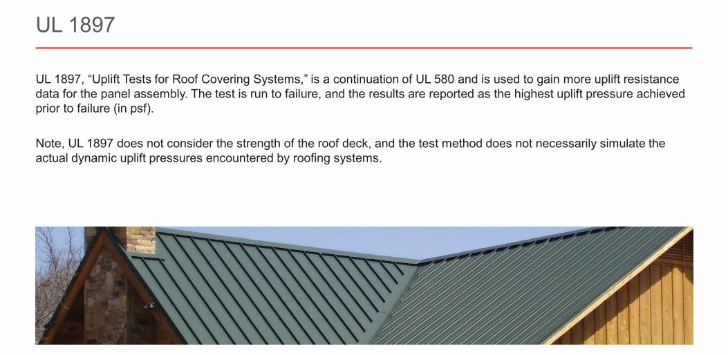
UL 1897, “Uplift Tests for Roof Covering Systems,” is a continuation of UL 580 and is used to gain more uplift resistance data for the panel assembly. The test is run to failure, and the results are reported as the highest uplift pressure achievedprior to failure (in psf).
Note, UL 1897 does not consider the strength of the roof deck, and the test method does not necessarily simulate the actual dynamic uplift pressures encountered by roofing systems.
UL 1897
Slide 40 of 73©2021 ∙ Table of Contents < >
About the Instructor About the Sponsor Ask an Expert
FM 4471, “Approval Standard for Class 1 Panel Roofs,” states the requirements for meeting the criteria for fire, wind, foot traffic, and hail damage resistance.
The test sets performance requirements for panel roofs, which include all components necessary for installation of the panel roof assembly. This includes the potential for fire spread on the underside and exterior of the roof panel. It also measures ability to resist simulated wind uplift while maintaining adequate strength and durability.
For roofing projects where FM insurance is required, project designers should work closely with the roofing manufacturer to ensure the roofing system complies with FM requirements.
FM 4471
Slide 41 of 73©2021 ∙ Table of Contents < >
About the Instructor About the Sponsor Ask an Expert
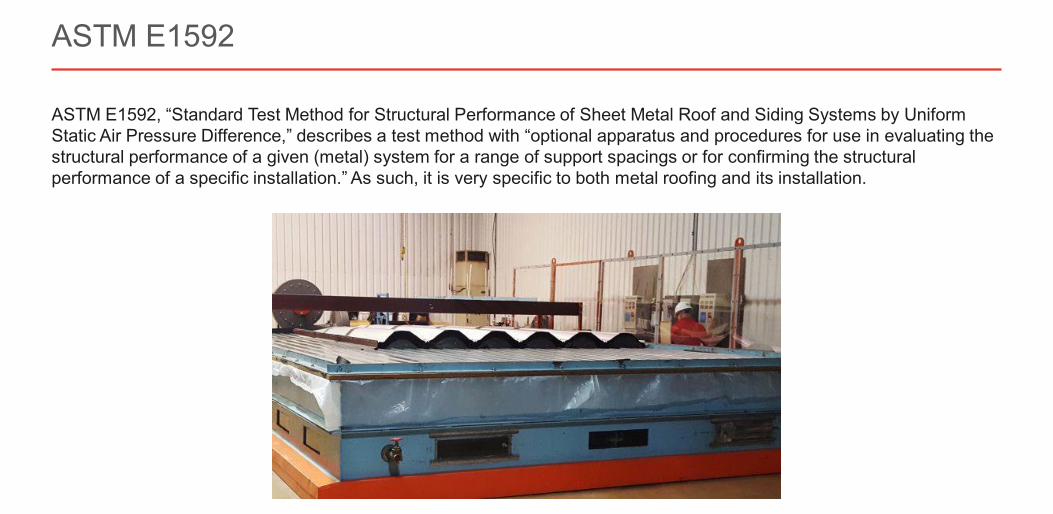
ASTM E1592, “Standard Test Method for Structural Performance of Sheet Metal Roof and Siding Systems by Uniform Static Air Pressure Difference,” describes a test method with “optional apparatus and procedures for use in evaluating the structural performance of a given (metal) system for a range of support spacings or for confirming the structural performance of a specific installation.” As such, it is very specific to both metal roofing and its installation.
ASTM E1592
Slide 42 of 73©2021 ∙ Table of Contents < >
About the Instructor About the Sponsor Ask an Expert
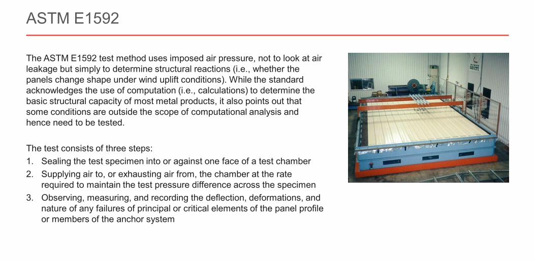
The ASTM E1592 test method uses imposed air pressure, not to look at air leakage but simply to determine structural reactions (i.e., whether the panels change shape under wind uplift conditions). While the standard acknowledges the use of computation (i.e., calculations) to determine the basic structural capacity of most metal products, it also points out that some conditions are outside the scope of computational analysis and hence need to be tested.
The test consists of three steps:1. Sealing the test specimen into or against one face of a test chamber2. Supplying air to, or exhausting air from, the chamber at the rate
required to maintain the test pressure difference across the specimen3. Observing, measuring, and recording the deflection, deformations, and
nature of any failures of principal or critical elements of the panel profileor members of the anchor system
ASTM E1592
Slide 43 of 73©2021 ∙ Table of Contents < >
About the Instructor About the Sponsor Ask an Expert
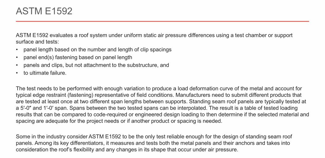
ASTM E1592 evaluates a roof system under uniform static air pressure differences using a test chamber or support surface and tests:• panel length based on the number and length of clip spacings• panel end(s) fastening based on panel length• panels and clips, but not attachment to the substructure, and• to ultimate failure.
The test needs to be performed with enough variation to produce a load deformation curve of the metal and account for typical edge restraint (fastening) representative of field conditions. Manufacturers need to submit different products that are tested at least once at two different span lengths between supports. Standing seam roof panels are typically tested at a 5′-0″ and 1′-0′ span. Spans between the two tested spans can be interpolated. The result is a table of tested loading results that can be compared to code-required or engineered design loading to then determine if the selected material and spacing are adequate for the project needs or if another product or spacing is needed.
Some in the industry consider ASTM E1592 to be the only test reliable enough for the design of standing seam roof panels. Among its key differentiators, it measures and tests both the metal panels and their anchors and takes into consideration the roof’s flexibility and any changes in its shape that occur under air pressure.
ASTM E1592
Slide 44 of 73©2021 ∙ Table of Contents < >
About the Instructor About the Sponsor Ask an Expert
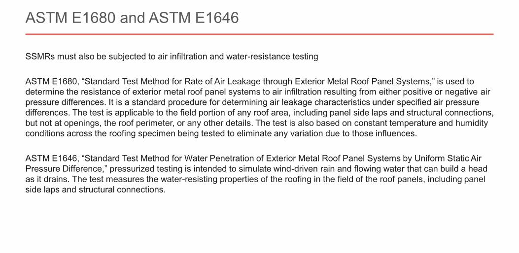
SSMRs must also be subjected to air infiltration and water-resistance testing
ASTM E1680, “Standard Test Method for Rate of Air Leakage through Exterior Metal Roof Panel Systems,” is used to determine the resistance of exterior metal roof panel systems to air infiltration resulting from either positive or negative airpressure differences. It is a standard procedure for determining air leakage characteristics under specified air pressure differences. The test is applicable to the field portion of any roof area, including panel side laps and structural connections,but not at openings, the roof perimeter, or any other details. The test is also based on constant temperature and humidity conditions across the roofing specimen being tested to eliminate any variation due to those influences.
ASTM E1646, “Standard Test Method for Water Penetration of Exterior Metal Roof Panel Systems by Uniform Static Air Pressure Difference,” pressurized testing is intended to simulate wind-driven rain and flowing water that can build a head as it drains. The test measures the water-resisting properties of the roofing in the field of the roof panels, including panel side laps and structural connections.
ASTM E1680 and ASTM E1646
Slide 45 of 73©2021 ∙ Table of Contents < >
About the Instructor About the Sponsor Ask an Expert
Best Practices for Detailing an SSMR
Owens Community College, Fredericktown, OH
Slide 46 of 73©2021 ∙ Table of Contents < >
About the Instructor About the Sponsor Ask an Expert
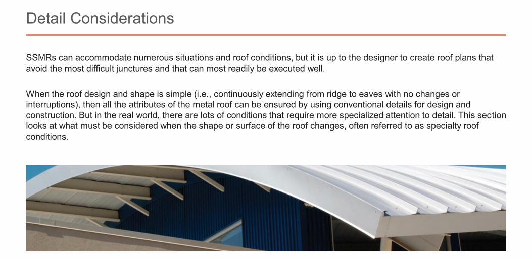
SSMRs can accommodate numerous situations and roof conditions, but it is up to the designer to create roof plans that avoid the most difficult junctures and that can most readily be executed well.
When the roof design and shape is simple (i.e., continuously extending from ridge to eaves with no changes or interruptions), then all the attributes of the metal roof can be ensured by using conventional details for design and construction. But in the real world, there are lots of conditions that require more specialized attention to detail. This section looks at what must be considered when the shape or surface of the roof changes, often referred to as specialty roof conditions.
Detail Considerations
Slide 47 of 73©2021 ∙ Table of Contents < >
About the Instructor About the Sponsor Ask an Expert
SSMR systems are built to move, designed to account for necessary—and often substantial—expansion and contraction due to fluctuating thermal conditions. In fact, for many builders, this fact is one of the main reasons SSMRs are such an attractive option. Even with this expectation baked into the mix, many contractors and installers may still make a wrong turn when tying the SSMR into adjacent structures and other building edge conditions. By not allowing for that same expansion and contraction on trims and transitions, problems can ensue.
One main consideration in planning for movement (both interior and exterior) caused by thermal changes is the clip type used. Panel clips connect the roof panels to the roof structure, so they need to be installed in a manner that allows them to do that job under normal and demanding circumstances. The driving issue is not keeping the panel down but preventing it from blowing off in a strong wind.
The clips, which are part of the concealed fastening system, are designed specifically to interact with their corresponding roof panels and to improve aesthetics in addition to durability and protection from the elements.
Build for Expansion and Contraction
Slide 48 of 73©2021 ∙ Table of Contents < >
About the Instructor About the Sponsor Ask an Expert
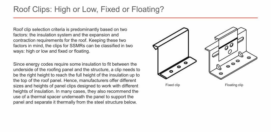
Roof clip selection criteria is predominantly based on two factors: the insulation system and the expansion and contraction requirements for the roof. Keeping these two factors in mind, the clips for SSMRs can be classified in two ways: high or low and fixed or floating.
Since energy codes require some insulation to fit between the underside of the roofing panel and the structure, a clip needs to be the right height to reach the full height of the insulation up to the top of the roof panel. Hence, manufacturers offer different sizes and heights of panel clips designed to work with different heights of insulation. In many cases, they also recommend the use of a thermal spacer underneath the panel to support the panel and separate it thermally from the steel structure below.
Roof Clips: High or Low, Fixed or Floating?
Floating clipFixed clip
Slide 49 of 73©2021 ∙ Table of Contents < >
About the Instructor About the Sponsor Ask an Expert
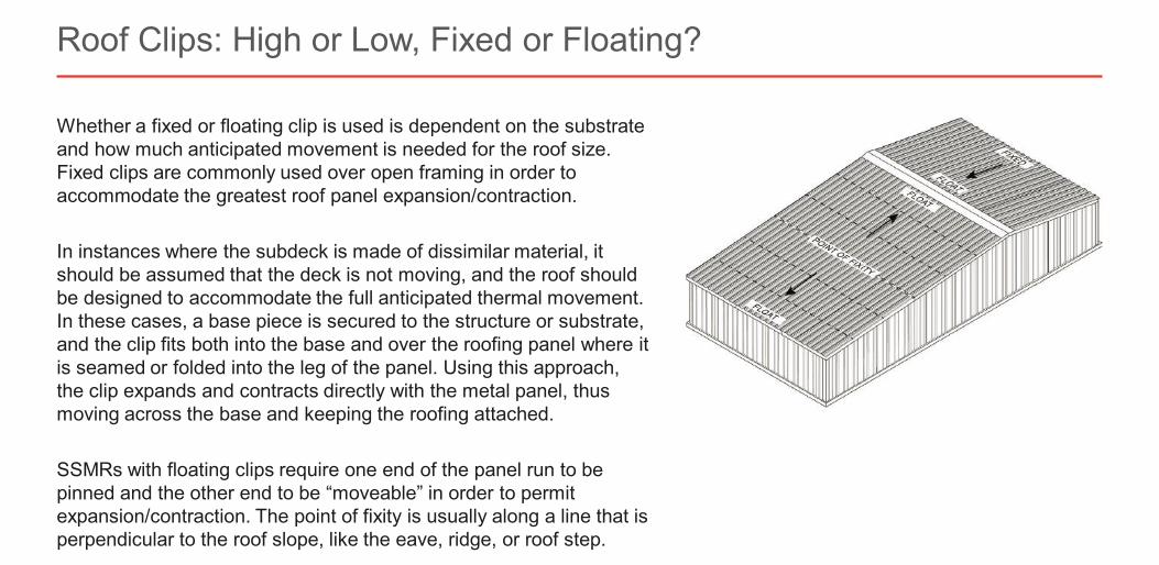
Whether a fixed or floating clip is used is dependent on the substrate and how much anticipated movement is needed for the roof size. Fixed clips are commonly used over open framing in order to accommodate the greatest roof panel expansion/contraction.
In instances where the subdeck is made of dissimilar material, it should be assumed that the deck is not moving, and the roof should be designed to accommodate the full anticipated thermal movement. In these cases, a base piece is secured to the structure or substrate, and the clip fits both into the base and over the roofing panel where it is seamed or folded into the leg of the panel. Using this approach, the clip expands and contracts directly with the metal panel, thus moving across the base and keeping the roofing attached.
SSMRs with floating clips require one end of the panel run to be pinned and the other end to be “moveable” in order to permit expansion/contraction. The point of fixity is usually along a line that is perpendicular to the roof slope, like the eave, ridge, or roof step.
Roof Clips: High or Low, Fixed or Floating?
Slide 50 of 73©2021 ∙ Table of Contents < >
About the Instructor About the Sponsor Ask an Expert
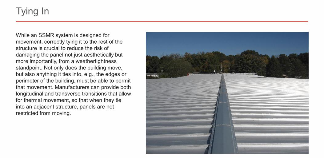
While an SSMR system is designed for movement, correctly tying it to the rest of the structure is crucial to reduce the risk of damaging the panel not just aesthetically but more importantly, from a weathertightness standpoint. Not only does the building move, but also anything it ties into, e.g., the edges or perimeter of the building, must be able to permit that movement. Manufacturers can provide both longitudinal and transverse transitions that allow for thermal movement, so that when they tie into an adjacent structure, panels are not restricted from moving.
Tying In
Slide 51 of 73©2021 ∙ Table of Contents < >
About the Instructor About the Sponsor Ask an Expert
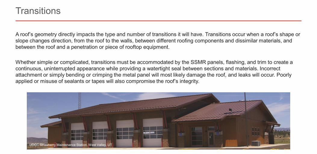
A roof’s geometry directly impacts the type and number of transitions it will have. Transitions occur when a roof’s shape or slope changes direction, from the roof to the walls, between different roofing components and dissimilar materials, and between the roof and a penetration or piece of rooftop equipment.
Whether simple or complicated, transitions must be accommodated by the SSMR panels, flashing, and trim to create a continuous, uninterrupted appearance while providing a watertight seal between sections and materials. Incorrect attachment or simply bending or crimping the metal panel will most likely damage the roof, and leaks will occur. Poorly applied or misuse of sealants or tapes will also compromise the roof’s integrity.
Transitions
UDOT Strawberry Maintenance Station, West Valley, UT
Slide 52 of 73©2021 ∙ Table of Contents < >
About the Instructor About the Sponsor Ask an Expert
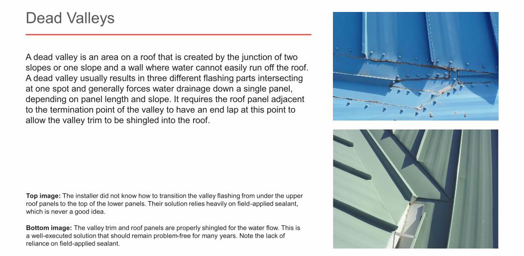
A dead valley is an area on a roof that is created by the junction of two slopes or one slope and a wall where water cannot easily run off the roof. A dead valley usually results in three different flashing parts intersecting at one spot and generally forces water drainage down a single panel, depending on panel length and slope. It requires the roof panel adjacent to the termination point of the valley to have an end lap at this point to allow the valley trim to be shingled into the roof.
Dead Valleys
Bottom image: The valley trim and roof panels are properly shingled for the water flow. This is a well-executed solution that should remain problem-free for many years. Note the lack of reliance on field-applied sealant.
Top image: The installer did not know how to transition the valley flashing from under the upper roof panels to the top of the lower panels. Their solution relies heavily on field-applied sealant, which is never a good idea.
Slide 53 of 73©2021 ∙ Table of Contents < >
About the Instructor About the Sponsor Ask an Expert
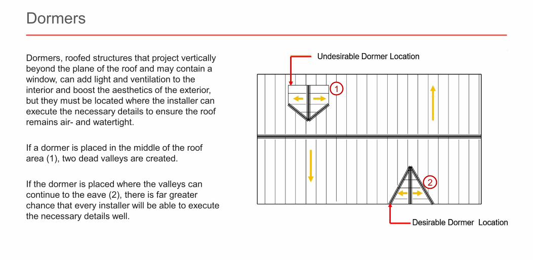
Dormers, roofed structures that project vertically beyond the plane of the roof and may contain a window, can add light and ventilation to the interior and boost the aesthetics of the exterior, but they must be located where the installer can execute the necessary details to ensure the roof remains air- and watertight.
If a dormer is placed in the middle of the roof area (1), two dead valleys are created.
If the dormer is placed where the valleys can continue to the eave (2), there is far greater chance that every installer will be able to execute the necessary details well.
Dormers
1
2
Slide 54 of 73©2021 ∙ Table of Contents < >
About the Instructor About the Sponsor Ask an Expert
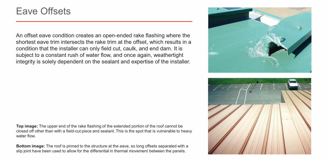
An offset eave condition creates an open-ended rake flashing where the shortest eave trim intersects the rake trim at the offset, which results in a condition that the installer can only field cut, caulk, and end dam. It is subject to a constant rush of water flow, and once again, weathertight integrity is solely dependent on the sealant and expertise of the installer.
Eave Offsets
Bottom image: The roof is pinned to the structure at the eave, so long offsets separated with a slip joint have been used to allow for the differential in thermal movement between the panels.
Top image: The upper end of the rake flashing of the extended portion of the roof cannot be closed off other than with a field-cut piece and sealant. This is the spot that is vulnerable to heavy water flow.
Slide 55 of 73©2021 ∙ Table of Contents < >
About the Instructor About the Sponsor Ask an Expert
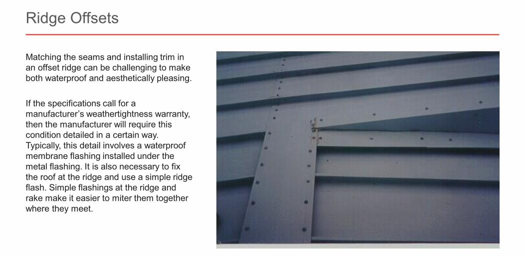
Matching the seams and installing trim in an offset ridge can be challenging to make both waterproof and aesthetically pleasing.
If the specifications call for a manufacturer’s weathertightness warranty, then the manufacturer will require this condition detailed in a certain way. Typically, this detail involves a waterproof membrane flashing installed under the metal flashing. It is also necessary to fix the roof at the ridge and use a simple ridge flash. Simple flashings at the ridge and rake make it easier to miter them together where they meet.
Ridge Offsets
Slide 56 of 73©2021 ∙ Table of Contents < >
About the Instructor About the Sponsor Ask an Expert
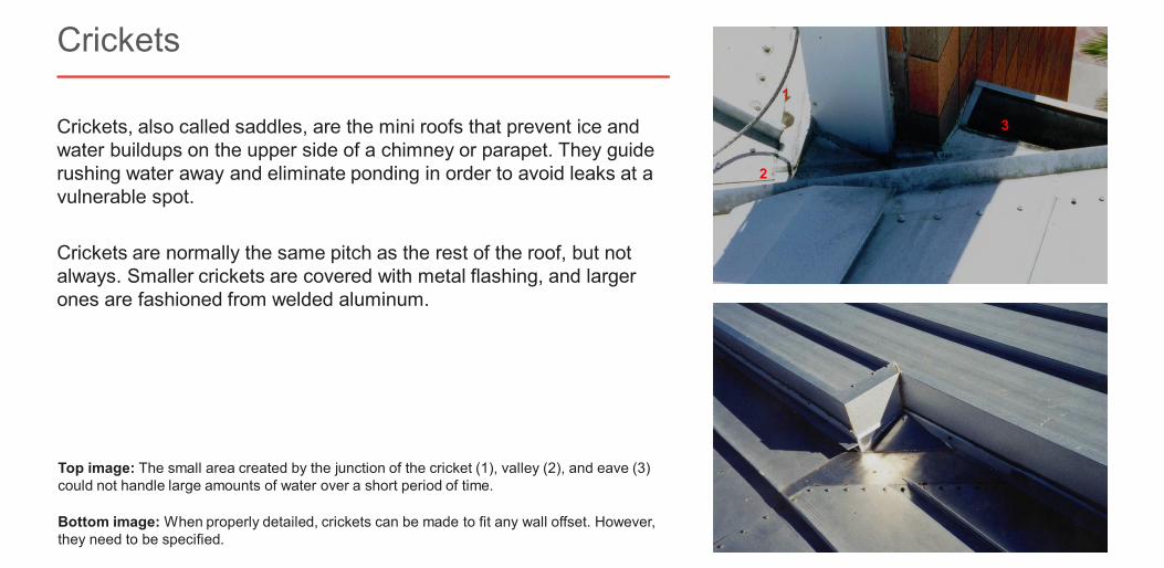
Crickets, also called saddles, are the mini roofs that prevent ice and water buildups on the upper side of a chimney or parapet. They guide rushing water away and eliminate ponding in order to avoid leaks at a vulnerable spot.
Crickets are normally the same pitch as the rest of the roof, but not always. Smaller crickets are covered with metal flashing, and larger ones are fashioned from welded aluminum.
Crickets
Bottom image: When properly detailed, crickets can be made to fit any wall offset. However, they need to be specified.
Top image: The small area created by the junction of the cricket (1), valley (2), and eave (3) could not handle large amounts of water over a short period of time.
Slide 57 of 73©2021 ∙ Table of Contents < >
About the Instructor About the Sponsor Ask an Expert
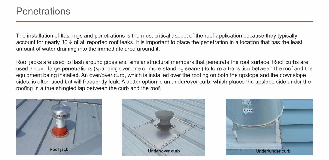
The installation of flashings and penetrations is the most critical aspect of the roof application because they typically account for nearly 80% of all reported roof leaks. It is important to place the penetration in a location that has the least amount of water draining into the immediate area around it.
Roof jacks are used to flash around pipes and similar structural members that penetrate the roof surface. Roof curbs are used around large penetrations (spanning over one or more standing seams) to form a transition between the roof and the equipment being installed. An over/over curb, which is installed over the roofing on both the upslope and the downslope sides, is often used but will frequently leak. A better option is an under/over curb, which places the upslope side under theroofing in a true shingled lap between the curb and the roof.
Penetrations
Under/under curbUnder/over curbRoof jack
Slide 58 of 73©2021 ∙ Table of Contents < >
About the Instructor About the Sponsor Ask an Expert
Penetrations
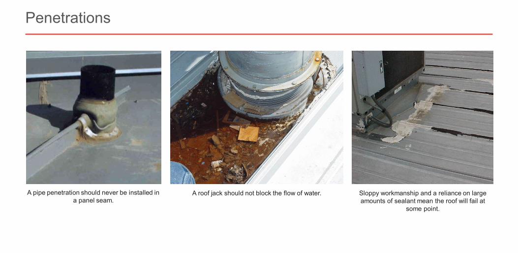
A pipe penetration should never be installed in a panel seam.
A roof jack should not block the flow of water. Sloppy workmanship and a reliance on large amounts of sealant mean the roof will fail at
some point.
Slide 59 of 73©2021 ∙ Table of Contents < >
About the Instructor About the Sponsor Ask an Expert
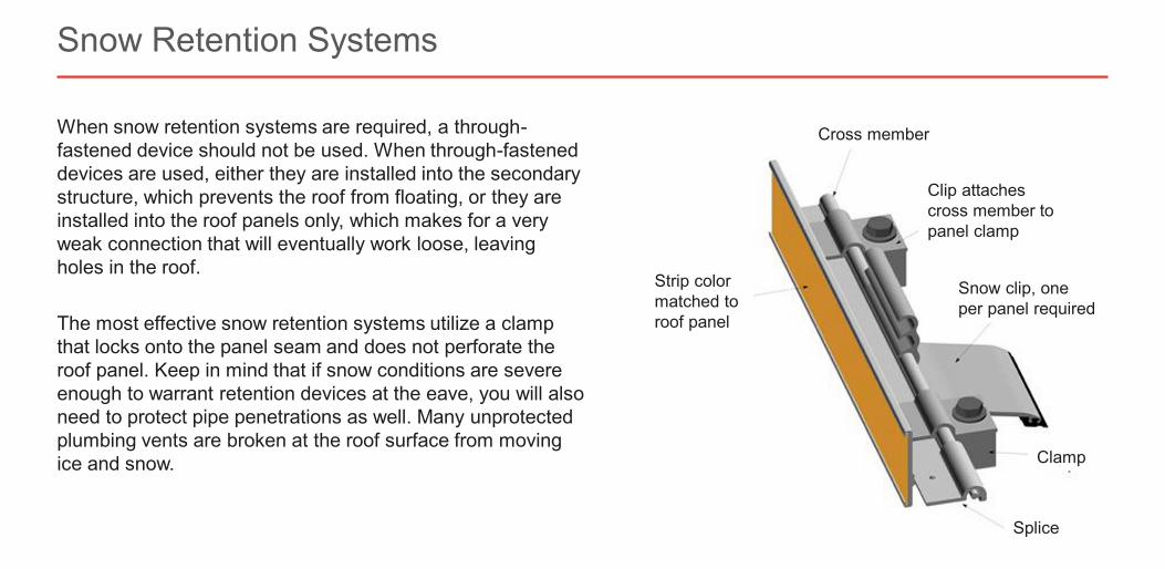
When snow retention systems are required, a through-fastened device should not be used. When through-fastened devices are used, either they are installed into the secondary structure, which prevents the roof from floating, or they are installed into the roof panels only, which makes for a very weak connection that will eventually work loose, leaving holes in the roof.
The most effective snow retention systems utilize a clamp that locks onto the panel seam and does not perforate the roof panel. Keep in mind that if snow conditions are severe enough to warrant retention devices at the eave, you will also need to protect pipe penetrations as well. Many unprotected plumbing vents are broken at the roof surface from moving ice and snow.
Snow Retention Systems
Clip attaches cross member to panel clamp
Snow clip, one per panel required
Strip color matched to roof panel
Clamp
Splice
Cross member
Slide 60 of 73©2021 ∙ Table of Contents < >
About the Instructor About the Sponsor Ask an Expert
Potential Installation Challenges
Conroe Fire Station No. 4, Conroe, TX
Slide 61 of 73©2021 ∙ Table of Contents < >
About the Instructor About the Sponsor Ask an Expert
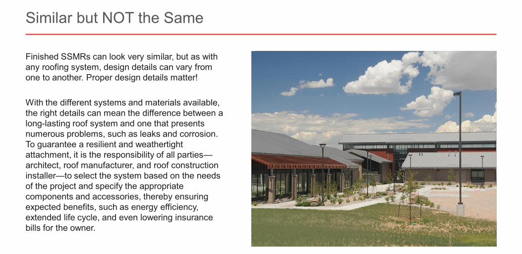
Finished SSMRs can look very similar, but as with any roofing system, design details can vary from one to another. Proper design details matter!
With the different systems and materials available, the right details can mean the difference between a long-lasting roof system and one that presents numerous problems, such as leaks and corrosion. To guarantee a resilient and weathertight attachment, it is the responsibility of all parties—architect, roof manufacturer, and roof construction installer—to select the system based on the needs of the project and specify the appropriate components and accessories, thereby ensuring expected benefits, such as energy efficiency, extended life cycle, and even lowering insurance bills for the owner.
Similar but NOT the Same
Slide 62 of 73©2021 ∙ Table of Contents < >
About the Instructor About the Sponsor Ask an Expert
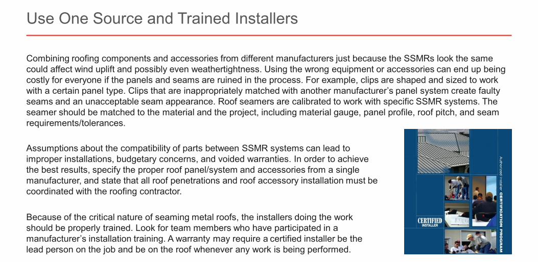
Combining roofing components and accessories from different manufacturers just because the SSMRs look the same could affect wind uplift and possibly even weathertightness. Using the wrong equipment or accessories can end up being costly for everyone if the panels and seams are ruined in the process. For example, clips are shaped and sized to work with a certain panel type. Clips that are inappropriately matched with another manufacturer’s panel system create faulty seams and an unacceptable seam appearance. Roof seamers are calibrated to work with specific SSMR systems. The seamer should be matched to the material and the project, including material gauge, panel profile, roof pitch, and seam requirements/tolerances.
Use One Source and Trained Installers
Assumptions about the compatibility of parts between SSMR systems can lead to improper installations, budgetary concerns, and voided warranties. In order to achieve the best results, specify the proper roof panel/system and accessories from a single manufacturer, and state that all roof penetrations and roof accessory installation must be coordinated with the roofing contractor.
Because of the critical nature of seaming metal roofs, the installers doing the work should be properly trained. Look for team members who have participated in a manufacturer’s installation training. A warranty may require a certified installer be the lead person on the job and be on the roof whenever any work is being performed.
Slide 63 of 73©2021 ∙ Table of Contents < >
About the Instructor About the Sponsor Ask an Expert
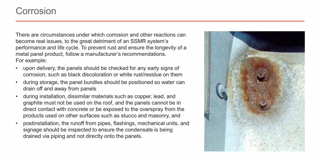
There are circumstances under which corrosion and other reactions can become real issues, to the great detriment of an SSMR system’s performance and life cycle. To prevent rust and ensure the longevity of a metal panel product, follow a manufacturer’s recommendations. For example:• upon delivery, the panels should be checked for any early signs of
corrosion, such as black discoloration or white rust/residue on them• during storage, the panel bundles should be positioned so water can
drain off and away from panels• during installation, dissimilar materials such as copper, lead, and
graphite must not be used on the roof, and the panels cannot be in direct contact with concrete or be exposed to the overspray from the products used on other surfaces such as stucco and masonry, and
• postinstallation, the runoff from pipes, flashings, mechanical units, and signage should be inspected to ensure the condensate is being drained via piping and not directly onto the panels.
Corrosion
Slide 64 of 73©2021 ∙ Table of Contents < >
About the Instructor About the Sponsor Ask an Expert
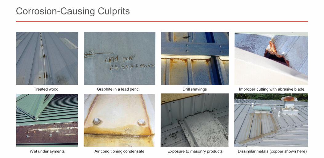
Corrosion-Causing Culprits
Drill shavings Improper cutting with abrasive bladeGraphite in a lead pencil
Exposure to masonry products
Treated wood
Air conditioning condensate Dissimilar metals (copper shown here) Wet underlayments
Slide 65 of 73©2021 ∙ Table of Contents < >
About the Instructor About the Sponsor Ask an Expert
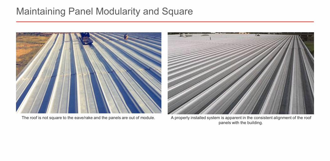
Most metal roofing system installers know the importance of keeping panels on module, i.e., holding the width of the panel, but holding module alone isn’t enough; keeping panels square is equally important, as the two go hand in hand. When proper attention is paid to both, the installation will be faster, the panels can expand and contract as designed, and the roof will look as intended.
The roof panel is not going to “hold itself” 100% on module and square by installing just as received using only the hardware components supplied from the manufacturer. The ability to hold panel modularity is directly dependent upon several factors: skillset of the installer, frequency that modularity is checked, substrate deficiencies, insulation system, appropriate methods being used to hold panel modularity during panel installation, and keeping symmetry/maintaining squareness.
Installers should check module/square every three to four panels. If the panel grows or shrinks 1/8″ or 3/16″ with three or four panels or shows signs of being out of square, there’s time to recover from it by making adjustments to correct. If an installer just blindly puts the roof on for 50 feet or so and then realizes they’re off module or out of square, it will likely be past the point of return to hold module and keep square.
Maintaining Panel Modularity and Square
Slide 66 of 73©2021 ∙ Table of Contents < >
About the Instructor About the Sponsor Ask an Expert
Maintaining Panel Modularity and Square
The roof is not square to the eave/rake and the panels are out of module. A properly installed system is apparent in the consistent alignment of the roof panels with the building.
Slide 67 of 73©2021 ∙ Table of Contents < >
About the Instructor About the Sponsor Ask an Expert
Roofing conditions that require a specialized attention to detail are created by an interruption or change in the shape or surface of the roof. These details have the potential to be a source of water leakage or heavy snow accumulation, or they may lead to conditions such as water cascading over an edge. If these special conditions are not identified and the proper planning and preparation steps not addressed, the roof and the building may be damaged.
The key to success is found in the fundamental principles of properly overlapping (i.e., “shingling”) all materials to allow water to drain smoothly away where it is intended without getting diverted to places where it shouldn’t go. This means the metal roofing panels need to be cut, fit, and installed properly, but it also means that flashing, sealants, and fasteners need to be installed correctly too, all regardless of the slope of the roof. For example: when a dead valley occurs because a gable roofed dormer is installed in the main area of a roof, multiple layers of materials are involved in the transition around the dormer, all of which need to be installed in the proper location, following the proper sequence, and with the proper connections.
Special Conditions
Please remember the test password PREVENT. You will be required to enter it in order to proceed with the online test.
Slide 68 of 73©2021 ∙ Table of Contents < >
About the Instructor About the Sponsor Ask an Expert
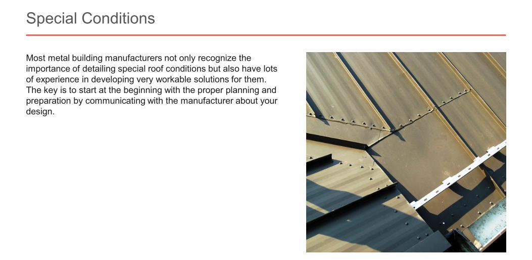
Most metal building manufacturers not only recognize the importance of detailing special roof conditions but also have lots of experience in developing very workable solutions for them. The key is to start at the beginning with the proper planning and preparation by communicating with the manufacturer about your design.
Special Conditions
Slide 69 of 73©2021 ∙ Table of Contents < >
About the Instructor About the Sponsor Ask an Expert
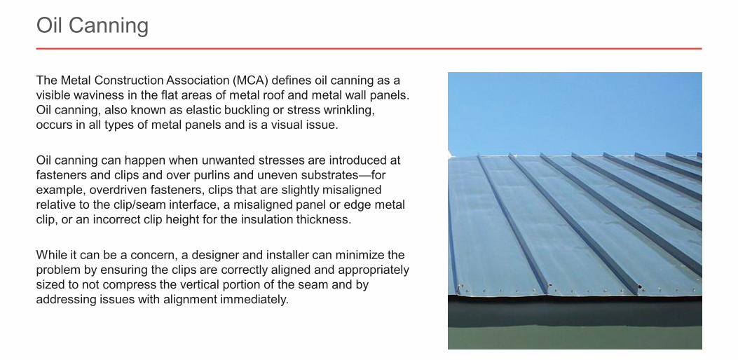
The Metal Construction Association (MCA) defines oil canning as a visible waviness in the flat areas of metal roof and metal wall panels. Oil canning, also known as elastic buckling or stress wrinkling, occurs in all types of metal panels and is a visual issue.
Oil canning can happen when unwanted stresses are introduced at fasteners and clips and over purlins and uneven substrates—for example, overdriven fasteners, clips that are slightly misaligned relative to the clip/seam interface, a misaligned panel or edge metal clip, or an incorrect clip height for the insulation thickness.
While it can be a concern, a designer and installer can minimize the problem by ensuring the clips are correctly aligned and appropriately sized to not compress the vertical portion of the seam and by addressing issues with alignment immediately.
Oil Canning
Slide 70 of 73©2021 ∙ Table of Contents < >
About the Instructor About the Sponsor Ask an Expert
Summary and Resources
Country Inn & Suites, Adel, GA
Slide 71 of 73©2021 ∙ Table of Contents < >
About the Instructor About the Sponsor Ask an Expert
Standing seam metal roofs (SSMRS) are system designs. All the pieces must work together in complete harmony to have a successful outcome.
Selecting the right SSMR panel for a project requires looking at all the determining factors (e.g., roof slope and geometry, location and climate, panel profile, type of construction) and narrowing down the choices based on the project variables. Once you’ve eliminated the panels that surely won’t work, you will still likely be left with many strong choices. Consult themanufacturer and review a panel’s test results (e.g., ASTM E1592, UL 580) to ensure it meets the performance criteria for the application and location.
SSMRs, with their durability and flexibility, are often deemed to be the ideal choice when the need to accommodate thermal contraction and expansion caused by temperature fluctuations is an issue. Every panel has its own roof clips, so the roof clips are not interchangeable across all systems. An essential part of selecting a roof panel is verifying that its clip attachment is suitable for your project.
The detailing of an SSMR is critical as most leaks occur at junctions, penetrations, and edges and not in the field of the roof itself. It is critical to designers, owners, and contractors that the details for problem areas be created and installedaccording to a manufacturer’s instructions and that the manufacturer be consulted during the detailing phase.
Summary
Slide 72 of 73©2021 ∙ Table of Contents < >
About the Instructor About the Sponsor Ask an Expert
Buchinger, Ken. “Getting the Most from Your Metal Roof.” Metal Architecture. Modern Trade Communications Inc., April 30, 2014, https://www.metalarchitecture.com/articles/getting-the-most-from-your-metal-roof. Accessed March 2021.
Marro, Marcy. “Testing for Wind Uplift.” Metal Construction News. Modern Trade Communications Inc., June 3, 2019, https://www.metalconstructionnews.com/articles/testing-for-wind-uplift. Accessed March 2021.
“Metal Construction Association Roof Seaming Best Practices Guide.” Metal Construction Association, September 2015, https://www.metalconstruction.org/view/download.php/online-education/education-materials/roofing-educational-materials/roof-seaming-best-practices-guide. Accessed May 2021.
“Metal Roof Design for Cold Climates.” Metal Construction Association, October 2019, https://www.metalconstruction.org/view/download.php/online-education/education-materials/roofing-educational-materials/metal-roof-design-for-cold-climates. Accessed May 2021.
“Metal Roof Installation Manual.” Metal Construction Association, n.d., https://metalconstruction.org/index.php/online-education/metal-roof-installation-manual. Accessed May 2021.
“Oil Canning in Metal Roof and Metal Wall Systems.” Metal Construction Association, April 2018, https://www.metalconstruction.org/view/download.php/online-education/education-materials/other-educational-files/oil-canning-in-metal-roof-and-metal-wall-systems. Accessed May 2021.
Robins, Mark. “The FAQs of Standing Seam Panel Clips.” Metal Construction News. Modern Trade Communications Inc., July 4, 2017, https://www.metalconstructionnews.com/articles/the-faqs-of-standing-seam-panel-clips. Accessed May 2021.
---. “Solving Challenging Flashing Applications.” Metal Construction News. Modern Trade Communications Inc., January 30, 2017, https://www.metalconstructionnews.com/articles/solving-challenging-flashing-applications. Accessed May 2021.
“Standing Seam Roof Clips Best Practices Guide.” Metal Construction Association, September 2017, https://www.metalconstruction.org/view/download.php/online-education/education-materials/roofing-educational-materials/standing-seam-roof-clips. Accessed May 2021.
Additional Resources


![STRUCTURAL STANDING SEAM ROOF SYSTEMS...2 16 or 18" [406mm or 457mm] 3 " Exterior [32mm] [7 6 m m] PANELS SRS Standing Seam Roof System panels, battens, flashings and closures are](https://img.pdfslide.us/doc/110x75/5e8c65c2ba3d737ddc66779d/structural-standing-seam-roof-systems-2-16-or-18-406mm-or-457mm-3-.jpg)