Embed Size (px)
Citation preview


Designing Simple Hydraulic Joints
Gui Cavalcanti
6/10/2012

Overview
• Designing a joint made from a pivot and a
hydraulic piston from scratch can be confusing,
given the near-infinite design options
• Characterizing such a joint for range of motion,
torque, and flow while having infinite design
options can be even more confusing
• In this presentation, my goal is to convey a
simple, quantitative method to design single-
pivot hydraulic joints

Example Joint
Let’s take the elbow joint of an earthmover
and use it to generate common terminology.

Example Joint

Example Joint

Example Joint
For the moment, let’s only care about the
cylinder, the joint it’s driving, and where it’s
mounted relative to the joint it’s driving.

Example Joint

Example Joint
Now, let’s define some terminology.

Example Joint
Joint Pivot
Static Anchor
Dynamic Anchor
Static Anchor
Radius
Cylinder
Length
Dynamic
Anchor Radius

Example Joint
Let’s add one more dimension, whose
purpose may not be immediately obvious.

Example Joint
Joint Pivot
Static Anchor
Dynamic Anchor
Static Anchor
Length
Cylinder
Length
Dynamic
Anchor Length
Moment Arm

Example Joint
Linear Piston Force * Moment Arm = Torque @ Joint
Moment Arm
Joint Pivot

Example Joint
Now that we have terminology, let’s start
designing.

Joint Design
1. Determine joint range of motion (ROM), minimum
desired torques, and directions of torque
2. Determine if there are any constraints on where the
dynamic and static anchor must be placed due to the
rest of your design
3. Select an appropriate piston bore, rod size, and
moment arm based on requirements
4. Choose an initial piston length to evaluate
5. Create constraining sketches
6. Iterate on hydraulic cylinder length until moment arm
relationships are satisfied; iterate bore if necessary

1. Joint Characterization
1. How large of a sweep (less than ~120
degrees) do you want?
2. What maximum/minimum torque is
required at the joint, at which position?
3. What direction is that torque in?

Joint Characterization Example:
Extended Stompy Leg
Maximum hip pitch torque required for Stompy:
100” * 1,000 lb (1/3 of tripod gait) = 100,000 in*lb
100,000 in*lb * 1.2 Factor of Safety = 120,000 in*lb
61”
84”
100”
1,000 lb

2. Determine Position Constraints
1. Will the dynamic anchor or
the static anchor be closer
to the joint?
– Static anchor closer:
traditional pitch joint
placement on excavators
– Dynamic anchor closer:
traditional elbow joint
placement on excavators

Position Constraint Example:
Extended Stompy Leg
Since we’re creating miniature excavator
legs, let’s keep the static anchor closer to
the driven joint
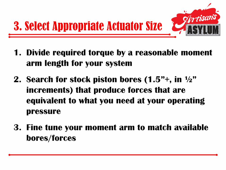
3. Select Appropriate Actuator Size
1. Divide required torque by a reasonable moment
arm length for your system
2. Search for stock piston bores (1.5”+, in ½”
increments) that produce forces that are
equivalent to what you need at your operating
pressure
3. Fine tune your moment arm to match available
bores/forces

Appropriate Actuator Example:
Extended Stompy Leg
1. 6” seems like a reasonable moment arm;
120,000 in*lb / 6 in = 20,000 lb
2. 3” bore @ 2500 psi = 17,670 lb
3. 120,000 in*lb / 17,670 lb = 6.8”
moment arm

4. Choose An Example Piston
1. Choose a moderate length piston to experiment
with in a sketching or 3D modeling program

Choose An Example Piston:
Extended Stompy Leg
1. Choose an 8” length, 3” bore piston:
– Prince A300080ABAA07B
– 3” bore, 8” stroke, 1.375” rod
– Retracted length: 20.25”
– Extended Length: 28.25”
5. Create Constraining Sketches
1. Draw an initial triangle between the driven joint, the static
anchor, and the dynamic anchor, using the retracted length
2. From the same joint position and static anchor position,
draw a new triangle to a second dynamic anchor, using the
extended length
3. Equate the two dynamic anchor radii to themselves
4. Constrain the two dynamic anchor radii with the desired
range of motion
5. Draw in the moment arm on the appropriate triangle to fully
constrain the sketch

Create Constraining Sketches:
Extended Stompy Leg

Create Constraining Sketches:
Extended Stompy Leg

Create Constraining Sketches:
Extended Stompy Leg
Note that by enforcing a 6.8” moment arm at one
end of the stroke, there is almost no moment arm
(i.e., we’re at a singularity) at the other end of the
stroke. Thus, we need a longer piston, or we’ll get
trapped in that position.

Choose An Example Piston:
Extended Stompy Leg
1. Choose a 10” length, 3” bore piston:
– Prince B300100ABAAA07B
– 3” bore, 10” stroke, 1.375” rod
– Retracted length: 20.25”
– Extended Length: 30.25”

Create Constraining Sketches:
Extended Stompy Leg

Create Constraining Sketches:
Extended Stompy Leg
Since the upper portion of the motion is just to
retract Stompy’s legs into transport position, no
significant moment arm is needed; thus, this
solution is good enough

Final Steps
1. Make sure stroke length and piston diameter are
reasonable (i.e. not too skinny and long, not too short
a travel)
2. Rotate positioning triangles around joint as needed
into reasonable positions relative to their attached
links
3. Integrate point positions into mechanical design
4. If iteration is needed on point positions, go back to
triangles and rotate all positions as a group – don’t
change them arbitrarily