Embed Size (px)
Citation preview

HAL Id: jpa-00223728https://hal.archives-ouvertes.fr/jpa-00223728
Submitted on 1 Jan 1984
HAL is a multi-disciplinary open accessarchive for the deposit and dissemination of sci-entific research documents, whether they are pub-lished or not. The documents may come fromteaching and research institutions in France orabroad, or from public or private research centers.
L’archive ouverte pluridisciplinaire HAL, estdestinée au dépôt et à la diffusion de documentsscientifiques de niveau recherche, publiés ou non,émanant des établissements d’enseignement et derecherche français ou étrangers, des laboratoirespublics ou privés.
DESIGN STUDY OF A THIN, SUPERCONDUCTINGSOLENOID
J. Zellweger, G. Vécsey, H.-Ch. Walter, J. Crawford, P. Reeve
To cite this version:J. Zellweger, G. Vécsey, H.-Ch. Walter, J. Crawford, P. Reeve. DESIGN STUDY OF A THIN,SUPERCONDUCTING SOLENOID. Journal de Physique Colloques, 1984, 45 (C1), pp.C1-351-C1-356. <10.1051/jphyscol:1984172>. <jpa-00223728>

JOURNAL DE PHYSIQUE
Colloque Cl , supplément au n° 1, Tome 45, janvier 1984 page Cl-351
DESIGN STUDY OF A THIN, SUPERCONDUCTING SOLENOID
J . Ze l lweger , G. Vecsey, H.-Ch. Wal t e r , J . Crawford and P.A. Reeve*
Suiss Institute for Nuclear Research, CH-5234 Villigen, Switzerland *TRTUMF, University of B.C., Vancouver VST 2A3, Canada
Résumé - Une étude de construction d'un spectromètre cylindrique avec un diamètre de 1,3 m et une longueur de 1,3 m est présentée. Le champ magnétique de 1,7 T est produit par une bobine supraconductrice. Une homogénéité de il% est demandée. L'épaisseur totale de la bobine, chambre à vide inclue, est limitée à 0,6 de la longueur de radiation des photons. On a étudié deux solutions : d'abord une bobine composée d'un supraconducteur de Nb-Ti stabilisé avec aluminium ensuite un solenoïde transformateur avec un bobinage primaire supraconducteur et un secondaire normal en aluminium. Dans les deux cas la bobine est refroidie indirectement par écoulement forcé d'hélium supercritique à une pression de 10 bar et une température de 4,5 K, une technologie qui est bien établie en SIN.
Abs t r ac t - A des ign s tudy for a t h i n 1 .7 T supe rconduc t ing s o l e n o i d spec t rome te r of 1 .3 m d iamete r and 1.3 m l eng th i s p r e s e n t e d . A f i e l d homogeneity of ± 1 $ i s r e q u i r e d . The o v e r a l l m a t e r i a l t h i c k n e s s of c o i l and vacuum chamber i s l i m i t e d t o 0.6 photon r a d i a t i o n l e n g t h . Two v e r s i o n s were s t u d i e d : A s i n g l e l a y e r c o i l wound with A l - s t a b i l l z e d Nb-Ti -superconductor and t r ans fo rmer s o l e n o i d wi th a supe rconduc t ing pr imary winding a a normal conduct ing secondary winding made out of Al. I n both ca s e s t he c o i l i s cooled i n d i r e c t l y by forced flow of s u p e r c r i t i c a l He a t 10bar and 4.5 K - a technology developed a t SIN.
I - INTRODUCTION
For t h e s tudy of f l a v o u r changing muon decays and o t h e r r a r e muon and pion r e a c t i o n s a l a r g e , supe rconduc t ing photon t r a n s p a r e n t magnet ic so l eno id spec t rome te r of h igh f i e l d i s needed. D e t a i l e d in fo rma t ion of t h e exper iments and of t h e s p e c t r o m e t e r assembly i s g iven i n Ref. / 1 / . Magnet des ign a s p e c t s a r e
'. r e p o r t e d i n Chapter 2 .
The b a s i c des ign da ta f o r t he SIN so leno id i s l i s t e d : a ) A homogeneous magnetic f i e l d of up t o 1 .7T \% must be reached i n a c y l i n d r i c a l
volume of 1 .2m d iamete r and 1m l e n g t h . b) The c o i l assembly c o n s i s t i n g of vacuum chamber, the rmal s h i e l d s and
superconduc t ing c o i l must be t r a n s p a r e n t f o r pho tons . The m a t e r i a l t h i c k n e s s must not exceed 0.6 r a d i a t i o n l e n g t h .
c) The geometry i s f i x e d by Coi l d imens ions : d i amete r : 1.3 m; l e n g t h : 1.3 m Cryos ta t l e n g t h : 1 .3 m
A c ross s e c t i o n a l view of c o i l and c r y o s t a t i n c l u d i n g i r o n yoke and pole p l a t e s i s given i n F i g . 1 a, b . The shape of t he i r o n p a r t s a r e mainly def ined by primary beam, v a r i o u s s e n s o r s a c c e s s t o measurements and so on.
S i m i l a r t h i n , t r a n s p a r e n t superconduc t ing s o l e n o i d s have been b u i l t in France : Cel lo / 3 / , in USA: PEP / 4 / , in Geneva: ISR / 5 / .
Article published online by EDP Sciences and available at http://dx.doi.org/10.1051/jphyscol:1984172

JOURNAL DE PHYSIQUE
Figure 1 a:
Cross s e c t i o n a l view of so l eno id , c r y o s t a t and I r o n yokes and m i r r o r p l a t e s .
F igu re Ib:
Cross s e c t i o n a l view of so l eno id c r y o s t a t and i r o n .
S
I1 - MAGNET PARAMETERS AT STATIONARY CONDITION
For t h e g iven c o i l dimensions and t h e d e s i r e d B-f ie ld t h e f o l l o w i n g d a t a summarized i n Table 1 - were c a l c u l a t e d based upon t h e model of p e r f e c t mir rors .
TABLE 1 - Main Parameters o f t h e Coil
Refined computer c a l - c u l a t i o n s l i m i t e d t h e d e c e n t e r i n g f o r c e t o 12 to/cm. I n a d d i t i o n I n a d d i t i o n t h e i n - homogeneity due t o t h e non i d e a l l y shaped i r o n p a r t s was s t u d i e d more c a r e f u l l y . D e t a i l s a r e r epo r t ed i n Ref 6 .
~ o m e n t
Main parameters: B-f ield on conductor Magnetic energy Amp. t u r n s
Forces : a t t r a c t i n g fo rce : c o i l - i r o n
decen te r ing fo rce i n a x i a l d i r e c t i o n pe r lcm a x i a l displacement
cen te r ing to rque due t o a 1°C r o t a t i o n r e l a t i v e t o t h e main a x i s
P ressu re : Magnetic p ressu re on winding
Data
B = 1 . 7 T E = 2.0 M J N I = 1.76 Mega-A
F < 150 t o
dF/dz < 22.5 t o
d ~ / d (WI) = 3 . 4 t o 1°c
p = 11.5 kp/cm

I11 - CONDUCTOR DESIGN
A) General Fea tu re s : B a s i c a l l y two conduct o r concepts were s t u d i e d , which f u l f i l l t h e t ransparency requirement. Fur theron, we assume t h a t t h e r a d i a l f o r c e i s t aken by t h e c o o l i n g tube. The re fo re , no a d d i t i o n a l re inforcement m a t e r i a l i n t h e conductor is necessary .
Vers ion 1 : A mono l i t h i c Nb-Ti f i l amen t conductor w i th copper m a t r i x i n m e t a l l i c con tac t w i th h igh p u r i t y aluminium conductor s i m i l a r t o t h e CELLO des ign was s tud ied . The b e s t s o l u t i o n is a Nb-Ti conductor coextruded wi th aluminium. (see : Fig. 2 a )
Vers ion 2: The c o i l wlnding c o n s i s t s of a superconduct ing Nb-Ti primary winding and a normal conduct ing , h igh p u r i t y aluminium secondary winding. The l a t t e r a c t s a s a t r ans fo rmer winding and is used f o r t h e energy dump fo l lowing a quench. Conductor of both windings a r e shown i n Fig. 2b. A s i m i l a r des ign i s used i n t h e TPC-coil (USA). Contrary t o t h e i r des ign t h e secondary winding is not s h o r t e d b u t connected t o an e x t e r n a l r e s i s t o r o u t s i d e t h e vacuum chamber. The d i scha rge t ime is kep t reasonably low t o be a b l e t o u s e commercial power swi t ches i n s t e a d of SCR's a s i n t h e TPC-version.
F igu re 2a: 7 i Version A conductor
F igu re 2b:
Version B conductor
B) Conductor and i t s o p e r a t i n g parameters: The o p e r a t i n g c u r r e n t of t h e 1 .7T so l eno id was chosen t o be 2500A a t a maximum tempera ture of 5.5K. The c r i t i c a l c u r r e n t should be above 2750A a t t h i s temperature. The f i l a kn t d iameter i s f i x e d t o appr . 30pm and t h e t w i s t p i t c h 9 . . is lcm. For quench c o n d l t l o n s t h e d i scha rge t ime was s e t t o 2 s ec f o r v e r s i o n A ) and 0.2 s e c f o r v e r s i o n B ) (superconductor) . The ho t s p o t tempera ture should no t exceed 100K. Relevant d i scha rge c i r c u i t s a r e shown i n F ig . 3a , b. Quench boundary cond i t i ons f o r t h e conductor a r e l i s t e d i n Table 2 , whereas impor tant conductor parameters a r e l i s t e d i n Table 3.
TABLE 2 - Quench Boundary Conditions fo r Conductor Design
diode cascade , --- (forward voltage') '
inductance (L) 0.64 H
Comment
mutual inductance (M)
Resistance ( R ) 1 i:i2 Ohm
VERSION A
I quench detect ion time <200 msec I power-switch -50 msec
I current turn-off time1 2000 msec
VERSION B
<50 msec
-50 msec I
0.64 H
-0.63 H
0.32 Ohm I I
200 msec 1 2000 mser 1

JOURNAL DE PHYSIQUE
TABLE 3 - Important Conductor Parameters
nominal current
max.amb-ant temperature
rnagn. field
critical current (2T, 5.5K)
overall current density of conductor
current density of stabilizing material
RRR-Cu
RRR-Alu
A1-Cu (Nb-Ti) ratio
conductor area
max. conductor temp.
hot spot temperature
Version A
2500 A
5.5 K
1.7 T
2750 A
146 ~ / m '
160 P./mm2
100
250
18-1.3-1.0
17.5 mm2
~ 7 5 K
100 K
Version B
primary conductor I secondary conductor
2500 A (after quench
(5.5K)
( 1.7T)
2750 A
Figure 3:
Schematic diagram o f t h e "02 d i scha rge c i r c u i t
Rota t ion: R=Res i s to r , L= Inductance M=Mutual Inductance , S=Power Switch , U ~ D i o d e forward Voltage,
3a 3b ( u D 1 =800V, uD2 1ov)
I V - COIL DESIGN
A) Descr ip t ion: A 4mm t h i c k aluminium tube of 1 .3m d iameter w i th two end r i n g s welded on each s i d e suppor t s t h e i n s u l a t e d primary o r secondary wind'ing a s s een i n Fig . 4 . The i n s u l a t e d c o o l i n g tube - a t o t a l of t e n c o o l i n g c i r c u i t s - i s wound on top of t h e winding. The aluminium former, t h e coo l ing tubes and t h e conductor l a y e r s a r e vacuum impregnated t o improve t h e i n s u l a t i o n and gua ran tee h e a t exchange due t o l o c a l tempera ture g r a d i e n t s . The q u a d r a t i c c o o l i n g tube must w i th s t and 150bar i n c a s e of a quench. I ts dimensions a r e 12x12 mm and i t s i n n e r d iameter is 1 0 mm. The s o l e n o i d i s p o s i t i o n e d and a l i g n e d az imutha l ly , r a d i a l l y and l o n g i t u d i n a l l y r e l a t i v e t o t h e vacuum-chamber and "I ron-Mirrors" by a p p r o p r i a t e rods , which a c t on t h e end r i n g s .
B ) Cooling concept: According t o t h e c o o l i n g concept used i n t h e muon channels /7/ and seen i n Fig. 5 t h e s o l e n o i d and i ts suspension r ep re sen t s e p a r a t e t he rma l l oads , which a r e subdivided i n t o 10 so l eno id and two suspension c o o l i n g c i r c u i t s . S u p e r c r i t i c a l he l ium a t 4.5K and 10 b a r l e a v i n g a he l ium b a t h h e a t exchanger i s c i r c u l a t e d between c o o l i n g c i r c u i t s and ba th h e a t exchangers. F i n a l l y , t h e s u p e r c r i t i c a l he l ium hav ing passed a l l c o o l i n g c i r c u i t is expanded i n t o t h e hel ium b a t h by a J o u l e Thompson valve. I n t h e cold s t a t e a l l c i r c u i t s a r e connected i n s e r i e s . Massflow c o n t r o l i s done wi th t h e J o u l e Thompson valve by keeping t h e hel ium b a t h l e v e l cons t an t . The ba th t empera tu re i s a l s o k e p t cons t an t by bath p r e s s u r e con t ro l . The expected the rma l l oad i s 65W. The c u r r e n t l e a d s , which a r e helium vapor cooled , a r e a n a d d i t i o n a l load. Accounting 0.5 gm/sec f o r t h e l e a d s , t h e t o t a l He-massflow is 4.8 gm/sec. The thermal h e a t s h i e l d s , a t about 90K, a r e a l s o hel ium cooled . The expected h e a t l oad is 1000W.
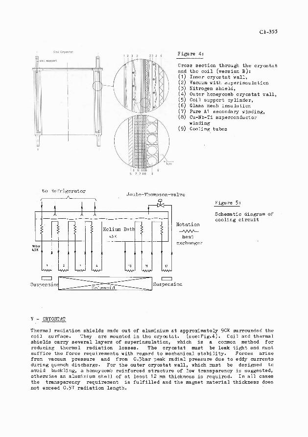
F i g u r e 4:
Cross s e c t i o n through t h e c r y o s t a t and t h e c o i l ( v e r s i o n B ) : ( 1 ) I n n e r c r y o s t a t w a l l , ( 2 ) Vacuum wi th s u p e r i n s u l a t i o n (3) Ni t rogen s h i e l d , (4 ) Outer honeycomb c r y o s t a t wa l l , ( 5 ) Co i l suppor t c y l i n d e r , ( 6 ) Glass mesh i n s u l a t i o n ( 7 ) Pure A1 secondary winding, (8) Cu-Nb-Ti superconductor
winding (9) Cooling t u b e s
F igu re 5:
Schematic diagram of c o o l i n g c i r c u i t
go ta t ion -vvv-
hes.t exchanger
0 0 Sus?ensio Suspension
V - CRYOSTAT
Thermal r a d i a t i o n s h i e l d s made o u t of aluminium a t approximate ly 90K surrounded t h e c o i l su r f ace . They a r e mounted i n t h e c r y o s t a t . ( s e e : ~ i ~ . 4 ) . C o i l and the rma l s h i e l d s c a r r y s e v e r a l l a y e r s of s u p e r i n s u l a t i o n , which is a common method f o r reducing the rma l r a d i a t i o n l o s s e s . The c r y o s t a t must be l e a k t i g h t and must s u f f i c e t h e f o r c e requirements w i th r ega rd t o mechanical s t a b i l i t y . Forces a r i s e from vacuum p r e s s u r e and from 0.5bar peak r a d i a l p r e s s u r e due t o eddy c u r r e n t s d u r i n g quench d i scha rge . Fo r t h e o u t e r c r y o s t a t w a l l , which must be des igned t o avoid buckl ing , a honeycomb r e i n f o r c e d s t r u c t u r e of low t r anspa rency is sugges ted , o the rwi se an aluminium s h e l l of a t l e a s t 12 mm t h i c k n e s s is r equ i r ed . I n a l l c a ses t h e t r anspa rency requirement i s f u l f i l l e d and t h e magnet m a t e r i a l t h i c k n e s s does not exceed 0.57 r a d i a t i o n l eng th .

JOURNAL DE PHYSIQUE
REFERENCES
/1/ Engfe r R . , Domingo J . , Wal ter H . C . , e t a l . , SINDRUM-Proposal, SIN. /2/ Zel lweger J . , I n t e r n a l Report KRYO-81.11 , SIN (1981). /3/ Genevey P . , l e Bars J . , 6 t h I n t e r n a t i o n a l Conference on Magnet Technology
(MT-61, B r a t i s l a v a , (1977). /4/ Green M.A. e t a l . , Adv. Cryog.Eng.3, (1980). /5/ Morpurgo M . , Cryogenics , February (1977) 89. /6/ Reeve P.A., I n t e r n a l Repor t , KRYO-81 . l o , SIN (1981). /7/ Vecsey G . , 5 t h I n t e r n a t i o n a l Conference on Magnet Technology (MT-5), Roma
f 1975).

![MuCool Superconducting Solenoid Quench …...Index Terms— Superconducting solenoid, Magnetic field, Quench, 3D simulations, Test Stand. I. INTRODUCTION HE MUCOOL experiment [1] magnet](https://img.pdfslide.us/doc/110x75/5e92b2bd1d72c02008514bd1/mucool-superconducting-solenoid-quench-index-termsa-superconducting-solenoid.jpg)


![Chapter 10 Superconducting Solenoid Magnets · Chapter 10 Superconducting Solenoid Magnets 10.1 Introduction TheNeutrinoFactory[1],[2],[3],beyondapproximately18mfromthetarget,requires](https://img.pdfslide.us/doc/110x75/5ec528158b55b07603639677/chapter-10-superconducting-solenoid-magnets-chapter-10-superconducting-solenoid.jpg)