Embed Size (px)
Citation preview
Department of Chemical Engineering
CHEE 457: Design Project II
Production of Stainless Steel
Presented to:Prof. Dimitrios BerkMrs. Nadia RomaniDr. Roger Urquhart
Submitted by:Mohammed Abu Shark - 260376614Spencer John Brennan - 260315605
Saikat Chanda - 260372492Michael Garibaldi - 260353823
Friday April 11th, 2014

Design II
Acknowledgements
As a group we would like to sincerely thank Mrs. Romani and Dr.
Urquhart for all their guidance and support throughout the year. Their
engineering experience and knowledge were instrumental in our
learning process. We are grateful to have learned from such
professional instructors.
ii
Design II
1. INTRODUCTION....................................................................................................................................................1
1.1 PROJECT MANDATE...............................................................................................................................................................1
1.2 PROJECT SCOPE......................................................................................................................................................................1
1.3 DELIVERABLES.......................................................................................................................................................................3
2. PROCESS DESIGN..................................................................................................................................................4
2.1 PROCESS DESCRIPTION.........................................................................................................................................................4
2.1.1 Midrex Direct Iron Reduction................................................................................................................................. 4
Midrex Shaft Furnace......................................................................................................................................................................4
Steam Reformer.................................................................................................................................................................................6
Venturi Scrubber...............................................................................................................................................................................8
Boiler...................................................................................................................................................................................................... 9
2.1.2 Electric Arc Furnace................................................................................................................................................... 9
EAF Function.......................................................................................................................................................................................9
Process Overview..............................................................................................................................................................................9
Block Flow Diagram...................................................................................................................................................................... 10
Process Description.......................................................................................................................................................................10
Summary of EAF Reactions........................................................................................................................................................12
2.1.4 Continuous Casting.................................................................................................................................................. 13
2.2 DESIGN CRITERIA............................................................................................................................................................... 14
2.3 MATERIAL AND ENERGY BALANCE.................................................................................................................................15
2.3.1Midrex Direct Iron Reduction............................................................................................................................... 15
Midrex Shaft Furnace....................................................................................................................................................................15
Steam Reformer.............................................................................................................................................................................. 18
Boiler................................................................................................................................................................................................... 22
Energy Balance for Remaining Equipment.........................................................................................................................23
2.3.2 Electric Arc Furnace................................................................................................................................................ 24
2.3.4 Continuous Casting.................................................................................................................................................. 27
Water-Cooled Mould Methodology........................................................................................................................................28
iii
Design II
Water Spray Chamber..................................................................................................................................................................32
Blower Section.................................................................................................................................................................................35
3. OPERATING PHILOSOPHY..............................................................................................................................37
3.1 CONTROL THEORY..............................................................................................................................................................37
3.2 PROCESS AND INSTRUMENTATION DIAGRAM DEVELOPMENT....................................................................................37
3.2.1 Overall P&ID Development................................................................................................................................... 37
3.2.2 Common Unit Control Philosophy...................................................................................................................... 37
Pumps and Compressors............................................................................................................................................................ 37
Control Valves..................................................................................................................................................................................38
3.2.3 Midrex Direct Iron Reduction.............................................................................................................................. 40
Midrex Shaft Furnace and Conveyor Belts..........................................................................................................................40
Steam Reformer.............................................................................................................................................................................. 41
Boiler................................................................................................................................................................................................... 43
Venturi Scrubber............................................................................................................................................................................ 44
Heat Exchanger............................................................................................................................................................................... 45
3.2.4 Control Philosophy Electric Arc Furnace........................................................................................................46
Cooling water flow rate............................................................................................................................................................... 46
Hydraulic mechanisms.................................................................................................................................................................49
Bin weighing control.....................................................................................................................................................................54
Fan speed control...........................................................................................................................................................................55
3.2.6 Continuous Casting Section.................................................................................................................................. 56
Flux Transport Control................................................................................................................................................................56
Molten Stainless Steel Flow Control.......................................................................................................................................57
Cooling Water Flow Control......................................................................................................................................................58
Mist Flow Control...........................................................................................................................................................................59
4. PLANT DESIGN....................................................................................................................................................60
4.1 EQUIPMENT SIZING............................................................................................................................................................60
4.1.1 Midrex Direct Iron Reduction.............................................................................................................................. 60
iv
Design II
Shaft Furnace................................................................................................................................................................................... 60
Air blower.......................................................................................................................................................................................... 60
Air compressors..............................................................................................................................................................................61
Venturi Scrubber............................................................................................................................................................................ 63
Boiler................................................................................................................................................................................................... 64
Conveyor belts................................................................................................................................................................................. 65
Heat Exchanger............................................................................................................................................................................... 66
4.1.2 Electric Arc Furnace................................................................................................................................................ 67
Transformers................................................................................................................................................................................... 69
Axial Vane Fans............................................................................................................................................................................... 70
Ladles.................................................................................................................................................................................................. 70
Bins....................................................................................................................................................................................................... 71
Lime Pebble Silos........................................................................................................................................................................... 72
Cranes.................................................................................................................................................................................................. 72
Conveyors.......................................................................................................................................................................................... 73
Suspended Magnet.........................................................................................................................................................................74
Cooling Bed and Excavator........................................................................................................................................................ 74
4.1.4 Continuous Casting Section.................................................................................................................................. 75
Tundish............................................................................................................................................................................................... 75
Flux Silo and Hopper (SI-03-401 and HP-03-401 and HP-03-402)..........................................................................76
Oscillating Water-Cooled Mould (MD-03-401 and MD-03-402)...............................................................................77
Spray Chamber (SC-03-401 and SC-03-402)......................................................................................................................79
Pneumatic Conveying...................................................................................................................................................................80
Rotary Screw Air Compressor (CP-03-401 A/B)..............................................................................................................82
Membrane Air dryer (DR-03-401)..........................................................................................................................................82
Bottom Discharge Blow Tanks (TA-03-401 to 404).......................................................................................................82
Axial-Flow Compressor and Centrifugal Pump for Spray Chamber Mix (CP-03-402 A/B to 403 A/B and
PP-03-403 A/B to 404 A/B)......................................................................................................................................................83
Water-Cooled Mould Pump........................................................................................................................................................84
Power-Driven Roller Conveyors (RL-03-401 to 458)....................................................................................................85
v
Design II
Roller Conveyor Slab Collection Rack (RA-03-401)........................................................................................................86
Blowers (BL-03-401 to 420).....................................................................................................................................................87
4.2 PLANT LAYOUT...................................................................................................................................................................88
5. ENVIRONMENTAL EVALUATION..................................................................................................................89
5.1 MIDREX PROCESS............................................................................................................................................................... 89
5.2 ELECTRIC ARC FURNACE...................................................................................................................................................89
5.4 CONTINUOUS CASTING.......................................................................................................................................................90
6. COST ANALYSIS.................................................................................................................................................91
6.1 CAPITAL EXPENDITURE (CAPEX)..................................................................................................................................91
Indirect Costs......................................................................................................................................................................... 95
6.2 OPERATING EXPENDITURES (OPEX).............................................................................................................................96
6.2.1 Net Present Value of Investment........................................................................................................................ 98
6.3 INTERNAL RATE OF RETURN............................................................................................................................................98
7. REFERENCES.....................................................................................................................................................100
APPENDIX A - MASS & ENERGY BALANCE.........................................................................................................I
A.2 ELECTRIC ARC FURNACE....................................................................................................................................................... I
A.4 CONTINUOUS CASTING......................................................................................................................................................VIII
APPENDIX B – EQUIPMENT SIZING..................................................................................................................XV
B.4 CONTINUOUS CASTING.......................................................................................................................................................XV
APPENDIX C – CAPEX & OPEX......................................................................................................................XXVII
C.1 CAPEX............................................................................................................................................................................... XXVII
C.2 - OPEX.............................................................................................................................................................................. XXXI
APPENDIX D – PROCESS FLOW DIAGRAMS...................................................................................................37
APPENDIX E – PROCESS & INSTRUMENTATION DIAGRAMS...................................................................44
vi
Design II
APPENDIX F – PLANT LAYOUT..........................................................................................................................51
APPENDIX F – EQUIPMENT LIST.......................................................................................................................56
List of Figures
Figure 1................................................................................................................................5
Figure 2................................................................................................................................7
Figure 3................................................................................................................................9
Figure 5..............................................................................................................................10
Figure 6..............................................................................................................................10
Figure 7..............................................................................................................................21
Figure 8..............................................................................................................................34
Figure 9..............................................................................................................................39
Figure 10............................................................................................................................40
Figure 11............................................................................................................................40
Figure 12............................................................................................................................42
Figure 13............................................................................................................................43
Figure 14............................................................................................................................44
Figure 15............................................................................................................................45
Figure 16............................................................................................................................46
Figure 17............................................................................................................................47
Figure 18............................................................................................................................48
Figure #9............................................................................................................................49
Figure 20............................................................................................................................49
vii
Design II
Figure #21..........................................................................................................................50
Figure 22............................................................................................................................51
Figure 23............................................................................................................................52
Figure 24............................................................................................................................53
Figure 25............................................................................................................................54
Figure 26............................................................................................................................55
Figure 27............................................................................................................................55
Figure 28............................................................................................................................56
Figure 29............................................................................................................................57
Figure 30............................................................................................................................58
Figure 31............................................................................................................................59
Figure 32............................................................................................................................60
Figure #33..........................................................................................................................63
Figure #34..........................................................................................................................64
Figure #35..........................................................................................................................65
List of Tables
Table 1...............................................................................................................................16
Table 2...............................................................................................................................20
Table 3...............................................................................................................................28
Table #4.............................................................................................................................65
Table 5...............................................................................................................................93
Table 6...............................................................................................................................96
Table 7...............................................................................................................................98
viii
Design II
Table 8..................................................................................................................................i
Table 9..................................................................................................................................i
Table 10...............................................................................................................................ii
Table 11..............................................................................................................................iii
Table 12............................................................................................................................viii
Table 13............................................................................................................................viii
Table 14..............................................................................................................................ix
Table 15.............................................................................................................................xii
Table 16............................................................................................................................xiii
Table 17............................................................................................................................xiii
Table 18............................................................................................................................xiv
Table 19.............................................................................................................................xv
Table #20..........................................................................................................................xvi
Table 21...........................................................................................................................xvii
Table 22..........................................................................................................................xviii
Table 23............................................................................................................................xix
Table #24...........................................................................................................................xx
Table #25..........................................................................................................................xxi
Table #26..........................................................................................................................xxi
Table #27.........................................................................................................................xxii
Table #28........................................................................................................................xxiii
Table #29........................................................................................................................xxiii
Table #29........................................................................................................................xxiv
ix
Design II
Table #30........................................................................................................................xxiv
Table #31.........................................................................................................................xxv
Table #32.........................................................................................................................xxv
Table #33........................................................................................................................xxvi
Table 34.........................................................................................................................xxvii
Table #35......................................................................................................................xxviii
Table #36......................................................................................................................xxviii
Table #37........................................................................................................................xxix
Table 39.............................................................................................................................34
Table 40.............................................................................................................................36
x
Design II
1. Introduction
1.1 Project Mandate
Inox has selected three McGill consulting teams to design a complex in Quebec
for the production of stainless steel slabs by exploiting the chromite deposit from the
“Ring of Fire”. The project mandate of Group 3 is to produce 2 million tonnes of
stainless steel per annum. In order to satisfy the mandated tonnage, 1,400,550 tonnes per
annum of iron ore pellets, 150,000 tonnes per annum of steel scrap and 400,000 tonnes
per annum of ferronickel are procured, while, 600,000 tonnes of high carbon
ferrochromium (HCFeCr) is received from Groups 1 and 2.
1.2 Project Scope
Group 3 will design processes to produce the solidified stainless steel slabs with
dimensions 10 m x 0.25 m x 1 m at a composition of 18 % chromium, 0.08 % carbon and
8 % nickel. To produce such slabs, there are four main process steps required:
(1) Iron ore reduction in the Midrex Direct Iron Reduction Process
(2) Heating and further reduction of carbon in the Electric Arc Furnace (EAF)
(3) Oxidation and addition of chromium in the Argon Oxygen Decarburizer (AOD)
(4) Cooling of molten stainless steel for slab production by continuous casting
The aforementioned processes will be designed in full, from mass and energy
balance considerations and engineering drawings such as block flow diagrams (BFD),
process flow diagrams (PFD) and process and instrument diagrams (P&ID). Equipment
will be sized based on process flow calculations and the most suitable will be chosen and
recommended for implementation. A layout of the stainless steel production plant will be
provided – both top view and side view – indicating the preferred location of the process
equipment. A complete capital and operating economic evaluation (CAPEX and OPEX)
will be performed and the return on investment (ROI) based on the produced tonnage per
annum will be determined. To ensure the plant has the ability to meet future imposed
xi
Design II
environmental regulations, sustainable design aspects will be considered and a full
environmental evaluation completed.
Battery limits of the project define a process perimeter, limiting the scope of
group 3’s design responsibilities. Engineering design, sizing and costing of the processes
used to produce stainless steel are all within the battery limits of the outlined Inox
project. The specific aspects not within the battery limits of this project are:
The source and transportation of high carbon ferrochromium received in either
granulated or molten form Groups 1 and 2
The source and all aspects of pumping (including costing) of cooling water, which is
received from Group 2
All aspects of the process water treatment and return to the environment (although
pumping to the wastewater treatment plant is accounted for)
The distribution of slabs to their final market destination
The cost of all other raw materials (iron ore pellets, ferronickel (FeNi40) and steep scrap)
and utilities are accounted for during operation and procurement. Transportation costs
upon procurement are included in the price per unit quantity purchased.
xii
Design II
1.3 Deliverables
The following deliverables were included on the final report:
Executive Summary Overall Block Flow Diagram (BFD) Overall Process Flow Diagram (PFD) Process description Equipment description Overall Control strategy Engineering Drawings :
Individual Block Flow Diagram (BFD) Individual Process Flow Diagram (PFD) Individual Piping & Instrumentation Diagram (P&ID)
Plot Plan Economic evaluation (CAPEX, OPEX, ROI) Environmental Evaluation Mass and Energy balances Equipment Sizing Breakdown of Responsibilities
2. Process Design
xiii
Design II
2.1 Process Description
2.1.1 Midrex Direct Iron Reduction
Midrex Shaft Furnace
The Midrex direct reduction system is a gas-based reduction process from which
the production of sponge iron can be achieved. The main difference between the sponge
iron, commonly referred to as direct reduced iron (DRI), and iron ore pellets feed is their
oxygen content. The iron ore contains approximately 30wt% oxygen while the direct
reduced iron has 3wt%. In order to reduce the oxygen content, the iron oxide (fe2O3;
96.8wt%) present in iron ore will undergo a series of consecutive oxidation-reduction
reactions, shown below, with a gas stream high in CO and H2 content, to form metallic
iron, carbon dioxide and steam:
(1) 3Fe2O3 + CO → 2Fe3O4 + CO2
(2) 3Fe2O3 + H2 → 2Fe3O4 + H2O (3) Fe3O4 + CO → 3FeO + CO2
(4) Fe3O4 + H2 → 3FeO + H2O (5) FeO + CO → Fe + CO2
(6) FeO + H2 → Fe + H2O
To a small extent, the metallic iron product is further reduced by carbon
monoxide and hydrogen by the following carburization reactions:
(7) 3Fe + 2CO → Fe3C + CO2
(8) 3Fe + CO + H2 → Fe3C + H2O
Traditionally, this process has been completed using blast furnaces, however since
they require high quality coke, auxiliary plants for raw material handling, higher
operating temperature and three times the CO2 emissions of direct iron reduction
methods, they are not favoured for iron ore reduction processes (Chatterjee, 1994). The
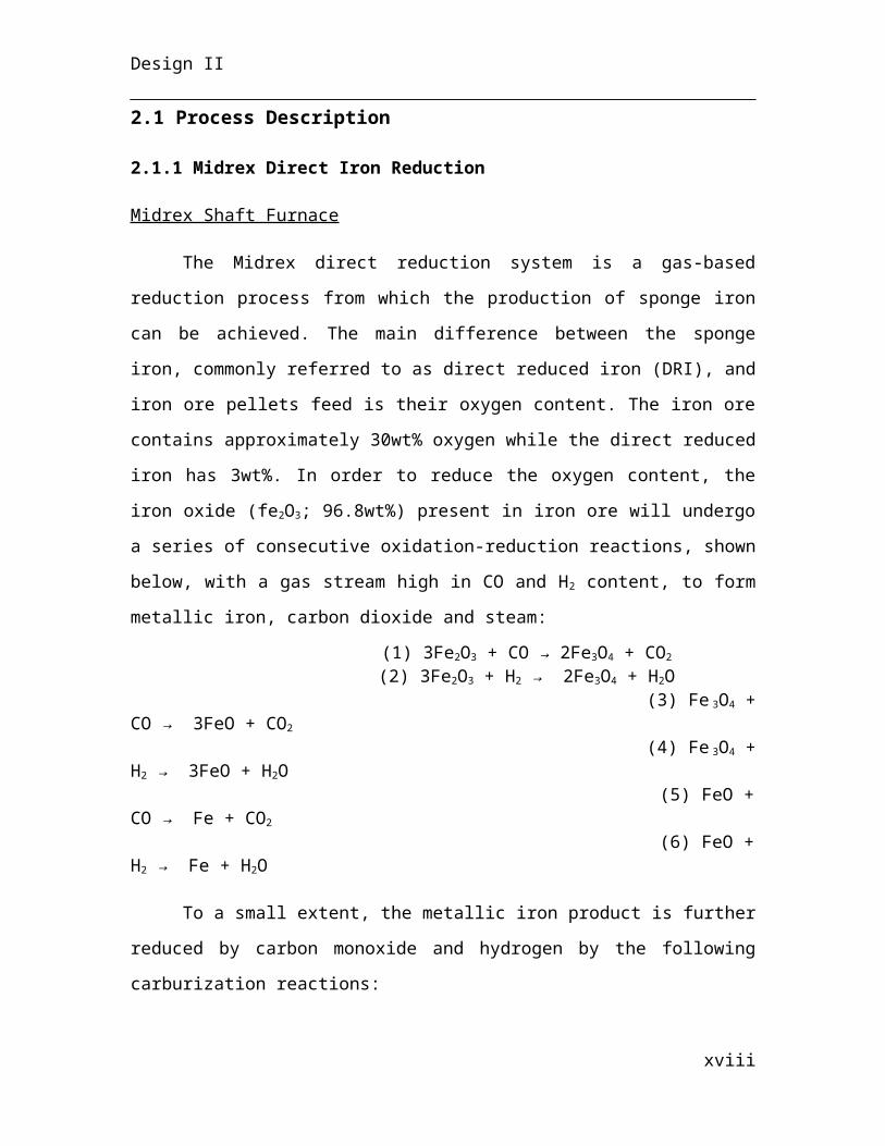
oxidation-reduction reactions are carried out in a shaft furnace where the iron ore pellets
are fed from the top through a charge hopper while the syngas stream flowing from the
bottom through tuyere. Feeding the reactants to the Midrex furnace in this counter-
current fashion allows for efficient heat transfer to occur between the solids and gases
(Anameric et al., 2007).
xiv
Design II
Figure 1The Midrex unit is operated in a counter-current fashion to increase heat transfer between the gases and
solids (Anameric et al., 2007).
The incoming syngas enters the furnace at 894oC, heating the iron ores and leaves
as off-gas at 450 oC. The overall reduction process is endothermic (105 kJ/mol; 25 oC),
thus requiring an additional source of heating.
The sponge iron can be discharged in three different manners from the Midrex
furnace: cold DRI, hot DRI and hot briquetted DRI. Cold and briquetted DRI are
effective for storage and shipping, however since the reduced iron will be further
processed in the electric arc furnace (EAF), hot DRI is preferred since it is discharged at
a temperature of 650 oC, thus cutting down on the EAF’s energy consumption.
The chemical composition of the DRI is dependent on the quality of the iron ore
feed. A higher iron oxide percent in the pellets will give higher iron content in the
product and lower gangue amount (Anameric et al., 2007). Referring to the list of design
criteria in section X, the DRI composition has four criteria that need to be met: 3wt
%FeO, 1.6wt%C, 90% of FeS retained in the DRI and 100% of the remaining gangue
material retained in the DRI. The iron metallization percent is used to determine the
extent of iron reduction. For the given iron ore pellet composition and the DRI criteria
xv
Design II
needed, the sponge iron has a degree of metallization of 93.3%. This is within the
common metallization range of 90-94% for Midrex processes (Midrex Technologies,
2013).
Steam Reformer
The steam reformer is a catalytic process that converts natural gas and steam into
hydrogen and carbon monoxide gas. The reformer has two sets of reactions taking place:
the reforming reactions, which produced the syngas mixture (CO and H2) and the
combustion reactions which provides the heat input required for the endothermic
reforming reactions. The reforming reactions taking place depends on the composition of
the natural gas feed. For this case, methane, ethane, propane, butane and pentane react to
form syngas as follows:
(9) CH4 + H2O → CO + 3H2
(10) C2H6 + 2H2O → 2CO + 5H2
(11) C3H8 + 3H2O → 3CO + 7H2
(12) C4H10 + 4H2O → 4CO + 9H2
(13) C5H12 + 5H2O → 5CO + 11H2
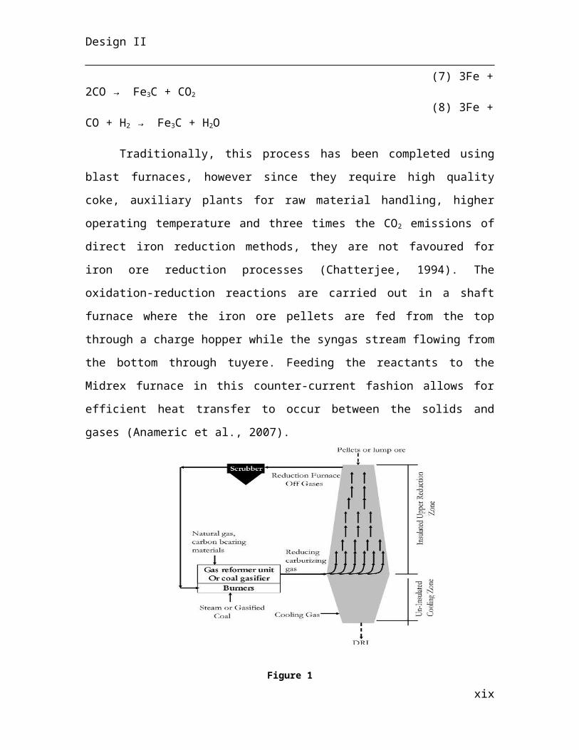
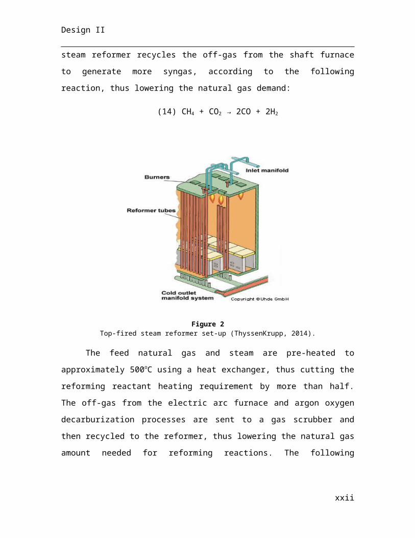
The reforming reactions take place inside nickel catalyst-filled tubes that are vertically
mounted inside the combustion chamber. The burners and tubes can be arranged
according to either a top-fired or side-fired design. A top-fired design was used in this
process because of higher heat transfer efficiency compared to side-fired designs, using
twice as less burners (GBH Enterprises, 2013). The Midrex steam reformer recycles the
off-gas from the shaft furnace to generate more syngas, according to the following
reaction, thus lowering the natural gas demand:
(14) CH4 + CO2 → 2CO + 2H2
xvi
Design II
Figure 2Top-fired steam reformer set-up (ThyssenKrupp, 2014).
The feed natural gas and steam are pre-heated to approximately 500oC using a
heat exchanger, thus cutting the reforming reactant heating requirement by more than
half. The off-gas from the electric arc furnace and argon oxygen decarburization
processes are sent to a gas scrubber and then recycled to the reformer, thus lowering the
natural gas amount needed for reforming reactions. The following combustion reactions
take place inside the combustion chamber:
(15) CH4 + 2O2 → CO2 + 2H2O (16) C2H6 + 7/2O2 → 2CO2 + 3H2O
(17) C3H8 + 5O2 → 3CO2 + 4H2O (18) C4H10 + 13/2O2 → 4CO2 + 5H2O
(19) C5H12 + 8O2 → 5CO2 + 6H2O
Air is used as the source of oxygen and is blown into the system using an air
blower. It is assumed that the syngas leaves the reformer furnace at approximately 900oC
and is heated entirely by the combustion of natural gas by reaction 15-19. The
combustion flue gas leaves the system through tunnels located at the bottom and is used
to pre-heat incoming reactants in the heat exchanger.
xvii
Design II
Venturi Scrubber
A venturi scrubber is used to remove dust particles contained in the off-gasses of
the EAF and AOD process before recycling them into the Midrex reformer. Venturi’s are
classified as a wet scrubber method since water is used to remove the particles of interest.
The incoming gas stream’s speed is accelerated due to inertia when moving down the
throat section of the scrubber. This will cause, upon contact with water, the formation of
many small water droplets at the throat section of the scrubber. When the dust particles
enter the throat section of the venturi scrubber, they collide with the tiny water droplets
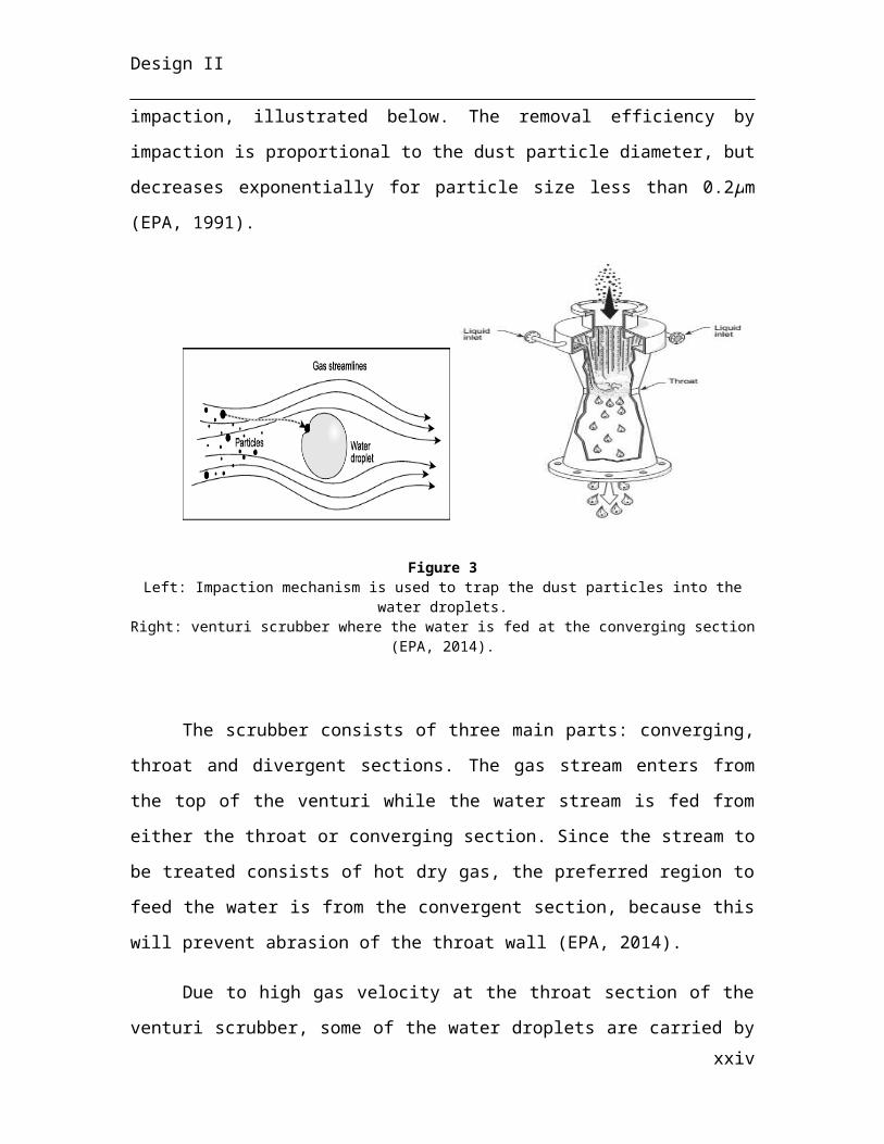
by impaction, illustrated below. The removal efficiency by impaction is proportional to
the dust particle diameter, but decreases exponentially for particle size less than 0.2μm
(EPA, 1991).
Figure 3Left: Impaction mechanism is used to trap the dust particles into the water droplets.
Right: venturi scrubber where the water is fed at the converging section (EPA, 2014).
The scrubber consists of three main parts: converging, throat and divergent
sections. The gas stream enters from the top of the venturi while the water stream is fed
from either the throat or converging section. Since the stream to be treated consists of hot
dry gas, the preferred region to feed the water is from the convergent section, because
this will prevent abrasion of the throat wall (EPA, 2014).
xviii
Design II
Due to high gas velocity at the throat section of the venturi scrubber, some of the
water droplets are carried by the gas stream, creating entrainment droplets, thus venturi
scrubbers are commonly followed by a cyclone for mist elimination.
Boiler
The reforming reactions require steam in order to produce the syngas stream. This
will be provided by boiling process water and heating to 400oC by using a water boiler to
form super-heated steam. The boiler consists of a three-pass steam fire-tube. The boiler
transfers heat similar to a shell-and-tube heat exchanger, where the hot gases from
combustion flow through the tubes, while the water is contained in the shell. A large
capacity boiler was chosen (1300-2300 BHP) to meet the required power of 1800 boiler
horsepower (BHP). The heating will be provided by the combustion of natural gas instead
of oil, since natural gas is already used in other equipment of the Midrex process.
2.1.2 Electric Arc Furnace
EAF Function
An electric arc furnace (EAF) has three primary functions:
1. To contain the steel scrap and direct reduced iron;2. To heat and melt the steel scrap and direct reduced iron;3. To transfer the molten steel to the next processing stage.
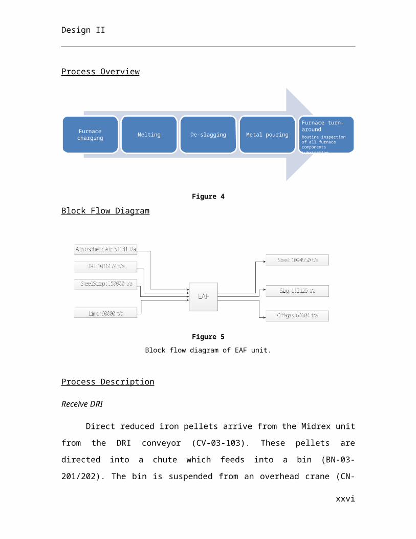
Process Overview
Figure 4
Furnace charging Melting De-slagging Metal pouring
Furnace turn-aroundRoutine inspection of all furnace componentsLubrication
xix
Design II
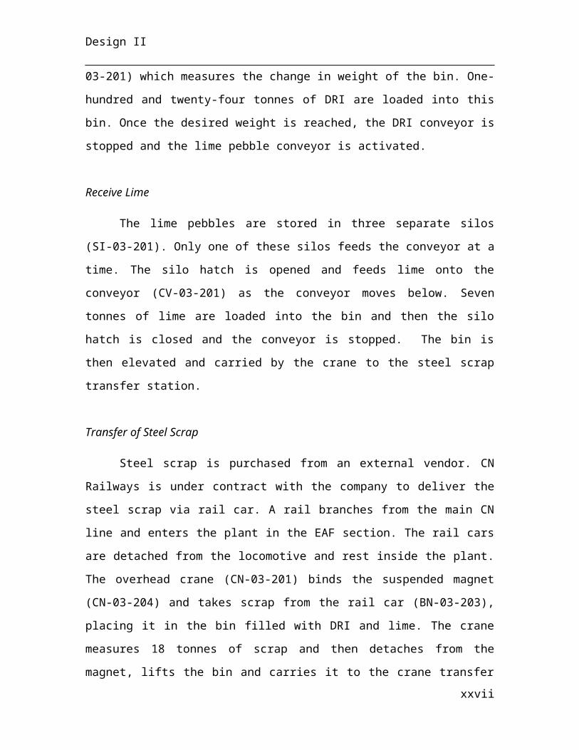
Block Flow Diagram
Figure 5
Block flow diagram of EAF unit.
Process Description
Receive DRI
Direct reduced iron pellets arrive from the Midrex unit from the DRI conveyor
(CV-03-103). These pellets are directed into a chute which feeds into a bin (BN-03-
201/202). The bin is suspended from an overhead crane (CN-03-201) which measures the
change in weight of the bin. One-hundred and twenty-four tonnes of DRI are loaded into
this bin. Once the desired weight is reached, the DRI conveyor is stopped and the lime
pebble conveyor is activated.
Receive Lime
The lime pebbles are stored in three separate silos (SI-03-201). Only one of these
silos feeds the conveyor at a time. The silo hatch is opened and feeds lime onto the
conveyor (CV-03-201) as the conveyor moves below. Seven tonnes of lime are loaded
into the bin and then the silo hatch is closed and the conveyor is stopped. The bin is then
elevated and carried by the crane to the steel scrap transfer station.
Transfer of Steel Scrap
Steel scrap is purchased from an external vendor. CN Railways is under contract
with the company to deliver the steel scrap via rail car. A rail branches from the main CN
xx
Design II
line and enters the plant in the EAF section. The rail cars are detached from the
locomotive and rest inside the plant. The overhead crane (CN-03-201) binds the
suspended magnet (CN-03-204) and takes scrap from the rail car (BN-03-203), placing it
in the bin filled with DRI and lime. The crane measures 18 tonnes of scrap and then
detaches from the magnet, lifts the bin and carries it to the crane transfer station. Here the
bin is placed below another overhead crane (CN-03-202/203).
Charging EAF
The second crane in the process lifts the bin and positions it above the electric arc
furnace. With the roof of the EAF (RF-03-201/202) raised and to the side, the crane
charges the furnace by emptying the materials of the bin into the hearth (EAF-03-
201/202).
Moving of Roof, Turning on Fan, Switching on Current, Lowering Electrodes
The roof (RF-03-201) then moves into position above the furnace shell. Once the
roof is in place, the axial vane fan (FA-03-201) is turned on to begin venting. The control
valve for the cooling water (FCV-03-205) is opened to begin the flow of water to the
roof, bus bar (BB-03-201) and electrodes (EE-03-201). Pressure of the furnace is
measured to regulate the fan speed. The switch is then turned on to initiate the current
transfer from the transformer station, through the power cables and the bus bar and into
the three graphite electrodes. The height of the bus bar is then lowered, bringing the hot
electrodes into contact with the contents of the hearth.
Melting Charge
The initial melt takes fifteen minutes to achieve. To avoid fracturing the
electrodes, the height of the electrodes is initially above the mass of DRI, scrap and lime.
After fifteen minutes, the top layer of scrap and DRI is melted and the electrodes are
lowered further to bore into the material and expedite melting. The height of the
electrodes gradually decreases over the remaining forty-five minutes. After an hour, the
xxi
Design II
current is switched off and the bus bar is raised to remove the electrodes from the bath of
slag and hot metal. During the melting period, temperatures inside the bath reach 1600°C.
Slag Removal
The slag forms a fluid layer on top of the molten metal. The slag door is located
above the top of the slag. It is opened using the hydraulic mechanism, creating a path for
slag to flow down the slag launder (LA-03-202) and into the slag pot (LC-03-201). The
furnace is tilted using the hydraulic mechanism and the slag pours out of the furnace. The
slag door is closed and the furnace is tilted upright once the slag ceases to flow.
The slag pot is positioned on a slag pot car, which moves automatically along a
rail to the outdoor cooling bed (CB-03-201). Upon reaching the cooling bed, the slag pot
is tipped on its side to pour out the molten slag. It is left to cool and solidify into grains.
An excavator (EX-03-201) removes the slag from the concrete bed and piles it on the slag
deposit (DP-03-201). It remains in the deposit until a disposal contractor moves it to
another remote location.
Hot Metal Tapping
The hot metal door is located above the hot metal launder (LA-03-201). It is
opened with the hydraulic mechanism and the furnace is tilted to allow the hot metal to
flow along the launder and into the hot metal ladle (LD-03-201).
Transfer of Hot Metal Ladle
The hot metal ladle is located beneath the overhead crane (CN-03-202). The crane
lifts the ladle and carries it to the Argon Oxygen Decarburization unit, where it undergoes
further processing.
Summary of EAF Reactions
Reaction1 : F e3C →3 Fe+CReaction2 : FeS+CaO→ FeO+CaS
Reaction3 : FeO+C →Fe+COxxii
Design II
2.1.4 Continuous Casting
Continuous strand casting is the process by which molten metal is solidified to a
strand of solid. Through the storage of molten stainless steel in the tundishes the stainless
steel production process is converted from batch to continuous. The restricting element
of the casting process is the heat removal rate. At the specified design capacity of 2
million t/a stainless steel production, there are two full gravity arc casting systems
employed. Cooling of the stainless steel from 1800 °C to room temperature occurs in
three main stages in continuous casting:
1. Primary cooling via the water-cooled copper mould
2. Secondary cooling via the spray chamber
3. tertiary cooling via numerous air blowers
Molten stainless steel tapped from the AOD in batches, is delivered to the
tundishes in crane-transported ladles. The stopper-controlled rod and nozzle allows for
the casting rate to be kept constant while the tundishes’ volumes vary. A CaF2 flux is
added to the tundish to minimise oxidation of the stainless steel, as well as provide vital
lubrication between the solidified stainless steel wall and oscillating water-cooled mould.
Molten steel is partially solidified in primary cooling, whereby the cooling water
runs counter-current to the stainless steel being cast. The mould removes approximately
20 % of the total required sensible and latent heat load, however, it provides integral
outer wall strength to the strand (solidifying 18 % of the steel) prior to reaching the spray
chamber.
Secondary cooling in the spray chamber, removes heat via evaporation of a water
mist created by mixing compressed air and water at an equal volumetric ratio. The spray
chamber introduces the water mist via nozzle spray directly onto the cast (and rollers),
xxiii
Design II
while the rollers provide directional guidance to the strand, ensure it is properly
supported as well as imposing its shape via compression. The spray chamber guides the
strand down the 12.2 m radius arc from upper plant floor to the ground floor. It also
extends for four meters beyond the arc in a straight section. This cooling process
solidifies the remainder of the strand and reduces the temperature at the outlet to 400 °C.
The strand is transported by individually power-driven stainless steel rollers upon
exit from the spray chamber. The strand is cut into individual slabs 10 m in length by an
oxyacetylene torch and eventually rolled to the slab collection rack. The slabs remain on
the collection rack for 4.21 hours, where tertiary heat removal occurs via forced air
convection with industrial scale blowers to 90 °C. From here slabs are lifted by a large
hoisting crane to inventory and subsequently to a flatbed truck or to a railcar for transport
to industry.
2.2 Design Criteria
xxiv
Design II
xxv
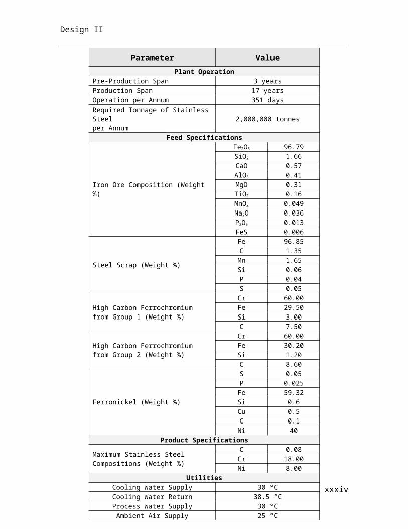
Parameter Value
Plant OperationPre-Production Span 3 yearsProduction Span 17 yearsOperation per Annum 351 daysRequired Tonnage of Stainless Steelper Annum 2,000,000 tonnes
Feed Specifications
Iron Ore Composition (Weight %)
Fe2O3 96.79SiO2 1.66CaO 0.57AlO3 0.41MgO 0.31TiO2 0.16MnO2 0.049Na2O 0.036P2O5 0.013FeS 0.006
Steel Scrap (Weight %)
Fe 96.85C 1.35
Mn 1.65Si 0.06P 0.04S 0.05
High Carbon Ferrochromium from Group 1 (Weight %)
Cr 60.00Fe 29.50Si 3.00C 7.50
High Carbon Ferrochromium from Group 2 (Weight %)
Cr 60.00Fe 30.20Si 1.20C 8.60
Ferronickel (Weight %)
S 0.05P 0.025Fe 59.32Si 0.6Cu 0.5C 0.1Ni 40
Product Specifications
Maximum Stainless Steel Compositions (Weight %)
C 0.08Cr 18.00Ni 8.00
UtilitiesCooling Water Supply 30 °CCooling Water Return 38.5 °CProcess Water Supply 30 °CAmbient Air Supply 25 °C
Design II
2.3 Material and Energy Balance
2.3.1Midrex Direct Iron Reduction
Midrex Shaft Furnace
Mass balance
The mass balance on the shaft furnace was started by first specifying the amount
of reactants and products needed for each reaction taking place in the system. The
reactions in the shaft furnace happen consecutively in group of two reactions, meaning a
group of two reactions can be written as one reaction for the purpose of calculating the
stoichiometric amount of reactants and products. Thus, the first two reactions take place
simultaneously and are followed by reaction 3-4 and so forth. The amount of reactants
and products are calculated based on stoichiometric amount of mol of the limiting
reactant in each group of reaction, while taking into consideration the conversion % for
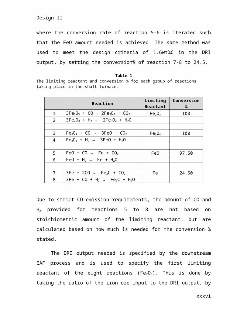
each reaction. Table #1 below shows the limiting reactant and conversion % for each
group of reaction taking place together. Based on the design criteria provided by Inox
Inc, the 3wt% FeO in the DRI output is achieved by setting the conversion % to 97.5 in
reaction 5-6. This number was found using the excel solver function, where the
conversion rate of reaction 5-6 is iterated such that the FeO amount needed is achieved.
The same method was used to meet the design criteria of 1.6wt%C in the DRI output, by
setting the conversion% of reaction 7-8 to 24.5.
Table 1The limiting reactant and conversion % for each group of reactions taking place in the shaft furnace.
Reaction Limiting Reactant Conversion %
1 3Fe2O3 + CO → 2Fe3O4 + CO2 Fe2O3 1002 3Fe2O3 + H2 → 2Fe3O4 + H2O
3 Fe3O4 + CO → 3FeO + CO2 Fe3O4 1004 Fe3O4 + H2 → 3FeO + H2O
xxvi
Design II
5 FeO + CO → Fe + CO2 FeO 97.506 FeO + H2 → Fe + H2O
7 3Fe + 2CO → Fe3C + CO2 Fe 24.508 3Fe + CO + H2 → Fe3C + H2O
Due to strict CO emission requirements, the amount of CO and H2 provided for reactions
5 to 8 are not based on stoichiometric amount of the limiting reactant, but are calculated
based on how much is needed for the conversion % stated.
The DRI output needed is specified by the downstream EAF process and is used
to specify the first limiting reactant of the eight reactions (Fe2O3). This is done by taking
the ratio of the iron ore input to the DRI output, by taking a basis of calculation of Fe2O3
mass. Once the amount of first limiting reactant is computed, all stream flowrate except
the syngas can be known.
Once the amount of reactant and products are calculated by taking a basis of
calculation, the next step is to determine the stream composition and mass flowrate of
each stream of the system. The iron ore pellet composition is given by Inox Inc, which
contains the Fe2O3 reactant. It is assumed that it is the only species that react from the
iron ores. Thus, knowing the Fe2O3 needed allows us to specify the mass flowrate of the
iron ore stream. Similarly, the DRI flowrate is determined by adding the ferrous products
and reactant left from each of the eight reactions and adding them to the unreacted
species contained in the iron ore. The other two reactants (CO and H2) are coming from
the syngas produced from the steam reformer.
The syngas mass flowrate and composition is determined from the reformer’s
mass balance. The off-gas stream of the Midrex shaft furnace consists of the CO2 and
H2O generated from all eight reactions and any gas and solid that does not react from the
syngas stream.
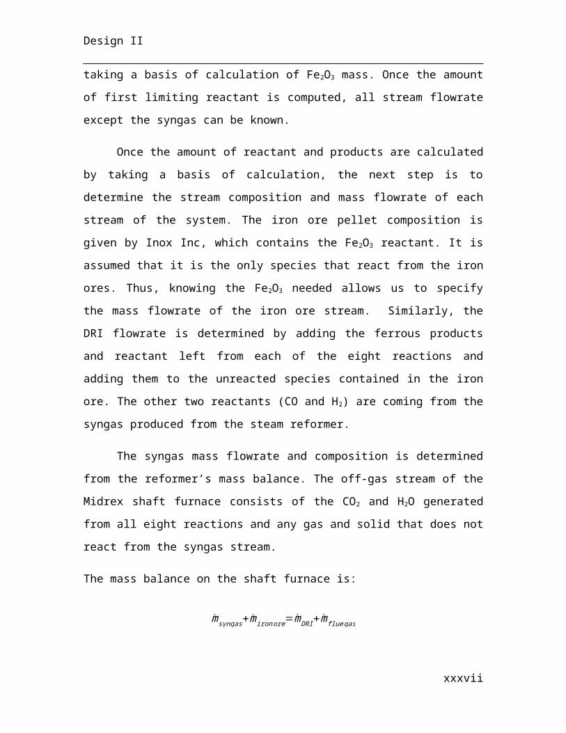
The mass balance on the shaft furnace is:
msyngas+miron ore=mDRI+mflue gas
xxvii
Design II
Where m represents the mass flowrate of a stream.
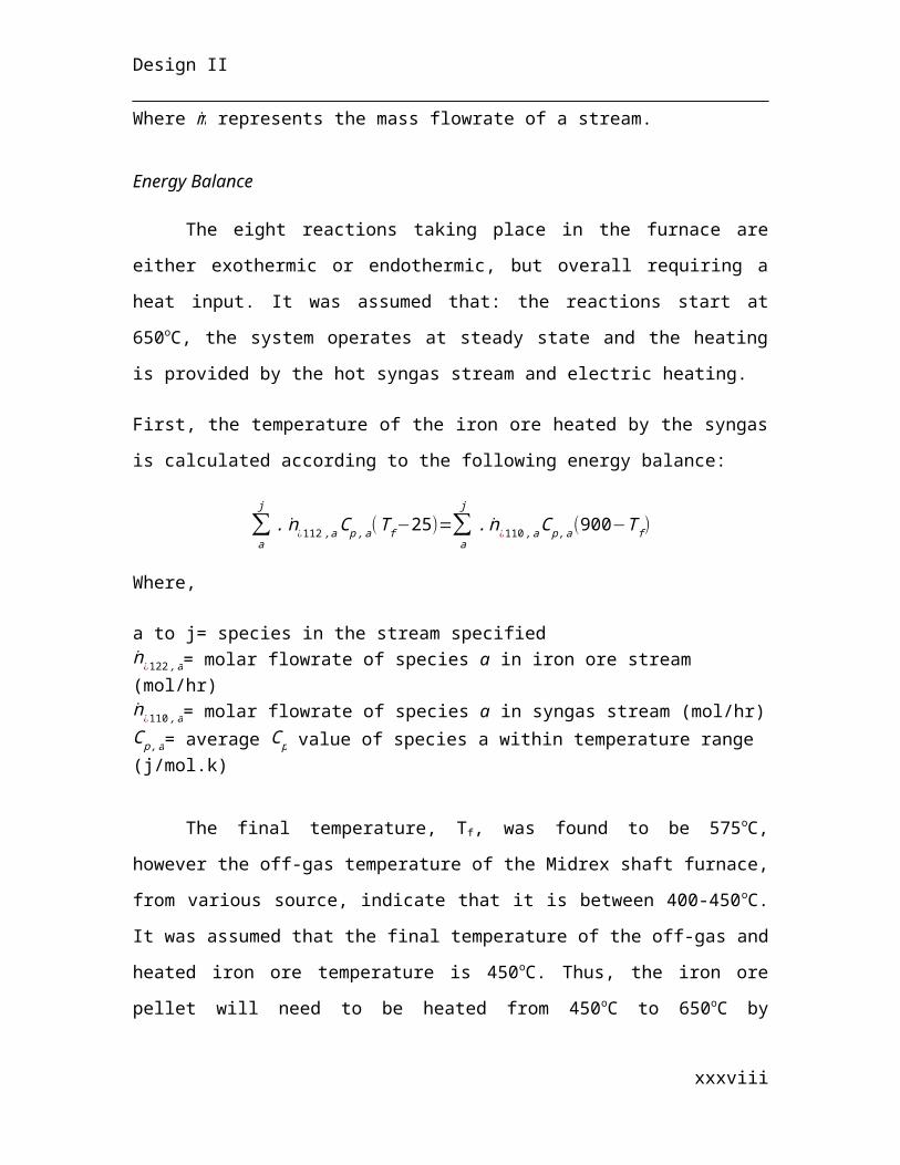
Energy Balance
The eight reactions taking place in the furnace are either exothermic or
endothermic, but overall requiring a heat input. It was assumed that: the reactions start at
650oC, the system operates at steady state and the heating is provided by the hot syngas
stream and electric heating.
First, the temperature of the iron ore heated by the syngas is calculated according to the
following energy balance:
∑a
j
.n¿112 ,a C p ,a(T f −25)=∑a
j
. n¿ 110 ,a Cp ,a(900−T f )
Where,
a to j= species in the stream specifiedn¿ 122, a= molar flowrate of species a in iron ore stream (mol/hr)n¿ 110 ,a= molar flowrate of species a in syngas stream (mol/hr)C p ,a= average C p value of species a within temperature range (j/mol.k)
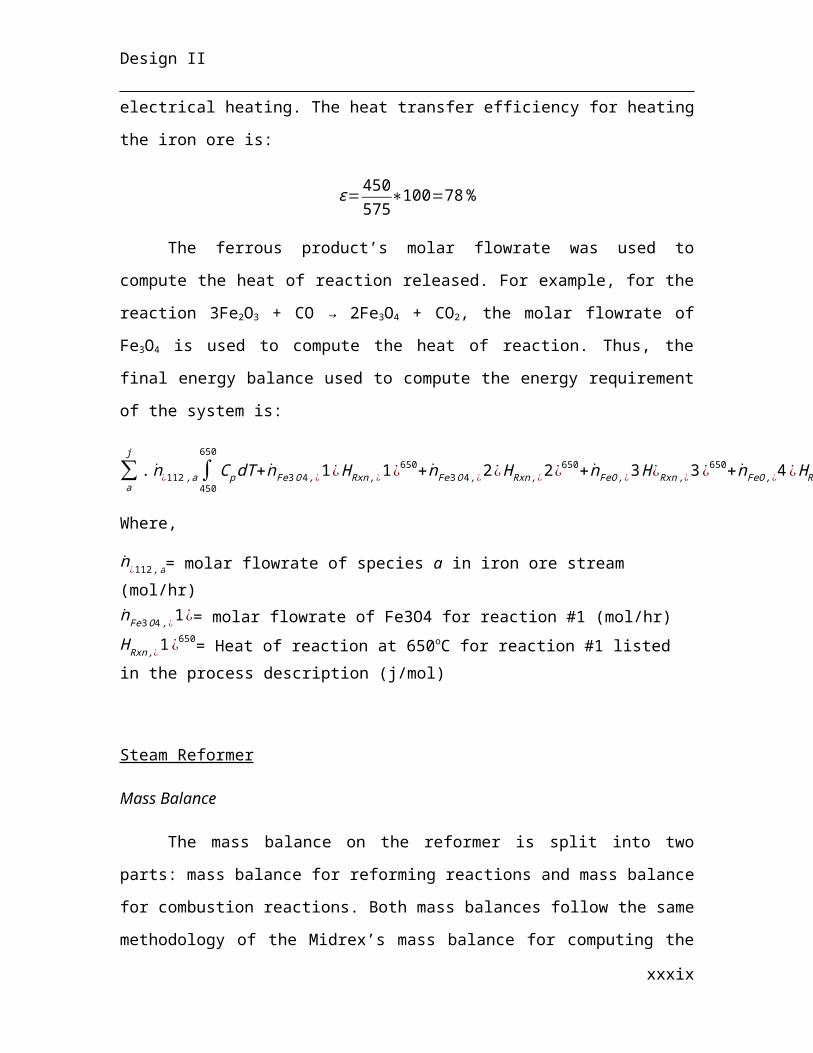
The final temperature, Tf, was found to be 575oC, however the off-gas
temperature of the Midrex shaft furnace, from various source, indicate that it is between
400-450oC. It was assumed that the final temperature of the off-gas and heated iron ore
temperature is 450oC. Thus, the iron ore pellet will need to be heated from 450oC to
650oC by electrical heating. The heat transfer efficiency for heating the iron ore is:
ε=450575
∗100=78 %
The ferrous product’s molar flowrate was used to compute the heat of reaction
released. For example, for the reaction 3Fe2O3 + CO → 2Fe3O4 + CO2, the molar flowrate
of Fe3O4 is used to compute the heat of reaction. Thus, the final energy balance used to
compute the energy requirement of the system is:
∑a
j
.n¿112 ,a ∫450
650
Cp dT +nFe3 O4 ,¿ 1¿H Rxn,¿1¿650+nFe3 O4 , ¿2¿ H Rxn ,¿2¿650+ nFeO ,¿ 3 H ¿Rxn ,¿3¿650+ nFeO ,¿ 4¿ HRxn, ¿4¿650+nFe, ¿5¿H Rxn ,¿5¿650+nFe, ¿6 ¿H Rxn ,¿ 6¿650+ nFe3C , ¿7¿ HRxn, ¿7 ¿650+nFe3 C , ¿8 ¿ HRxn ,¿ 8¿650=Qf
xxviii
Design II
Where,
n¿ 112 ,a= molar flowrate of species a in iron ore stream (mol/hr)nFe3 O4 ,¿1¿= molar flowrate of Fe3O4 for reaction #1 (mol/hr)H Rxn,¿1¿650= Heat of reaction at 650oC for reaction #1 listed in the process description (j/mol)
Steam Reformer
Mass Balance
The mass balance on the reformer is split into two parts: mass balance for
reforming reactions and mass balance for combustion reactions. Both mass balances
follow the same methodology of the Midrex’s mass balance for computing the reactants
and products mass based on stoichiometric amount, by taking a basis of reactant for each
reaction. However, unlike the shaft furnace’s mass balance, the reactions take place at the
same time instead of consecutively. For both the reforming and combustion reactions, all
reactions conversion is assumed to be 100% and the hydrocarbon reactants are provided
by a natural gas stream with a range for each species composition.
For the reforming reactions, both products (CO and H2) are the same for all
reactions. CO was taken as the basis of calculation for all reactants and products, since its
amount is calculated from the Midrex shaft furnace’s mass balance, but also because the
reforming reactions produce an excess amount of H2 than is needed for the shaft furnace.
In order to split how much CO is produced from each reforming reaction, the
composition of natural gas is used, since all the hydrocarbon reactants are provided only
from the natural gas feed. The natural gas composition was compared between Enbridge
and Union gas from their respective websites. Enbridge provides fixed natural gas
composition while union gas provides a range of composition. The Enbridge
compositions were first taken to provide a basis of calculation for the reforming
reactions.
The CO amount produced from the reforming reactions was first split based on
the Enbridge composition, however the presence of unreactive species in the stream
xxix
Design II
requires the percentage of CO generated from each reactions to be changed. For example,
the reactive species from the natural gas stream makes up 97.8mol% of the total stream,
therefore, when splitting how much CO is produced from each reaction, the remaining
2.2mol% were divided between each reaction. This method however would always
produce less CO than is needed by nearly 1-2%. To meet the CO flue gas emission
requirements, excess amount of CO was not added. This was fixed using the excel solver
function where the amount of CO produced from each reaction is iterated to meet the
required demand of the shaft furnace. This process alters the composition of the reactive
species from the natural gas stream but is within the range given from Union gas’s
website, as shown in table #2 below.
Table 2
Natural gas composition from Enbridge and Union gas supplier, compared to the iterated values from the reformer process.
The amount of steam required for the reforming reactions was not based on
stoichiometric amount of CO needed, but is instead based on steam to carbon ratio (S/C),
xxx
Species Enbridge (mol%) Union gas (mol%) Final (mol%)methane 95 87-97 95.40ethane 2.50 1.5-7 1.47propane 0.20 0.1-1.5 0.43butane 0.06 0.01-0.3 0.25pentane plus 0.02 trace-0.4 0.19nitrogen 1.60 0.2-5.5 1.60carbon dioxide 0.62 0.1-1 0.62
Design II
in order to reduce the risk of carbon deposition on the catalyst surface (Subramani et al,
2009), as illustrated in figure #7 below:
Figure 6Steam to carbon ratio with respect to operating temperature, pressure and conversion % (Subramani et al,
2009).
The operating temperature of 900oC was picked from the literature on the Midrex
process, thus in order to achieve a 100% conversion as is assumed for the reforming
reactions, a minimum S/C ratio of 1.4 would be needed.
The recycle stream from the Midrex shaft furnace is specified based on how much
CO2 reactant is needed from the reforming reactions. Thus, 39% of the shaft furnace’s
off-gasses are recycled back to the reformer, which includes any unreacted species
coming from the syngas stream of the reformer.
The following mass balance shows the final incoming and outgoing streams of the
system, for the reforming reactions:
mnatual gas+msteam+39 %∗mMidrex off gas=msyngas
For the combustions reaction of it was assumed that the air stream is the source of
oxygen and that the natural gas composition is the same from table #2 above. The natural
xxxi
Design II
gas flowrate is specified from the energy balance of the system. The mass balance for the
combustion reaction is:
mnatual gas+mair=mflue gas
Energy Balance
Incoming reforming feed enter the reformer at 494oC and will be heated to 900oC.
It is assumed that the reforming reactions start at 900oC and that all flue gas leave the
system at 900oC, thus heating was accounted for the air stream. This specified value is
lower than typical furnace outlet temperature of 1200oC (Song et al, 2004), however it is
enough to be used to pre-heat the reforming feed to near the target value of 500oC. With
the system at steady state, the heating requirement is:
∑a
j
.∫494
900
n¿122, aC p¿122 , a¿dT+∑a
j
.∫25
900
n¿ 103, aC p¿103 , a¿dT=Qheating
n¿ 122, a= molar flowrate of species a in reforming feed (mol/hr)n¿ 103, a= molar flow rate of species a in air stream (mol/hr)
When calculating the heat needed for each reforming reaction, the molar flowrate
of the hydrocarbon reactant was used. For example, for reaction 10, C2H6 + 2H2O → 2CO
+ 5H2, the molar flowrate of C2H6 was used to compute the heat required for the reaction.
For reaction 9 (CH4 + H2O → CO + 3H2) and 14 (CH4 + CO2 → 2CO + 2H2), the molar
flowrate of CH4 is shared between both reactions.
Thus the final energy requirement of the steam reformer is the sum of the heating
requirement Qheating and the heat needed for the reforming reactions:
Qheating+nCH 4 ,¿ 9¿ H Rxn ,¿ 9¿+ nCH 4 ,¿14¿ H Rxn ,¿14¿+ nC 2 H 6 H Rxn ,¿ 10¿900+nC 3 H 8 H Rxn ,¿11¿900+nC 4 H 10 H Rxn,¿ 12¿900+ nC 5H 12 H Rxn ,¿13¿900=Q f
xxxii
Design II
Boiler
Energy Balance
The water boiler is responsible to heat incoming process water to its boiling point
and further heat the steam produced to 400oC. It was assumed that the system operated at
steady state and that the heating requirement is met by the combustion of natural gas. The
heating required is calculated from the following energy balance:
n¿ 102∫25
100
C p , H 2O (L)dT+ n¿102∗H vap ,H 2 O+n¿102∫100
400
Cp , H 2 O (g)dT=Q
Where,
n¿ 102= molar flowrate of the process water stream (mol/hr)
Since the equipment has a percent efficiency, the final heat required is:
Qε
=Qf
Energy Balance for Remaining Equipment
The energy balance equation for the venturi scrubber, heat exchanger and when
calculating the outlet stream temperature of two streams that are combined, have the
same methodology. For the venturi scrubber and heat exchanger, the energy balance is
used to find an unknown outlet temperature by specifying the other outlet temperature to
a desired value. For example, for the heat exchanger used to heat the reforming feed, the
outlet reforming feed was specified, thus the energy balance is set up to calculate the
outlet temperature of the other outlet stream. It is assumed that the system is at steady and
no generation of heat occurs, thus for example, the heat exchanger energy balance can be
written as:
∑a
j
.ncold ,a Cp cold ,a(T desired , cold−T ¿ , cold)=∑a
j
. nhot , aC p hot ,a(T out−T f)
Where,
xxxiii
Design II
ncold ,a= molar flowrate of species a in the cold streamT desired= Specified temperature outletT f = temperature outlet to be calculatedThe Tdesired and Tf can be switched in the equation above depending on known and desired
values of the system.
The energy balance for calculating the outlet temperature of two streams that are
combined is similar, with the only difference is that the Tdesired is switch with Tf, as
follows:
∑a
j
.ncold ,a Cpcold ,a(T f −T¿ ,cold)=∑a
j
.nhot ,a Cp hot , a(T out−T f )
2.3.2 Electric Arc Furnace
An element balance is performed on a per annum basis to calculate the mass of
materials being processed by the EAF unit. The first important step in the balance is to
know the EAF output. This is determined from the AOD output, which is known to be
two megatons per year. From the reactions taking place in the AOD, the necessary input
is calculated and is used as the output for the EAF. This sets a basis for input
calculations. Next of importance is the composition of steel leaving the EAF and the
composition of steel scrap and direct reduced iron entering the EAF. The final
composition of the steel is given by the information provided by the client. The weight
percentages of the different components in direct reduced iron are known from the
Midrex stage calculations. Steel scrap is assumed to be comprised solely of plain steel,
the conformation of which can be found from various resources on the internet. With all
of the steel and DRI compositions known, only the slag make-up is unknown, but can be
calculated from the mass balance. User defined values for steel scrap input and lime input
are defined as a first approximation. With all of this information it is possible to construct
the element balance matrix in a spreadsheet.
xxxiv
Design II
In this system it is assumed that the mass entering the furnace is the same as the
mass leaving. There are five streams in total: the DRI feed, the steel scrap feed, the lime
input, the atmospheric air input, the steel outlet, the slag outlet and carbon-rich off-gas.
To begin calculations, an initial mass flow rate for steel scrap is assumed. Then,
an initial guess is made for the mass of DRI. This is followed by an element balance on
the iron component. In order to complete this balance without the actual conversion
known, it is assumed that 100% of the iron is extracted from the DRI and steel scrap.
Because the inflow is equal to the outflow, the sum of the moles of iron entering must
equal the sum of the moles leaving, or,
∑ M ¿−∑ M out=0
Where M=molar flow rate of Fe .
This is where the Solver Add-in is used in Microsoft Excel to optimize the mass
flow rate of DRI entering the EAF. Solver is commanded to satisfy the above equation by
changing the inflow of DRI. Now, with the mass flow rate of DRI entering the EAF
known, the slag mass flow rate is also known by the same property above, or,
∑ mi0−∑ mi=0
Where m=mass flow rate .
Once this has been completed, the element balance is performed for the remainder
of the species entering and leaving the reactor and the composition of the slag is found.
Note that the mass flow rates can be altered for all parameters in the case of
changing specifications. To account for changes, only the Solver Add-in must be used
again to find the new DRI input. For example, if the input changes from 30% DRI and
70% steel scrap to 100% DRI, Solver will find the new mass flow rate based on the same
elemental iron balance as mentioned above. The amount of lime needed is approximated
according to the final slag composition, which should contain in the range of 50 to 60 wt
% CaO.
xxxv
Design II
Other assumptions made in the mass balance calculation is that only Fe3C, FeO,
FeS and CaO react inside the heated bath. FeS reacts with CaO to form FeO and CaS.
Fe3C breaks down into three Fe atoms and C combines with 0.5O2 to form CO. It is
assumed that no CO2 is formed in the reaction. The oxygen is received from either FeO,
which breaks down to form one Fe atom and one O atom or from atmospheric oxygen.
Nitrogen does not participate in any reactions and leaves as the largest fraction of the off-
gas. No oxygen besides that bound in CO or other particles is assumed to leave in the off-
gas: all oxygen molecules that enter from the atmosphere are used to bind carbon to
decrease the steel’s C composition.
A very large assumption that has been made is that conversion of reactants, or inputs, is
100%. All Fe3C and FeO is broken down into iron and carbon monoxide. This is
typically not the case in reality and process conditions must be tuned according to
measurements of actual outputs.
Other important assumptions are that 99% of the input Fe leaves in the hot metal
and 0.5% in the slag as FeO and 0.5% in the off-gas as entrained FeO dust. Also included
is that 0.99% of the C input remains in the hot metal, while the rest leaves in the off-gas
as CO. For SiO2, 7.5% leaves with the hot metal, 91.5% leaves in the slag and the
remaining 1% is assumed to leave in the off-gas as entrained particles. Ninety-nine
percent of the Al2O3 leaves in the slag while 1% becomes entrained and leaves with the
off-gas. Lastly, it is assumed that 10% and 1% of P2O5 and elemental sulfur leave in the
steel, while the remainder of the P2O5 and sulfur leaches into the slag and is removed as
waste product.
All other components which enter the furnace, which are not Fe, C, SiO2, P2O5
or S are assumed to leave in the slag and off-gas. The amount of DRI input needed to
satisfy the conditions for the reactions taking place in the EAF is calculated from a mass
input-output balance. The overall mass balance is presented in the Appendix.
xxxvi
Design II
The energy balance for the EAF also requires a number of assumptions. The first
is that the temperature inside the hot bath is uniform, which realistically is not true until
after the entire charge has been melted, though a gradient between the electrode center
and the walls is always noticed. There is also a gradient between the top of the hearth and
the bottom of the hearth, where the bottom is typically cooler. It has also been
extrapolated from graphs of off-gas temperature versus bath temperature that the off-gas
temperature is 1200 degrees Celcius when the bath is 1600 degrees Celcius. One-
thousand six-hundred Celcius is also the assumed maximum temperature of the bath.
Last of the energy balance assumptions is that DRI enters the furnace at 650
degrees Celcius and that all other materials start at room temperature, 25 degrees Celcius.
Do to mixing of materials and variable temperatures within the plant, it may be found that
this is not the case in practice.
2.3.4 Continuous Casting
The mass of stainless steel lost in the caster itself is nil. Flux introduced into the
tundish via the pneumatic conveyor plays a significant role in decreasing oxidation and
therefore losses of stainless steel to slag. The amount of molten stainless steel, which
cools and solidifies in the tundish prior to casting is negligible. The flux also ensures
lubrication between the solidifying strand and the water-cooled mould, eliminated no
mass build-up. Therefore, without any accumulation of mass in the casting process, the
mass of molten stainless steel supplied to the mould is equivalent to that solidified and
cut into slabs. The mass balance, i.e. the water requirement, is directly governed by the
heat removal rate of the different cooling processes. Thus, the mass and energy balance
has been solved simultaneously. Although continuous cast cooling typically follows a
transient, two-dimensional differential equation, the following description and list of
assumptions indicates an original, reliable engineering approach to the calculation of
industry standard cooling rates.
The three major cooling processes are as follows:
xxxvii
Design II
(1) Cooling through a water-cooled mould(2) Cooling of the strand in the water spray chamber and (3) Forced-air convective cooling with multiple blowers
The overall underlying heat removal methodology is simple: there is a specified
amount of heat removed in the water-cooled mould (and a specified percentage of that
goes to solidification) and there is a specified strand temperature out of the spray
chamber. With these three specifications (including the parameter specifying the amount
of heat removed to solidification), the overall water duty may be calculated and yields
results in table #3. These values include overcapacity, which will be elaborated on
below. Only cooling water may be used in the mould (and recycled), where the water
never actually comes in contact with the stainless steel. In the spray chamber the water
sprayed directly on the strand and therefore must be sent to wastewater treatment before
being discarded back to the environment. A significant amount of compressed air is also
required to cool the steel and is utilised in both the spray chamber (to atomise the water
creating a spray mist) and in the blowers for forced convection. The air duty is also
outlined in table #3.
Table 3
Cooling Stage Cooling Process Fluid
Volumetric Requirement
(m3/hr)
Percentage of Required Heat Removed (%)
Primary Water-Cooled Mould Cooling Water 1173 17.24
Secondary Spray Chamber Process Water 3126 69Compressed Air 3126
Tertiary
Forced Convection on Slab Collection
Rack
Compressed Air 108000 13.78
The overall casting rate is specified similar to industry standards (Sengupta et al., 2004)
at a rate of 59.35 m/hr. Continuous casting may occur at rates much, however heat
removal limits final production rate. It is also unwise to solidify stainless steel too
quickly, causing significant strained zones within the slabs, which prove to be very brittle
and liable to fast fracture. In the calculations performed, casting at rates higher than
xxxviii
Design II
59.35 yielded insufficient heat removal in the mould, and therefore this speed was
specified as the operation rate.
Each caster solidifies 1 million tonnes of stainless steel (allowing for 14 days of
shutdown time) per annum. Therefore, to supply the required 2 million tonnes of
stainless steel as per the design criteria, there must be two continuous casting processes
running simultaneously, each for 351 days / annum. Industry standard also prompts a
water overcapacity of 81 %, and this number is used as well to ensure there is sufficient
water flow in both the spray chamber and the water-cooled mould.
Water-Cooled Mould Methodology
Primary cooling of the stainless steel is carried out in the oscillating water-cooled
mould. Through specification of the percentage of total heat removed in the water-cooled
mould (typically approximately 20% in an average steel casting process (Sengupta et
al.,2004) and the percentage of total molten stainless steel solidified (18%), a flowrate of
cooling water can be calculated, which extracts this amount of energy. With knowledge
of the average casting rate, limiting the outlet water temperature to 38.5 °C and assuming
there is no vaporisation of water in the mould at the surface (with water under pressure at
3.86 bar), the energy removed is simply by that sensible heat transfer:
Qremoved=t mCp ∆ T
Where t is the time spent in the mould, m is the mass flowrate of the water, Cp is the heat
capacity at constant pressure and ∆ T is the temperature change from the inlet to the
outlet of the mould.
This, however, is a very crude approximation and one much more accurate would be
through the modelling of the system as a heat exchanger with the following resistances.
Rtotal=RWater+RCopper Mold+RAir Gap+RSolidification of SS
xxxix
Design II
The energy must pass through each successive resistance to heat transfer adequately be
removed by the cooling water on the other side of the mould. The air gap resistance is
particularly large and arises from the gap formed between the mould wall and the strand
during thermal contraction upon stainless steel solidification. The flux layer decreases
this gap. Therefore the total resistance can be written as the inverse of the overall heat
transfer coefficient U in the following manner:
1UA
= 1hwater Amold
+Lcopper wall
k copper Amold+ 1
hair Amold+
L solidified SS avg
kstainless steel Amold
Where h is an individual heat transfer coefficient, L is the length, k is the thermal
conductivity and A is the area.
As seen previous equation, the average distance inward of solidified stainless steel
from the mould wall along the entire length of the mould is needed and therefore the final
width and height into the steel solidified on mould exit is required. These values are also
pertinent to the calculation of the mould outlet solidified temperature, which is significant
for the heat transfer calculations in the spray chamber to follow.
Through knowledge of the latent heat of fusion, the mass of solidified stainless
steel is calculated and the subsequent volume of solidification. Cooling is occurring from
all sides of the mould, and therefore solidification is proceeding from the mould wall
inwards (as heat flux moves in the opposite direction). The solidification process is
approximated as linear throughout the mould in two dimensions. Some molten stainless
steel is still present at the outlet of the mould though and it is required to know the cross-
sectional area of molten stainless steel at this point. For this, calculus was used and the
volume of molten stainless steel was calculated as a pyramid with the top cut off (initially
all molten at the base of the pyramid and moving to a smaller rectangle at the mould
outlet). The amount solidified is thus the total volume of the mould minus the amount
xl
Design II
still remaining molten. See Appendix A.4, for a description and Table 14 for the full
calculation.
Using the average width and height solidified, the average distance of solidified
stainless steel from the mould wall can be calculated for both the width and height. The
resistance due to conduction of heat through the stainless steel then takes on two different
equations: one for heat transfer through the width and one through the height. The
following equation outlines this:
Lsolidified SS avg
kstainless steel Amold=( w−wmolten
4 )( 1kSS lh )+( h−hmolten
4 )( 1kSS lw )
Therefore, overall heat transfer multiplied by the area is given in the following equation:
UA= 1hwater Amold
+Lcopper wall
kcopper Amold+ 1
hair Amold( w−wmolten
4 )( 1kSS lh )+( h−hmolten
4 )( 1kSS lw )
Finally, to model the system as a heat exchanger, the following standard equation for heat
rate is utilized:
Q=FUA ∆ T LM
In the water-cooled mould, however, there are four different ∆ T LM temperature gradients
due to both the sensible heat transfer in the molten stainless steel and the solidified
stainless steel as well as the latent heat transfer during solidification. The ∆ T LM
temperature gradients effectively create four heat transfer equations and can be seen as
follows:
Q=FUA (∆ T ¿¿ LM , molten¿ fusion¿+∆ T LM , fusion+∆ T LM , fusion¿ cooled solid¿+∆T LM , fusion¿cooled molten¿)¿
Where,
xli
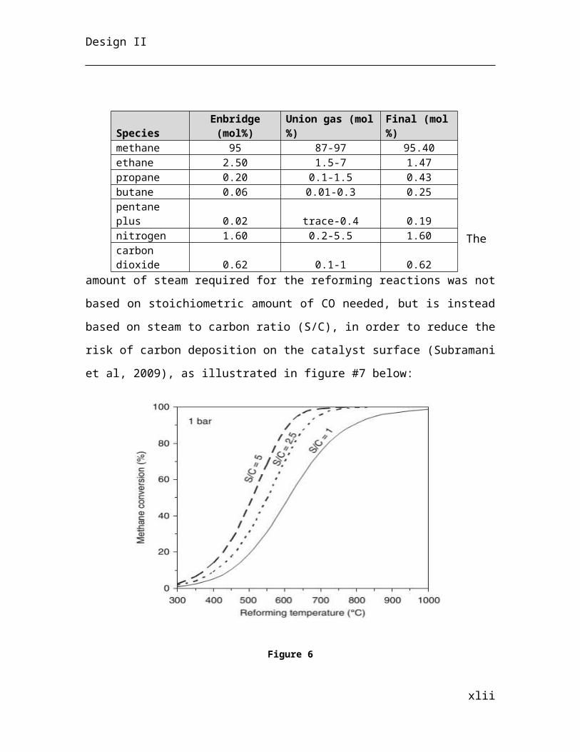
Design II
∆ T LM=∆ T A−∆ T B
ln( ∆ T A
∆T B)
Here ∆ T A is the temperature gradient at the inlet between the hot steel and cold
water, while ∆ T B is the temperature gradient at the outlet. In fact this could be switched
to yield the same result.
The temperature of molten out of the mould is better approximated by a geometric
mean as opposed to a linear average due to diffusion of heat in the molten steel. The
general geometric mean formula follows:
Geometric Mean=(∏i−1
n
ai)1n
Imagining a cross sectional picture of the mould at the outlet, the temperature at
the middle of the molten portion is still T molten ,∈¿¿ and the temperature at the interface of
the solidified stainless steel is effectively T stainlesssteel fusion. Therefore the temperature of
molten at the outlet is the following:
T moltenout=√T molten∈¿T fusion¿
Knowledge of the final molten temperature at the mould outlet allows for all final ∆ T LM
to be solved and the overall model may now be employed. The heat exchanger model
specifies that 99% can be removed as an approximation, amounting to nearly all of the
specified 20% required removal. See Appendix A.4, Table 16 for full calculations.
The strand is particularly vulnerable to buldging at the exit of the water-cooled
mould when it hits the first curvature of the arc. To ensure buldging is not an issue,
significant calculation has gone into determining the ferrostatic pressure and to ensuring
xlii
Design II
that this value is far less than the reduced yield strength of the solidified stainless steel
strand wall. See Appendix A.4 for the description and Table 15 for full calculations.
Water Spray Chamber
Secondary cooling of the stainless steel occurs as the strand passes through the
spray chamber. The strand is cooled to a uniform temperature of 400 °C and is
completely solidified upon exit of the arced spray chamber. Heat is removed by spraying
a mixture of compressed air and water, which atomises the water creating a mist. The
mist is imparted onto the slab through specialized nozzles. The use of compressed air to
atomise the water is much more efficient than reducing the nozzle diameter as small
outlet nozzle diameters tend to block easily.
Assuming the nozzles are placed all around the slab - except only 25 % of the slab faces
are directly sprayed by the mist, while the entire strand side remains open to water flux -
the chamber’s heat transfer can be evaluated. The spray chamber’s length is the first
calculation and is evaluated through knowledge of the radius of casting (or the radius due
to the arc formed in the casting process). Industry standard radii are 12.2 m (Making,
Shaping and Treating of Steel, 1998) and therefore the length of the ¼ circle and the
subsequent straight portion can be calculated as follows:
lspray chamber=πrarc
2+l straight portion
The chamber removes heat in four ways:
1. Through evaporation of the mist falling onto the strand2. Through sensible heat removal from the mist within the film boiling regime3. Through conduction of heat through water cooled rollers (which are also being
sprayed by the mist)4. Through water running down the arc on the top surface of the strand
Since the water running down the strand both increases the effective water flux
for sensible heat transfer as it passes to the lower stages of the arc, but also decreases the
impinging mist, this will be neglected. In order to neglect this, it has to be ensured that
most of the water removed should be vaporized and discharging through the top of the
xliii
Design II
spray chamber instead of running down the strand. A sensible model has been developed
relating the water flux evaporated and the water flux sprayed.
Figure 7
The model of water evaporation, with water evaporated flux on the y-axis and total mist flux on the x-axis.
The maximum water flux evaporated is 0.0025 m3/m2s, which amounts to a 0.25 cm thick
film of water sprayed per second over a unitary area. This intuition is modeled by the
following equation:
W 'evaporated=
W '
400 W '+1
Where W ' is the mist flux reaching the strand surface.
Heat removal by evaporation therefore is given by the following equation:
Qevaporation=W 'evaporated Amist spray t ¿mold ρwater ∆ Hwater ,vaporisation
A majority of the heat removed is from the latent heat of vaporization of the water
(Sengupta et al., 2004) and therefore evaporation is much more significant than sensible
heat transfer from the strand to the mist. The calculated sensible heat removal is only
0.11 %. From Figure #8, therefore, it is ideal to keep the water flux in the vicinity of 0.01
m3/m2s as this is where there is significantly more evaporation per unit impinging water
flux. The calculated water flux is 0.0101 m3/m2s.
The heat removed by sensible heat transfer is modeled with an imperial formula for the
heat transfer coefficient h:
xliv
Design II
h=α W n
Where the constants α and n are empirically determined constants from industry,
typically between 0.45 – 0.75 and 0.5 – 1 respectively. For the calculation, the average
value has been taken (i.e. α = 0.6 and n = 0.75).
Separate from the strand surface mist requirement is the mist required to cool the
rollers of the spray chamber since the atmoising nozzles are located around the entire
system of strand-compressed rollers. The conduction of heat through the water-cooled
rollers does remove a significant amount of the heat from the strand and can be
approximated through the following conductive heat transfer equation:
Q=−kA dTdr
=−k Aroller touching strand(T strand−T roller)LM
rroller
Where k is the thermal conductivity of the copper roller, the area of the strand is
estimated as 5 % of the area of the top and bottom of the strand and a log mean
temperature difference is employed due to the fact that the strand is being cooled from
the inlet of the spray chamber to the outlet. The temperature of the roller has been
estimated as one half of the strand temperature at the inlet of the spray chamber. See
Appendix A.4, Table 17 for full calculations.
Blower Section
The rack section collects the cut slabs on a roller system where they are cooled by
large blower fans situated in staggered fashion on both sides of the rack. By specifying
the number of blowers employed to be 20 (10 per side of rack) and maximum allowable
outlet temperature of the strand (90 °C), only one parameter is needed to fully specify the
entire system. By solving for the spacing between blowers, all variables are calculated
including the length of the blower section (25 m), the time on slab spends on the rack
(calculated from the roll speed to be 4.21 hours)
xlv
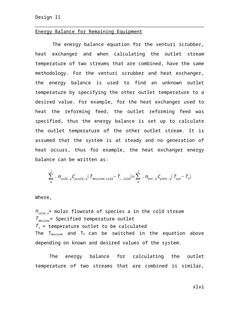
Design II
Through estimation of the heat transfer coefficient for forced-convective mass
transfer of air over a flat plate, the overall transfer of heat from the strands to the cooling
air supplied by the blowers can be calculated. Through specification of one single
industry stand blower flowrate (1.5 m3/s) and the assumption 70 % of the air is
effectively cooling the entire surface of the slabs the entire way down the length of the
roller section, the velocity of air can be simply calculated:
v= VAcross section
η
Where V is the volumetric flowrate, the cross sectional area is assumed to be the
spacing between blowers times 1 m height above the strand and η is the efficiency of air
reaching the strand on average (i.e. 70% as previously stated due to staggering the blower
placement).
With the velocity the Reynolds number can be simply calculated:
ℜ= ρvLμ
Where ρ is the density of air, L is the characteristic length, which is the length of
the strand specified by the client (as the blower is blowing parallel to the direction of the
length) and μ is the dynamic viscosity of air.
The Prandlt number can also be calculated using properties of air at 40 °C:
Pr ¿Cp μ
k
Where C pis the heat capacity of air at 40 °C and k is the thermal conductivity of air at 40
°C.
Knowing these two values we can use a standard equation for calculating the
Nusselt number of the convective air flow over a flat plate under turbulent conditions.
xlvi
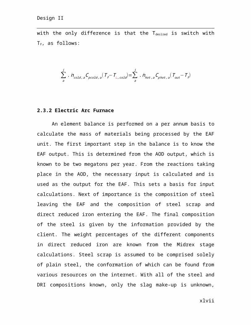
Design II
Since Nusselt number is directly proportional to the average heat transfer coefficient, this
equation can be rearranged to find the coefficient:
hx=0.0308 k
Lℜ
45 Pr
13
Now the heat rate of removed energy from the slabs can be estimated using the
convection equation with a log mean temperature difference expressing the difference
between the temperatures of the slab at the start of the blowing section to the final
temperature:
Q=ABlower section hx (T slab−Tair )LM
Therefore by knowing the average heat transfer rate across the blowing section, an
estimated time requirement can be calculated for the strand to remain within the influence
of the forced air currents. See Appendix A.4, Table 18 for full calculations.
3. Operating Philosophy
3.1 Control Theory
The following section outlines the control philosophy of the stainless steel plant,
including detailed control methodology of main operating units. An overall control
philosophy is first documented, followed by plant-wide control similarities such as pump
control and control valve control and finally the detailed control methodology of the main
operating units. All control functioning can be visualised in the P&IDs in Appendix D.
3.2 Process and Instrumentation Diagram Development
3.2.1 Overall P&ID Development
The Midrex, the EAF and the AOD units all operate in on a batch-to-batch basis.
The entire semi-batch process operates via tapping, until the ladle from the molten
xlvii
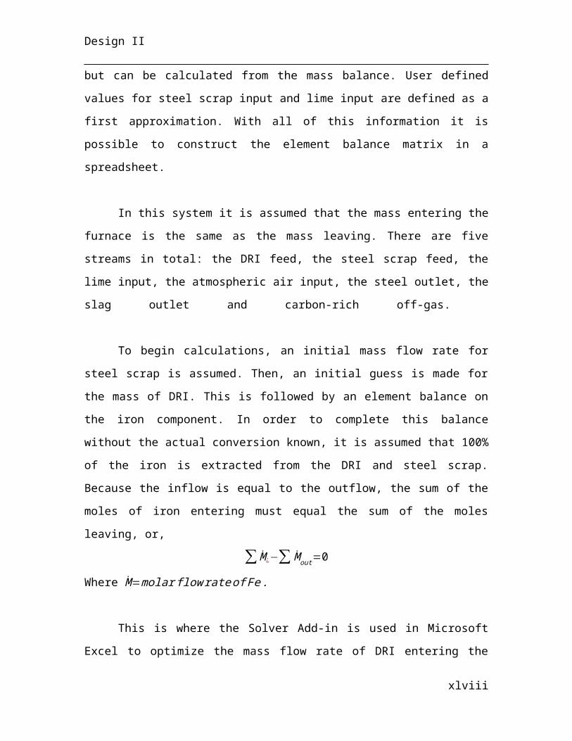
Design II
stainless steel is discharged into the tundish, where the process becomes continuous.
Fe… from Groups 1 and 2 are assumed to have fixed composition outside of the
responsibilities of Group 3. Control of the processes ensures production of 2 million
tonnes of stainless steel per annum safely from the batch to continuous process.
All vital, supporting operating units, which are required to ensure operation have
been designed with redundancies, where the operator may simply switch from one to
another at an instance of breakdown or if one requires maintenance. Controllers, for the
most part, are all wired to the central control room and indicate the measured value to the
main operating engineers. Alarms are installed at sensitive measurement sites to alarm
operators and the control room of operation at process range limits.
3.2.2 Common Unit Control Philosophy
Pumps and Compressors
The following is a typical illustration of a pump (where the control is identical to
a compressor although it is regulated by pressure control rather than flow control).
Figure 8
Figure #9 illustrates the enclosure of the pump by drain valves (with blind flanges)
directly on the lines surrounding the pump. The pump itself is drained to wastewater
treatment (WT) and is powered electrically, represented by the dashed line, by the motor
(M). A swing check valve is employed with the arrow to ensure no backflow in case of
downstream pipe blockage. The two outmost valves are for isolation purposes. The
suction side control valve is an on/off gate valve, which can be operated to restrict flow
xlviii
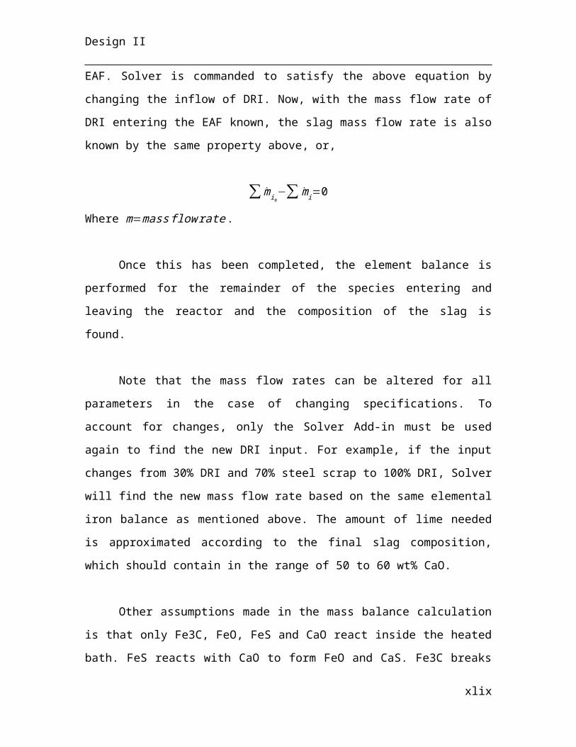
Design II
to the pump. This valve is not used for control purposes, but is especially usefully when
switching between the main pump and its redundant counterpart when maintenance is
being performed.
Control Valves
The following is a typical illustration of a control valve. A flow control valve is
shown, however the same control operation is used for a pressure control
valve.
Figure 9
Figure #10 illustrates the isolation of the control by gate valves on both the
upstream and downstream of the valve in case maintenance or replacement is required.
Drain valves with blind flanges provide the ability to drain the pipe prior to removal. A
control valve may either be fail opened (FO) or fail closed (FC), whereby on a loss of
actuated air pressure, the valve defaults to the specified position. The control conditions
downstream determine the fail selection.
A bypass line with a ball valve is connected in parallel to the control valve to
ensure processes are not halted while the valve is repaired or replaced. This valve is
closed during normal operation.
xlix
Design II
The following is a typical illustration of a level measurement and control system.
Figure 10
Figure #11 illustrates a typical level control system. Unlike other transmitters, a level
transmitter is typically isolated from the equipment with gate valves. It can be drained
via the drain valves with blind flanges upon replacement or if maintenance is required.
Notice the alarms indicating high and low levels of the measured vessel for any vital
system component.
3.2.3 Midrex Direct Iron Reduction
Midrex Shaft Furnace and Conveyor Belts
The conveyor belts make use of cascade control in order to reduce time lag. This
control mechanism is used since the amount of iron ores received from shipment will
fluctuated during the week, thus the need for a more fine-tuned control strategy. The
primary controller is a level controller located at the Midrex furnace. The level indicator
controller (LIC) will send a signal to the LIC of the charge hopper (HP) and will change
its set point value, such that immediate response take place to bring the level of iron ores
in the furnace to the desired level. The LIC of the charge hopper acts as a primary
controller to the speed signal converter (SY) set up for each conveyor belts. For each
conveyor belt, a speed transmitter (ST) sends an electrical signal to a speed indicator
controller (SIC) when the measured speed at one end the conveyor belt does not match
the set point value. The conveyor belts (including pan conveyor) contain at least four
hand stop switch (HSS) for manual control of the belt speed in the case of emergency
shutdown. The Midrex shaft furnace’s incoming syngas stream is regulated by the
l
Design II
cascade control mechanism described for the steam reformer section, however a simple
feedback loop system is set up to regulate its flowrate before entering the furnace. The
furnace’s level indicator also includes a high and low level alarm for iron ore level. The
flue gas leaving the system is regulated using a feedback loop system to regulate its
flowrate.
Figure 11
Conveyor belt and shaft furnace control are interconnected by cascade control mechanism.
Steam Reformer
It is desired to maintain the syngas temperature produced from the steam reformer
at 900oC when the Midrex process is operating. The two outlet streams of the reformer
can be used to control the upstream processes to maintain this desired temperature,
however it would be more difficult to find the appropriate set point value using the flue
gas stream. Thus, the syngas stream temperature is used to control upstream processes.
The feedback loop control mechanism was not chosen, since a temperature controller will
not respond to sudden change in flowrate due to pressure change of the inlet gas streams.
This is remedied by using a cascade control mechanism, where there is a primary
(temperature) and secondary (pressure) controller. The cascade control mechanism works
as follows:
li
Design II
A temperature transmitter (top right box in figure #13) sends an electrical signal
to a temperature indicator controller (TIC), where the measured value is compared to the
set point value of 900oC. When there is a difference, the TIC sends an electrical signal to
all three inlet stream’s pressure indicator controller (PIC) so that the set point value of the
PIC is changed, thus changing their flowrate according to the primary controller. Each
PIC is operated independently from the primary controller when their set point value is
not changed, by adjusting the inlet flowrate to the reformer to the desired value.
Figure 12
Cascade control mechanism is used to control syngas temperature.
A feedback loop system is used to control selected streams (2 more not shown in
figure #14) upstream of the reformer, since they do not feed directly into it. This would
suffice due the more thorough control mechanism set up for streams directly upstream of
the reformer. In this case, the TIC (top right box) sends a electrical signal to the pressure
signal converter to act on the control valve, when the measured syngas temperature is
different than the set point value. Since most gas streams contain flammable compounds,
drainvalves are installed to send the streams to flare, in case of emergency shutdown.
lii
Design II
Figure 13
Feedback loop mechanism is used for selected streams
Boiler
It is desired to maintain the outlet steam temperature of the boiler at 400oC. A
feedback loop mechanism suffices to accomplish this. The low time lag associated with
cascade control is not needed since the reformer feed contains enough steam for reformer
reactions to occur. The temperature transmitter (TT) sends an electrical signal to the TIC
when the outlet steam temperature deviates from 400oC. This in turn sends an electrical
signal to a pressure signal converter so that the control valve can modify the gas fuel
flowrate. It was chosen that the incoming gas fuel flowrate is adjusted instead of the
process water flowrate, since the gas fuel flowrate is proportional to the outlet steam
temperature. A pressure swing valve is installed downstream of the boiler to lower the
pressure of the stream before feeding into the reformer. In the case of emergency
shutdown, the drain valve installed sends the stream to waste water treatment.
liii
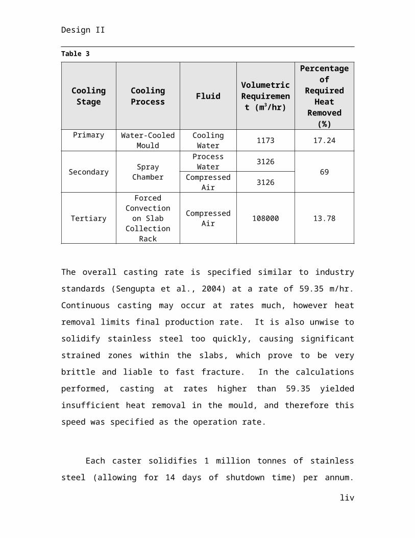
Design II
Figure 14
The boiler makes use of feedback loop control to adjust incoming gas fuel flowrate, to maintain target steam temperature.
Venturi Scrubber
Due to the high temperature of the off-gases from the EAF and AOD process
(800oC), it is important to monitor the outlet water temperature of the scrubber to make
sure boiling will not occur. It was set that the desired outlet temperature of the process
water to be the same as is given from the literature about the Midrex process: 80oC
(Fruehan et al ,1985). Referring to figure #16 below, this temperature will be maintained
using a cascade control mechanism to change the flowrate of the incoming off-gases to be
treated by both a temperature controller (primary) and pressure controller (secondary).
The feedback loop mechanism was not chosen due to its time lag, which may potentially
leave the water outlet to reach its boiling temperature. Incoming process water and off-
gas are regulated by a feedback loop mechanism to maintain flowrate at target value
(secondary control). In case of emergency shutdown, a vent to flare and drain valve to
waste water treatment is installed for the off-gas stream and process water respectively.
liv
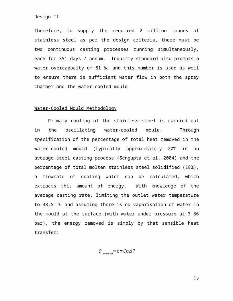
Design II
Figure 15
Cascade control mechanism is used for the venturi scrubber to ensure process water outlet does not reach boiling temperature.
Heat Exchanger
The reforming reactants are heated from 356oC to 500oC using a heat exchanger
before feeding into the reformer. A feedback loop system is used to maintain the outlet
reforming feed at 500oC, by changing the flowrate of the incoming hot stream. Only the
incoming hot stream is changed, since the cold stream would need to be changed
inversely. A more rigorous control mechanism is not needed since the reforming feed is
pre-heated to a wide range of temperature. A temperature indicator controller (TIC)
located at the outlet reforming feed sends an electrical signal to the temperature signal
converter of the hot streams entering the heat exchanger, when there is deviation from the
desired outlet temperature.
lv
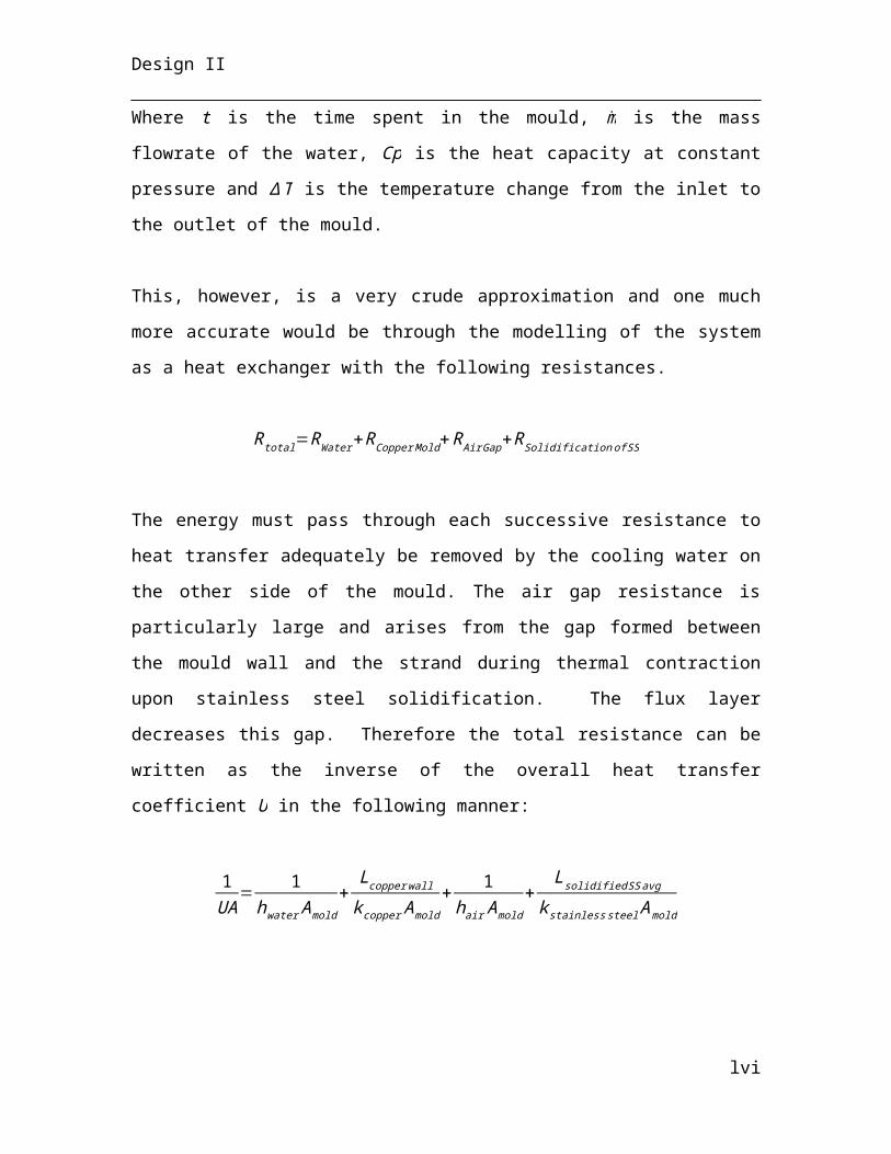
Design II
Figure 16
The heat exchanger maintains the outlet reforming feed temperature using feedback loop control mechanism.
3.2.4 Control Philosophy Electric Arc Furnace
Cooling water flow rate
Temperatures inside the electric arc furnace are above the melting point of typical
stainless steel. The furnace shell and roof and the electrodes and bus bar are all
susceptible to damage due to heating. The furnace shell is protected from overheating by
a refractory lining which decreases the heat flux into the steel shell. The roof and bus bar
are not protected by any refractory layer and a cooling system is implemented to mitigate
the occurrence of overheating.
The temperature of the water is desired at twenty-five degrees Centigrade. To
monitor this, a temperature reading is taken (TI-03-205) from the main cooling water line
and a signal is sent to the temperature transmit (TT-03-205). The measured temperature,
taken after the control valve, is sent to the flow controller (FIC-03-205), which turns the
valve position (FCV-03-205). The mass flow rate is adjusted according to the equation
for heat flux,
q=mA ∆ T
Where q is the heat flux, m is the mass flow rate of water and ΔT is the temperature
difference between the roof and the water. The area and delta T are constant, so the mass
lvi
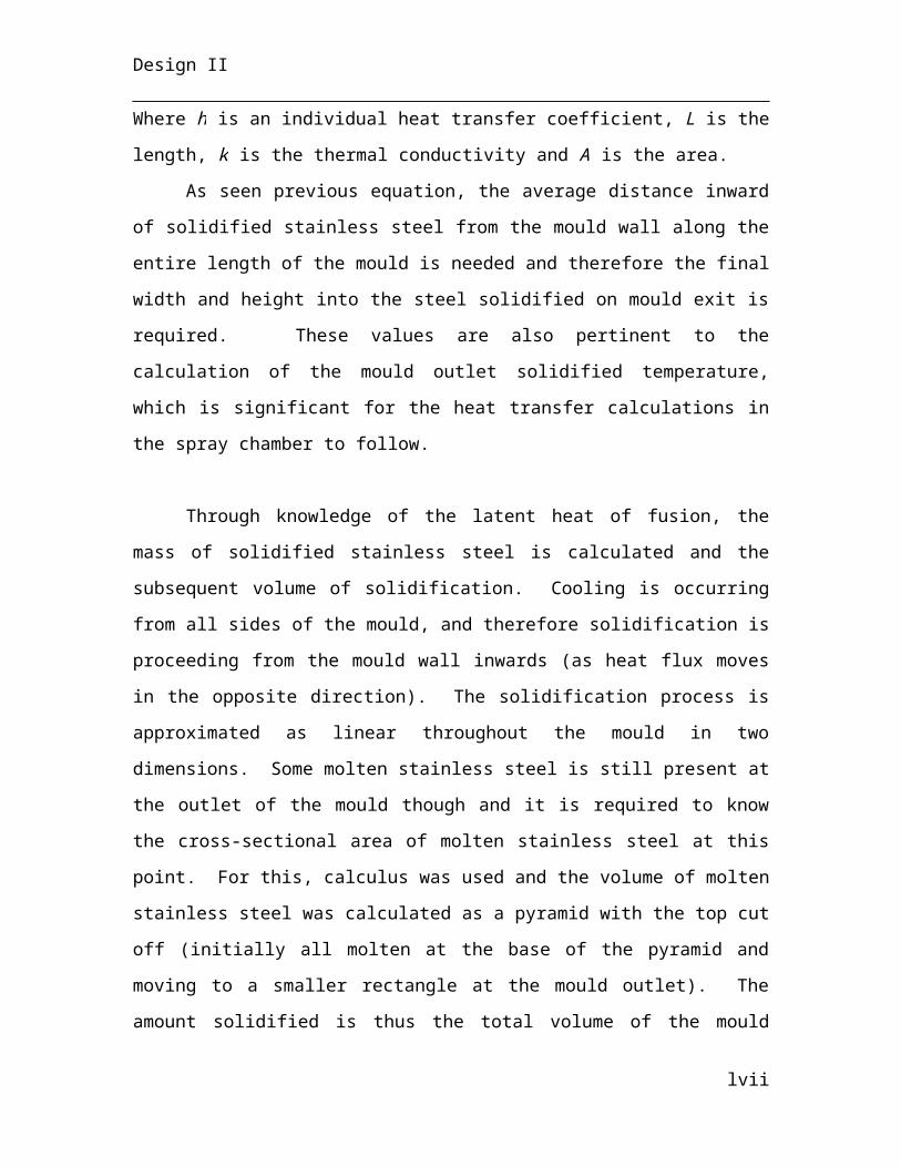
Design II
flow rate must change if the water temperature increases or decreases. The heat flux, q, is
calculated from the following equation,
q= kx
∆ T
Note that each control valve also features a bypass stream with a manual globe
valve, two drain valves, and two manual on/off valves. The flow controller sends an
electrical signal to a flow relay transmitter (FY-03-205), which sends a pneumatic signal
to the control valve. There is also a flow alarm (FAL-03-205) for when the flow is too
low, which sends a signal to the control room, warning operators that manual control
action is necessary. This setup is used for each and every control valve in the EAF
process: FCV-03-201, FCV-03-202, FCV-03-203, FCV-03-204, FCV-03-205, FCV-03-
206, FCV-03-207, FCV-03-208, FCV-03-209 and FCV-03-210.
Figure 17
P&ID for Cooling Water Flow Valve FCV-03-205
A fraction of the water is diverted to the electrode bus bar and the electrodes, as
these too reach very high temperatures due to high currents of electricity. Two additional
control valves (FCV-03-201 and FCV-03-202) control the amount of water that is
diverted to the electrodes and to the bus bar. The flow rate through each line is controlled
lvii
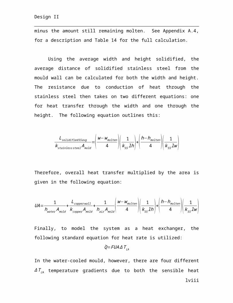
Design II
through a feedback control loop and is adjusted according to the measured temperatures.
The relationship is the same as for the main line control loop, except here the temperature
of the electrode and bus bar determine the flow rate through each respective secondary
line. Deviation from a set value for electrode and bus bar temperature either increases or
decreases flow rate to achieve a desired amount of heat absorption.
Figure #18
P&ID of Cooling Water Flow Control for Electrode Bus Bar
Figure 19
P&ID of Cooling Water Flow Control for Electrodes (top), Temperature Measurement Instrumentation (bottom)
The last feedback control loop for temperature and flow rate control is located
after the first controller, and regulates the flow rate of cooling water into the roof. The
cooling water flows through cooling panels located on the underside of the roof. The
temperature of the roof is taken by TI-03-203 and transmitted via TT-03-203 to a flow
controller (FIC-03-203). The flow controller adjusts the control valve (FCV-03-203) to
lviii
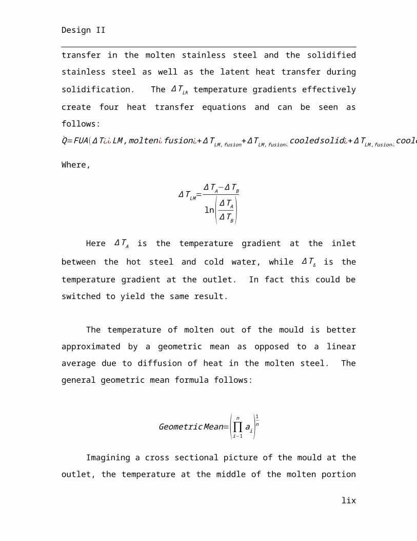
Design II
increase flow rate in the case of roof temperature higher than the desired point or
decrease if the roof temperature becomes too cool (a low roof temperature can lower
energy efficiency in the furnace bath ).
Figure #20
P&ID for Flow of Cooling Water to Roof
All control valves for the cooling water are fail open, as an instability which
causes loss of control would not cause overheating to the furnace in this way.
Hydraulic mechanisms
All moving parts of the electric arc furnace – the roof, bus bar, furnace tilting,
slag door and hot metal door – are driven by hydraulic pressure, generated by a series of
pumps (PP-03-201). The pump sends pressurized water (up to 650 bar) into a main line.
There are five lines that branch from the main line. All lines are under high pressure and
therefore pipelines must have small diameter and large thickness to prevent rupture.
The flow rate of water into pump PP-03-201 is dictated by a control valve located
upstream from the pump. It is a globe valve and its position is controlled by a flow relay
(FY-03-207) which sends a pneumatic signal based on electrical input of the flow
indicator-controller (FIC-03-207). The FIC calculates its signal from the measured flow
rate of water in the pipe. This is to prevent too much or too little water from entering the
pump, which could damage the parts. After the control valve, there is a drain valve which
is turned on manually in the case of emergency or if the pump is undergoing repairs. The
pump is driven by an electric motor which consumes 1 MW of power to drive the
lix
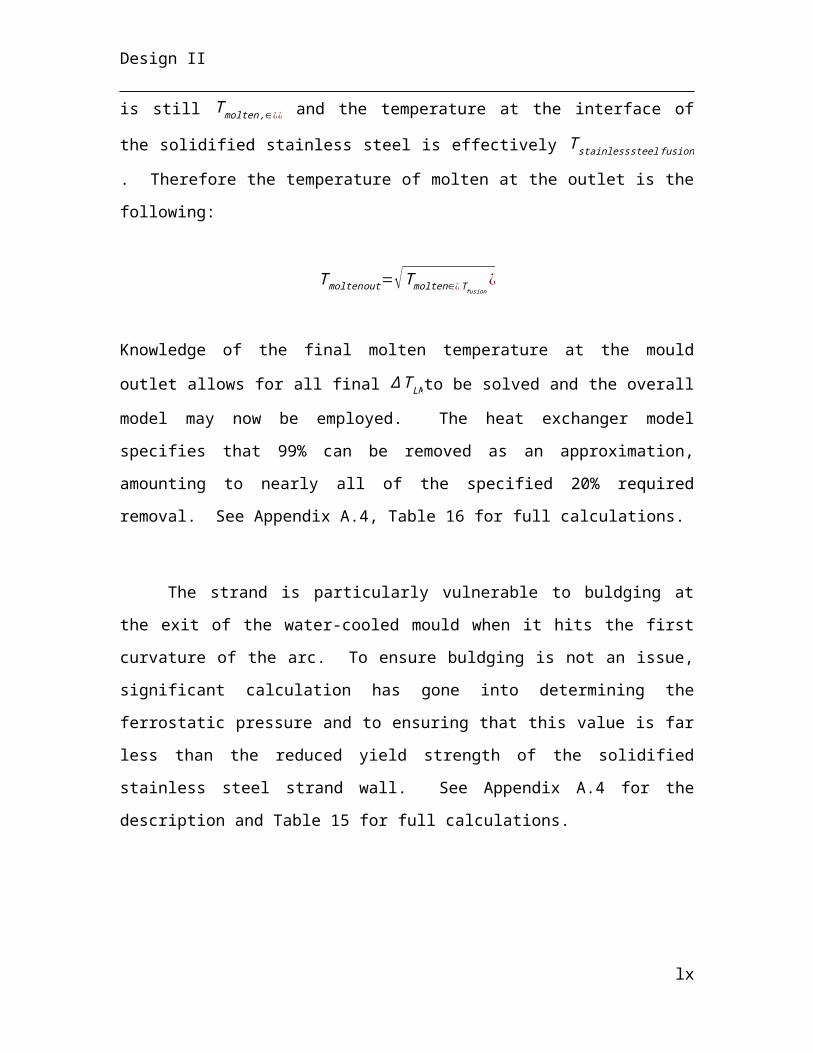
Design II
movement of the furnace parts. There is also another drain valve connected to the pump
which opens when the pressure of the outlet water is too high. The water is sent to the
wastewater treatment unity. After the pump is a second drain valve for manual operation,
a one-way check valve and a manual on/off valve. The drain valve allows water being
pumped by the system to be redirected. The check valve assures that water doesn’t enter
the pump from the wrong side, thereby causing backflow. And the manual on/off valve is
used in the case of emergency to stop flow into the furnace hydraulic system.
Figure 21
Hydraulic Pumping System PP-03-201
The first hydraulic line is connected to the roof (RF-03-201) and provides force
for moving the roof into position. A position indicator (ZI-03-203) located on the bottom
of the roof sends a signal to the position transmit (ZT-03-203), telling the controller
whether the furnace is completely covered or uncovered. The position transmit sends a
signal to the flow controller (FIC-03-204), which opens or closes the valve (FCV-03-204)
to manipulate roof movement. This valve fails closed to lock the roof in place above the
furnace.
lx
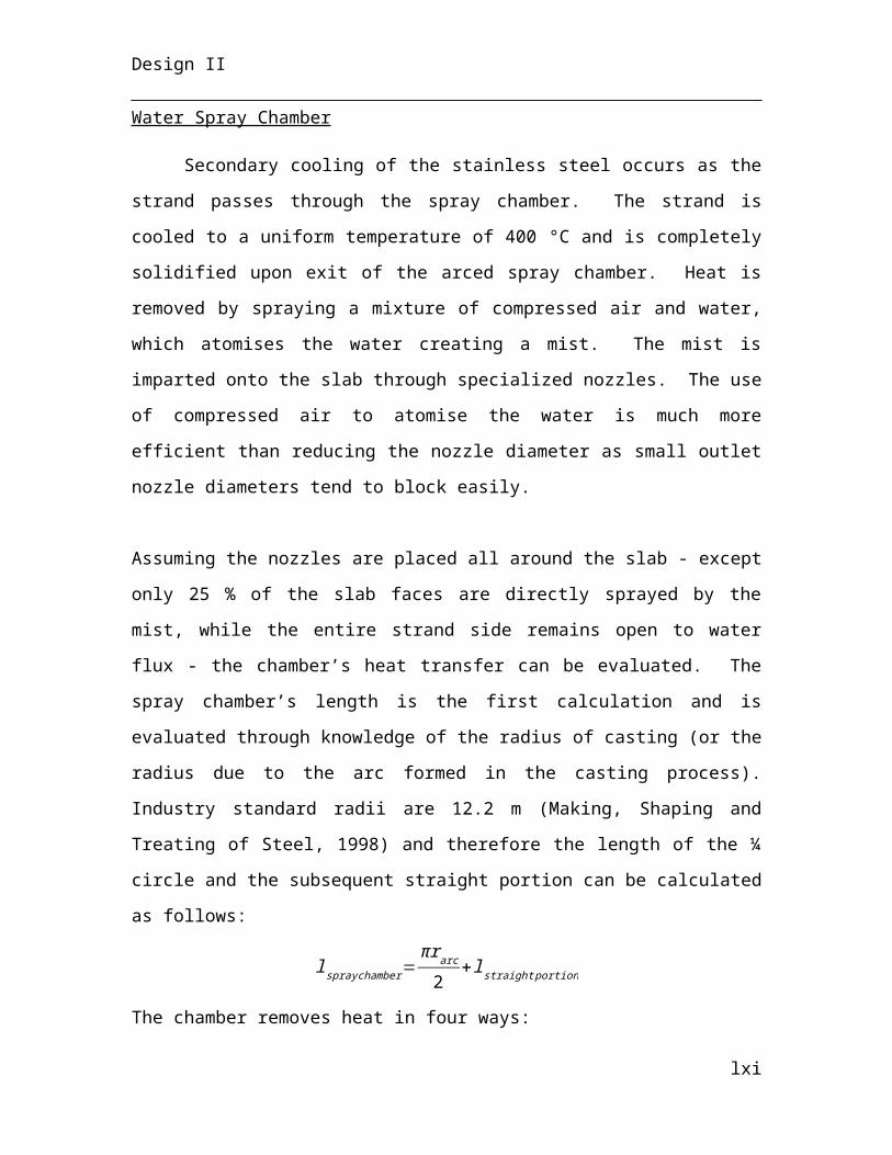
Design II
Figure 22
P&ID of FCV-02-204: Roof Position Controller
Another line connects to the electrode bus bar (BB-03-201). This is to raise or
lower the bus bar and electrodes (EE-03-201). The bus bar height is measured and
transmitted by a level indicator-controller (LIC-03-201) which sends a signal to the flow
controller (FIC-03-210) for the hydraulic line, opening or closing the valve (FCV-03-
210) to change the height of the bus bar. This control valve fails open to lock the bus bar
at its maximum height above the furnace in the case of unstable control.
lxi
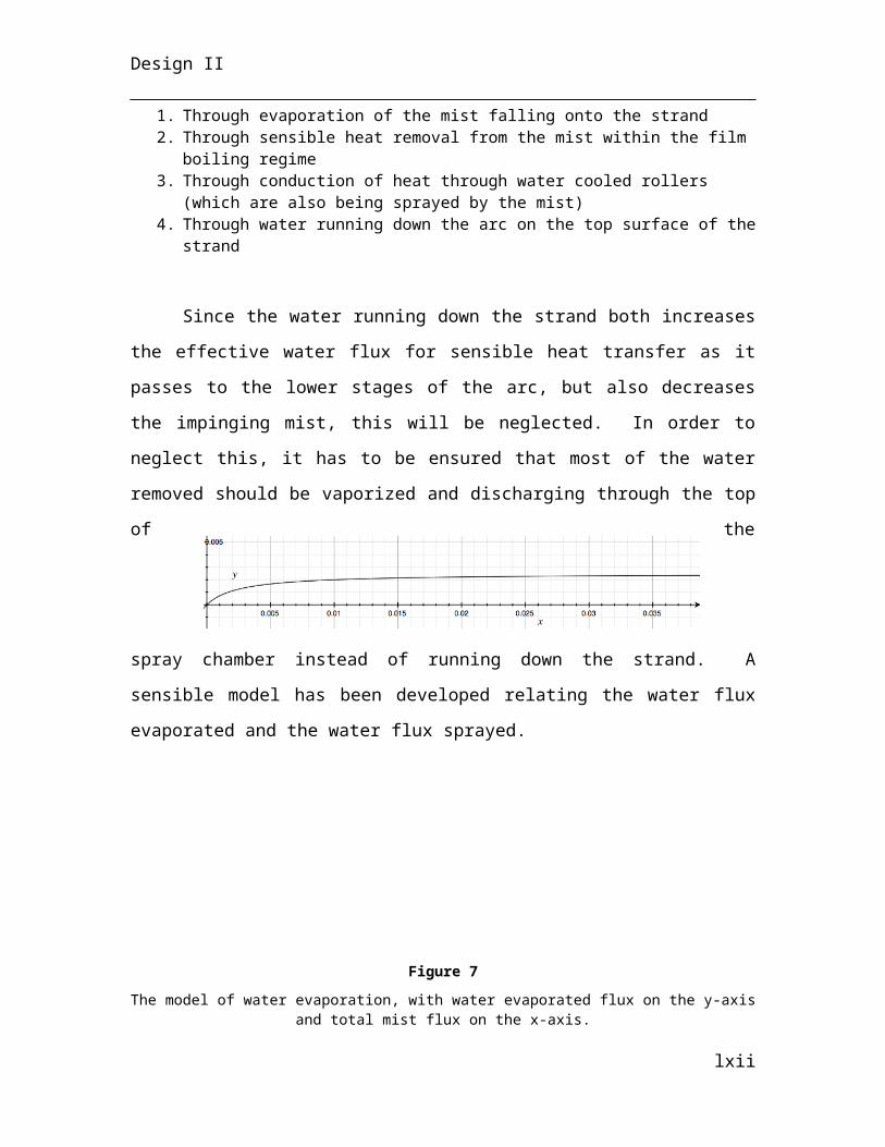
Design II
Figure 23
P&ID of FCV-03-210: Bus Bar Level Control
The tilting of the furnace for pouring material into the ladles also depends on
hydraulic force. The angle at which the furnace is tilted is measured by a level indicator-
controller (LIC-03-202). The controller sends a signal to the flow controller (FIC-03-208)
which moves the position of the control valve (FCV-03-208) to either increase or
decrease flow. To tilt the furnace in one direction, high-pressure water is pumped into the
hydraulic piston below the furnace shell. To tilt the furnace in the opposite direction, the
control valve is closed while the hydraulic pump is left on. This decreases the pressure of
the water in the piston, causing it to contract. In the case of failure, the control valve fails
open to prevent slippage of molten metal onto the factory floor.
lxii
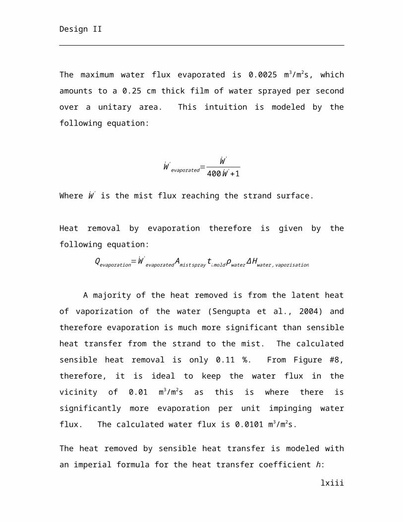
Design II
Figure 24
P&ID of FCV-03-208: Furnace Tilt Control
The final two control valves monitor the level of the slag door (part of LA-03-
202) and the hot metal door (part of LA-03-201). Level indicator-controllers are in place
for each door. The doors have two levels: fully open or fully closed. The level indicator-
controller for the slag door and the hot metal door links to the respective flow controllers.
The position of valve, either fully open or fully closed, determines the level of the
respective doors. Both control valves fail closed to keep the doors shut.
lxiii
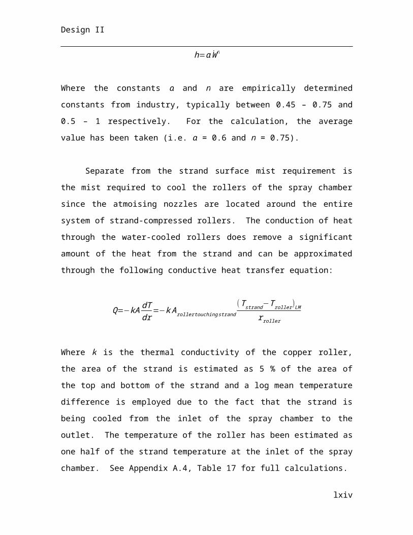
Design II
Figure 25
P&ID of FCV-03-206: Hot Metal Door Open/Close Control
Figure 26
P&ID of FCV-03-209: Slag Door Open/Close Control
Bin weighing control
One-hundred and fifty total tonnes are charged into the furnace prior to melting.
The DRI arrives on a conveyor (CV-03-102) from the Midrex unit. A bin (BN-03-201) is
located at the end of the conveyor below a chute. When the bin is empty and the control
is initiated, the conveyor turns on. When the conveyor turns on, DRI begins to flow into
the bin. As the bin is filled with DRI, it is suspended from an overhead crane (CN-03-
201). The crane is place on top of a scale, which measures the change in weight of the bin
through a level controller. When the weight of the bin reaches 100% of the required
weight of DRI, a high alarm sends a signal to the conveyor motor controller which stops
the conveyor. This alarm also sends a signal to the motor controller for the lime pebble
conveyor and lime pebble silo, after a slight time delay. First, the conveyor (CV-03-201)
is switched on. Then the hatch at the bottom of the silo (SI-03-201) is opened, emptying
lime pebbles onto the conveyor. The lime is transported to the bin, where the weight is
taken in the same way as previously mention. When the weight of lime reaches 85% of
lxiv
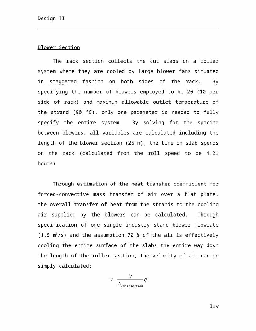
Design II
maximum, a high alarm sends a signal to the motor controller for the silo hatch, causing it
to close the hatch. This stops the flow of lime from the silo to the conveyor. When the
weight of lime is at 100%, a high-high alarm signals the conveyor motor controller to
stop.
The bin is transferred by the crane to the steel scrap weighing area. A suspended
magnet (CN-03-204), which carries about a single tonne of scrap from storage (BN-03-
203), loads the bin. As the magnet loads the bin, the weight of the bin is measured. When
the bin contents have reached the desired weight of one-hundred and fifty tonnes, the
magnet ceases its loading procedure and the bin is carried to the next transfer station
(CN-03-202 or CN-03-203).
Fan speed control
Atmospheric pressure in the furnace is desirable. The pressure increases above
this level however due to the formation of off-gas during melting. The change in pressure
is measured by an indicator-controller (PIC-03-201). The controller sends a signal to the
speed controller (SIC-03-201) for the axial vane fan (FA-03-201), which vents the off-
gas out of the furnace. This feedback control loop ensures that as pressure inside the
furnace increases, the fan speed increases to maintain a set point for pressure drop across
the fan blades. If pressure decreases, fan speed decreases.
Figure 27
P&ID of Fan Speed Control
lxv
Design II
3.2.6 Continuous Casting Section
Flux Transport Control
The following is an illustration of the flux control to the tundish:
Figure 28
Flux control highlighted.
Flux is critical to the heat transfer in the mould, to providing lubrication between
the strand and the oscillating mould wall and to minimising oxidation of the molten
stainless steel. Therefore, the level of flux powder in the hopper is constantly measured
to ensure there is a significant amount of flux entering the blow tank below, where it is
sent to the tundish. The level control, equipped with high level and low level alarms,
actuates the rotary control valve below the silo, which feeds the hopper.
lxvi
Design II
Flow control is used at the outlet of the bottom discharge blow tank to actuate
both rotary valves below the blow tank itself and below the hopper, thereby keeping a
constant flow of flux between these two units and that being transferred to the tundish via
the pneumatic conveyor. Knife on/off valves are used atop every rotary valve such that
operators may ensure the flux flow is ceased when they are to work underneath the silo,
hopper or blow tank.
A pressure transmitter in the blow tank signals the pressure controller to actuate
the pressure control valve on the recycle loop of the positive displacement screw
compressor thereby ensuring the pneumatic air is sufficiently pressurised downstream to
transport the flux to the tundish.
Molten Stainless Steel Flow Control
The following is an illustration of the rod-controlled stopper situated in the tundish.
Figure 29
Tundish level control highlighted.
The Level of molten stainless steel in the tundish is measured constantly to ensure the
following three situations do not occur:
1. Overflow – whereby there is a catastrophic discharge of molten stainless steel at 1800 °C due to the excessive addition from the AOD
2. Emptying – where the tundish becomes completely empty and casting is stopped indefinitely until the tundish is refilled with another ladle of molten stainless steel.
lxvii
Design II
3. Near empty – where the level in the tundish will be so low that the ferrostatic pressure of the molten stainless steel will not be sufficient to maintain the required casting speed.
For these reasons there are high level and low level alarms. At the level indicator must
inform the operator it is safe to dump a 150 t ladle of molten stainless steel into the
tundish, i.e. there is a sufficient empty volume. The level indicator also actuates the
stopper-controlled rod in the nozzle at the outlet of the tundish such that as the tundish
empties and the ferrostatic pressure decreases, a constant casting speed can be maintained
by increasingly lifting the stopper. The rod-controlled stopper defaults to fail-closed in
case of emergency, hindering the molten liquid from moving downstream.
Cooling Water Flow Control
The following is an illustration of the mould cooling water control strategy.
Figure 30
Cascade control of cooling water highlighted.
Cooling water used inside the copper mould for primary strand cooling is the first
of 3 essential cooling processes when casting the stainless steel. The flowrate must be
kept at a sufficient value to remove 20 % of the heat. The temperature is monitored at the
outlet and using cascade control this sets the setpoint for the flow rate of cooling water
lxviii
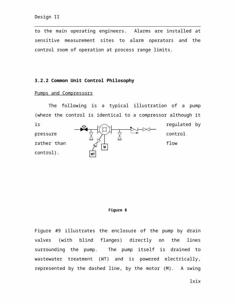
Design II
into the mould. The flowrate is also measured and the signal transmitted to this control
valve, which allows close regulation of the cooling water entering the mould. In this way
any upstream disturbances in the cooling water from Group 2 will be corrected at a much
shorter timescale, causing less variation in the essential primary cooling of the stainless
steel. There is a low flow rate alarm, which acts as a trip, signalling to the level indicator
of the tundish that a crucial water cooling supply has been reduced, which actuates the
stopper-controlled rod to close.
Mist Flow Control
The following is an illustration of the spray chamber mist control strategy.
Figure 31
Ratio of air to water control highlighted.
The mist applied directly onto the strand in the spray chamber is a mixture of air
and water, at an equal volumetric ratio. The ratio is maintained by measuring both the
flowrate of process water and of air pressure. The flow transmitter signals the flowrate of
process water and the ratio calculator sends a setpoint signal to the pressure controller,
lxix

Design II
which in turn actuates the pressure control valve to alter the flow or air. The process
water flow transmitter also sends a signal to control valve to regulate the amount of
process water entering the spray chamber. There is again a low flow rate alarm, which
signals that another critical water cooling supply has been reduced to the tundish level
controller, lowering the stopper-controlled rod via the actuator.
4. Plant Design
4.1 Equipment Sizing
4.1.1 Midrex Direct Iron Reduction
Shaft Furnace
Before sizing the shaft furnace, the residence time of the iron ores in the unit need to be
specified, since the volume of iron ores in the furnace affects the height and diameter to
be chosen. It is reported that for the largest capacity shaft furnaces in production, at about
275 tonnes per hour of DRI, require an average of 3 hours reduction in the furnace
(Hollar, 2013). However, the shaft furnace that is considered for this complex only
requires to output less than this amount. Therefore, it was chosen that the residence time,
for the capacity needed, would be 2 hours.
The inner diameter of the furnace is a parameter that is readily available in the literature.
Since the output of DRI needed for the process is close to 1 million, the recommended
inner diameter is 6.5, which is used for capacities up to 2 million tonnes DRI per annum
(Atsushi et al, 2010). The inner diameter will specify the reduction zone height of the
furnace, based on a length to diameter ratio calculated from a Midrex process.
Steam Reformer
lxx
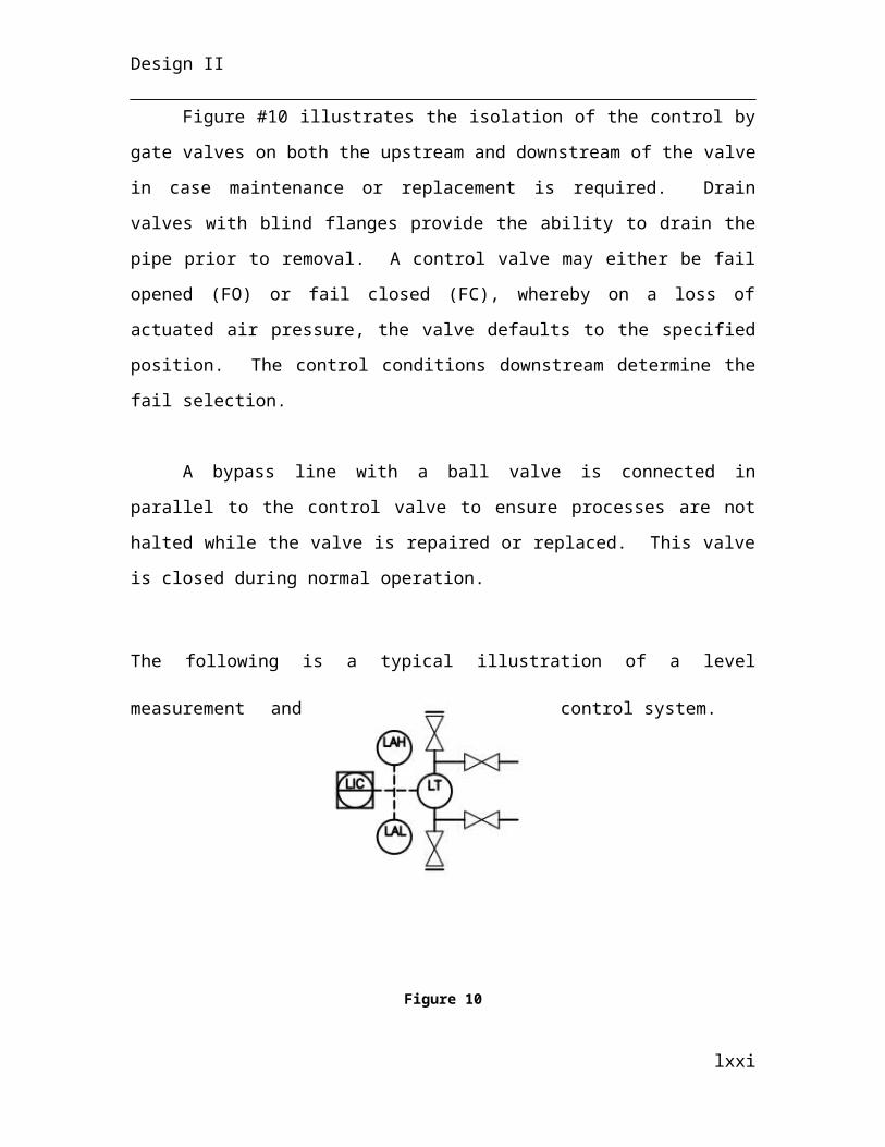
Design II
Air blower
A centrifugal air blower with forward-curved blade was chosen to transport air
into the reformer, due to their capacity to discharge the gas at very high velocity
(Maloney, 2008; perry’s handbook). The required power was calculated from the
following equation, which is derived from the adiabatic compression equation (Burton,
2002):
Pw=Qair P1
17.4 εM ε B¿
Where,
Pw= Power (kW)Qair= Air flowrate at ambient conditionsP1=Inlet pressureP2=Outlet pressureε M=Motor efficiencyε B=Blower efficiency
The flowrate used to calculate the power is the design value, which for the air blower is
set at 20% overcapacity. The dimensions of the blower are retrieved from supplier
website, after calculating the power required.
Air compressors
Due to large output flowrate required from the compressors and based on the
figure below, an axial flow type compressor was chosen for the Midrex process. The
higher pressure ratios of centrifugal compressor are not needed, since the pressure ratio
provided by axial compressor would suffice.
lxxi
Design II
Figure #32
Performance characteristics for different compressor type (Maloney, 2008).
The isentropic adiabatic compression equation was used to calculate the power
requirement of the compressor:
Pw=R T ¿
ε¿
Pw= Power R= gas constantT ¿= inlet temperature P1=Inlet pressureP2=Outlet pressureε=Motor efficiency
As in the case for the air blower, the dimensions of the compressors are given by supplier
once power requirement is calculated.
lxxii
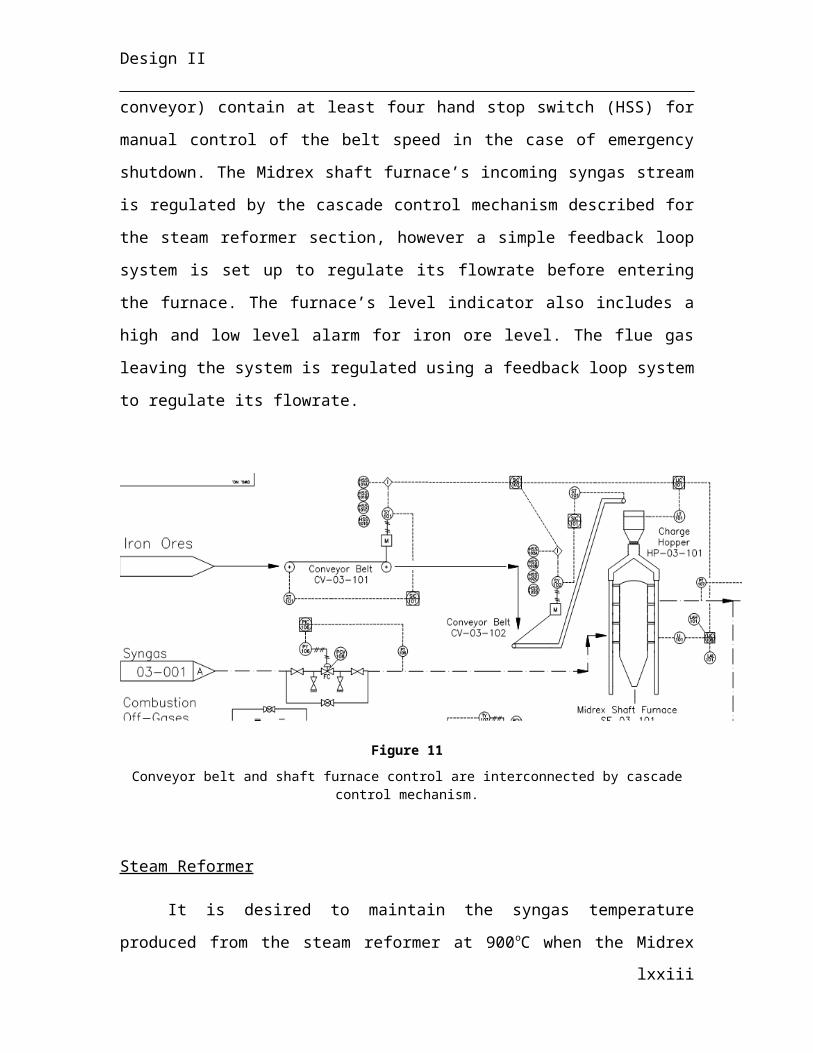
Design II
Venturi Scrubber
The majority of dust particles removed from the dirty gas stream comes from the
off-gas of the EAF process. Thus, as shown in the figure below, the average pressure
drop of 40 inches H2O across venturi scrubbers, used in common EAF processes, was
selected to design other parameters of the equipment.
Figure #33
Veturi scrubbers for EAF processes have typically a 30-50 inches H2O pressure drop.
The average size of particles to be removal from venturi scrubbers affects the
performance of the equipment and is the other parameter used to estimate the percent
removal of the scrubber. It was found that the median particle size of dust particles from
EAF process is 0.69μm (Hong-Xu et al, 2010). Thus, the percent removal can be
estimated from these parameters, as shown in the figure below, this would give a 98.5%
removal.
lxxiii
Design II
Figure #34
Venturi scrubber performance as a function of particles size to be removed and know pressure drop (EPA handbook, 1991).
The water flowrate needed was estimated from known liquid to gas ratio used for dust
particle scrubber. The energy requirement of the scrubber was estimated from the dirty
gas flowrate (EPA handbook, 1991). The dimensions of the scrubber are retrieved from
supplier specifications.
Boiler
The power requirement of the boiler is estimated from its energy balance
calculation. Both fire-tube and water-tube can be used for the process, however since
more information is readily available from suppliers on fire-tube boiler, it was chosen for
the process. The dimensions and fuel gas consumption is provided by the supplier.
Conveyor belts
2 conveyor belts and one pan conveyor are used in the Midrex process. The
values to be calculated will vary based on information that is set for each belt. Table #4
lxxiv
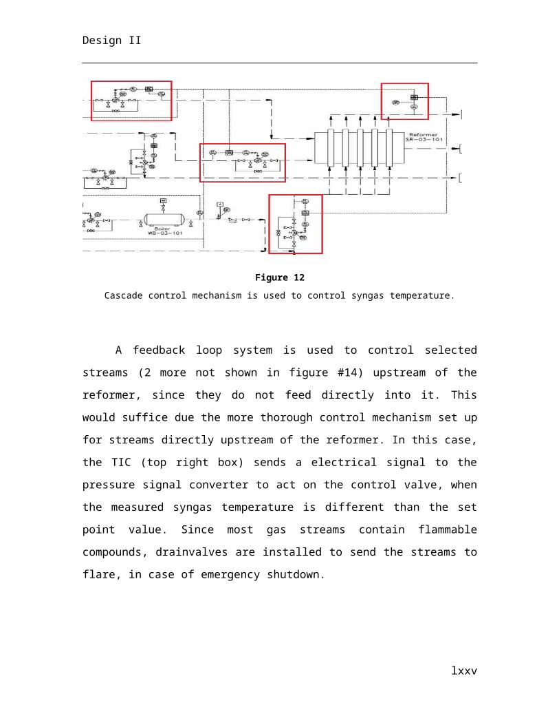
Design II
below shows the given information for each conveyor:
The specified and calculated parameters vary for the three belts in the Midrex process.
Table #4
Equipment Specified Parameter Calculated Parameter
CV-03-101 (port to plant site)
Length, speed and throughput Width
CV-03-102 (to Midrex shaft
furnace)
Width, speed, inclination and
throughputLength
CV-03-103 (pan conveyor, to EAF)
Length, speed and throughput Width
The only specified parameter that is shared by all three conveyors is the speed.
This value is set to the maximum working speed as given by the client: 1.2m/s. The
throughput is the same for the second and third conveyors, since they are responsible for
feeding and transporting the iron ores into and out of the shaft furnace. The first
conveyor’s throughput is set to the maximum working throughput, as specified by the
client: 900 tonnes per hour. This value was chosen because the amount of iron ore
received by boat shipment is not constant throughout the week and there is a minimum of
2 days of unloading to consider. This conveyor’s length has been set by the distance
between the port and plant site, while the pan conveyor’s length was chosen based on
plant layout geometry and by considering pan conveyor lengths used for Midrex
processes. The second conveyor, responsible for feeding the iron ores into the shaft
furnace has a maximum degree of inclination of 22o (Metso, 2011).
The calculation for the length or width of the conveyor will follow the same
methodology, as follows: First, the volumetric flowrate needed, based on the throughput
is calculated, as follows:
V= mρ
The width or length of the conveyor is then calculated by:
V=(w∗L)∗ν
lxxv
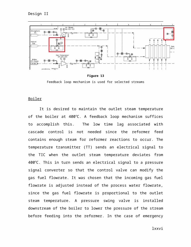
Design II
Where, ν is the specified conveyor belt speed.
Heat Exchanger
Both streams entering the heat exchanger are gas, thus this narrows the optimal
heat exchanger type to: shell-and-tube, double-pipe or compact (Hewitt & House, 1998).
Since the pressure of both inlet streams are above 1 atm, the compact design was not
chosen since it is not preferred for pressures above 1 atm. Both shell-and-tube and
double-pipe can operate to pressure up to 250 atm, making them both suitable. The
double-pipe design was not chosen, since for large scale applications they have a larger
space requirement, they are not designed for more than a single pass on tube side and
have a lower efficiency than the shell-and-tube design (Peyman, 2013). The two pass, u-
tube heat exchanger was chosen since they do not break easily when operating the heat
exchanger in conter-current flow compared to one-pass tube (Peyman, 2013).
The heat exchanger is sized from the total area of contact between the two streams:
A= QU∗LMTD∗F
Where,
Q= Heat requirement of the system (J/hr)U=Overall heat transfer coefficient (W/m2.K)LMTD= log mean temperature difference (K)F=correction factor (-)
The heat requirement is calculated from the energy balance discussed for heat
exchangers. The overall heat transfer coefficient was estimated from known values for
similar streams. The log mean temperature difference is calculated from:
LMTD=¿¿
And the correction factor is derived from graphical output, based on the two following factors:
R=¿¿
P=¿¿
lxxvi
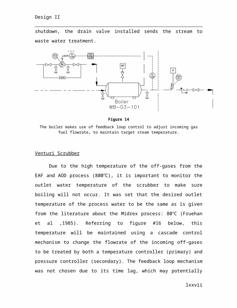
Design II
The total length for heat transfer is then calculated from:
Atotal , tubes=2 πr Ltotal
Where the radius, r, is the inner radius of the tubes. 1 inches inner diameter was picked,
since it is common value used in industries. The lengths of tubes for heat exchangers
range from 8 to 20 feet (Hewitt et al, 1998). The length of the tubes, along with the shell
diameter is picked based on tabulated value of how many tubes to use for specific shell
diameter, taking into account that the tube length to shell diameter ratio should be
between 6 to 8.
4.1.2 Electric Arc Furnace
Note that all prices are in terms of 1996 $USD and are scaled up according to the
Marshall and Swift Index. The scaling factor is 1494.5 (2014) divided by 1061.9 (1996).
The costs given in the CAPEX section are representative of the costs below
multiplied by the scaling factor. The dollar values given in this section however are
relative to 1996 $USD.
The electric arc furnace (EAF-03-201) is responsible for containing the DRI,
lime, steel scrap and molten materials. It consists of a steel shell and a refractory lining.
The refractory lining absorbs the heat flux generated by the hot components inside the
bath. This is to prevent structural deformation to the shell of the furnace. The refractory
lining is composed of a single type of brick made from a mixture of magnesite-chromite.
The layering of these bricks creates a hearth. The thermal conductivity of magnesite
chromite is 2.668 W m-1 K-1. The dimensions of each brick are 0.34 m end-to-end. The
bottom of the hearth is termed the sub-hearth and is 0.55 m thick. From the top of the
sub-hearth, the bricks are layered five-deep along the perimeter. This conformation is
1.97 m high. Above this is a thinner layer, which is only two bricks-deep along the
perimeter. This conformation is 2.83 m to the top of the furnace. The overall diameter of
the bath is 3.43 m at the top and 1.94 m at the bottom. The bath is 4.8 m in height. The
hearth is 4.8 m in diameter from side to side and 5.4 m in height. The steel shell with
surrounds the hearth is made from stainless steel. It is 25 mm in thickness and covers the
sides and bottom of the furnace.
lxxvii
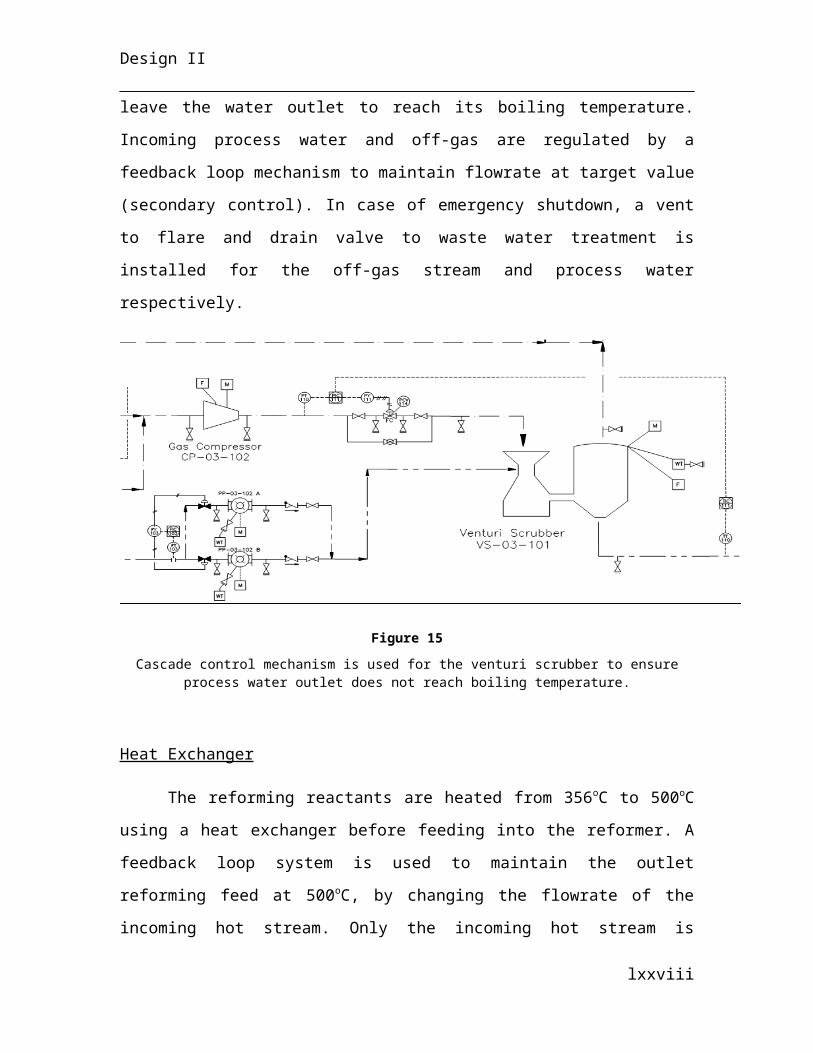
Design II
The overall dimensions for the furnace were used to calculate price. The volume
of steel required is 1.14 cubic meters. Taking the density to be 7,800 kg/cubic meter and
1,000 kg per tonne, it is found that 8.87 tonnes of steel is needed per furnace shell. At
$4,000 per tonne, a total of $35,470.15 per furnace shell is found. The volume of the sub-
hearth is 9.95 cubic meters. Using a density of magnesite-chromite equal to 2,620
kg/cubic meter, the weight of the sub-hearth is twenty-six tonnes. This is equivalent to
$104,302.89 if the value of magnesite-chromite brick is based upon $4,000 kg/cubic
meter. The roof (RF-03-201) is made of 25 mm thick steel with 50 mm thick cooling
panels covering the top surface. With diameter 4.8 m and depth 0.4 m, the total cost for
each roof is $26,758.83 including the steel plating and cooling panels. The bus bar (BB-
03-201) is taken to be a solid piece of steel 4.8 m in length, 1 m in width and 0.5 m in
depth for an equivalent price of $74,880 per bus bar. The launders (LA-03-201 and LA-
03-202) are made from magnesite-chromite brick. They are each 1 m in length and have
an area of 1 square meter. This results in an equivalent price of $10,480 per launder. Last
are the slag and hot metal doors and the hydraulic system. The doors are taken to be 30%
of the furnace shell price. The hydraulic system, not including the pump, but the
cylinders and pistons, is assumed to be 50% of the furnace price. The total price per EAF
is a sum of these individual prices and is calculated as $342,093.37.
The EAF supports three graphite electrodes (EE-03-201) for conducting current
from the bus bar (BB-03-201) into the charge. Each electrode is cylindrical, 0.6 m in
diameter and 6 m in length. Each electrode weighs 3.78 tonnes. At a price of $5064.89
per tonne, each electrode comes out to $19,161. Due to breakage and cave-ins of the
heavy material inside the furnace, electrodes are frequently replaced. Breakage of the
electrodes occurs at about one to two kilograms per heat. Sustained damage to the
electrodes lowers efficiency and can increase the time it takes for a single heat. At a
replacement rate of about one electrode per furnace for every two days, or one electrode
per day for the two furnaces, it is calculated that 298 electrodes are needed per year.
lxxviii
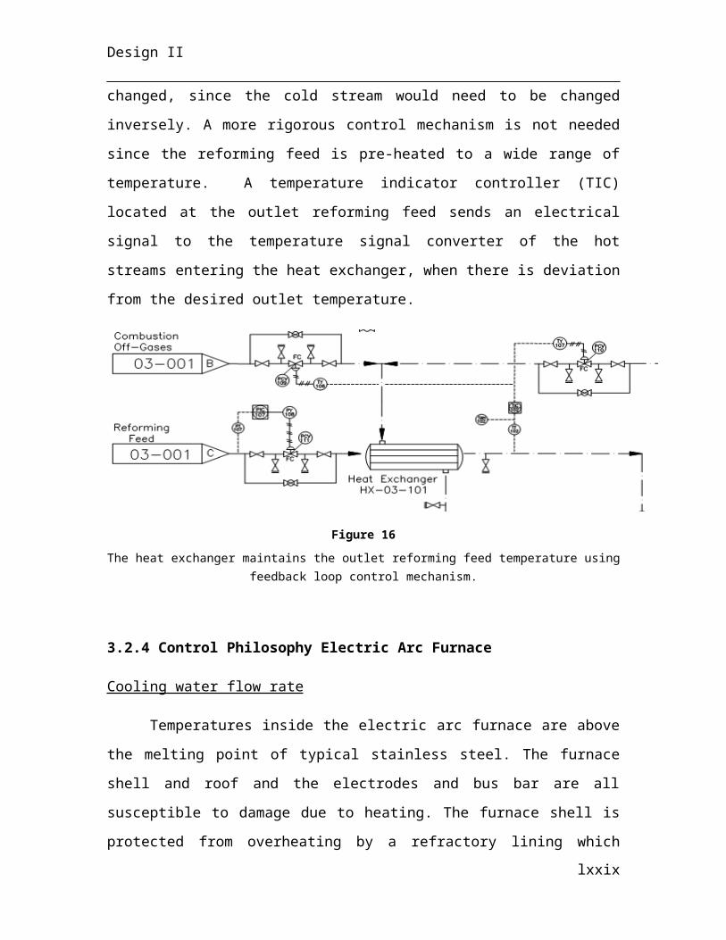
Design II
Both EAFs also need a single multiple-stage hydraulic reciprocating pump (PP-
03-201) to drive the positioning of various moving parts. The pump discharges water at
650 bar and requires 1 MW of power supply. It is constructed from stainless steel. Two
pumps are need and each is obtained at a purchase price of $1,000,000.00, for a total of
$4,600,000.00 with installation costs.
Transformers
Fifty-seven megawatt-hours are required to melt a single heat (150 tonnes) in the
EAF. The EAF runs with a power efficiency of 70%. About 0.39 MWh is required per
tonne of material to be melted (see Heat Balance). This corresponds to 57 MWh to melt a
single charge, ideally, and 81 MWh with consideration to efficiency. There are two EAFs
running simultaneously, hence a total of 162 MWh is needed. With the addition of all
auxiliary power demands, accounting for 15% of the power required for the EAFs, the
total power demand reaches 186 MWh. This power must be supplied by series of step-
down transformers. The electrical substation supplies 501 MVA for all plant operations.
The input from Hydro Quebec is 230 kV.
First in the series is a 501 MVA 3-phasetransformer which decreases the 230 kV
to 23 kV that feeds the furnaces. Following this transformer are two 81 MVA 3-phase
EAF transformers in parallel which decrease the voltage from 23 kV to 100-400 V. The
voltage is variable due to large fluctuations in current when the electrodes are initially
bore into the solid-phase charge. A second pair of step-down transformers in parallel is
required to drop the 23 kV to 11.5 kV for auxiliary power demands such as the hydraulic
pumps, conveyors, cranes, instrumentation and controllers. This is accomplished by 24
MVA 3-phase transformers.
The cost of capital for transformers is a function of MVA. For the 501 MVA 3-
phase transformers, the price is $8,350,000.00 and $110,000 for installation. Each 81
MVA transformer is $1,350,000.00 and $220,000 in combined cost for installation. The
last two 24 MVA transformers cost $400,000 each and $220,000 to install them together.
lxxix
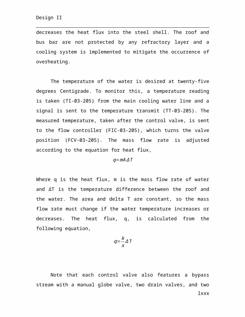
Design II
Axial Vane Fans
Three tonnes of off-gas is generated in a single heat. This gas must be evacuated
from the furnace before it can escape into the plant where it can harm workers. An axial
vane fan is placed directly above a hole in the roof of the furnace (FA-03-201). The
power efficiency of the fan is 70% and it consumes 69.3 kW for continuous operation.
Gas entering one side of the fan is above atmospheric pressure and is accelerated across
the pressure gradient (0.16 bar) into the ductwork which leads to a gas scrubber, SC-03-
101.
The axial vane fans, two of which will be needed, are priced according to their
flow rate, which is rated at 3.03 cubic meters per second. This corresponds to a price of
$3,980.00 for each fan with an installation cost of $31,910.00 on each.
Ladles
Ladles were sized according to the volume of material to be contained. The hot
metal ladles (LD-03-201/202) have a design capacity of 200 tonnes of molten metal and
133 tonnes expected. Using the density of iron, this corresponds to a design capacity of
29 cubic meters. The inside of the ladles contains a refractory lining two bricks thick, or
0.68 m on all sides, to protect the ladle shell from heat flux generated by the 1600°C
metal. The shell therefore must be constructed to have a volume of 87 cubic meters. The
height to diameter aspect ratio is taken to be 1.5. Therefore, the hot metal ladles are given
a height of 5 m and a diameter of 3 m. The carbon steel shell is 0.05 m, or 50 mm. This
corresponds to 2.05 cubic meters of steel, or 16 tonnes, which gives a price equivalent to
$111,923.95 per hot metal ladle if the price of steel fabrication is $7,000/tonne. There are
four hot metal ladles, corresponding to a total price of $447,695.80 for all ladles plus a
total installation price of $8,000 (according to capital cost worksheet).
There are also four slag ladles, or pots (LC-03-201/202). The dimensions for these
pots are according to the volume of slag to be poured into them for each heat. The pots
have a design capacity of 30 tonnes, though are expected to hold 14 tonnes per heat. Slag
is at a temperature of 1600°C, necessitating a refractory lining of two-brick thickness
lxxx
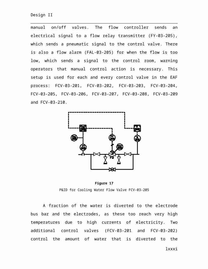
Design II
across the entire inside surface of the pot. With an aspect ratio of 1.5, the diameter is 2.33
m for a height of 4 m. The shell thickness is 0.05 m and is constructed from carbon steel.
For the design of this slag pot, 0.75 cubic meters of steel are required, or 5.75 tonnes,
corresponding to a price of $40,116.80 each if the price is $7,000/tonne of fabricated
steel. For four pots, the purchase price is $160,467.21 with a $10,000 total installation
cost.
Bins
Four bins are being used to transport DRI, lime and steel scrap – BN-03-201/202.
These bins are sized according to the volume of material within them, with a design
capacity factor of 1.5. Each is to store 150 tonnes, which amounts to 225 tonnes by
design capacity. The density of materials is a weighted average of the densities of the
different components, being 7,000 kg/cubic meter, 3,350 kg/cubic meter and 7,700
kg/cubic meter for DRI, lime and steel scrap, respectively. There is also a porosity factor
of 0.5 for the steel scrap. This corresponds to an overall density of 6,335 kg/cubic m of
material, leading to a required volume of 36 cubic meters. The aspect ratio is 1.5, giving a
diameter of 3 m and a height of 5 m. The bin is cone shaped starting 4 m below its top.
The carbon steel shell is 0.05 m on average. The volume is found through the sum of the
volumes for the cylinder and the cone. The total volume of steel required to construct the
bin is 3 cubic meters, or 22 tonnes. This can be attained at a purchase price of $153,550
each or $614,200.00 for all, with a total installation price of $153,550.00.
Lime Pebble Silos
The silos (SI-03-201) are designed to hold a maximum of 3,000 tonnes of lime
pebbles and three silos are on site. This corresponds to a volume of 896 cubic meters. The
aspect ratio is 2.0, giving a diameter of 8.5 m for a 17 m height. The carbon steel shell is
0.05 m thick and priced at $7,000/tonne. Given these dimensions, the total weight of steel
needed to construct this silo is 192.77 tonnes (taken from the density of steel, 7,800
kg/cubic meter, and volume of steel 25 cubic meters). The price amounts to
lxxxi
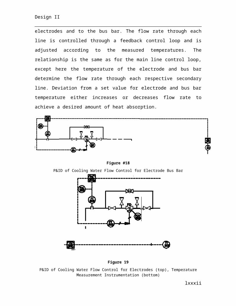
Design II
$1,349,452.32 per silo, or $4,048,356.96 for all four. The installation price is
$2,833,849.87, or 70% of the purchase cost.
Cranes
There are a total of two overhead cranes in the plant, CN-03-201 and CN-03-202.
First to be sized and priced are the beams and supports. The cranes are designed to hold
15% more than the maximum tonnage which it will be carrying, which is 225 tonnes.
Hence they both have a design capacity of 265 tonnes. For the larger crane (CN-03-202),
a beam which is 94.5 m in length, 3.5 m in width and 2.5 m in depth with a porosity
factor of 0.75 is needed to support this weight. The porosity factor indicates how much of
the volume ascertained from the dimensions above is not filled by steel but presumably
air. The corresponding volume of such a beam is 207 cubic meters of stainless steel, or
1613 tonnes if density of steel is taken to be 7,800 kg/cubic meter. The second crane
(CN-03-201) requires a beam 44.1 m in length, 3 m in width and 2 m in depth also with a
porosity factor of 0.75. This gives a volume of 66.15 cubic meters of steel or 516 tonnes.
A total of twenty structural supports are needed to support the beams. These
supports are larger than the typical structural supports used to erect the building. Each
support is 2 m in width, 3 m in depth and 22 m in height. This gives a volume of 33 cubic
meters of stainless steel per support and a weight of 257 tonnes each.
To connect the supports to the main beams, twenty support beams are required.
Each beam connects a support to the main beam. The support beams are also stainless
steel and 1 m in width, 1 m in depth and 3.15 in length. The volume of each beam is
therefore 3.15 cubic meters, or 24.6 tonnes.
The price of these beams and supports is determined from the combined weight of
steel. The main beams are $6,449,625.00 for CN-03-202 and $2,063,880.00 for CN-03-
201. The total price for crane supports is $20,592,000 and the total price for support
beams is $39,312,000.00. These values are obtained using a steel fabrication price of
$7,000 per tonne.
lxxxii
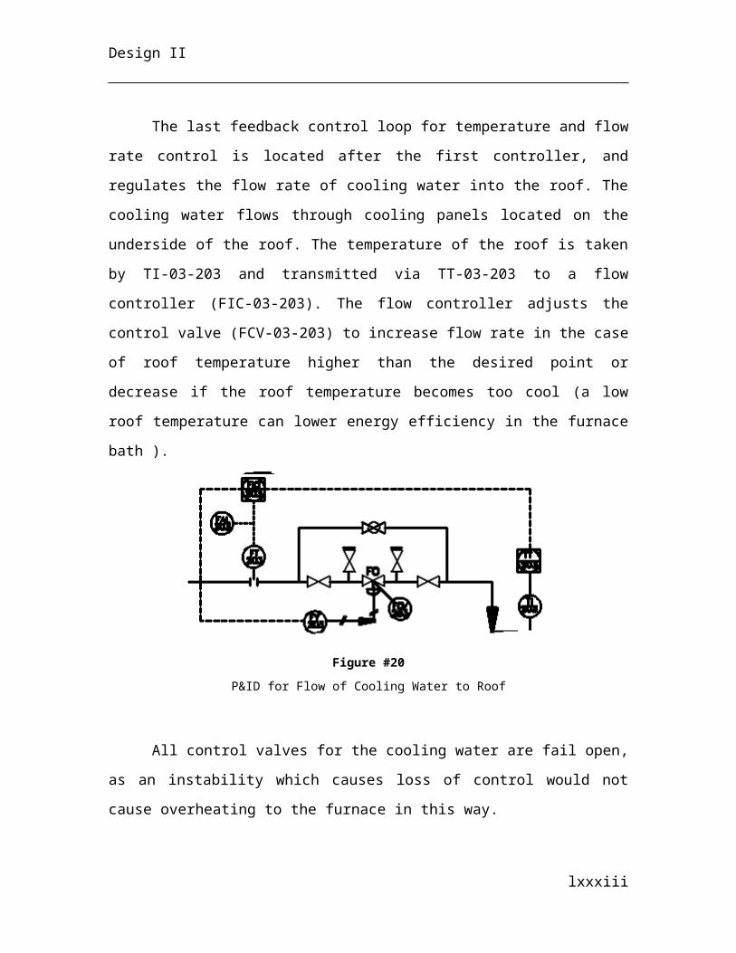
Design II
The two cranes are equivalent sizes, as both are designed to carry up to 265
tonnes. The span (clearance space needed) is 12 m. The design capacity is set to 530
tonnes per hour, which includes the weight of materials for both furnaces plus a 15%
overdesign factor. The price of each crane is dependent on the lift capacity, or 265 tonnes
and includes motors, cables, span type, hooks and electrical controls. It does not include
the main beam and tracks or supports, which were calculated in the previous paragraphs.
The purchase cost for the two cranes comes to $1,084,402.00 and with installation cost
amounts to $1,624,436.00.
Conveyors
There is one belt conveyor for the EAF unit, CV-03-201. It is used to transport
lime pebbles from the silos (SI-03-201) to the charge bins (BN-03-201). The conveyor
must handle seven tonnes of lime per hour. With a design capacity factor of 1.2, the total
capacity is 8 tonnes per hour. The conveyor is 40 m in length and 2 m wide to support the
mass flow rate of lime. The price for this conveyor is based on its area and type (belt
conveyor). The purchase cost is found to be $165,000 with an installation cost that
increases the total to $330,000.000.
Suspended Magnet
The suspended magnet (CN-03-203) is designed to be picked up by CN-03-201
for the transport of steel scrap from the storage bins (BN-03-203) into the charge bins
(BN-03-201). The magnet has a capacity of 2 tonnes of scrap per lift, and 36 tonnes per
hour with a design capacity factor of 1.2 making the final capacity 45 tonnes of scrap per
hour. It is an electromagnet, therefore the magnetic properties are induced by a current
which can be switched on or off remotely by the operator. Turning the magnet on will lift
steel scrap approximately equal to 1-2 tonnes. The required dimensions for such a magnet
are 3 m by 3 m with 1 m depth. The price of such a magnet depends on two empirical
factors, the suspension height (distance from the magnet to the crane hook) and the area
lxxxiii
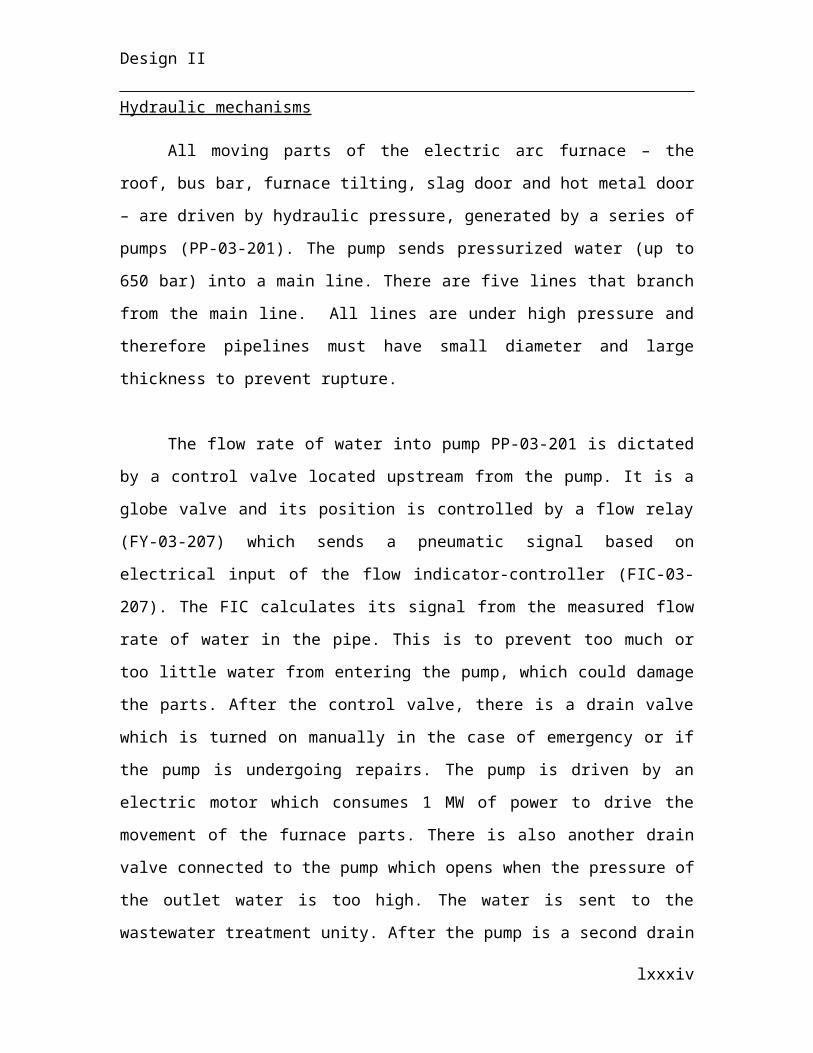
Design II
of the magnet. For one magnet with said area and a suspension height of 0.78 m, the
purchase cost is $37,841 and $61,454.00 with installation cost.
Cooling Bed and Excavator
The cooling bed (CB-03-201) is a shallow, sloped-pit in which molten slag is
dumped from the slag pots (LC-03-201). It is made by first digging a hole 5 m deep and
then filling it with 1 m of concrete. The dimensions of the cooling bed are 30 m length,
13 m width and 4 m in depth. The cost of the cooling bed is equivalent to the cost of 390
cubic meters of concrete, or $390,000.00.
The excavator, EX-03-201, is needed for the removal of slag from the cooling
bed. It has a bucket size of 0.75 cubic meters. It is designed to move 20 tonnes of slag per
hour from the cooling bed to the slag deposit (DP-03-201). It runs on diesel fuel, with an
efficiency of 0.185 cubic meters per hour. This amounts to 1,300 tonnes of fuel required
per year for a total operating expense of $461,456.00 per year.
4.1.4 Continuous Casting Section
Before sizing all equipment and unit operations, the throughput including losses
and shutdown time must be calculated. Additionally, a significant focus was specifically
placed upon the transformation of the batch production process (i.e. tapping batches of
molten stainless steel from the AOD) to the continuous casting process. The calculation
of the tonnage per day is shown in Appendix A.4, Table 12.
Tundish
The throughput is defined from the solidified casting rate, however the design
factor must be significant to ensure that the tundish never runs out of molten stainless
steel, such that the continuous casting operation stops. The design factor is specified as
2, such that two ladles can be received simultaneously by one tundish if necessary. The
lxxxiv
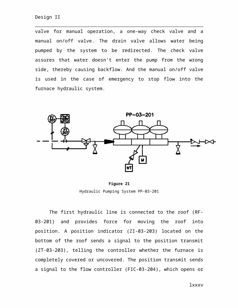
Design II
retention time is that of the throughput divided by the volume input per ladle, as that is
the target throughput of the entire system:
τ=˙V casting
V per ladle
Including the design factor, the volume of the tundish is then:
V design=2V ladle
The tundish is typically rectangular with a sloping bottom, for large continuous
casting systems and therefore the volume can be split up into two subsections, the
rectangle itself and the volume of a truncated pyramid. The volumes are calculated by
the following equations:
V rectangle=lwh V truncated pyramid=13
(l2+lb+b2 ) a
Where b is the length of the narrow end and a is the height of the truncated
pyramid. By setting the volume of the truncated portion and specifying the length and
width of the tundish, the height can be calculated knowing the required volume. The
density of the molten stainless steel density at 1800 °C as above, yielding 6799 kg/m3.
The nozzle is stopper-rod controlled and attached to the bottom of the tundish.
This allows a continuous flowrate of molten stainless steel through the shroud into the
mould, as would not be otherwise possible due to the diminishing hydrostatic pressure
atop the mould as the tundish empties. Stopper-rod head movement, either manually or
automatically, in relation to the nozzle opening dictates the discharge rate out of the
tundish through the nozzle. The nozzle is made of high purity, stabilized zirconia with a
radius of 0.15 m and a height of 0.5 m.
The shroud is submerged in the molten stainless steel in the mould, preventing
unwanted oxidation of the stainless steel between the nozzle and the mould as well as the
pick-up of suspended particles. Suspended particles may become trapped inside the
liquid steel and create unwanted inclusions in the shell and have the ability to create a
catastrophic break in the shell below the mould. It has two compounds of equal
lxxxv
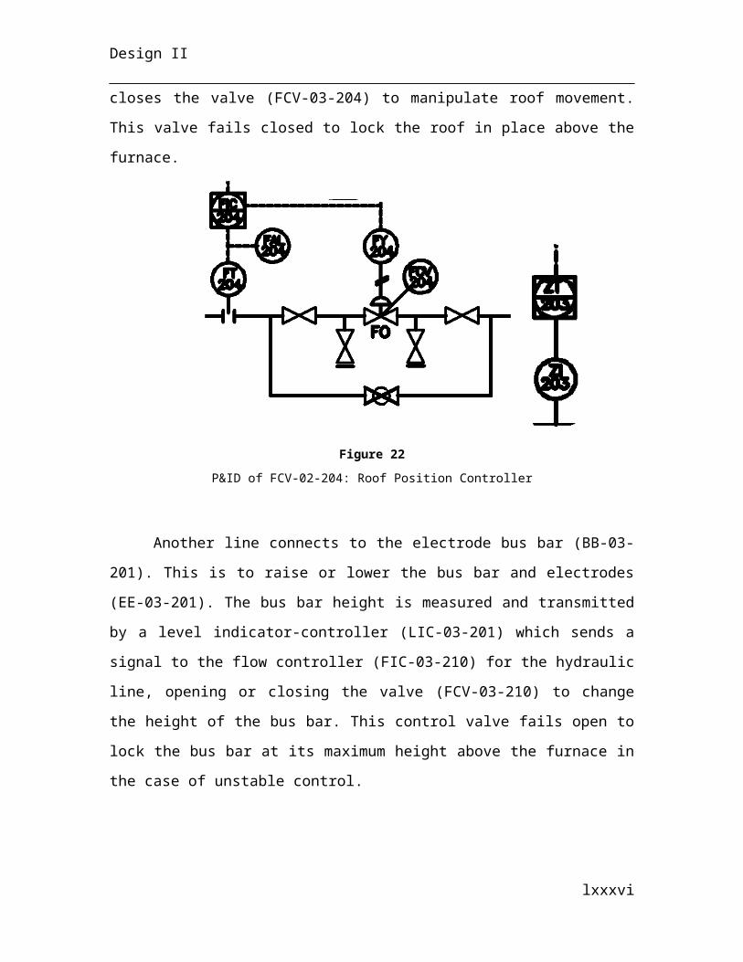
Design II
thickness, 0.05 m: magnesite graphite and fused silica/zirconia. The length of the shroud
is 0.5 m in total with 0.1 m submerged and 0.4 m remaining above the mould. Full
information can be found in Appendix B.4, Tables 19 and 20.
Flux Silo and Hopper (SI-03-401 and HP-03-401 and HP-03-402)
Literature (Shin et al., 2006) states the flux powder consumption to casting ratio
as 1.45 kg
s
1.35 ms
, therefore defining the throughput of both the flux silo and the flux hopper,
prior to addition to the tundish. The silo and hopper are both cylindrical on top with a
slanted conical shape at the bottom for dispensing. Therefore the volume is split up into
two segments, the cylinder and the truncated cone as follows:
V cylinder=π D2
4h V truncated cone=
π3 (( D
2 )2
+ D~D4
+(~D2 )
2
)~h
Where D is the diameter and h is the height of the cylinder, ~D is the diameter of
the narrow exit and ~h is the height of the truncated cone. Specifying an average retention
time, the overall required volume required may be calculated:
V design=(1.10)˙M flux τ
ρaverage
Where τ is the retention time, 1.10 represents the overcapacity design factor at
10% and the average density is the weighted average of the individual components of the
flux given in Tables 21 and 22 of Appendix B.4.
lxxxvi
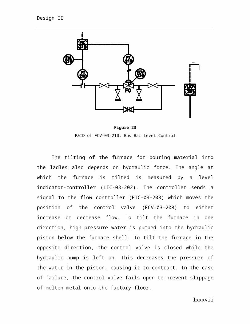
Design II
Specifying an optimum design ratio hD at 1.2, and the height and diameter of the
truncated cone, the height and diameter of the cylinder comprising a majority of the
volume can be calculated with the knowledge of the overall required volume using
solver. Full information can be found in Appendix XX, Table XX.
Oscillating Water-Cooled Mould (MD-03-401 and MD-03-402)
The water-cooled copper mould consists of two chambers: the inner chamber with
solidified stainless steel touching the walls and molten stainless steel inwards to the
middle and the surrounding water chamber, which covers the entire surface area of the
mould. The mould oscillates vertically so that the stainless steel doesn’t stick to the walls
and tear the casting skin: when the tensile forces are larger than the cohesive forces. This
is completed by a motor-driven cam and designed asymmetrically in velocity space in
such a way that the down stroke cycle moves faster than the mould (which helps to
solidify the shell) and the upstroke of the cycle is rapidly moved back to the starting
position. The heat is transferred from the latent and sensible heat of stainless steel to the
countercurrent flowing water, in a similar manner to a heat exchanger. The dimensions
of the mould are similar to industry standards (l=10 m , w=1m ,h=0.25¿, where the
mould length is situated in the vertical direction, perpendicular to the ground. The
throughput of the stainless steel is specified by the solidified casting rate, whereas the
water throughput is calculated as a required heat removal fluid with mCp ∆T assuming
there is no vaporization of the water locally at the interfacial surface:
mwater=γ ( Qremoved by mold
Cp ∆ T )
Where ∆ T is the change in water temperature, which is fed at a specified 30 °C and exits
the top of the mould at an industry standard 38.5 °C, to ensure the heated cooling water
does not exceed environmental limitations and γ is an industry standard water
overcapacity (81% overcapacity) (Making, Shaping and Treating of Steel, 1998) to
ensure there is significant water fed to all cooling components of the system.
lxxxvii
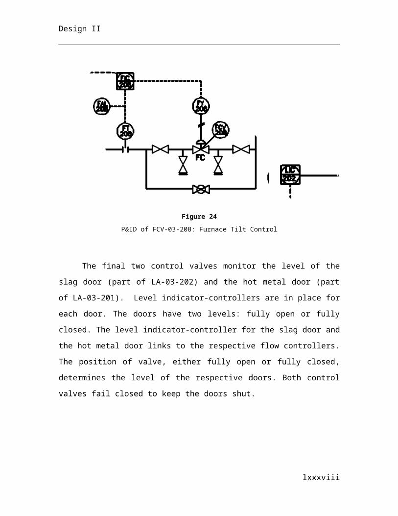
Design II
The internal wall thickness separating the water chamber to the stainless steel
mould, is a industry specified 0.04 m. The chamber width and height is a constant 0.02
m on all faces of the mould yielding a volume:
V water chamber=( w+2 w c) (h+2hc) l−lwh
Where w c and lc are the constant width and length of the water chamber, respectively.
The pressure of the water system is at 3.68 bar to ensure no surface boiling and
the average pressure in the water-cooled mould is defined by the height of molten
stainless steel above the mould plus half of the height of the mould itself creating the
ferrostatic pressure:
Pferrostatic=ρg(htundish+hshroud+hlength /2)
Where the density is the average density of molten stainless steel and solidified stainless
steel, weighted depending on their relative amounts in the mould, htundish is the height of
the tundish completely full, hshroud is the height of the shroud not submerged, and hlength /2 is
the average height of the mould.
The material of construction is the industry standard CuB-H alloy, with 99.9 %
Cu, a tensile strength of 245.09 Mpa (2 orders of magnitude larger than the average
ferrosatic pressure), a proof strength at 0.2 % elongation of 196.08 MPa and a hardness of
80 HB. Full information can be found in Appendix B.4, Table 23.
Spray Chamber (SC-03-401 and SC-03-402)
The throughput of the spray chamber is calculated as the mist required to cool the
slab to 400 °C through the direct impact of the impinging mist on the surface, which both
removes heat sensibly to the water and which also evaporates a significant layer of water
(creating a vapor layer) as well as through sensible heat transfer to the water-cooled
lxxxviii
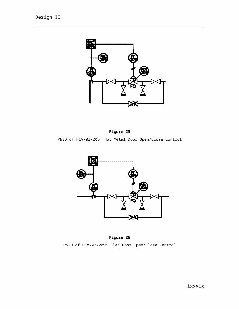
Design II
rollers which cover 75 % of the top and bottom surface area of the strand. Roller sections
of varying sizes are spaced tightly, providing support to the strand to stop catastrophic
buldging failures in a process called compression casting. The rollers control the total
strain in the slab and maintain them below a critical level of cracking and serve to remove
a small amount of heat as well through conduction.
A mist cooling technique is often employed in the spray chambers as conventional
water spraying impact can initiate surface cracks due to uneven cooling, and a reduction
in nozzle size often leads to blockages. The introduction of compressed air to pressurised
water improves heat transfer, requires smaller water throughputs (as steam is constantly
removed by the compressed air) and creates cooling uniformity to hinder strand stresses.
The atomized water is ejected through standard 1PM.013.16.17 flat fan misting nozzles
with a 1 cm diameter, which produce a water flux that overlaps. The required water
pressure is 80 psig (Iron & Steel Society of AIME, 1983) and thus from “User Benefits of
Modern Air Mist Nozzle and Seconary Cooling System Technologies” (Frick, 2003), the
required volumetric water flowrate to air flowrate ratio is unity. The amount of water,
and air alike, ejected from the nozzles is 3126 m3/hr knowing the air throughput per
nozzle, the number of nozzles is 3127 per chamber. The mixture velocity can be
calculated as the following:
vmixture=V mixture
Anozzle
Where V mixture is the sum of V water and V air and Anozzle is the cross-sectional area of the
nozzle.
A simplified compression roller set-up has been adopted from Continuous Casting (Iron
& Steel Society of AIME, 1983), whereby there are 5 zones of different sized rollers
along the arc of the spray chamber from small to increasingly larger diameters, and a
final flat zone where the rollers are the largest. Full information can be found in
Appendix B.4, Table 24.
lxxxix
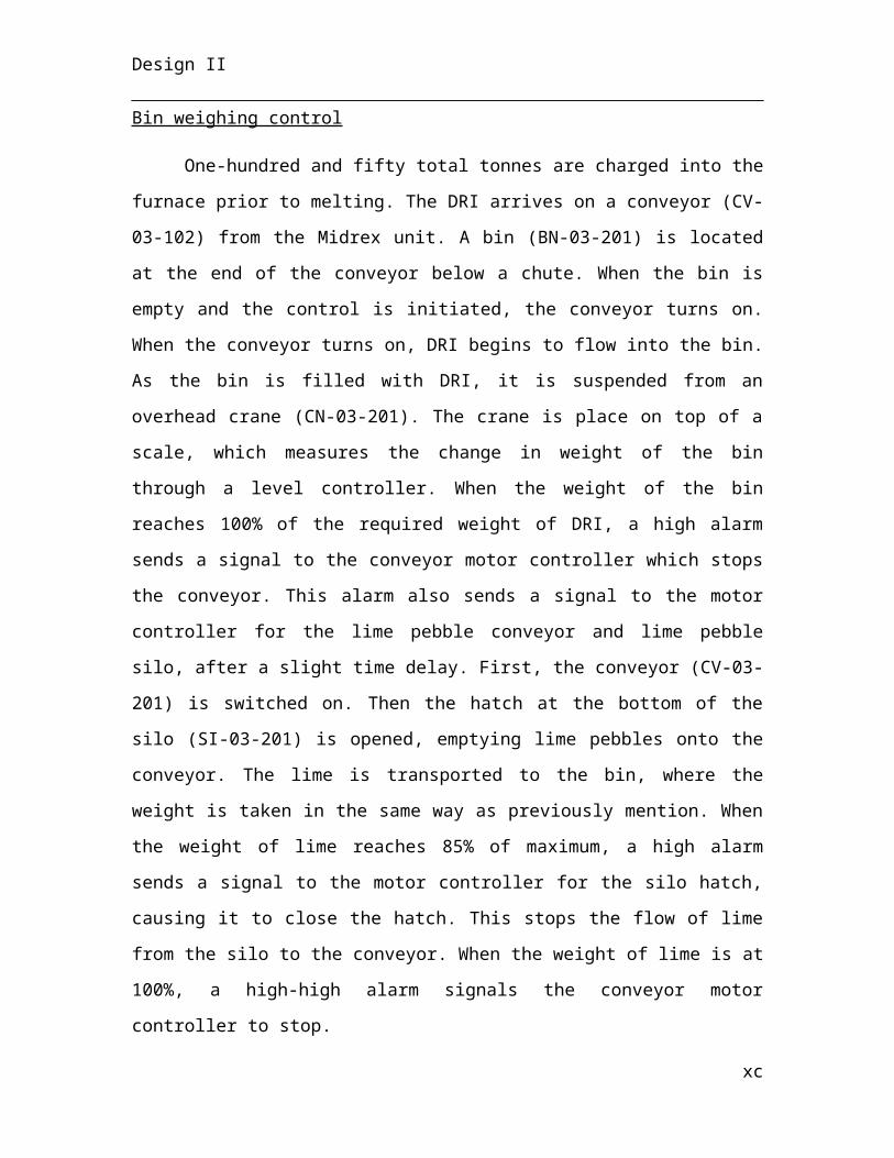
Design II
Pneumatic Conveying
Dense phase conveying systems use higher pressures than dilute phase conveying,
but require lower air flowrates (and thus lower compressor power consumption), cause
less corrosion and product degradation. Since the required flux flowrate is only 0.6 t/hr,
there is little rational in fully suspending the particles with a high air to flux ratio.
Furthermore, less air used for conveying infers less oxidation of the molten stainless steel
upon flux arrival in the tundish. Material-to-air ratios upwards of 14 (Pneumatic
Conveying Design Guide, 2004) define dense phase pneumatic flow systems. In the
calculation a value of 14 was chosen to determine the required air flowrate:
M air=M flux
14
Or in terms of volumetric air flowrate for compressor sizing:
V air=M flux
14 ρair
Setting a pressure on the discharge side of the compressor to 3 bar in order for the
downstream membrane dryer to function properly, the shaft work imparted by the
compressor required can be calculated via the Bernoulli’s equation, taking point 1 at
atmospheric conditions and point 2 to be in the line after the compressor.
H comp=Pgauge, conveyor
g ρair /flux mixture+
vconveyor2
2 g+H L
Where H comp is the shaft work imparted by the compressor, v is the velocity of the
air/flux slurry and H L are the head losses of the system due to fluid encountering
geometry changes, due to friction and to the air being pumped up to from the silo to the
second floor of the plant. The density of the air/flux mixture is simply a weighted
average of the components:
xc
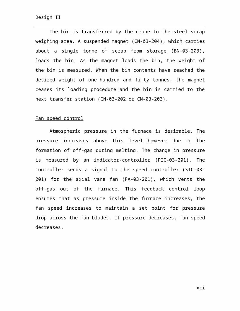
Design II
ρair / fluxmixture=∑i
2
Pi ρi=Pair ρair+P flux ρflux=1
15 (1.184 kgm3 )+ 14
15 (3093 kgm3 )=2887 kg
m3
Note the velocity of the conveying fluid is just the velocity of the air carrier, which must
be that of the required flux velocity through the pipe (vconveyor=vair ¿v flux). The velocity
of the air transporting the flux is calculated by simply dividing the volumetric flowrate by
the air, which thus requires a pipe specification chosen to be a standard 4 inches.
The adiabatic discharge temperature is given by the following equation (Plant Design and
Economics for Chemical Engineers, 2002) for compressors and fans:
T out=T ¿( Pout
P¿)(k−1)
k
Where k is the ratio of heat capacity of the fluid (cleaned air) at constant pressure to the
heat capacity at constant volume.
Rotary Screw Air Compressor (CP-03-401 A/B)
A rotary screw, positive displacement compressor has been chosen due to its
high-pressure ratio from outlet to inlet (4:1 or higher), satisfying the need for high
pressure air (3 bar) passing through the membrane filter dryer prior to being used in
pneumatic conveying. Sizing information can be found in Appendix B.4, Table 25.
Membrane Air dryer (DR-03-401)
Membrane air dryers remove water from air through a dehumidification
membrane and are often employed transform ambient air conditions into suitable
pneumatic air for actuation and conveying. A membrane air dryer was chosen due to its
ability to remove not only water vapor, but also oils often particulates from the inlet as
well as the its ability to function without any use of refrigerants or desiccants. By
xci
Design II
specifying the process flowrate, an operating pressure and a dew point suppression, a
suitable filter can be chosen to remove water vapor from the air stream. Specifications
can be found in Appedix B.4, Table 26.
Bottom Discharge Blow Tanks (TA-03-401 to 404)
Specifying the pressure in the lines of the pneumatic conveyor automatically
specifies the pressure in the blow tanks, as the compressed air flowing in the lines is
exactly the same air being fed directly into the bottom discharge blow tanks (minus any
head losses encountered by air along the way, which is assumed to be negligible due to
the lack of viscosity of air). Knowledge of the volumetric flowrate, that of the air plus
the flux, and specification of a retention time of 30 minutes, allows for the volume to be
calculated in the tanks. The temperature of the slurry can estimated by assuming the flux
remains at 25 °C and taking a weighted average of the temperatures of the flux and the
air, similar to the weighted average of the slurry density. Full information can be found
in Appendix B.4, Table 27.
Axial-Flow Compressor and Centrifugal Pump for Spray Chamber Mix (CP-03-402 A/B to 403 A/B and PP-03-403 A/B to 404 A/B)
Atomising the water used in the spray chamber is realised by the introduction of
air to the water stream prior to fluid ejection through the nozzle onto the slab. With
knowledge of the pressure of the water (Iron & Steel Society of AIME, 1983), the
volumetric ratio of water to air can be appropriately selected, which is unity at 80 psig.
Therefore the air fan must supply the same volumetric flowrate as the water required in
the spray chamber (3126 m3/s). Assuming a head loss of 15 m in the system, due to
geometrical changes (especially at the nozzle head) and the friction, the required shaft
work of the fan and the pump must is determined by solving Bernoulli’s equation taking
point 1 to be at atmospheric conditions prior to blowing and point 2 at atmospheric
pressure after nozzle ejection:
xcii
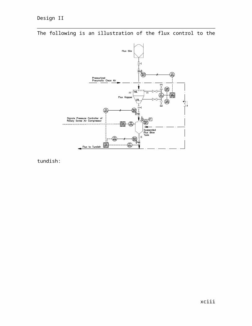
Design II
H required=vdischarge
2
2g+HL
Where H requiredis the shaft work required (in m of head) by the air fan and the centrifugal
pump, v is the discharge velocity from the nozzle head, determined by the flowrate of air
divided by the sum of the nozzles cross sectional area.
The discharge pressure can be calculated by solving a Bernoulli’s equation about
the points (1) at atmosphere for air and from the process water storage tank and (2) after
the compressor and pump. By neglecting the pressure drop across the pump and the
head losses in the pipe prior to the pump (almost insignificantly small in the pressure
calculation), the outlet pressure can be estimated:
Pdischarge=Pambient +H s ρg−vdischarge
2
2 g
Where H s is the shaft work imparted by the compressor or pump.
Single stage centrifugal compressors with an open, shrouded, low-alloy steel (such as
AISI 4140) impeller will have the ability to achieve 56 m of head, however axial-flow
compressors are typically used for imparting large shaft work onto the gas with much
higher efficiency than that of a centrifugal compressor, especially at high throughput
volumes such as is required.
A multi-stage centrifugal pump was chosen for the transport of water, from the
required head at the flowrate due to its simplicity. Centrifugal pumps provide
continuous, non-pulsating flow, while keeping capital expenditure and maintenance costs
low. Closed impellers in centrifugal pumps are advantageous because they are highly
efficient in converting power to shaft work. However, efficiency is lost when pumping
“dirty” fluids as the wear ring clearance increases. As both the process and cooling water
have low suspended solid counts at 20 ppm, closed impellers can be employed without
significant efficiency reduction.
xciii
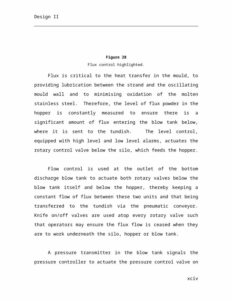
Design II
The adiabatic power required for a compressor follows the equation:
W ad=2.78 ×10⁻⁴ kk−1 F1 P1[( P2
P1 )( k−1)/ k
−1]Where k is the ratio of heat capacity of the fluid (cleaned air) at constant pressure to the
heat capacity at constant volume and F is the inlet volumetric flowrate. The required
pump power is calculated with the following equation:
W =H F ρ
3.670 ×10⁵
Where H is the head required and F is the volumetric flowrate.
Sizing information can be found in Appendix B.4, Tables 28 and 29.
Water-Cooled Mould Pump
Cooling water used to remove heat from the steel in primary mould cooling, requires an
increase in pressure to overcome both the geometry of piping and friction, but includes
the 10 m of head required to pump the water from the bottom to the top of the mould
yielding approximately 20 m of head losses. The discharge temperature of the cooling
water is a specified 30 °C and the methodology of calculating the shaft work input
required is identical to above: choosing point in the water cooling tower and point 2
at the discharge in the cooling tower.
H required=vejection
2
2 g+H L
Here vejection is the velocity at discharge into the water cooling tower, which is simply the
volumetric flowrate divided by the cross sectional area of the transport pipe (a standard
4” pipe). The discharge pressure was calculated similarly to the spray chamber
centrifugal pump, where the initial pressure was the pressure of the cooling water tank
(1.5 bar). The required pump power is the same as above.
xciv
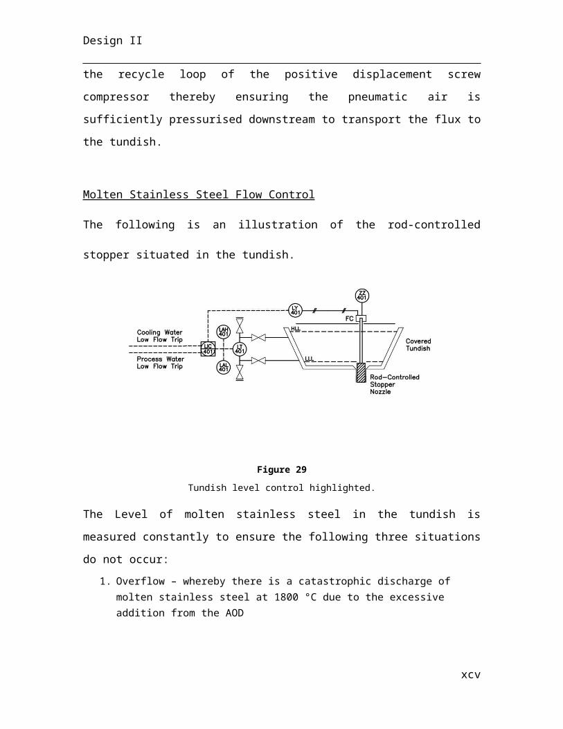
Design II
A single stage centrifugal pump has the ability to handle flowrates up to 2 x 10⁴
m3/hr below 20 m of head imparted as shaft. However, at a head of 24 m the high
flowrates in conjunction with the gravity head causes the requirement of a multi-stage
impeller centrifugal pump. Efficiencies of centrifugal pumps at high flowrates approach
80%, which is significant. Standard 4 inch piping has again been used in these
calculations. Sizing information can be found in Appendix B.4, Table 30.
Power-Driven Roller Conveyors (RL-03-401 to 458)
Powered rollers are used in section 03-006 (only after the strands have been
cut into individual slabs) and 03-007 to ensure the strands are moved away from
the casting section and to the blower / inventory section. The rollers are
individually powered as apposed to line-driven as a safety measure to ensure that
the slabs are always moved away from the casting section even if there is a failure of
one roller. Line-driven rollers are less expensive, but if they experience a
mechanical or electrical failure, the entire system must be shut down. The steel
rollers are 0.4 m in diameter with 0.3 m spacing between them, having a width of
0.25 m. The overall length of the powered roller section is 20 m in parallel to the
direction of casting until the slabs are delivered to the slab collection rack. Roll
speed is an angular velocity calculated with knowledge of the linear velocity at the
end of the roller radius, which is perpendicular to the radius. This reduces the
angular velocity formula to:
ωrollers=r × vsolidified casting
¿ r∨¿2=¿ v∨ ¿¿ r∨¿ e z¿
¿¿
Where ez is the unit vector in the z direction, i.e. longitudinally out of the cylinder
along the axis.
xcv
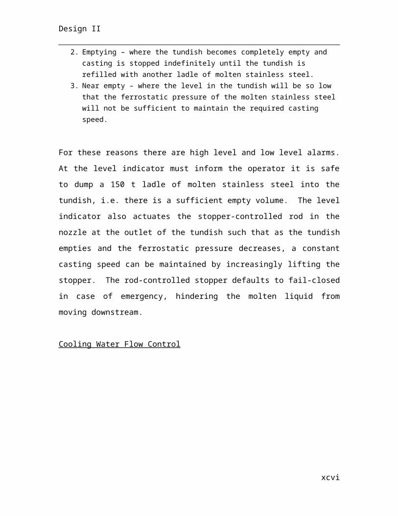
Design II
With a spacing of 0.3 m between each roller the number of rollers required can be
approximated with the following relation:
Total Length of Roller Section=n Droller+(n−1 ) Lspacing
Where n can be solved for and calculated as:
n=Ltotal+Lspacing
D+Lspacing
Full information can be found in Appendix B.4, Table 31.
Roller Conveyor Slab Collection Rack (RA-03-401)
The collection rack rollers roll the slabs in a direction perpendicular to the
casting direction, with the length equivalent to the length of the slabs themselves.
Slab throughput – the number of slabs passing per hour - is calculated with
knowledge of the width of the collection rack, 25 m:
SlabThroughput=v solidified casting
L slab
The retention time of the slabs on the collection rack must at least equal to 4.21 hr - the
time needed to yield full heat removal by the blowers from 400 to 90 °C. It can be
calculated through the specification of the width of the rack:
τ=w rack
(w ¿¿ slab)× Slab Throughput ¿
The rack width is determined in this way to ensure adequate heat removal. The steel
roller diameter is 0.4 m and the spacing between rollers is 0.3 m as above and the
xcvi
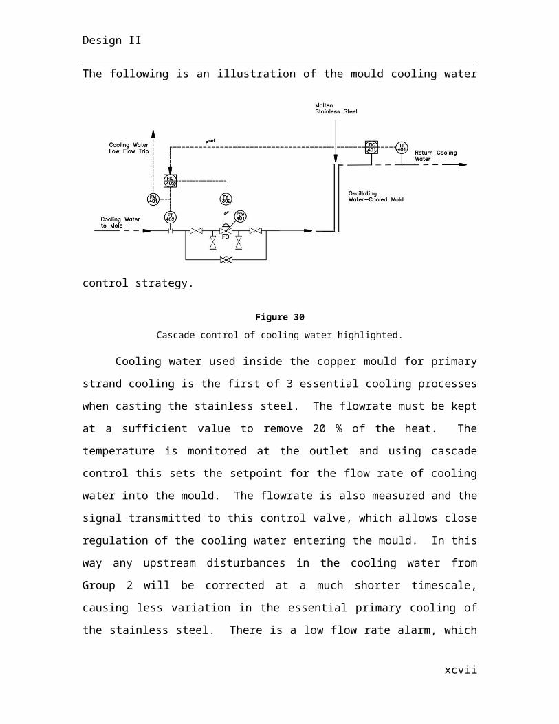
Design II
supporting rack is made of steel as well. Full information can be found in Appendix B.4,
Table 32.
Blowers (BL-03-401 to 420)
Blowers are employed for the final cooling stage to cool the slabs from 400 to 90
°C, when the slabs are on the roller conveyor collection rack, prior to being
transferred to inventory. Through the specification of the air flowrate of blowers
and the width of the rack section, a heat removal estimate can be calculated as
above and the spacing between blowers can be determined. The discharge air
temperature is calculated as for the air fans above yielding a value of 25.56 °C.
Radial blades are used in centrifugal blowers. Forward-curved blades produce a
high discharge velocity, but a lower pressure. Since the required air velocity is large and
directly related to heat transfer, the forward-curved fan seems to be a good option.
However, backward-curved blade blowers operate at higher pressures, which will of
course allow a more evenly distributed heat removal across the slabs. The radial blade
blower is a compromise between the two and therefore has been selected.
Blowers have been selected for their ability to discharge high pressure, which is
ideal for creating effective forced convection in open blowing. Fans are typically used
for moving large volumes of air thorugh ducts or pipes, but would be less well suited to
remove the remaining sensible heat from the slabs on the cooling rack. Sizing
information can be found in Appendix B.4, Table 33.
4.2 Plant Layout
Construction of the plant requires a layout of equipment including equipment
spacing. With equipment sizing known, there are several tables of heuristics that are used
for determining distances between the equipment. Equipment is placed throughout the
plant according to each unit and in consequential order according to steps in the process.
The top-down layout provides a bird’s eye view of the plant, giving a relative perspective
xcvii
Design II
of equipment sizing and spacing, as well as relating the distance between separate units.
Additionally, there are side-view layouts of each unit, which provide a height perspective
of different elements of the plant. The top-down and side-view layouts each provide a
scale for distances in the plant, with 6.3 m between pillars in the top-down view, 20 m
height of the first floor and 10 m height of the second floor.
5. Environmental Evaluation
5.1 Midrex Process
The off-gas of the EAF and AOD process are completely recycled into the Midrex
process since they contain carbon monoxide that can be used for iron reduction the shaft
furnace. There are 4 main gaseous hazard chemicals that need to be checked before
emission to the atmosphere: carbon monoxide, sulphur dioxide, phosphorous pent oxide
and silicon dioxide. The carbon monoxide limit posed the most problem, if the off-gas of
xcviii
Design II
the EAF and AOD had not been recycled into the Midrex process. However, since the
Midrex process produces carbon monoxide from the reformer, it was important to
introduce only as much reactants for syngas production as is needed for the iron reduction
to prevent excess amount of CO in the flue gas stream. The other three particulate matter
were found to be emitted at concentrations below the limit.
An emission limit for the particulate matters is also set for flue gas emission to the
atmosphere. It was found that a secondary treatment process containing a baghouse with
a 70% removal performance needs to be used installed to meet the particulate matter
limit.
5.2 Electric Arc Furnace
The furnace produces 64,604 tonnes of off-gas per year. The entirety of this off-
gas is treated by the plant’s scrubber, as it is laden with oxides that are unsafe to enter the
atmosphere. Over 20% of the off-gas is carbon monoxide, which must be reduced by the
scrubber. The remainder is nitrogen gas, which comprises about 70% and is safe to eject
into the atmosphere.
There are also 112,125 tonnes of slag produced each year. This slag is stored on-
site in a deposit temporarily. A contractor will remove this slag on a monthly or bi-
monthly basis to transport it to permanent storage. This will occur at a cost to the plant,
which is considered under slag disposal in the operating expenses. Slag experiences no
off-gassing however and does not leach any harmful matter, making it safe to store
outdoors.
The amount of cooling water needed in the electric arc furnace is reduced due to
the use of a full refractory lining. As opposed to some designs which do not incorporate a
refractory lining throughout the entire hearth, the furnaces built for this operation will
xcix
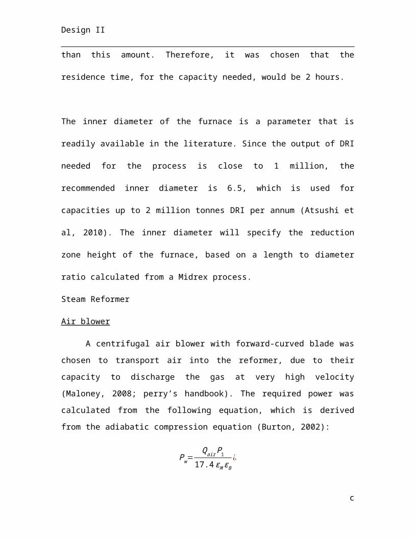
Design II
feature magnesite-chromite brick from the bottom of the hearth to the roof. Cooling water
usage is drastically reduced for this reason, by over 100%.
One last consideration is the use of hot DRI pellets instead of cold DRI. The DRI
will enter the process at 650°C, which lowers heating requirements needed by the
electrodes.
5.4 Continuous Casting
Based on available information, acetylene released in air will simply partition to
the atmosphere due to its very low boiling point where it will biodegrade by
photodegredation. It is slightly soluble in water and would rapidly evaporate. There is
little aggregation in soil and bioaccumulation in organisms is negligible. Acute toxicity
levels of acetylene to aquatic organisms are such that it has virtually no negative effect
(Chevron Phillips, 2013).
Acetylene is not acutely toxic to humans, although it is an asphyxiant, therefore a
localised release of acetylene in enclosed vicinity may cause suffocation via the
displacement of oxygen. Exposure above 2500 ppm may cause adverse affects to central
nervous system to workers in the vicinity (Airgas, 2004). To ensure all operators are able
to work safely near the manifolded acetylene tanks, area monitors will be installed in this
vicinity, which will alarm the operators of a leak. Within a 10 m radius, the area
monitors will detect the acetylene concentration in air and sound the alarm prior to
reaching the critical 2500 ppm exposure limit. Beyond this radius, acetylene is
sufficiently volatile to disperse into the air to non-critical concentrations and will
partition into the atmosphere.
The process of solidifying and cooling stainless steel in the continuous casting
section is water intensive in both the water-cooled mold and the spray chamber. To
decrease the sustainable footprint of the plant and to promote sustainable engineering, the
c
Design II
mold-cooling water amounting to 19,765,432 m3 is recycled per annum and re-used for
other cooling water operations.
The spray chamber process water is sprayed directly onto the stainless steel strand
and therefore cannot be recycled and reused by other processes. To reduce the amount of
water required from the surrounding environment compressed air is introduced in the
spray chamber with the cooling water to create a mist. This is more efficient in removing
heat due to its ability to readily vaporise and more readily break through the vapour
boundary layer at the strand surface. More efficient cooling directly reduces the amount
of process water required and discharged into the environment after treatment.
6. Cost Analysis
6.1 Capital Expenditure (CAPEX)
CAPEX is the amount of money invested into production of the plant prior to any
return on incurred costs. This sum generally includes all direct costs of purchase to
acquire the materials and equipment to run the plant as well as indirect costs, such as
contractor fees and legal expenses required to make the plant fully operational. Delivery
costs are included within unit prices of purchased equipment, however installation costs
(often a significant portion of the total cost) are added to the procurement price. All
CAPEX values are in 2014 US dollars and are given for the size and throughput of the
equipment specified in Table XX (Eqpt table). The following table highlights the capital
costs to be incurred in pre-production and provides a breakdown of each component. It is
common practice to outline certain costs as a percentage of the mechanical equipment
costs for a rough estimate.
Further detail of the costing methodology can be found in Appendix C, however a
description of the different table expenditures follows.
Direct Costs
ci
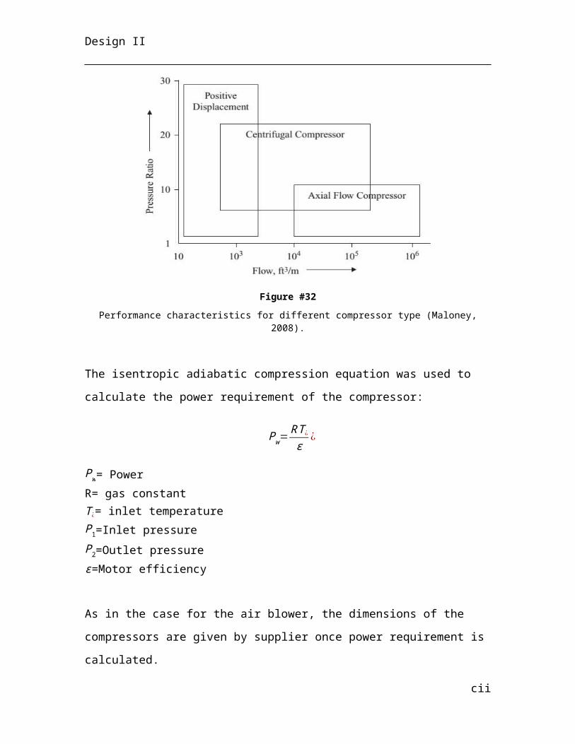
Design II
The following list outlines the direct costs:
1. Piping is typically estimated as 25 % of the pump / compressor costs as the more
pumping of fluids required the more piping needed to transport said fluids. These
costs include not only pipes, but structural materials required for pipe support.
Also included in piping costs are the valves and fittings.
2. Instrumentation and process control costs include purchase of various process
instruments such as flow meters, their installation and subsequent calibration and
their software costs to run such instruments and interface them with the control
room.
3. Electrical costs include equipment switches, general building and instrumentation
wiring, electrical device grounding and electric motors to run large machinery.
4. Building costs amount to the cost of construction materials required to build and
structurally secure the site. Included in this cost is the price of administrative and
service buildings.
5. Yard improvements are often required once acquiring a piece of land prior to
commencing construction. This cost includes the price of completing (often
expensive) landscaping projects as well as the installation of railways, walkways
and parking lots.
6. The cost of land is the procurement of the land itself from the previous owner and
includes fees for geographical surveys of the site.
7. Service facilities include expenses occurred for the installation of utilities for the
creation of steam, the pumping of water and compressed air and fuel. This fee also
includes waste disposal, fire protection and medical facilities.
Table 5
Capital Expenditure
cii
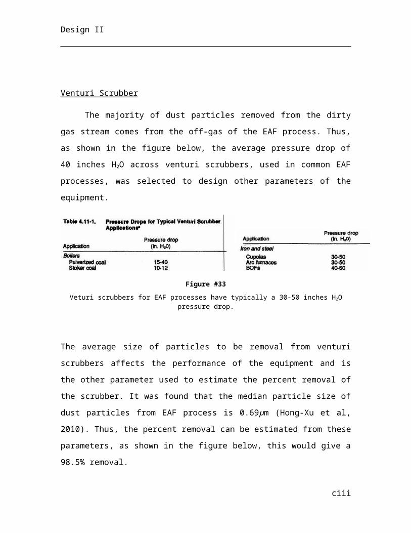
Design II
ciii
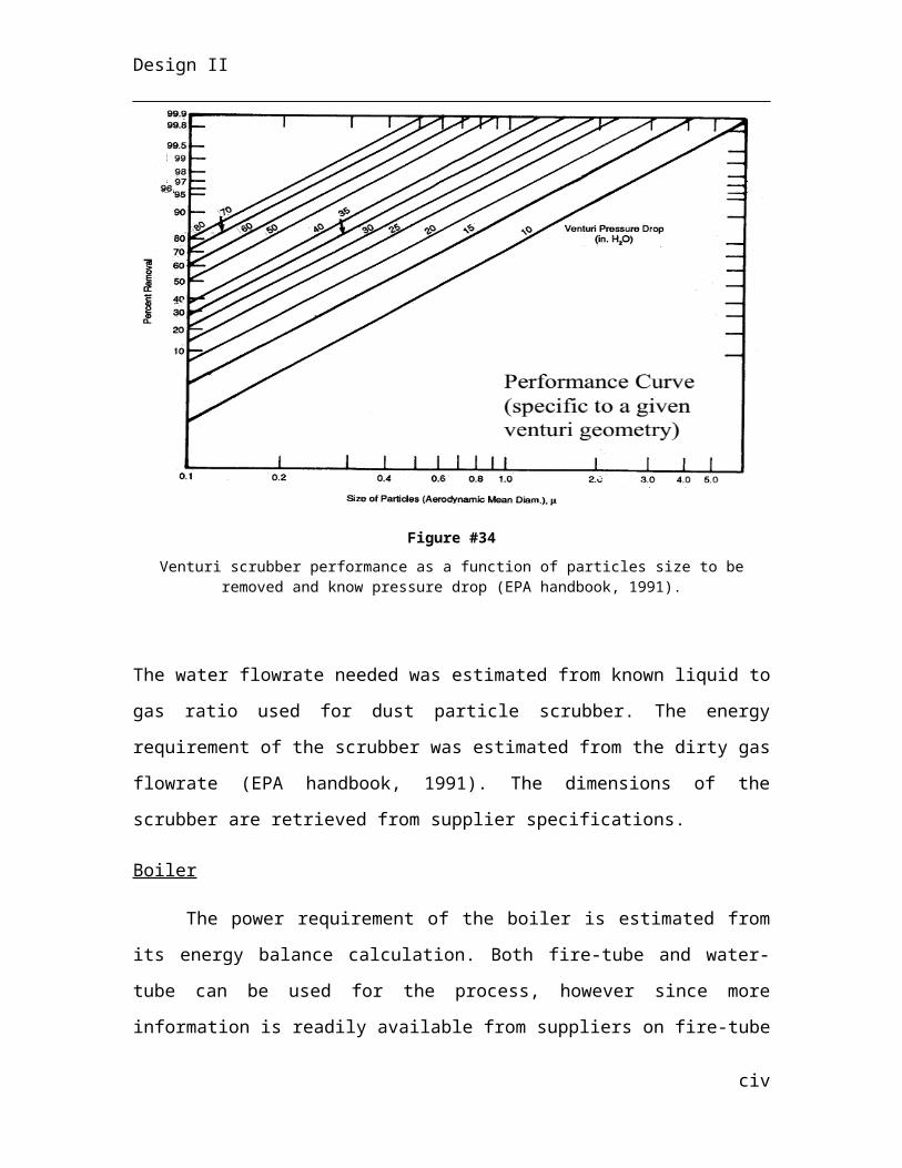
Design II
Capital Expenditure
Items
Percentage of Mech.
Equip.
Purchase Cost ($)
Installation Cost ($)
Foundation Cost ($) Total Cost ($) Remarks
s
Direct Costs Mechanical Equipment 100 $195,578,459 $104,712,727 N/A $300,291,185 Piping N/A $4,273,732 N/A N/A $4,273,732 25% of pumpsInstrumentation & Control 26 $50,850,399.29 N/A N/A $50,850,399 Electrical 10 $19,557,846 N/A N/A $19,557,846 Buildings N/A $21,144,000 N/A $5,166,000 $26,310,000 Yard Improvements 12 $23,469,415 N/A N/A $23,469,415 Land N/A $34,233 N/A N/A $34,233 Service Facilities 55 $107,568,152 N/A N/A $107,568,152 Direct Costs Sub-Total $532,354,963
Indirect Costs % of Directs Engineering and Supervision 8 $42,588,397 N/A N/A $42,588,397 Construction Expenses 3 $15,970,649 N/A N/A $15,970,649 Legal Expenses 2 $10,647,099 N/A N/A $10,647,099 Contractor’s Fee 3 $15,970,649 N/A N/A $15,970,649 Working Capital 3 $15,970,649 N/A N/A $15,970,649 Contingency 30 $159,706,489 N/A N/A $159,706,489 Indirect Costs Sub-Total 49 $260,853,932
Decommissions Cost 5% of CAPEX $39,660,445
Total CAPEX per annum $832,869,339
Total CAPEX per tonne stainless steel $416.43
104
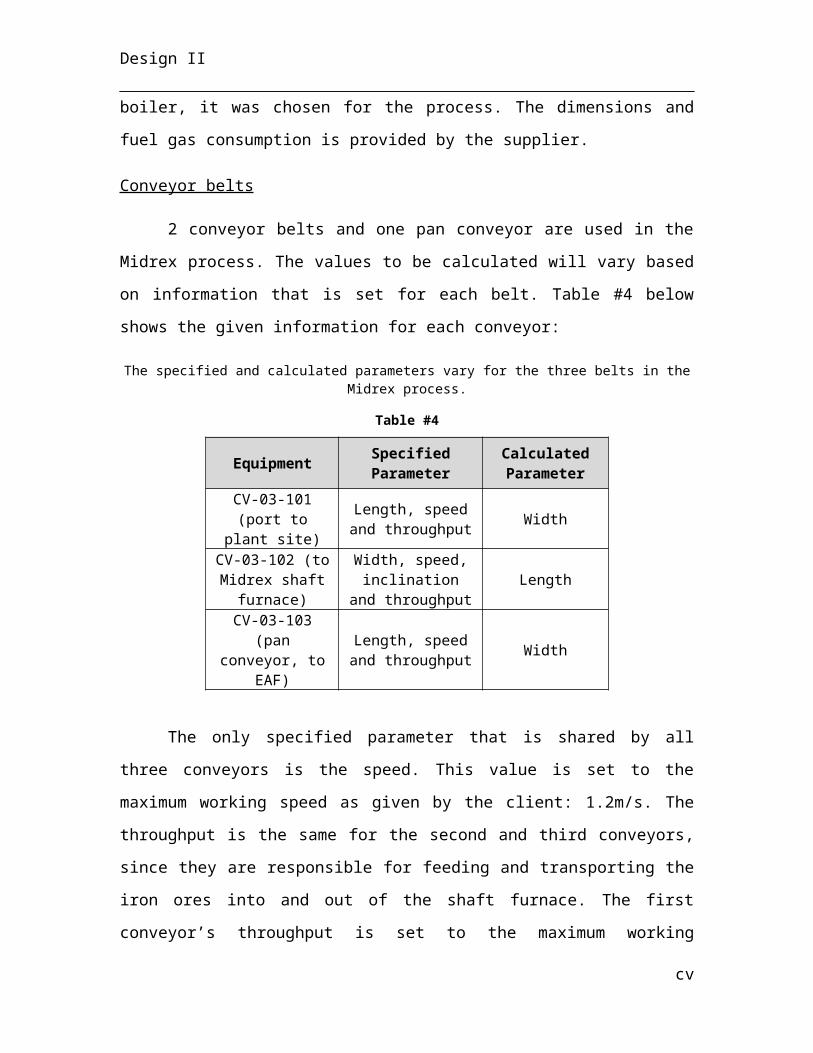
Design II
The direct costs as a percentage of mechanical equipment are as follows:
Instrumentation and process control costs: 26 % Electrical costs: 10 % Electrical costs: 10 % Yard improvements cost: 12 % Service facilities cost: 55 %
Indirect Costs
The following list outlines the indirect costs.
1. Engineering and supervision includes all the cost of all engineering fees, which
include both design and start-up of the plant.
2. Construction expenses include costs of tools used for construction and the cost of
erecting temporary construction facilities.
3. Legal expenses include the payment of lawyers to obtain licences and insurance on
the project, as well as the payment of any royalties to patents outstanding.
4. Contractor’s fees include the payment of the contractors such as a construction
group or a pluming group for a particular service.
5. Working capital includes liquid assets such as cash needed to pay for operational
expenses between the time, which the payment needs to be paid and the time at
which the money is received for stainless steel slab sale.
6. A contingency is always set up such that the project has enough money to deal with
unforeseen financial crises. This extra capital hinders delays in construction and
start up as well as providing significant reassurance of the project realisation
despite potential mishaps.
The indirect costs as a percentage of the total direct costs are estimated as the following:
Engineering and supervision costs: 8 %
Construction expenses: 3 %
Legal Expenses: 2 %
Contractor’s fee: 3 %
Cost of working capital: 3 %
105
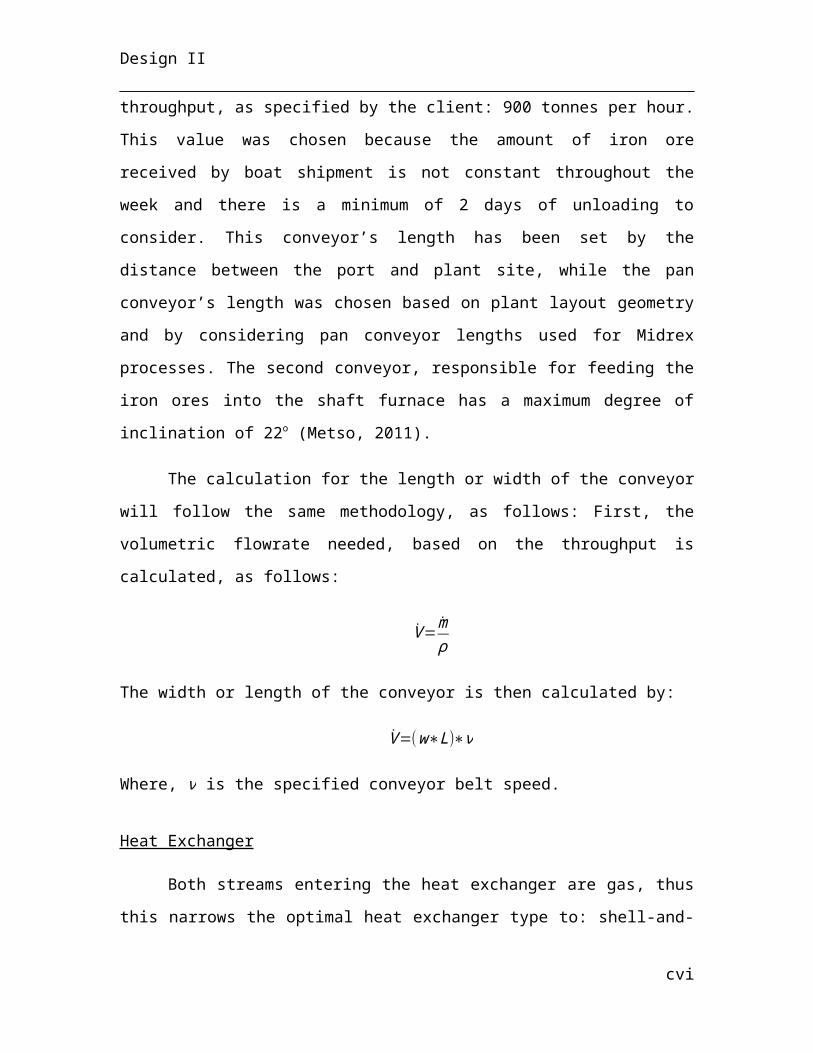
Design II
Money for contingencies: 30 %
6.2 Operating Expenditures (OPEX)
Operating expenditures are incurred after pre-production of the plant, during
operation and production. This value represents the cost of production through the
procurement of raw materials needed, required utility usage, wages of labour required to
operate the plant, waste disposal and any other supplies required to function in an
efficient manner. Annual quantities required are tabulated and multiplied by the cost
per quantity to get a total operating cost. The addition of all operating expenses yields
the overall OPEX of the plant for one year. The following table outlines the operating
expenses incurred.
Table 6
Operating costs of stainless steel production without ferrochromium included as a raw material.
106
Design II
Operating Cost
ItemsUnit Cost
($/unit)Quantity (units/an)
Total Cost ($/annum) Sub-Total ($)
Raw Materials Quick Lime t 76.00 60,000 $4,560,000 Steel Scrap t 281.52 150,000 $42,228,000 Iron Ore t 150.00 1,400,550 $182,071,540 Ferronickel t 1280.00 2,000,000 $2,560,000,000 Oxygen Nm3 0.06 99,529,560 $5,971,774 Argon Nm3 1.24 222,764,256 $276,227,677 Calcium Oxide t 110.00 161,746 $17,792,060 Ferrosilicon t 1535.00 39,212 $60,190,420
$3,149,041,471Utilities Electricity MWh 40.59 1,394,835 $56,616,364 Fresh Water t 0.20 52,672,331 $10,534,466 Diesel Fuel m3 354.96 1,080 $383,451 Natural Gas GJ 4 12,738,012 $50,952,049
$118,486,330Wages & Salaries Staff no. 100,000 15 $1,500,000.00 Operating no. 100,000 134 $13,400,000.00 Maintenance no. 100,000 52 $5,200,000.00 $20,100,000.00Supplies Magnesite-Chromite Refractory Lining t 4,000.00 786 $3,144,000.00 Graphite Electrodes t 5,064.89 1,127 $5,708,131.03
$8,852,131.03Waste Products Slag Disposal t 10.00 112,125 $1,121,250.00
$1,121,250.00Total Direct Cost $3,297,601,183
Total Direct Cost15% of Direct
Costs $494,640,177
Total OPEX per annum $3,792,241,360
OPEX per tonne stainless steel $1,896
107
Design II
6.2.1 Net Present Value of Investment
Separate costing analyses has been performed by all three Hatch groups and the
accumulated expenditure values are tabulated in Table 7. This is required to determine
the net present value (NPV) of the plant through the calculation of cumulative cash flows.
Stainless steel slabs are the primary source of revenue, but slag sale from Group 3 and
chip sale from Group 1 augment the total revenue. The following table outlines the
economic breakdown per annum of expenditures and revenues for the entire stainless
steel plant.
Table 7
Table 39 in Appendix C outlines all expenses and revenues, takes into account
depreciation of fixed assets, taxation and the time value of money to calculate the NPV of
the overall stainless steel plant. All of the assumptions used and the methods used for
calculation are also listed in Appendix C. The NPV of the project is $3,362,288,181.
6.3 Internal Rate of Return
Internal rate of return (IRR), often used to measure the profitability of an
investment, refers to the annual effective rate of return of a project discounting any
external factors. Specifically, the IRR is the discount rate at which the NPV of the
project is equivalent to zero (i.e. the invested money is exactly equivalent to the profits
received in the future – taking into account the time value of money).
108
Group CAPEX OPEX RevenueHatch 1 $789,249,937 $172,889,473 $1,142,879Hatch 2 $509,002,228 $215,782,871 -Hatch 3 $832,869,339 $3,792,471,360 $5,262,511,350
Total $5,263,654,229
Design II
This can be visualised in Table 40 in Appendix C and is solved for using solver
targeting the discount rate to a specified value of where the NPV is equal to zero. The
internal rate of return of the project is 28.71 %.
109
Design II
7. References
1 Heat Capacity, <http://en.wikipedia.org/wiki/Heat_capacity> (2 Enthalpy of Vaporisation,
<http://en.wikipedia.org/wiki/Enthalpy_of_vaporization> (3 Thermal Conductivity of some common Materials and Gases,
<http://www.engineeringtoolbox.com/thermal-conductivity-d_429.html> (4 AISI Type 304 Stainless Steel Specifications,
<http://asm.matweb.com/search/SpecificMaterial.asp?bassnum=MQ304A> (
5 Stainless Steel - Grade 304 Properties, <http://www.azom.com/properties.aspx?ArticleID=965> (
6 Air - Absolute and Kinematic Viscosity, <http://www.engineeringtoolbox.com/air-absolute-kinematic-viscosity-d_601.html> (
7 Air Properties, <http://www.engineeringtoolbox.com/air-properties-d_156.html> (
8 AIME, I. S. S. o. Continuous Casting. (1983).9 Airgas. Material Saftey Data Sheet: Acetylene. (2014).10 Frick, W. User Benefits of Modern Air Mist Nozzle and Secondary Cooling
System Technology. (Germany, 2003).
11 Mills, D. Pneumatic Conveying Design Guide 2edn, (Elsevier Ltd., 2004).12 Mular, A. & Poulin, R. Capcosts. Vol. 47 (Canadian Mineral Processors Division
of Canadian Institute of Mining, Metalurgy and Petrolium, 1998).13 Peckner, D. & Bernstein, I. Handbook of Stainless Steels. (McGraw-Hill, 1977).14 Peters, M., Timmerhaus, K. & West, R. Plant Design and Economics for
Chemical Engineers. (McGraw-Hill Science Engineering, 2002).15 Phillips, C. Product Stewardship Summary: Acetylene. (2013).16 Sengupta, J., Thomas, B. & Wells, M. in Making, Shaping and Treating of Steel
2004 Conference (New Orleans, LA, 2004).17 Shin, H.-J. et al. Measurment and Prediction of Lubrication, Powder
Consumption, and Oscillation Mark Profiles in Ultra-low Carbon Steel Slabs. ISIJ International 46, 1635-1644 (2006).
18 Fruehan, R. J. The Making, Shaping, and Treating of Steel. Pittsburgh, PA: AISE
Steel Foundation, 1998. Print.
110
Design II
Appendix A - Mass & Energy Balance
A.2 Electric Arc Furnace
Table 8
EAF Reactions.
Table 9
Steel Slag Off-Gaswt% wt% wt%
Mass Rate Tonnes/year 1,094,550 112,125 64,604
Fe 98.93 0 0
FeO 0 6.27 10.89C 0.99 0 0
P2O5 0.005 0.41 0SiO2 0.08 20.41 0.39
Al2O3 0 5.44 0.10S 0.0002 0 0
CO 0 0 26.89MgO 0 4.49 0.41CaO 0 57.09 1.00O2 0 0 0N2 0 0 60.33
Na2O 0 0.45 0TiO2 0 1.99 0CaS 0 0.07 0
MnO2 0 3.37 0
I
REACTANTS PRODUCTS1 Fe3C 3 Fe, 1 C
1 FeS + 1 CaO 1 FeO + 1 CaS
1 FeO + 1 C 1 Fe + 1 CO
Design II
Table 10
Species
MW DRI Steel Scrap Lime Air Total
INSteel Slag Off-
GasTOTAL OUT
Kg/kmol
Kmol/a Kmol/a Kmol/
aKmol/
aKmol/a Kmol/a Kmol/
aKmol/
aKmol/a
Fe55.85 16977
449260116
4 4584 0195831
96193873
6497916 97916 195831
96
C12.01 13537
67 168609 0 0152237
7902252 0 62012
5152237
7
O16.00 17050
93 0 1103309
369759
2808402
891 2430974
746296
3178160
Si28.09 38732
3 3204 25766 0416293 31222 38090
84163 416293
Al26.98 11361
7 0 7179 0120796 0 11958
81208 120796
Ca40.08 14314
9 0 1011056 0
1154204
0 1142662
11542 1154204
Mg24.31 10842
6 0 23077 0131502 0 12492
76575 131502
Na 22.99 16395 0 0 0 16395 0 16395 0 16395
P 30.97 1432 1937 194 0 3563 356 3207 0 3563
Mn 54.94 8182 45049 0 0 53231 0 53231 0 53231
Ti 47.87 27990 0 0 0 27990 0 27990 0 27990
Cr 52.00 0 0 0 0 0 0 0 0 0
Ni 58.69 0 0 0 0 0 0 0 0 0
Cu 63.55 0 0 0 0 0 0 0 0 0
N
14.01
0 0 0
2781995
0 0 0 2781995
0
S 32.07 1156 2339 2900 0 6394 64 6331 0 6394
II
Design II
Table 11
ΔH (cal/mol)
ΔH (kJ/kmol
)
ΔH (kJ/tonne)
ΔH (MWh/tonne
)
M (tonnes/h
)
Power (MWh)
Fe3C 53552 224060 1247922 0.35 29.73 10.32
FeS -21064 -88133 -1002539 -0.28 0.01 0.00
Fe 17154 71772 1285094 0.36 103.10 36.83
FeO 9194 38466 535416 0.15 3.77 0.56
P2O5 89422 374140 1317905 0.37 0.03 0.01
SiO2 26012 108836 1811523 0.50 3.05 1.53
Al2O3 45753 191432 1877520 0.52 0.75 0.39
CO 12339 51625 1843093 0.51 2.05 1.05
MgO 18591 77783 1929899 0.54 0.53 0.29
CaO 19786 82787 1476293 0.41 7.91 3.25
N2 12262 51305 1830998 0.51 4.18 2.13
Na2O 19755 82656 1333622 0.37 0.06 0.02
TiO2 18039 75477 945044 0.26 0.27 0.07
MnO2 19713 82478 982626 0.27 0.39 0.11
Total (MW) 57Weighted Average
(MWh/tonne)
0.39
III
Design II
Sample Calculations
Electric Arc Furnace Shell Sizing
STEP 1: Define necessary bath volume
Weight of material∈bath=150 tonnes
Density of materials∈bath=( 124150
tonnes)∗(70 %∗7000 kgm3 +24 %∗7700 kg
m3 +2%∗2650 kgm3 +2 %∗5740 kg
m3 )+(50 % porosity∗18150
tonnes∗7700 kgm3 )+( 7
150tonnes)∗3350 kg
m3 =6335 kgm3
Mass per heat=150 tonnes∗1000 kgtonne
=150000 kg
Volume per heat=1500006335
=24 m3
Arbitrary Numbers :
Height :diamter ratio=1.4 ;
Basin :vertical wallratio=0.41(EAF is acylinder with a deeptorispheroidal basin)
Basindiameter :Top diameter ratio=0.405
Bathheight=4.8 m
Bathdiameter=3.43 m
Height of bath above basin=2.83
Height of basin=1.97
IV
Design II
Volume of Basin=π3∗(2 hR2−(2 a2+c2+2aR ) ( R−h )+3a2 csi n−1( R−h
R−a ))=π3∗(2 (1.97 m ) ( 4.80 m)2−(2 (0.0972m )2+(0.8505 m )2+2 (0.0972 m ) ( 4.80 m )) ( 4.80 m−1.97 m )+3 (0.0972m )2 (0.8505m ) si n−1( 4.80m−1.97 m
4.80 m−0.0972 m))=90 m3
Volume of top=π ( D2 )
2
h=π (3.43m )( 14 )(2.83m )=26 m3
Totalbath volume=116 m3
Volume of Hearth ( Bath+Refractory Lining )
Brick thickness=0.340 m ;
Brick layer∈top=2 bricks ;
Brick layer∈basin=5 bricks
Height of Subhearth=0.56 m
Diameter of Topwith Bricks=3.43 m+4∗0.34m=4.8m
Volume of top= π4
(4.8 m )2 (2.83 m)=51m3
Volumeof Basin
¿ π3∗(2 (1.97 m ) ( 4.80 m)2−(2 (0.0972m+2∗0.34 m )2+ (0.8505 m+2∗0.34 m )2+2 (0.0972m+2∗0.34 m ) ( 4.80 m) ) ( 4.80 m−(1.97 m ) )+3 (0.0972 m+2∗0.34 m )2 ( 0.8505m+2∗0.34 m ) si n−1( 4.80 m−(1.97 m )
4.80 m−(0.0972 m+2∗0.34 m ) ))=180 m3
Total hearthvolume=231 m3
V
Design II
Shell thickness=0.025 m;
Total Height with Subhearth=5.4 m;
Total Diameter=4.85 m
Total volume of steel=π4
( 4.85 m )2 (5.4 m )− π4
(4.80 m )2 (5.4 m )=2.04m3
Cost of steel shell=2.04 m3∗(7800 kgm3 )( 1tonne
1000 kg )( $7,000tonne )=$111,384
Total volumeof refractory lining=231m3−116 m3=115m3
Cost of refractory lining=115m3(2620 kgm3 )( 1 tonne
1000 kg )( $ 4000tonne )=$1,205,200
Transformer Pricing
Cost for 330 MVA 3−phase transformers=$500,000
Cost for 130 MVA 3−phase transformer=$ 500,0003
=$166,667
Cost for 1501 MVA 3−phase transformer=501 MVA30 MVA
($ 500,000 )=$ 8,350,000
Cementite (Fe3C) Energy Balance
∆ H =∆ H products−∆ H reactants=(3 ∆ H Fe+∆ H C )−∆ H Fe3 C
¿3 ¿
¿3( ∫873 K
1810 K
CPFedT +3670 cal
mol+ ∫
1810 K
1873 K
CPFedT )+ ∫
873 K
1873 K
CPCdT− ∫
873 K
1873 K
CP Fe3CdT
VI
Design II
¿53,522 calmol
=224,060 kJkmol
=1,247,922 kJt
=346.92 kWht
=0.35 MWht
tonnes per heat=23.92 % F e3 C∗82.87 % DRI∗150 tonnes=29.73 tonnes F e3 C per heat
total Power=0.35 MWht
∗29.73 t=10.32 MWh
A.4 Continuous Casting
Table 12
Calculation of tonnage per day, casting speed due to down time and accumulation.
Table 13
VII
Parameter Value
Speed of Liquid to Mould (m/s) 0.01940Speed of Solid Casting (m/s) 0.01649Strands Cast per Hour 5.94Process Yield (0% lost in tundish) 1Casting Rate (m3/s) 0.004850Casting Rate (m3/year) - 100% Operation 152947Casting Rate (kg/year) - 100% Operation 1039886076Casting Rate (tonne/year) - 100% Operation 1039886Casting Rate (tonne/day) - 100% Operation 2849Overcapacity Rate (tonne/year) - 100% Operation 39886Number of Permitted Days Without Operation 14Days of Operation 351Rate into Tundish (tonne/day) - Losses Inc. 2849Number of 150 Tonne Ladles per day 19Accumulation in Tundish (tonne/day) 0Accumulation Volume in Tundish (m3/day) 0
Parameter Value
Flux Powder Consumption Ratio to Casting Speed (kg/s/m/s) 1.074
Flux Powder Consumption (kg/s) 0.01771CaF2 Density (kg/m3) 3180SiO2 Density (kg/m3) 2648Al2O3 Density (kg/m3) 3950S Density (kg/m3) 1960CaCO3 Density (kg/m3) 2710Flux Density (kg/m3) 3092.64
Design II
Flux Specifications
Table 14
VIII
Design II
Solidified Volume Calculation
IX
Parameter Value Solving
Mould Height (m) 0.25Mould Length (m) 10.00Mould Width (m) 1.00Mould Water Chamber Thickness (m) 0.02Surface Area Water-Cooled Mould -Sides and Top (m2) 15.00Surface Area Water-Cooled Mould -Total (m2) 25.00Specify Percentage Heat Removal from total Slab (%) 0.20Percentage Solidified (%) 0.18Time From Beginning of Mould to End (s) 606.53Heat Removed (kJ) 3880000Total Volume Solidified (m3) 0.45Mass Solidified (kg) 3600Heat Removed to Solidification (kJ) 972000Volume Remaining Molten 2.05 TargetTotal Height of Pyramid (m) 51.99 Target VariableVolume of Molten 2.05 Change with SolverHeight Remaining Molten at center (m) 0.20Width Remaining Molten at center (m) 0.81Tmolten,in (°C) 1800Tmolten,out (°C) 1586.32ΔT molten in to out (°C) 213.68Heat Removed in Molten (kJ) 2475804Sensible heat removed to Solid (kJ) 432195ΔT molten in to solid out (°C) 240.11T solidified out (°C) 1157.89Twater,in (°C) 30.00Twater,out (°C) 38.50Mass Flowate Water (kg/s) 179.99Volumetric Flowate Water (m3/s) 0.18Volumetric Flowate Water + Overcapacity (m3/s) 0.33Volumetric Flowate Water + Overcapacity (tonnes/annum) 988272
Velocity of Water (m/s) 7.09
Design II
The following derivation was used to calculate of the volume of the molten stainless steel
remaining in the mould. Using similar triangles the following relations can be
determined:
Figure XX. A schematic of the similar tirangles used in the pyramid volume calculation.
(REF)http://tutorial.math.lamar.edu/Classes/CalcI/MoreVolume.aspx
The similar triangle relations for each side at some distance y up the pyramid:
sw
= yD , p
h= y
D
Where s and p are the length of the width and height respectively at y, w is the mould
with and h is the mould height and D is the total length of the pyramid (an arbitrary
variable only used for calculation).
Therefore the cross sectional area at some point y is:
A ( y )= y2 hwD2
Integration of this area over the mould length - from the outlet of the mould (D−l) to l -
yields:
∫D−l
D y2hwD2 = hw
3 D3 ( D3−(D−l)3 )
X
Design II
Varying the parameter D in excel and using solver to equate this volume with the volume
of molten remaining – which is known from energy removal – it is possible to find D.
Once D is solved for, s and p can be back calculated for at y=D−l.
Strength Check for Bulging
Bulging occurs when the ferrostatic pressure of the strand (i.e. the hydrostatic pressure
caused by the molten phase of the strand) overcomes the yield strength of the solidified
stainless steel at the endge of the strand. This phenomenon is particularly apparent at the
exit of the mould just at the onset of the casting arc. At this point the height above the
mould pressing downwards on the solidified section is the following:
h=hmolten∈tundish+hshroud+ lmold+habove arc point
Where the height above the arc point is defined as the height from the top of the arc to the
buldge point directly below it. Using simple trigonometry this can be evaluated as:
habovearc point=hmold
2sin ( π
4 )
The density of the molten at elevated temperature is taken as a weighted average of the
individual components as the average temperature of molten stainless steel (the log mean
average between the inlet molten temperature 1600 °C and the solidus temperature). The
following relations are given for the major components of the steel – where silicon and
phosphorus are neglected as they are in trace amounts and the density at elevated
temperature is unrecorded:
ρiron=8.3−(8.36 × 10⁻⁴ ) T
ρnickel=9.6−(12.00 ×10⁻⁴ ) T
ρcopper=9.11−(9.44 × 10⁻⁴ )T
XI
Design II
ρchromium=7.83−(7.23 ×10⁻⁴ ) T
Assuming an ideal mixture and taking a weight average – weighted by the individual
compositions of the stainless steel – an estimate of the density of the molten stainless
steel can be obtained.
One must ensure the ferrostatic pressure is less than the yield point of stainless steel at an
elevated temperature (the temperature of the solid exiting the mould). No force balance
is required as pressure acts equally in all directions at a certain height of the system. The
following mathematical relation must be satisfied in order to maintain there is no chance
of buldging.
Pferrostatic=ρgh<σ
Where gis the gravitational constant and σ is the yield strength of the steel at the
temperature of the solid exiting the mould. The ferrostatic pressure is in fact less than
one hundredth of the yield strength of steel at this temperature so there is no risk of
buldging at this point. See calculations in the following table.
Table 15
Strength check for buldging.
XII
Parameter Value
Max Height of Molten in Tundish (m) 3Height of Shroud (m) 0.5
Height Above Bulge Portion (m) 13.59Average Temperature of Molten Steel (°C) 1693
Density Calculation Values at Elevated T (g/cm3) * Percentage Density (kg/m3)Iron: 8.3 - 8.36 x 10⁻⁴ T 73.92 6884.52
Nickel: 9.6 - 12.00 x 10⁻⁴ T 8.00 7568.21Copper: 9.11 - 9.44 x 10⁻⁴ T 0.08 7511.66
Chromium: 7.83 - 7.23 x 10⁻⁴ T 18.00 6605.85Temperature of Roller 340.28
Density (assuming Ideality) (kg/m3) 6890Ferrostatic Pressure (Above Bulge Point) (MPa) 1.1398
Design II
*Neglecting Trace additions of S and P as all densities are on same order of magnitude.
Table 16
Heat exchanger model calculations.
Table 17
Spray chamber parameters and balances.
XIII
Parameter Value
h,water (kW/m2°C) 21.10Lcopper (m) 0.04Thermal Conductivity Copper (kW/mK) (575°C) 0.391/UA 0.87UA (kW/°C) 1.15ΔTLM, molten to fusion 1556.47ΔTLM, fusion to cooled solid 1240.09ΔTLM, fusion 1363.75ΔTLM, molten to cooled molten 1656.79F 0.95Heat Removed (kJ) 3850763Percent of Assumed Heat Removal Able to be Removed by Mould 0.99
Design II
Table 18
Blower section calculations.
XIV
Parameter Value Solving
Heat Removed by Spray Chamber 15520000 TargetSpray Chamber Length (m) 23.16Strand Width (m) 1.00Strand Height (m) 0.25Time in Chamber (s) 1404.94Spray Area (Top + Bottom at Percentage + Sides) m2 23.16ALPHA 0.60H(spray water) (kW/m2K) 0.003187LM Tavg (solid to cooled solid) 680.56Troller 340.28ΔTLM, solid to cooled solid - conduction (°C) 289.64Percentage of Copper Rollers touching SS Slab 0.05Percentage of Slab Blocked by Roller (%) 0.75Average Radius of Roller (m) 0.18Water Flux (m3/m2 s) 0.01010 Target VariableWater Flux Evaporated (m3/m2 s) 0.0008348Heat Removed from Evaporation (kJ) 15348757Heat Removed from Sensible Heat Transfer (kJ) 17647Heat Removed from Conduction Rollers (kJ) 153582Total Heat Removed (kJ) 15519986 Change with SolverWater Evaporated (m3/s) 0.01161Water Flowrate to Cool Rollers (m3/s) 0.4680Water Flowrate to Spray (m3/s) 0.4797Volumetric Flowate Water + Overcapacity (m3/s) 0.8684Volumetric Flowate Water + Overcapacity (tonnes/annum) 26336165
Design II
Appendix B – Equipment Sizing
B.4 Continuous Casting
Table 19
Tundish nozzle, shroud and lid specifications.
XV
Parameter Value Solving
Blower Flowrate (m3/s) 1.50Effective Percent Blowing Over Surface (%) 0.70Spacing Between Blowers (m) 1.32 Target VariableEffective Velocity of Air (m/s) 0.80L (cut section - length of cuts) (m) 10.00Reynolds Number (Turbulent Flow) 476325Prandlt Number 0.74Average Heat Transfer Coefficient (kW/m2K) 0.00263Heat Removal Required to 25 °C 3500000 TargetHeat Removed By Blowers (kj) 3500001 Change with SolverΔTLM, Cooled Solid to Room Temp 176.16Area (Blower Section) (m2) 250.05Length (Blower Section) (m) 25.01Number of Blowers Reqd. 20.00Time in Blower Section (s) 30204Time in Blower Section (hr) 4.21Slab Exiting Temperature (°C) 90.00
Design II
Table #20
Tundish sizing and specifications.
XVI
Parameter Value Unit
Nozzle PropertiesType Stopper-Rod Controlled
Materials of ConstructionHigh Purity Stabilised
ZirconiaDiameter 0.3 mHeight 0.5 m
Lid PropertiesMaterials of Construction SteelThickness 3 mWidth 42.38 mRemovalble Lid Yes
Shroud PropertiesInner Bore Radius 0.15 mLength 0.5 mLength Submerged 0.1 mMaterials of Construction(1) Magnesite graphiteThickness 0.05 m(2) Fused silica/zirconiaThickness 0.05 m
Design II
Table 21
Flux silo sizing and specifications.
XVII
Parameter Value Unit
Throughput 118.71 t/hrMass Added/Ladle 150 tRetention Time 76 minutesVolume 44.12 m3
Accumulation 0.00 t/dayAgitated noDesign Factor 100 %
Internal VolumesHeight Rectangle 2.83 mLength 5 mWidth 3 mVolume Rectange 42.38 m3
Hight of Slanted Portion 0.2 mWidth Tapered 0.20 mVolume of Slanted Portion 1.74 m3
Materials of Construction(1) Refractory LiningCarbon Block (x2) Thickness 0.4 m/per blockMgO Thickness 0.584 mSuprex 2000 Thickness 0.075 mTotal Thickness 1.459 mVolume of Refractory 42.06 m3
Density of Refractory 4450 kg/m3
Weight of Refractory 187.18 t(2) Carbon Steel ShellSteel Thickness 0.0254 mVolume of CS 0.85 m3
Density of CS 7850 kg/m3
Weight of CS 6.70 tMaterial Information
Material Stainless SteelAverage Density 0 kg/m3
Phase molten liquidPressure 1 barTemperature 1800 °C
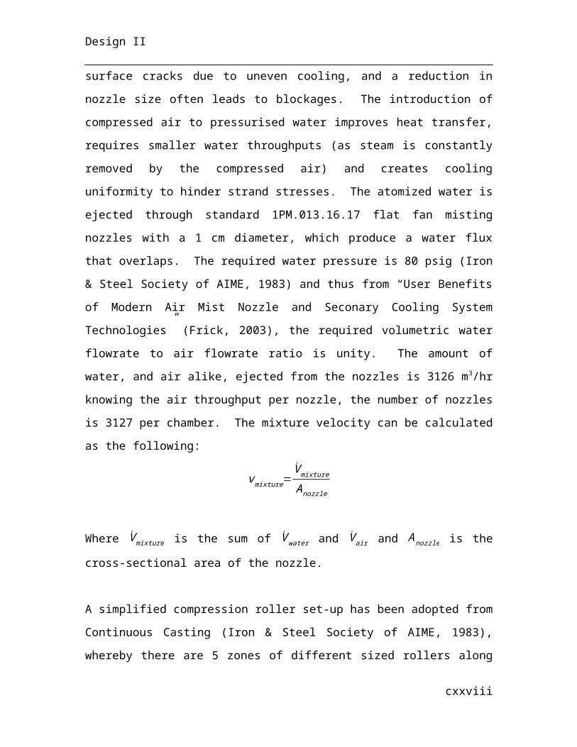
Design II
Table 22
Flux hopper sizing and specifications.
XVIII
Parameter Value Unit
Throughput 0.1275 t/hrRetention Time 7 daysVolume 7.62 m3
Agitated noDesign Ratio 1.2Design Factor 10 %
Internal VolumesCylinder Height 2.30 mCylinder Diameter 1.91 mVolume Cylinder 6.61 m3
Height of Slanted Portion 1 mTapered Diameter 0.1 mVolume of Slanted Portion 1.01 m3
Material InformationMaterial Flux(1) CaF2 Composition 75.00 %(2) SiO2 Composition 3.00 %(3) Al2O3 Composition 1.00 %(4) S Composition 1.00 %(5) CaCO3 Composition 21.00 %Density 3092.64 kg/m3
Phase PowderPressure 1 barTemperature 25 °COff-Gas Produced noDensity of CS 7850 kg/m3
Weight of CS 6.70 tMaterials of Construction
Material Carbon SteelThickness 20 mm
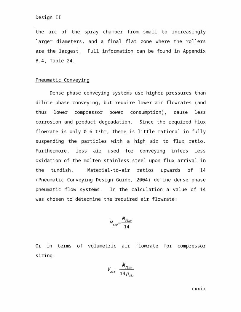
Design II
Table 23
Oscillating water-cooled mould sizing and specifications.
XIX
Parameter Value Unit
Agitated noThroughput 0.0638 t/hrRetention Time 60 minutesVolume 22675 cm3
Ratio 1.2Design Factor 10 %Discharge Valve Rotary
Internal VolumesCylinder Height 33.06 cmCylinder Diameter 27.55 cmVolume Cylinder 19705.09 cm3
Height of Slanted Portion 10 cmTapered Diameter 10 cmVolume of Slanted Portion 2969.91 cm3
Material InformationMaterial Flux(1) CaF2 Composition 75.00 %(2) SiO2 Composition 3.00 %(3) Al2O3 Composition 1.00 %(4) S Composition 1.00 %(5) CaCO3 Composition 21.00 %Density 3092.64 kg/m3
Phase PowderPressure 1 barTemperature 25 °COff-Gas Produced noDensity of CS 7850 kg/m3
Weight of CS 6.70 tMaterials of Construction
Material Carbon SteelThickness 20 mm
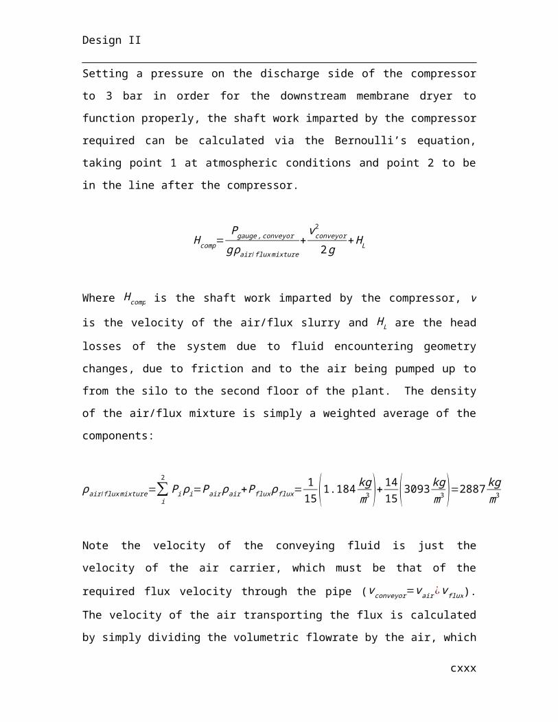
Design II
Table #24
Spray Chamber sizing and specifications.
XX
Parameter Value Unit
Mould
InteriorWater
ChamberVolumetric Throughput 43329 1173.16 m3/hrMass Throughput 118.71 117.32 t/hrRetention Time 607 1.41 secondsLength 10.00 10.00 mAgitated no noIndustry Standard Design Overcapacity - 81 %
Internal VolumesLength 10.00 10.00 mWidth 1.00 0.02 (x2) mHeight 0.25 0.02 (x2) mInternal Wall Thickness 0.04 m
Material Information
MaterialStainless
Steel Water
Average Density 7089 1000 kg/m3
Phase liquid/solid liquidAverage Pressure 52.68 1.2 bar
Temperature1800 ->
115830 -> 38.5 °C
Off-Gas Produced No NoFlow Direction Downwards UpwardsPhase PowderPressure 1 barTemperature 25 °COff-Gas Produced noDensity of CS 7850 kg/m3
Weight of CS 6.70 tMaterials of Construction
Materials CuB-HComposition Cu 99.9 %Tensile Strength 245.09 MPaProof Strength at 0.2% Elongation (MPa) 196.08 MPa
Hardness 80 HB
Design II
XXI
Parameter Value Unit
-
Water Throughput 3126.33 m3/hrWater Throughput 3126.33 t/hr
Nozzle Type
1PM.013.16.17 Flat Fan Misting
NozzleNozzle Diameter 0.005 mOverlapping Spray Area YesWater Throughput Per Nozzle 1 t/hrAir Throughput Per Nozzle 0.01124705 t/hrNumber of Nozzles 3126.325536Mixture Velocity 28.29421211 m/sIndustry Standard Design Factor 81 %
Arced Portion Zone ParametersZone 1 Zone 2 Zone 3 Zone 4 Unit
Percentage of Arc 10 10 60 20 %Length of Arc 1.92 1.92 11.50 19.36 mNozzle Spray Area Per Side 1.92 1.92 11.50 19.36 m2
Distance from Strand 17.8 17.8 58.4 58.4Rollers Diameter 220 290 350 425Number of Rollers Per Side 7 5 25 7
Straight Portion Zone ParametersZone 5 Unit
-
Percentage of Straight Portion 100 %
Length 4.00 mNozzle Spray Area Per Side 4.00 m2
Distance from Strand 58.4 cmRollers Diameter 700 mmNumber of Rollers Per Side 4
Material Information
MaterialWater / Air
Mixture
-Water Density 1000 kg/m3
Air Density 1.1839 kg/m3
Pressure (Gauge) 5.516 psigTemperature 30 °CPhase Liquid / Vapor
Design II
Table #25
Pneumatic conveyor air compressor sizing and specifications.
Table #26
Membrane air dryer specifications.
Table #27
Pneumatic conveyor blow tank sizing and specifications.
XXII
Parameter Value Unit
Air Throughput 0.003155 m3/hrPumping Height Required 30 mShaft Work Imparted 40.59 mCompressor Type Rotary-ScrewPower Required 0.1149 kW
Material InformationMaterial Cleaned AirDensity 1.1839 kg/m3
Molecular Weight 28.97 kg/kmolDischarge Temperature 361.36 °CDischarge Pressure (Gauge) 3 barPhase Vapour
Parameter Value Unit
Air Throughput 0.0032 m3/hrInlet Pressure 3 barDewpoint Suppression to -40 °C
Material InformationMaterial Ambient AirDensity 1.1839 kg/m3
Molecular Weight 28.97 kg/kmolPhase Vapor
Design II
Table #28
Air compressor for spray chamber mist sizing and specifications.
XXIII
Parameter Value Unit
Air Throughput 0.001578 m3/hrFlux Throughput 0.06 t/hrType Bottom DischargeRetention Time 30 minVolume 0.001132 m3
Agitated noDesign Ratio 1.2Design Factor 10 %
Material Information(1) Material Flux(1) CaF2 Composition 75.00 %(2) SiO2 Composition 3.00 %(3) Al2O3 Composition 1.00 %(4) S Composition 1.00 %(5) CaCO3 Composition 21.00 %Density 3092.64 kg/m3
Phase powder(2) Material Clean AirDensity 1.18 kg/m3
Phase Vapour(3) Material SlurryCoposition Flux 0.93 % (mass)Composition Air 0.07 % (mass)Phase vapor/solidPressure (Gauge) 0.2 barTemperature 47.42 °CDensity 2886.54 kg/m3
Design II
Table #29
Process water pump sizing and specifications.
Parameter Value Unit
Water Throughput 3126.33 m3/hrHead Losses Misting 15 mShaft Work Imparted 55.80 mPump Type CentrifugalNumber of Stages MulitpleImpeller Type ClosedPower 475.36 kW
Material InformationMaterial Process WaterDensity 1000 kg/m3
Pressure 1.2 barDischarge Temperature 30 °CDischarge Pressure 6.67 barPhase Liquid
XXIV
Parameter Value Unit
Air Throughput 3126.33 m3/hrHead Losses Misting 15 mShaft Work Imparted 55.80 mCompressor Type Axial-FlowPower Required 67.99 kW
Material InformationMaterial AirDensity 1.1839 kg/m3
Molecular Weight 28.97 kg/kmolPressure 1.0133 barDischarge Pressure 1.0140 barDischarge Temperature 25.16 °CPhase Vapor
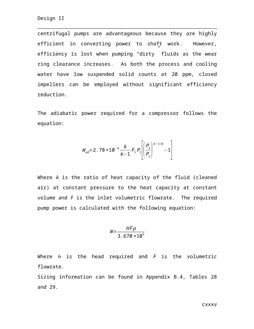
Design II
Table #30
Cooling water pump sizing and specifications.
Table #31
Power-driven roller sizing and specifications.
XXV
Parameter Value Unit
Throughput 1173.16 m3/hrHead Losses 20 mShaft Work Imparted 24.0898749 mPump Type CentrifugalNumber of Stages MultipleImpeller Type ClosedPower 77.01 kW
Material InformationMaterial Cooling WaterDensity 1000 kg/m3
Discharge Temperature 30 °CFeed Tank Pressure 1.5 barDischarge Pressure 3.86 barPhase Liquid
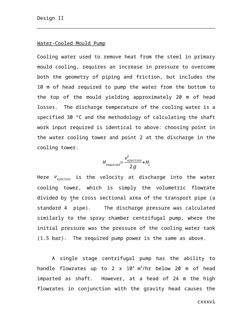
Design II
Table #32
Slab collection rack sizing and specifications.
XXVI
Parameter Value Unit
Stainless Steel Throughput 118.71 t/hrSlab Speed 0.01649 m/sLength of Powered Roll Section 20 mNumber of Rollers 58Powered Individually
Material Information
MaterialStainless Steel
SlabsDensity 6799 kg/m3
Temperature 400.00 °CPhase Solid
Materials of Construction(1) Steel Frame(2) Steel RollersDiameter 0.40 mWidth 0.25 mRoll Speed 100 s-1
Power Required 100 kWSpacing Between Rollers 0.30 m
Parameter Value Unit
Slab Throughput 5.94 hr-1
Retention Time 4.21 hrPowered No
Material Information
MaterialStainless Steel
SlabsDensity 8000 kg/m3
Inlet Temperature 400.00 °COutlet Temperature 90.00 °CWidth 10.00 mHeight 1.00 mPhase Solid
Materials of Construction(1) Steel Frame(2) Steel RollersDiameter 0.4 mLength 10.00 mWidth 25.01 mSpacing Between Rollers 0.3 m
Design II
Table #33
Air blower sizing and specifications.
Table #34
Slab-hoisting crane sizing and specifications.
XXVII
Parameter Value Unit
Air Throughput 5400 m3/hrHead Losses Misting 1 mShaft Work Imparted 170.11 mBlower Type CentrifugalBlade Type RadialRequired Power 200.60 kW
Material InformationMaterial AirDensity 1.1839 kg/m3
Molecular Weight 28.97 kg/kmolPressure 1.01325 barDischarge Temperature 25.56 °CDischarge Pressure 1.016 barPhase Vapor
Parameter Value Unit
Number of Slabs Per Hoist 3Total Weight 60 tRatio of Total Weight to Design Weight 85 %Design Weight 70.59 tPowered Electrically
Material Information
MaterialStainless Steel
SlabsDensity 8000 kg/m3
Temperature 30.00 °CLength 10.00 mWidth 1.00 mHeight 0.25 mPhase Solid
Design SpecificationsSpacing Between Wheels 4.9 mWheels per Rack 2Vertical Clearance 18 mLength 25 mWidth 3 mHeight 1 m
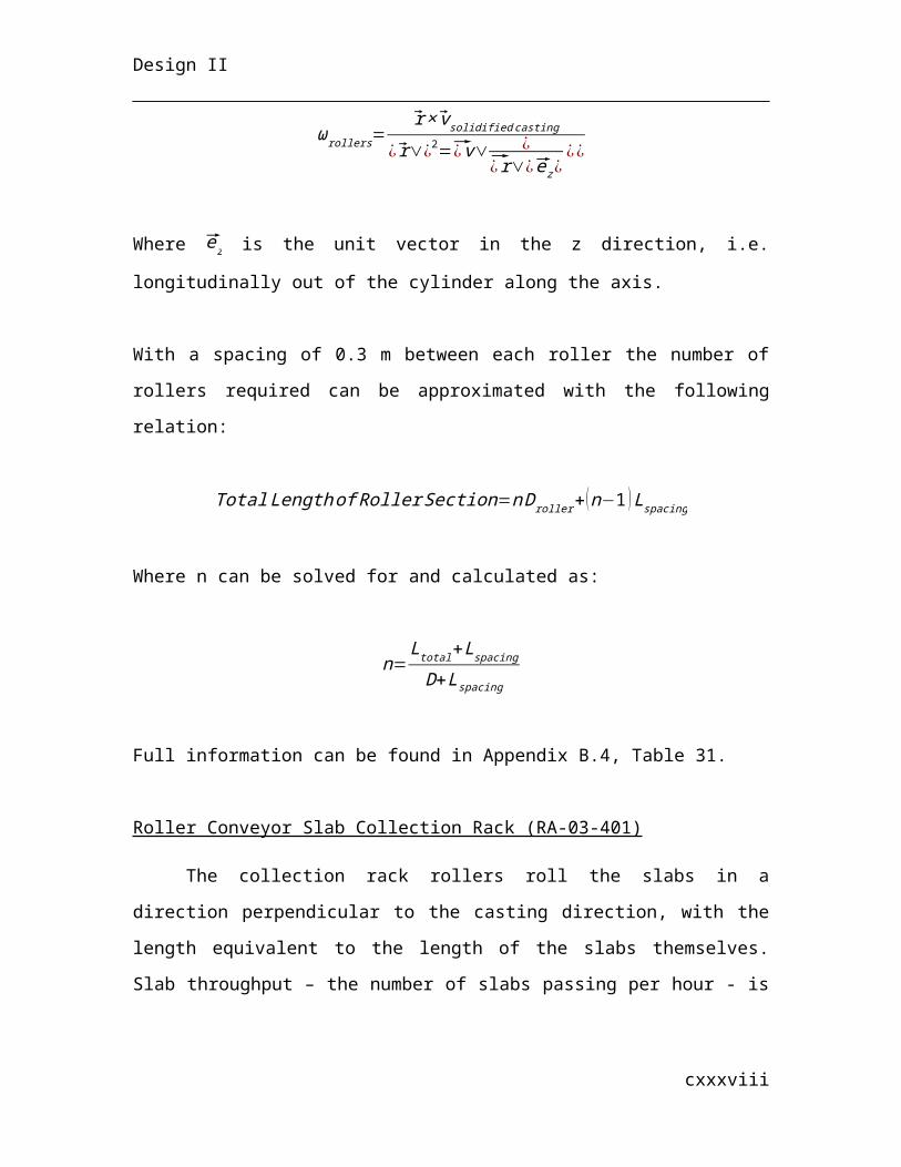
Design II
Appendix C – Capex & Opex
C.1 Capex
Costs of individual pieces of equipment were collected from different sources and used as
references to extrapolate current prices. Two main references were used to find cost
estimates are the following:
(1) Capcosts (Capcosts 1998), a handbook for costing CAPEX purchases, which depends
on the particular capacity of the equipment being sized. The equation for costing is
as follows:
Cost (US 1998 $ )=a X b
Where a and b are empirical factors and the capacity unit and calculation X are all
dependant on the piece of equipment. The following table outlines the criteria for each
XXVIII
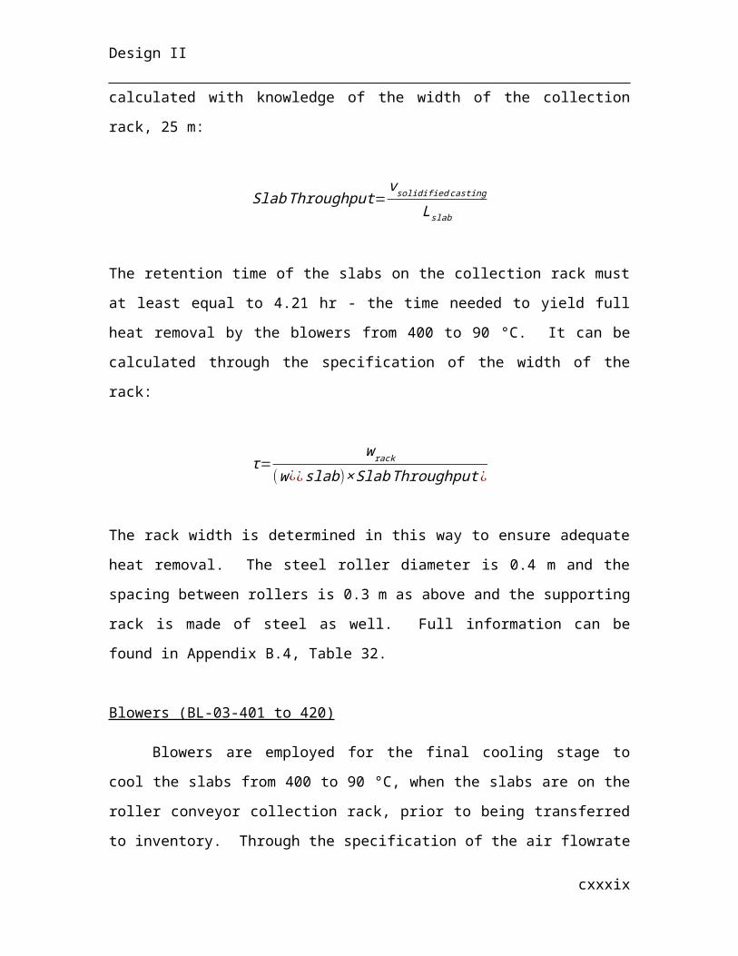
Design II
equipment sized with Capcosts.
Table 35
Equipment Capacity DescriptionCapacity
Unita b
Silo Volume capacity ft3 354 0.5372
Pneumatic Conveyor Diameter of pipe squared times length (carbon steel) ft3 31850 0.1506
Hopper Volume capacity ft3 392.8 0.46312-Stage Centrifugal Pump Volumetric flowrate capacity US GPM 5288 0.2474Axial-Flow Compressor Volumetric flowrate capacity ft3/min 4.818 0.9998Radial Centrifugal Blower Volumetric flowrate capacity ft3/min 1257 0.1636DRI, Lime and Steel Scrap Bins Bin capacity ft3 392.8 0.4631
Belt Conveyor for Lime Belt width squared multiplied by belt length ft3 1875 0.5225
Overhead Crane Lift capacity tonnes 240100 0.1504Rectangular Suspended Magnet
Product of belt width in feet times the suspension height in cubic inches ft x in3 251.6 0.4959
Lime Silos Silo capacity ft3 392.8 0.4631Air compressor; Stationay screw Volumetric flowrate cfm 384.4 0.8062
(2) A CAPEX costing example of a plant built in 1994, provided by the client.
If the capacity required was over that of the reference given, the price has been
approximated by the following equation:
Cost=Costreference [ capacitycapacityreference ]
n
Where n is the scaling up factor exponent, which varies for different pieces of equipment.
The following table outlines the exponents used for scaling up.
Table #36
XXIX
Design II
Type of Equipment Scaling Exponent nPump 0.33
If the equipment was scaled up and not present in the above table, a estimated scaling
exponent of 0.6 was assumed as is industry standard.
To bring cost to present day values, Marshall & Swift (M&S) indexes were used to take
into account inflation in prices. The following table lists the index values used at
different years to bring prices to 2014. The 2014 M&S index was extrapolated from the
second graph of page 304 of the Capcost document.
Table #37
Year Marshall & Swift Index1994 993.41998 1061.92014 1494.5
To correct costs to present day inflation values, the capital cost is multiplied by the ratio
of the current index to the year the price was obtained (the basis year). The following
equation highlights this:
Price2014=Pricebase( M ∧S index 2014
M∧S indexbase)
To account for substantial installation costs, a factor is always added to the purchase
price to more accurately estimate the price of capital expenditures.
The following table outlines the factor applied to the procurement cost used when
estimating the price of installation. These factors vary between different pieces of
equipment. The total CAPEX cost of each piece of equipment, therefore, is the cost of
procurement plus that of installation.
Table #38
XXX
Design II
Equipment Installation FactorHopper 0.254
Conveyor 0.761Continuous Caster 0.5
Pump 0.549Compressor 0.477
Blower 0.346Bins/Silos 0.254
Fan 0.392Reciprocating Pump 2.45
Overhead Crane 0.624
For capital budgeting, total plant costs are typically calculated as percentages of
equipment cost. Table XX lists these percentages and their respective weighted costs.
Building structural costs including foundation, structural steel, envelope, roof and
internal lighting are estimated to be $100/m3. With a plant volume of 211,440 m3, the
total cost is simply the product of the cost per cubic meter times the volume of the plant
($ 21,144,000).
Building costs consist of the following three sub-items:
(1) Cost of material ($100 / m3) multiplied by the total volume of the plant
(2) Cost of the crane support beam
There are a total of two overhead cranes in the plant, CN-03-201 and CN-03-202.
First to be sized and priced are the beams and supports. The cranes are designed to hold
15% more than the maximum tonnage which it will be carrying, which is 225 tonnes.
Hence they both have a design capacity of 265 tonnes. For the larger crane (CN-03-202),
a beam which is 94.5 m in length, 3.5 m in width and 2.5 m in depth with a porosity
factor of 0.75 is needed to support this weight. The porosity factor indicates how much of
the volume ascertained from the dimensions above is not filled by steel but presumably
air. The corresponding volume of such a beam is 207 cubic meters of stainless steel, or
1613 tonnes if density of steel is taken to be 7,800 kg/cubic meter. The second crane
XXXI
Design II
(CN-03-201) requires a beam 44.1 m in length, 3 m in width and 2 m in depth also with a
porosity factor of 0.75. This gives a volume of 66.15 cubic meters of steel or 516 tonnes.
A total of twenty structural supports are needed to support the beams. These
supports are larger than the typical structural supports used to erect the building. Each
support is 2 m in width, 3 m in depth and 22 m in height. This gives a volume of 33 cubic
meters of stainless steel per support and a weight of 257 tonnes each.
To connect the supports to the main beams, twenty support beams are required.
Each beam connects a support to the main beam. The support beams are also stainless
steel and 1 m in width, 1 m in depth and 3.15 in length. The volume of each beam is
therefore 3.15 cubic meters, or 24.6 tonnes.
The price of these beams and supports is determined from the combined weight of
steel. The main beams are $6,449,625.00 for CN-03-202 and $2,063,880.00 for CN-03-
201. The total price for crane supports is $20,592,000 and the total price for support
beams is $39,312,000.00. These values are obtained using a steel fabrication price of
$7,000 per tonne.
C.2 - OPEX
The operating expenses highlight the cost of raw materials, utilities, labour wages,
supplies and waste disposal for plant operation per annum. The quantity of units is
tabulated for the entire plant and multiplied by the cost per unit.
For example the cost of steel scrap used in the EAF is as follows:
Cost scrap=costunit
× no .unitsannum
=(200 $unit )(150,000 units
an )=$30,000,000
Labour wage costs were averaged over the wages of the administrative staff, the
operators and the maintenance workers (including benefits) to be $ 100,000 per annum
per unit. Since operation occurs 24 hours a day, 7 days a week, there are 4 shifts required
XXXII
Design II
for operation and maintenance (3 shifts on per day and one off). Therefore, if there are
an arbitrary 10 operators required at any given time, 40 must be employed in total. Only
administrative staff shift is required.
Net Present Value of Investment
All following return on investment calculations were performed under the following
assumptions:
The cost of depreciation rate of the fixed assets in the plant is 10% and the asset
pool follows declining balance depreciation
The corporate tax rate is 40%
The investment is 100% equity and therefore a high cost of capital rate is utilised
(10%)
A non-integrated taxation method where depreciation losses are not allowed was
selected, which yields the lowest NPV and IRR as the most conservative possible
estimate
The total capital investment of the plant is split equally over the first three years of
pre-production
The total project lifespan is 20 years
Annual revenue was calculated knowing the price of stainless steel sold to the market and
with knowledge of the average output volume of the plant per year, in addition to the slag
sold from Group 3 and the chips sold from Group 1.
Annual Revenue=(2million tannum )(2,650 $
t−20 $
t )+(251,135 tannum )(10 $
t )+(12,397 tannum)(92.19 $
t )=$ 5.26 billion
Where the stainless steel sells on the market for 2,650 $/t, but the shipping costs are
20$/t.
The annual expenses are simply the summation of the three groups annual OPEX and the
annual profits can be calculated with the following equation:
Annual Profit=Revenue−AnnualOPEX
XXXIII
Design II
Depreciation was calculated using a declining balance method, at 10% per annum. The
general formula for calculating the deductible depreciation at a given ith year is:
Deductable Depreciation=D (Investment−∑i
DD i)
Where D is the depreciation rate and DDi is depreciation cost of the ith year.
For example in the second year, the depreciation deduction from taxable income was the
following:
DD=0.1 ($ 2,131,121,504− ($213,112,150+$ 191,800,935 ) )=$ 172,620,842
The taxable profits are therefore the annual profits subtracted by the depreciation
deduction allowed by the government. The general equation for the net cash flow (NCF)
can be given by the following:
NCF=( Revenue−OPEX−Depreciation ) (1−corperate tax )+Depreciation
This equation simply removes the deductible depreciation from taxation and re-adds the
depreciation after the tax factor has been employed.
Converting the future values of projected earnings to its present day monetary value with
the discount rate:
PV = FV(1+i)n
Where PV is present value of money, FV is the future value at the n th year and i is the
discount rate.
For example, in the second year:
PV =−$ 710,373,835(1.15)2 =−$ 587,085,814
The sum of the cash flows at present value give yearly cumulative cash flow and at the
end of the 20 year project lifespan, the value of the cumulative cash flow is the NPV of
the project. Note in the last year the salvage value of all assets is included in the
cumulative cash flow via the following equation:
XXXIV
Design II
SV=(1−D ×TC
D+ i )(1+i)20
Where TC is the corporate tax factor at 40%.
See Table 39 for all figures.
Table 39
XXXV
Year Annual Revenue
Annual Expenses
Annual Profits Investment Depreciation Deduction
Taxable Profits
Taxes
0 $0 $0 $0 $710,373,835 $213,112,150 $01 $0 $0 $0 $710,373,835 $191,800,935 $02 $0 $0 $0 $710,373,835 $172,620,842 $03 $5,263,654,229 $4,180,913,704 $1,082,740,525 - $155,358,758 $927,381,768 $370,952,7074 $5,263,654,229 $4,180,913,704 $1,082,740,525 - $139,822,882 $942,917,644 $377,167,0575 $5,263,654,229 $4,180,913,704 $1,082,740,525 - $125,840,594 $956,899,932 $382,759,9736 $5,263,654,229 $4,180,913,704 $1,082,740,525 - $113,256,534 $969,483,991 $387,793,5967 $5,263,654,229 $4,180,913,704 $1,082,740,525 - $101,930,881 $980,809,645 $392,323,8588 $5,263,654,229 $4,180,913,704 $1,082,740,525 - $91,737,793 $991,002,733 $396,401,0939 $5,263,654,229 $4,180,913,704 $1,082,740,525 - $82,564,014 $1,000,176,512 $400,070,605
10 $5,263,654,229 $4,180,913,704 $1,082,740,525 - $74,307,612 $1,008,432,913 $403,373,16511 $5,263,654,229 $4,180,913,704 $1,082,740,525 - $66,876,851 $1,015,863,675 $406,345,47012 $5,263,654,229 $4,180,913,704 $1,082,740,525 - $60,189,166 $1,022,551,360 $409,020,54413 $5,263,654,229 $4,180,913,704 $1,082,740,525 - $54,170,249 $1,028,570,276 $411,428,11014 $5,263,654,229 $4,180,913,704 $1,082,740,525 - $48,753,224 $1,033,987,301 $413,594,92015 $5,263,654,229 $4,180,913,704 $1,082,740,525 - $43,877,902 $1,038,862,624 $415,545,04916 $5,263,654,229 $4,180,913,704 $1,082,740,525 - $39,490,112 $1,043,250,414 $417,300,16617 $5,263,654,229 $4,180,913,704 $1,082,740,525 - $35,541,101 $1,047,199,425 $418,879,77018 $5,263,654,229 $4,180,913,704 $1,082,740,525 - $31,986,990 $1,050,753,535 $420,301,41419 $5,263,654,229 $4,180,913,704 $1,082,740,525 - $28,788,291 $1,053,952,234 $421,580,89420 $5,263,654,229 $4,180,913,704 $1,082,740,525 - $25,909,462 $1,056,831,063 $422,732,425
Design II
Internal Rate of Return
The internal rate of return is calculated by using solver to calculate the value at which
NPV is equivalent to zero by altering the cost of capital (or the interest rate). Table 40
highlights this calculation.
Table 40
36
Year Annual Revenue
Annual Expenses
Annual Profits Investment Depreciation Deduction
Taxable Profits
0 $0 $0 $0 $710,373,835 $213,112,150 $01 $0 $0 $0 $710,373,835 $191,800,935 $02 $0 $0 $0 $710,373,835 $172,620,842 $03 $5,263,654,229 $4,180,913,704 $1,082,740,525 - $155,358,758 $927,381,768 $370,952,7074 $5,263,654,229 $4,180,913,704 $1,082,740,525 - $139,822,882 $942,917,644 $377,167,0575 $5,263,654,229 $4,180,913,704 $1,082,740,525 - $125,840,594 $956,899,932 $382,759,9736 $5,263,654,229 $4,180,913,704 $1,082,740,525 - $113,256,534 $969,483,991 $387,793,5967 $5,263,654,229 $4,180,913,704 $1,082,740,525 - $101,930,881 $980,809,645 $392,323,8588 $5,263,654,229 $4,180,913,704 $1,082,740,525 - $91,737,793 $991,002,733 $396,401,0939 $5,263,654,229 $4,180,913,704 $1,082,740,525 - $82,564,014 $1,000,176,512 $400,070,605
10 $5,263,654,229 $4,180,913,704 $1,082,740,525 - $74,307,612 $1,008,432,913 $403,373,16511 $5,263,654,229 $4,180,913,704 $1,082,740,525 - $66,876,851 $1,015,863,675 $406,345,47012 $5,263,654,229 $4,180,913,704 $1,082,740,525 - $60,189,166 $1,022,551,360 $409,020,54413 $5,263,654,229 $4,180,913,704 $1,082,740,525 - $54,170,249 $1,028,570,276 $411,428,11014 $5,263,654,229 $4,180,913,704 $1,082,740,525 - $48,753,224 $1,033,987,301 $413,594,92015 $5,263,654,229 $4,180,913,704 $1,082,740,525 - $43,877,902 $1,038,862,624 $415,545,04916 $5,263,654,229 $4,180,913,704 $1,082,740,525 - $39,490,112 $1,043,250,414 $417,300,16617 $5,263,654,229 $4,180,913,704 $1,082,740,525 - $35,541,101 $1,047,199,425 $418,879,77018 $5,263,654,229 $4,180,913,704 $1,082,740,525 - $31,986,990 $1,050,753,535 $420,301,41419 $5,263,654,229 $4,180,913,704 $1,082,740,525 - $28,788,291 $1,053,952,234 $421,580,89420 $5,263,654,229 $4,180,913,704 $1,082,740,525 - $25,909,462 $1,056,831,063 $422,732,425
Design II
Appendix D – Process Flow Diagrams
37
Design II
38

Design II
39
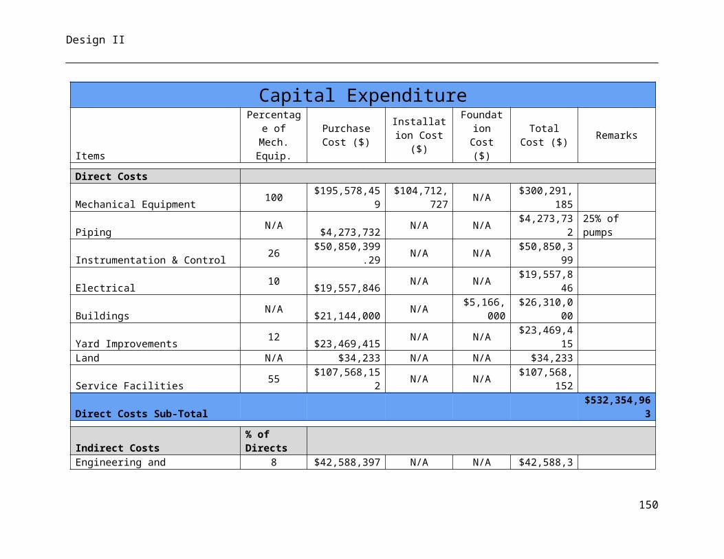
Design II
40
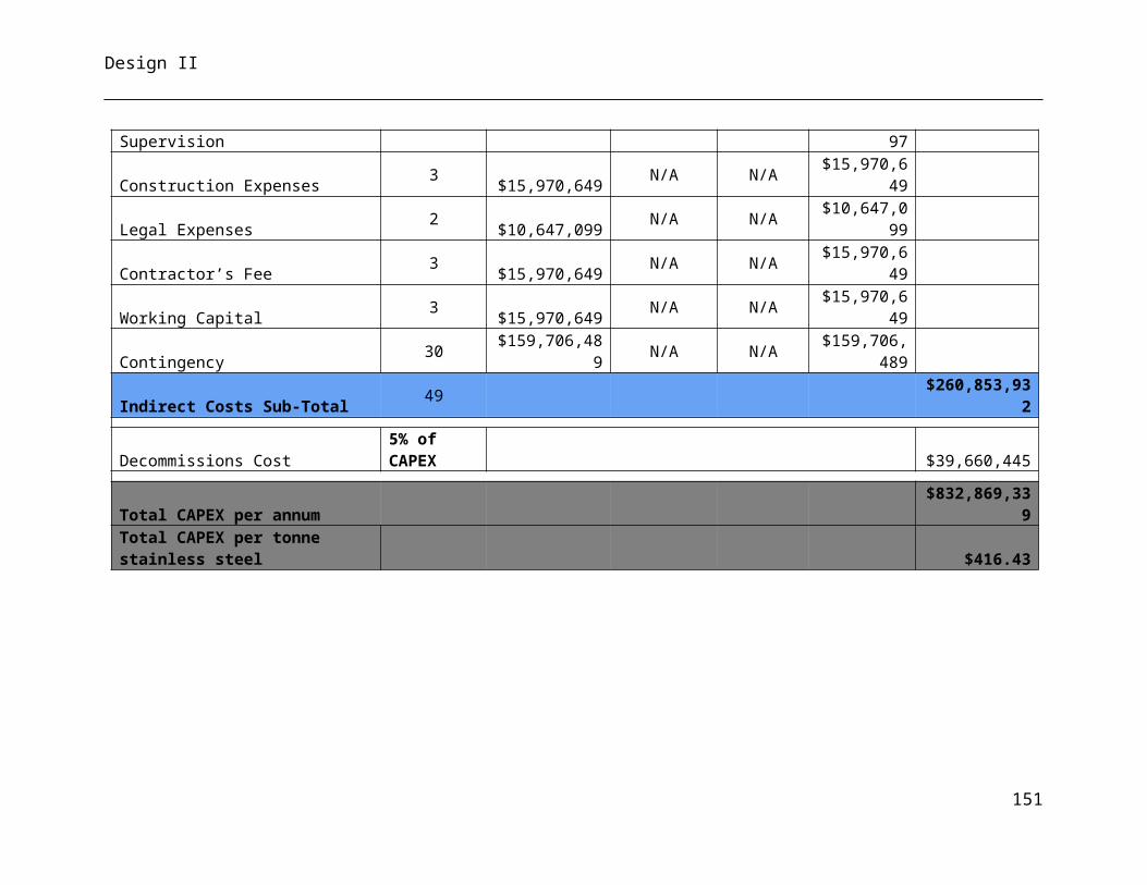
Design II
41
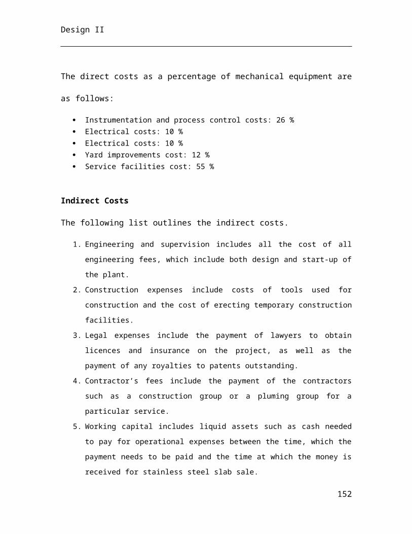
Design II
42
Design II
43
Design II
44
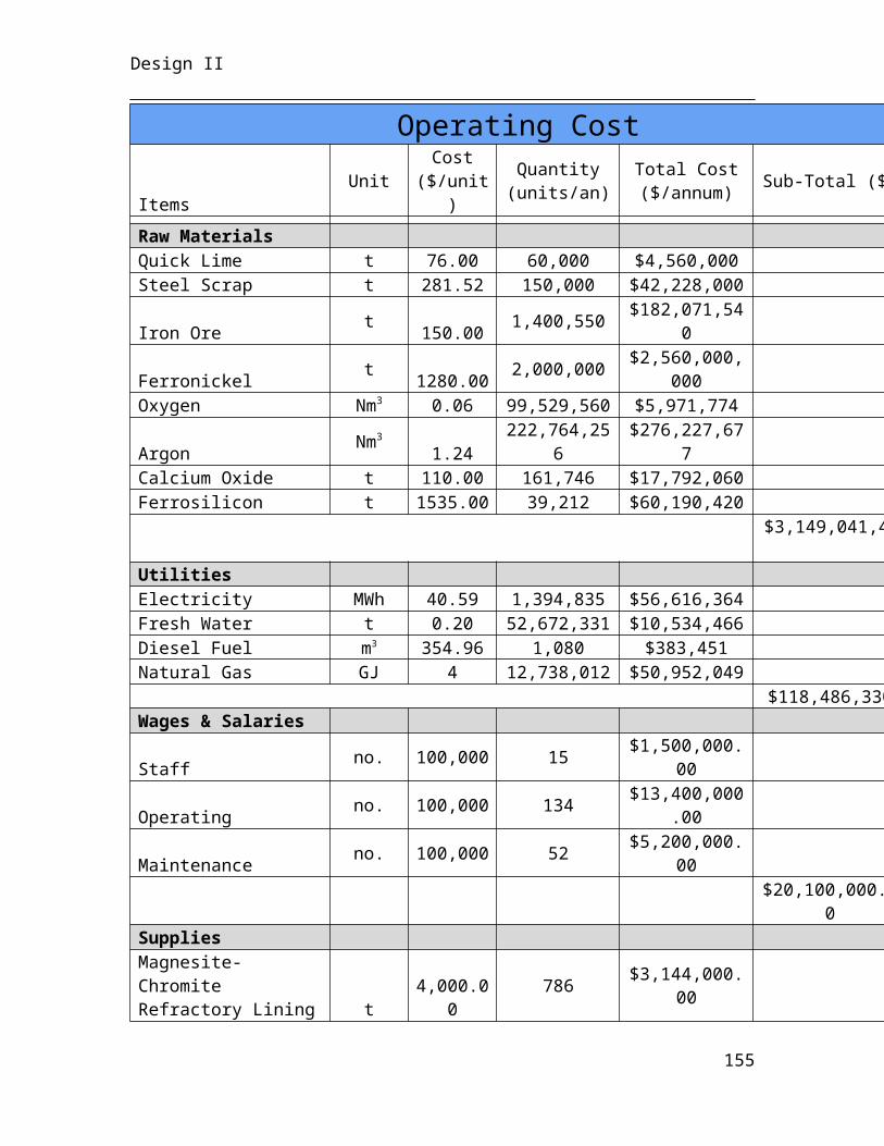
Design II
45
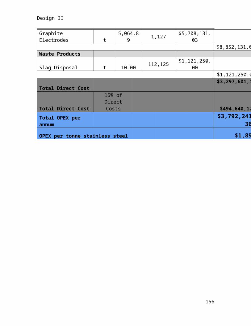
Design II
Appendix E – Process & Instrumentation Diagrams
46
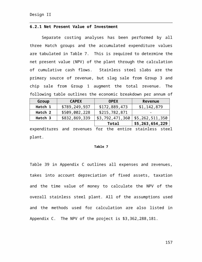
Design II
47
Design II
48
Design II
49
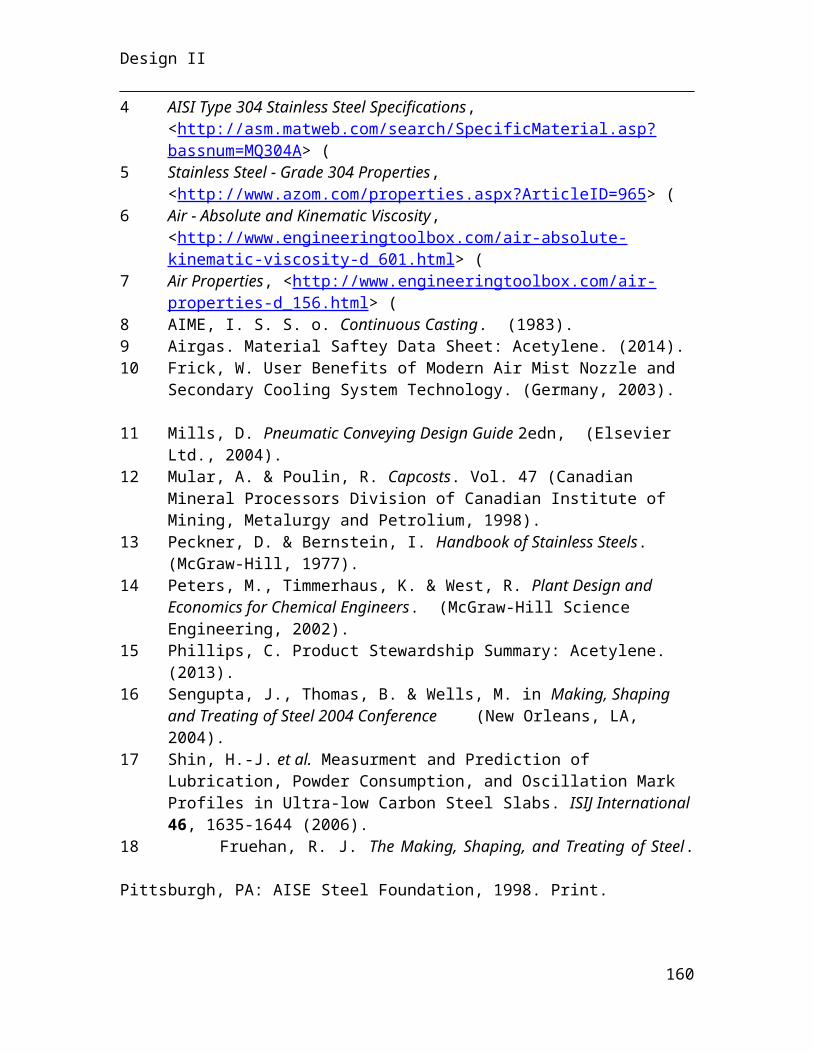
Design II
50

Design II
Appendix F – Plant Layout
51
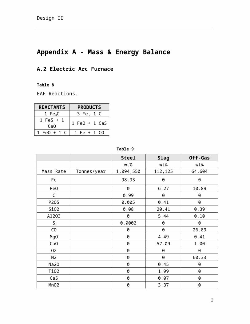
Design II
52
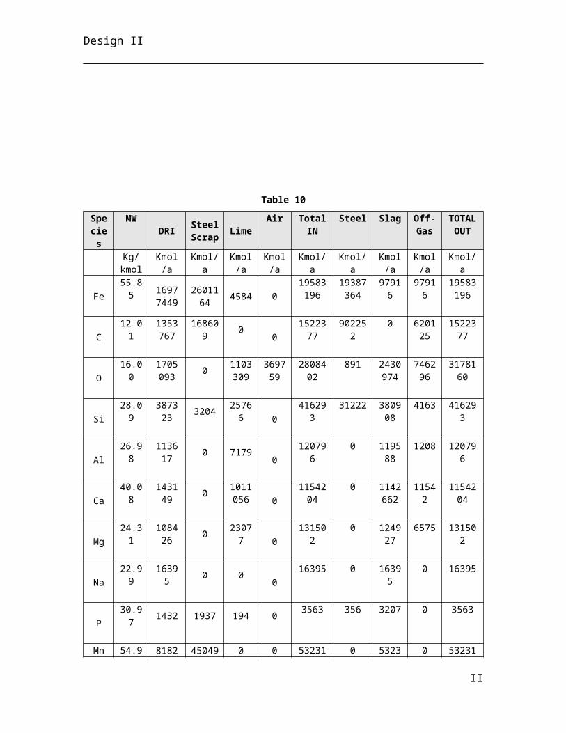
Design II
53
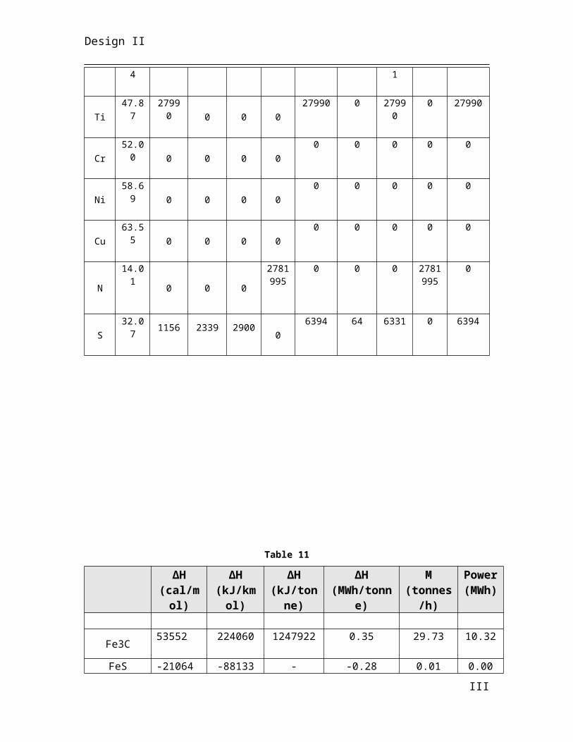
Design II
54
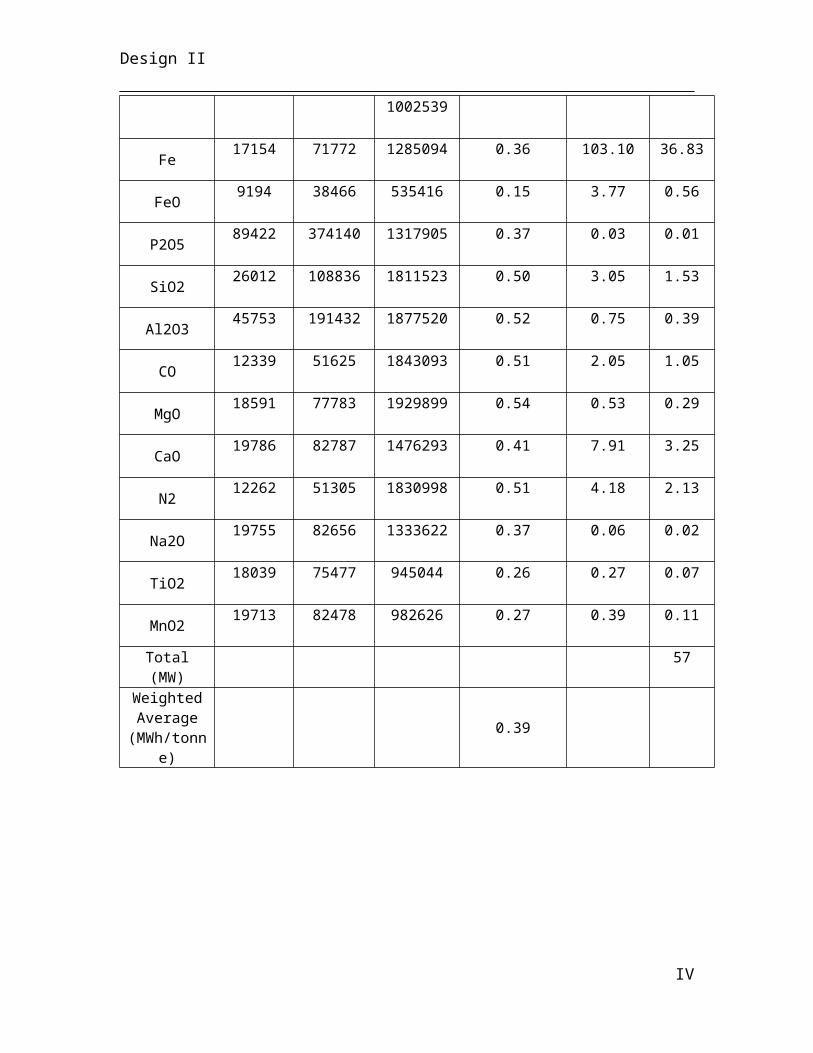
Design II
Appendix F – Equipment List
55
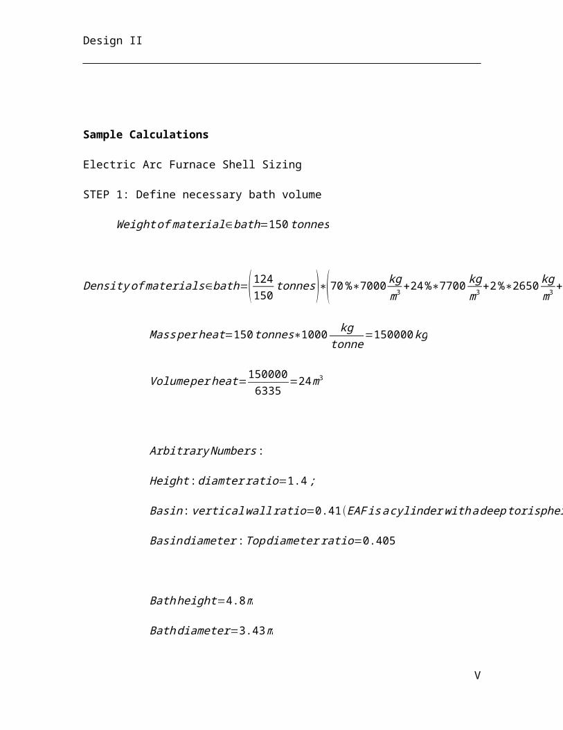
Design II
IDENTIFICATION TECHNICAL PROCUREMENT DESIGN DATA POWE
RDIAGRAMS COST Supp. Information
Item
Area Tag No. Description Equip. Type Dimensions(l x w x h)
External Material
Operating Mode
Design Capacity
Installed
(kW)
PFD No. Unit Cost($)
Remarks
Internal Material
P&ID No.
Argon Oxygen Decarburizers
AOD reactor AOD-03-301
Argon oxygen decarburizer AOD
Outer dia: 8 m; Bottom dia: 4 m;
Height: 11 m Carbon steel Intermittent 180 t/h N/A PFD-03-005 $10,062,788
2 AOD needed for 1 hour basis
Note: 1 AOD per batch
Bins/Silos/Hoppers AOD feed
prepBN-03-301(2)
Storage bin for HCFeCr
(granules)Storage bin 7 m, 2 m, 7 m SS316 Carbon
steel 6 m3 N/A PFD-03-004 $8,281 3 + 1 spare
AOD feed
prepBN-03-303
(2)Storage bin for
FeNi40 Storage bin 7 m, 2 m, 7 m Carbon steel Continuous 6 m3 N/A PFD-03-004 $7,611 3 +1 spare
AOD feed prep SI-03-301 Silo for flux Silo
Inside Dia: 7 m; Cone Dia: 20 m;
Height: 20 m Carbon steel Continuous 11 m3 N/A PFD-03-004 $18,901
AOD feed
prep HP-03-301 Hopper for flux Hopper 1 m, 4 m, 1 m Carbon steel Continuous 11 m3 N/A PFD-03-004 $10,965
AOD feed
prep BN-03-301 Receiving bin for flux
Receiving bin / Storage bin 1 m, 4 m, 1 m Carbon steel Continuous 11 m3 N/A PFD-03-004 $18,901
AOD reactor BN-03-305 (3)
Storage bin for flux, FeNi40,
HCFeCrStorage bin
Flux: 7 m, 2 m, 6 m FeNi40: 7 m, 2 m, 7 m HCFeCr: 7
m, 2 m, 7 m
Carbon steel Intermittent
Flux: 5m3
FeNi40: 6m3
HCFeCr: 6m3
N/A PFD-03-005$7,611 / $8,281 / $8,281
3 bins total
Midrex furnace HP-03-101
Charge hopper for midrex furnace
Charge hopper 6 m, 6 m, 12 m SS316 Continuous 210 t/h PFD-03-002
EAF
BN-03-201(2),
BN-03-202 (2)
Charge bin for hot DRI, lime and
steel scrapBin
Height: 5 m; Dia: 3 m;
Cone height: 1 m; Opening Dia: 1.5 m
Carbon steel Intermittent 225 t/h N/A PFD-03-003 $153,550.00 Steel thickness: 0.05 m
EAF SI-03-201(3) Lime pebble silo Silo
Height: 27 m; Dia: 7 m;
Cone height: 5 m; Opening Dia: 0.6 m
Carbon steel Batch 24000 t/a N/A PFD-03-003 $1,349,452 Shell thickness: 0.05 m
Continuous Casting SI-03-401 Flux Silo Silo Tank d-3.3m x h-2m Carbon Steel Continuous 25 t or 7
days N/A PFD-03-006 12953.89
Continuous Casting HP-03-401 Flux Hopper Hopper d-0.4m x h-0.5m Carbon Steel Continuous 0.1 t or 1
hour N/A PFD-03-006 625.18
Continuous Casting HP-03-402 Flux Hopper Hopper d-0.4m x h-0.5m Carbon Steel Continuous 0.1 t or 1
hour N/A PFD-03-006 625.18
Blowers
Reformer AB-03-101 Combustion air Air blower 0.51 m - 0.76 m Continuous 240,000 PFD-03-001
56
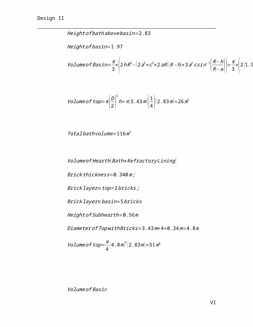
Design II
blower diameter blade wheels m3/h
Continuous Casting BL-03-401
Radial Centrifugal
BlowerBlower / / Continuous 5400 m3/h 201 PFD-03-007 8907.42
Minimum Required Head:
170 m Connection: 4" piping Blade Type: Radial
Continuous Casting BL-03-402
Radial Centrifugal
BlowerBlower / / Continuous 5400 m3/h 201 PFD-03-007 8907.42
Minimum Required Head:
170 m Connection: 4" piping Blade Type: Radial
Continuous Casting BL-03-403
Radial Centrifugal
BlowerBlower / / Continuous 5400 m3/h 201 PFD-03-007 8907.42
Minimum Required Head:
170 m Connection: 4" piping Blade Type: Radial
Continuous Casting BL-03-404
Radial Centrifugal
BlowerBlower / / Continuous 5400 m3/h 201 PFD-03-007 8907.42
Minimum Required Head:
170 m Connection: 4" piping Blade Type: Radial
Continuous Casting BL-03-405
Radial Centrifugal
BlowerBlower / / Continuous 5400 m3/h 201 PFD-03-007 8907.42
Minimum Required Head:
170 m Connection: 4" piping Blade Type: Radial
Continuous Casting BL-03-406
Radial Centrifugal
BlowerBlower / / Continuous 5400 m3/h 201 PFD-03-007 8907.42
Minimum Required Head:
170 m Connection: 4" piping Blade Type: Radial
Continuous Casting BL-03-407
Radial Centrifugal
BlowerBlower / / Continuous 5400 m3/h 201 PFD-03-007 8907.42
Minimum Required Head:
170 m Connection: 4" piping Blade Type: Radial
Continuous Casting BL-03-408
Radial Centrifugal
BlowerBlower / / Continuous 5400 m3/h 201 PFD-03-007 8907.42
Minimum Required Head:
170 m Connection: 4" piping Blade Type: Radial
Continuous
Casting BL-03-409 Radial Centrifugal Blower / / Continuous 5400 m3/h 201 PFD-03-007 8907.42 Minimum
Required Head:
57

Design II
Blower
170 m Connection: 4" piping Blade Type: Radial
Continuous Casting BL-03-410
Radial Centrifugal
BlowerBlower / / Continuous 5400 m3/h 201 PFD-03-007 8907.42
Minimum Required Head:
170 m Connection: 4" piping Blade Type: Radial
Continuous Casting BL-03-411
Radial Centrifugal
BlowerBlower / / Continuous 5400 m3/h 201 PFD-03-007 8907.42
Minimum Required Head:
170 m Connection: 4" piping Blade Type: Radial
Continuous Casting BL-03-412
Radial Centrifugal
BlowerBlower / / Continuous 5400 m3/h 201 PFD-03-007 8907.42
Minimum Required Head:
170 m Connection: 4" piping Blade Type: Radial
Continuous Casting BL-03-413
Radial Centrifugal
BlowerBlower / / Continuous 5400 m3/h 201 PFD-03-007 8907.42
Minimum Required Head:
170 m Connection: 4" piping Blade Type: Radial
Continuous Casting BL-03-414
Radial Centrifugal
BlowerBlower / / Continuous 5400 m3/h 201 PFD-03-007 8907.42
Minimum Required Head:
170 m Connection: 4" piping Blade Type: Radial
Continuous Casting BL-03-415
Radial Centrifugal
BlowerBlower / / Continuous 5400 m3/h 201 PFD-03-007 8907.42
Minimum Required Head:
170 m Connection: 4" piping Blade Type: Radial
Continuous Casting BL-03-416
Radial Centrifugal
BlowerBlower / / Continuous 5400 m3/h 201 PFD-03-007 8907.42
Minimum Required Head:
170 m Connection: 4" piping Blade Type: Radial
Continuous Casting BL-03-417
Radial Centrifugal
BlowerBlower / / Continuous 5400 m3/h 201 PFD-03-007 8907.42
Minimum Required Head:
170 m Connection: 4" piping Blade Type: Radial
58
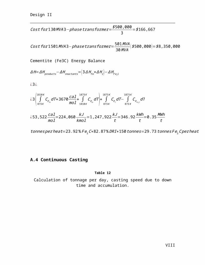
Design II
Continuous Casting BL-03-418
Radial Centrifugal
BlowerBlower / / Continuous 5400 m3/h 201 PFD-03-007 8907.42
Minimum Required Head:
170 m Connection: 4" piping Blade Type: Radial
Continuous Casting BL-03-419
Radial Centrifugal
BlowerBlower / / Continuous 5400 m3/h 201 PFD-03-007 8907.42
Minimum Required Head:
170 m Connection: 4" piping Blade Type: Radial
Continuous Casting BL-03-420
Radial Centrifugal
BlowerBlower / / Continuous 5400 m3/h 201 PFD-03-007 8907.42
Minimum Required Head:
170 m Connection: 4" piping Blade Type: Radial
Boat Transfers River Dock BT-03-101 Iron ore transfer Boat transfer Intermittent 210 t/h PFD-03-002 1 boat/week Boilers
AOD boiler B-03-101 Water boiler Boiler 5 m, 2.5 m, 2 m SS316 Continuous 24 million
BTU/hr PFD-03-001 Water is heated to 400 °C
Caster
Continuous
Casting Multiple Continuous Caster
Casting Apparatus / Carbon Steel Continuous / / PFD-03-006 $75,000,000.0
0
Continuous
Casting Multiple Continuous Caster
Casting Apparatus / Carbon Steel Continuous / / PFD-03-006 $75,000,000.0
0
Compressors
Scrubber CP-03-101 Centrifugal
compessor Air compessor 1.27 m, 0.64 m, 1.02 m SS316 Intermittent 55,000
m3/h PFD-03-001
Continuous Casting
CP-03-401 A
Rotary Screw Air Compressor
Rotary Screw Compressor / / Continuous 0.1 m3 air/h 0.2 PFD-03-006
cost under pneumatic conveyor
Minimum Required head:
41 m
Continuous Casting
CP-03-401 B
Rotary Screw Air Compressor
Rotary Screw Compressor / / Continuous 0.1 m3 air/h 0.2 PFD-03-006
cost under pneumatic conveyor
Minimum Required head:
41 m
Continuous Casting
CP-03-402 A
Axial-Flow Compressor Compressor / / Continuous 3150 m3/h 70 PFD-03-006 $18,540.25
Single Stage Minimum
Required head: 56 m
Continuous Casting
CP-03-402 B
Axial-Flow Compressor Compressor / / Continuous 3150 m3/h 70 PFD-03-006 $18,540.25
Single Stage Minimum
Required head: 56 m
Continuous Casting
CP-03-403 A
Axial-Flow Compressor Compressor / / Continuous 3150 m3/h 70 PFD-03-006 $18,540.25
Single Stage Minimum
Required head: 56 m
Continuous CP-03-403 Axial-Flow Compressor / / Continuous 3150 m3/h 70 PFD-03-006 $18,540.25 Single Stage
59
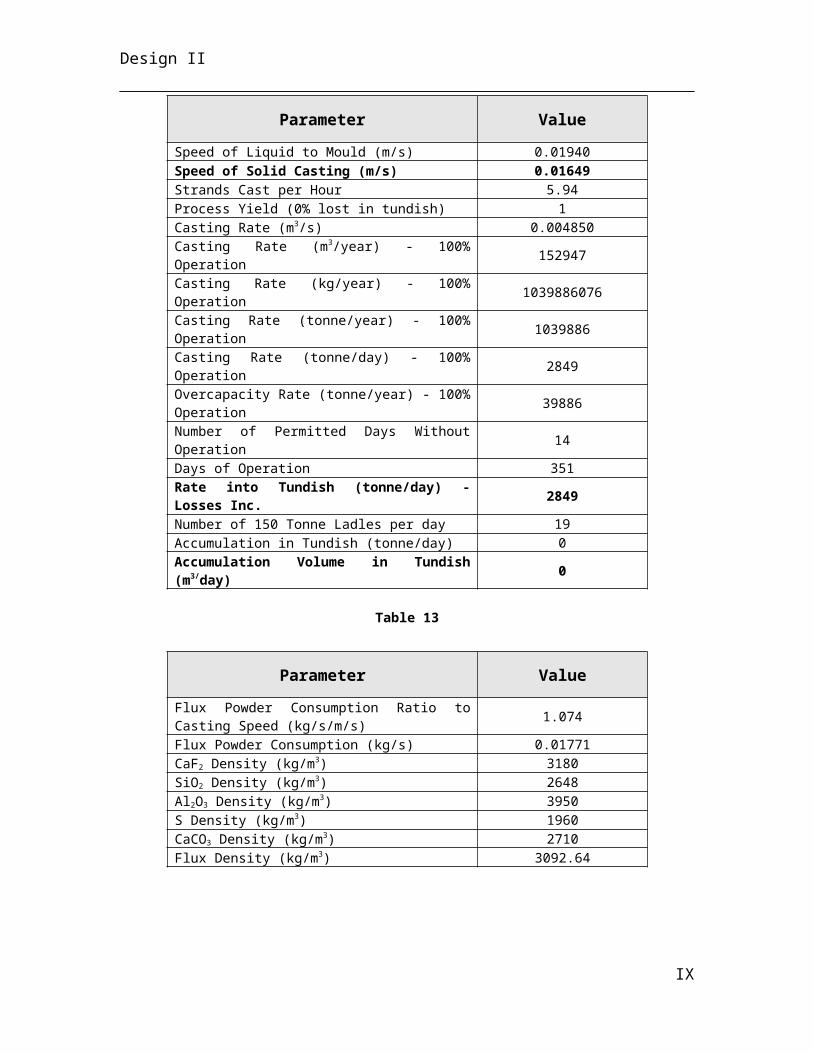
Design II
Casting B CompressorMinimum
Required head: 56 m
Conveyors
AOD feed prep CV-03-301
Conveyor belt for transporting
granulesConveyor Length: 29 m;
Width: 7 mCarbon steel/
Rubber Continuous 800-900 t/h 25 kW PFD-03-004 $1,027,547 2 needed
AOD feed prep CV-03-302
Conveyor belt for transporting
FeNi40Conveyor Length: 29 m;
Width: 9 mCarbon steel/
Rubber Continuous 800-900 t/h 25 kW PFD-03-004 $1,027,547 2 needed
AOD feed prep CV-03-303 Conveyor belt for
transporting flux Conveyor Length: 29 m; Width: 2 m
Carbon steel / Rubber Continuous 800-900 t/h 25 kW PFD-03-004 $1,027,547 2 needed
AOD reactor CV-03-304
Conveyor belt for transporting
powdersConveyor Length: 29 m;
Width: 3 mCarbon steel /
Rubber Continuous 800-900 t/h 25 kW PFD-03-005 $1,027,547.00
EAF CV-03-201 Lime pebble
conveyor Conveyor Length: 40 m; Width: 2 m
Carbon steel/ Rubber Continuous 17 t/h 25 kW PFD-03-003 $165,000.00
River Dock CV-03-101 Iron ore transfer Conveyor Continuous 210 t/h PFD-03-002
Midrex furnace CV-03-102 Hot charge of
DRI to EAF Conveyor 100 m, 2 m, 2 m Intermittent 150 t/h PFD-03-002
Continuous
Casting Multiple Flux Pneumatic Conveyor
Pneumatic Conveyor / Carbon Steel Continuous .01 m3 air/h
0.5 t/h / PFD-03-006 $101,267.17
Continuous
Casting Multiple Flux Pneumatic Conveyor
Pneumatic Conveyor / Carbon Steel Continuous .01 m3 air/h
0.5 t/h / PFD-03-006 $101,267.17
Cranes
AOD feed prep CN-03-301 Crane for
handling Ladles Crane Clear span: 30m Length: 42m Height: 9m
Carbon Steel Intermittent 350 t/h 16.6kW PFD-03-004 $2,011,316
EAF CN-03-202
Suspended crane for handling EAF input and output
CraneClear span: 12 m; Length: 94.5 m;
Height: 9 mCarbon Steel Intermittent 530 t/h 16.6 kW PFD-03-003 $542,201
EAF CN-03-201
Suspeded Crane for weighing and
transport feed bins
CraneClear span: 12 m; Length: 44.1 m;
Height: 9 mCarbon Steel Intermittent 530 t/h 16.6 kW PFD-03-003 $542,201
EAF CN-03-204
Suspended magnet with
induced current for picking up steel scrap
Crane 3 m, 3 m, 1 m Carrbon steel Intermittent 45 t/h 16.6 kW PFD-03-003 $37,841
Continuous Casting CN-03-401 Hoisting Crane Crane 25 m x 5 m x 1 m / Intermittent
Lift Capacity:
75 t16.6 PFD-03-007 $800,559.09
2 Wheels per rack with a 4.9 m
space Vertical
Clearance: 18 m Electrically Powered
60

Design II
Cylinders
Continuous Casting BT-03-401
Compressed Acetylene Cylinder
Manifolded in 2 Banks
Gas Cylinder / High Pressure Steel Intermittent 125 ft3 / PFD-03-006
cost under continuous
casting
Manifolded in Bank 1
Continuous Casting BT-03-402
Compressed Acetylene Cylinder
Manifolded in 2 Banks
Gas Cylinder / High Pressure Steel Intermittent 125 ft3 / PFD-03-006
cost under continuous
casting
Manifolded in Bank 1
Continuous Casting BT-03-403
Compressed Acetylene Cylinder
Manifolded in 2 Banks
Gas Cylinder / High Pressure Steel Intermittent 125 ft3 / PFD-03-006
cost under continuous
casting
Manifolded in Bank 1
Continuous Casting BT-03-404
Compressed Acetylene Cylinder
Manifolded in 2 Banks
Gas Cylinder / High Pressure Steel Intermittent 125 ft3 / PFD-03-006
cost under continuous
casting
Manifolded in Bank 1
Continuous Casting BT-03-405
Compressed Acetylene Cylinder
Manifolded in 2 Banks
Gas Cylinder / High Pressure Steel Intermittent 125 ft3 / PFD-03-006
cost under continuous
casting
Manifolded in Bank 1
Continuous Casting BT-03-406
Compressed Acetylene Cylinder
Manifolded in 2 Banks
Gas Cylinder / High Pressure Steel Intermittent 125 ft3 / PFD-03-006
cost under continuous
casting
Manifolded in Bank 1
Continuous Casting BT-03-407
Compressed Acetylene Cylinder
Manifolded in 2 Banks
Gas Cylinder / High Pressure Steel Intermittent 125 ft3 / PFD-03-006
cost under continuous
casting
Manifolded in Bank 2
Continuous Casting BT-03-408
Compressed Acetylene Cylinder
Manifolded in 2 Banks
Gas Cylinder / High Pressure Steel Intermittent 125 ft3 / PFD-03-006
cost under continuous
casting
Manifolded in Bank 2
Continuous Casting BT-03-409
Compressed Acetylene Cylinder
Manifolded in 2 Banks
Gas Cylinder / High Pressure Steel Intermittent 125 ft3 / PFD-03-006
cost under continuous
casting
Manifolded in Bank 2
Continuous Casting
BT-03-4010
Compressed Acetylene Cylinder
Manifolded in 2 Banks
Gas Cylinder / High Pressure Steel Intermittent 125 ft3 / PFD-03-006
cost under continuous
casting
Manifolded in Bank 2
Continuous BT-03-411 Compressed Gas Cylinder / High Pressure Intermittent 125 ft3 / PFD-03-006 cost under Manifolded in
61

Design II
Casting
Acetylene Cylinder
Manifolded in 2 Banks
Steel continuous casting Bank 2
Continuous Casting BT-03-412
Compressed Acetylene Cylinder
Manifolded in 2 Banks
Gas Cylinder / High Pressure Steel Intermittent 125 ft3 / PFD-03-006
cost under continuous
casting
Manifolded in Bank 2
Dryers
Continuous Casting DR-03-401 Membrane Air
Dryer Dryer / / Continuous 0.01 m3
air/h / PFD-03-006cost under pneumatic conveyor
Inlet P = 3 bar Dewpoint
Supressed to -40 °C
Electric Arc Furnaces
EAFEAF-03-
201, EAF-03-202
Hearth, shell, cooling panels
Electric arc furnace
Height: 5.35 m; Dia: 4.8 m
Carbon steel / Magnesite-
chromite brickIntermittent 350 t/h N/A PFD-03-003 $171,046.69
EAF
RF-03-201 (2), RF-03-
202 (2)
Electric arc furnace roof EAF roof
Diameter: 4.8 m; Sidewall height: 0.4
m Carbon Steel Intermittent 350 t/h N/A PFD-03-003 included in
EAF price
EAF
EE-03-201 (3), EE-03-
202 (3)
Graphite electrodes
EAF Electrodes
Length: 6 m; Dia: 0.6 m Graphite Intermittent 350 t/h 57 MW PFD-03-003 $19,161 each
Excavators
EAF EX-03-201 325C slag
excavator Yard 0.75 m3 bucket Stainless steel Continuous 20 t/h N/A PFD-03-003 $461,456.00
Fans
EAF FA-03-201,
FA-03-202Axial vane fan for
EAF off-gas Fan Diameter: 1 m SS316 Intermittent 18 t/h 100 kW PFD-03-003 $3,890.00
Flue Stacks
Midrex Flue
Stack FS-03-101 Flue stack Flue stack Height: 65 m Intermittent 365 t/h PFD-03-001 75% air and steam
Heat Exchangers
Midrex furnace HX-03-101
Heat Exchanger for heating
reformer feed
Shell and tube heat
exchanger3 m, 1 m, 1.5 m SS316 Continuous 365 t/h PFD-03-002
Ladles
AOD feed prep LD-03-301 Ladle for HCFeCr Ladle 5 m, 2 m, 4 m Carbon Steel Continuous 6 m3 N/A PFD-03-004 $49,554 7 ladles needed
62
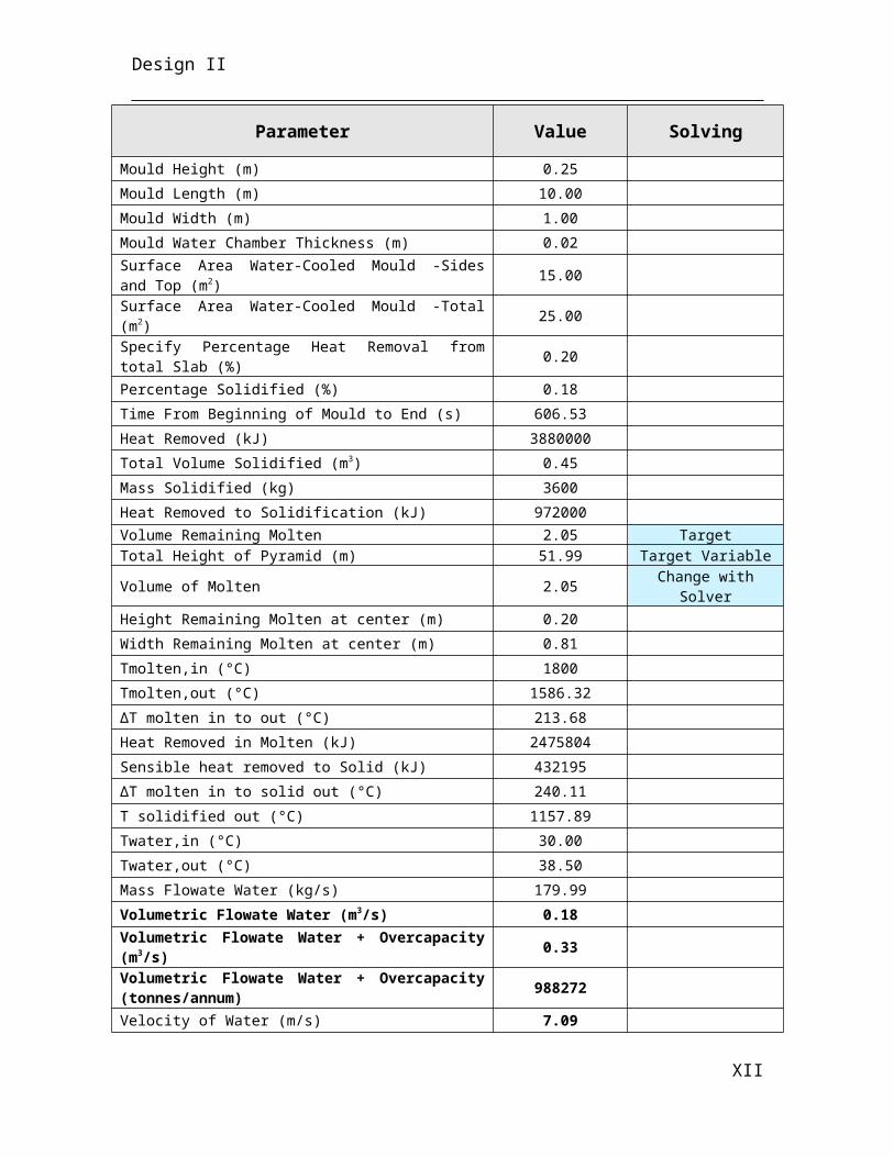
Design II
AOD feed prep
LD-03-301 (2)
Steel ladle for molten steel
transferLadle 7 m, 3 m, 7 m Carbon steel Continuous 18 m3 N/A PFD-03-004 $49,554 7 needed
AOD feed prep
LF-03-301 (2)
Ladle furnace for storing steel Ladle furnace 10 m, 3 m, 10 m Carbon steel Intermittent 17 m3 N/A PFD-03-004 $3,224,173 3 ladle furnaces
need + 1 spare
EAFLC-03-201 (2), LC-03-
202 (2)Slag car Ladle car Height: 4 m;
Dia: 2.33 m
Carbon steel / Magnesite-
chromite brickIntermittent 17 t/h N/A PFD-03-003 $40,116.80
EAFLD-03-201 (2), LD-03-
202 (2)Hot metal ladle Ladle Height: 5 m; Dia: 3
m
Carbon steel/ magnesite-
chromite brickIntermittent 313 t/h N/A PFD-03-003 111923.95
AOD reactor SP-03-301 Slag pot Ladle 4 m, 2 m, 4 m Carbon steel Intermittent 4 m3 N/A PFD-03-005 $48,279 3 + 4 spares
AOD reactor LD-03-301 Ladle for
stainless steel Ladle 9 m, 4 m, 8 m Carbon steel Intermittent 33 m3 N/A PFD-03-005 $49,554 4 + 4 spares
Launders
AOD reactor LA-03-301 Metal launder for
hot metal Launder 1 m, 2 m Carbon steel Intermittent 33 t/h N/A PFD-03-005 $1,254
EAF LA-03-203, LA-03-204 Slag launder Launder 1 m2 tap hole, 1 m
spoutMagnesite-
chromite brick Intermittent 17 t/h N/A PFD-03-003 included in EAF price
EAF LA-03-201, LA-03-202
Hot metal launder Launder 1 m2 tap hole, 1 m
spoutMagnesite-
chromite brick Intermittent 160 t/h N/A PFD-03-003 included in EAF price
Midrex Shaft Furnaces
Midrex furnace S-03-102 Midrex shaft
furnaceMidrex shaft
furnace 6.5 m, 6.5 m, 20 m Intermittent 55,000 m3/h PFD-03-003
Molds
Continuous Casting MD-03-401
Oscillating Water-Cooled
Mold
Double-Chamber Mold
10m x 1.04m x 0.29 m Copper Continuous
Stainless Steel: 120
t/h Water:
1200 m3/h
/ PFD-03-006cost under continuous
casting
Continuous Casting MD-03-402
Oscillating Water-Cooled
Mold
Double-Chamber Mold
10m x 1.04m x 0.29 m Copper Continuous
Stainless Steel: 120
t/h Water:
1200 m3/h
/ PFD-03-006cost under continuous
casting
Nozzles
63
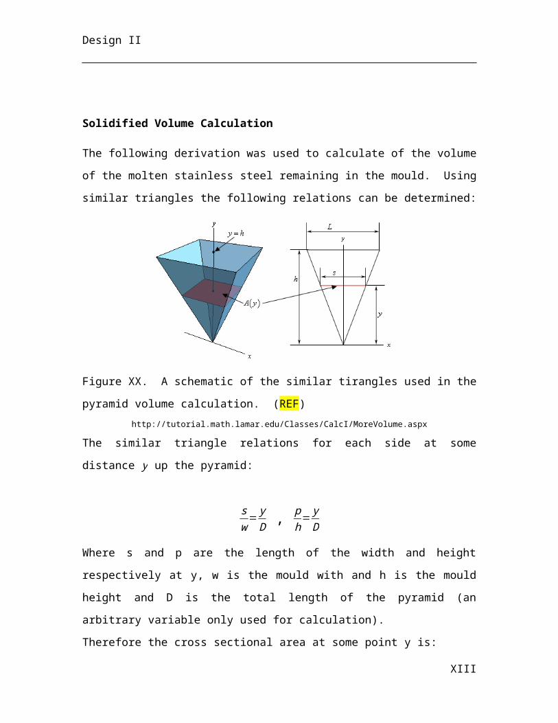
Design II
Continuous Casting NZ-03-401 Rod-Controlled
Stopper NozzleNozzle and
Stopper d-0.3m x h-0.5mHigh Purity Stabilised Zirconia
/ / / PFD-03-006cost under continuous
casting
Continuous Casting NZ-03-402 Rod-Controlled
Stopper NozzleNozzle and
Stopper d-0.3m x h-0.5mHigh Purity Stabilised Zirconia
/ / / PFD-03-006cost under continuous
casting
Pumps
EAF
PP-03-201, PP-03-202
Hydraulic compressors for
EAF mechanismsPump 2 m, 1 m, 1 m SS316 Intermittent 650 bar 1 MW P&ID No. 3 $1,000,000.00
Midrex boiler PP-03-101 Process water for
steam generation Pump 0.89 m, 0.51 m, 0.76 m SS316 Continuous 25 m3/h PFD-03-001
Midrex furnace PP-03-102 Process water for
scrubber Pump 0.89 m, 0.51 m, 0.76 m SS316 Intermittent 35 m3/h PFD-03-002
Continuous Casting
PP-03-401 A
Cooling Water Centrifugal Pump Pump / / Continuous 1200 m3/h 80 PFD-03-006 111,253.19
Multiple Stage Minimum
Required head: 24 m Impeller:
Closed
Continuous Casting
PP-03-401 B
Cooling Water Centrifugal Pump Pump / / Continuous 1200 m3/h 80 PFD-03-006 111,253.19
Multiple Stage Minimum
Required head: 24 m Impeller:
Closed
Continuous Casting
PP-03-402 A
Cooling Water Centrifugal Pump Pump / / Continuous 1200 m3/h 80 PFD-03-006 111,253.19
Multiple Stage Minimum
Required head: 24 m Impeller:
Closed
Continuous Casting
PP-03-402 B
Cooling Water Centrifugal Pump Pump / / Continuous 1200 m3/h 80 PFD-03-006 111,253.19
Multiple Stage Minimum
Required head: 24 m Impeller:
Closed
Continuous Casting
PP-03-403 A
Process Water Centrifugal Pump Pump / / Continuous 3150 m3/h 500 PFD-03-006 238,697.74
Mulitple Stage Minimum
Required head: 56 m Impeller:
Closed
Continuous Casting
PP-03-403 B
Process Water Centrifugal Pump Pump / / Continuous 3150 m3/h 500 PFD-03-006 238,697.74
Mulitple Stage Minimum
Required head: 56 m Impeller:
Closed
Continuous Casting
PP-03-404 A
Process Water Centrifugal Pump Pump / / Continuous 3150 m3/h 500 PFD-03-006 238,697.74
Mulitple Stage Minimum
Required head: 56 m Impeller:
Closed
64
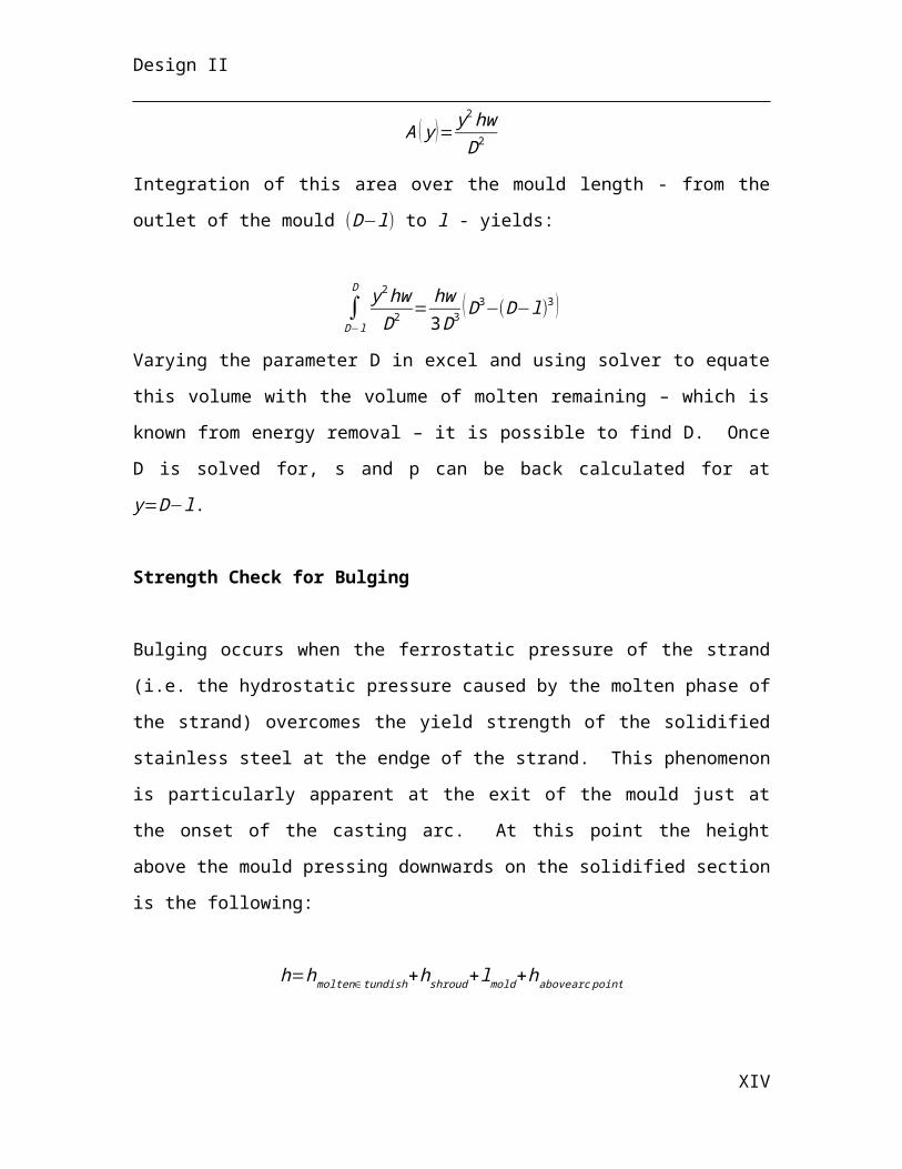
Design II
Continuous Casting
PP-03-404 B
Process Water Centrifugal Pump Pump / / Continuous 3150 m3/h 500 PFD-03-006 238,697.74
Mulitple Stage Minimum
Required head: 56 m Impeller:
Closed Racks
Continuous
Casting RA-03-401 Slab Collection Rack Rack 25 m x 10 m x 1 m / Continuous 4.21
slabs/h / PFD-03-007 352,200.00
Rails
EAF NA
Steel tracks for various rail cars and ladle cars
Tracks Length: 1000 m; Width: 1.8 m SS316 Intermittent N/A N/A N/A $420,000.00
Reformer
Reformer R-03-101
Steam reformer for syngas production
Reformer Length: 12 m Continuous 115 t/h PFD:03-001
Rollers
Continuous Casting RL-03-401 Power-Driven
Roller Roller d-0.4 m x l-0.25 m Carbon Steel Continuous / 100PFD-03-006 to PFD-03-
007
cost under continuous
castingRoll Speed 100 s-1
Continuous Casting RL-03-402 Power-Driven
Roller Roller d-0.4 m x l-0.25 m Carbon Steel Continuous / 100PFD-03-006 to PFD-03-
007
cost under continuous
castingRoll Speed 100 s-1
Continuous Casting RL-03-403 Power-Driven
Roller Roller d-0.4 m x l-0.25 m Carbon Steel Continuous / 100PFD-03-006 to PFD-03-
007
cost under continuous
castingRoll Speed 100 s-1
Continuous Casting RL-03-404 Power-Driven
Roller Roller d-0.4 m x l-0.25 m Carbon Steel Continuous / 100PFD-03-006 to PFD-03-
007
cost under continuous
castingRoll Speed 100 s-1
Continuous Casting RL-03-405 Power-Driven
Roller Roller d-0.4 m x l-0.25 m Carbon Steel Continuous / 100PFD-03-006 to PFD-03-
007
cost under continuous
castingRoll Speed 100 s-1
Continuous Casting RL-03-406 Power-Driven
Roller Roller d-0.4 m x l-0.25 m Carbon Steel Continuous / 100PFD-03-006 to PFD-03-
007
cost under continuous
castingRoll Speed 100 s-1
Continuous Casting RL-03-407 Power-Driven
Roller Roller d-0.4 m x l-0.25 m Carbon Steel Continuous / 100PFD-03-006 to PFD-03-
007
cost under continuous
castingRoll Speed 100 s-1
Continuous Casting RL-03-408 Power-Driven
Roller Roller d-0.4 m x l-0.25 m Carbon Steel Continuous / 100PFD-03-006 to PFD-03-
007
cost under continuous
castingRoll Speed 100 s-1
Continuous Casting RL-03-409 Power-Driven
Roller Roller d-0.4 m x l-0.25 m Carbon Steel Continuous / 100PFD-03-006 to PFD-03-
007
cost under continuous
castingRoll Speed 100 s-1
Continuous Casting RL-03-410 Power-Driven
Roller Roller d-0.4 m x l-0.25 m Carbon Steel Continuous / 100PFD-03-006 to PFD-03-
007
cost under continuous
castingRoll Speed 100 s-1
65
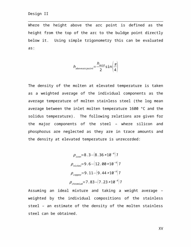
Design II
Continuous Casting RL-03-411 Power-Driven
Roller Roller d-0.4 m x l-0.25 m Carbon Steel Continuous / 100PFD-03-006 to PFD-03-
007
cost under continuous
castingRoll Speed 100 s-1
Continuous Casting RL-03-412 Power-Driven
Roller Roller d-0.4 m x l-0.25 m Carbon Steel Continuous / 100PFD-03-006 to PFD-03-
007
cost under continuous
castingRoll Speed 100 s-1
Continuous Casting RL-03-413 Power-Driven
Roller Roller d-0.4 m x l-0.25 m Carbon Steel Continuous / 100PFD-03-006 to PFD-03-
007
cost under continuous
castingRoll Speed 100 s-1
Continuous Casting RL-03-414 Power-Driven
Roller Roller d-0.4 m x l-0.25 m Carbon Steel Continuous / 100PFD-03-006 to PFD-03-
007
cost under continuous
castingRoll Speed 100 s-1
Continuous Casting RL-03-415 Power-Driven
Roller Roller d-0.4 m x l-0.25 m Carbon Steel Continuous / 100PFD-03-006 to PFD-03-
007
cost under continuous
castingRoll Speed 100 s-1
Continuous Casting RL-03-416 Power-Driven
Roller Roller d-0.4 m x l-0.25 m Carbon Steel Continuous / 100PFD-03-006 to PFD-03-
007
cost under continuous
castingRoll Speed 100 s-1
Continuous Casting RL-03-417 Power-Driven
Roller Roller d-0.4 m x l-0.25 m Carbon Steel Continuous / 100PFD-03-006 to PFD-03-
007
cost under continuous
castingRoll Speed 100 s-1
Continuous Casting RL-03-418 Power-Driven
Roller Roller d-0.4 m x l-0.25 m Carbon Steel Continuous / 100PFD-03-006 to PFD-03-
007
cost under continuous
castingRoll Speed 100 s-1
Continuous Casting RL-03-419 Power-Driven
Roller Roller d-0.4 m x l-0.25 m Carbon Steel Continuous / 100PFD-03-006 to PFD-03-
007
cost under continuous
castingRoll Speed 100 s-1
Continuous Casting RL-03-420 Power-Driven
Roller Roller d-0.4 m x l-0.25 m Carbon Steel Continuous / 100PFD-03-006 to PFD-03-
007
cost under continuous
castingRoll Speed 100 s-1
Continuous Casting RL-03-421 Power-Driven
Roller Roller d-0.4 m x l-0.25 m Carbon Steel Continuous / 100PFD-03-006 to PFD-03-
007
cost under continuous
castingRoll Speed 100 s-1
Continuous Casting RL-03-422 Power-Driven
Roller Roller d-0.4 m x l-0.25 m Carbon Steel Continuous / 100PFD-03-006 to PFD-03-
007
cost under continuous
castingRoll Speed 100 s-1
Continuous Casting RL-03-423 Power-Driven
Roller Roller d-0.4 m x l-0.25 m Carbon Steel Continuous / 100PFD-03-006 to PFD-03-
007
cost under continuous
castingRoll Speed 100 s-1
Continuous Casting RL-03-424 Power-Driven
Roller Roller d-0.4 m x l-0.25 m Carbon Steel Continuous / 100PFD-03-006 to PFD-03-
007
cost under continuous
castingRoll Speed 100 s-1
Continuous Casting RL-03-425 Power-Driven
Roller Roller d-0.4 m x l-0.25 m Carbon Steel Continuous / 100PFD-03-006 to PFD-03-
007
cost under continuous
castingRoll Speed 100 s-1
66
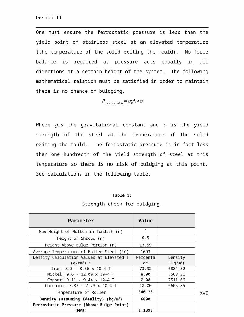
Design II
Continuous Casting RL-03-426 Power-Driven
Roller Roller d-0.4 m x l-0.25 m Carbon Steel Continuous / 100PFD-03-006 to PFD-03-
007
cost under continuous
castingRoll Speed 100 s-1
Continuous Casting RL-03-427 Power-Driven
Roller Roller d-0.4 m x l-0.25 m Carbon Steel Continuous / 100PFD-03-006 to PFD-03-
007
cost under continuous
castingRoll Speed 100 s-1
Continuous Casting RL-03-428 Power-Driven
Roller Roller d-0.4 m x l-0.25 m Carbon Steel Continuous / 100PFD-03-006 to PFD-03-
007
cost under continuous
castingRoll Speed 100 s-1
Continuous Casting RL-03-429 Power-Driven
Roller Roller d-0.4 m x l-0.25 m Carbon Steel Continuous / 100PFD-03-006 to PFD-03-
007
cost under continuous
castingRoll Speed 100 s-1
Continuous Casting RL-03-430 Power-Driven
Roller Roller d-0.4 m x l-0.25 m Carbon Steel Continuous / 100PFD-03-006 to PFD-03-
007
cost under continuous
castingRoll Speed 100 s-1
Continuous Casting RL-03-431 Power-Driven
Roller Roller d-0.4 m x l-0.25 m Carbon Steel Continuous / 100PFD-03-006 to PFD-03-
007
cost under continuous
castingRoll Speed 100 s-1
Continuous Casting RL-03-432 Power-Driven
Roller Roller d-0.4 m x l-0.25 m Carbon Steel Continuous / 100PFD-03-006 to PFD-03-
007
cost under continuous
castingRoll Speed 100 s-1
Continuous Casting RL-03-433 Power-Driven
Roller Roller d-0.4 m x l-0.25 m Carbon Steel Continuous / 100PFD-03-006 to PFD-03-
007
cost under continuous
castingRoll Speed 100 s-1
Continuous Casting RL-03-434 Power-Driven
Roller Roller d-0.4 m x l-0.25 m Carbon Steel Continuous / 100PFD-03-006 to PFD-03-
007
cost under continuous
castingRoll Speed 100 s-1
Continuous Casting RL-03-435 Power-Driven
Roller Roller d-0.4 m x l-0.25 m Carbon Steel Continuous / 100PFD-03-006 to PFD-03-
007
cost under continuous
castingRoll Speed 100 s-1
Continuous Casting RL-03-436 Power-Driven
Roller Roller d-0.4 m x l-0.25 m Carbon Steel Continuous / 100PFD-03-006 to PFD-03-
007
cost under continuous
castingRoll Speed 100 s-1
Continuous Casting RL-03-437 Power-Driven
Roller Roller d-0.4 m x l-0.25 m Carbon Steel Continuous / 100PFD-03-006 to PFD-03-
007
cost under continuous
castingRoll Speed 100 s-1
Continuous Casting RL-03-438 Power-Driven
Roller Roller d-0.4 m x l-0.25 m Carbon Steel Continuous / 100PFD-03-006 to PFD-03-
007
cost under continuous
castingRoll Speed 100 s-1
Continuous Casting RL-03-439 Power-Driven
Roller Roller d-0.4 m x l-0.25 m Carbon Steel Continuous / 100PFD-03-006 to PFD-03-
007
cost under continuous
castingRoll Speed 100 s-1
Continuous Casting RL-03-440 Power-Driven
Roller Roller d-0.4 m x l-0.25 m Carbon Steel Continuous / 100PFD-03-006 to PFD-03-
007
cost under continuous
castingRoll Speed 100 s-1
67
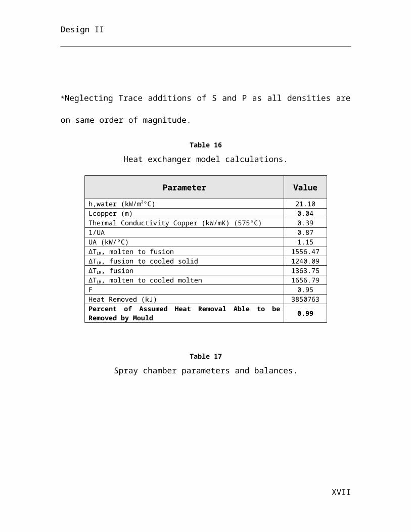
Design II
Continuous Casting RL-03-441 Power-Driven
Roller Roller d-0.4 m x l-0.25 m Carbon Steel Continuous / 100PFD-03-006 to PFD-03-
007
cost under continuous
castingRoll Speed 100 s-1
Continuous Casting RL-03-442 Power-Driven
Roller Roller d-0.4 m x l-0.25 m Carbon Steel Continuous / 100PFD-03-006 to PFD-03-
007
cost under continuous
castingRoll Speed 100 s-1
Continuous Casting RL-03-443 Power-Driven
Roller Roller d-0.4 m x l-0.25 m Carbon Steel Continuous / 100PFD-03-006 to PFD-03-
007
cost under continuous
castingRoll Speed 100 s-1
Continuous Casting RL-03-444 Power-Driven
Roller Roller d-0.4 m x l-0.25 m Carbon Steel Continuous / 100PFD-03-006 to PFD-03-
007
cost under continuous
castingRoll Speed 100 s-1
Continuous Casting RL-03-445 Power-Driven
Roller Roller d-0.4 m x l-0.25 m Carbon Steel Continuous / 100PFD-03-006 to PFD-03-
007
cost under continuous
castingRoll Speed 100 s-1
Continuous Casting RL-03-446 Power-Driven
Roller Roller d-0.4 m x l-0.25 m Carbon Steel Continuous / 100PFD-03-006 to PFD-03-
007
cost under continuous
castingRoll Speed 100 s-1
Continuous Casting RL-03-447 Power-Driven
Roller Roller d-0.4 m x l-0.25 m Carbon Steel Continuous / 100PFD-03-006 to PFD-03-
007
cost under continuous
castingRoll Speed 100 s-1
Continuous Casting RL-03-448 Power-Driven
Roller Roller d-0.4 m x l-0.25 m Carbon Steel Continuous / 100PFD-03-006 to PFD-03-
007
cost under continuous
castingRoll Speed 100 s-1
Continuous Casting RL-03-449 Power-Driven
Roller Roller d-0.4 m x l-0.25 m Carbon Steel Continuous / 100PFD-03-006 to PFD-03-
007
cost under continuous
castingRoll Speed 100 s-1
Continuous Casting RL-03-450 Power-Driven
Roller Roller d-0.4 m x l-0.25 m Carbon Steel Continuous / 100PFD-03-006 to PFD-03-
007
cost under continuous
castingRoll Speed 100 s-1
Continuous Casting RL-03-451 Power-Driven
Roller Roller d-0.4 m x l-0.25 m Carbon Steel Continuous / 100PFD-03-006 to PFD-03-
007
cost under continuous
castingRoll Speed 100 s-1
Continuous Casting RL-03-452 Power-Driven
Roller Roller d-0.4 m x l-0.25 m Carbon Steel Continuous / 100PFD-03-006 to PFD-03-
007
cost under continuous
castingRoll Speed 100 s-1
Continuous Casting RL-03-453 Power-Driven
Roller Roller d-0.4 m x l-0.25 m Carbon Steel Continuous / 100PFD-03-006 to PFD-03-
007
cost under continuous
castingRoll Speed 100 s-1
Continuous Casting RL-03-454 Power-Driven
Roller Roller d-0.4 m x l-0.25 m Carbon Steel Continuous / 100PFD-03-006 to PFD-03-
007
cost under continuous
castingRoll Speed 100 s-1
Continuous Casting RL-03-455 Power-Driven
Roller Roller d-0.4 m x l-0.25 m Carbon Steel Continuous / 100PFD-03-006 to PFD-03-
007
cost under continuous
castingRoll Speed 100 s-1
68
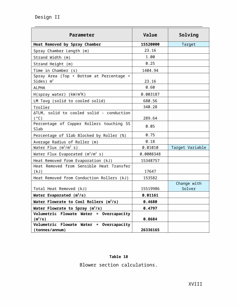
Design II
Continuous Casting RL-03-456 Power-Driven
Roller Roller d-0.4 m x l-0.25 m Carbon Steel Continuous / 100PFD-03-006 to PFD-03-
007
cost under continuous
castingRoll Speed 100 s-1
Continuous Casting RL-03-457 Power-Driven
Roller Roller d-0.4 m x l-0.25 m Carbon Steel Continuous / 100PFD-03-006 to PFD-03-
007
cost under continuous
castingRoll Speed 100 s-1
Continuous Casting RL-03-458 Power-Driven
Roller Roller d-0.4 m x l-0.25 m Carbon Steel Continuous / 100PFD-03-006 to PFD-03-
007
cost under continuous
castingRoll Speed 100 s-1
Scrubber
Midrex furnace S-03-101 Scrubber for dust
particles removalVenturi
Scrubber 1.5 m, 1.5 m, 3 m Intermittent 55,000 m3/h PFD-03-002
Spray Chambers
Continuous Casting SC-03-401 Arced Spray
ChamberMisting Spray
Chamber
Arc Length: 19.2 m Casting Radius:
12.2 m Straight Portion
Length: 4 m
Steel Continuous
Stainless Steel: 120
t/h Water:
3200 m3/h Air: 320
m3/h
/ PFD-03-006cost under continuous
casting
Number of Nozzles: 320 Nozzle Type:
1PM.013.16.17 Flat Fan Misting
Nozzle Nozzle Diameter: 0.005
m 4 Arced Roller
Zones 1 Flat Roller Zone
Continuous Casting SC-03-402 Arced Spray
ChamberMisting Spray
Chamber
Arc Length: 19.2 m Casting Radius:
12.2 m Straight Portion
Length: 4 m
Steel Continuous
Stainless Steel: 120
t/h Water:
3200 m3/h Air: 320
m3/h
/ PFD-03-006cost under continuous
casting
Number of Nozzles: 320 Nozzle Type:
1PM.013.16.17 Flat Fan Misting
Nozzle Nozzle Diameter: 0.005
m 4 Arced Roller
Zones 1 Flat Roller Zone
Tanks
Continuous Casting TA-03-401 Suspend Flux
Blow Tank
Bottom Discharge Blow Tank
d-0.2m x h-0.2m Carbon Steel Continuous .01 m3 air/h 0.5 t/h / PFD-03-006
cost under pneumatic conveyor
Continuous Casting TA-03-402 Suspend Flux
Blow Tank
Bottom Discharge Blow Tank
d-0.2m x h-0.2m Carbon Steel Continuous .01 m3 air/h 0.5 t/h / PFD-03-006
cost under pneumatic conveyor
Continuous Casting TA-03-403 Suspend Flux
Blow Tank
Bottom Discharge Blow Tank
d-0.2m x h-0.2m Carbon Steel Continuous .01 m3 air/h 0.5 t/h / PFD-03-006
cost under pneumatic conveyor
Continuous Casting TA-03-404 Suspend Flux
Blow Tank
Bottom Discharge Blow Tank
d-0.2m x h-0.2m Carbon Steel Continuous .01 m3 air/h 0.5 t/h / PFD-03-006
cost under pneumatic conveyor
Torches
69


![MakingIPEWork Final Rev[1]](https://img.pdfslide.us/doc/110x75/587f45f11a28ab43318b65cb/makingipework-final-rev1.jpg)


![Final MSR Rev[1]. C](https://img.pdfslide.us/doc/110x75/55cf9a82550346d033a2162f/final-msr-rev1-c.jpg)