Embed Size (px)
DESCRIPTION
Block Work
Citation preview
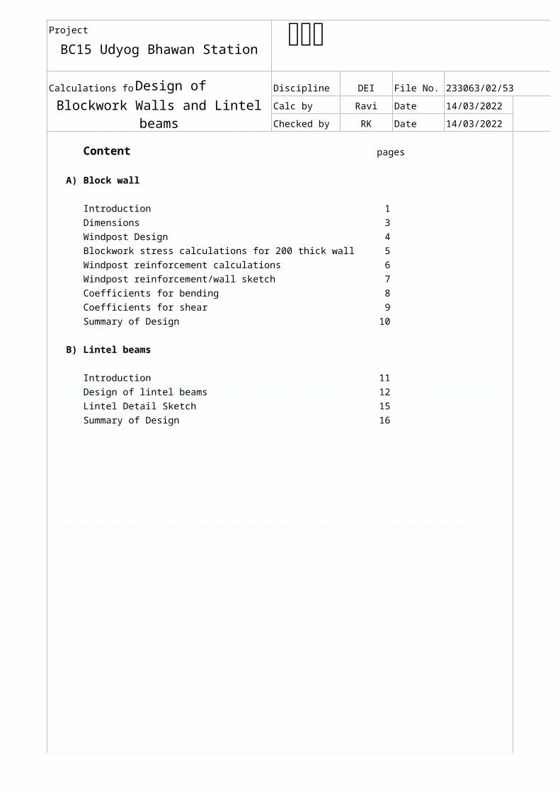
Project
BC15 Udyog Bhawan Station
Calculations for Design of Discipline DEI File No. 233063/02/53
Blockwork Walls and Lintel beamsCalc by Ravi Date 18/04/2023
Checked by RK Date 18/04/2023
Content pages
A) Block wall
Introduction 1
Dimensions 3
Windpost Design 4
Blockwork stress calculations for 200 thick wall 5
Windpost reinforcement calculations 6
Windpost reinforcement/wall sketch 7
Coefficients for bending 8
Coefficients for shear 9
Summary of Design 10
B) Lintel beams
Introduction 11
Design of lintel beams 12
Lintel Detail Sketch 15
Summary of Design 16
abc
Project
BC15 Udyog Bhawan Station
Calculations for Design of Discipline DEI File No. 233063/02/53
Blockwork Walls and Lintel beamsCalc by Ravi Date 18/04/2023
Checked by RK Date 18/04/2023
abc
Project
BC15 Udyog Bhawan Station
Calculations for Divn/Dept DEI File No. 233063/02/53
Blockwork Walls Calc by Ravi Date 03/03/2009 Sheet
Checked by RK Date 03/03/2009 1
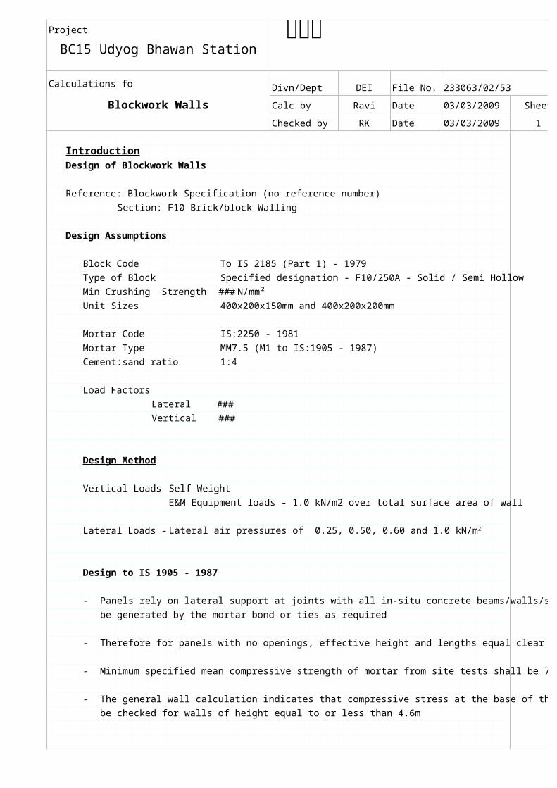
IntroductionDesign of Blockwork Walls
Reference: Blockwork Specification (no reference number)
Section: F10 Brick/block Walling
Design Assumptions
Block Code To IS 2185 (Part 1) - 1979
Type of Block Specified designation - F10/250A - Solid / Semi Hollow
Min Crushing Strength ### N/mm²
Unit Sizes 400x200x150mm and 400x200x200mm
Mortar Code IS:2250 - 1981
Mortar Type MM7.5 (M1 to IS:1905 - 1987)
Cement:sand ratio 1:4
Load Factors
Lateral ###
Vertical ###
Design Method
Vertical Loads - Self Weight
E&M Equipment loads - 1.0 kN/m2 over total surface area of wall
Lateral Loads -
Design to IS 1905 - 1987
- Panels rely on lateral support at joints with all in-situ concrete beams/walls/slabs. Support will
be generated by the mortar bond or ties as required
- Therefore for panels with no openings, effective height and lengths equal clear values
- Minimum specified mean compressive strength of mortar from site tests shall be 7.5N/mm²
- The general wall calculation indicates that compressive stress at the base of the wall need not
be checked for walls of height equal to or less than 4.6m
abc
Lateral air pressures of 0.25, 0.50, 0.60 and 1.0 kN/m2

Project
BC15 Udyog Bhawan Station
Calculations for Divn/Dept DEI File No. 233063/02/53
Blockwork Walls Calc by Ravi Date 18/04/2023 Sheet
Checked by RK Date 18/04/2023
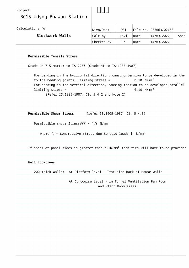
Permissible Tensile Stress
Grade MM 7.5 mortar to IS 2250 (Grade M1 to IS:1905-1987)
For bending in the horizontal direction, causing tension to be developed in the joints normal
to the bedding joints, limiting stress = 0.10 N/mm²
For bending in the vertical direction, causing tension to be developed parallel to bedding joints,
limiting stress = 0.10 N/mm²
(Refer IS:1905-1987, Cl. 5.4.2 and Note 2)
Permissible Shear Stress (refer IS:1905-1987 Cl. 5.4.3)
Permissible shear Stress = ### + N/mm²
If shear at panel sides is greater than 0.1N/mm² then ties will have to be provided
Wall Locations
200 thick walls: At Platform level - Trackside Back of House walls
At Concourse level - in Tunnel Ventilation Fan Room
and Plant Room areas
abc
fd/6
where fd = compressive stress due to dead loads in N/mm²
PM10 Jun 91
Project
BC15 Udyog Bhawan Station
Calculations for Discipline DEI File No. 233063/02/53
Dimensions (Typical)Calc by Ravi Date 18/04/2023 Sheet
Checked by RK Date 18/04/2023
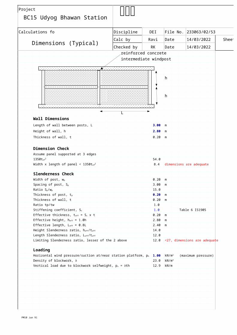
reinforced concrete
intermediate windpost
h
h
L
Wall Dimensions
Length of wall between posts, L 3.00 m
Height of wall, h 2.80 m
Thickness of wall, t 0.20 m
Dimension CheckAssume panel supported at 3 edges
54.0
8.4 dimensions are adequate
Slenderness Check0.20 m
3.00 m
15.0
0.20 m
Thickness of wall, t 0.20 m
Ratio tp/tw 1.0
1.0 Table 6 IS1905
0.20 m
2.80 m
2.40 m
14.0
12.0
Limiting Slenderness ratio, lesser of the 2 above 12.0 <27, dimensions are adequate
Loading1.00 (maximum pressure)
23.0
12.9 kN/m
abc
1350tef2
Width x length of panel < 1350tef2
Width of post, wp
Spacing of post, Sp
Ratio Sp/wp
Thickness of post, tp
Stiffening coefficient, Sc
Effective thickness, teff = Sc x t
Effective height, heff = 1.0h
Effective length, Leff = 0.8L
Height Slenderness ratio, heff/teff
Length Slenderness ratio, Leff/teff
Horizontal wind pressure/suction at/near station platform, ph kN/m2
Density of blockwork, d kN/m3
Vertical load due to blockwork selfweight, pv = dth
PM10 Jun 91
Project
BC15 Udyog Bhawan Station
Calculations for Discipline DEI File No. 233063/02/53
Dimensions (Typical)Calc by Ravi Date 18/04/2023 Sheet
Checked by RK Date 18/04/2023
abc
PM10 Jun 91
Project
BC15 Udyog Bhawan Station
Calculations for Divn/Dept DEI File No. 233063/02/53
Wind-Post for Blockwork WallsCalc by Ravi Date 18/04/2023 Sheet
Checked by RK Date 18/04/2023
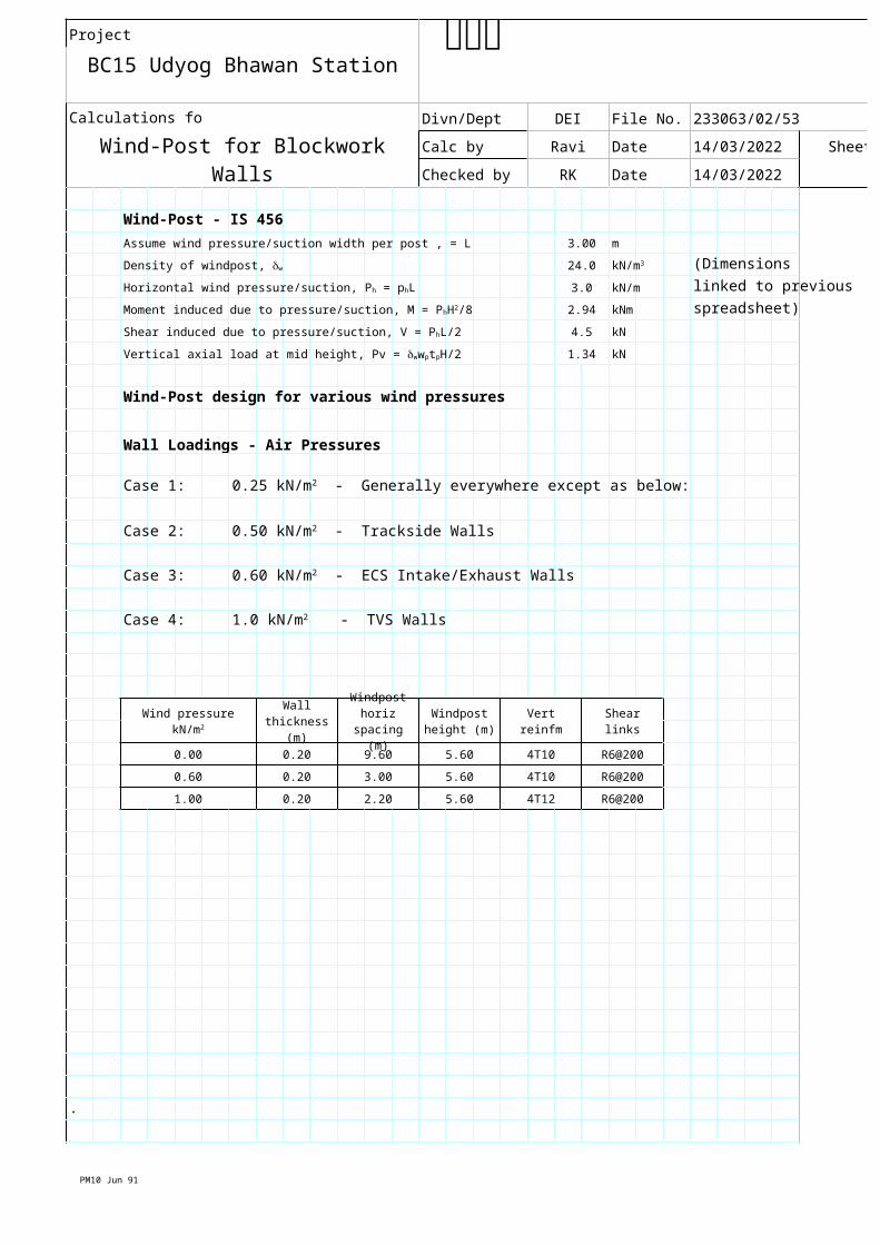
Wind-Post - IS 456
Assume wind pressure/suction width per post , = L 3.00 m
24.0 (Dimensions
3.0 kN/m linked to previous
2.94 kNm spreadsheet)
4.5 kN
1.34 kN
Wind-Post design for various wind pressures
Wall Loadings - Air Pressures
Case 1:
Case 2:
Case 3:
Case 4:
Vert reinfm Shear links
0.00 0.20 9.60 5.60 4T10 R6@200
0.60 0.20 3.00 5.60 4T10 R6@200
1.00 0.20 2.20 5.60 4T12 R6@200
.
abc
Density of windpost, dw kN/m3
Horizontal wind pressure/suction, Ph = phL
Moment induced due to pressure/suction, M = PhH2/8
Shear induced due to pressure/suction, V = PhL/2
Vertical axial load at mid height, Pv = dwwptpH/2
0.25 kN/m2 - Generally everywhere except as below:
0.50 kN/m2 - Trackside Walls
0.60 kN/m2 - ECS Intake/Exhaust Walls
1.0 kN/m2 - TVS Walls
Wind pressure kN/m2Wall
thickness (m)
Windpost horiz
spacing (m)
Windpost height (m)
PM10 Jun 91
Project
BC15 Udyog Bhawan Station
Calculations for Divn/Dept DEI File No. 233063/02/53
Wind-Post for Blockwork WallsCalc by Ravi Date 18/04/2023 Sheet
Checked by RK Date 18/04/2023
abc
document.xls
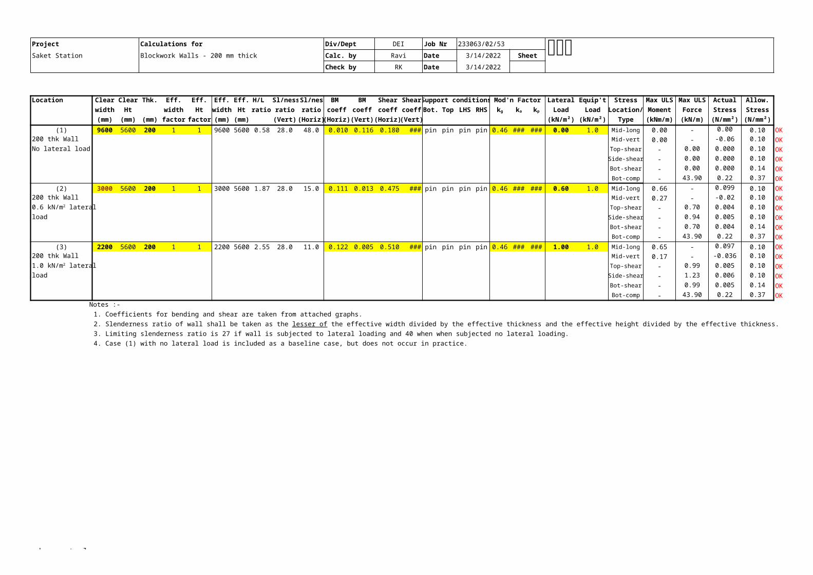
Project Calculations for Div/Dept DEI Job Nr 233063/02/53
Saket Station Blockwork Walls - 200 mm thick Calc. by Ravi Date 4/18/2023 Sheet
Check by RK Date 4/18/2023
Location Clear Clear Thk. Eff. Eff. Eff. Eff. H/L Sl/ness Sl/ness BM BM Shear Shear Support conditions Mod'n Factor Lateral Equip't Stress Max ULS Max ULS Actual Allow.
width Ht width Ht width Ht ratio ratio ratio coeff coeff coeff coeff Bot. Top LHS RHS Load Load Location/ Moment Force Stress Stress
(mm) (mm) (mm) factor factor (mm) (mm) (Vert) (Horiz) (Horiz) (Vert) (Horiz) (Vert) (kN/m²) (kN/m²) Type (kNm/m) (kN/m) (N/mm²) (N/mm²)
(1) 9600 5600 200 1 1 9600 5600 0.58 28.0 48.0 0.010 0.116 0.180 0.490 pin pin pin pin 0.46 1.00 1.10 0.00 1.0 Mid-long 0.00 - 0.00 0.10 OK
200 thk Wall Mid-vert 0.00 - -0.06 0.10 OK
No lateral load Top-shear - 0.00 0.000 0.10 OK
Side-shear - 0.00 0.000 0.10 OK
Bot-shear - 0.00 0.000 0.14 OK
Bot-comp - 43.90 0.22 0.37 OK
(2) 3000 5600 200 1 1 3000 5600 1.87 28.0 15.0 0.111 0.013 0.475 0.190 pin pin pin pin 0.46 1.00 1.10 0.60 1.0 Mid-long 0.66 - 0.099 0.10 OK modified
200 thk Wall Mid-vert 0.27 - -0.02 0.10 OK
Top-shear - 0.70 0.004 0.10 OK
load Side-shear - 0.94 0.005 0.10 OK
Bot-shear - 0.70 0.004 0.14 OK
Bot-comp - 43.90 0.22 0.37 OK
(3) 2200 5600 200 1 1 2200 5600 2.55 28.0 11.0 0.122 0.005 0.510 0.160 pin pin pin pin 0.46 1.00 1.10 1.00 1.0 Mid-long 0.65 - 0.097 0.10 OK
200 thk Wall Mid-vert 0.17 - -0.036 0.10 OK
Top-shear - 0.99 0.005 0.10 OK
load Side-shear - 1.23 0.006 0.10 OK
Bot-shear - 0.99 0.005 0.14 OK
Bot-comp - 43.90 0.22 0.37 OK
Notes :-
1. Coefficients for bending and shear are taken from attached graphs.
3. Limiting slenderness ratio is 27 if wall is subjected to lateral loading and 40 when when subjected no lateral loading.
4. Case (1) with no lateral load is included as a baseline case, but does not occur in practice.
abc
kg ka kp
0.6 kN/m2 lateral
1.0 kN/m2 lateral
2. Slenderness ratio of wall shall be taken as the lesser of the effective width divided by the effective thickness and the effective height divided by the effective thickness.
PM10 Jun 91 document.xls
Project
Saket Station
Calculations for Divn/Dept DEI File No. 233063/02/53
BC15 Udyog Bhawan Station Calc by Ravi Date 18/04/2023 Sheet
Checked by RK Date 18/04/2023
Size of Column 200 mm by 200 mm (b x D)
Concrete Grade 35 Steel Grade 415
2800 mm
2240
SLS ULS
1.3 2.0
Moment in the direction of Larger dimension (Top) (kNm) 0.0 0.0
Moment in the direction of Larger dimension (Bott) (kNm) 0.0 0.0
Moment in the direction of Shorter dimension (Top) (kNm) 0.0 0.0
Moment in the direction of Shorter dimension (Bott) (kNm) 0.0 4.4
11 <12 - Short Column
11 <12 - Short Column Therefore the Column is Short
ex = lu / 500 + D / 30 = 12 mm < 20 0.0 kNm
ey = lu / 500 + b / 30 = 12 mm < 20 0.0 kNm
Provide 4 no. 12 mm dia. Bars with 40 mm cover and 6 mm links
452 1.1 %
0.001 0.032
40,000
623 + 141 = 764 kN
2 / 764 = 0.00 1.0
d' / D (about xx-axis) = 0.23
Hence Chart or Table for d' / D = 0.20 will be used (Chart Numbe 46 & 45 to extrapolate)
0.045
13 kNm 0.00
0.00 - including moment due to eccentricity
d' / b (about yy-axis) = 0.23
Hence Chart or Table for d' / D = 0.20 will be used (Chart Numbe 46 & 45 to extrapolate)
0.045
13 kNm 0.35
0.35 - including moment due to eccentricity
From IS 456:2000 Clause 39.6:
= 0.350 <1 therefore OK based on min. BM in long (x) direction
= 0.350 <1 therefore OK based on min. BM in short (y) direction
abc
N/mm2 N/mm2
Unsupported Length, lu =
Effective Length for Bending Parallel to Larger Dimensions, le = mm (based on 0.80 lu)
Axial Load, Pu (kN)
le / D =
le / b =
20mm therefore ex = mm, and Mex =
20mm therefore ey = mm, and Mey =
Therefore Area of Steel As = mm2, and p =
Pu / fck b D = and p / fck =
Ag = mm2
From 39.6, Puz = 0.45fck x Ac + 0.75fy x Asc =
and Pu / Puz = Therefore, an =
Mux1 / fck bD2 =
Hence, Mux1 = and Mux / Mux1 =
Muy1 / fck Db2 =
Hence, Muy1 = and Muy / Muy1 =
(Mux / Mux1)an + (Muy / Muy1)an
PM10 Jun 91
Project
BC15 Udyog Bhawan Station
Calculations for Divn/Dept DEI File No. 233063/02/53
WindPost & Beam DetailsCalc by Ravi Date 18/04/2023 Sheet
Checked by RK Date 18/04/2023
20mm gap with
intumescent sealant
and compressible filler
h
h
Elevation 4-T10
(n.t.s) 200
R6 Link @ 200
### Section C - CR6 Link @ 200 (n.t.s)
150/200
4T10 or 4T12
Section B - B
(n.t.s)
BS 6073-1 for precast masonary concrete block
BS 1289-1 for concrete flue block
abc
structural slab
structural slab
BB
C
PM10 Jun 91
Project
BC15 Udyog Bhawan Station
Calculations for Divn/Dept DEI File No. 233063/02/53
WindPost & Beam DetailsCalc by Ravi Date 18/04/2023 Sheet
Checked by RK Date 18/04/2023
abc
Project
BC15 Udyog Bhawan Station
Calculations for Divn/Dept DEI File No. 233063/02/53
Blockwork WallsCalc by Ravi Date 18/04/2023 Sheet
Checked by RK Date 18/04/2023 8 of 10
abc
Project
BC15 Udyog Bhawan Station
Calculations for Divn/Dept DEI File No. 233063/02/53
Blockwork WallsCalc by Ravi Date 18/04/2023 Sheet
Checked by RK Date 18/04/2023 9 of 10
abc

Project
BC15 Udyog Bhawan Station
Calculations for Divn/Dept DEI File No. 233063/02/53
Wind-Post for Blockwork WallsCalc by Ravi Date 18/04/2023 Sheet
Checked by RK Date 18/04/2023 10 of 10
Summary of Design
h
h
windposts L
0.00 0.20 9.60 5.60 4T10 R6@200
0.60 0.20 3.00 5.60 4T10 R6@200
1.00 0.20 2.20 5.60 4T12 R6@200
Notes
1 Blockwork compressive strength 7.5 N/mm2
2 Concrete compressive strength 35 N/mm2
3 Reinforcement yield stress 415 N/mm2
4 Mortar grade M2 to IS 2250
###
R6 Link @ 200
150/200
4T12/4T10
Section thro' Windpost
(n.t.s)
abc
Wind pressure kN/m2Wall
thickness (m)
Windpost horiz
spacing L(m)
Windpost height (m)
Windpost Vert reinfm
Windposts Shear links
slab
slab
blockwork wall
colu
mn
colu
mn
column
PM10 Jun 91
Project
BC15 Udyog Bhawan Station
Calculations for Divn/Dept DEI File No. 233063/02/53
Lintel DetailCalc by Ravi Date 18/04/2023 Sheet
Checked by RK Date 18/04/2023
opening
opening
h - dimension varies up to a maximum value of 4.0m to accommodate
openings and to satisfy the slenderness ratio requirement
b - bearing length shall not be less than 90 mm or one-tenth of the span whichever is greater
Depth R8 Link
Varies 4T10/4T12/4T16
for span up to max. of 4.0m
Section C - C
(n.t.s)
abc
structural slab
structural slab
b
C
C
0
0
PM10 Jun 91
Project
BC15 Udyog Bhawan Station
Calculations for Divn/Dept DEI File No. 233063/02/53
Lintel DetailCalc by Ravi Date 18/04/2023 Sheet
Checked by RK Date 18/04/2023
abc