Embed Size (px)
Citation preview

Technical Report Documentation Page
1. Report No. FHWA/TX-08/0-4811-1
2. Government Accession No.
3. Recipient’s Catalog No.
4. Title and Subtitle Design of Composite Steel Beams for Bridges
5. Report Date January 2008
6. Performing Organization Code 7. Author(s)
J. A. Yura, E.R. Methvin, and M. D. Engelhardt 8. Performing Organization Report No.
0-4811-1
9. Performing Organization Name and Address Center for Transportation Research The University of Texas at Austin 3208 Red River, Suite 200 Austin, TX 78705-2650
10. Work Unit No. (TRAIS) 11. Contract or Grant No.
0-4811
12. Sponsoring Agency Name and Address Texas Department of Transportation Research and Technology Implementation Office P.O. Box 5080 Austin, TX 78763-5080
13. Type of Report and Period Covered Technical Report
September 2004–August 2005 14. Sponsoring Agency Code
15. Supplementary Notes Project performed in cooperation with the Texas Department of Transportation and the Federal Highway Administration.
16. Abstract Current AASHTO bridge specifications require that composite beams have sufficient shear studs to fully
yield the steel beam cross section in tension. The large number of studs required is independent of the loading on the bridge. It is recommended that partial composite design as used in building specifications be permitted. It is shown that 85% of the full composite strength can be achieved with 40% fewer studs.
The minimum stud spacing requirements in AASHTO were compared with the requirements in other design specifications. Additional research was recommended to evaluate the possibility of relaxing the current minimum requirement. It was shown that the current AASHTO fatigue requirements for stud design are conservative compared to the most recent research but no change is recommended.
17. Key Words AASHTO, bridge specifications, composite steel bridge beams
18. Distribution Statement No restrictions. This document is available to the public through the National Technical Information Service, Springfield, Virginia 22161; www.ntis.gov.
19. Security Classif. (of report) Unclassified
20. Security Classif. (of this page) Unclassified
21. No. of pages 36
22. Price
Form DOT F 1700.7 (8-72) Reproduction of completed page authorized

Design of Composite Steel Beams for Bridges J. A. Yura E.R. Methvin M. D. Engelhardt CTR Technical Report: 0-4811-1 Report Date: January 2008 Project: 0-4811 Project Title: Shear Connectors for Composite Steel Beams—Strength Limit State Sponsoring Agency: Texas Department of Transportation Performing Agency: Center for Transportation Research at The University of Texas at Austin Project performed in cooperation with the Texas Department of Transportation and the Federal Highway Administration.
iv
Center for Transportation Research The University of Texas at Austin 3208 Red River Austin, TX 78705 www.utexas.edu/research/ctr Copyright (c) 2008 Center for Transportation Research The University of Texas at Austin All rights reserved Printed in the United States of America
v
Disclaimers Author's Disclaimer: The contents of this report reflect the views of the authors, who
are responsible for the facts and the accuracy of the data presented herein. The contents do not necessarily reflect the official view or policies of the Federal Highway Administration or the Texas Department of Transportation (TxDOT). This report does not constitute a standard, specification, or regulation.
Patent Disclaimer: There was no invention or discovery conceived or first actually reduced to practice in the course of or under this contract, including any art, method, process, machine manufacture, design or composition of matter, or any new useful improvement thereof, or any variety of plant, which is or may be patentable under the patent laws of the United States of America or any foreign country.
Engineering Disclaimer NOT INTENDED FOR CONSTRUCTION, BIDDING, OR PERMIT PURPOSES.
Project Engineer: J. A. Yura
Professional Engineer License State and Number: Texas No. 29859 P. E. Designation: Research Supervisor

vi
Acknowledgments We greatly appreciate the financial support from the Texas Department of Transportation that made this project possible. The support of the project director, J. Holt, and program coordinators, T. Chase and T. Stout is also very much appreciated.
vii
Table of Contents
Chapter 1. Static Strength of Composite Beams ........................................................................ 1 1.1 Background and Scope ..........................................................................................................1 1.2 Composite Design Philosophy ...............................................................................................2 1.3 Effect of Studs .......................................................................................................................3 1.4 Suggested Implementation of Partial-Composite Design for Steel Bridges ..........................4
Chapter 2. Deflections of Composite Steel Beams ..................................................................... 7 2.1 Introduction ............................................................................................................................7 2.2 Deflection Calculations for Composite Beams ......................................................................7
2.2.1 Deflection Calculations for Full Composite Beams ...................................................... 7 2.2.2 Deflection Calculations for Partial Composite Beams .................................................. 8
2.3 Recommendations for Predicting Deflections .....................................................................11
Chapter 3. Minimum and Maximum Spacing of Shear Connectors ..................................... 13 3.1 Stud Spacing Limits in Design Specifications .....................................................................13 3.2 Basis for Maximum Spacing ................................................................................................13 3.3 Basis for Minimum Spacing ................................................................................................14 3.4 Summary of Shear Connector Spacing and Recommendations ..........................................15
Chapter 4. Fatigue Behavior of Shear Studs ............................................................................ 17 4.1 Introduction ..........................................................................................................................17 4.2 AASHTO LRFD Fatigue Design of Shear Connectors .......................................................17
4.2.1 AASHTO Provisions ................................................................................................... 17 4.2.2 Slutter and Fisher (1966) Research .............................................................................. 18
4.3 Fatigue Tests of Composite Beams .....................................................................................19 4.4 Sr-N Relationship in Specifications .....................................................................................19 4.5 Effects of Low-Cycle Fatigue ..............................................................................................20 4.6 Large Shear Studs ................................................................................................................21 4.7 Summary and Recommendations ........................................................................................22
Chapter 5. Summary of Recommendations for Composite Steel Bridge Beams .................. 23
References .................................................................................................................................... 25

viii
ix
List of Tables
Table 2.1: Average (range) % of variation between actual and calculated deflection ................. 10
List of Figures
Figure 1.1: Example of plastic theory ............................................................................................. 3
Figure 1.2: Effect of number of studs on bending strength ............................................................ 3
Figure 2.1: Typical load displacement curve for a partially-composite beam ................................ 9
Figure 2.2: Comparisons of effective moments of inertia ............................................................ 11
Figure 4.1: Estimated line of regression for push-out tests (Slutter and Fisher 1966) ................. 18
Figure 4.2: Comparison of estimated fatigue lives ....................................................................... 20
Figure 4.3: Suggested fatigue life equations for 7/8 and 1 ¼-inch studs ...................................... 22

x
1
Chapter 1. Static Strength of Composite Beams
1.1 Background and Scope The AASHTO LRFD Bridge Design Specifications (American Association of State Highway and Transportation Officials [AASHTO] 1998) provides rules for strength design of shear connectors for steel composite beams (LRFD refers to load and resistance factor design). These current rules require that sufficient shear studs be provided to develop the full composite strength of the steel beam. That is, shear studs must be provided to develop the full capacity of the cross-section, regardless of the actual loads on the beam. If the full composite flexural capacity of the cross-section is not needed to resist the design loads, then potentially many more studs are provided than actually needed. This is inconsistent with AASHTO rules for composite concrete beams. These current AASHTO rules for composite steel beams may require an excessive number of studs that can be difficult to place without violating current rules for minimum stud spacing, and may pose particular problems for TxDOT standard steel beam spans. For the design of composite steel beams in buildings, the AISC Specification for Structural Steel Buildings (American Institute of Steel Construction [AISC] 2005) does not require that shear connectors be designed to develop the full composite capacity of the cross-section. Rather, the AISC Specification permits composite steel beams to be designed as partially composite so the number of shear studs can be chosen based on the actual loading on the beam. For cases where full composite strength is not needed, the use of partial composite design can result in a substantial decrease in the required number of shear studs. Partial composite construction has been used in the building industry since 1969 and the majority of composite beams used in current building design practice are designed as partial composite beams. The AISC Specification has design recommendations for calculation of both strength and deflections of partial composite beams. Interestingly, the 13th edition of the AASHTO Standard Specifications for Highway Bridges in 1983 permitted the calculation of the bending strength based on the number of studs provided. AASHTO used the same formulas that appeared in the 1978 AISC specification. Unfortunately, the AASHTO provisions for stud design still required that the number of studs be based on the cross-section properties, not the required strength. AASHTO removed the partial composite bending strength provision in 1995 with the comment, “This equation is redundant because… partial composite action is not currently permitted by AASHTO.” If that was the case, it seems strange that the provision was adopted in 1983. A more likely explanation is that composite action is not fully understood. In order to address the issues and apparent inconsistencies in the AASHTO shear connector strength design requirements for composite steel beams as noted earlier, four areas of composite beam design were investigated: stud design philosophy in this chapter, deflections in Chapter 2, stud spacing requirements and limitations in Chapter 3, and stud fatigue behavior in Chapter 4. Recommendations are given in each of these chapters and are summarized in Chapter 5. A primary objective is to determine if changes are warranted that would permit shear connectors to be designed based on required strength rather than based on cross-section properties.
2
1.2 Composite Design Philosophy
Prior to 1960, both bending strength and stud design for composite beams were based on elastic theory. For bending strength and stiffness, the steel and concrete slab cross section is converted to an equivalent transformed steel section. The shear flow, ν, required for determining the number of studs is determined from the classic shear equation,
cI
VQ=ν (1.1)
where V = shear force from the loading, Q = first moment of the area of concrete deck about the neutral axis of the composite section and Ic = transformed moment of inertia. The spacing of the shear connectors is determined by dividing the connector strength by the shear flow. The shear flow will change along the member, so the spacing changes as the shear flow changes. For bridges, shear studs must be designed for static strength and fatigue strength. In AASHTO the elastic theory is used in the design of shear connectors for fatigue strength as discussed in Chapter 4.
Tests (Slutter and Driscoll 1965) showed that elastic theory for determining the stud shear requirement for bending ultimate strength was very conservative and that the studs could be distributed uniformly along the length. So in 1961 the design philosophy for studs changed to a plastic theory approach even though the bending strength was still based on elastic concepts. The total shear force Vh along the interface between the steel beam and the concrete slab studs design is given as the lesser of :
ysh fAV = (1.2)
or cch AfV '85.0= (1.3) where As = area of the steel beam, fy = yield strength of the steel beam, ='
cf compressive strength of the concrete and Ac = effective area of the concrete slab. The plastic approach assumes that slip will occur along the interface so the total shear force is distributed evenly among all the studs. This plastic shear philosophy is adopted currently in both AASHTO and AISC specifications. The inconsistency of elastic theory for bending and plastic theory for shear remained until 1985 when the AISC-LRFD specification adopted the plastic moment Mp for the bending strength of a composite section. AASHTO followed suite when the first edition of AASHTO-LRFD bridge specification was issued in 1991. The problem of using just Equations 1.2 and 1.3 for stud design was recognized by AISC in 1969, especially when the beam sizes were increased due to stiffness, aesthetics, or economic considerations, rather than strength. If the beam size increased, then more studs were required. The 1969 AISC Specification introduced a concept called incomplete composite action with Seff defined as the effective section modulus. Seff was a function hh VV ′ where hV ′ is the design shear force. For a given bending strength requirement, Seff , determined from the loading, hV ′ could be determined. The word incomplete was changed to partial in 1978. The partial composite concept was extended to the plastic stress distribution adopted in the AISC specification in 1985 and
3
remains unchanged in AISC (2005). The bending strength of a partially composite beam is discussed in the following section.
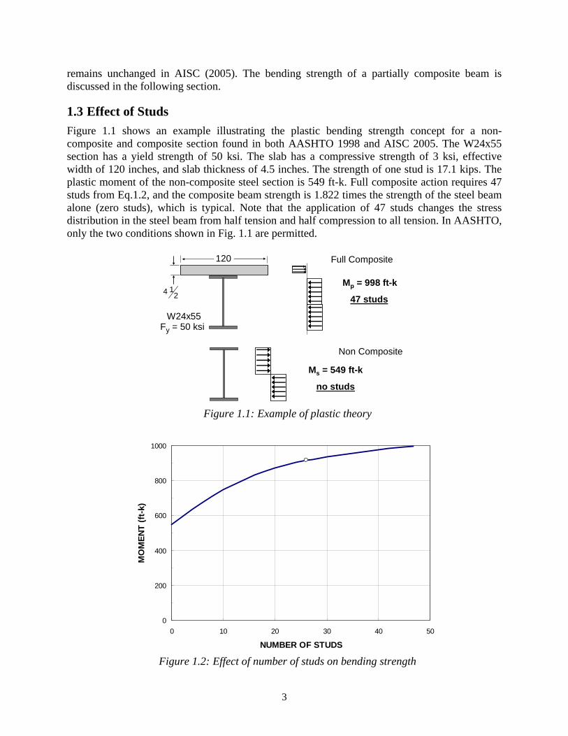
1.3 Effect of Studs Figure 1.1 shows an example illustrating the plastic bending strength concept for a non-composite and composite section found in both AASHTO 1998 and AISC 2005. The W24x55 section has a yield strength of 50 ksi. The slab has a compressive strength of 3 ksi, effective width of 120 inches, and slab thickness of 4.5 inches. The strength of one stud is 17.1 kips. The plastic moment of the non-composite steel section is 549 ft-k. Full composite action requires 47 studs from Eq.1.2, and the composite beam strength is 1.822 times the strength of the steel beam alone (zero studs), which is typical. Note that the application of 47 studs changes the stress distribution in the steel beam from half tension and half compression to all tension. In AASHTO, only the two conditions shown in Fig. 1.1 are permitted.
W24x55
14 2
120
Fy = 50 ksi
Ms = 549 ft-k
no studs
Mp = 998 ft-k
47 studs
Full Composite
Non Composite
Figure 1.1: Example of plastic theory
0
200
400
600
800
1000
0 10 20 30 40 50
NUMBER OF STUDS
MO
MEN
T (f
t-k)
Figure 1.2: Effect of number of studs on bending strength
4
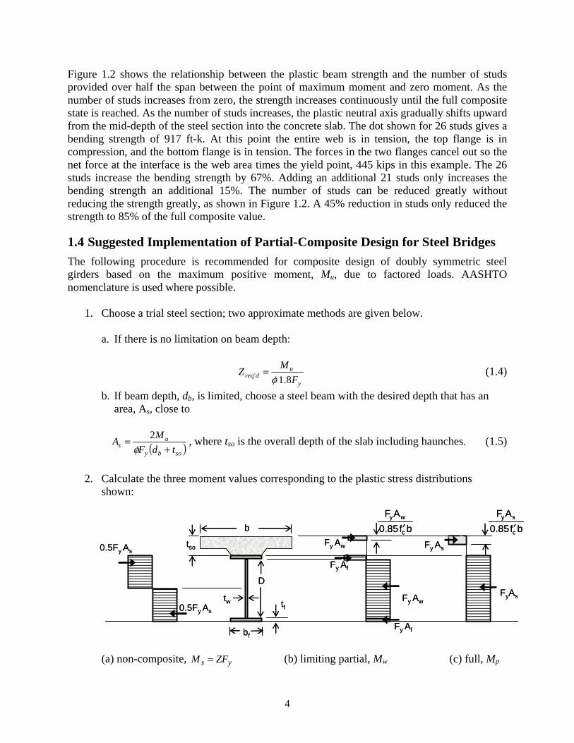
Figure 1.2 shows the relationship between the plastic beam strength and the number of studs provided over half the span between the point of maximum moment and zero moment. As the number of studs increases from zero, the strength increases continuously until the full composite state is reached. As the number of studs increases, the plastic neutral axis gradually shifts upward from the mid-depth of the steel section into the concrete slab. The dot shown for 26 studs gives a bending strength of 917 ft-k. At this point the entire web is in tension, the top flange is in compression, and the bottom flange is in tension. The forces in the two flanges cancel out so the net force at the interface is the web area times the yield point, 445 kips in this example. The 26 studs increase the bending strength by 67%. Adding an additional 21 studs only increases the bending strength an additional 15%. The number of studs can be reduced greatly without reducing the strength greatly, as shown in Figure 1.2. A 45% reduction in studs only reduced the strength to 85% of the full composite value.
1.4 Suggested Implementation of Partial-Composite Design for Steel Bridges The following procedure is recommended for composite design of doubly symmetric steel girders based on the maximum positive moment, Mu, due to factored loads. AASHTO nomenclature is used where possible.
1. Choose a trial steel section; two approximate methods are given below.
a. If there is no limitation on beam depth:
y
udreq F
MZ8.1' φ
= (1.4)
b. If beam depth, db, is limited, choose a steel beam with the desired depth that has an area, As, close to
( )soby
us tdF
MA+
=φ
2 , where tso is the overall depth of the slab including haunches. (1.5)
2. Calculate the three moment values corresponding to the plastic stress distributions
shown:
(a) non-composite, ys ZFM = (b) limiting partial, Mw (c) full, Mp
b
tso
D
tw
Fy Af
Fy Afbf
tfFyAsFy Aw
Fy Aw Fy As0.5Fy As
0.5Fy As
bf0.85AF
c
wy
′ bf0.85AF
c
sy
′b
tso
D
tw
Fy Af
Fy Afbf
tfFyAsFy Aw
Fy Aw Fy As0.5Fy As
0.5Fy As
bf0.85AF
c
wy
′ bf0.85AF
c
sy
′
5
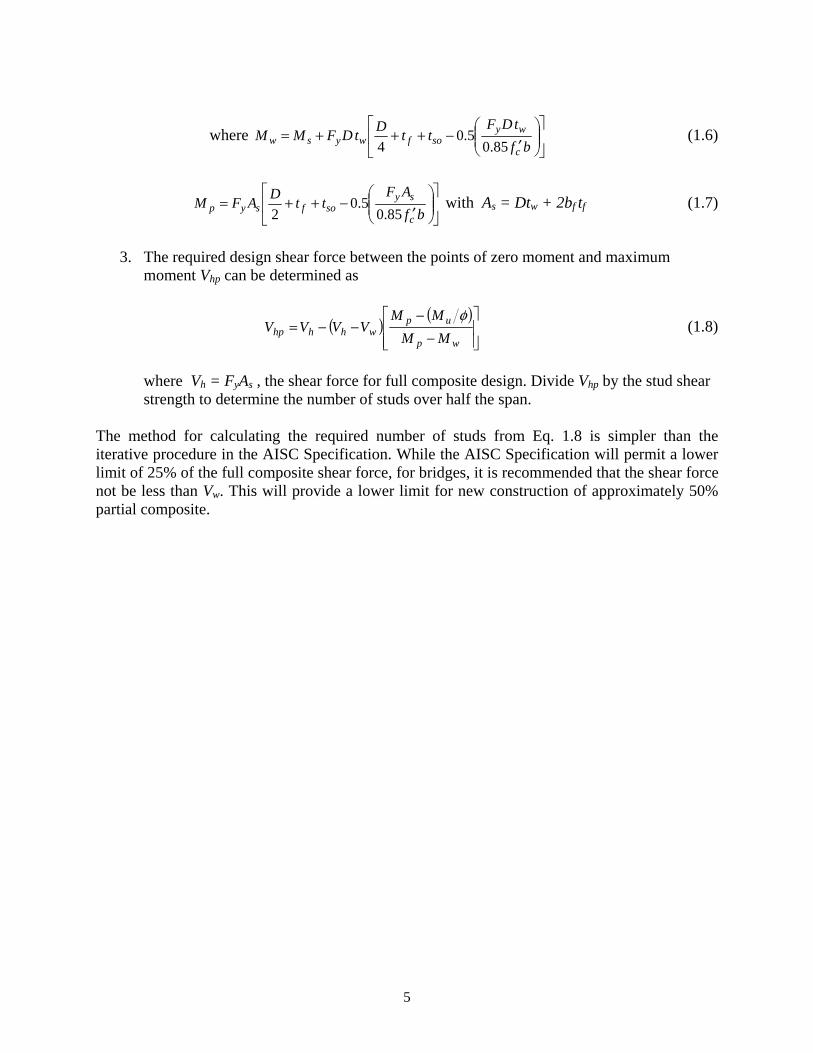
where ⎥⎦
⎤⎢⎣
⎡⎟⎟⎠
⎞⎜⎜⎝
⎛′
−+++=bf
tDFttDtDFMM
c
wysofwysw 85.0
5.04
(1.6)
⎥⎦
⎤⎢⎣
⎡⎟⎟⎠
⎞⎜⎜⎝
⎛′
−++=bf
AFttDAFM
c
sysofsyp 85.0
5.02
with As = Dtw + 2bf tf (1.7)
3. The required design shear force between the points of zero moment and maximum
moment Vhp can be determined as
( ) ( )⎥⎥⎦
⎤
⎢⎢⎣
⎡
−−
−−=wp
upwhhhp MM
MMVVVV
φ (1.8)
where Vh = FyAs , the shear force for full composite design. Divide Vhp by the stud shear strength to determine the number of studs over half the span.
The method for calculating the required number of studs from Eq. 1.8 is simpler than the iterative procedure in the AISC Specification. While the AISC Specification will permit a lower limit of 25% of the full composite shear force, for bridges, it is recommended that the shear force not be less than Vw. This will provide a lower limit for new construction of approximately 50% partial composite.

6
7
Chapter 2. Deflections of Composite Steel Beams
2.1 Introduction In order to calculate the deflection of a composite beam designed for full composite action, a transformed moment of inertia is calculated for the steel beam and concrete slab. This moment of inertia is found by transforming the concrete slab into an equivalent steel section. The transformed moment of inertia is used because it is assumed that the concrete slab and steel beam will behave as a single unit, or plane sections remain plane, and there will not be any slip between the slab and girder. This method of calculating the deflection was compared with actual test data. In going from a full composite to a partial composite beam, the number of shear studs can normally be reduced significantly. However, this reduction in the number of shear studs also reduces the stiffness of the beam and therefore increases deflections. Formulas are available in various codes—AISC (2001), Eurocode 4 (1994), and BS 5950 (1990)—for estimating the deflection of partial composite beams; however, the accuracy of these formulas is not generally known. Therefore, research was reviewed (Methvin 2004) on various methods that have been developed to compute deflections of both full and partial composite beams to identify the most appropriate tools for checking serviceability of composite beams. This chapter contains a synopsis of the Methvin review.
2.2 Deflection Calculations for Composite Beams The deflection of a composite beam depends upon the steel member, concrete slab, and the many factors that affect the interaction between the steel and concrete. These factors include the effect of slip at the steel-concrete interface, the non-linear behavior of shear connectors, and the effective width of slab. Furthermore, time effects and cracking of the concrete slab will affect the deflection. However, a highly accurate deflection calculation is not warranted as design limitations are approximations based on previous experience, and the safety of the structure is not a factor. In general the various approaches determine an effective moment of inertia to be used in the deflection calculation. The effective moment of inertia is based on experimental data or is estimated by considering the effect of slip between the slab and beam.
2.2.1 Deflection Calculations for Full Composite Beams A composite beam designed with full interaction and loaded at or below its service level is assumed to have the same strain across the steel-concrete interface. As a result, a moment of inertia based on the transformed concrete slab and the steel section, Ic, is used to calculate the deflection. In order to have the same strain across the steel-concrete interface there must be no slip between the concrete and steel. Multiple researchers agree that slip occurs below service level even when the beam is designed to be fully composite (Nie 2003, Wang 1998). Tests on composite beams with full interaction have shown that the stiffness at working load level is 85% to 90% of the calculated value (McGarraugh and Baldwin 1971).
8
Recent approaches (for example, Wang’s method) to accurately determine the rigidity of composite sections principally involve the assessment of the stud flexibility. Complicated equations or graphs are needed to account for stud slip and the results are only marginally more accurate than merely using 0.85Ic for calculating deflections at service load.
2.2.2 Deflection Calculations for Partial Composite Beams For a partially composite beam, the strains at the steel-concrete interface cannot be assumed to be the same for the steel and the concrete. At the interface, the steel may be in compression while the concrete is in tension, depending upon the degree of partial composite action. This causes difficultly in determining a moment of inertia for a composite beam with partial interaction. Grant et al. (1977) performed tests on 17 full-size composite beams with varying degrees of partial interaction. From the test results, the following equation was fit to the data and is currently used in AISC (2005) to determine an effective moment of inertia Ieff for partially composite beams:
( )sch
hseff IIV
VII −+='
(2.1)
where =sI moment of inertia for steel beam, 'hV = stud shear strength provided and Vh = shear
strength for full composite action (the smaller of Eqs. 1.2 and 1.3). For each test the service load was determined by dividing the ultimate test load by the factor of safety used in the 1974 AISC allowable stress design (ASD) specification in force at that time.
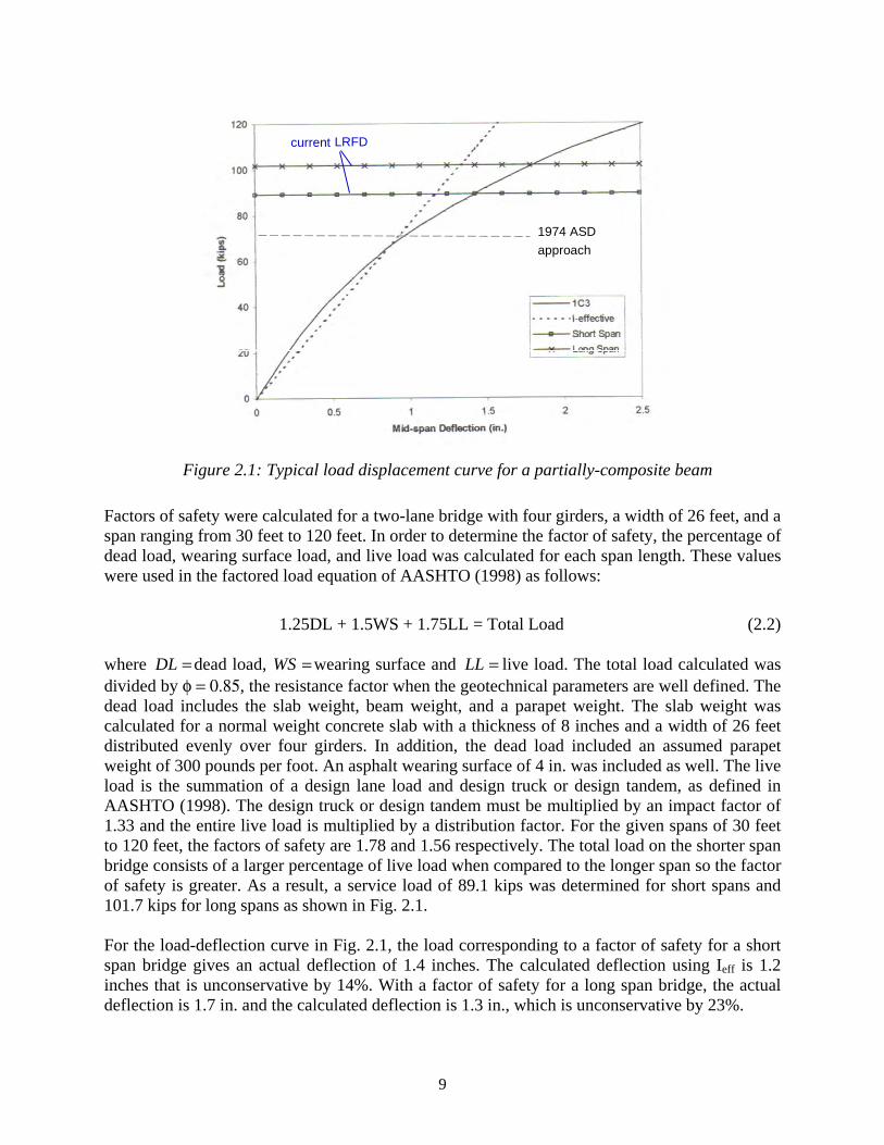
Figure 2.1 shows the initial portion of the load-deflection curve for specimen 1C3 from the research by Grant et al. (1977). The maximum load for 1C3 was 159 kips. The test response becomes non-linear at a load of approximately 30 kips. A predicted elastic load-deflection curve (short dash line) using Ieff from Eq. 2.1 is also plotted. Detail calculations for Ieff for specimen 1C3 are given in Methvin 2004. For this specimen, the elastic deflection prediction is very close to the actual deflection at the 1974 service load (long dash line), as expected, as Eq. 2.1 was fit to that data point. The ASD factor of safety used to determine the service load is larger than the factor of safety provided with the current AASHTO design provisions. In order to evaluate the suitability of Eq 2.1 for use with AASHTO, the maximum test load was divided by the AASHTO factor of safety.
9
Figure 2.1: Typical load displacement curve for a partially-composite beam
Factors of safety were calculated for a two-lane bridge with four girders, a width of 26 feet, and a span ranging from 30 feet to 120 feet. In order to determine the factor of safety, the percentage of dead load, wearing surface load, and live load was calculated for each span length. These values were used in the factored load equation of AASHTO (1998) as follows:
1.25DL + 1.5WS + 1.75LL = Total Load (2.2) where =DL dead load, =WS wearing surface and =LL live load. The total load calculated was divided by φ = 0.85, the resistance factor when the geotechnical parameters are well defined. The dead load includes the slab weight, beam weight, and a parapet weight. The slab weight was calculated for a normal weight concrete slab with a thickness of 8 inches and a width of 26 feet distributed evenly over four girders. In addition, the dead load included an assumed parapet weight of 300 pounds per foot. An asphalt wearing surface of 4 in. was included as well. The live load is the summation of a design lane load and design truck or design tandem, as defined in AASHTO (1998). The design truck or design tandem must be multiplied by an impact factor of 1.33 and the entire live load is multiplied by a distribution factor. For the given spans of 30 feet to 120 feet, the factors of safety are 1.78 and 1.56 respectively. The total load on the shorter span bridge consists of a larger percentage of live load when compared to the longer span so the factor of safety is greater. As a result, a service load of 89.1 kips was determined for short spans and 101.7 kips for long spans as shown in Fig. 2.1. For the load-deflection curve in Fig. 2.1, the load corresponding to a factor of safety for a short span bridge gives an actual deflection of 1.4 inches. The calculated deflection using Ieff is 1.2 inches that is unconservative by 14%. With a factor of safety for a long span bridge, the actual deflection is 1.7 in. and the calculated deflection is 1.3 in., which is unconservative by 23%.
1974 ASD approach
current LRFD
1974 ASD approach
current LRFD
10
Grant et al. (1977) included six load-deflection curves for different beams with varying degrees of partial composite action. The service loads based on AASHTO (1998) were determined for all the tests as described in Methvin 2004. The actual deflections were compared to the computed deflections based on Ieff from Eq. 2.1 for the safety factors for short and long spans. Nearly all of the calculated deflections were unconservative. The percentage of difference between the actual deflection and the calculated deflection was averaged for the six load-deflection curves and given in Table 2.1 for Ieff. The negative numbers indicate that on average the calculated deflections are unconservative. The range of all the data is shown in parenthesis.
Table 2.1: Average (range) % of variation between actual and calculated deflection
Modified Ic Short Span Long span
Ieff (Eq. 2.1) -12% (+5 to -23%)
-19% (-4 to -30%)
0.80 Ieff +15%
(+32 to -4%) +12%
(+21 to -13%)
0.75 Ieff +21%
(+2 to +40%) +13%
(+28 to -7%)
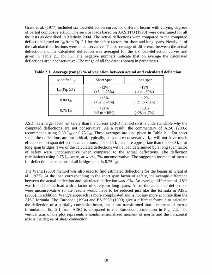
ASD has a larger factor of safety than the current LRFD method so it is understandable why the computed deflections are not conservative. As a result, the commentary of AISC (2005) recommends using 0.80 Ieff or 0.75 Ieff. These averages are also given in Table 2.1. For short spans the deflections are not critical, typically, so a more conservative Ieff will not have much effect on short span deflection calculations. The 0.75 Ieff is more appropriate than the 0.80 Ieff for long span bridges. Two of the calculated deflections with a load determined by a long span factor of safety were unconservative when compared to the actual deflections. The deflection calculations using 0.75 Ieff were, at worst, 7% unconservative. The suggested moment of inertia for deflection calculations of all bridge spans is 0.75 Ieff. The Wang (2003) method was also used to find estimated deflections for the beams in Grant et al. (1977). At the load corresponding to the short span factor of safety, the average difference between the actual deflection and calculated deflection was -9%. An average difference of -18% was found for the load with a factor of safety for long spans. All of the calculated deflections were unconservative so the results would have to be reduced just like the formula in AISC (2005). In addition, Wang’s approach is more complicated and is not any more accurate than the AISC formula. The Eurocode (1994) and BS 5950 (1990) give a different formula to calculate the deflection of a partially composite beam, but it can transformed into a moment of inertia formulation. Eq. 2.1 from AISC is compared to the Eurocode formulation in Fig. 2.2. The vertical axis of the plot represents a nondimensionalized moment of inertia and the horizontal axis is the degree of shear connection.
11
Figure 2.2: Comparisons of effective moments of inertia
AISC (2001) allows a minimum shear connection of 25% while the Eurocode (1994) suggests using a shear connection greater than 40%. From Figure 2.3, for a shear connection greater than 45%, the Eurocode equation will give a slightly smaller moment of inertia, or a more conservative moment of inertia. However, the differences are minimal.
2.3 Recommendations for Predicting Deflections Predicting an accurate deflection is difficult, but simple methods can be used to estimate a deflection within 15–20%. Simplified methods are adequate because deflection limitations are guidelines from past experience and a member can easily meet strength requirements while exceeding the deflection limitation. Research has shown that beams designed for full composite action will have some slip between the concrete slab and steel beam. A deflection can be calculated using the transformed moment of inertia; however, this transformed moment of inertia should be reduced by 15% in order to be conservative. The effective moment of inertia equation in AISC (2001) can be used to accurately calculate the deflection of a partial composite beam. For all bridge spans, the AISC equation should be reduced by 25% in order to get accurate and conservative deflection calculations The following recommendations will give conservative predictions for service load deflections: for full composite design use 0.85 Ic, and 0.75 Ieff for partial composite design. Theoretical approaches, which include the effects of slip, are just as accurate as and more complicated to use than the simplified methods.
Ieff –Is Ic-Is
h
hV
V′

12
13
Chapter 3. Minimum and Maximum Spacing of Shear Connectors
3.1 Stud Spacing Limits in Design Specifications In AASHTO (1998), the maximum permitted center-to center (c-c) spacing of shear connectors is 24 in. The minimum spacing requirement in the longitudinal direction is greater than or equal to 6d where d is diameter of the shear stud. The minimum spacing in the direction transverse to the longitudinal axis is greater than or equal to 4d. The AISC steel building specification (AISC 2005) has the same minimum spacing requirements as AASHTO. The maximum spacing requirement in AISC is 36 in. or eight times the slab thickness. In Eurocode 4, the minimum c-c stud spacing requirements of 5d in the longitudinal direction and 2.5d in the transverse direction are smaller than the requirements in U.S. practice stated earlier. The maximum longitudinal spacing is six times the slab thickness but not more than 32 inches.
3.2 Basis for Maximum Spacing AASHTO’s current maximum spacing requirement of 24 inches first appeared in the fourth edition of AASHTO Standard Specification for Highway Bridges (1944). During this time period, composite design research for the Public Roads Administration was being conducted at the University of Illinois (Newmark and Seiss 1943). They conducted ¼ scale model tests on composite bridges and recommended that the maximum spacing be limited to three or four times the depth of the slab because of potential separation between the slab and the steel beams. The prototype bridge had a 7 in. slab so the 24 inch maximum spacing requirement corresponds to 3.5 times the slab thickness as used in the model studies. Full size T-beam tests with a 6 in. deep slab were reported by Viest et al., (1952); they evaluated the maximum spacing issue by measuring the separation between the slab and the steel beam. Two composite beams were similar except for stud spacing: 18 inches in one and 36 inches in the other. The test with a spacing of three times the slab thickness showed no separation. The test with a spacing of six times the slab thickness had a separation of 0.003 in. at first yield of the composite T-beam and then rapidly increased to 0.042 in. at ultimate. The authors state:
“although the separation between the two connectors was probably not large enough to have any detrimental effect on the behavior of the T-beam, it might allow moisture to enter under the slab and thus result in corrosion of the upper flange.”
For building design, a composite beam is not exposed to the elements, so corrosion effects are not as much of a problem as with bridges. The first maximum spacing provision appeared in the 1974 Supplement to the AISC Specification and was eight times the slab thickness. Viest et al. (1997) suggested a maximum spacing of eight times the slab thickness but not more than 36 inches, which was adopted in the 2005 AISC Specification.
14
Bridges have been constructed in Switzerland using the slip-decking construction method (ASCE, 1974) with spacing of three to four feet between clusters of studs.
3.3 Basis for Minimum Spacing Minimum c-c spacing requirements first appeared in design specifications in 1971, with a spacing of 3d in all directions found in Supplement No. 2 of the 1969 AISC specification. The minimum spacing was changed to the current values of 4d (transverse) and 6d (longitudinal) a few years later in Supplement No. 3, issued in 1974. AISC refers to Ollgaard et al. (1971) as the basis for the minimum spacing; however, the spacing of the shear studs was not a specific factor in that research. The explanation for the minimum spacing requirements was provided by Milek, AISC Vice President of Engineering, in 1979 correspondence copied to the AISC Committee on Specifications as follows:
“The provisions for stud spacing contained in the AISC Specification are based upon observation of the fracture cones in the concrete around the studs of beams tested to their ultimate strength. After the beams (sic) had been tested to its ultimate load, but not totally destroyed by continued loading, the specimen was sawed longitudinally through the center line of the studs. It was observed that the concrete was fractured in an asymmetric cone that extended four diameters in front of the stud and two diameters behind the studs at the surface of the steel beam and with the apex at the head of the stud. The studs were four diameters high because it had been observed in previous tests that studs more than four diameters high failed by shear through the stud rather than by crushing of the concrete. On the basis of this limited information and the reasoning that interference between fractured cones around adjacent studs should be avoided, six diameter longitudinal and four diameter lateral spacing rules were proposed and adopted. The Committee did not consider the question of minimum spacing along a diagonal line. To the basis of my knowledge no test program has been conducted in which minimum spacing between clustered studs have been the principal variable.”
In AASHTO, minimum stud spacing provisions did not appear until the 1990 Interim Specification adopted a minimum spacing of 4d in all directions. The current values first appeared in the 1994 AASHTO LRFD Specification. Johnson (1994) states that the required minimum spacings of shear connectors given in the Eurocode are to “enable concrete to be properly compacted, and to avoid local overstress of the slab.” The clear spacing limits in ACI 318-02 for rebar are also required to allow for proper concrete compaction. The limits in ACI 318-02 are the larger of the bar diameter, one inch, or 1.33 times the diameter of the coarse aggregate. These minimum clear spacing limits are smaller than the minimum center-to-center spacing limits for shear connectors. For example, a 7/8-inch diameter stud has a head diameter of 1-3/8 inches, so a one-inch minimum spacing requirement between the heads would require a minimum c-c stud spacing of 2-3/8 inches, which is a c-c spacing of 2.7d. This is close to the Eurocode transverse limit of 2.5d. The need to accommodate stud welding equipment must also be considered. A 4d spacing is recommended for convenience of the welding equipment in Canadian practice (Chien and Ritchie, 1984).
15
3.4 Summary of Shear Connector Spacing and Recommendations There is not much research on the effects of the minimum spacing and if the AASHTO requirements were to be reduced, then laboratory testing is recommended. A series of push-out tests should be conducted with studs spaced at 3d, which is close to the ACI clear limit, and with studs placed at 6d, the current AASHTO limit. The maximum spacing requirement in AASHTO is 24 inches. There is experimental research to support this requirement that the 24 inches will prevent uplift and reduce the chances of corrosion problems. However, there is no evidence to prove that non-composite bridges experience excessive corrosion. The AASHTO should have a limit related to slab thickness as in all other specifications.

16
17
Chapter 4. Fatigue Behavior of Shear Studs
4.1 Introduction According to the design requirements given by AASHTO (1998), the shear connection for the composite beam must meet both strength requirements and fatigue requirements. The fatigue requirements in AASHTO are based on the Sr (shear stress range) -N (number of cycles) relationship developed by Slutter and Fisher, 1966, from push-out tests and supported by the composite beam tests by Toprac, 1965. The more recent investigations on the fatigue of shear connectors have provided additional Sr-N relationships, studied the effects of low-cycle fatigue, examined the effects of cyclic loading on the static strength of a shear stud, and evaluated the use of larger shear studs for composite action. In this chapter the development of the AASHTO fatigue provisions for shear connectors is presented and AASHTO provisions compared with other design specifications. Recent research on studs subjected to cyclic loading is critiqued.
4.2 AASHTO LRFD Fatigue Design of Shear Connectors
4.2.1 AASHTO Provisions The fatigue design of shear connectors is based on the elastic shear flow between the slab and girder, as well as the estimated number of cycles for the required design life. The shear flow at the interface is calculated as:
c
srf I
QVV = (4.1)
where Vf = shear flow (kip/in.), Vsr = shear force range (kips) and Q = first moment of the area of concrete deck about the neutral axis of the composite section (in3). Vsr is calculated using the AASHTO fatigue truck and shear distribution factors for the girders. The fatigue resistance of one shear stud, Zr, (kips) is:
25.5 2
2 ddZr ≥= α (4.2)
and NLog28.45.34 −=α (4.3)
where =d diameter of shear stud (inches) and =N estimated number of cycles for the design life. α is based upon the Slutter and Fisher (1966) relationship between the stud shear stress range and the fatigue life of a shear connector presented in the next section. The 5.5d2/2 term is an endurance limit corresponding to a stud shear stress of 3.5 ksi. The spacing or pitch, p, (inches) of the connectors is given by:
18
f
r
VnZp ≤ (4.4)
where n = number of studs at the location of Vsr
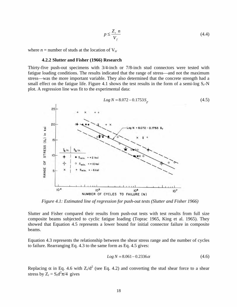
4.2.2 Slutter and Fisher (1966) Research Thirty-five push-out specimens with 3/4-inch or 7/8-inch stud connectors were tested with fatigue loading conditions. The results indicated that the range of stress—and not the maximum stress—was the more important variable. They also determined that the concrete strength had a small effect on the fatigue life. Figure 4.1 shows the test results in the form of a semi-log Sr-N plot. A regression line was fit to the experimental data:
rSNLog 1753.0072.8 −= (4.5)
Figure 4.1: Estimated line of regression for push-out tests (Slutter and Fisher 1966)
Slutter and Fisher compared their results from push-out tests with test results from full size composite beams subjected to cyclic fatigue loading (Toprac 1965, King et al. 1965). They showed that Equation 4.5 represents a lower bound for initial connector failure in composite beams. Equation 4.3 represents the relationship between the shear stress range and the number of cycles to failure. Rearranging Eq. 4.3 to the same form as Eq. 4.5 gives:
α2336.0061.8 −=NLog (4.6)
Replacing α in Eq. 4.6 with Zr/d2 (see Eq. 4.2) and converting the stud shear force to a shear stress by Zr = Srd2π/4 gives
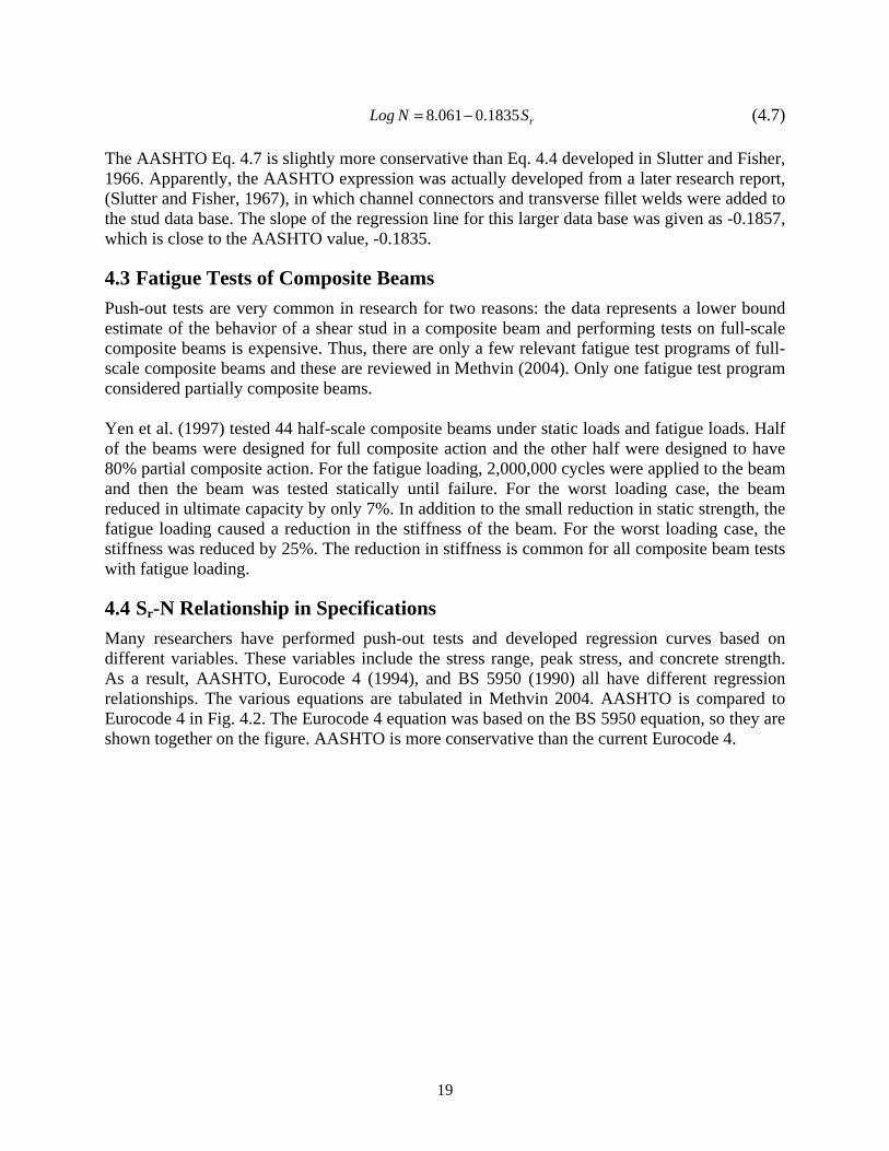
19
rSNLog 1835.0061.8 −= (4.7) The AASHTO Eq. 4.7 is slightly more conservative than Eq. 4.4 developed in Slutter and Fisher, 1966. Apparently, the AASHTO expression was actually developed from a later research report, (Slutter and Fisher, 1967), in which channel connectors and transverse fillet welds were added to the stud data base. The slope of the regression line for this larger data base was given as -0.1857, which is close to the AASHTO value, -0.1835.
4.3 Fatigue Tests of Composite Beams Push-out tests are very common in research for two reasons: the data represents a lower bound estimate of the behavior of a shear stud in a composite beam and performing tests on full-scale composite beams is expensive. Thus, there are only a few relevant fatigue test programs of full-scale composite beams and these are reviewed in Methvin (2004). Only one fatigue test program considered partially composite beams. Yen et al. (1997) tested 44 half-scale composite beams under static loads and fatigue loads. Half of the beams were designed for full composite action and the other half were designed to have 80% partial composite action. For the fatigue loading, 2,000,000 cycles were applied to the beam and then the beam was tested statically until failure. For the worst loading case, the beam reduced in ultimate capacity by only 7%. In addition to the small reduction in static strength, the fatigue loading caused a reduction in the stiffness of the beam. For the worst loading case, the stiffness was reduced by 25%. The reduction in stiffness is common for all composite beam tests with fatigue loading.
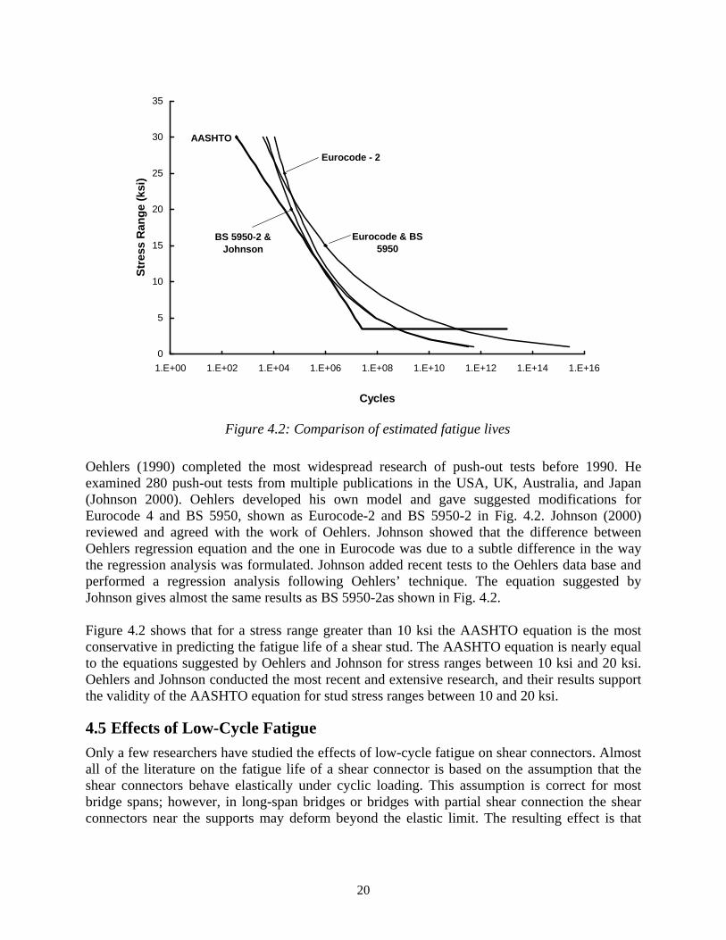
4.4 Sr-N Relationship in Specifications Many researchers have performed push-out tests and developed regression curves based on different variables. These variables include the stress range, peak stress, and concrete strength. As a result, AASHTO, Eurocode 4 (1994), and BS 5950 (1990) all have different regression relationships. The various equations are tabulated in Methvin 2004. AASHTO is compared to Eurocode 4 in Fig. 4.2. The Eurocode 4 equation was based on the BS 5950 equation, so they are shown together on the figure. AASHTO is more conservative than the current Eurocode 4.
20
AASHTO
Eurocode & BS 5950
Eurocode - 2
BS 5950-2 & Johnson
0
5
10
15
20
25
30
35
1.E+00 1.E+02 1.E+04 1.E+06 1.E+08 1.E+10 1.E+12 1.E+14 1.E+16
Cycles
Stre
ss R
ange
(ksi
)
Figure 4.2: Comparison of estimated fatigue lives
Oehlers (1990) completed the most widespread research of push-out tests before 1990. He examined 280 push-out tests from multiple publications in the USA, UK, Australia, and Japan (Johnson 2000). Oehlers developed his own model and gave suggested modifications for Eurocode 4 and BS 5950, shown as Eurocode-2 and BS 5950-2 in Fig. 4.2. Johnson (2000) reviewed and agreed with the work of Oehlers. Johnson showed that the difference between Oehlers regression equation and the one in Eurocode was due to a subtle difference in the way the regression analysis was formulated. Johnson added recent tests to the Oehlers data base and performed a regression analysis following Oehlers’ technique. The equation suggested by Johnson gives almost the same results as BS 5950-2as shown in Fig. 4.2. Figure 4.2 shows that for a stress range greater than 10 ksi the AASHTO equation is the most conservative in predicting the fatigue life of a shear stud. The AASHTO equation is nearly equal to the equations suggested by Oehlers and Johnson for stress ranges between 10 ksi and 20 ksi. Oehlers and Johnson conducted the most recent and extensive research, and their results support the validity of the AASHTO equation for stud stress ranges between 10 and 20 ksi.
4.5 Effects of Low-Cycle Fatigue Only a few researchers have studied the effects of low-cycle fatigue on shear connectors. Almost all of the literature on the fatigue life of a shear connector is based on the assumption that the shear connectors behave elastically under cyclic loading. This assumption is correct for most bridge spans; however, in long-span bridges or bridges with partial shear connection the shear connectors near the supports may deform beyond the elastic limit. The resulting effect is that
21
these connectors will fail at a lower number of cycles than predicted using the elastic assumption. Gattesco et al. (1997) determined the fatigue resistance of a shear stud subjected to a predetermined slip history from a simple beam subjected to a uniformly distributed load. When the maximum slip was greater than 1 mm, the fatigue resistance was less than 104 cycles. For slips greater than 1 mm the fatigue life decreased rapidly. In addition, the slope of the load-slip curve decreased with each cycle, which is an indication of a reduction in stiffness of the stud due to crack propagation. Although there is not a lot of research on the effects of low-cycle fatigue, the results indicate that shear studs exposed to this type of loading will be affected negatively. It is important for long-span composite beams and partially composite beams that the effects of low-cycle fatigue be researched further.
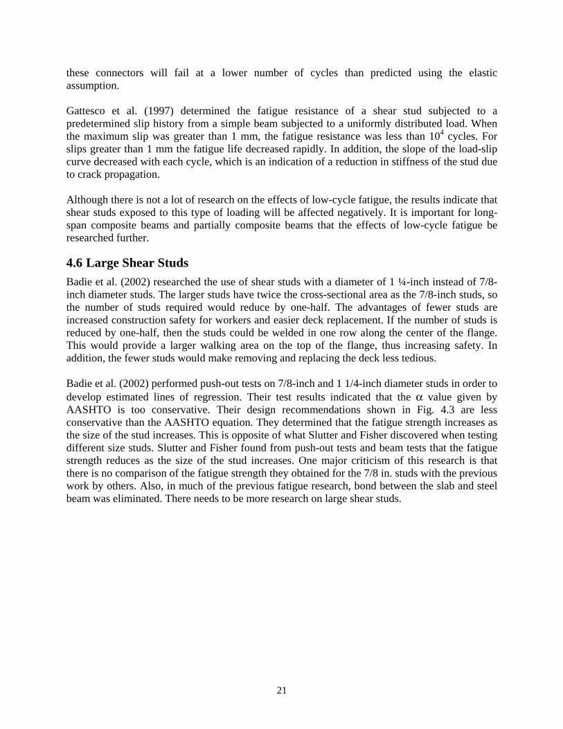
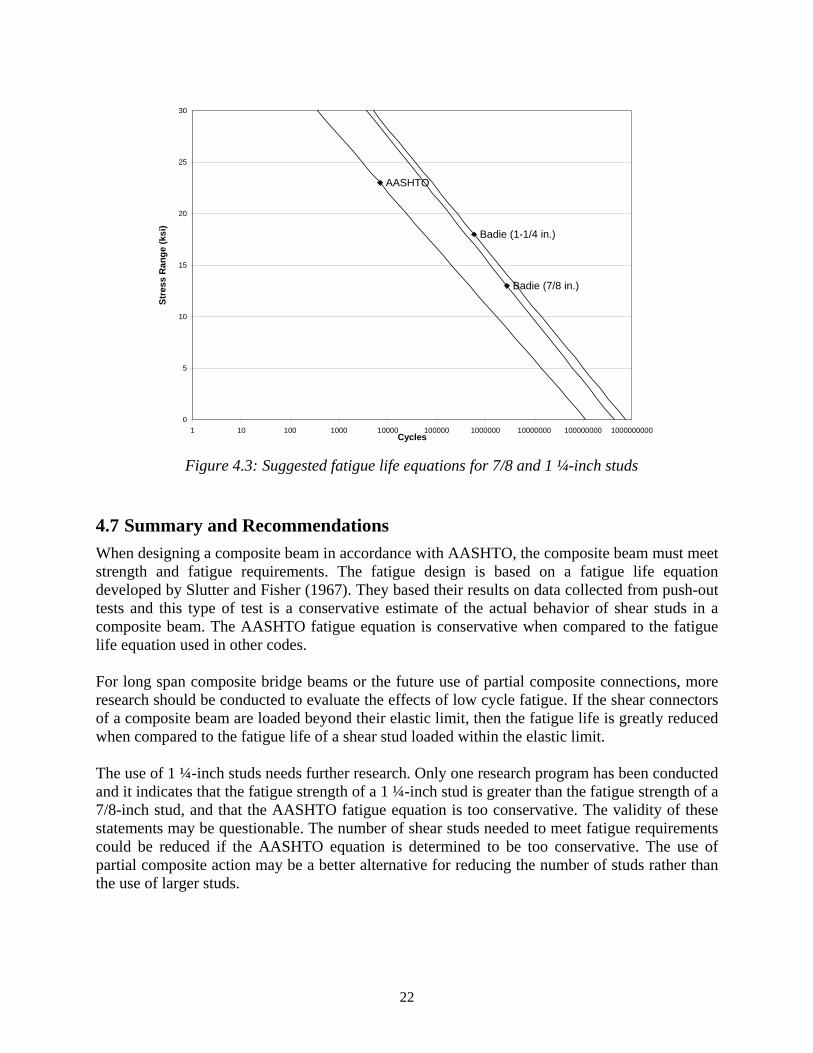
4.6 Large Shear Studs Badie et al. (2002) researched the use of shear studs with a diameter of 1 ¼-inch instead of 7/8-inch diameter studs. The larger studs have twice the cross-sectional area as the 7/8-inch studs, so the number of studs required would reduce by one-half. The advantages of fewer studs are increased construction safety for workers and easier deck replacement. If the number of studs is reduced by one-half, then the studs could be welded in one row along the center of the flange. This would provide a larger walking area on the top of the flange, thus increasing safety. In addition, the fewer studs would make removing and replacing the deck less tedious. Badie et al. (2002) performed push-out tests on 7/8-inch and 1 1/4-inch diameter studs in order to develop estimated lines of regression. Their test results indicated that the α value given by AASHTO is too conservative. Their design recommendations shown in Fig. 4.3 are less conservative than the AASHTO equation. They determined that the fatigue strength increases as the size of the stud increases. This is opposite of what Slutter and Fisher discovered when testing different size studs. Slutter and Fisher found from push-out tests and beam tests that the fatigue strength reduces as the size of the stud increases. One major criticism of this research is that there is no comparison of the fatigue strength they obtained for the 7/8 in. studs with the previous work by others. Also, in much of the previous fatigue research, bond between the slab and steel beam was eliminated. There needs to be more research on large shear studs.
22
AASHTO
Badie (1-1/4 in.)
Badie (7/8 in.)
0
5
10
15
20
25
30
1 10 100 1000 10000 100000 1000000 10000000 100000000 1000000000Cycles
Stre
ss R
ange
(ksi
)
Figure 4.3: Suggested fatigue life equations for 7/8 and 1 ¼-inch studs
4.7 Summary and Recommendations When designing a composite beam in accordance with AASHTO, the composite beam must meet strength and fatigue requirements. The fatigue design is based on a fatigue life equation developed by Slutter and Fisher (1967). They based their results on data collected from push-out tests and this type of test is a conservative estimate of the actual behavior of shear studs in a composite beam. The AASHTO fatigue equation is conservative when compared to the fatigue life equation used in other codes. For long span composite bridge beams or the future use of partial composite connections, more research should be conducted to evaluate the effects of low cycle fatigue. If the shear connectors of a composite beam are loaded beyond their elastic limit, then the fatigue life is greatly reduced when compared to the fatigue life of a shear stud loaded within the elastic limit. The use of 1 ¼-inch studs needs further research. Only one research program has been conducted and it indicates that the fatigue strength of a 1 ¼-inch stud is greater than the fatigue strength of a 7/8-inch stud, and that the AASHTO fatigue equation is too conservative. The validity of these statements may be questionable. The number of shear studs needed to meet fatigue requirements could be reduced if the AASHTO equation is determined to be too conservative. The use of partial composite action may be a better alternative for reducing the number of studs rather than the use of larger studs.
23
Chapter 5. Summary of Recommendations for Composite Steel Bridge Beams
The deflection of a composite steel bridge beam can be conservatively estimated with simplified methods. For a beam designed to have full composite action, the deflection can be calculated using a transformed moment of inertia. It is recommended that this transformed moment of inertia should be reduced by 15% in order to calculate a conservative estimated deflection. The effective moment of inertia given in AISC (2001) can be used to calculate the deflection of a partial composite beam. This effective moment of inertia should be reduced by 25% for short span bridges and long span bridges. Following this recommendation is a conservative estimate of the service load deflection.
It is recommended that partial composite be considered for bridges. It is not a new concept. It is recommended that the number studs not be less than 50% of the full composite value. If partial composite action is used on bridges, then the service load deflection of a partially composite beam can be accurately predicted with the suggested effective moment of inertia method. The maximum spacing of shear connectors of 24 inches needs further research. This limit will prevent uplift of the slab and reduce the chances of moisture getting between the slab and steel beam. Moisture between the slab and the steel beam could cause corrosion problems. However, there is no record of non-composite bridges with excessive corrosion. The minimum shear connector spacing requirements should remain the same unless experiments are performed on push-out specimens or composite beams with a smaller shear stud spacing. If the minimum spacing requirements are reduced, then the requirements given by ACI 318-02 should be considered. The minimum spacing requirements are given in ACI 318-02 in order to allow for the proper compaction of the concrete. In order to allow for enough space for proper compaction between the shear studs, the minimum spacing requirement must be between the heads of the shear studs. For a 7/8-inch diameter stud, the spacing requirement based on ACI 318-02 would be about 3d. Tests should be conducted at this spacing. The fatigue requirements in AASHTO are based on the research by Slutter and Fisher (1966). Current research indicates that no changes are needed in AASHTO provisions. Further research on low-cycle fatigue and large shear studs is recommended.

24
25
References
American Association of State Highway and Transportation Officials (AASHTO). (1998). “Load and Resistance Factor Design Specification for Highway Bridges.” Washington, D.C.
American Concrete Institute (ACI) (2002), Building Code Requirements for Structural Concrete, ACI 318-02, Detroit, MI.
American Institute of Steel Construction (AISC). (2005). Specification for Structural Steel Buildings, Chicago, IL.
American Society of Civil Engineers (ASCE), (1974). “Composite steel-concrete construction,” Journal of Structural Engineering, ASCE, Vol. 100, No. ST5, pp 1085-1139.
Badie, Sameh S., et al. Large Shear Studs for Composite Action in Steel Bridge Girders. Journal of Bridge Engineering. May/June 2002.
BS 5950. (1990). Structural use of steelwork in buildings, Part 3: Section 3.1: Code of practice for design of simple and continuous composite beams. British Standards Institution, London, U.K.
Chien, E. and Ritchie, J. (1984). Design and Construction of Composite Floor Systems, Canadian Institute of Steel Construction, 336 p.
Eurocode 4. (1994). Design of composite steel and concrete structures. Part 1: General rules and rules for buildings, Part 2: Bridges. ENV 1994-2, CEN, Brussels
Gattesco, N., Giuriani, E., and Gubana, A. (1997). “Low-cycle fatigue test on stud shear connectors.” J. of Structural Engineering, Vol. 123, No.2, 145–150.
Grant, J. A., Fisher, J. W., and Slutter, R. G. (1977). “Composite Beams with Formed Steel Deck,” Engineering Journal, AISC, Vol. 14, No. 1: 24-43.
Johnson, R. P. (1994). Composite Structures of Steel and Concrete, Vol. 1, 2nd Ed., Blackwell Scientific Publications, Oxford
Johnson, R. P. (2000). “Resistance of stud shear connectors to fatigue.” Journal of Constructional Steel Research, Vol.56, pp 101–116.
King, D., Slutter, R. and Driscoll, G. (1965). “Fatigue strength of 1/2-inch diameter stud shear connectors.” Highway Research Record 103, pp 78-106.
McGarraugh, J. B. and Baldwin, J. W. (1971). “Lightweight Concrete-On-Steel Composite Beams.” Engineering Journal, AISC, Vol. 8, No. 3.
26
Methvin, E. (2004). Recommendations for Stud Design in Composite Steel Bridge Beams, MS Thesis, U. of Texas at Austin, Dec., 69 p,
Newmark, N. and Seiss, C. (1943). “Design of slab and stringer bridges,” Public Roads, Vol. 23, No. 7, pp 157-164
Nie, Jianguo and Cai, C. (2003). “Steel-concrete composite beams considering shear slip effects.” Journal of Structural Engineering, ASCE, Vol. 129, No. 4, pp 495-506.
Oehlers, D. (1990).Methods of estimating the fatigue endurances of stud shear connectors. Proc. P-145/90, Int. Assoc. for Bridge and Struct. Engrgs., Zurich, pp 65-84.
Ollgaard, J., Slutter, R. and Fisher, J. (1971). “Shear strength of stud connectors in lightweight and normal-weight concrete.” Engineering Journal, AISC, Vol. 8, No. 2, pp 55-64.
Salmon, C. and Johnson, J. (1996). Steel Structures: Design and Behavior, 4th Ed., Prentice-Hall, New Jersey.
Slutter, R. and Driscoll, G. (1965). “Flexural strength of steel and concrete composite beams.” J.of the Structural Division, ASCE, Vol. 91, No. ST2, pp 71-99.
Slutter, R. and Fisher, J. (1966). “Fatigue strength of shear connectors.” Highway Research Record No.147, Highway Research Board, pp 65-88.
Slutter, R. and Fisher, J. (1967). “Fatigue strength of shear connectors.” Steel Research for Construction Bulletin No. 5, American Iron and Steel Institute, Oct., 38 p.
Toprac, A. (1965). “Fatigue strength of 3/4-inch stud shear connectors.” Highway Research Record No. 103, Highway Research Board, pp 53-77.
Viest, I., Siess, C., Appleton, J. and Newmark, N. (1952). “Studies of slab and beam highway bridges, part IV,” U. of Illinois Engineering Experiment Station, Bulletin No. 405, 155 p.
Viest, I., Colaco, J., Furlong, R., Griffis, L., Leon, R. and Wyllie, L. (1997). Composite Construction: Design for Buildings. McGraw Hill, New York.
Wang, Y. (1998). “Deflection of steel-concrete composite beams with partial shear interaction.” J. of Structural Engineering, ASCE, Vol.124, No.10, 1159-1165.
Yen, J., Lin, Y. and Lai, M. (1997). “Composite beams subjected to static and fatigue loads.” Journal of Structural Engineering, ASCE, Vol. 123, No.6, pp 765-771.