Embed Size (px)
Citation preview
FFI-rapport 2011/00537
Design of an initial LLC Data Protocol for the NBWF Simulator
Tore J. Berg
Norwegian Defence Research Establishment (FFI)
21 March 2012
2 FFI-rapport 2011/00537
FFI-rapport 2011/00537
1175
P: ISBN 978-82-464-2078-3
E: ISBN 978-82-464-2079-0
Keywords
Modellering og simulering
Datanett
Radionett
Trådløse nett
Approved by
Torunn Øvreås Project Manager
Anders Eggen Director
FFI-rapport 2011/00537 3
English summary
NATO has an ongoing activity with the objective to develop a narrowband waveform (NBWF)
standard. This is a single-channel mobile ad-hoc network (MANET) which shall serve voice
traffic and data traffic over a 25 kHz radio channel. We have earlier contributed to the NATO
NBWF activity by delivering a design of an initial NBWF network simulator where the Logical
Link Control (LLC) protocol was not optimised for NBWF. This document specifies a protocol
for IP traffic and a design better suited for the NBWF radio node. This report includes a few
simulation experiments for testing the implementation and the correctness of the protocol.

4 FFI-rapport 2011/00537
Sammendrag
Nato har en pågående aktivitet for standardisering av en smalbånds bølgeform for bruk i VHF
området. FFI har en modellerings- og simuleringsaktivitet som skal bidra til NATO aktiviteten
ved å vurdere alternative protokollfunksjoner for betjening av tale og datatrafikk i distribuerte
mobile nett. Dette dokumentet spesifiserer en robust linkprotokoll for transport av datapakker
over en upålitelig kanal. Protokollen implementeres i en simulator. Rapporten presenterer noen
simuleringseksperimenter med det formål å teste korrekthet av protokoll og implementasjon.
FFI-rapport 2011/00537 5
Contents
1 Introduction 7
1.1 Terminology 8
2 Overview of the Protocol 10
2.1 Services provided by the LLC layer 12
2.2 Services assumed from the MAC layer 13
3 Elements of Procedure 18
3.1 Connection Establishment 18
3.2 LLC SDU Transfer 19
3.3 Normal Release 19
3.4 LLC SDU Lifetime Control 19
3.5 Duplicate Filtering 19
3.6 Discard LLC SDU 20
3.7 Segmentation and Reassembly of LLC SDUs 20
3.8 Segmentation and Reassembly of LLC DT PDUs 22
3.9 Lifetime Control 22
3.10 Acknowledgement of DT PDUs 22
3.11 The internal buffer structure 25
4 Validation 26
4.1 Estimators 29
4.2 Experiments with ARQ disabled 30
4.3 Experiments with ARQ enabled 35
4.4 Communication over noisy radio channels 36
5 Conclusions and Remarks 40
References 41
Terms and Acronyms 42

6 FFI-rapport 2011/00537
FFI-rapport 2011/00537 7
1 Introduction
The NATO NC3B CaP/1 LOS CaT has an ongoing activity with the objective to develop a
narrowband waveform (NBWF) standard [1]. This is a single-channel mobile ad-hoc network
(MANET), which shall serve voice and data traffic over a 25 kHz radio channel.
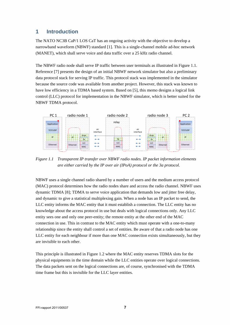
The NBWF radio node shall serve IP traffic between user terminals as illustrated in Figure 1.1.
Reference [7] presents the design of an initial NBWF network simulator but also a preliminary
data protocol stack for serving IP traffic. This protocol stack was implemented in the simulator
because the source code was available from another project. However, this stack was known to
have low efficiency in a TDMA based system. Based on [5], this memo designs a logical link
control (LLC) protocol for implementation in the NBWF simulator, which is better suited for the
NBWF TDMA protocol.
Application
TCP/UDP
IP
Ethernet
PC 1
IPoA
LLC
3a
MAC
IP
Ethernet
radio node 1
IPoA
LLC
3a
MAC
IP
Ethernet
radio node 3
Application
TCP/UDP
IP
Ethernet
PC 2
LLC
3a
MAC
radio node 2
relay
airinterface
airinterface
Figure 1.1 Transparent IP transfer over NBWF radio nodes. IP packet information elements
are either carried by the IP over air (IPoA) protocol or the 3a protocol.
NBWF uses a single channel radio shared by a number of users and the medium access protocol
(MAC) protocol determines how the radio nodes share and access the radio channel. NBWF uses
dynamic TDMA [8]; TDMA to serve voice application that demands low and jitter free delay,
and dynamic to give a statistical multiplexing gain. When a node has an IP packet to send, the
LLC entity informs the MAC entity that it must establish a connection. The LLC entity has no
knowledge about the access protocol in use but deals with logical connections only. Any LLC
entity sees one and only one peer-entity; the remote entity at the other end of the MAC
connection in use. This in contrast to the MAC entity which must operate with a one-to-many
relationship since the entity shall control a set of entities. Be aware of that a radio node has one
LLC entity for each neighbour if more than one MAC connection exists simultaneously, but they
are invisible to each other.
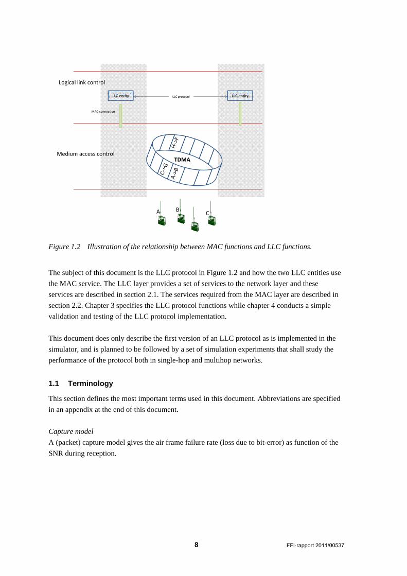
This principle is illustrated in Figure 1.2 where the MAC entity reserves TDMA slots for the
physical equipments in the time domain while the LLC entities operate over logical connections.
The data packets sent on the logical connections are, of course, synchronised with the TDMA
time frame but this is invisible for the LLC layer entities.
8 FFI-rapport 2011/00537
A BC
Medium access control
Logical link control
LLC‐entity LLC‐entity
MAC‐connection
TDMA
LLC protocol
Figure 1.2 Illustration of the relationship between MAC functions and LLC functions.
The subject of this document is the LLC protocol in Figure 1.2 and how the two LLC entities use
the MAC service. The LLC layer provides a set of services to the network layer and these
services are described in section 2.1. The services required from the MAC layer are described in
section 2.2. Chapter 3 specifies the LLC protocol functions while chapter 4 conducts a simple
validation and testing of the LLC protocol implementation.
This document does only describe the first version of an LLC protocol as is implemented in the
simulator, and is planned to be followed by a set of simulation experiments that shall study the
performance of the protocol both in single-hop and multihop networks.
1.1 Terminology
This section defines the most important terms used in this document. Abbreviations are specified
in an appendix at the end of this document.
Capture model
A (packet) capture model gives the air frame failure rate (loss due to bit-error) as function of the
SNR during reception.
FFI-rapport 2011/00537 9
Zero-capture model
The preamble of an incoming air frame is handled according the normal NBWF procedure [9]1.
When the receiver is locked onto an air frame, any overlapping transmission(s) introduce bit-
errors in the payload.
Perfect capture model
The preamble of an incoming air frame is handled according to the normal NBWF procedure [9]
but the preamble detection threshold is improved by 10 dB. When the receiver is locked onto an
air frame, this air frame is always correctly received regardless of the SNR condition of the radio
channel.
NBWF capture model
This is the normal operating mode as described in [9].
The near-far problem
A receiver is locked to a weak signal from a distant node when a node in the vicinity starts to emit
a high energy signal. The stronger signal overrides the weaker signal.
Sink-node
An end-destination for an IP traffic stream.
Entry-node
A radio node which is the source node for an IP traffic stream (fresh input traffic) from an IP
client.
Edge-node
A node taking the role as a sink-node and/or entry-node.
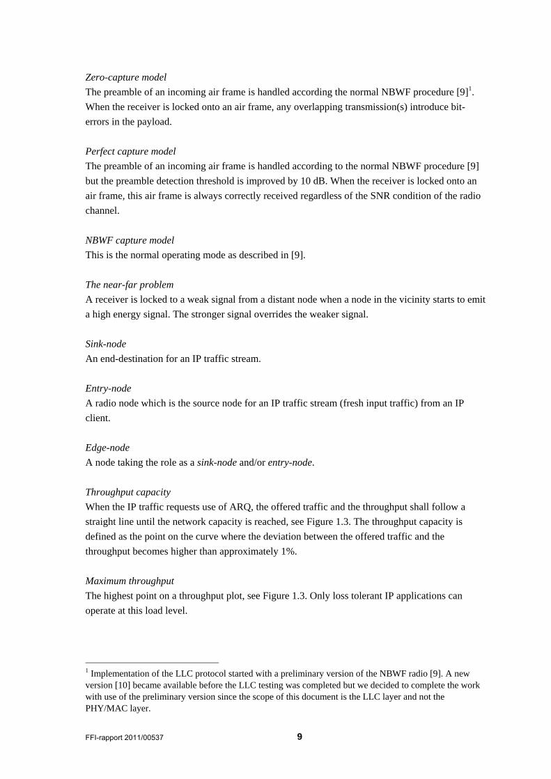
Throughput capacity
When the IP traffic requests use of ARQ, the offered traffic and the throughput shall follow a
straight line until the network capacity is reached, see Figure 1.3. The throughput capacity is
defined as the point on the curve where the deviation between the offered traffic and the
throughput becomes higher than approximately 1%.
Maximum throughput
The highest point on a throughput plot, see Figure 1.3. Only loss tolerant IP applications can
operate at this load level.
1 Implementation of the LLC protocol started with a preliminary version of the NBWF radio [9]. A new version [10] became available before the LLC testing was completed but we decided to complete the work with use of the preliminary version since the scope of this document is the LLC layer and not the PHY/MAC layer.
10 FFI-rapport 2011/00537
Throughputcapacity
Throughput
Offered traffic G Offered traffic G
G = g1 G = g1
End‐to‐enddelay
Maximumthroughput
operating area for loss sensitive IP applications
Figure 1.3 Throughput and delay plot examples.
2 Overview of the Protocol
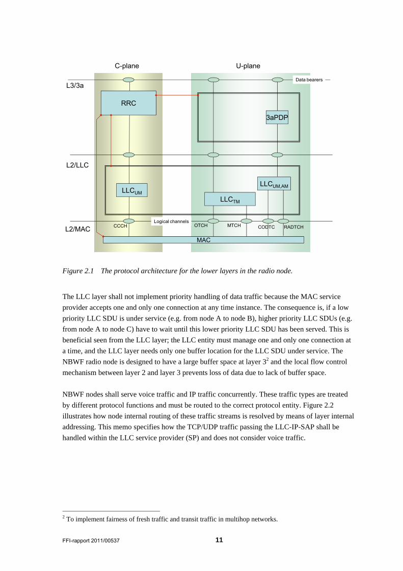
The protocol architecture for the NBWF radio node is described in [7]. Figure 2.1 illustrates the
location of the LLC layer within this hierarchy. The LLC layer provides a connectionless (CL)
mode service towards the upper layer based on the MAC connection (CO) mode service and the
MAC CL-mode service, see section 2.2. The difference between a CO-mode service and a CL-
mode service is that a CO-mode service transfers data over logical connections and hence, the
service must include service primitives to establish connections and release connections. The
terms CO-mode and CL-mode do not express anything about reliability; a CL-mode service may
have a lower error rate than a CO-mode service.
The LLC protocol includes the following elements of procedure described in detail later in this
memo:
- Implements a selective repeat protocol for retransmission of lost data (DT) protocol
data units (PDUs)
- Segmentation of LLC service data units (SDUs) into a number of DT PDUs when the
size exceeds the maximum size of the MAC SDU
- Executes segmentation on a per DT PDU basis to cope with reduction of maximum
MAC SDU size when retransmitting DT PDUs
- Lifetime control of LLC SDUs
FFI-rapport 2011/00537 11
MAC
L2/MAC
L2/LLC
L3/3a
CCCH
RRC
OTCH
C-plane U-plane
LLCUM
MTCH RADTCH
LLCUM,AM
3aPDP
Logical channels
LLCTM
Data bearers
CODTC
Figure 2.1 The protocol architecture for the lower layers in the radio node.
The LLC layer shall not implement priority handling of data traffic because the MAC service
provider accepts one and only one connection at any time instance. The consequence is, if a low
priority LLC SDU is under service (e.g. from node A to node B), higher priority LLC SDUs (e.g.
from node A to node C) have to wait until this lower priority LLC SDU has been served. This is
beneficial seen from the LLC layer; the LLC entity must manage one and only one connection at
a time, and the LLC layer needs only one buffer location for the LLC SDU under service. The
NBWF radio node is designed to have a large buffer space at layer 32 and the local flow control
mechanism between layer 2 and layer 3 prevents loss of data due to lack of buffer space.
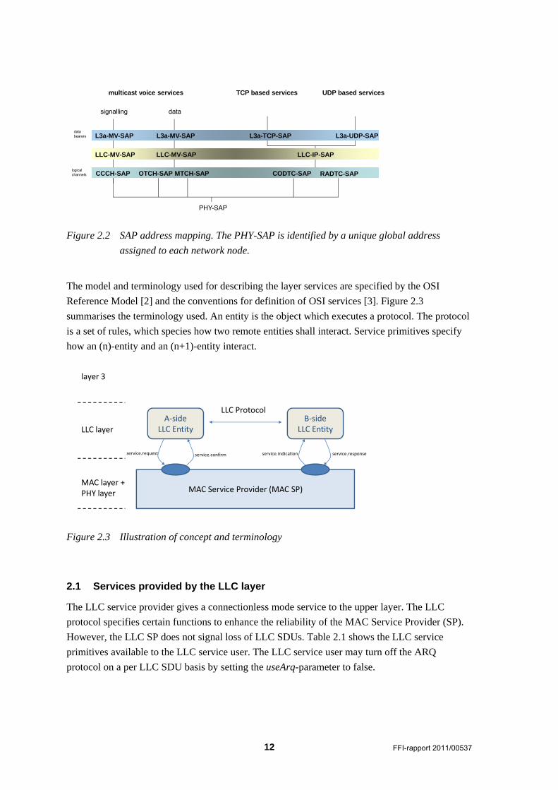
NBWF nodes shall serve voice traffic and IP traffic concurrently. These traffic types are treated
by different protocol functions and must be routed to the correct protocol entity. Figure 2.2
illustrates how node internal routing of these traffic streams is resolved by means of layer internal
addressing. This memo specifies how the TCP/UDP traffic passing the LLC-IP-SAP shall be
handled within the LLC service provider (SP) and does not consider voice traffic.
2 To implement fairness of fresh traffic and transit traffic in multihop networks.
12 FFI-rapport 2011/00537
multicast voice services
L3a-MV-SAP
LLC-MV-SAP
CCCH-SAP
L3a-MV-SAP
LLC-MV-SAP
OTCH-SAP MTCH-SAP
TCP based services
L3a-TCP-SAP
LLC-IP-SAP
CODTC-SAP
UDP based services
L3a-UDP-SAP
PHY-SAP
logicalchannels
data bearers
signalling data
RADTC-SAP
Figure 2.2 SAP address mapping. The PHY-SAP is identified by a unique global address
assigned to each network node.
The model and terminology used for describing the layer services are specified by the OSI
Reference Model [2] and the conventions for definition of OSI services [3]. Figure 2.3
summarises the terminology used. An entity is the object which executes a protocol. The protocol
is a set of rules, which species how two remote entities shall interact. Service primitives specify
how an (n)-entity and an (n+1)-entity interact.
MAC Service Provider (MAC SP)
A‐sideLLC Entity
B‐sideLLC Entity
LLC Protocol
service.request service.indication service.responseservice.confirm
MAC layer +PHY layer
LLC layer
layer 3
Figure 2.3 Illustration of concept and terminology
2.1 Services provided by the LLC layer
The LLC service provider gives a connectionless mode service to the upper layer. The LLC
protocol specifies certain functions to enhance the reliability of the MAC Service Provider (SP).
However, the LLC SP does not signal loss of LLC SDUs. Table 2.1 shows the LLC service
primitives available to the LLC service user. The LLC service user may turn off the ARQ
protocol on a per LLC SDU basis by setting the useArq-parameter to false.
FFI-rapport 2011/00537 13
Parameter request indication
Destination Address M M(=)
Source Address M M(=)
QoS:Priority (integer range 0…3) M M(=)
QoS:useArq (bool) M
Payload O O(=)
Interface Control Information (ICI)
remainingLifetime (double > 0) [sec] M M
Table 2.1 LLC Data service primitives
2.2 Services assumed from the MAC layer
This section includes an overview on how the LLC layer entity uses the MAC service to make it
easier to understand chapter 3.
The MAC service provider supports a CO-mode service on the CODTC SAP and a CL-mode
service on the RADTC SAP (random access data channel). The MAC service user determines
which of these SAPs to use but this memo does not consider the use of the CL-mode MAC
service.
The LLC entity must set up and disconnect connections when using the MAC CO-mode service.
For each SDU received from the upper layer, the LLCE establishes a MAC connection, transfers
the LLC SDU and then releases the connection. A frequent event is to receive a MAC-
Disconnect.indication as the response to a MAC-Connect.request. This is the result of losing the
competition for channel access and the LLC entity will not delete the outgoing LLC SDU but
serve it at a later time. The LLC protocol has no error recovery functions to handle lost MAC
connections during the data transfer phase, since this should be an infrequent event and the
outgoing LLC SDU is deleted silently.
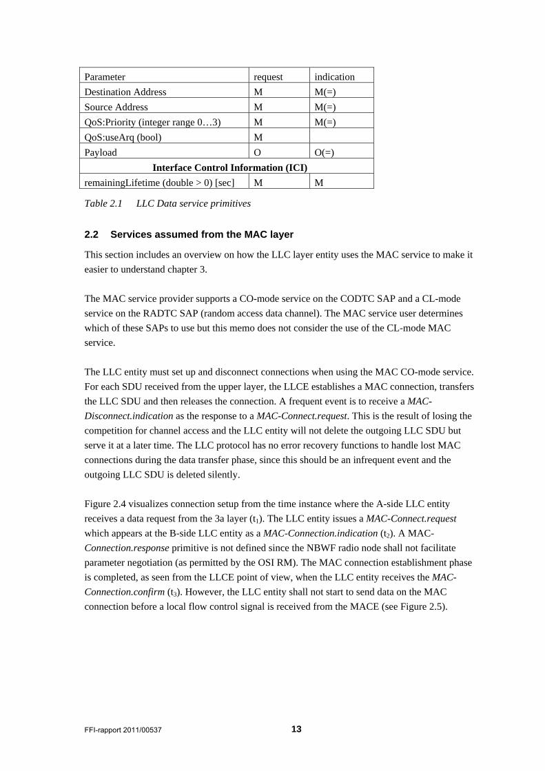
Figure 2.4 visualizes connection setup from the time instance where the A-side LLC entity
receives a data request from the 3a layer (t1). The LLC entity issues a MAC-Connect.request
which appears at the B-side LLC entity as a MAC-Connection.indication (t2). A MAC-
Connection.response primitive is not defined since the NBWF radio node shall not facilitate
parameter negotiation (as permitted by the OSI RM). The MAC connection establishment phase
is completed, as seen from the LLCE point of view, when the LLC entity receives the MAC-
Connection.confirm (t3). However, the LLC entity shall not start to send data on the MAC
connection before a local flow control signal is received from the MACE (see Figure 2.5).
14 FFI-rapport 2011/00537
A-MACA-LLC B-MAC B-LLC
MAC-Connect.request MAC-Connect.indication
MAC-Connect.confirm
t1 t2
LLCE connected
∆t=0
t3
LLC-Data.request
Figure 2.4 LLC connection establishment. These MAC service primitives are passed over port
d83 in the simulator.
Table 2.2 specifies the parameters included in the MAC connect service primitives. The A-side
LLC entity assigns the connection identifier3 to be used in the data transfer phase and passes this
information as an ICI parameter.
Parameter request indication response confirm
Destination Address M M(=) not available -
Source Address M M(=) -
QoS:Priority M M(=)
Interface Control Information (ICI)
Connection Endpoint Identifier (CEID) M M(=)4 M(=)
Table 2.2 MAC Connect service primitives. These primitives go via port d83 in the simulator.
When the MAC connection has been established, the LLC entity shall issue a MAC-Data.request
(on port d83) without any delay each time the MAC entity sends the local control signal
sduRequest (on port c83), see Figure 2.5.
3 Not actually needed since the MAC SAP can have only one connection at time. An argument for including this parameter follows later in this memo. 4 They are semantically identical but may have different numerical values
FFI-rapport 2011/00537 15
A-MACA-LLC B-MAC B-LLC
MAC-Data.request
MAC-Data.indication
t1
t3
LLCE connected
∆t=0
port: c83
t2
sduRequest
port: d83
MAC-Data.request
MAC-Data.indication
tn
tn+2
∆t=0
port: c83
tn+1
sduRequest
port: d83
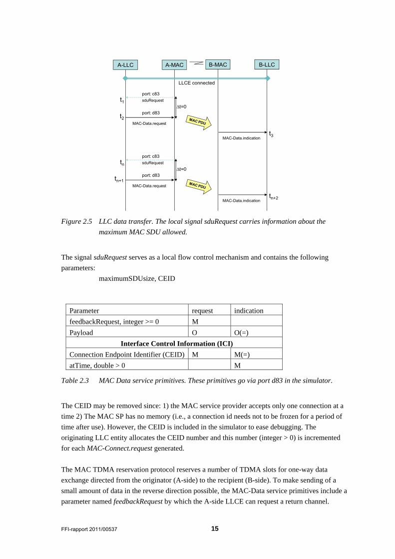
Figure 2.5 LLC data transfer. The local signal sduRequest carries information about the
maximum MAC SDU allowed.
The signal sduRequest serves as a local flow control mechanism and contains the following
parameters:
maximumSDUsize, CEID
Parameter request indication
feedbackRequest, integer >= 0 M
Payload O O(=)
Interface Control Information (ICI)
Connection Endpoint Identifier (CEID) M M(=)
atTime, double > 0 M
Table 2.3 MAC Data service primitives. These primitives go via port d83 in the simulator.
The CEID may be removed since: 1) the MAC service provider accepts only one connection at a
time 2) The MAC SP has no memory (i.e., a connection id needs not to be frozen for a period of
time after use). However, the CEID is included in the simulator to ease debugging. The
originating LLC entity allocates the CEID number and this number (integer > 0) is incremented
for each MAC-Connect.request generated.
The MAC TDMA reservation protocol reserves a number of TDMA slots for one-way data
exchange directed from the originator (A-side) to the recipient (B-side). To make sending of a
small amount of data in the reverse direction possible, the MAC-Data service primitives include a
parameter named feedbackRequest by which the A-side LLCE can request a return channel.
16 FFI-rapport 2011/00537
The A-side LLC entity must know the size of the reverse data (LLC ACK PDU) and subtract this
value from the maximum MAC SDU size signalled by the MAC service provider when it sends a
DT PDU to be followed by an ACK PDU (since the A->B data and the B->A data must share the
TDMA resource reserved).
Note: LLC PDUs are sent over MAC connections using the MAC-Data service primitives. A
fundamental characteristic of the OSI reference model is that a layer entity shall not know the
type of the PDU sent by the entity above. The intention of the OSI RM is to use service primitives
and parameters to develop special features. The part of the TDMA frame allocated to LLC level
acknowledgement is therefore named feedback channel and not LLC ACK PDU slot.
The B-side LLC entity becomes aware of the feedback request when receiving the indication
primitive, t3 in Figure 2.6. This primitive also depicts the time instance at which the feedback
channel is ready for use. The B-side LLC entity implements one timer to manage the feedback
channel and this timer is restarted using the time value signalled, each time a MAC-
Data.indication is received. When the timer expires, the B-side LLC entity issues a MAC-
Data.request without any delay.
The feedbackRequest parameter is used by the sending LLCE to inform the receiving LLCE that
it needs an acknowledgement. The parameter is an integer type with the following semantics;
send an acknowledgement after the n’th MAC SDUs received counted from this one. The sending
LLC entity sets the feedbackRequest parameter to point to the last segment of the LLC SDU to be
followed by an LLC ACK PDU, which means that the parameter is decremented for each MAC
SDU sent. However, if a MAC SDU contains a segment transmitted earlier (retransmitted LLC
DT PDU) and the segment size has changed (e.g., the original LLC DT PDU must be segmented
into two shorter DT PDUs), the sending LLC must adjust the feedbackRequest parameter
accordingly.
Whenever the sending LLC entity sends the last LLC DT PDU after which an acknowledgement
is expected, the LLC must subtract the LLC ACK PDU size from the maximumMacSduSize
signalled by the MAC SP signal sduRequest.
The maximum MAC SDU size allowed is a time variant parameter which depends on TDMA slot
reservation status. Therefore the LLC entity must get this information before the segmentation
procedure is applied. This information is determined by the local MAC entity, and the interface
control information (ICI) signal named sduRequest in Figure 2.6 is the bearer of this information.
The mission of this signal is to tell the local LLC entity that:
a) the LLCE shall immediately send a MAC SDU (by issuing a MAC-Data.request)
b) the MAC SDU size shall be less or equal to the maximum MAC SDU size
FFI-rapport 2011/00537 17
A-MACA-LLC B-MAC B-LLC
MAC-Data.requestfeedbackRequest=1
MAC-Data.indicationatTime=a
t1
t3
LLCE connected
∆t=0
t2
sduRequest
MAC-Data.indicationatTime=now
tn
tn+3
∆t=0
tn+1
sduRequest
LLC DT PDU
LLC DT PDU
LLC ACK PDU
∆t>0
MAC-Data.request
MAC-Data.indication
LLC ACK PDU
MAC-Data.requestfeedbackRequest=0
t4=at5
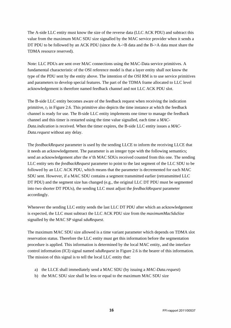
Figure 2.6 Time-sequence diagram when the originating LLC entity requests an
acknowledgement from its peer entity. The LLC PDUs are internal data units used
by the LLC level peer-entities.
The MAC-Disconnect service primitive is used by the A-side LLC entity to release a MAC
connection after use, see Table 2.4. The MAC service provider may issue a MAC-
Disconnect.indication at any point in time determined by internal matters. The MAC-
Disconnect.confirm is a response to the request and is generated at the A-side when the local
MAC entity receives a MAC disconnect confirm PDU, or it’s disconnect timer expires. The
MAC-Disconnect.confirm primitive was introduced to facilitate MAC connection setup delay
measurements that exclude the disconnect delay of the previous connection.
Parameter request indication confirm
Has no parameters
Interface Control Information (ICI)
Connection Endpoint Identifier (CEID) M M M
Table 2.4 MAC Disconnect service primitives. These primitives go via port d83 in the
simulator.
18 FFI-rapport 2011/00537
The LLC/MAC interface service primitives are implemented by the following data structure:
3 Elements of Procedure
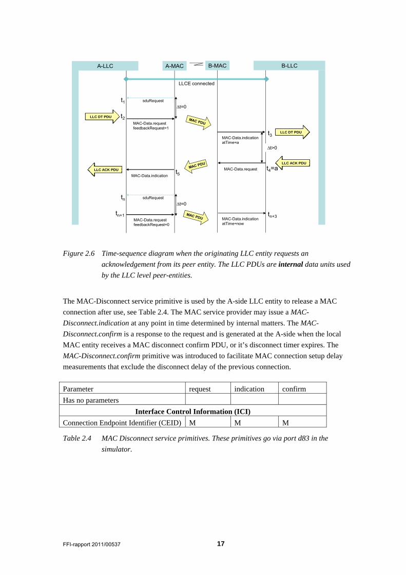
The LLC protocol is specified and implemented as a Finite State Machine (FSM) where a set of
protocol functions are executed as the machine switches from one state to another, see Figure 3.1.
The purpose of this chapter is to specify these protocol functions.
Figure 3.1 Simplified FSM diagram for the A-side LLCE (left) and the B-side LLCE
3.1 Connection Establishment
The purpose of the connection establishment procedure (class ConnectionCache) is to establish a
MAC connection to serve a single LLC SDU. When the LLC SDU has been served, a connection
release procedure is invoked.
message LlcMacInterface
{
int servicePrimitiveType; // port d83 {connect,data,disconnect}={0,1,2}
int sap; //
int ceid;
int priority;
int destinationAddress;
int sourceAddress;
int feedbackRequest;
double atTime;
}
FFI-rapport 2011/00537 19
3.2 LLC SDU Transfer
The LLC SDU transfer procedure is used to convey an LLC SDU in the payload field of the
MAC-Data.request service primitive. This would have been an easy task if the LLC SDUs are
smaller than the maximum MAC SDU size and if the LLCE could accept the MAC SDU loss
probability. However, the LLCE must implement a segmentation function to transfer one LLC
SDU as multiple MAC SDUs and handle unsignalled loss of MAC SDUs. The LLC SDU transfer
procedure will therefore invoke a number of other procedures.
3.3 Normal Release
The release procedure is used by the LLCE to terminate incoming and outgoing connections.
The release procedure for an outgoing connection is either initiated as a result of an internal
protocol event, or by a MAC-SP initiated disconnect (MAC-Disconnect.indication). In the former
case, the outgoing connection is cleared by deleting all internal data belonging to the connection
and then issuing a MAC-Disconnect.request. No confirmation of receipt is expected from the peer
entity but the local MAC entity (A-side) shall issue a MAC-Disconnect.confirm.
The release procedure for an incoming connection (B-side) is initiated upon receiving a MAC-
Disconnect.indication. Internal data structures are cleared immediately together with any partially
received LLC SDU.
3.4 LLC SDU Lifetime Control
Many upper layer protocols demand a guaranteed maximum lifetime of packets within a network
to facilitate reuse of unique identifiers. This fact also applies to the NBWF intra network layer
protocols. A lifetime control function can be based on a hop counter and a delay measurement
function within each radio node. Another approach is to let the application signal a maximum
lifetime and decrement this value as time passes. We propose the latter approach for NBWF.
The purpose of lifetime control is to guarantee a maximum lifetime of LLC SDUs within the LLC
service provider. The LLC service user signals a maximum lifetime. When this time limit is
reached, the discard LLC SDU procedure is applied.
The lifetime must be carried to the remote node and could be done at any layer. Only the LLC
layer or the MAC layer can measure the internal node delay accurately5. The remaining lifetime is
carried as LLC PCI.
3.5 Duplicate Filtering
Loss of acknowledgements and retransmission of DT PDUs may lead to duplicated DT PDUs.
The purpose of duplicate filtering is to discard DT PDUs that are copy of older ones. This
function uses the First Byte Number (FBN) and the MAC SDU size information to detect
duplicates, see section 3.8. 5 The 3a layer protocol entities have none internal functions to measure service time.
20 FFI-rapport 2011/00537
3.6 Discard LLC SDU
The purpose of the discard LLC SDU procedure is to abort the LLC SDU under service. At the A-
side this happens when the maximum lifetime of the SDU is reached, or the maximum number of
retransmissions of a DT PDU is exceeded. In those cases, the LLCE applies the normal release
procedure (a special error release procedure is not needed). Both the A-side and the B-side
invokes the discard LLC SDU function upon receiving a MAC-Disconnect.indication. The LLC
service user is never informed about the discard event.
3.7 Segmentation and Reassembly of LLC SDUs
The purpose of segmentation (A-side only) and reassembly (B-side only) is to facilitate transfer
of LLC SDUs that are too large to be carried by a single MAC SDU. Segmentation (class
SegmentationLlcSdu) is used to map one LLC SDU into a number of LLC Data PDUs.
Reassembly (class ReassemblyLlcSdu) is the complementary process where a number of LLC DT
PDUs is assembled by the receiving peer-entity to maintain the original byte pattern of the LLC
SDU.
In ordinary communication systems, the LLC entity knows the maximum MAC SDU size
allowed when the segmentation function starts. However, this is not the case for NBWF. Here the
maximum MAC SDU size might change during the transfer of the LLC SDU according to the
traffic load on the TDMA slots. The maximum MAC SDU size becomes a function of the
network load level and may either increase or decrease within the transfer time of an LLC SDU.
The maximum LLC SDU sizes allowed is in order of 1580 bytes (preliminary size), and the
segmentation protocol splits the LLC SDU into a number of DT PDUs to fulfil the maximum
MAC SDU size. The maximum MAC SDU size is a time variant parameter. Without ongoing
multicast voice, 4 TDMA slots are available for data traffic in a network with two voice relays.
With merged TDMA slots, a single radio burst encompasses more than one slot; the first slot can
carry 8 bytes payload [(22.5-9)msec*16kbps – 150bits] while subsequent slots can carry 45 bytes
[22.5msec*16kbps]. The maximum MAC SDU size is then 143 bytes when 4 slots are available,
and an LLC SDU containing 1580 bytes must be sent as 11 segments. When only one slot is
available, 198 segments must be used! Long IP packets should therefore be denied service during
the time periods where only one slot is available.
FFI-rapport 2011/00537 21
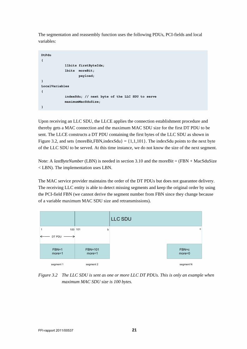
The segmentation and reassembly function uses the following PDUs, PCI-fields and local
variables:
Upon receiving an LLC SDU, the LLCE applies the connection establishment procedure and
thereby gets a MAC connection and the maximum MAC SDU size for the first DT PDU to be
sent. The LLCE constructs a DT PDU containing the first bytes of the LLC SDU as shown in
Figure 3.2, and sets {moreBit,FBN,indexSdu} = {1,1,101}. The indexSdu points to the next byte
of the LLC SDU to be served. At this time instance, we do not know the size of the next segment.
Note: A lastByteNumber (LBN) is needed in section 3.10 and the moreBit = (FBN + MacSduSize
< LBN). The implementation uses LBN.
The MAC service provider maintains the order of the DT PDUs but does not guarantee delivery.
The receiving LLC entity is able to detect missing segments and keep the original order by using
the PCI-field FBN (we cannot derive the segment number from FBN since they change because
of a variable maximum MAC SDU size and retransmissions).
LLC SDU
1 c
FBN=1more=1
100
FBN=101more=1
101 b
segment 1 segment 2
FBN=cmore=0
segment N
DT PDU
Figure 3.2 The LLC SDU is sent as one or more LLC DT PDUs. This is only an example when
maximum MAC SDU size is 100 bytes.
DtPdu
{
11bits firstByteIdx;
1bits moreBit;
payload;
}
LocalVariables
{
indexSdu; // next byte of the LLC SDU to serve
maximumMacSduSize;
}
22 FFI-rapport 2011/00537
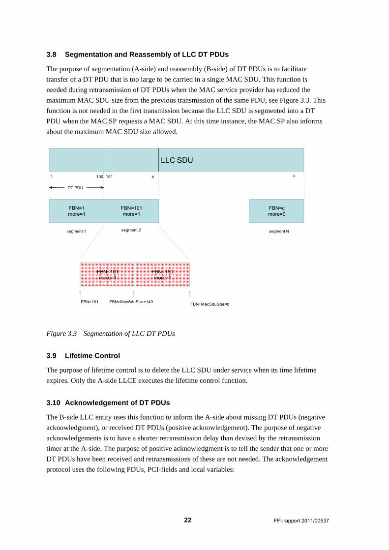
3.8 Segmentation and Reassembly of LLC DT PDUs
The purpose of segmentation (A-side) and reassembly (B-side) of DT PDUs is to facilitate
transfer of a DT PDU that is too large to be carried in a single MAC SDU. This function is
needed during retransmission of DT PDUs when the MAC service provider has reduced the
maximum MAC SDU size from the previous transmission of the same PDU, see Figure 3.3. This
function is not needed in the first transmission because the LLC SDU is segmented into a DT
PDU when the MAC SP requests a MAC SDU. At this time instance, the MAC SP also informs
about the maximum MAC SDU size allowed.
LLC SDU
1 c
FBN=1more=1
100
FBN=101more=1
101 b
segment 1 segment 2
FBN=cmore=0
segment N
DT PDU
FBN=101more=1
FBN=150more=1
FBN+MacSduSize=bFBN+MacSduSize=149FBN=101
Figure 3.3 Segmentation of LLC DT PDUs
3.9 Lifetime Control
The purpose of lifetime control is to delete the LLC SDU under service when its time lifetime
expires. Only the A-side LLCE executes the lifetime control function.
3.10 Acknowledgement of DT PDUs
The B-side LLC entity uses this function to inform the A-side about missing DT PDUs (negative
acknowledgment), or received DT PDUs (positive acknowledgement). The purpose of negative
acknowledgements is to have a shorter retransmission delay than devised by the retransmission
timer at the A-side. The purpose of positive acknowledgment is to tell the sender that one or more
DT PDUs have been received and retransmissions of these are not needed. The acknowledgement
protocol uses the following PDUs, PCI-fields and local variables:
FFI-rapport 2011/00537 23
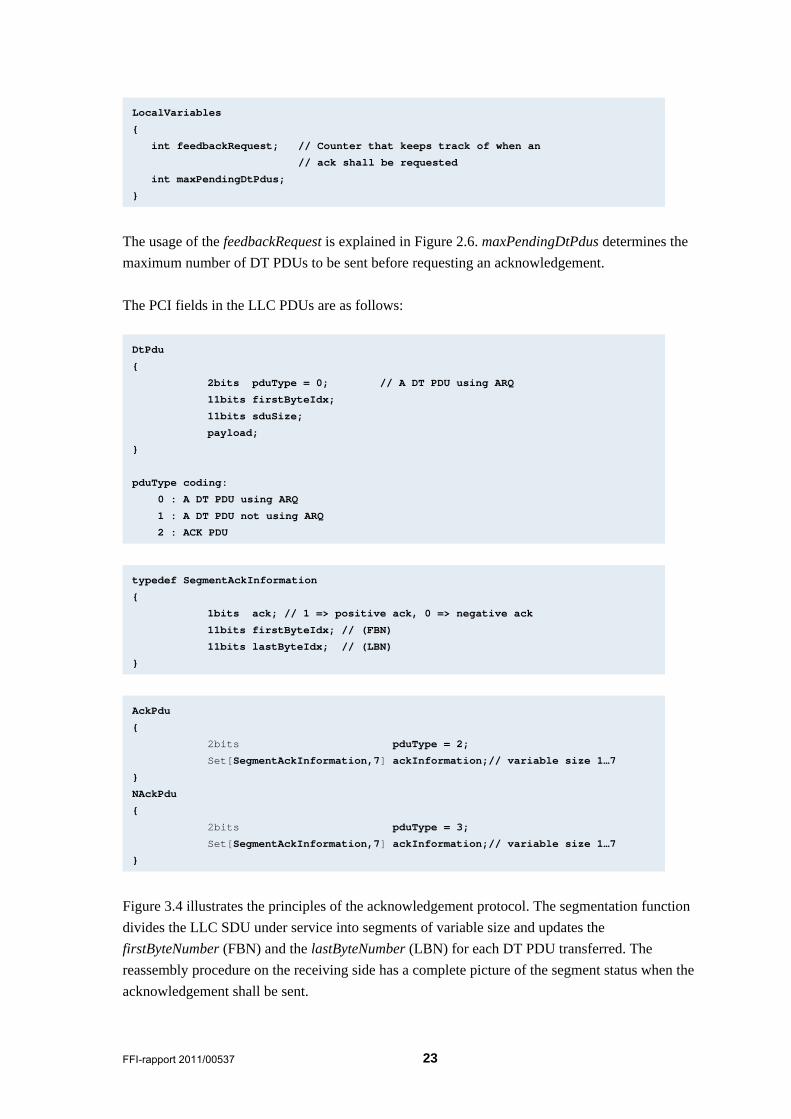
The usage of the feedbackRequest is explained in Figure 2.6. maxPendingDtPdus determines the
maximum number of DT PDUs to be sent before requesting an acknowledgement.
The PCI fields in the LLC PDUs are as follows:
Figure 3.4 illustrates the principles of the acknowledgement protocol. The segmentation function
divides the LLC SDU under service into segments of variable size and updates the
firstByteNumber (FBN) and the lastByteNumber (LBN) for each DT PDU transferred. The
reassembly procedure on the receiving side has a complete picture of the segment status when the
acknowledgement shall be sent.
AckPdu
{
2bits pduType = 2;
Set[SegmentAckInformation,7] ackInformation;// variable size 1…7
}
NAckPdu
{
2bits pduType = 3;
Set[SegmentAckInformation,7] ackInformation;// variable size 1…7
}
typedef SegmentAckInformation
{
1bits ack; // 1 => positive ack, 0 => negative ack
11bits firstByteIdx; // (FBN)
11bits lastByteIdx; // (LBN)
}
DtPdu
{
2bits pduType = 0; // A DT PDU using ARQ
11bits firstByteIdx;
11bits sduSize;
payload;
}
pduType coding:
0 : A DT PDU using ARQ
1 : A DT PDU not using ARQ
2 : ACK PDU
LocalVariables
{
int feedbackRequest; // Counter that keeps track of when an
// ack shall be requested
int maxPendingDtPdus;
}
24 FFI-rapport 2011/00537
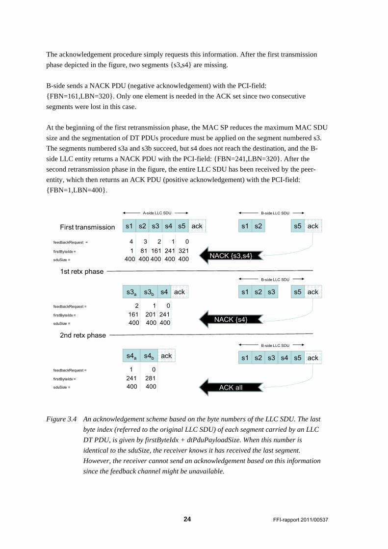
The acknowledgement procedure simply requests this information. After the first transmission
phase depicted in the figure, two segments {s3,s4} are missing.
B-side sends a NACK PDU (negative acknowledgement) with the PCI-field:
{FBN=161,LBN=320}. Only one element is needed in the ACK set since two consecutive
segments were lost in this case.
At the beginning of the first retransmission phase, the MAC SP reduces the maximum MAC SDU
size and the segmentation of DT PDUs procedure must be applied on the segment numbered s3.
The segments numbered s3a and s3b succeed, but s4 does not reach the destination, and the B-
side LLC entity returns a NACK PDU with the PCI-field: {FBN=241,LBN=320}. After the
second retransmission phase in the figure, the entire LLC SDU has been received by the peer-
entity, which then returns an ACK PDU (positive acknowledgement) with the PCI-field:
{FBN=1,LBN=400}.
s1 s2
s3a s4
s5
ack
A-side LLC SDU
s1 s2 s5 ack
B-side LLC SDU
feedbackRequest = 4 3 2 1 0
First transmission
1st retx phase
NACK {s3,s4}
s3 s4 ack
feedbackRequest = 2 1 0
2nd retx phase
s1 s2 s5 ack
NACK {s4}
s3
B-side LLC SDU
s1 s2 s5 ack
ACK all
s3
B-side LLC SDU
s4
firstByteIdx = 1 81 161 241 321sduSize = 400 400 400 400 400
s3b
s4a ack
feedbackRequest = 1 0
s4b
firstByteIdx = 161 201 241 sduSize = 400 400 400
firstByteIdx = 241 281sduSize = 400 400
Figure 3.4 An acknowledgement scheme based on the byte numbers of the LLC SDU. The last
byte index (referred to the original LLC SDU) of each segment carried by an LLC
DT PDU, is given by firstByteIdx + dtPduPayloadSize. When this number is
identical to the sduSize, the receiver knows it has received the last segment.
However, the receiver cannot send an acknowledgement based on this information
since the feedback channel might be unavailable.
FFI-rapport 2011/00537 25
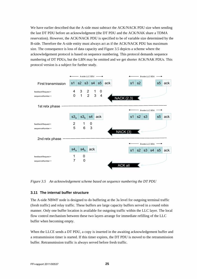
We have earlier described that the A-side must subtract the ACK/NACK PDU size when sending
the last DT PDU before an acknowledgment (the DT PDU and the ACK/NAK share a TDMA
reservation). However, the ACK/NACK PDU is specified to be of variable size determined by the
B-side. Therefore the A-side entity must always act as if the ACK/NACK PDU has maximum
size. The consequence is loss of data capacity and Figure 3.5 depicts a scheme where the
acknowledgement protocol is based on sequence numbering. This protocol demands sequence
numbering of DT PDUs, but the LBN may be omitted and we get shorter ACK/NAK PDUs. This
protocol version is a subject for further study.
s1 s2
s3a s4
s5
ack
A-side LLC SDU
s1 s2 s5 ack
B-side LLC SDU
feedbackRequest = 4 3 2 1 0
First transmission
1st retx phase
NACK {2,3}
s3 s4 ack
feedbackRequest = 2 1 0
2nd retx phase
s1 s2 s5 ack
NACK {3}
s3
B-side LLC SDU
s1 s2 s5 ack
ACK all
s3
B-side LLC SDU
s4
sequenceNumber = 0 1 2 3 4
s3b
sequenceNumber = 5 6 3
s4a ack
feedbackRequest = 1 0
s4b
sequenceNumber = 7 0
Figure 3.5 An acknowledgement scheme based on sequence numbering the DT PDU
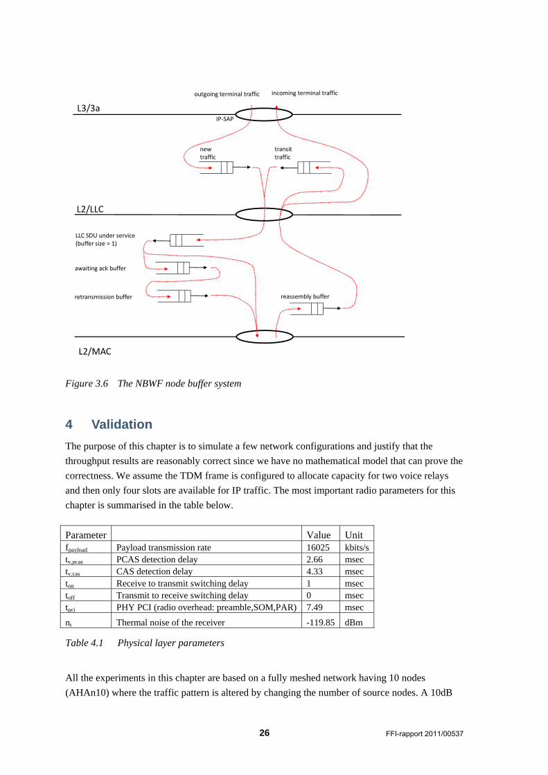
3.11 The internal buffer structure
The A-side NBWF node is designed to do buffering at the 3a level for outgoing terminal traffic
(fresh traffic) and relay traffic. These buffers are large capacity buffers served in a round robin
manner. Only one buffer location is available for outgoing traffic within the LLC layer. The local
flow control mechanism between these two layers arrange for immediate refilling of the LLC
buffer when becoming empty.
When the LLCE sends a DT PDU, a copy is inserted in the awaiting acknowledgement buffer and
a retransmission timer is started. If this timer expires, the DT PDU is moved to the retransmission
buffer. Retransmission traffic is always served before fresh traffic.
26 FFI-rapport 2011/00537
L2/LLC
L2/MAC
L3/3aIP‐SAP
newtraffic
transittraffic
incoming terminal traffic
LLC SDU under service (buffer size = 1)
retransmission buffer
awaiting ack buffer
reassembly buffer
outgoing terminal traffic
Figure 3.6 The NBWF node buffer system
4 Validation
The purpose of this chapter is to simulate a few network configurations and justify that the
throughput results are reasonably correct since we have no mathematical model that can prove the
correctness. We assume the TDM frame is configured to allocate capacity for two voice relays
and then only four slots are available for IP traffic. The most important radio parameters for this
chapter is summarised in the table below.
Parameter Value Unit fpayload Payload transmission rate 16025 kbits/s tv,pcas PCAS detection delay 2.66 msec tv,cas CAS detection delay 4.33 msec ton Receive to transmit switching delay 1 msec toff Transmit to receive switching delay 0 msec tpci PHY PCI (radio overhead: preamble,SOM,PAR) 7.49 msec
nt Thermal noise of the receiver -119.85 dBm
Table 4.1 Physical layer parameters
All the experiments in this chapter are based on a fully meshed network having 10 nodes
(AHAn10) where the traffic pattern is altered by changing the number of source nodes. A 10dB
FFI-rapport 2011/00537 27
link loss provide for high signal levels at the receivers and a data packet sent on an established
MAC connection will always reach the destination.
The current version of the MAC protocol uses a very short scheduling interval [0,3 ]slotrandUni t compared to the vulnerable period, and the current version does not support
larger random delay. It is necessary to increase this scheduling interval since the theoretical MAC
CR PDU collision probability may reach 0.33 for the AHAn10 network. However, this chapter
shall test the LLC layer only and we do not modify the MAC layer. The consequence of operating
with this high collision rate is a high connection establishment failure rate. To compensate for the
high collision rate, all the experiments are setup to use the perfect capture model provided by the
simulator. Moreover, the preamble detection threshold is moved from 0dB to -10dB such that the
preamble can survive a number overlapping transmissions.
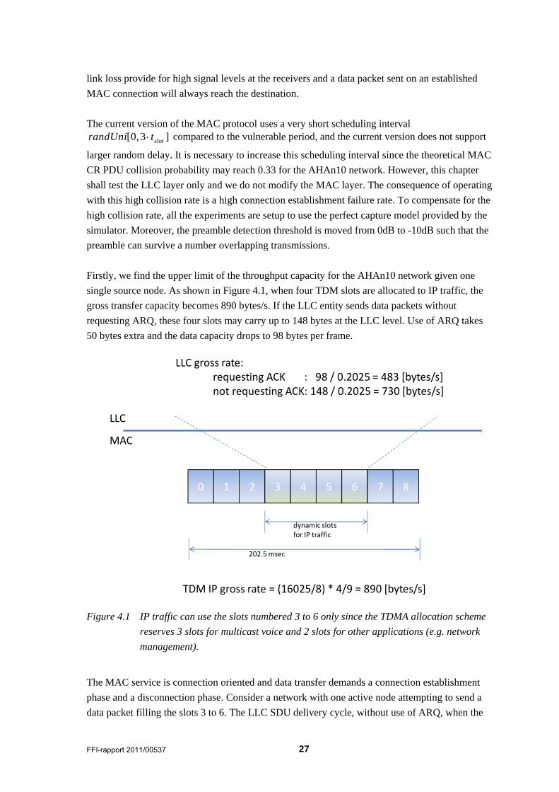
Firstly, we find the upper limit of the throughput capacity for the AHAn10 network given one
single source node. As shown in Figure 4.1, when four TDM slots are allocated to IP traffic, the
gross transfer capacity becomes 890 bytes/s. If the LLC entity sends data packets without
requesting ARQ, these four slots may carry up to 148 bytes at the LLC level. Use of ARQ takes
50 bytes extra and the data capacity drops to 98 bytes per frame.
0 1 2 3 4 5 6 7 8
dynamic slotsfor IP traffic
TDM IP gross rate = (16025/8) * 4/9 = 890 [bytes/s]
LLC
MAC
LLC gross rate:requesting ACK : 98 / 0.2025 = 483 [bytes/s]not requesting ACK: 148 / 0.2025 = 730 [bytes/s]
202.5 msec
Figure 4.1 IP traffic can use the slots numbered 3 to 6 only since the TDMA allocation scheme
reserves 3 slots for multicast voice and 2 slots for other applications (e.g. network
management).
The MAC service is connection oriented and data transfer demands a connection establishment
phase and a disconnection phase. Consider a network with one active node attempting to send a
data packet filling the slots 3 to 6. The LLC SDU delivery cycle, without use of ARQ, when the
28 FFI-rapport 2011/00537
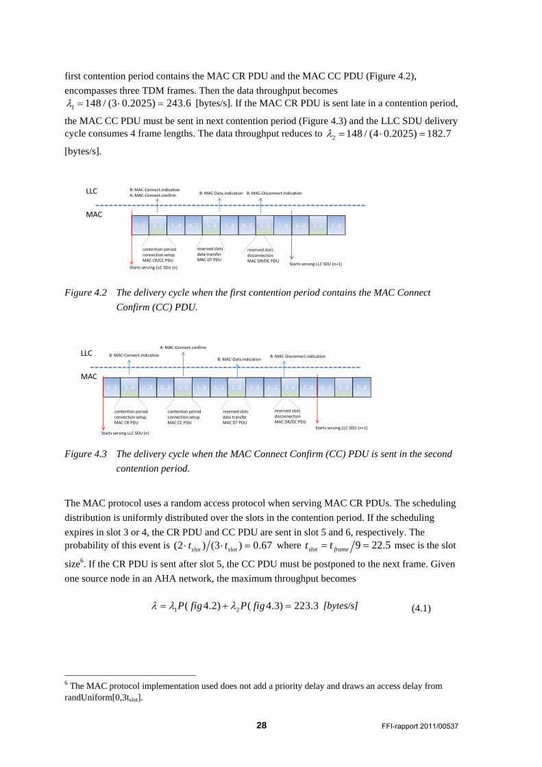
first contention period contains the MAC CR PDU and the MAC CC PDU (Figure 4.2),
encompasses three TDM frames. Then the data throughput becomes
1 148 / (3 0.2025) 243.6 [bytes/s]. If the MAC CR PDU is sent late in a contention period,
the MAC CC PDU must be sent in next contention period (Figure 4.3) and the LLC SDU delivery cycle consumes 4 frame lengths. The data throughput reduces to 2 148 / (4 0.2025) 182.7
[bytes/s].
0...2 3...6 7...8
LLC
MAC0...2 3...6 7...8 0...2 3...6 7...8
contention periodconnection setupMAC CR/CC PDU
reserved slotsdata transferMAC DT PDU
reserved slotsdisconnectionMAC DR/DC PDU
B: MAC‐Data.indication B: MAC‐Disconnect.indicationB: MAC‐Connect.indicationA: MAC‐Connect.confirm
0...2 3...6 7...8
Starts serving LLC SDU (n)Starts serving LLC SDU (n+1)
Figure 4.2 The delivery cycle when the first contention period contains the MAC Connect
Confirm (CC) PDU.
0...2 3...6 7...8
LLC
MAC0...2 3...6 7...8 0...2 3...6 7...8
B: MAC‐Connect.indication
0...2 3...6 7...8
Starts serving LLC SDU (n)
0...2 3...6 7...8
contention periodconnection setupMAC CR PDU
contention periodconnection setupMAC CC PDU
A: MAC‐Connect.confirm
reserved slotsdata transferMAC DT PDU
B: MAC‐Data.indication
reserved slotsdisconnectionMAC DR/DC PDU
B: MAC‐Disconnect.indication
Starts serving LLC SDU (n+1)
Figure 4.3 The delivery cycle when the MAC Connect Confirm (CC) PDU is sent in the second
contention period.
The MAC protocol uses a random access protocol when serving MAC CR PDUs. The scheduling
distribution is uniformly distributed over the slots in the contention period. If the scheduling
expires in slot 3 or 4, the CR PDU and CC PDU are sent in slot 5 and 6, respectively. The probability of this event is (2 ) (3 ) 0.67slot slott t where 9 22.5slot framet t msec is the slot
size6. If the CR PDU is sent after slot 5, the CC PDU must be postponed to the next frame. Given
one source node in an AHA network, the maximum throughput becomes
1 2( 4.2) ( 4.3) 223.3P fig P fig [bytes/s] (4.1)
6 The MAC protocol implementation used does not add a priority delay and draws an access delay from randUniform[0,3tslot].
FFI-rapport 2011/00537 29
If more than one node is busy, two or more MAC CR PDUs may collide and the throughput
expression is no longer valid. The maximum throughput for the ARQ case is 98 / 148 147.9
bytes/s.
This chapter is organised as follows. The next section specifies the estimators used during
experiments while the next three sections present the experiments.
4.1 Estimators
This section explains how measurements are taken in the simulator.
MAC connection holding time
The latency time between the MAC-Connect.confirm and the corresponding MAC-
Disconnect.confirm. Connection release due to error events (e.g., an LLC SDU lifetime expiry) is
not included in the sample set. Note that this definition encompasses the MAC disconnection
delay. The LLC entity issues a MAC-Disconnect.request with zero delay after the last DT PDU
has been sent down to MAC. This disconnect will be delayed by the MAC entity until it has sent
the MAC SDU on the air. An exact holding time estimator must therefore be implemented by the
MAC layer and not the LLC layer.
MAC connection setup delay
The latency time between the first MAC-Connect.request and the corresponding MAC-
Connect.confirm which results in a MAC connection. Generally, the LLC entity must issue a
number of requests before it wins the channel.
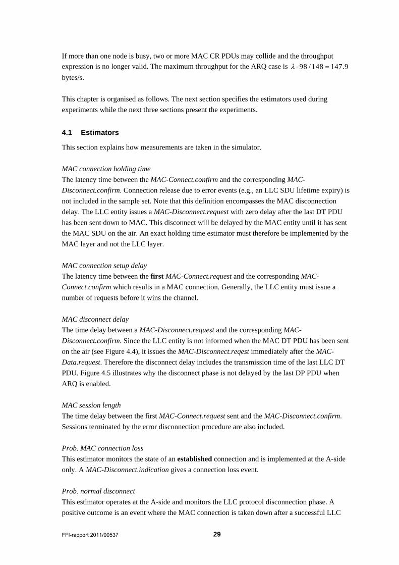
MAC disconnect delay
The time delay between a MAC-Disconnect.request and the corresponding MAC-
Disconnect.confirm. Since the LLC entity is not informed when the MAC DT PDU has been sent
on the air (see Figure 4.4), it issues the MAC-Disconnect.reqest immediately after the MAC-
Data.request. Therefore the disconnect delay includes the transmission time of the last LLC DT
PDU. Figure 4.5 illustrates why the disconnect phase is not delayed by the last DP PDU when
ARQ is enabled.
MAC session length
The time delay between the first MAC-Connect.request sent and the MAC-Disconnect.confirm.
Sessions terminated by the error disconnection procedure are also included.
Prob. MAC connection loss
This estimator monitors the state of an established connection and is implemented at the A-side
only. A MAC-Disconnect.indication gives a connection loss event.
Prob. normal disconnect
This estimator operates at the A-side and monitors the LLC protocol disconnection phase. A
positive outcome is an event where the MAC connection is taken down after a successful LLC
30 FFI-rapport 2011/00537
SDU service phase. A negative outcome is an LLC SDU lifetime expiry event on a half open or
an established MAC connection.
Queue time fresh traffic
This estimator measures the queuing time delay in the fresh traffic input queue. Only packets
which are taken under service by the LLC service provider are included. For example, packets
rejected due to lifetime expiry while residing in the fresh traffic input buffer are not included.
LLC
MACCR CC
MAC‐Connect.req
DT DT DR DC
Connection setup delay(many attempts)
Holding time
Session length
Disconnection delay
Schedulingstarts
CI
Figure 4.4 MAC delivery cycle when ARQ is disabled. Generally a node must compete a
number of times before it wins the channel access.
LLC
MACCR CC
MAC‐Connect.req
DT DT DR DC
Holding time
Session length
Disconnection delay
Schedulingstarts
CIACK
Connection setup delay(many attempts)
Figure 4.5 MAC delivery cycle when ARQ is enabled.
4.2 Experiments with ARQ disabled
The first experiments use a fixed payload size of 148 bytes with the ARQ protocol disabled.
Figure 4.14 explains why the payload is sent as one or two segments. With one single active node
(n=1), the length of the channel idle time is independent of the load level; MAC always starts the
scheduling process at the beginning of slot 3 and the node has none competitors. From Figure
4.14 we conclude that case B in this figure is the most frequent event. This is as expected since the average scheduling delay is 1.5 slott and the CR+CC will occupy the remaining space in the
FFI-rapport 2011/00537 31
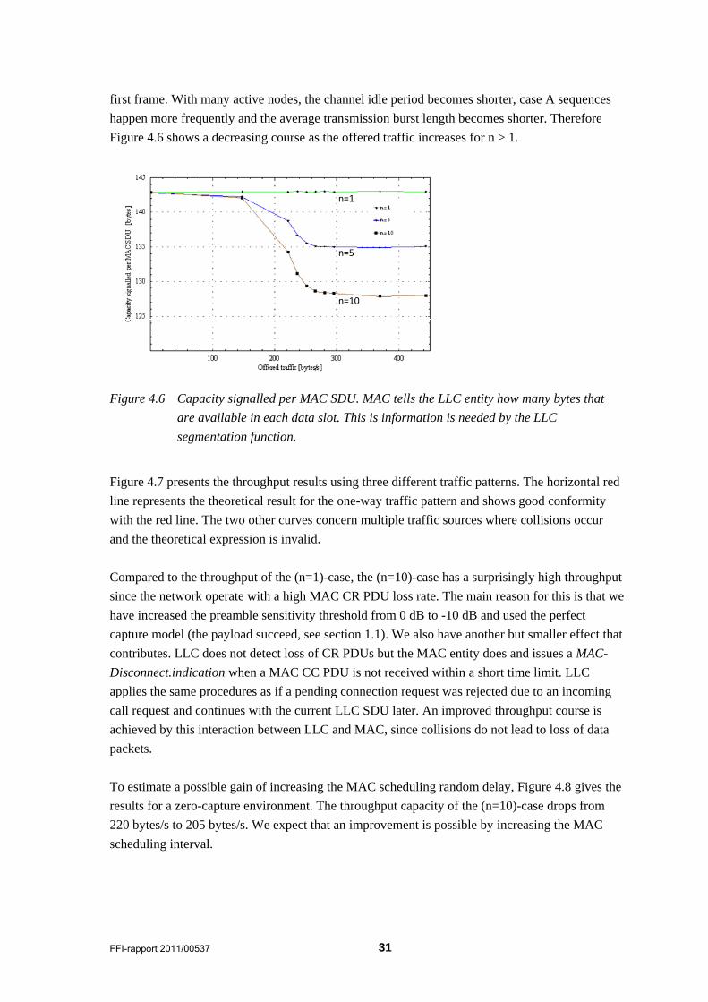
first frame. With many active nodes, the channel idle period becomes shorter, case A sequences
happen more frequently and the average transmission burst length becomes shorter. Therefore
Figure 4.6 shows a decreasing course as the offered traffic increases for n > 1.
n=1
n=5
n=10
Figure 4.6 Capacity signalled per MAC SDU. MAC tells the LLC entity how many bytes that
are available in each data slot. This is information is needed by the LLC
segmentation function.
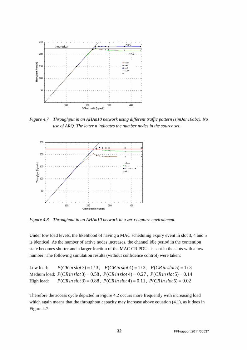
Figure 4.7 presents the throughput results using three different traffic patterns. The horizontal red
line represents the theoretical result for the one-way traffic pattern and shows good conformity
with the red line. The two other curves concern multiple traffic sources where collisions occur
and the theoretical expression is invalid.
Compared to the throughput of the (n=1)-case, the (n=10)-case has a surprisingly high throughput
since the network operate with a high MAC CR PDU loss rate. The main reason for this is that we
have increased the preamble sensitivity threshold from 0 dB to -10 dB and used the perfect
capture model (the payload succeed, see section 1.1). We also have another but smaller effect that
contributes. LLC does not detect loss of CR PDUs but the MAC entity does and issues a MAC-
Disconnect.indication when a MAC CC PDU is not received within a short time limit. LLC
applies the same procedures as if a pending connection request was rejected due to an incoming
call request and continues with the current LLC SDU later. An improved throughput course is
achieved by this interaction between LLC and MAC, since collisions do not lead to loss of data
packets.
To estimate a possible gain of increasing the MAC scheduling random delay, Figure 4.8 gives the
results for a zero-capture environment. The throughput capacity of the (n=10)-case drops from
220 bytes/s to 205 bytes/s. We expect that an improvement is possible by increasing the MAC
scheduling interval.
32 FFI-rapport 2011/00537
theoretical
n=1
n=5
Figure 4.7 Throughput in an AHAn10 network using different traffic pattern (simJan10abc). No
use of ARQ. The letter n indicates the number nodes in the source set.
theoretical
n=1
n=5
Figure 4.8 Throughput in an AHAn10 network in a zero-capture environment.
Under low load levels, the likelihood of having a MAC scheduling expiry event in slot 3, 4 and 5
is identical. As the number of active nodes increases, the channel idle period in the contention
state becomes shorter and a larger fraction of the MAC CR PDUs is sent in the slots with a low
number. The following simulation results (without confidence control) were taken:
Low load: ( 3) 1 / 3P CR in slot , ( 4) 1/ 3P CR in slot , ( 5) 1 / 3P CR in slot
Medium load: ( 3) 0.58P CR in slot , ( 4) 0.27P CR in slot , ( 5) 0.14P CR in slot
High load: ( 3) 0.88P CR in slot , ( 4) 0.11P CR in slot , ( 5) 0.02P CR in slot
Therefore the access cycle depicted in Figure 4.2 occurs more frequently with increasing load
which again means that the throughput capacity may increase above equation (4.1), as it does in
Figure 4.7.
FFI-rapport 2011/00537 33
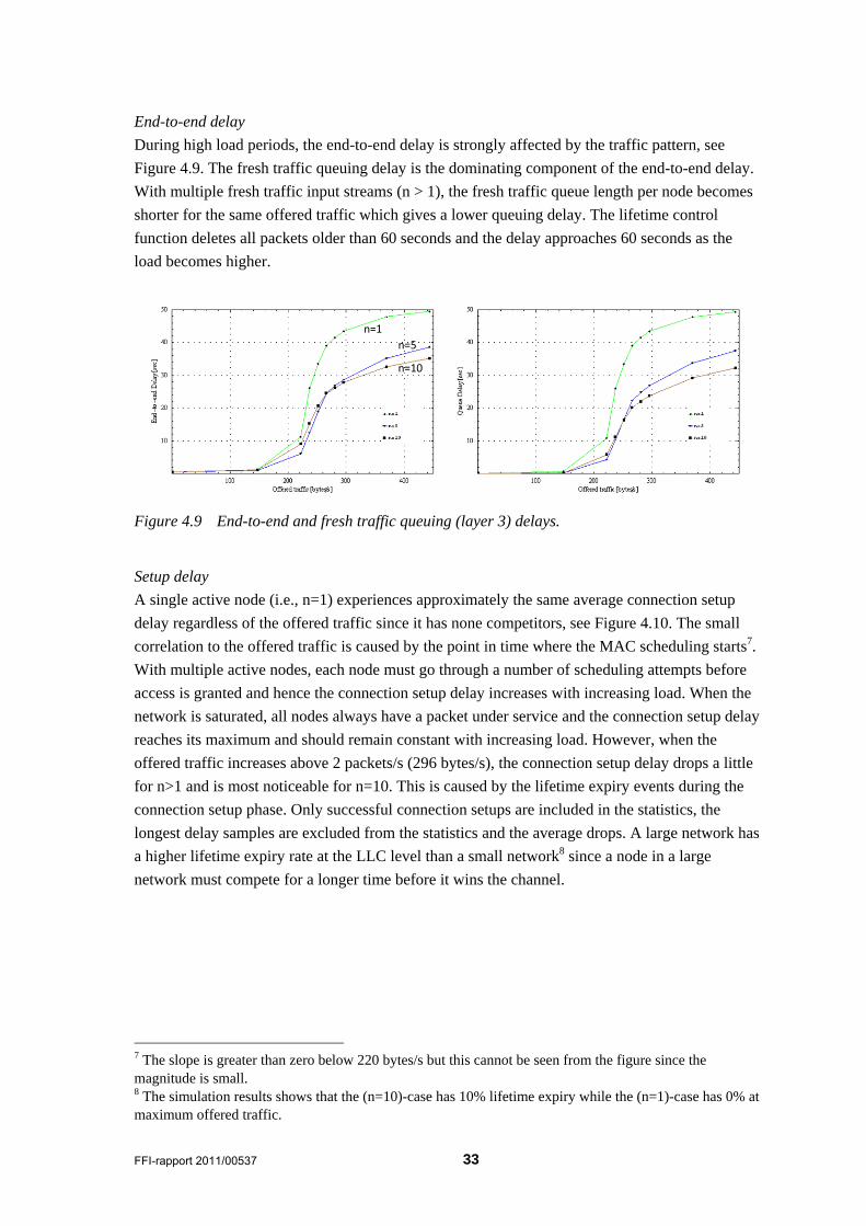
End-to-end delay
During high load periods, the end-to-end delay is strongly affected by the traffic pattern, see
Figure 4.9. The fresh traffic queuing delay is the dominating component of the end-to-end delay.
With multiple fresh traffic input streams (n > 1), the fresh traffic queue length per node becomes
shorter for the same offered traffic which gives a lower queuing delay. The lifetime control
function deletes all packets older than 60 seconds and the delay approaches 60 seconds as the
load becomes higher.
n=1
n=5
n=10
Figure 4.9 End-to-end and fresh traffic queuing (layer 3) delays.
Setup delay
A single active node (i.e., n=1) experiences approximately the same average connection setup
delay regardless of the offered traffic since it has none competitors, see Figure 4.10. The small
correlation to the offered traffic is caused by the point in time where the MAC scheduling starts7.
With multiple active nodes, each node must go through a number of scheduling attempts before
access is granted and hence the connection setup delay increases with increasing load. When the
network is saturated, all nodes always have a packet under service and the connection setup delay
reaches its maximum and should remain constant with increasing load. However, when the
offered traffic increases above 2 packets/s (296 bytes/s), the connection setup delay drops a little
for n>1 and is most noticeable for n=10. This is caused by the lifetime expiry events during the
connection setup phase. Only successful connection setups are included in the statistics, the
longest delay samples are excluded from the statistics and the average drops. A large network has
a higher lifetime expiry rate at the LLC level than a small network8 since a node in a large
network must compete for a longer time before it wins the channel.
7 The slope is greater than zero below 220 bytes/s but this cannot be seen from the figure since the magnitude is small. 8 The simulation results shows that the (n=10)-case has 10% lifetime expiry while the (n=1)-case has 0% at maximum offered traffic.
34 FFI-rapport 2011/00537
n=5
n=10
n=1
Figure 4.10 Connection setup delay (left) and session length vs. offered traffic.
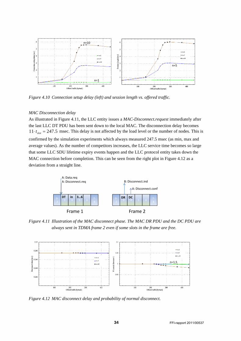
MAC Disconnection delay
As illustrated in Figure 4.11, the LLC entity issues a MAC-Disconnect.request immediately after
the last LLC DT PDU has been sent down to the local MAC. The disconnection delay becomes 11 247.5slott msec. This delay is not affected by the load level or the number of nodes. This is
confirmed by the simulation experiments which always measured 247.5 msec (as min, max and
average values). As the number of competitors increases, the LLC service time becomes so large
that some LLC SDU lifetime expiry events happen and the LLC protocol entity takes down the
MAC connection before completion. This can be seen from the right plot in Figure 4.12 as a
deviation from a straight line.
0‐2
3 4 5 67‐8
0‐2
3 4 5 67‐8
Frame 1 Frame 2
A: Data.reqA: Disconnect.req B: Disconnect.ind
A: Disconnect.conf
DR DCDT in 3…6
Figure 4.11 Illustration of the MAC disconnect phase. The MAC DR PDU and the DC PDU are
always sent in TDMA frame 2 even if some slots in the frame are free.
n=10
n=1,5
Figure 4.12 MAC disconnect delay and probability of normal disconnect.
FFI-rapport 2011/00537 35
4.3 Experiments with ARQ enabled
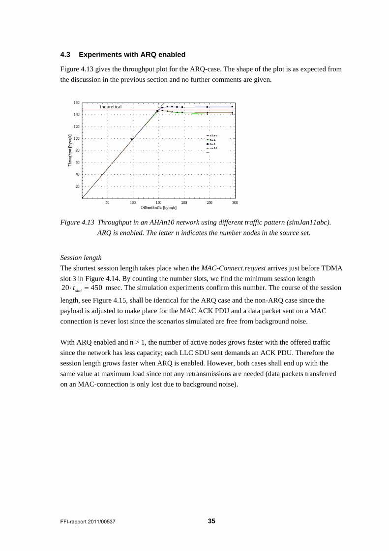
Figure 4.13 gives the throughput plot for the ARQ-case. The shape of the plot is as expected from
the discussion in the previous section and no further comments are given.
theoretical
Figure 4.13 Throughput in an AHAn10 network using different traffic pattern (simJan11abc).
ARQ is enabled. The letter n indicates the number nodes in the source set.
Session length
The shortest session length takes place when the MAC-Connect.request arrives just before TDMA
slot 3 in Figure 4.14. By counting the number slots, we find the minimum session length 20 450slott msec. The simulation experiments confirm this number. The course of the session
length, see Figure 4.15, shall be identical for the ARQ case and the non-ARQ case since the
payload is adjusted to make place for the MAC ACK PDU and a data packet sent on a MAC
connection is never lost since the scenarios simulated are free from background noise.
With ARQ enabled and n > 1, the number of active nodes grows faster with the offered traffic
since the network has less capacity; each LLC SDU sent demands an ACK PDU. Therefore the
session length grows faster when ARQ is enabled. However, both cases shall end up with the
same value at maximum load since not any retransmissions are needed (data packets transferred
on an MAC-connection is only lost due to background noise).
36 FFI-rapport 2011/00537
0‐2
3 4 5 6
7‐8
0‐2
3 4 5 6
7‐8
Frame 1 Frame 2
MAC‐Connect.req
DT/ACKCR CC 0‐2
3 4 5 67‐8
Frame 3
MAC‐Disconnect.conf
DR DC
Session length
0‐2
3 4 5 6
7‐8
0‐2
3 4 5 6
7‐8
Frame 1 Frame 2
MAC‐Connect.req
DT / ACK in 3…6CR CC 0‐2
3 4 5 67‐8
Frame 3
MAC‐Disconnect.conf
DR DC
Session length
DT Case A
Case B
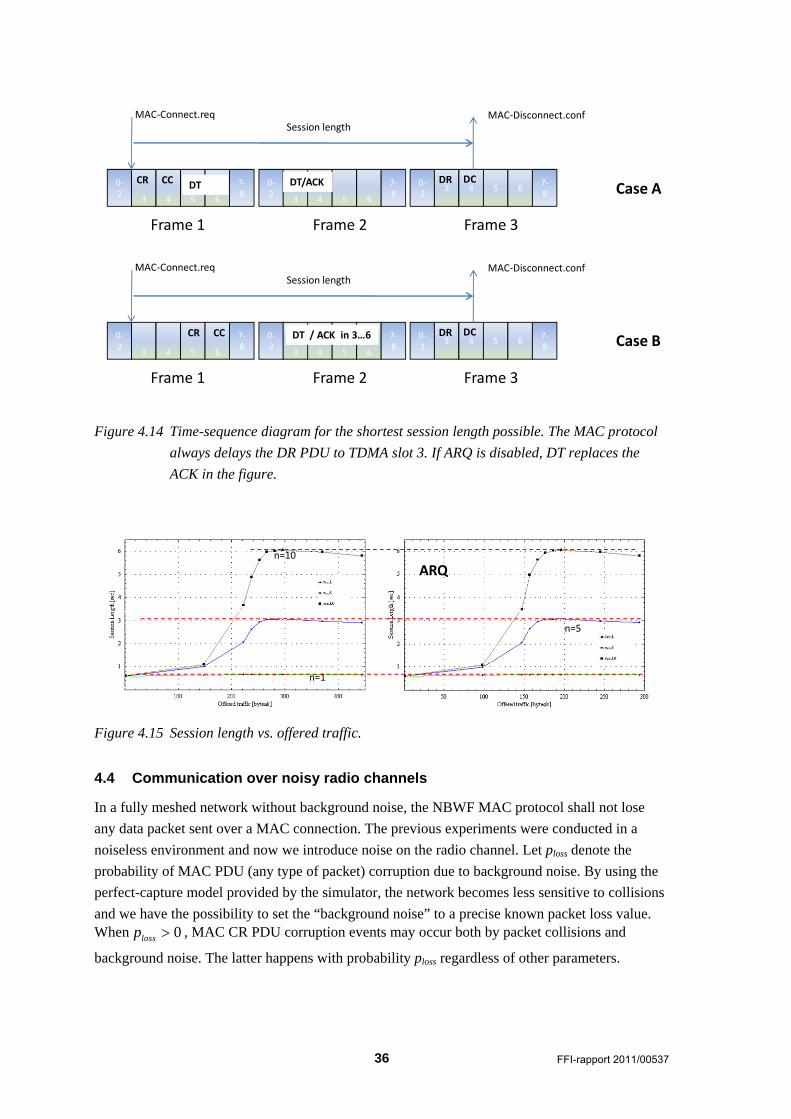
Figure 4.14 Time-sequence diagram for the shortest session length possible. The MAC protocol
always delays the DR PDU to TDMA slot 3. If ARQ is disabled, DT replaces the
ACK in the figure.
n=5
n=10
n=1
ARQ
Figure 4.15 Session length vs. offered traffic.
4.4 Communication over noisy radio channels
In a fully meshed network without background noise, the NBWF MAC protocol shall not lose
any data packet sent over a MAC connection. The previous experiments were conducted in a
noiseless environment and now we introduce noise on the radio channel. Let ploss denote the
probability of MAC PDU (any type of packet) corruption due to background noise. By using the
perfect-capture model provided by the simulator, the network becomes less sensitive to collisions
and we have the possibility to set the “background noise” to a precise known packet loss value. When 0lossp , MAC CR PDU corruption events may occur both by packet collisions and
background noise. The latter happens with probability ploss regardless of other parameters.
FFI-rapport 2011/00537 37
The MAC entity detects a MAC CR PDU loss event when the CC PDU expected does not arrive
at the known position in the TDM frame. Then MAC issues the same primitive (MAC-
Disconnect.indication) as if the node loses the channel access competition. If the MAC
connection setup phase fails, LLC continues later with the same LLC SDU until a MAC
connection is established, or the LLC SDU lifetime expires. In the latter case, the data packet is
deleted and LLC generates a MAC-Disconnect.request.
Data packets sent on a connection are only lost due to background noise in a fully meshed
network. In a network with hidden-nodes, the MAC reservation protocol may fail by accepting
two concurrent connections such that two nodes interfere when they send data packets. However,
this situation is an infrequent incident in a real network compared to the collision rate between
MAC CR PDUs.
Up to now we have used LLC SDU lengths much shorter than a typical IP packet. NBWF shall
handle each IP packet as one LLC SDU, that is, no segmentation of IP packets at layer 3a. This
section increases the packet length to embrace many TDM frames to indicate a more realistic IP
capacity. Remember that short LLC SDUs give lower efficiency than long ones.
When ARQ is enabled, loss of IP packets is either due to lifetime expiry, or buffer overflow in the
input buffer. These events occur only when the network operates close to saturation. The Layer 7
packet size is set to 148 9 98 1430 bytes. This packet size guarantees that all the data slots used usually are completely filled. When 0lossp , one LLC SDU occupies ca. ten consecutive
TDM frames where the last slot in the tenth frame carries the LLC ACK PDU.
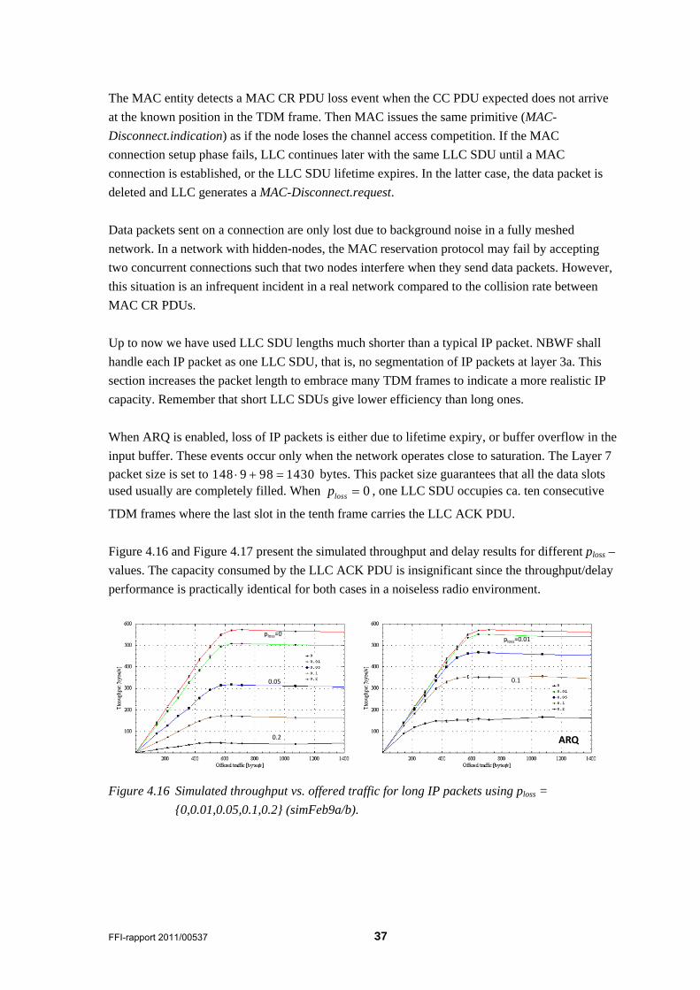
Figure 4.16 and Figure 4.17 present the simulated throughput and delay results for different ploss –
values. The capacity consumed by the LLC ACK PDU is insignificant since the throughput/delay
performance is practically identical for both cases in a noiseless radio environment.
ploss=0ploss=0.01
0.10.05
0.2 ARQ
Figure 4.16 Simulated throughput vs. offered traffic for long IP packets using ploss =
{0,0.01,0.05,0.1,0.2} (simFeb9a/b).
38 FFI-rapport 2011/00537
ARQ
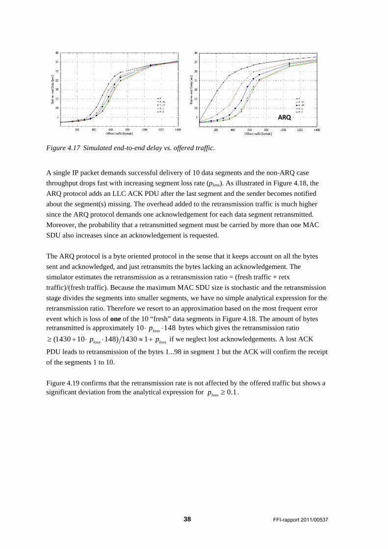
Figure 4.17 Simulated end-to-end delay vs. offered traffic.
A single IP packet demands successful delivery of 10 data segments and the non-ARQ case
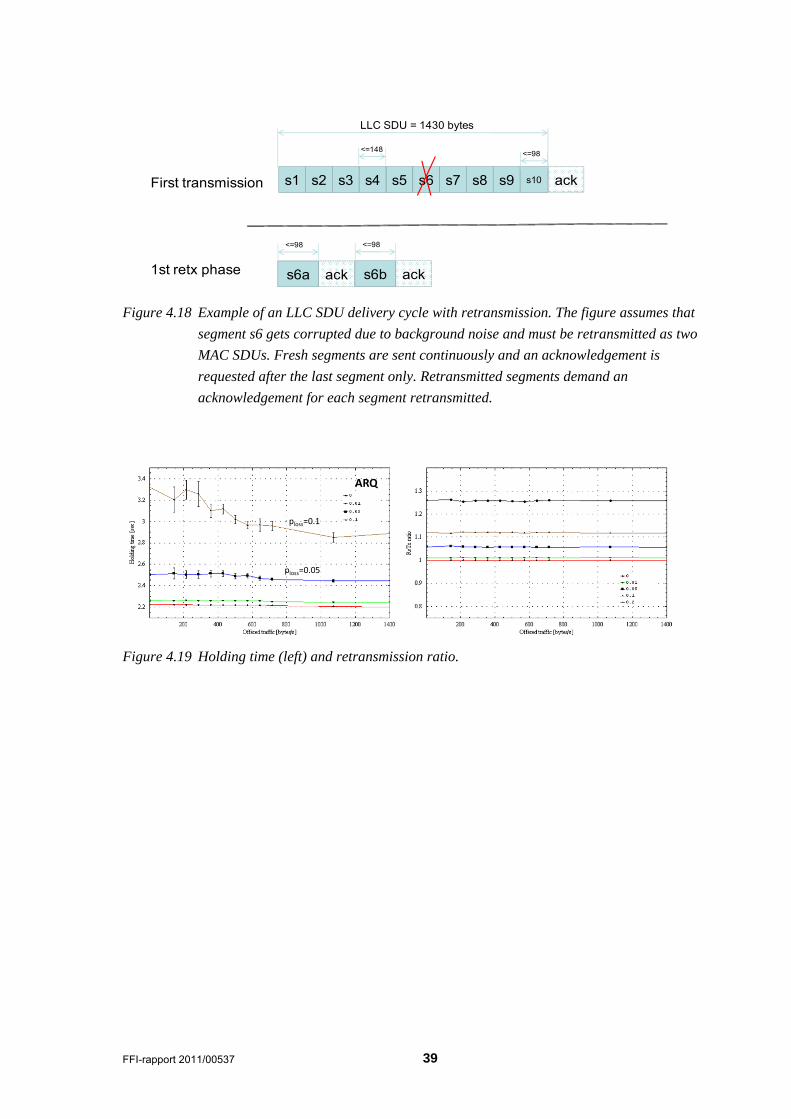
throughput drops fast with increasing segment loss rate (ploss). As illustrated in Figure 4.18, the
ARQ protocol adds an LLC ACK PDU after the last segment and the sender becomes notified
about the segment(s) missing. The overhead added to the retransmission traffic is much higher
since the ARQ protocol demands one acknowledgement for each data segment retransmitted.
Moreover, the probability that a retransmitted segment must be carried by more than one MAC
SDU also increases since an acknowledgement is requested.
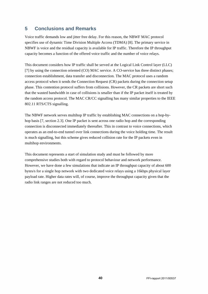
The ARQ protocol is a byte oriented protocol in the sense that it keeps account on all the bytes
sent and acknowledged, and just retransmits the bytes lacking an acknowledgement. The
simulator estimates the retransmission as a retransmission ratio = (fresh traffic + retx
traffic)/(fresh traffic). Because the maximum MAC SDU size is stochastic and the retransmission
stage divides the segments into smaller segments, we have no simple analytical expression for the
retransmission ratio. Therefore we resort to an approximation based on the most frequent error
event which is loss of one of the 10 “fresh” data segments in Figure 4.18. The amount of bytes retransmitted is approximately 10 148lossp bytes which gives the retransmission ratio
(1430 10 148) 1430 1loss lossp p if we neglect lost acknowledgements. A lost ACK
PDU leads to retransmission of the bytes 1...98 in segment 1 but the ACK will confirm the receipt
of the segments 1 to 10.
Figure 4.19 confirms that the retransmission rate is not affected by the offered traffic but shows a significant deviation from the analytical expression for 0.1lossp .
FFI-rapport 2011/00537 39
s10s1 s2
s6a
s5
ack
First transmission
1st retx phase
s3 s4 s6 s7 s8 s9 ack
<=148<=98
<=98
s6b ack
<=98
LLC SDU = 1430 bytes
Figure 4.18 Example of an LLC SDU delivery cycle with retransmission. The figure assumes that
segment s6 gets corrupted due to background noise and must be retransmitted as two
MAC SDUs. Fresh segments are sent continuously and an acknowledgement is
requested after the last segment only. Retransmitted segments demand an
acknowledgement for each segment retransmitted.
ploss=0.05
ARQ
ploss=0.1
Figure 4.19 Holding time (left) and retransmission ratio.
40 FFI-rapport 2011/00537
5 Conclusions and Remarks
Voice traffic demands low and jitter free delay. For this reason, the NBWF MAC protocol
specifies use of dynamic Time Division Multiple Access (TDMA) [8]. The primary service in
NBWF is voice and the residual capacity is available for IP traffic. Therefore the IP throughput
capacity becomes a function of the offered voice traffic and the number of voice relays.
This document considers how IP traffic shall be served at the Logical Link Control layer (LLC)
[7] by using the connection oriented (CO) MAC service. A CO-service has three distinct phases;
connection establishment, data transfer and disconnection. The MAC protocol uses a random
access protocol when it sends the Connection Request (CR) packets during the connection setup
phase. This contention protocol suffers from collisions. However, the CR packets are short such
that the wasted bandwidth in case of collisions is smaller than if the IP packet itself is treated by
the random access protocol. The MAC CR/CC signalling has many similar properties to the IEEE
802.11 RTS/CTS signalling.
The NBWF network serves multihop IP traffic by establishing MAC connections on a hop-by-
hop basis [7, section 2.3]. One IP packet is sent across one radio hop and the corresponding
connection is disconnected immediately thereafter. This in contrast to voice connections, which
operates as an end-to-end tunnel over link connections during the voice holding time. The result
is much signalling, but this scheme gives reduced collision rate for the IP packets even in
multihop environments.
This document represents a start of simulation study and must be followed by more
comprehensive studies both with regard to protocol behaviour and network performance.
However, we have done a few simulations that indicate an IP throughput capacity of about 600
bytes/s for a single hop network with two dedicated voice relays using a 16kbps physical layer
payload rate. Higher data rates will, of course, improve the throughput capacity given that the
radio link ranges are not reduced too much.
FFI-rapport 2011/00537 41
References
[1] “Requirements for a Narrowband Waveform”, AC/322(SC/6-AHWG/2)M(2008)0003,
August 2008.
[2] Open system interconnection – Basic reference model,
ISO/IEC 7498.
[3] Conventions for the definition of OSI Services,
ITU-T Recommendation X.210.
[4] OMNeT++, www.omnetpp.org
[5] Svein Haavik, ”Initial link layer protocol design for NBWF – input to NATO SC/6 –
AHWG/2”, FFI-rapport 2009/01895.
[6] Vivianne Jodalen, ”Modelling the NBWF radio”, TIPPER/FFI project document, FFI June
2008.
[7] Tore J Berg, “The design of an initial NBWF network simulator”, FFI-report 2008/01921,
FFI November 24th 2008.
[8] Bjørnar Libæk, et.al, “Enhancements to the Narrowband Waveform (NBWF) network
simulator”, FFI-report 2009/01765, FFI June 10th 2008.
[9] Bjørn Solberg, “Physical layer specification for the FFI NBWF OMNeT++ simulator”,
edition 2.0, Internal memo, FFI January 25th, 2009.
[10] Bjørnar Libæk and Bjørn Solberg, “A simulator model of the NATO Narrowband
Waveform physical layer”, FFI-notat 2011/00533, FFI October 19th, 2011.
42 FFI-rapport 2011/00537
Terms and Acronyms
AHA All hearing all
ARQ Automatic Repeat Request
CAS Carrier sense
CaP Capability Panel
CaT Capability Team
CC Connect Confirm
CC PDU Connect Confirm PDU
CCCH Common Control Channel
CEID Connection Endpoint Identifier
CL ConnectionLess
CNR Combat Net Radio
CO Connection Oriented
CODTC Connection oriented data traffic channel
CR Connect Request
CR PDU Connect Request PDU
CTS Clear To Send
DOM Document Object Model
DR-PDU Disconnect Request PDU
DSSS Direct Sequence Spread Spectrum
DT PDU Data PDU
FBN First Bit Number
GiD Global identifier
ICI Interface Control Information
IP Internet Protocol
IP-SAP Internet Protocol SAP
LBN Last Bit Number
LLC Logical Link Control
LLC-AM LLC Acknowledged Mode
LLCE LLC Entity
LLCP LLC Protocol
LLC-TM LLC Transparent Mode
LLC-UM LLC Unacknowledged Mode
MAC Medium Access Control
MACE MAC Entity
MAC-SP MAC Service Provider
MANET Mobile Ad-hoc NETwork
MIP-SAP Multicast IP SAP
MRATCH Multicast Random Access CHannel
MTCH one-to-Multipoint Traffic CHannel
MV Multicast Voice
MV-SAP Multicast Voice SAP
NBWF Narrow Band Wave Form
FFI-rapport 2011/00537 43
NC3B NATO C3 Board
NM-SAP Network Management SAP
OSI Open System Interconnection
OSI Open system
OTCH one-to-One Traffic CHannel
PCAS Premature CAS
PCI Protocol Control Information
PDP Packet Data Protocol
PDU Protocol Data Unit
PHY Physical
PTT Push To Talk
RATCH Random Access Traffic CHannel
RF Radio Frequency
RLC Radio Link Control
RM Reference Model
RRC Radio Resource Control
RTS Request To Send
SAP Service Access Point
SDU Service Data Unit
SNR Signal to Noise Ratio
SP Service Provider
SQL Structured Query Language
TDM Time Division Multiplexing
TDMA Time Division Multiple Access
UE User Environment or User Equipment
UTL Utility
UV Unicast Voice
UV-SAP Unicast Voice SAP
XML Extensible Mark-up Language
xxx-E xxx Entity (e.g., LLC-E)
xxx-SAP xxx Service Access Point (e.g., LLC-SAP)
xxx-SP xxx Service Provider (e.g. MAC-SP)


![SDR-Ready Standardized Waveforms for Tactical VHF and UHF ... · has consequently produced a draft standardization agreement (STANAG) for the NBWF physical layer [3], for the APIs,](https://img.pdfslide.us/doc/110x75/5f87422c50b5b82ab51e1614/sdr-ready-standardized-waveforms-for-tactical-vhf-and-uhf-has-consequently-produced.jpg)