Embed Size (px)
Citation preview
FFI-rapport 2009/01895
Initial link layer protocol design for NBWF – input to NATO SC/6 – AHWG/2
Svein Haavik
Norwegian Defence Research Establishment (FFI)
4 October 2011
2 FFI-rapport 2009/01895
FFI-rapport 2009/01895
1175
P: ISBN 978-82-464-1991-6
E: ISBN 978-82-464-1992-3
Keywords
Taktisk kommunikasjon
Trådløs kommunikasjon
Standardisering
Protokoll
Medium aksesskontroll
Approved by
Torunn Øvreås Project Manager
Eli Winjum Director of Research
Anders Eggen Director
FFI-rapport 2009/01895 3
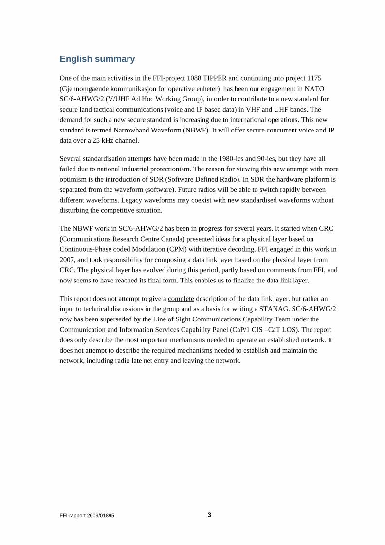
English summary
One of the main activities in the FFI-project 1088 TIPPER and continuing into project 1175
(Gjennomgående kommunikasjon for operative enheter) has been our engagement in NATO
SC/6-AHWG/2 (V/UHF Ad Hoc Working Group), in order to contribute to a new standard for
secure land tactical communications (voice and IP based data) in VHF and UHF bands. The
demand for such a new secure standard is increasing due to international operations. This new
standard is termed Narrowband Waveform (NBWF). It will offer secure concurrent voice and IP
data over a 25 kHz channel.
Several standardisation attempts have been made in the 1980-ies and 90-ies, but they have all
failed due to national industrial protectionism. The reason for viewing this new attempt with more
optimism is the introduction of SDR (Software Defined Radio). In SDR the hardware platform is
separated from the waveform (software). Future radios will be able to switch rapidly between
different waveforms. Legacy waveforms may coexist with new standardised waveforms without
disturbing the competitive situation.
The NBWF work in SC/6-AHWG/2 has been in progress for several years. It started when CRC
(Communications Research Centre Canada) presented ideas for a physical layer based on
Continuous-Phase coded Modulation (CPM) with iterative decoding. FFI engaged in this work in
2007, and took responsibility for composing a data link layer based on the physical layer from
CRC. The physical layer has evolved during this period, partly based on comments from FFI, and
now seems to have reached its final form. This enables us to finalize the data link layer.
This report does not attempt to give a complete description of the data link layer, but rather an
input to technical discussions in the group and as a basis for writing a STANAG. SC/6-AHWG/2
now has been superseded by the Line of Sight Communications Capability Team under the
Communication and Information Services Capability Panel (CaP/1 CIS –CaT LOS). The report
does only describe the most important mechanisms needed to operate an established network. It
does not attempt to describe the required mechanisms needed to establish and maintain the
network, including radio late net entry and leaving the network.
4 FFI-rapport 2009/01895
Sammendrag
En av hovedaktivitetene i prosjekt 1088 TIPPER og en delaktivitet i etterfølgende prosjekt 1175
(Gjennomgående kommunikasjon for operative enheter) har vært vårt engasjement i NATO SC/6-
AHWG/2 (V/UHF Ad Hoc Working Group), for å bidra til å utarbeide en ny standard for sikker
landtaktisk radiokommunikasjon (tale og IP-basert data) i VHF- og UHF-båndet. Behovet for en
ny sikker standard er stadig økende i f m internasjonale operasjoner. Den nye standarden går
under betegnelsen Narrowband Waveform (NBWF). Den skal tilby sikker samtidig tale og IP-
basert data over en kanal med 25 kHz båndbredde.
Det har vært gjort flere forsøk på slik standardisering på 1980 og 1990-tallet, men dette har
strandet p g a nasjonale industriinteresser. Grunnen til optimisme relatert til dette nye forsøket er
innføringen av SDR (Software Defined Radio). Med SDR skilles selve maskinplattformen i
radioen fra bølgeformen. Framtidige radioer vil være i stand til raskt å skifte mellom ulike
bølgeformer. Produsentenes egne bølgeformer kan derfor leve side om side med nye
standardiserte bølgeformer uten at konkurransesituasjonen forrykkes.
Arbeidet med NBWF i SC/6-AHWG/2 har pågått noen år. Det startet med at CRC
(Communications Research Centre Canada) presenterte ideer til et fysisk lag basert på
Continuous-Phase coded Modulation (CPM) med iterativ dekoding. FFI engasjerte seg i dette
arbeidet i 2007, og tok ansvaret med å utarbeide et datalinklag basert på CRCs fysiske lag. Etter
samarbeid med CRC ser fysisk lag nå ut til å nå sin endelige form, og dermed er den viktigste
forutsetningen for å ferdigstille datalinklaget kommet på plass.
Denne rapporten gir ikke en fullstendig beskrivelse av et datalinklag, men er ment som et
utgangspunkt for tekniske diskusjoner i NATO-gruppen og som et grunnlag for å utarbeide en
STANAG. SC/6-AHWG/2 er nå erstattet av et Line of Sight Communications Capability Team
under Communication and Information Services Capability Panel (CaP/1 CIS - CaT LOS).
Rapporten beskriver kun de viktigste mekanismene som trengs for å operere et etablert nettverk.
Den tar ikke sikte på å beskrive nødvendige mekanismer for å etablere og vedlikeholde nettverket
(drift og vedlikehold), inkludert det at radioer kommer inn i nettverket og forlater det.
FFI-rapport 2009/01895 5
Contents
1 Introduction 7
2 Choice of MAC Protocol 8
2.1 Background and requirements 8
2.2 Alternative MAC protocols 9
2.3 Preferences for the MAC protocol 9
3 Physical Layer 10
3.1 PHY modes and data rates 10
3.2 PHY structure 10
3.2.1 Problems to be addressed 11
3.2.2 PHY PCI 11
4 General Description of the Link Protocol 12
4.1 Encryption for COMSEC and traffic analysis 12
4.2 TDMA structure 15
4.3 Node addressing 16
4.4 Link layer control and data frames 16
4.5 Link layer services 17
5 Multicast Voice Service 18
5.1 MV reservation phase 19
5.2 MV release phase 22
5.3 Supplementary descriptions of the MV process 24
6 Unrestricted Voice and Data Services 26
7 IP data Services 27
7.1 The different transport services available to IP data 27
7.1.1 The fixed access transport service 28
7.1.2 The connectionless transport service 28
7.1.3 The connection-oriented transport service 28
7.1.4 Comparison of MAC transport services 29
7.2 IP Data Reservation contention 29
7.3 Unicast IP Data Reservation Process 32
7.4 Multicast IP Data Reservation Process 34
7.5 Radio silence (EMCON) 35
7.6 Segmentation 36
7.7 Selective repeat request ARQ protocol 37
6 FFI-rapport 2009/01895
7.8 Precedence and pre-emption of IP data services 39
7.8.1 Precedence and pre-emption within a node 39
7.8.2 Precedence and pre-emption in the network 42
7.9 Relaying and prioritized access 42
7.10 Selection of PHY mode (data rate) 42
7.11 IP Data Service without Reservation 43
7.11.1 IP data transmission without contention (in fixed slots) 43
7.11.2 IP data transmission with contention 43
8 Network Configuration Options 44
9 Protocol Control Information 44
9.1 Control frames related to multicast voice 48
9.2 Control frames related to general reservation 50
9.3 Link PCI of frames used for IP packet data 53
9.4 Selective ACK control frame 54
9.5 Link PCI of frames used for multicast voice service 56
9.6 Link PCI of frames used for unrestricted services 57
10 Functions omitted by the link layer 58
10.1 Packet buffering 59
10.2 Concatenation 59
10.3 Lifetime 59
11 Summary 60
Abbreviations 61
Bibliography 64
FFI-rapport 2009/01895 7
1 Introduction
Existing radios for land tactical communications in the VHF (30-88 MHz) and UHF (225-400
MHz) bands are based on a number of non-interoperable legacy waveforms. The current NATO
standards (STANAG 4204 and 4205) are not suitable for current and future use as they do not
support secure, simultaneous voice and packet switched data. An effort to produce a new standard
for NATO and partners has been the most important task of former NATO SC/6 – AHWG/2 and
will continue to be of the successor group. The new standard is termed Narrowband Waveform
(NBWF) as it is restricted to use the existing 25 kHz frequency slot allocations. The operational
requirements for NBWF are described in [1]. The final standard needs a number of contributions
such as physical layer, link layer, network layer, management and security. Major contributions
up to now have been on the physical and link layers only.
CRC by Phil Vigneron has proposed a physical layer (PHY) for NBWF [2], [7] . The PHY
waveform offers a number of data rates from 20 to 96 kbps within a bandwidth of 25 kHz. The
current proposal is based on a fixed frequency continuous-phase coded modulation (CPM) with
iterative decoding, while the final aim is also to produce an EPM resistant waveform based on a
frequency hopping mode using the same modulation principle.
FFI has taken on the task of proposing the link layer protocols for the NBWF. This document
aims at describing a first version of the link layer, and work as a discussion document and a
foundation for the standardisation of the link layer. It will have a number of unfinished items and
temporary values for many parameters. The work on a simulation model is in progress, but no
protocol feature has yet been verified by relevant simulations. Future simulation work will
support the finalization of the NBWF Link Layer STANAG.
The NBWF standard is supposed to end up in a number of variants. This document primarily
describes the land communications version, NBWF(L), with focus on the most challenging
aspects. This is considered to be in a network with simultaneous push-to-talk voice and data.
Other versions such as the air version, NBWF(A), have focus on low latency voice at the sacrifice
of data capacity. They can be constructed by minor modifications of what is presented in this
report. It is possible to construct a number of variants, serving any requirement from a pure voice
network, through a mixed voice and data network, to a pure data network.
A technical overview of the framework for the link layer design, based on FFI‟s interpretation of
the operational requirements, can be found in [3]. That document gives a more superior
introduction to the work of designing the NBWF link layer.
The (data) link layer is divided into two sublayers: Medium (or Media) Access Control (MAC)
and Logical Link Control (LLC). The main task of the MAC sublayer is to control access to the
physical transmission channel, which in our case is a common radio channel to be shared by all
links. LLC is responsible for reliable transfer of data blocks over the link.
8 FFI-rapport 2009/01895
2 Choice of MAC Protocol
One of the most important requirements [1] is that of Push-to-Talk voice with low delay (and
jitter). A MAC protocol based on contention cannot guarantee a low voice delay. For that reason,
a protocol based on Time Division is pursued.
2.1 Background and requirements
In order to select a suitable MAC protocol we must look at the requirements. The following
requirements and presumptions (mainly derived from [1] and knowledge of operations as of
today) are used as a basis for designing the MAC protocol:
A multi-hop network where a large fraction of nodes may be reached by a single hop
at the lowest data rate.
A significant fraction of the traffic is radio-broadcast1 or multicast (voice and data).
Voice is important and must be served with good QoS (short delay and small jitter).
Traffic consists of a mixture of predictable or streaming type and more random type
traffic.
An end-to-end voice delay of 500 ms is tolerated. We assume a 200 ms voice
buffering to be a proper choice.
Voice is primarily sent as MELPe [6] at 2,400 bps. Higher quality voice coders shall
be supported, but this is for future study.
Lowest data rate is 20 kbps – and this is the primary data rate unless the network is
set up with another rate as the lowest possible rate for a given operation. The lowest
data rate in normally used for all control traffic as that is considered to be the best
choice, see e.g. [8] .
We assume that the network has been established and describe an operational
network. We also assume that the synchronisation of the different nodes in the
network is such that a guard time of ~2 ms is sufficient as a maximum time
difference between any two nodes, including transmission delay. (Two nodes starting
their transmission “simultaneously” are received at any node with a time difference
< 2 ms.
Based on these requirements and presumptions we conclude that the MAC protocol needs to be
flexible, dynamic and supports QoS priority for voice.
1 Radio-broadcast is a service where information is broadcast once without any guarantee of delivery. Any
node within the ”radio range” will receive it.
FFI-rapport 2009/01895 9
2.2 Alternative MAC protocols
Carrier Sense Multiple Access (CSMA), probably the most popular MAC protocol (e.g. found in
IEEE 802.11 wireless LAN), is purely based on contention2. This works well for data where delay
requirements are not that stringent. For voice, where low delay and jitter is important this requires
a high capacity transmission channel and control of the network load in order to ensure a low
delay for the voice packets. Since NBWF has to operate down to a transmission rate of 20 kbps, a
purely contention-based MAC cannot guarantee the required QoS for voice.
Dynamic Time Division Multiple Access (D-TDMA) and soft reservation schemes such as
Collision Avoidance Time Allocation (CATA) [9] were identified in [4] and [5] as potential
solutions fulfilling most of the requirements. The main challenge, especially for CATA, is to limit
overhead due to signalling of control messages while at the same time fulfilling the requirements.
For our system, which operates at a very low Signal-To-Noise (SNR) ratio, the minimum
transmission time for a short signalling message is limited by the synchronization preamble. The
PHY has now been specified with a 3.6 ms total duration for the preamble [2] . Theoretical
calculations will show that this may not be reduced significantly without sacrificing noise
performance. A CATA scheme where the control mini-slots are at least 4 ms will be extremely
inefficient in combination with a 200 ms frame length (due to voice delay requirement). Thus, we
are left with a dynamic TDMA system as the only relevant alternative.
2.3 Preferences for the MAC protocol
Even though the conclusion is to use a dynamic TDMA protocol, there are many variants with a
number of details to specify. The prime reason for using TDMA is to support QoS for voice
services, through a separate logical channel for voice. Several existing radio systems use this kind
of channel sharing between voice and data, with a fixed voice allocation. This is not TDMA but
more like TDM (Time Division Multiplexing) which is less dynamic or flexible. We intend to
apply a flexible resource allocation for voice, allowing more of the total capacity to be used for
data whenever the voice channel is inactive.
It is possible to apply a split channel scheme for voice and data through TDMA, but still using a
contention protocol for the data channel. For a multi-hop network with large data packets (long
transmission time) it might be preferable to use a reservation protocol for data. Our intention is to
support reservation for data, where the reservation itself is exposed to contention, but later we
will study the performance compared to a pure contention protocol. The final specification will
most probably describe a combination of the two, where reservation is used for long
transmissions and contention for short ones.
2 IEEE 802.11 does specify some mechanisms that involve reservation, but they are not in common use.
10 FFI-rapport 2009/01895
3 Physical Layer
This chapter gives a short description of the physical layer which serves as a basis for designing
the link layer. Only aspects that are important for MAC and LLC are explained. For a complete
description of the NBWF physical layer, the reader is referred to [2] .
3.1 PHY modes and data rates
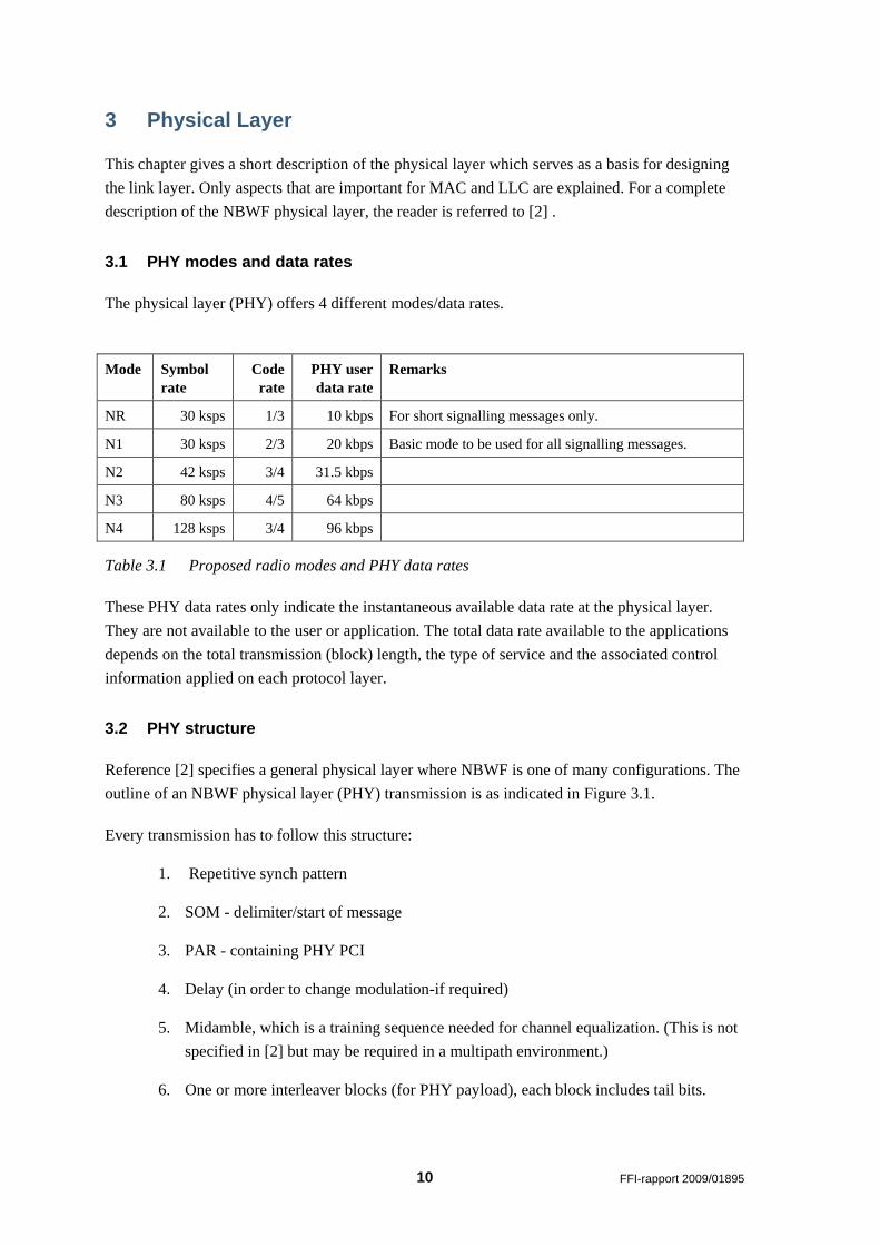
The physical layer (PHY) offers 4 different modes/data rates.
Mode Symbol
rate
Code
rate
PHY user
data rate
Remarks
NR 30 ksps 1/3 10 kbps For short signalling messages only.
N1 30 ksps 2/3 20 kbps Basic mode to be used for all signalling messages.
N2 42 ksps 3/4 31.5 kbps
N3 80 ksps 4/5 64 kbps
N4 128 ksps 3/4 96 kbps
Table 3.1 Proposed radio modes and PHY data rates
These PHY data rates only indicate the instantaneous available data rate at the physical layer.
They are not available to the user or application. The total data rate available to the applications
depends on the total transmission (block) length, the type of service and the associated control
information applied on each protocol layer.
3.2 PHY structure
Reference [2] specifies a general physical layer where NBWF is one of many configurations. The
outline of an NBWF physical layer (PHY) transmission is as indicated in Figure 3.1.
Every transmission has to follow this structure:
1. Repetitive synch pattern
2. SOM - delimiter/start of message
3. PAR - containing PHY PCI
4. Delay (in order to change modulation-if required)
5. Midamble, which is a training sequence needed for channel equalization. (This is not
specified in [2] but may be required in a multipath environment.)
6. One or more interleaver blocks (for PHY payload), each block includes tail bits.
FFI-rapport 2009/01895 11
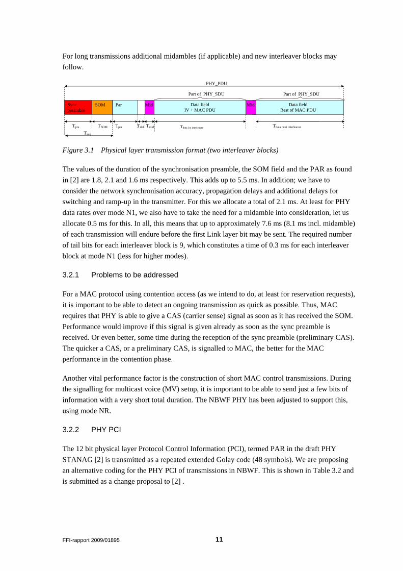
For long transmissions additional midambles (if applicable) and new interleaver blocks may
follow.
Tpre
Tacq
Tdata 1st interleaver
Data field
Rest of MAC PDU
Tdata next interleaver
Mid Data field
IV + MAC PDU
Tmid
Mid
PHY_PDU
Part of PHY_SDU Part of PHY_SDU
Sync
preamble
SOM Par
Tpar
Tdel TSOM
Figure 3.1 Physical layer transmission format (two interleaver blocks)
The values of the duration of the synchronisation preamble, the SOM field and the PAR as found
in [2] are 1.8, 2.1 and 1.6 ms respectively. This adds up to 5.5 ms. In addition; we have to
consider the network synchronisation accuracy, propagation delays and additional delays for
switching and ramp-up in the transmitter. For this we allocate a total of 2.1 ms. At least for PHY
data rates over mode N1, we also have to take the need for a midamble into consideration, let us
allocate 0.5 ms for this. In all, this means that up to approximately 7.6 ms (8.1 ms incl. midamble)
of each transmission will endure before the first Link layer bit may be sent. The required number
of tail bits for each interleaver block is 9, which constitutes a time of 0.3 ms for each interleaver
block at mode N1 (less for higher modes).
3.2.1 Problems to be addressed
For a MAC protocol using contention access (as we intend to do, at least for reservation requests),
it is important to be able to detect an ongoing transmission as quick as possible. Thus, MAC
requires that PHY is able to give a CAS (carrier sense) signal as soon as it has received the SOM.
Performance would improve if this signal is given already as soon as the sync preamble is
received. Or even better, some time during the reception of the sync preamble (preliminary CAS).
The quicker a CAS, or a preliminary CAS, is signalled to MAC, the better for the MAC
performance in the contention phase.
Another vital performance factor is the construction of short MAC control transmissions. During
the signalling for multicast voice (MV) setup, it is important to be able to send just a few bits of
information with a very short total duration. The NBWF PHY has been adjusted to support this,
using mode NR.
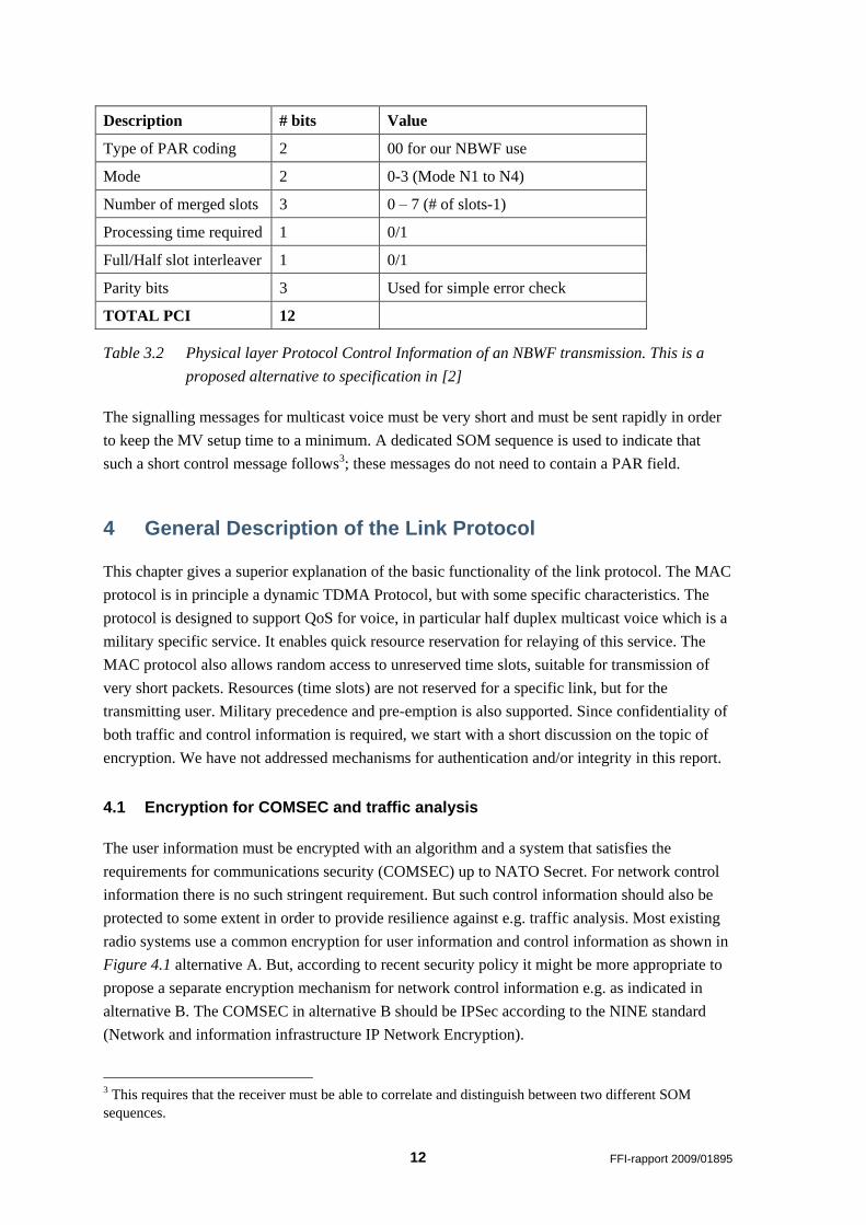
3.2.2 PHY PCI
The 12 bit physical layer Protocol Control Information (PCI), termed PAR in the draft PHY
STANAG [2] is transmitted as a repeated extended Golay code (48 symbols). We are proposing
an alternative coding for the PHY PCI of transmissions in NBWF. This is shown in Table 3.2 and
is submitted as a change proposal to [2] .
12 FFI-rapport 2009/01895
Description # bits Value
Type of PAR coding 2 00 for our NBWF use
Mode 2 0-3 (Mode N1 to N4)
Number of merged slots 3 0 – 7 (# of slots-1)
Processing time required 1 0/1
Full/Half slot interleaver 1 0/1
Parity bits 3 Used for simple error check
TOTAL PCI 12
Table 3.2 Physical layer Protocol Control Information of an NBWF transmission. This is a
proposed alternative to specification in [2]
The signalling messages for multicast voice must be very short and must be sent rapidly in order
to keep the MV setup time to a minimum. A dedicated SOM sequence is used to indicate that
such a short control message follows3; these messages do not need to contain a PAR field.
4 General Description of the Link Protocol
This chapter gives a superior explanation of the basic functionality of the link protocol. The MAC
protocol is in principle a dynamic TDMA Protocol, but with some specific characteristics. The
protocol is designed to support QoS for voice, in particular half duplex multicast voice which is a
military specific service. It enables quick resource reservation for relaying of this service. The
MAC protocol also allows random access to unreserved time slots, suitable for transmission of
very short packets. Resources (time slots) are not reserved for a specific link, but for the
transmitting user. Military precedence and pre-emption is also supported. Since confidentiality of
both traffic and control information is required, we start with a short discussion on the topic of
encryption. We have not addressed mechanisms for authentication and/or integrity in this report.
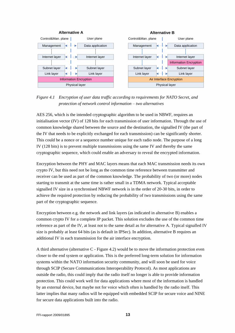
4.1 Encryption for COMSEC and traffic analysis
The user information must be encrypted with an algorithm and a system that satisfies the
requirements for communications security (COMSEC) up to NATO Secret. For network control
information there is no such stringent requirement. But such control information should also be
protected to some extent in order to provide resilience against e.g. traffic analysis. Most existing
radio systems use a common encryption for user information and control information as shown in
Figure 4.1 alternative A. But, according to recent security policy it might be more appropriate to
propose a separate encryption mechanism for network control information e.g. as indicated in
alternative B. The COMSEC in alternative B should be IPSec according to the NINE standard
(Network and information infrastructure IP Network Encryption).
3 This requires that the receiver must be able to correlate and distinguish between two different SOM
sequences.
FFI-rapport 2009/01895 13
Management
Control&Man. plane User plane
Subnet layer
Link layer
Physical layer
Information Encryption
Alternative A
Management
Control&Man. plane User plane
Data application
Internet layer
Link layer
Air Interface Encryption
Physical layer
Internet layer
Link layer
Information Encryption
Alternative B
Internet layer
Data application
Link layer
Internet layer
Subnet layer Subnet layer Subnet layer
Figure 4.1 Encryption of user data traffic according to requirements for NATO Secret, and
protection of network control information – two alternatives
AES 256, which is the intended cryptographic algorithm to be used in NBWF, requires an
initialisation vector (IV) of 128 bits for each transmission of user information. Through the use of
common knowledge shared between the source and the destination, the signalled IV (the part of
the IV that needs to be explicitly exchanged for each transmission) can be significantly shorter.
This could be a nonce or a sequence number unique for each radio node. The purpose of a long
IV (128 bits) is to prevent multiple transmissions using the same IV and thereby the same
cryptographic sequence, which could enable an adversary to reveal the encrypted information.
Encryption between the PHY and MAC layers means that each MAC transmission needs its own
crypto IV, but this need not be long as the common time reference between transmitter and
receiver can be used as part of the common knowledge. The probability of two (or more) nodes
starting to transmit at the same time is rather small in a TDMA network. Typical acceptable
signalled IV size in a synchronised NBWF network is in the order of 20-30 bits, in order to
achieve the required protection by reducing the probability of two transmissions using the same
part of the cryptographic sequence.
Encryption between e.g. the network and link layers (as indicated in alternative B) enables a
common crypto IV for a complete IP packet. This solution excludes the use of the common time
reference as part of the IV, at least not to the same detail as for alternative A. Typical signalled IV
size is probably at least 64 bits (as is default in IPSec). In addition, alternative B requires an
additional IV in each transmission for the air interface encryption.
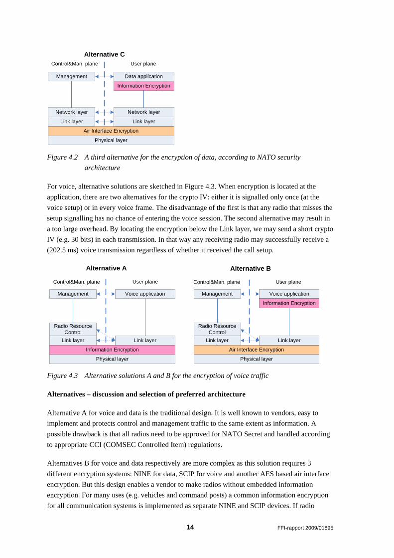
A third alternative (alternative C - Figure 4.2) would be to move the information protection even
closer to the end system or application. This is the preferred long-term solution for information
systems within the NATO information security community, and will soon be used for voice
through SCIP (Secure Communications Interoperability Protocol). As most applications are
outside the radio, this could imply that the radio itself no longer is able to provide information
protection. This could work well for data applications where most of the information is handled
by an external device, but maybe not for voice which often is handled by the radio itself. This
latter implies that many radios will be equipped with embedded SCIP for secure voice and NINE
for secure data applications built into the radio.
14 FFI-rapport 2009/01895
Management
Control&Man. plane User plane
Data application
Network layer
Link layer
Air Interface Encryption
Network layer
Link layer
Information Encryption
Physical layer
Alternative C
Figure 4.2 A third alternative for the encryption of data, according to NATO security
architecture
For voice, alternative solutions are sketched in Figure 4.3. When encryption is located at the
application, there are two alternatives for the crypto IV: either it is signalled only once (at the
voice setup) or in every voice frame. The disadvantage of the first is that any radio that misses the
setup signalling has no chance of entering the voice session. The second alternative may result in
a too large overhead. By locating the encryption below the Link layer, we may send a short crypto
IV (e.g. 30 bits) in each transmission. In that way any receiving radio may successfully receive a
(202.5 ms) voice transmission regardless of whether it received the call setup.
Management
Control&Man. plane User plane
Voice application
Radio Resource
Control
Link layer
Physical layer
Link layer
Management
Control&Man. plane User plane
Voice application
Radio Resource
Control
Link layer
Air Interface Encryption
Physical layer
Link layer
Information Encryption
Information Encryption
Alternative A Alternative B
Figure 4.3 Alternative solutions A and B for the encryption of voice traffic
Alternatives – discussion and selection of preferred architecture
Alternative A for voice and data is the traditional design. It is well known to vendors, easy to
implement and protects control and management traffic to the same extent as information. A
possible drawback is that all radios need to be approved for NATO Secret and handled according
to appropriate CCI (COMSEC Controlled Item) regulations.
Alternatives B for voice and data respectively are more complex as this solution requires 3
different encryption systems: NINE for data, SCIP for voice and another AES based air interface
encryption. But this design enables a vendor to make radios without embedded information
encryption. For many uses (e.g. vehicles and command posts) a common information encryption
for all communication systems is implemented as separate NINE and SCIP devices. If radio
FFI-rapport 2009/01895 15
internal protocols do not need the same level of protection as NATO secret information, less
stringent rules for approval and handling of such radios may apply.
Alternative C for data, where information encryption is located closer to the end-users, is
architecturally very similar to alternative B for voice. For the radio design, alternatives B (both
voice and data) and C are similar in the sense that information encryption no longer is part of the
radio standard. Alternative C for data might be relevant in the future if e.g. SCIP is used also for
end-to-end data information protection.
The preferred architecture for NBWF is to leave COMSEC out of the NBWF specification, but
refer to the use of NINE and SCIP for protection of information up to NATO Secret. NBWF will
include an Air Interface Encryption, which is primarily intended for confidentiality protection of
radio control traffic. However, it is considered advantageous to require that all NBWF
implementations should allow this encryption to be approved for confidentiality protection of
information up to NATO Restricted. Higher classified information must be protected by the use
of NINE and SCIP, which both can be external devices or embedded in the radio
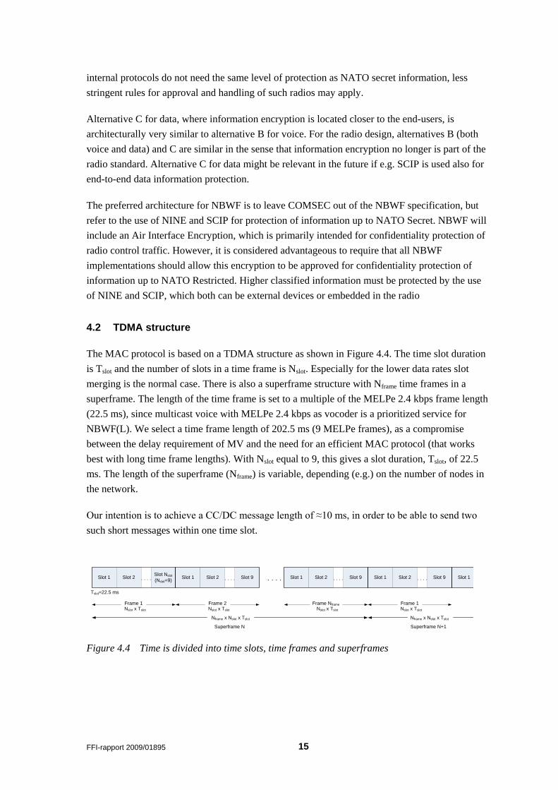
4.2 TDMA structure
The MAC protocol is based on a TDMA structure as shown in Figure 4.4. The time slot duration
is Tslot and the number of slots in a time frame is Nslot. Especially for the lower data rates slot
merging is the normal case. There is also a superframe structure with Nframe time frames in a
superframe. The length of the time frame is set to a multiple of the MELPe 2.4 kbps frame length
(22.5 ms), since multicast voice with MELPe 2.4 kbps as vocoder is a prioritized service for
NBWF(L). We select a time frame length of 202.5 ms (9 MELPe frames), as a compromise
between the delay requirement of MV and the need for an efficient MAC protocol (that works
best with long time frame lengths). With Nslot equal to 9, this gives a slot duration, Tslot, of 22.5
ms. The length of the superframe (Nframe) is variable, depending (e.g.) on the number of nodes in
the network.
Our intention is to achieve a CC/DC message length of ≈10 ms, in order to be able to send two
such short messages within one time slot.
Slot 1 Slot 2Slot Nslot
(Nslot=9)
Tslot=22.5 ms
. . . . Slot 1 Slot 2 Slot 9. . . . . . . . Slot 1 Slot 2 Slot 9. . . . Slot 1 Slot 2 Slot 9. . . .
Superframe N
Nframe x Nslot x Tslot
Superframe N+1
Nframe x Nslot x Tslot
Slot 1
Frame 1Nslot x Tslot
Frame 2Nslot x Tslot
Frame Nframe
Nslot x Tslot
Frame 1Nslot x Tslot
Figure 4.4 Time is divided into time slots, time frames and superframes
16 FFI-rapport 2009/01895
We define 4 different types of time slots:
• Superframe slots: these slots are reserved on a (relative) fixed basis and are allocated to the
network nodes through the superframe structure
• Multicast voice slots: these slots are allocated for multicast voice (or MV signalling) only
• Dual-use slots: these slots may be reserved and allocated to a node for voice or data, but
when used for data they are exposed to pre-emption from any node involved in an MV setup.
• General slots: may be reserved and allocated to a node for a certain time.
In this first description for NBWF(L) we only consider mode N1 (20 kbps) and use a regular
scheme with a time slot duration of 22.25 ms and 9 slots in each time frame (202.5 ms). The
length of the superframe is set at network establishment, and may be adjusted later by a network
management process (not described here). The superframe slots may be used to allocate a fixed
data capacity to each node in the network, while the general slots are used to allocate dynamic
data capacity to the nodes depending on their prevailing demands.
4.3 Node addressing
We assume that 8 bits is enough to uniquely define a node‟s address. The requirements [1] claim
up to 256 nodes in a network, but that is not very likely or useful. Node addresses are only local
addresses, unique within a subnet. They are dynamically assigned by the network, at network
establishment or late net entry.
Node addresses 0 and 255 are reserved numbers; 0 is used to indicate “no node” or the end of a
list of nodes. Node address 255 should be used for radio broadcast. That means that any node
receiving a transmission destined for node address 255 should treat that as a transmission destined
for it self. Node addresses from 1 to some number Nmax should be used for individual node
addressing, while addresses from Nmax+1 to 254 are used to identify multicast groups. Multicast
groups must be defined before use through the management system. They may be predefined
before deployment or through user intervention during network operation. These management
mechanisms are not described in this document.
4.4 Link layer control and data frames
There are three different categories of link frames (also termed Protocol Data Unit (PDU) in the
OSI reference model terminology):
Control PDUs are generated by the link layer and contain no payload.
Data PDUs are generated by the link layer on action from NET and contain user data.
These frames are used for data transmission in an established TDMA network.
FFI-rapport 2009/01895 17
Management PDUs are used e.g. in the process of establishing a network, that is
when no TDMA frame structure is established. These frames are not used in this
document as it only addresses the operation of an already established network.
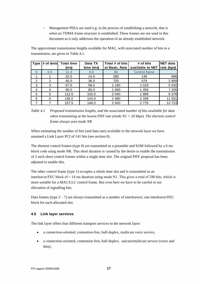
The approximate transmission lengths available for MAC, with associated number of bits in a
transmission, are given in Table 4.1.
Table 4.1 Proposed transmission lengths, and the associated number of bits available for data
when transmitting at the lowest PHY rate (mode N1 = 20 kbps). The shortest control
frame always uses mode NR
When estimating the number of bits (and data rate) available to the network layer we have
assumed a Link Layer PCI of 141 bits (see section 0).
The shortest control frames (type 0) are transmitted as a preamble and SOM followed by a 6 ms
block code using mode NR. This short duration is caused by the desire to enable the transmission
of 2 such short control frames within a single time slot. The original PHY proposal has been
adjusted to enable this.
The other control frame (type 1) occupies a whole time slot and is transmitted as an
interleaver/FEC block of ≈ 14 ms duration using mode N1. This gives a total of 280 bits, which is
more suitable for a MAC/LLC control frame. But even here we have to be careful in our
allocation of signalling bits.
Data frames (type 2 – 7) are always transmitted as a number of interleavers; one interleaver/FEC
block for each allocated slot.
4.5 Link layer services
The link layer offers four different transport services to the network layer:
a connection-oriented, contention-free, half-duplex, multicast voice service,
a connection-oriented, contention-free, half-duplex, unicast/multicast service (voice and
data),
Type # of slots Total time Data TX Total # of bits # of bits NET data
(ms) time (ms) at Basic_Rate available to NET rate (bps)
0 0.5 11.3 6.0 60 Control frame
1 1 22.5 14.0 280 139 686
2 2 45.0 36.0 720 579 2 859
3 3 67.5 58.0 1 160 1 019 5 032
4 4 90.0 80.0 1 600 1 459 7 205
5 5 112.5 102.0 2 040 1 899 9 378
6 6 135.0 124.0 2 480 2 339 11 551
7 7 157.5 146.0 2 920 2 779 13 723
18 FFI-rapport 2009/01895
a connectionless, contention-free, unicast/multicast IP data service that uses fixed
allocated time slots and
a connectionless unicast/multicast IP data service4 based on contention access.
The multicast voice service uses reserved time slots, and offers pre-emption of data whenever
required. Relaying of MV is also performed by the link layer and the required number of dual-use
time slots will be reserved for the relaying. The dual-use time slots remain reserved for MV (by
any node) for a certain period (e.g. 10 s) after termination of the MV session (when PTT is
released). This is due to the high probability of a response from one of the receivers.
The need for a half-duplex unicast/multicast service is not defined in the requirements [1] , but
is a service with many similarities to MV. For this reason, it should be easy to implement. In
addition, future NBWF users may want a selective call service. This service may be used for
transport of voice using e.g. MELPe or for the transport of unrestricted/transparent data. The
latter application is frequently used today, but may be less required in the future when all services
are transported over IP.
The contention-free IP data service uses superframe slots that are reserved for the node. This
means that there is no contention using this service. There may be special restrictions on payload
size for this service as segmentation (see section 7.6 for details) might not be supported for this
service. The maximum length of a transmission is limited by the number of superframe slots that
are allocated in the TDMA structure (see section 4.2).
The contention-based IP data service is able to exploit both general time slots and dual-use time
slots. This service can use both a connection-oriented and a connectionless MAC service. A node
with data to transmit using the connection-oriented MAC service shall try to reserve as many time
slots as possible. This normally includes dual-use time slots that are exposed to pre-emption by
multicast voice. When pre-empted by MV, the node shall give up the requested number of dual-
use time slots, but may continue to use the general time slots. When the MV session is
terminated, the dual-use time slots are not automatically available for use by the pre-empted node
(data user), but must be reserved by any node through contention. Each network SDU (IP packet)
from the network layer is mapped on to one LLC PDU. When using the connectionless MAC
service without slot reservation, a restriction on IP payload size may apply (e.g. 50 – 100 bytes).
5 Multicast Voice Service
In each time frame, at least one time slot is always reserved for multicast voice, which is a
simplex service from one to many. These MV slots are always selected consecutively from the
first slot and upwards. In general, MV signalling reserves permanently one time slot for each MV
channel, plus one additional time slot for each relay allowed in the network (in order to obtain an
4 Depending on QoS parameters signaled from NET and payload size, LLC addresses two different MAC
services: connection-oriented and connectionless.
FFI-rapport 2009/01895 19
acceptable connection setup time). MV transfer using the default vocoder (MELPe at 2.4 kbps)
requires two time slots in each frame at the two lowest rate PHY modes. This means that for each
MV session there must be a reservation process before the MV can be transmitted. In case of
relays, each additional relay requires the same resources as the originator. In the first version of
the specification, only preconfigured relays are supported. The final objective is to be able to
support dynamical relay selection, but the network has a restriction on the maximum number of
relays allowed.
5.1 MV reservation phase
A multicast voice transfer is always preceded by a reservation phase. The originator, when
triggered by a PTT (Push-To-Talk), shall transmit a Multicast Voice Connect Request (MCR) in
the first available reserved MV slot. The originator shall determine which node(s) to be used for
relaying, if that is required, and which additional nodes to assist in the reservation process. The
relay will implicitly confirm the reservation in its own CR. Any other assisting node will confirm
the reservation by transmitting an explicit Multicast Voice Connect Confirm (MCC).
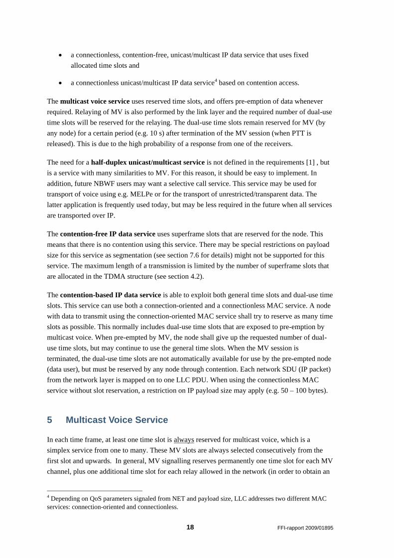
The purpose of the MCC is both to confirm that there is no reservation conflict and also to inform
the CC node‟s own neighbours about the reservation, preventing them from disturbing the
reception (see Figure 5.1). The choice of CC nodes should be done so as to reach as many
neighbours as possible to each of the nodes contained in the MV multicast group. Relay nodes are
always selected as CC nodes, using implicit MCC (piggybacked on the relay node‟s own MCR).
When the MCR and all MCCs are transmitted, any node that holds a reservation of any Dual Use
slot is pre-empted, and the DU slot(s) are reallocated for MV transmission. The reserved data
connection can still continue to use its GU slots.
Origin MCRCC-
node
MCC
Possible
Disturber
Figure 5.1 Two-hop neighbours from the transmitting node may disturb the reception in one or
more nodes. They do not hear the MV Connect Request, and must be informed
through an MV Connect Confirm
20 FFI-rapport 2009/01895
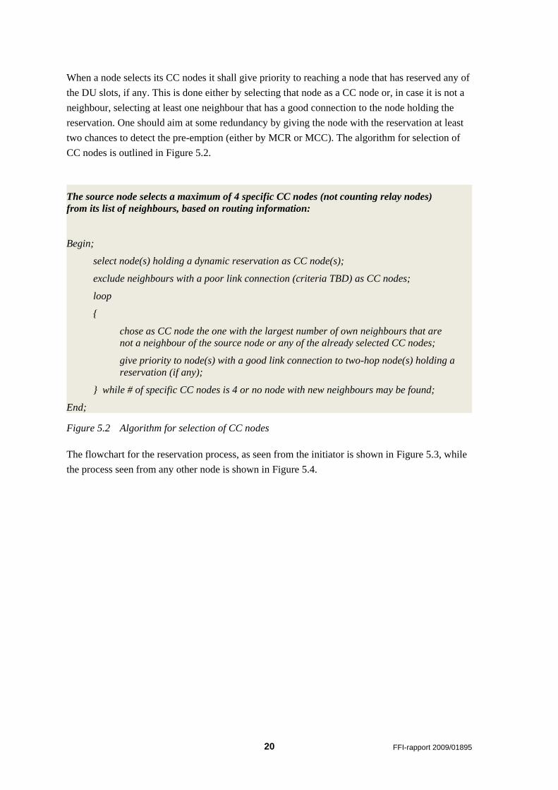
When a node selects its CC nodes it shall give priority to reaching a node that has reserved any of
the DU slots, if any. This is done either by selecting that node as a CC node or, in case it is not a
neighbour, selecting at least one neighbour that has a good connection to the node holding the
reservation. One should aim at some redundancy by giving the node with the reservation at least
two chances to detect the pre-emption (either by MCR or MCC). The algorithm for selection of
CC nodes is outlined in Figure 5.2.
Figure 5.2 Algorithm for selection of CC nodes
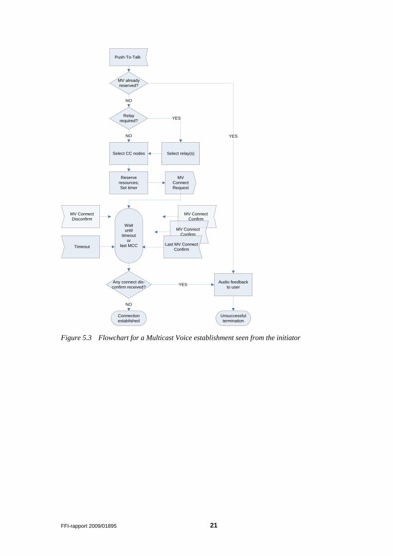
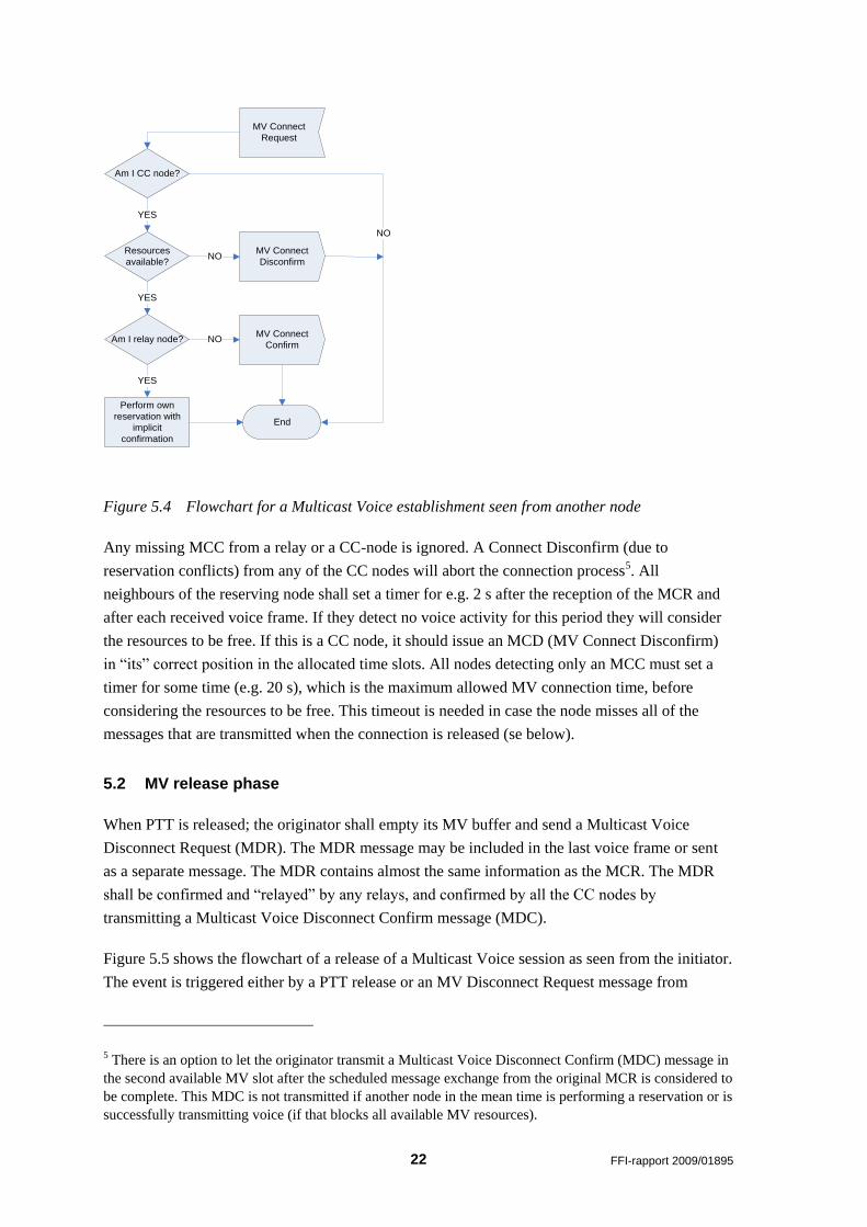
The flowchart for the reservation process, as seen from the initiator is shown in Figure 5.3, while
the process seen from any other node is shown in Figure 5.4.
The source node selects a maximum of 4 specific CC nodes (not counting relay nodes)
from its list of neighbours, based on routing information:
Begin;
select node(s) holding a dynamic reservation as CC node(s);
exclude neighbours with a poor link connection (criteria TBD) as CC nodes;
loop
{
chose as CC node the one with the largest number of own neighbours that are
not a neighbour of the source node or any of the already selected CC nodes;
give priority to node(s) with a good link connection to two-hop node(s) holding a
reservation (if any);
} while # of specific CC nodes is 4 or no node with new neighbours may be found;
End;
FFI-rapport 2009/01895 21
MV Connect
Confirm
Select relay(s)
MV already
reserved?
Audio feedback
to user
YES
NO
Relay
required?YES
Reserve
resources;
Set timer
NO
Select CC nodes
Any connect dis-
confirm received?YES
NO
Unsuccessful
termination
Connection
established
Push-To-Talk
Wait
until
timeout
or
last MCC
MV
Connect
Request
Timeout
MV Connect
Confirm
Last MV Connect
Confirm
MV Connect
Disconfirm
Figure 5.3 Flowchart for a Multicast Voice establishment seen from the initiator
22 FFI-rapport 2009/01895
Perform own
reservation with
implicit
confirmation
Resources
available?NO
YES
Am I relay node?
End
Am I CC node?
YES
NO
YES
NO
MV Connect
Request
MV Connect
Disconfirm
MV Connect
Confirm
Figure 5.4 Flowchart for a Multicast Voice establishment seen from another node
Any missing MCC from a relay or a CC-node is ignored. A Connect Disconfirm (due to
reservation conflicts) from any of the CC nodes will abort the connection process5. All
neighbours of the reserving node shall set a timer for e.g. 2 s after the reception of the MCR and
after each received voice frame. If they detect no voice activity for this period they will consider
the resources to be free. If this is a CC node, it should issue an MCD (MV Connect Disconfirm)
in “its” correct position in the allocated time slots. All nodes detecting only an MCC must set a
timer for some time (e.g. 20 s), which is the maximum allowed MV connection time, before
considering the resources to be free. This timeout is needed in case the node misses all of the
messages that are transmitted when the connection is released (se below).
5.2 MV release phase
When PTT is released; the originator shall empty its MV buffer and send a Multicast Voice
Disconnect Request (MDR). The MDR message may be included in the last voice frame or sent
as a separate message. The MDR contains almost the same information as the MCR. The MDR
shall be confirmed and “relayed” by any relays, and confirmed by all the CC nodes by
transmitting a Multicast Voice Disconnect Confirm message (MDC).
Figure 5.5 shows the flowchart of a release of a Multicast Voice session as seen from the initiator.
The event is triggered either by a PTT release or an MV Disconnect Request message from
5 There is an option to let the originator transmit a Multicast Voice Disconnect Confirm (MDC) message in
the second available MV slot after the scheduled message exchange from the original MCR is considered to
be complete. This MDC is not transmitted if another node in the mean time is performing a reservation or is
successfully transmitting voice (if that blocks all available MV resources).

FFI-rapport 2009/01895 23
another node. The latter may be the result of an MV pre-emption, caused by the initiation of a
higher priority MV session. MV pre-emption is not described in this report. Figure 5.6 shows the
associated flowchart seen from another node.
MV Disconnect
Request
MV
Disconnect
Request
End
MV Disconnect
Confirm
Set timer
MV Disconnect
Confirm
Timeout
PTT released
Wait
until
timeout
or
last MDC Last MV
Disconnect
Confirm
Figure 5.5 Flowchart for a Multicast Voice connection release seen from initiator
Perform own
resource release
with implicit
confirmation
Am I relay node?
End
Am I CC node?
YES NO
YES
NO
MV Disconnect
Request
MV
Disconnect
Confirmation
Figure 5.6 Flowchart for a Multicast Voice connection release seen from another node
24 FFI-rapport 2009/01895
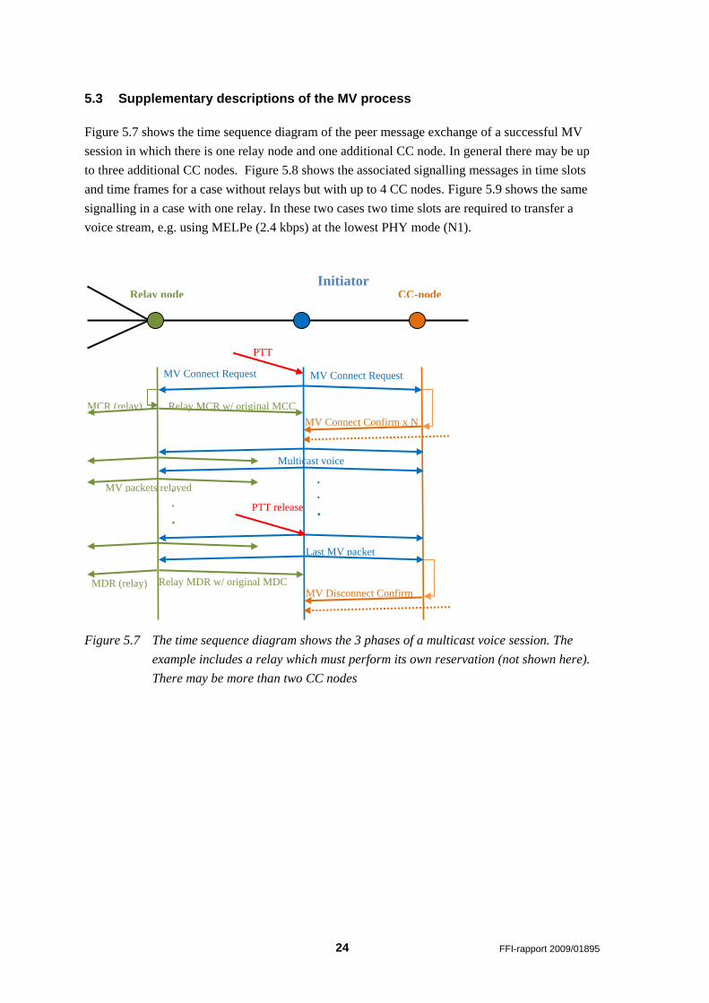
5.3 Supplementary descriptions of the MV process
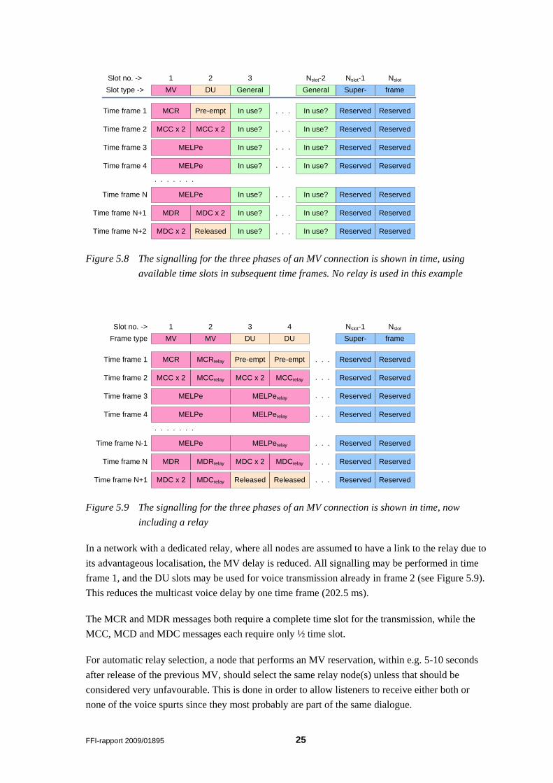
Figure 5.7 shows the time sequence diagram of the peer message exchange of a successful MV
session in which there is one relay node and one additional CC node. In general there may be up
to three additional CC nodes. Figure 5.8 shows the associated signalling messages in time slots
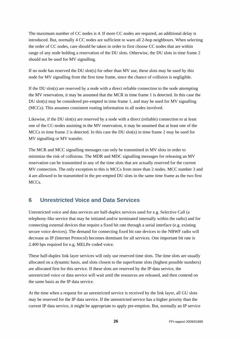
and time frames for a case without relays but with up to 4 CC nodes. Figure 5.9 shows the same
signalling in a case with one relay. In these two cases two time slots are required to transfer a
voice stream, e.g. using MELPe (2.4 kbps) at the lowest PHY mode (N1).
Figure 5.7 The time sequence diagram shows the 3 phases of a multicast voice session. The
example includes a relay which must perform its own reservation (not shown here).
There may be more than two CC nodes
MV Connect Request
Relay MCR w/ original MCC
PTT
Last MV packet
w/MDR
CC-node
MCR (relay)
MV Connect Confirm x N
MV Connect Request
Multicast voice
packets
PTT release
MV Disconnect Confirm
x n
MDR (relay) Relay MDR w/ original MDC
.
.
.
.
.
.
.
.
MV packets relayed
Relay node Initiator
FFI-rapport 2009/01895 25
frameSuper-GeneralGeneralDUMV
ReservedReservedIn use?In use?Pre-emptMCR
1 2 3 Nslot-2 Nslot-1 Nslot
Slot type ->
Time frame 1
Slot no. ->
In use?In use?MCC x 2MCC x 2Time frame 2
MELPeTime frame 3
MELPeTime frame 4
MELPeTime frame N
Time frame N+1 MDC x 2MDR
Time frame N+2 MDC x 2 Released
. . . . . . .
ReservedReserved
ReservedReserved
ReservedReserved
ReservedReserved
ReservedReserved
ReservedReserved
In use?
In use? In use?
In use?
In use?
In use?
In use?In use?
In use?
In use?
. . .
. . .
. . .
. . .
. . .
. . .
. . .
Figure 5.8 The signalling for the three phases of an MV connection is shown in time, using
available time slots in subsequent time frames. No relay is used in this example
frameSuper-DUMV
ReservedReservedPre-emptMCR
1 2 3 4 Nslot-1 Nslot
Frame type
Time frame 1
Slot no. ->
MCCrelayMCC x 2Time frame 2
MELPeTime frame 3
MELPeTime frame 4
MELPeTime frame N-1
Time frame N MDC x 2MDR
Time frame N+1 MDC x 2 Released
. . . . . . .
ReservedReserved
ReservedReserved
ReservedReserved
ReservedReserved
ReservedReserved
ReservedReserved
. . .
. . .
. . .
. . .
. . .
. . .
Pre-emptMCRrelay
DUMV
. . .
MCC x 2MCCrelay
MELPerelay
MELPerelay
MELPerelay
MDRrelay
Released
MDCrelay
MDCrelay
Figure 5.9 The signalling for the three phases of an MV connection is shown in time, now
including a relay
In a network with a dedicated relay, where all nodes are assumed to have a link to the relay due to
its advantageous localisation, the MV delay is reduced. All signalling may be performed in time
frame 1, and the DU slots may be used for voice transmission already in frame 2 (see Figure 5.9).
This reduces the multicast voice delay by one time frame (202.5 ms).
The MCR and MDR messages both require a complete time slot for the transmission, while the
MCC, MCD and MDC messages each require only ½ time slot.
For automatic relay selection, a node that performs an MV reservation, within e.g. 5-10 seconds
after release of the previous MV, should select the same relay node(s) unless that should be
considered very unfavourable. This is done in order to allow listeners to receive either both or
none of the voice spurts since they most probably are part of the same dialogue.
26 FFI-rapport 2009/01895
The maximum number of CC nodes is 4. If more CC nodes are required, an additional delay is
introduced. But, normally 4 CC nodes are sufficient to warn all 2-hop neighbours. When selecting
the order of CC nodes, care should be taken in order to first choose CC nodes that are within
range of any node holding a reservation of the DU slots. Otherwise, the DU slots in time frame 2
should not be used for MV signalling.
If no node has reserved the DU slot(s) for other than MV use, these slots may be used by this
node for MV signalling from the first time frame, since the chance of collision is negligible.
If the DU slot(s) are reserved by a node with a direct reliable connection to the node attempting
the MV reservation, it may be assumed that the MCR in time frame 1 is detected. In this case the
DU slot(s) may be considered pre-empted in time frame 1, and may be used for MV signalling
(MCCs). This assumes consistent routing information in all nodes involved.
Likewise, if the DU slot(s) are reserved by a node with a direct (reliable) connection to at least
one of the CC-nodes assisting in the MV reservation, it may be assumed that at least one of the
MCCs in time frame 2 is detected. In this case the DU slot(s) in time frame 2 may be used for
MV signalling or MV transfer.
The MCR and MCC signalling messages can only be transmitted in MV slots in order to
minimize the risk of collisions. The MDR and MDC signalling messages for releasing an MV
reservation can be transmitted in any of the time slots that are actually reserved for the current
MV connection. The only exception to this is MCCs from more than 2 nodes. MCC number 3 and
4 are allowed to be transmitted in the pre-empted DU slots in the same time frame as the two first
MCCs.
6 Unrestricted Voice and Data Services
Unrestricted voice and data services are half-duplex services used for e.g. Selective Call (a
telephony-like service that may be initiated and/or terminated internally within the radio) and for
connecting external devices that require a fixed bit rate through a serial interface (e.g. existing
secure voice devices). The demand for connecting fixed bit rate devices to the NBWF radio will
decrease as IP (Internet Protocol) becomes dominant for all services. One important bit rate is
2.400 bps required for e.g. MELPe coded voice.
These half-duplex link layer services will only use reserved time slots. The time slots are usually
allocated on a dynamic basis, and slots closest to the superframe slots (highest possible numbers)
are allocated first for this service. If these slots are reserved by the IP data service, the
unrestricted voice or data service will wait until the resources are released, and then contend on
the same basis as the IP data service.
At the time when a request for an unrestricted service is received by the link layer, all GU slots
may be reserved for the IP data service. If the unrestricted service has a higher priority than the
current IP data service, it might be appropriate to apply pre-emption. But, normally an IP service
FFI-rapport 2009/01895 27
will be valid for up to approximately 1500 bytes IP payload. Then the reservation will be released
within 1-2 seconds even at the lowest data date, unless a poor link quality results in several re-
transmissions. This low delay may be acceptable, thereby reducing the requirement for pre-
emption.
The reservation process for unrestricted services is very similar to that of IP data (see section 7.2).
The same General Reservation mechanism is used, but with one difference. Contrary to IP data,
only the required number of slots to support the requested transport data rate is reserved. DU slots
are not available for these services, so unreserved slots closest to the SF slots (highest slot
number) are selected for these services.
7 IP data Services
The IP data service provided by the link layer (LLC) to the network layer (3a) is connectionless.
LLC receives data PDUs from 3a for transmission on-air, and delivers on-air received data PDUs
to the network layer. The only other primitives exchanged between LLC and 3a are for hand-
shake related to buffer control in LLC. When LLC buffers are full, an XOFF message is sent to
3a, succeeded by an XON when buffer space is available again.
7.1 The different transport services available to IP data
IP data may access two different link layer services (LLC services), although LLC may utilise
three different transport mechanisms (MAC services). The two LLC services are:
LLC Fixed Access
LLC Contention Access
The LLC Fixed Access service is directly mapped on to a MAC Fixed Access service which
utilises the fixed allocated superframe time slots for transport. This service requires no
reservation and is never exposed to contention.
The LLC Contention Access service is mapped on to one of two different MAC transport
services:
MAC Connectionless transport
MAC Connection oriented transport
28 FFI-rapport 2009/01895
7.1.1 The fixed access transport service
Normally, each node in the network is allocated a minimum, fixed data capacity through the
superframe structure6. This enables each node regular chances to transmit without contention. The
fixed capacity may be utilised for the IP data service. But in cases with long packets, the delay
may become significant if the packet has to be split up into several transmissions. This is due to
the fact that a very limited number of time slots are available to each node, at intervals that are
typically several seconds (depends on the number of nodes sharing this capacity).
7.1.2 The connectionless transport service
Contention access is the simplest but least reliable link layer service. In this case a node will try to
access what it assumes to be a free channel (in dynamic time slots) in order to transmit a MAC
PDU. The access must be regulated by an access protocol in order to prevent too many collisions
when the traffic load is high (queuing in many nodes). Since there is large chance of collision,
this service should not be used for long IP packets. Typically, this service is used for short
packets with a requirement to low delay and where guarantee of delivery is not so important. This
may e.g. be used for the distribution of situation awareness updates.
7.1.3 The connection-oriented transport service
For large packets (resulting in the transmission of more than one segment, see section 7.6) and
when guarantee of delivery is more important than low delay, we recommend the use of the
contention-free access based on reservation. A slot reservation for the IP data service is
performed for the 1-hop transfer7 of one or a few LLC PDUs (IP packets) only or at least limited
to a maximum of e.g. 2 Kbytes, before the reserved slots must be released again. This limitation is
enforced in order to achieve a fair sharing of the common channel resource between the nodes.
The reservation process is very similar to that for multicast voice. A node trying to reserve time
slots for data could choose to use its fixed resource allocation for the reservation. But this should
be done with care as it can affect fairness (between nodes) and priority. Otherwise, it must send
its reservation request in an unreserved time period. But, since the probability of reservation
collision is by far greater for data compared to MV8, we need to distribute the reservation requests
sent in unreserved time slots over a certain time period.
6 The use of superframe allocation is an option, and the number of slots allocated (in each time frame) for
this is up to the users to decide. 7 Relaying of IP data is performed by the network layer. 8 Voice events are normally less frequent than data packets. In addition, voice access is controlled by
disciplined user conventions.
FFI-rapport 2009/01895 29
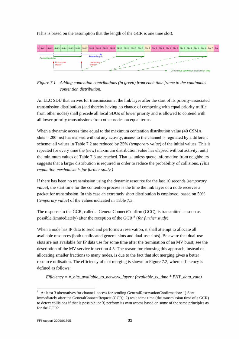
7.1.4 Comparison of MAC transport services
Table 7.1 summarises the recommended use of the three different MAC transport services for IP
data:
Service Packet size Acceptable delay Probability of success
Fixed access All Long Very high
Connectionless Small Short Medium/low
Connection-oriented Large Medium High
Table 7.1 Comparing different MAC transport services
The IP data service based on the use of fixed allocated resources requires no medium access
mechanism and is not described any further in this document. The access mechanism for the IP
data service based on contention access is described in chapter 7.11.
7.2 IP Data Reservation contention
If all nodes were able to inform their neighbours about their queue status, each node could form
an impression of the network load at each priority level. Optionally, it could also detect which
neighbour has the oldest packet at the highest priority. This is the packet that ideally should be
transmitted first. In this way it is possible, at least in theory, to build a network queue of nodes for
the access of the dynamic capacity. In practice it is difficult to obtain the same view in all the
network nodes. Even with information exchange such a system will not work perfectly, but we
should aim at achieving access according to a common network queue where the most important
and oldest packet is served first. At the same time we must restrict the information exchange
between the network nodes as this is expensive with regard to total network capacity.
For the transmission of reservation requests, called GeneralConnectRequest (GCR), we intend to
employ an access mechanism similar to slotted p-persistent CSMA, but with a uniform
distribution between a first and last possible transmit time. MV time slots are not used for such
access, neither are superframe slots9. We employ a CSMA contention slot size (in the access
protocol) that approximately equals the maximum time from a node decides to transmit until
another node is able to detect the ongoing transmission (Net sync + Rx/Tx switching +
propagation + preamble ≈ 4 ms). At the start of the contention period, each node draws a random
start time (to transmit) from the uniform distribution10. In order to obtain the best achievable
service (low delays and high throughput) under all conditions, this distribution is dynamic. Also,
to differentiate between priority levels (currently, two levels are proposed), we use different
distributions for the different priorities. They are to some extent overlapping for different
9 With the exception that a node may (of course) use its own allocated SF slots without contention as
mentioned initially in this chapter. 10 The transmission will always start at the beginning of the selected CSMA contention slot.
30 FFI-rapport 2009/01895
priorities in order to reduce the delay for low priority packets in case there are no high priority
packets.
The regulation mechanism in a node will be based on known information about:
Number of neighbour nodes
Perceived traffic load
Network queuing at different priorities (if available)
A node waiting for its selected transmission time and detecting someone else starting a
transmission, will refrain from transmitting and attempt a new access once the channel is free
again. The transmission start time is selected from a distribution which is regulated within some
maximum and minimum values, of which an example is given in Table 7.2 and Table 7.3
respectively.
When no information about packet queuing in neighbour nodes is available (due to initial network
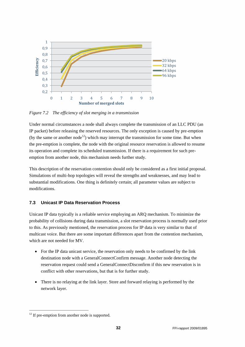
establishment) the maximum values in Table 7.2 are used.
Priority level First start time Last start time
High 0 16 CSMA slots
Low 14 CSMA slots 34 CSMA slots
Table 7.2 Example maximum values for the distribution of data reservation accesses. All
values are related to a CSMA contention slot size of ≈ 4 ms. All values are
temporary and exposed to later modifications.(These values are only indicative.)
Priority level First start time Last start time
High 0 12 CSMA slots
Low 10 CSMA slots 24 CSMA slots
Table 7.3 Example minimum values for the distribution of data reservation accesses. All values
are related to a CSMA contention slot size of ≈ 4 ms. All values are temporary and
exposed to later modifications. (These values are only indicative.)
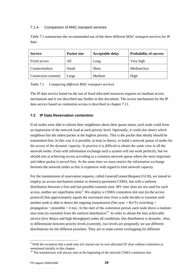
Since a selected transmission time may be later than the available time between the last MV time
slot and the first SF time slot, we need to extend the running time for the transmission distribution
into the next time frame. The distribution starts from the first time slot after the release of the last
reservation. For every time frame the available free contention time (total time for all free time
slots minus time required to transmit a reservation) is added to the continuous contention
distribution time as shown in Figure 7.1. The start of the last free slot is the latest possible starting
point for the transmission of a reservation in the current time frame.
FFI-rapport 2009/01895 31
(This is based on the assumption that the length of the GCR is one time slot).
Frame lengthContention time
Slot 1 Slot 2 Slot 4 Slot 7Slot 6Slot 5 Slot 9Slot 9
Continuous contention distribution time
First access
chance
Last access
chance
Slot 3 Slot 8 Slot 1 Slot 2 Slot 4 Slot 7Slot 6Slot 5 Slot 9Slot 3 Slot 8 Slot 1 Slot 2 Slot 4 Slot 7Slot 6Slot 5Slot 3 Slot 8
Figure 7.1 Adding contention contributions (in green) from each time frame to the continuous
contention distribution.
An LLC SDU that arrives for transmission at the link layer after the start of its priority-associated
transmission distribution (and thereby having no chance of competing with equal priority traffic
from other nodes) shall precede all local SDUs of lower priority and is allowed to contend with
all lower priority transmissions from other nodes on equal terms.
When a dynamic access time equal to the maximum contention distribution value (40 CSMA
slots ≈ 200 ms) has elapsed without any activity, access to the channel is regulated by a different
scheme: all values in Table 7.2 are reduced by 25% (temporary value) of the initial values. This is
repeated for every time the (new) maximum distribution value has elapsed without activity, until
the minimum values of Table 7.3 are reached. That is, unless queue information from neighbours
suggests that a larger distribution is required in order to reduce the probability of collisions. (This
regulation mechanism is for further study.)
If there has been no transmission using the dynamic resource for the last 10 seconds (temporary
value), the start time for the contention process is the time the link layer of a node receives a
packet for transmission. In this case an extremely short distribution is employed, based on 50%
(temporary value) of the values indicated in Table 7.3.
The response to the GCR, called a GeneralConnectConfirm (GCC), is transmitted as soon as
possible (immediately) after the reception of the GCR11 (for further study).
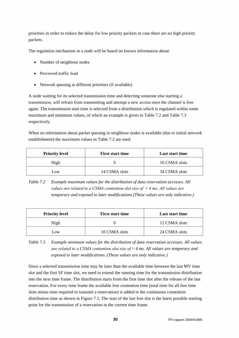
When a node has IP data to send and performs a reservation, it shall attempt to allocate all
available resources (both unallocated general slots and dual-use slots). Be aware that dual-use
slots are not available for IP data use for some time after the termination of an MV burst; see the
description of the MV service in section 4.5. The reason for choosing this approach, instead of
allocating smaller fractions to many nodes, is due to the fact that slot merging gives a better
resource utilisation. The efficiency of slot merging is shown in Figure 7.2, where efficiency is
defined as follows:
Efficiency = #_bits_available_to_network_layer / (available_tx_time * PHY_data_rate)
11 At least 3 alternatives for channel access for sending GeneralReservationConfirmation: 1) Sent
immediately after the GeneralConnectRequest (GCR); 2) wait some time (the transmission time of a GCR)
to detect collisions if that is possible; or 3) perform its own access based on some of the same principles as
for the GCR?
32 FFI-rapport 2009/01895
Figure 7.2 The efficiency of slot merging in a transmission
Under normal circumstances a node shall always complete the transmission of an LLC PDU (an
IP packet) before releasing the reserved resources. The only exception is caused by pre-emption
(by the same or another node12) which may interrupt the transmission for some time. But when
the pre-emption is complete, the node with the original resource reservation is allowed to resume
its operation and complete its scheduled transmission. If there is a requirement for such pre-
emption from another node, this mechanism needs further study.
This description of the reservation contention should only be considered as a first initial proposal.
Simulations of multi-hop topologies will reveal the strengths and weaknesses, and may lead to
substantial modifications. One thing is definitely certain; all parameter values are subject to
modifications.
7.3 Unicast IP Data Reservation Process
Unicast IP data typically is a reliable service employing an ARQ mechanism. To minimize the
probability of collisions during data transmission, a slot reservation process is normally used prior
to this. As previously mentioned, the reservation process for IP data is very similar to that of
multicast voice. But there are some important differences apart from the contention mechanism,
which are not needed for MV.
For the IP data unicast service, the reservation only needs to be confirmed by the link
destination node with a GeneralConnectConfirm message. Another node detecting the
reservation request could send a GeneralConnectDisconfirm if this new reservation is in
conflict with other reservations, but that is for further study.
There is no relaying at the link layer. Store and forward relaying is performed by the
network layer.
12 If pre-emption from another node is supported.
0,2
0,3
0,4
0,5
0,6
0,7
0,8
0,9
1
0 1 2 3 4 5 6 7 8 9 10
Eff
icie
ncy
Number of merged slots
20 kbps32 kbps64 kbps96 kbps
FFI-rapport 2009/01895 33
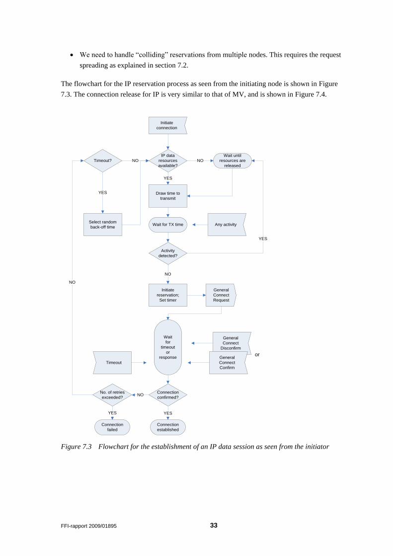
We need to handle “colliding” reservations from multiple nodes. This requires the request
spreading as explained in section 7.2.
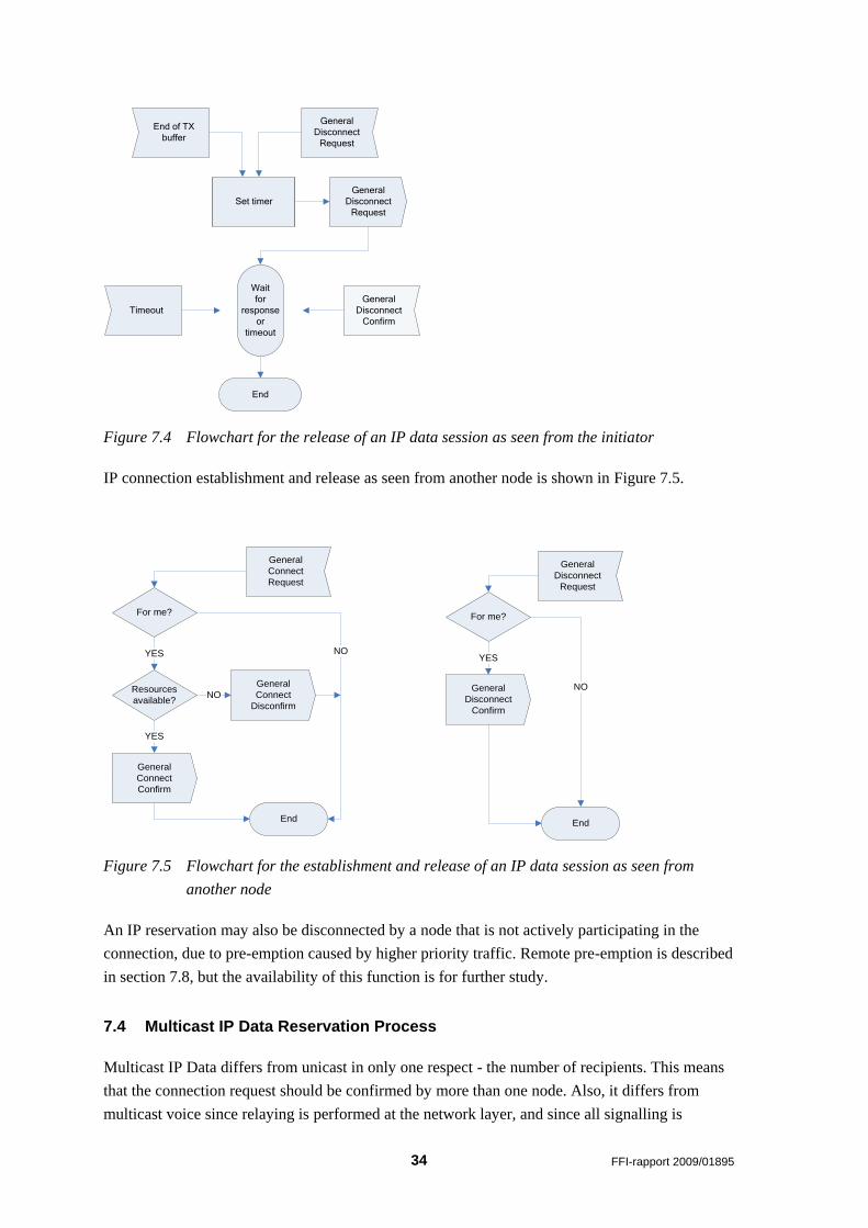
The flowchart for the IP reservation process as seen from the initiating node is shown in Figure
7.3. The connection release for IP is very similar to that of MV, and is shown in Figure 7.4.
IP data
resources
available?
NO
YES
Draw time to
transmit
Initiate
reservation;
Set timer
YES
Connection
established
Initiate
connection
Wait
for
timeout
or
response
General
Connect
Request
Timeout
Wait until
resources are
released
Wait for TX time Any activity
Activity
detected?
YES
NO
General
Connect
Disconfirm
Connection
confirmed?
orGeneral
Connect
Confirm
Timeout? NO
YES
Select random
back-off time
No. of retries
exceeded?
YES
Connection
failed
NO
NO
Figure 7.3 Flowchart for the establishment of an IP data session as seen from the initiator
34 FFI-rapport 2009/01895
General
Disconnect
Request
General
Disconnect
Request
End
General
Disconnect
Confirm
Set timer
Timeout
End of TX
buffer
Wait
for
response
or
timeout
Figure 7.4 Flowchart for the release of an IP data session as seen from the initiator
IP connection establishment and release as seen from another node is shown in Figure 7.5.
Resources
available?NO
YES
End
For me?
YES NO
NO
General
Connect
Request
General
Connect
Disconfirm
General
Connect
Confirm
End
For me?
YES
NO
General
Disconnect
Request
General
Disconnect
Confirm
Figure 7.5 Flowchart for the establishment and release of an IP data session as seen from
another node
An IP reservation may also be disconnected by a node that is not actively participating in the
connection, due to pre-emption caused by higher priority traffic. Remote pre-emption is described
in section 7.8, but the availability of this function is for further study.
7.4 Multicast IP Data Reservation Process
Multicast IP Data differs from unicast in only one respect - the number of recipients. This means
that the connection request should be confirmed by more than one node. Also, it differs from
multicast voice since relaying is performed at the network layer, and since all signalling is
FFI-rapport 2009/01895 35
performed in DU and GU slots where contention is greater. A reliable multicast service will
require an ARQ mechanism with acknowledgements from all recipients. This service level is very
expensive with regard to resources consumed. But, many applications using multicast (or
broadcast) have no explicit requirements to such a service level. The most important application
using multicast is situational awareness (SA). SA will transmit updated information typically at
regular intervals. Using a reliable service over a narrowband channel will often result in the
infrequent and delayed delivery of outdated information. A multicast service without ARQ
consumes a minimum of resources and rapidly delivers the data to receivers within the radio
range of the transmitter. An extended service could be obtained by allowing one or more (a very
limited number) nodes to relay the information. This extends the range of delivery while still
keeping the resource consumption at a reasonably low level.
An unreliable multicast service is easy to implement and should be specified for NBWF. Whether
or not to specify a reliable multicast service is for further study. The following points should be
clarified before specifying a reliable multicast service:
What kind of guarantee of delivery is required?
How many nodes should confirm the reservation?
How many nodes, if any, should acknowledge the data?
Should data be relayed by one or more nodes if extended coverage beyond radio range is
required?
Should data be transmitted more than once to improve delivery when not acknowledged?
7.5 Radio silence (EMCON)
EMCON (Emissions Control) may be applied to a network or only specific radio nodes. When
applied to the network, no services may be offered. But when individual nodes are under
EMCOM, it may still be possible for other radios to transmit data to these (silent) radios. This
requires that the EMCON status of the intended receiver is known. Of course, no service
requiring ARQ may be used, as the recipient is not allowed to acknowledge. Unreliable multicast
may be received by the silent nodes. Also, it is possible to design a dedicated unicast service that
requires no ARQ. Since acknowledgement and retransmission is impossible, successful delivery
is unreliable but might be improved by performing redundant transmission of the data. The
number of transmissions is a trade-off between probability of delivery and cost (use of radio
resources), and might be a dynamic figure depending on knowledge of link/path properties
obtained prior to EMCON. The final specification of IP data services related to EMCON is for
further study.
36 FFI-rapport 2009/01895
7.6 Segmentation
The most used maximum transmission unit (MTU) on Ethernet is 1500 bytes. This is the
maximum size of an IP packet including the IP header. Initially, let us assume the same maximum
transmission unit for NBWF, as much traffic will arrive to the radio over an Ethernet interface.
The maximum size of an SDU received by the Link layer from Network layer then is 1500 bytes.
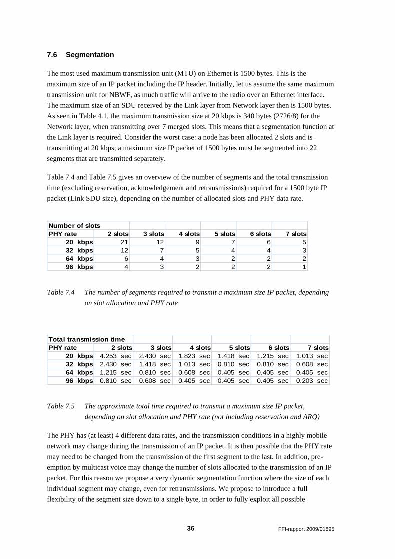
As seen in Table 4.1, the maximum transmission size at 20 kbps is 340 bytes (2726/8) for the
Network layer, when transmitting over 7 merged slots. This means that a segmentation function at
the Link layer is required. Consider the worst case: a node has been allocated 2 slots and is
transmitting at 20 kbps; a maximum size IP packet of 1500 bytes must be segmented into 22
segments that are transmitted separately.
Table 7.4 and Table 7.5 gives an overview of the number of segments and the total transmission
time (excluding reservation, acknowledgement and retransmissions) required for a 1500 byte IP
packet (Link SDU size), depending on the number of allocated slots and PHY data rate.
Table 7.4 The number of segments required to transmit a maximum size IP packet, depending
on slot allocation and PHY rate
Table 7.5 The approximate total time required to transmit a maximum size IP packet,
depending on slot allocation and PHY rate (not including reservation and ARQ)
The PHY has (at least) 4 different data rates, and the transmission conditions in a highly mobile
network may change during the transmission of an IP packet. It is then possible that the PHY rate
may need to be changed from the transmission of the first segment to the last. In addition, pre-
emption by multicast voice may change the number of slots allocated to the transmission of an IP
packet. For this reason we propose a very dynamic segmentation function where the size of each
individual segment may change, even for retransmissions. We propose to introduce a full
flexibility of the segment size down to a single byte, in order to fully exploit all possible
PHY rate 2 slots 3 slots 4 slots 5 slots 6 slots 7 slots
20 kbps 21 12 9 7 6 5
32 kbps 12 7 5 4 4 3
64 kbps 6 4 3 2 2 2
96 kbps 4 3 2 2 2 1
Number of slots
PHY rate 2 slots 3 slots 4 slots 5 slots 6 slots 7 slots
20 kbps 4.253 sec 2.430 sec 1.823 sec 1.418 sec 1.215 sec 1.013 sec
32 kbps 2.430 sec 1.418 sec 1.013 sec 0.810 sec 0.810 sec 0.608 sec
64 kbps 1.215 sec 0.810 sec 0.608 sec 0.405 sec 0.405 sec 0.405 sec
96 kbps 0.810 sec 0.608 sec 0.405 sec 0.405 sec 0.405 sec 0.203 sec
Total transmission time
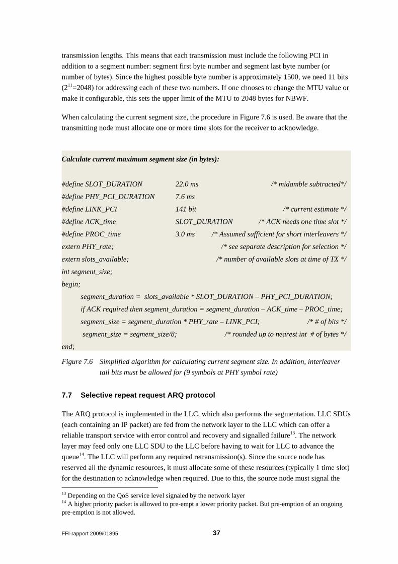
FFI-rapport 2009/01895 37
transmission lengths. This means that each transmission must include the following PCI in
addition to a segment number: segment first byte number and segment last byte number (or
number of bytes). Since the highest possible byte number is approximately 1500, we need 11 bits
(211=2048) for addressing each of these two numbers. If one chooses to change the MTU value or
make it configurable, this sets the upper limit of the MTU to 2048 bytes for NBWF.
When calculating the current segment size, the procedure in Figure 7.6 is used. Be aware that the
transmitting node must allocate one or more time slots for the receiver to acknowledge.
Figure 7.6 Simplified algorithm for calculating current segment size. In addition, interleaver
tail bits must be allowed for (9 symbols at PHY symbol rate)
7.7 Selective repeat request ARQ protocol
The ARQ protocol is implemented in the LLC, which also performs the segmentation. LLC SDUs
(each containing an IP packet) are fed from the network layer to the LLC which can offer a
reliable transport service with error control and recovery and signalled failure13. The network
layer may feed only one LLC SDU to the LLC before having to wait for LLC to advance the
queue14. The LLC will perform any required retransmission(s). Since the source node has
reserved all the dynamic resources, it must allocate some of these resources (typically 1 time slot)
for the destination to acknowledge when required. Due to this, the source node must signal the
13 Depending on the QoS service level signaled by the network layer 14 A higher priority packet is allowed to pre-empt a lower priority packet. But pre-emption of an ongoing
pre-emption is not allowed.
Calculate current maximum segment size (in bytes):
#define SLOT_DURATION 22.0 ms /* midamble subtracted*/
#define PHY_PCI_DURATION 7.6 ms
#define LINK_PCI 141 bit /* current estimate */
#define ACK_time SLOT_DURATION /* ACK needs one time slot */
#define PROC_time 3.0 ms /* Assumed sufficient for short interleavers */
extern PHY_rate; /* see separate description for selection */
extern slots_available; /* number of available slots at time of TX */
int segment_size;
begin;
segment_duration = slots_available * SLOT_DURATION – PHY_PCI_DURATION;
if ACK required then segment_duration = segment_duration – ACK_time – PROC_time;
segment_size = segment_duration * PHY_rate – LINK_PCI; /* # of bits */
segment_size = segment_size/8; /* rounded up to nearest int # of bytes */
end;
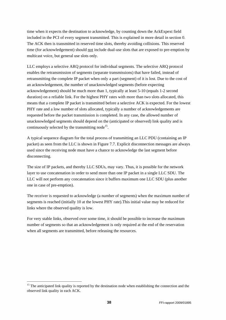
38 FFI-rapport 2009/01895
time when it expects the destination to acknowledge, by counting down the AckExpext field
included in the PCI of every segment transmitted. This is explained in more detail in section 0.
The ACK then is transmitted in reserved time slots, thereby avoiding collisions. This reserved
time (for acknowledgement) should not include dual-use slots that are exposed to pre-emption by
multicast voice, but general use slots only.
LLC employs a selective ARQ protocol for individual segments. The selective ARQ protocol
enables the retransmission of segments (separate transmissions) that have failed, instead of
retransmitting the complete IP packet when only a part (segment) of it is lost. Due to the cost of
an acknowledgement, the number of unacknowledged segments (before expecting
acknowledgement) should be much more than 1, typically at least 5-10 (equals 1-2 second
duration) on a reliable link. For the highest PHY rates with more than two slots allocated, this
means that a complete IP packet is transmitted before a selective ACK is expected. For the lowest
PHY rate and a low number of slots allocated, typically a number of acknowledgements are
requested before the packet transmission is completed. In any case, the allowed number of
unacknowledged segments should depend on the (anticipated or observed) link quality and is
continuously selected by the transmitting node15.
A typical sequence diagram for the total process of transmitting an LLC PDU (containing an IP
packet) as seen from the LLC is shown in Figure 7.7. Explicit disconnection messages are always
used since the receiving node must have a chance to acknowledge the last segment before
disconnecting.
The size of IP packets, and thereby LLC SDUs, may vary. Thus, it is possible for the network
layer to use concatenation in order to send more than one IP packet in a single LLC SDU. The
LLC will not perform any concatenation since it buffers maximum one LLC SDU (plus another
one in case of pre-emption).
The receiver is requested to acknowledge (a number of segments) when the maximum number of
segments is reached (initially 10 at the lowest PHY rate).This initial value may be reduced for
links where the observed quality is low.
For very stable links, observed over some time, it should be possible to increase the maximum
number of segments so that an acknowledgement is only required at the end of the reservation
when all segments are transmitted, before releasing the resources.
15 The anticipated link quality is reported by the destination node when establishing the connection and the
observed link quality in each ACK.
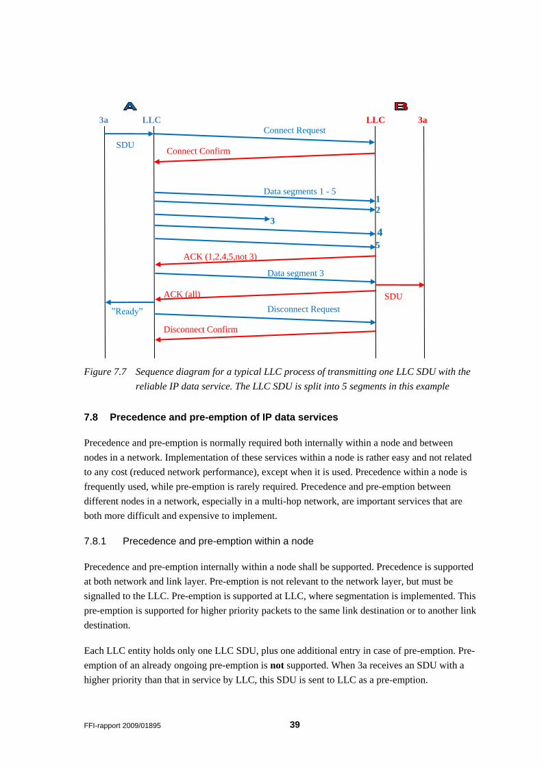
FFI-rapport 2009/01895 39
Figure 7.7 Sequence diagram for a typical LLC process of transmitting one LLC SDU with the
reliable IP data service. The LLC SDU is split into 5 segments in this example
7.8 Precedence and pre-emption of IP data services
Precedence and pre-emption is normally required both internally within a node and between
nodes in a network. Implementation of these services within a node is rather easy and not related
to any cost (reduced network performance), except when it is used. Precedence within a node is
frequently used, while pre-emption is rarely required. Precedence and pre-emption between
different nodes in a network, especially in a multi-hop network, are important services that are
both more difficult and expensive to implement.
7.8.1 Precedence and pre-emption within a node
Precedence and pre-emption internally within a node shall be supported. Precedence is supported
at both network and link layer. Pre-emption is not relevant to the network layer, but must be
signalled to the LLC. Pre-emption is supported at LLC, where segmentation is implemented. This
pre-emption is supported for higher priority packets to the same link destination or to another link
destination.
Each LLC entity holds only one LLC SDU, plus one additional entry in case of pre-emption. Pre-
emption of an already ongoing pre-emption is not supported. When 3a receives an SDU with a
higher priority than that in service by LLC, this SDU is sent to LLC as a pre-emption.
3a
Connect Request
Connect Confirm
Data segments 1 - 5
ACK (1,2,4,5,not 3)
ACK (all)
1
2
4
Data segment 3
Disconnect Request
Disconnect Confirm
3
LLC 3a LLC
SDU
”Ready”
SDU
5

40 FFI-rapport 2009/01895
When LLC receives a pre-emption candidate it makes a decision based on the estimated
remaining time for the ongoing lower priority SDU. When deciding on whether to pre-empt or
wait until current transmission is finished, the following rule is applied:
Traffic of priority class High will pre-empt traffic of priority class Low if the estimated
remaining session time exceeds 0.5 seconds.
All details are preliminary and subject to later modifications.
When pre-emption is effectuated, the current PDU is aborted, an ABORT message is sent to the
link destination and a new GCR is sent to the new link destination to initiate the transfer of the
pre-empting SDU.
An option to allow the pre-empted connection to resume when pre-emption is finished is for
further study.
The pre-emption process is shown in Figure 7.8 for both possible cases; pre-empting SDU is
destined to the same link destination or another link destination.
FFI-rapport 2009/01895 41
Figure 7.8 Flow chart for node internal pre-emption process at the LLC
42 FFI-rapport 2009/01895
7.8.2 Precedence and pre-emption in the network
Precedence in the network, between different nodes, is supported. But this support is not absolute.
E.g., when two nodes with different priority packets contend for transmission, there can be
situations where the node with the lower priority packet wins the reservation contention and is
transmitted first. But, in general, higher priority packets are served before lower priority packets.
Support of pre-emption between nodes in the network will be considered in the future, depending
on the requirement for such a service. This might be an expensive service that requires the
reservation of some network capacity in order to be able to interrupt a node with a low priority
packet. The cost, in reduced network throughput, depends on the delay requirement related to pre-
emption. There is also an additional complexity regarding situations when a node that wants to
pre-empt is not a neighbour of the node that has reserved the channel. In such cases an
intermediary node must be found and informed. This also increases the delay.
Whether to reserve dedicated resources for very rapid pre-emption or whether to let a pre-empting
node wait for its own fixed time slots for pre-emption should be subject to a thorough assessment.
7.9 Relaying and prioritized access
If rapid end-to-end transfer of IP packets is desired, it is possible to allow a relay to have
preference to the reserved slots when released by the source node, but only to be used for the
forwarding of the packet to be relayed. This still means that the relay node will perform a
reservation (as soon as the reserved slots are freed), but with little or no contention from other
nodes. This might reduce the delay of packets traversing many hops. In a network of dimension
more than three hops, care must be taken in case of spatial slot-reuse as there might be a conflict
on the new link. This functionality is for further study.
7.10 Selection of PHY mode (data rate)
The selection of PHY rate for a given link is not a function that needs standardisation. The node
transmitting data chooses the mode to be used based on available information. What needs
standardisation is any information exchanged between radios that are used as input to the rate
selection algorithm. The receiving node will always select the most robust mode for its
acknowledgements, as any other signalling messages.
Generally, the link layer of the originating node selects the highest possible PHY mode that still
gives a robust two-way link. Robustness is initially defined as a receiver SNR margin of at least
20 dB (preliminary value), based on the measurement of the received CC and link quality
information in the CC (based on the destination‟s measurement of the CR). If historical link
quality data is available, as normally is, a smaller margin to the lowest observed SNR value
within the last period of e.g. 60 s should be selected. For a link with low variation this margin
may be less than 5 dB. The margin of a highly variable link should be set higher.
FFI-rapport 2009/01895 43
The PHY mode is normally not changed during the transmission of an LLC SDU. But, it can be
reduced, based of feed-back from the receiver in the selective acknowledgement(s). The
receiver‟s ACK reports the link quality, based on receiver signal strength measurements and bit
errors in segments (or failed segments). In order to increase the data rate, the link quality must
satisfy the margin of at least one mode higher than the new mode to be used. E.g. if a
transmission starts at mode N1 and the receiver finds out that the criteria to use mode N3 are
satisfied, mode N2 may be selected for the rest of the transmission and reported to the transmitter
in the ACK. Even though the receiver indicates that a different mode is recommended, the
decision on which mode that is actually used for the transmission is done by the transmitting
node.
As SNR is not the only parameter to describe link quality (e.g. in multipath environment), the
decision on which PHY mode to use should also be based on BER measurements or other
statistical information collected.
7.11 IP Data Service without Reservation
There are two ways a radio node can transmit without prior reservation:
- Use of the node‟s own fixed slots in the superframe structure can be used whenever
possible without contention.
- Use of DU and GU slots that are not reserved may be accessed for data transmission as
well as for reservations. Data transmissions in these slots are subject to contention, not
only by other data transmissions but also by reservations.
7.11.1 IP data transmission without contention (in fixed slots)
Data transmissions in fixed slots do not support segmentation (due to the long delay between such
transmissions). Also, this service should not be used for reliable delivery requiring
acknowledgement from the receiver, as the delay before ACK is received may become very long.
Typically, this service is used for network internal multicast/broadcast control traffic such as
routing updates, but is also ideal for user data such as regular situational awareness updates.
7.11.2 IP data transmission with contention
The contention-based service is provided for short messages only (limited to one single
transmission) since the probability of collision can be rather large. This means that segmentation
is not supported. Also, this service should not be used for reliable delivery. An SDU is
transmitted only once, and no notification of delivery (acknowledgement from the recipient) may
be expected. This service should be used when low latency has priority over guarantee of
delivery. Details of this service are for further study.
44 FFI-rapport 2009/01895
8 Network Configuration Options
The detailed description in this document is considered to be a typical example for a land
operation with a mixture of voice and data traffic. We propose that many network parameters
shall be configurable. The actual configuration of a network should be adapted to the actual
operation and the anticipated needs. The configuration is normally pre-loaded into the radio
together with other network parameters such as frequency and crypto keys.
Here is a list of relevant parameters to be configurable:
TDMA frame size in number of slots. 9 slots is a compromise between voice delay and data
protocol efficiency and should be selected for a combined voice and data network. In a voice
prioritised network the number of slots and/or the slot size could be changed, giving a TDMA
frame size of e.g. 135 ms.
Number of MV slots must be adapted to both the vocoder being used as well as the number of
multicast voice channels offered and the number of relays. In a voice prioritised network with
delay sensitive voice applications, it is also possible to use a fixed allocation of resources for MV,
and omit the dynamic slot reservation. This will reduce the initial delay otherwise introduced by
the reservation signalling. The penalty of fixed MV slot allocation is reduced dynamic capacity
for data.
Number of SF slots should be adapted to the data traffic pattern. In an operation where each
radio is anticipated to generate most of its data traffic regularly, it might be rational to allocate
more than two slots.
The length of the Superframe in number of TDMA frames should be adapted to the anticipated
number of radios in the network and their delay requirement related to this service. The SF slots
can be allocated evenly between all radios in the network, or some radios, which are expected to
“generate” more traffic, can be given more slots in the superframe.
The slot length is not proposed to be configurable for NBWF(L), but could be different for other
versions like NBWF(A). The use of other slots sizes is for further study, as that requires some
modifications both to the physical layer and the link layer.
9 Protocol Control Information
The length and composition of the MAC/LLC PCI (header) is variable, depending on the type of
service the PDU (frame) is related to and when it is transmitted. Control frames are always
transmitted using the lowest available physical data rate, which is usually mode N1 (20 kbps).
This chapter gives a first draft of the PCI. The details of the PCI are not very thought-through, as
the main purpose of writing it has been to get a reasonably reliable estimate of the header size of
the different frame types. The final specification of the PCI for NBWF will be described in the
relevant STANAG to come.
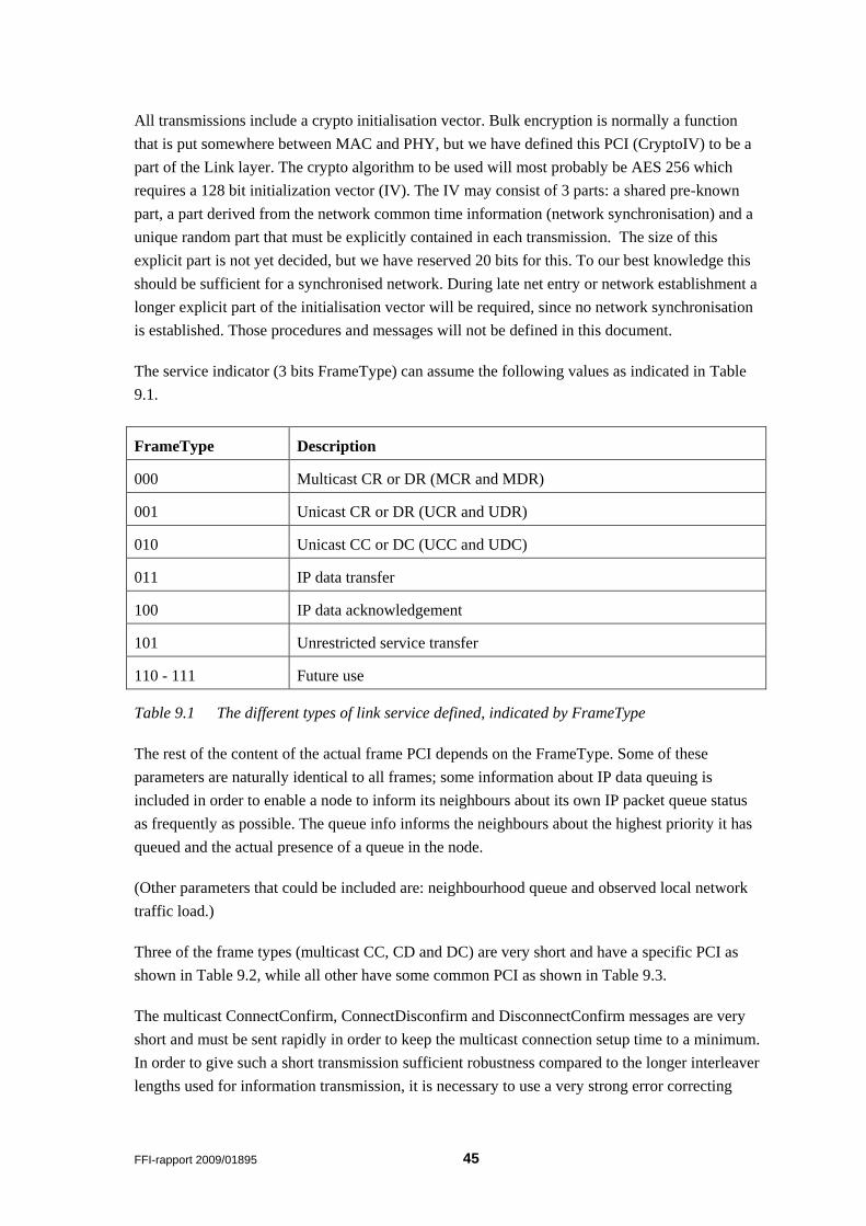
FFI-rapport 2009/01895 45
All transmissions include a crypto initialisation vector. Bulk encryption is normally a function
that is put somewhere between MAC and PHY, but we have defined this PCI (CryptoIV) to be a
part of the Link layer. The crypto algorithm to be used will most probably be AES 256 which
requires a 128 bit initialization vector (IV). The IV may consist of 3 parts: a shared pre-known
part, a part derived from the network common time information (network synchronisation) and a
unique random part that must be explicitly contained in each transmission. The size of this
explicit part is not yet decided, but we have reserved 20 bits for this. To our best knowledge this
should be sufficient for a synchronised network. During late net entry or network establishment a
longer explicit part of the initialisation vector will be required, since no network synchronisation
is established. Those procedures and messages will not be defined in this document.
The service indicator (3 bits FrameType) can assume the following values as indicated in Table
9.1.
FrameType Description
000 Multicast CR or DR (MCR and MDR)
001 Unicast CR or DR (UCR and UDR)
010 Unicast CC or DC (UCC and UDC)
011 IP data transfer
100 IP data acknowledgement
101 Unrestricted service transfer
110 - 111 Future use
Table 9.1 The different types of link service defined, indicated by FrameType
The rest of the content of the actual frame PCI depends on the FrameType. Some of these
parameters are naturally identical to all frames; some information about IP data queuing is
included in order to enable a node to inform its neighbours about its own IP packet queue status
as frequently as possible. The queue info informs the neighbours about the highest priority it has
queued and the actual presence of a queue in the node.
(Other parameters that could be included are: neighbourhood queue and observed local network
traffic load.)
Three of the frame types (multicast CC, CD and DC) are very short and have a specific PCI as
shown in Table 9.2, while all other have some common PCI as shown in Table 9.3.
The multicast ConnectConfirm, ConnectDisconfirm and DisconnectConfirm messages are very
short and must be sent rapidly in order to keep the multicast connection setup time to a minimum.
In order to give such a short transmission sufficient robustness compared to the longer interleaver
lengths used for information transmission, it is necessary to use a very strong error correcting
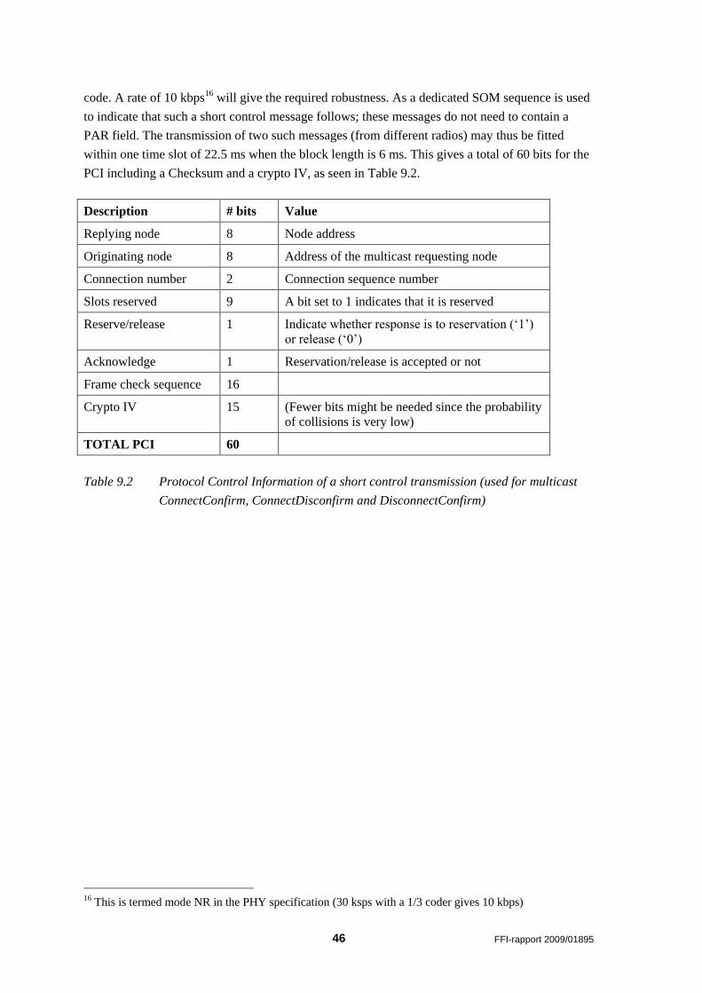
46 FFI-rapport 2009/01895
code. A rate of 10 kbps16 will give the required robustness. As a dedicated SOM sequence is used
to indicate that such a short control message follows; these messages do not need to contain a
PAR field. The transmission of two such messages (from different radios) may thus be fitted
within one time slot of 22.5 ms when the block length is 6 ms. This gives a total of 60 bits for the
PCI including a Checksum and a crypto IV, as seen in Table 9.2.
Description # bits Value
Replying node 8 Node address
Originating node 8 Address of the multicast requesting node
Connection number 2 Connection sequence number
Slots reserved 9 A bit set to 1 indicates that it is reserved
Reserve/release 1 Indicate whether response is to reservation („1‟)
or release („0‟)
Acknowledge 1 Reservation/release is accepted or not
Frame check sequence 16
Crypto IV 15 (Fewer bits might be needed since the probability
of collisions is very low)
TOTAL PCI 60
Table 9.2 Protocol Control Information of a short control transmission (used for multicast
ConnectConfirm, ConnectDisconfirm and DisconnectConfirm)
16 This is termed mode NR in the PHY specification (30 ksps with a 1/3 coder gives 10 kbps)
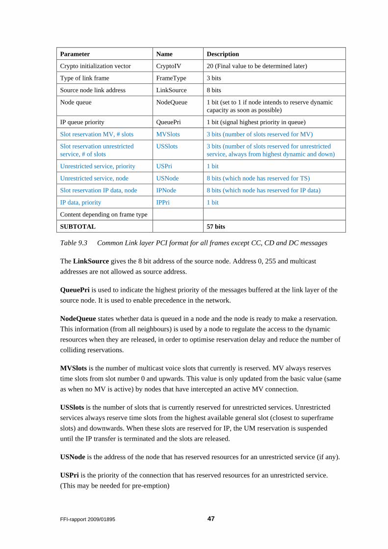
FFI-rapport 2009/01895 47
Parameter Name Description
Crypto initialization vector CryptoIV 20 (Final value to be determined later)
Type of link frame FrameType 3 bits
Source node link address LinkSource 8 bits
Node queue NodeQueue 1 bit (set to 1 if node intends to reserve dynamic
capacity as soon as possible)
IP queue priority QueuePri 1 bit (signal highest priority in queue)
Slot reservation MV, # slots MVSlots 3 bits (number of slots reserved for MV)
Slot reservation unrestricted
service, # of slots
USSlots 3 bits (number of slots reserved for unrestricted
service, always from highest dynamic and down)
Unrestricted service, priority USPri 1 bit
Unrestricted service, node USNode 8 bits (which node has reserved for TS)
Slot reservation IP data, node IPNode 8 bits (which node has reserved for IP data)
IP data, priority IPPri 1 bit
Content depending on frame type
SUBTOTAL 57 bits
Table 9.3 Common Link layer PCI format for all frames except CC, CD and DC messages
The LinkSource gives the 8 bit address of the source node. Address 0, 255 and multicast
addresses are not allowed as source address.
QueuePri is used to indicate the highest priority of the messages buffered at the link layer of the
source node. It is used to enable precedence in the network.
NodeQueue states whether data is queued in a node and the node is ready to make a reservation.
This information (from all neighbours) is used by a node to regulate the access to the dynamic
resources when they are released, in order to optimise reservation delay and reduce the number of
colliding reservations.
MVSlots is the number of multicast voice slots that currently is reserved. MV always reserves
time slots from slot number 0 and upwards. This value is only updated from the basic value (same
as when no MV is active) by nodes that have intercepted an active MV connection.
USSlots is the number of slots that is currently reserved for unrestricted services. Unrestricted
services always reserve time slots from the highest available general slot (closest to superframe
slots) and downwards. When these slots are reserved for IP, the UM reservation is suspended
until the IP transfer is terminated and the slots are released.
USNode is the address of the node that has reserved resources for an unrestricted service (if any).
USPri is the priority of the connection that has reserved resources for an unrestricted service.
(This may be needed for pre-emption)
48 FFI-rapport 2009/01895
IPNode is the address of the node that currently has reserved resources for the IP data service.
IPPri is the priority of the data that is currently transferred by the node holding the IP data
reservation. (This may be needed for pre-emption)
MVSlots, USSlots, USNode, USPri, IPNode and IPPri are all parameters that are used to
inform the network about current reservation status. The use of these parameters will be
considered, based on the experienced benefits observed in simulations.
In addition, there is a Frame Check Sequence included in all transmissions to detect bit errors.
Short control frames, unrestricted service frames and multicast voice frames are only protected by
a 16-bit CRC (possibly only protecting the PCI), while a 32-bit CRC is required in order to give a
sufficiently low error rate for data services (protecting both PCI and payload).
9.1 Control frames related to multicast voice
The Link PCI format of the two shortest control frames (MV Connect Confirm and MV
Disconnect Confirm) to be used for acknowledgement of slot reservation/release for multicast
voice are shown in Table 9.2. As previously mentioned, these short control frames need no
indication relating them to MV, since they may only be transmitted in slots related to MV. They
also do not need a frame type identifier since this is the only type of frame with duration of less
than a time slot, and is therefore identified through PHY PCI.
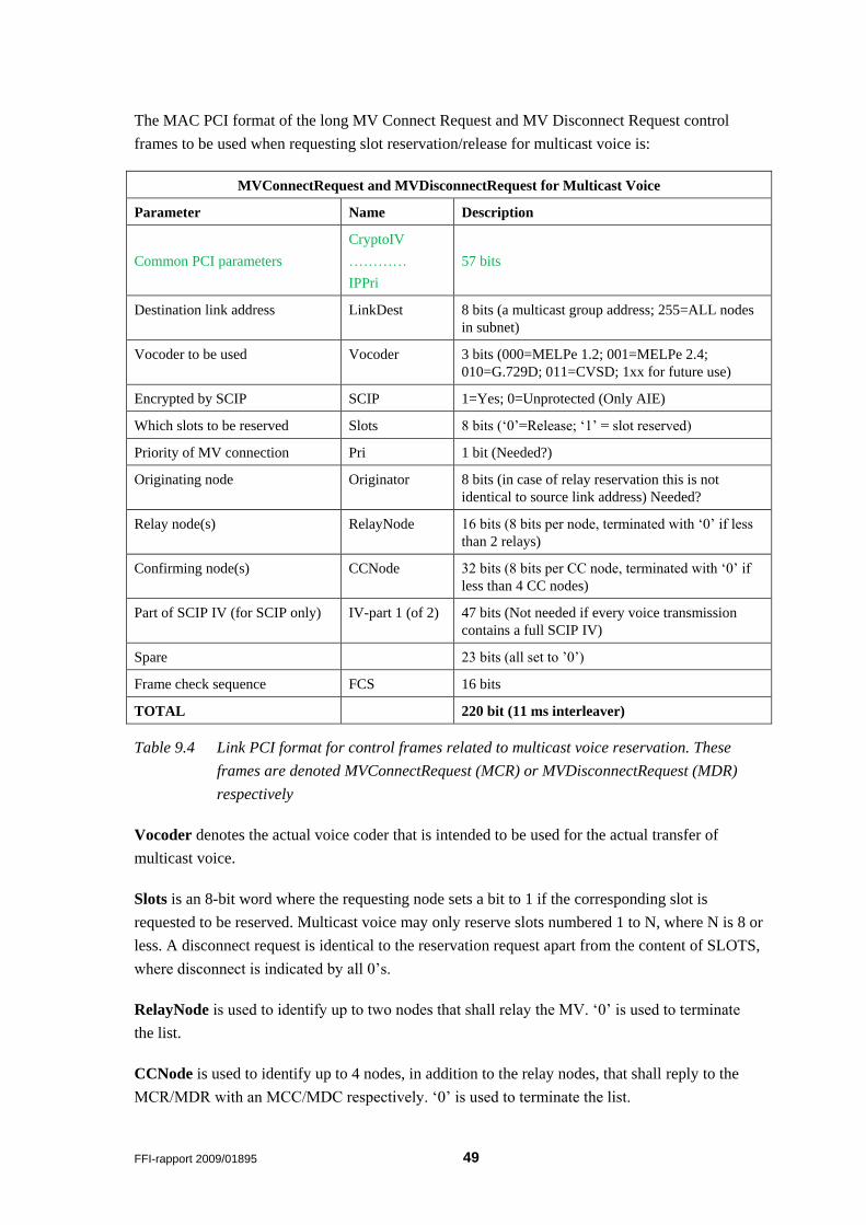
FFI-rapport 2009/01895 49
The MAC PCI format of the long MV Connect Request and MV Disconnect Request control
frames to be used when requesting slot reservation/release for multicast voice is:
MVConnectRequest and MVDisconnectRequest for Multicast Voice
Parameter Name Description
Common PCI parameters
CryptoIV
…………
IPPri
57 bits
Destination link address LinkDest 8 bits (a multicast group address; 255=ALL nodes
in subnet)
Vocoder to be used Vocoder 3 bits (000=MELPe 1.2; 001=MELPe 2.4;
010=G.729D; 011=CVSD; 1xx for future use)
Encrypted by SCIP SCIP 1=Yes; 0=Unprotected (Only AIE)
Which slots to be reserved Slots 8 bits („0‟=Release; „1‟ = slot reserved)
Priority of MV connection Pri 1 bit (Needed?)
Originating node Originator 8 bits (in case of relay reservation this is not
identical to source link address) Needed?
Relay node(s) RelayNode 16 bits (8 bits per node, terminated with „0‟ if less
than 2 relays)
Confirming node(s) CCNode 32 bits (8 bits per CC node, terminated with „0‟ if
less than 4 CC nodes)
Part of SCIP IV (for SCIP only) IV-part 1 (of 2) 47 bits (Not needed if every voice transmission
contains a full SCIP IV)
Spare 23 bits (all set to ‟0‟)
Frame check sequence FCS 16 bits
TOTAL 220 bit (11 ms interleaver)
Table 9.4 Link PCI format for control frames related to multicast voice reservation. These
frames are denoted MVConnectRequest (MCR) or MVDisconnectRequest (MDR)
respectively
Vocoder denotes the actual voice coder that is intended to be used for the actual transfer of
multicast voice.
Slots is an 8-bit word where the requesting node sets a bit to 1 if the corresponding slot is
requested to be reserved. Multicast voice may only reserve slots numbered 1 to N, where N is 8 or
less. A disconnect request is identical to the reservation request apart from the content of SLOTS,
where disconnect is indicated by all 0‟s.
RelayNode is used to identify up to two nodes that shall relay the MV. „0‟ is used to terminate
the list.
CCNode is used to identify up to 4 nodes, in addition to the relay nodes, that shall reply to the
MCR/MDR with an MCC/MDC respectively. „0‟ is used to terminate the list.
50 FFI-rapport 2009/01895
The CCDelay is used to signal the number of ½ MV slots before the first MCC is allowed to be
sent for this MCR. This is used in cases such as when a relay needs to send its MCR before the
MCCs for the previous MCR are sent.
9.2 Control frames related to general reservation
These control frames (Table 9.5) are used to reserve time slots for IP data services, unrestricted
services and selective call voice services. The services may be both unicast and multicast. For
multicast no guarantee of delivery to all intended recipients is given. The multicast service shall
only be considered to be best effort.
For unicast services, only the recipient shall reply to the reservation with a unicast CC (Table
9.6). Then the recipient shall include information about signal strength/link quality observed
when receiving the Connect Request. This is provided to the originator in order for him to select
the most appropriate PHY data rate. Both the CR and the CC shall be constructed as short as
possible in order to reduce the probability of collisions to a minimum.
For multicast services, the originator may request a CC from a selected number of confirming
nodes who will reply with a multicast CC or CD as specified in Table 9.2.
There may be situations where the reservation fails due to collisions or interference; either
because the CR is lost or because the CC is lost. In such instances all nodes that have detected
one of the messages shall refrain from reserving (or any other transmission) for a certain time
period. The originator(s) retransmits their reservation request (CR) once again, but with some
random spreading to handle the situations caused by colliding reservations. (For further study)
The node that wants to reserve resources for information transfer must select (optionally a
transmit power and) a PHY mode based on previous knowledge about the connection. If it is
uncertain about the quality of the connection, it shall select mode N1 (lowest data rate) (and
optionally the highest available transmit power).
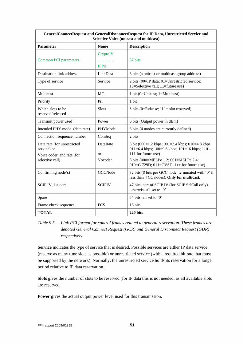
FFI-rapport 2009/01895 51
GeneralConnectRequest and GeneralDisconnectRequest for IP Data, Unrestricted Service and
Selective Voice (unicast and multicast)
Parameter Name Description
Common PCI parameters
CryptoIV
…………
IPPri
57 bits
Destination link address LinkDest 8 bits (a unicast or multicast group address)
Type of service Service 2 bits (00=IP data; 01=Unrestricted service;
10=Selective call; 11=future use)
Multicast MC 1 bit (0=Unicast; 1=Multicast)
Priority Pri 1 bit
Which slots to be
reserved/released
Slots 8 bits (0=Release; „1‟ = slot reserved)
Transmit power used Power 6 bits (Output power in dBm)
Intended PHY mode (data rate) PHYMode 3 bits (4 modes are currently defined)
Connection sequence number ConSeq 2 bits
Data rate (for unrestricted
service) or
Voice coder and rate (for
selective call)
DataRate
or
Vocoder
3 bit (000=1.2 kbps; 001=2.4 kbps; 010=4.8 kbps;
011=6.4 kbps; 100=9.6 kbps; 101=16 kbps; 110 –
111 for future use)
3 bits (000=MELPe 1.2; 001=MELPe 2.4;
010=G.729D; 011=CVSD; 1xx for future use)
Confirming node(s) GCCNode 32 bits (8 bits per GCC node, terminated with „0‟ if
less than 4 CC nodes). Only for multicast.
SCIP IV, 1st part SCIPIV 47 bits, part of SCIP IV (for SCIP SelCall only)
otherwise all set to „0‟
Spare 34 bits, all set to „0‟
Frame check sequence FCS 16 bits
TOTAL 220 bits
Table 9.5 Link PCI format for control frames related to general reservation. These frames are
denoted General Connect Request (GCR) and General Disconnect Request (GDR)
respectively
Service indicates the type of service that is desired. Possible services are either IP data service
(reserve as many time slots as possible) or unrestricted service (with a required bit rate that must
be supported by the network). Normally, the unrestricted service holds its reservation for a longer
period relative to IP data reservation.
Slots gives the number of slots to be reserved (for IP data this is not needed, as all available slots
are reserved.
Power gives the actual output power level used for this transmission.
52 FFI-rapport 2009/01895
PHYMode is used to indicate which mode (data rate) the originator intends to use for the
subsequent data transfer.
ConSeq is a sequence number used to identify which connection the frame is related to. Together
with source and destination node addresses this gives a unique connection identifier. A
connection lifetime ensures that no two connections using the same identifier exists
simultaneously.
For the unrestricted service two additional parameters are given:
DataRate is the user/application data rate that must be supported by the connection (for
unrestricted service only).
Vocoder specifies the type of voice coder and rate that is used (for selective call only).
GCCNode is used for multicast version of the services, and specifies up to 4 nodes to confirm the
reservation. (Not used for unicast services).
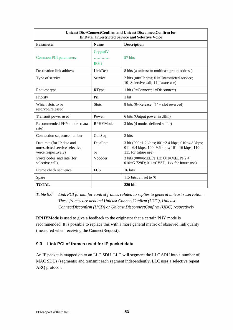
FFI-rapport 2009/01895 53
Unicast Dis-/ConnectConfirm and Unicast DisconnectConfirm for
IP Data, Unrestricted Service and Selective Voice
Parameter Name Description
Common PCI parameters
CryptoIV
…………
IPPri
57 bits
Destination link address LinkDest 8 bits (a unicast or multicast group address)
Type of service Service 2 bits (00=IP data; 01=Unrestricted service;
10=Selective call; 11=future use)
Request type RType 1 bit (0=Connect; 1=Disconnect)
Priority Pri 1 bit
Which slots to be
reserved/released
Slots 8 bits (0=Release; „1‟ = slot reserved)
Transmit power used Power 6 bits (Output power in dBm)
Recommended PHY mode (data
rate)
RPHYMode 3 bits (4 modes defined so far)
Connection sequence number ConSeq 2 bits
Data rate (for IP data and
unrestricted service selective
voice respectively)
Voice coder and rate (for
selective call)
DataRate
or
Vocoder
3 bit (000=1.2 kbps; 001=2.4 kbps; 010=4.8 kbps;
011=6.4 kbps; 100=9.6 kbps; 101=16 kbps; 110 –
111 for future use)
3 bits (000=MELPe 1.2; 001=MELPe 2.4;
010=G.729D; 011=CVSD; 1xx for future use)
Frame check sequence FCS 16 bits
Spare 115 bits, all set to „0‟
TOTAL 220 bit
Table 9.6 Link PCI format for control frames related to replies to general unicast reservation.
These frames are denoted Unicast ConnectConfirm (UCC), Unicast
ConnectDisconfirm (UCD) or Unicast DisconnectConfirm (UDC) respectively
RPHYMode is used to give a feedback to the originator that a certain PHY mode is
recommended. It is possible to replace this with a more general metric of observed link quality
(measured when receiving the ConnectRequest).
9.3 Link PCI of frames used for IP packet data
An IP packet is mapped on to an LLC SDU. LLC will segment the LLC SDU into a number of
MAC SDUs (segments) and transmit each segment independently. LLC uses a selective repeat
ARQ protocol.
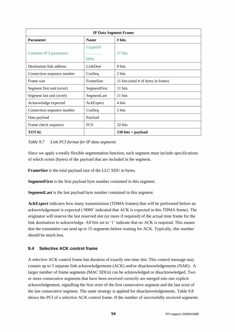
54 FFI-rapport 2009/01895
IP Data Segment Frame
Parameter Name # bits
Common PCI parameters
CryptoIV
…………
IPPri
57 bits
Destination link address LinkDest 8 bits
Connection sequence number ConSeq 2 bits
Frame size FrameSize 11 bits (total # of bytes in frame)
Segment first unit (octet) SegmentFirst 11 bits
Segment last unit (octet) SegmentLast 11 bits
Acknowledge expected AckExpect 4 bits
Connection sequence number ConSeq 2 bits
Data payload Payload
Frame check sequence FCS 32 bits
TOTAL 138 bits + payload
Table 9.7 Link PCI format for IP data segments
Since we apply a totally flexible segmentation function, each segment must include specifications
of which octets (bytes) of the payload that are included in the segment.
FrameSize is the total payload size of the LLC SDU in bytes.
SegmentFirst is the first payload byte number contained in this segment.
SegmentLast is the last payload byte number contained in this segment.
AckExpect indicates how many transmissions (TDMA frames) that will be performed before an
acknowledgement is expected („0000‟ indicated that ACK is expected in this TDMA frame). The
originator will reserve the last reserved slot (or more if required) of the actual time frame for the
link destination to acknowledge. All bits set to „1‟ indicate that no ACK is required. This means
that the transmitter can send up to 15 segments before waiting for ACK. Typically, this number
should be much less.
9.4 Selective ACK control frame
A selective ACK control frame has duration of exactly one time slot. This control message may
contain up to 5 separate link acknowledgements (ACK) and/or disacknowledgements (NAK). A
larger number of frame segments (MAC SDUs) can be acknowledged or disacknowledged. Two
or more consecutive segments that have been received correctly are merged into one explicit
acknowledgement, signalling the first octet of the first consecutive segment and the last octet of
the last consecutive segment. The same strategy is applied for disacknowledgements. Table 9.8
shows the PCI of a selective ACK control frame. If the number of successfully received segments
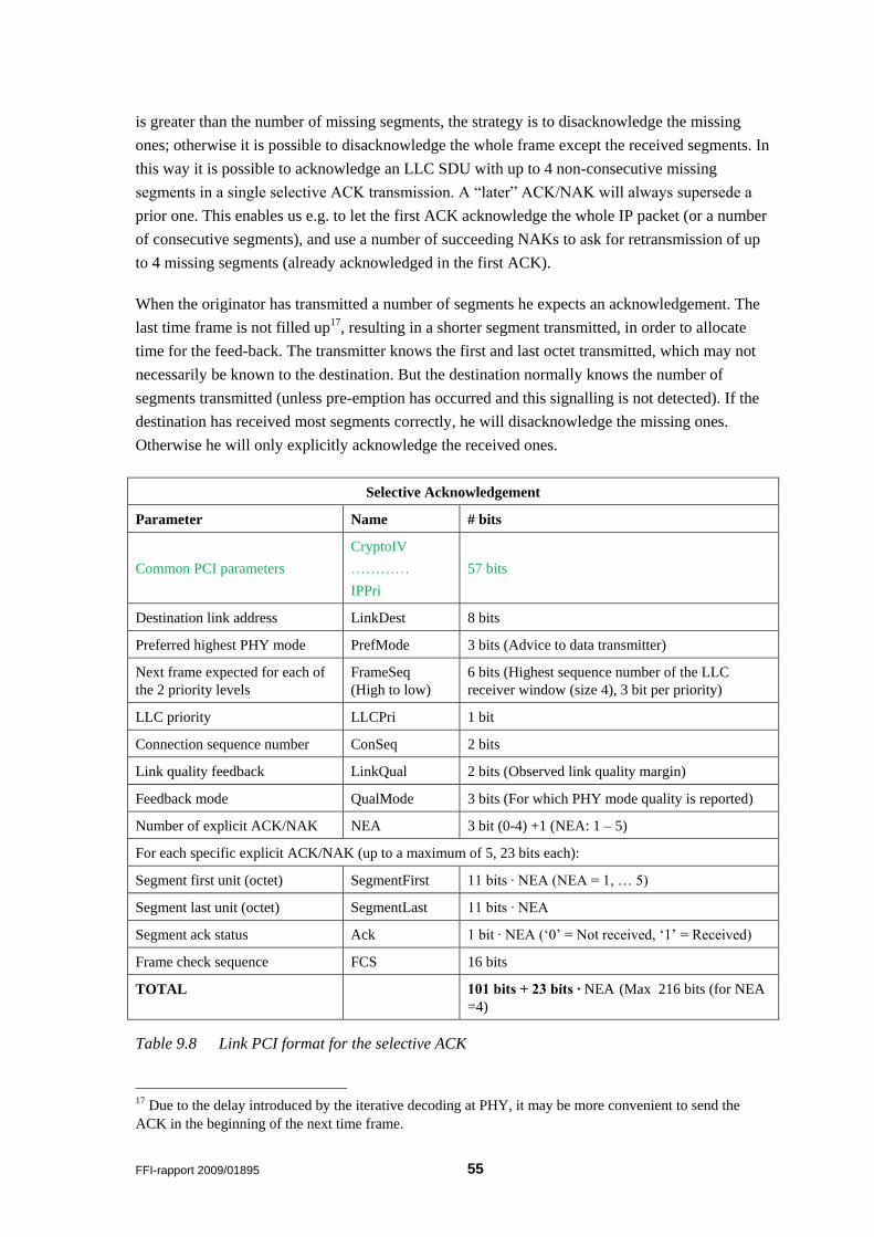
FFI-rapport 2009/01895 55
is greater than the number of missing segments, the strategy is to disacknowledge the missing
ones; otherwise it is possible to disacknowledge the whole frame except the received segments. In
this way it is possible to acknowledge an LLC SDU with up to 4 non-consecutive missing
segments in a single selective ACK transmission. A “later” ACK/NAK will always supersede a
prior one. This enables us e.g. to let the first ACK acknowledge the whole IP packet (or a number
of consecutive segments), and use a number of succeeding NAKs to ask for retransmission of up
to 4 missing segments (already acknowledged in the first ACK).
When the originator has transmitted a number of segments he expects an acknowledgement. The
last time frame is not filled up17, resulting in a shorter segment transmitted, in order to allocate
time for the feed-back. The transmitter knows the first and last octet transmitted, which may not
necessarily be known to the destination. But the destination normally knows the number of
segments transmitted (unless pre-emption has occurred and this signalling is not detected). If the
destination has received most segments correctly, he will disacknowledge the missing ones.
Otherwise he will only explicitly acknowledge the received ones.
Selective Acknowledgement
Parameter Name # bits
Common PCI parameters
CryptoIV
…………
IPPri
57 bits
Destination link address LinkDest 8 bits
Preferred highest PHY mode PrefMode 3 bits (Advice to data transmitter)
Next frame expected for each of
the 2 priority levels
FrameSeq
(High to low)
6 bits (Highest sequence number of the LLC
receiver window (size 4), 3 bit per priority)
LLC priority LLCPri 1 bit
Connection sequence number ConSeq 2 bits
Link quality feedback LinkQual 2 bits (Observed link quality margin)
Feedback mode QualMode 3 bits (For which PHY mode quality is reported)
Number of explicit ACK/NAK NEA 3 bit (0-4) +1 (NEA: 1 – 5)
For each specific explicit ACK/NAK (up to a maximum of 5, 23 bits each):
Segment first unit (octet) SegmentFirst 11 bits ∙ NEA (NEA = 1, … 5)
Segment last unit (octet) SegmentLast 11 bits ∙ NEA
Segment ack status Ack 1 bit ∙ NEA („0‟ = Not received, „1‟ = Received)
Frame check sequence FCS 16 bits
TOTAL 101 bits + 23 bits ∙ NEA (Max 216 bits (for NEA
=4)
Table 9.8 Link PCI format for the selective ACK
17 Due to the delay introduced by the iterative decoding at PHY, it may be more convenient to send the
ACK in the beginning of the next time frame.
56 FFI-rapport 2009/01895
PrefMode indicates the PHY mode that is preferred by the receiver. This may be used to indicate
that a lower mode should be used due to poor link margin, or that a higher mode could be used to
speed up the transfer.
FrameSeq is the next expected LLC sequence number according to the sliding window protocol,
for all 4 priority levels. (If this is found to be useful)
LLCPri is the priority of the LLC PDU related to this segment.
LLCSeq is the LLC sequence number related to this segment. (Not needed if FrameSeq is used.)
LinkQual is a feedback to the transmitter on the observed link quality margin.
QualMode indicated which PHY mode the LinkQual feedback is related to.
NEA indicates the number of (maximum 5) explicit segment (dis)acknowledgements included in
this ACK message.
For each individual explicit ACK/NAK the following parameters are given:
SegmentFirst is the first octet number of the current segment.
SegmentLast is the last octet number of the current segment.
Ack indicates whether this segment has been received correctly or not.
9.5 Link PCI of frames used for multicast voice service
Multicast voice is a service that requires a reservation phase before voice may be transmitted. In
order for nodes to listen in without detecting the reservation, each transmission includes sufficient
PCI to enable this.
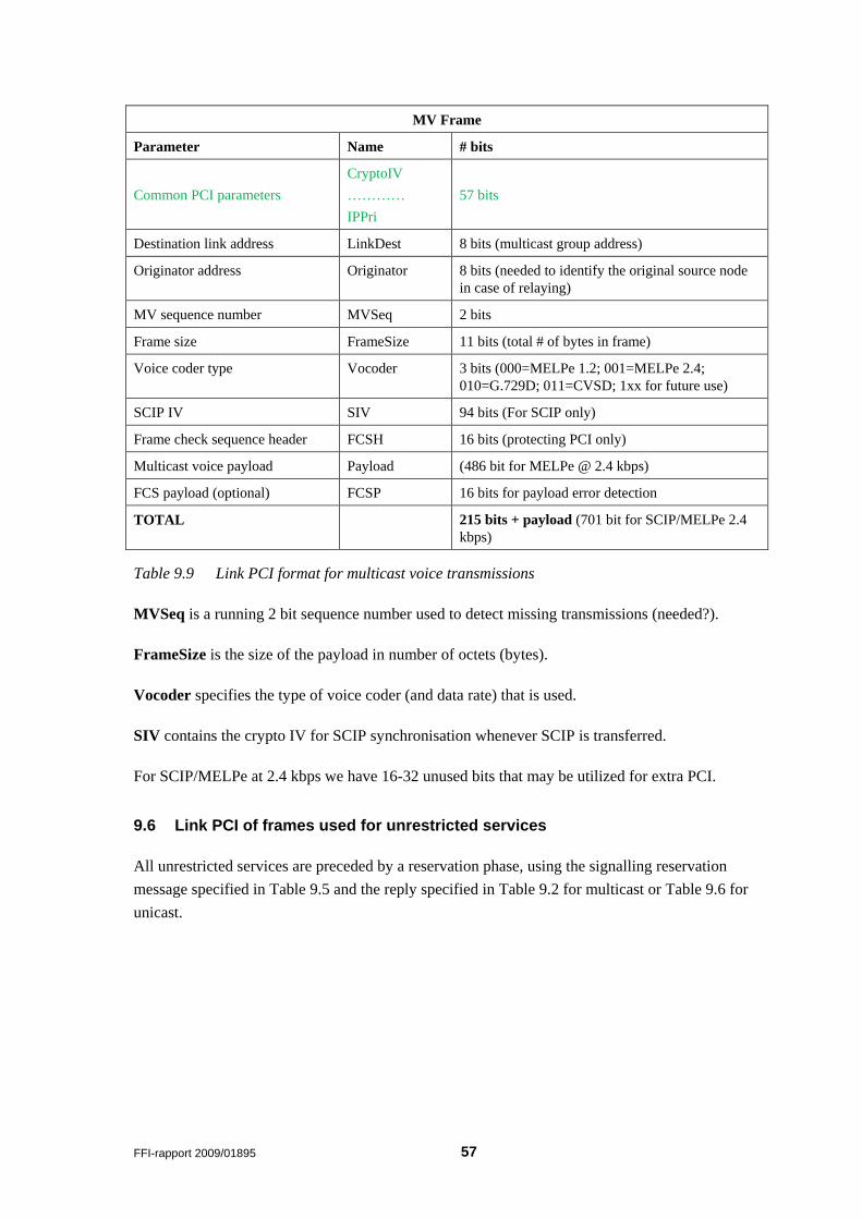
FFI-rapport 2009/01895 57
MV Frame
Parameter Name # bits
Common PCI parameters
CryptoIV
…………
IPPri
57 bits
Destination link address LinkDest 8 bits (multicast group address)
Originator address Originator 8 bits (needed to identify the original source node
in case of relaying)
MV sequence number MVSeq 2 bits
Frame size FrameSize 11 bits (total # of bytes in frame)
Voice coder type Vocoder 3 bits (000=MELPe 1.2; 001=MELPe 2.4;
010=G.729D; 011=CVSD; 1xx for future use)
SCIP IV SIV 94 bits (For SCIP only)
Frame check sequence header FCSH 16 bits (protecting PCI only)
Multicast voice payload Payload (486 bit for MELPe @ 2.4 kbps)
FCS payload (optional) FCSP 16 bits for payload error detection
TOTAL 215 bits + payload (701 bit for SCIP/MELPe 2.4
kbps)
Table 9.9 Link PCI format for multicast voice transmissions
MVSeq is a running 2 bit sequence number used to detect missing transmissions (needed?).
FrameSize is the size of the payload in number of octets (bytes).
Vocoder specifies the type of voice coder (and data rate) that is used.
SIV contains the crypto IV for SCIP synchronisation whenever SCIP is transferred.
For SCIP/MELPe at 2.4 kbps we have 16-32 unused bits that may be utilized for extra PCI.
9.6 Link PCI of frames used for unrestricted services
All unrestricted services are preceded by a reservation phase, using the signalling reservation
message specified in Table 9.5 and the reply specified in Table 9.2 for multicast or Table 9.6 for
unicast.
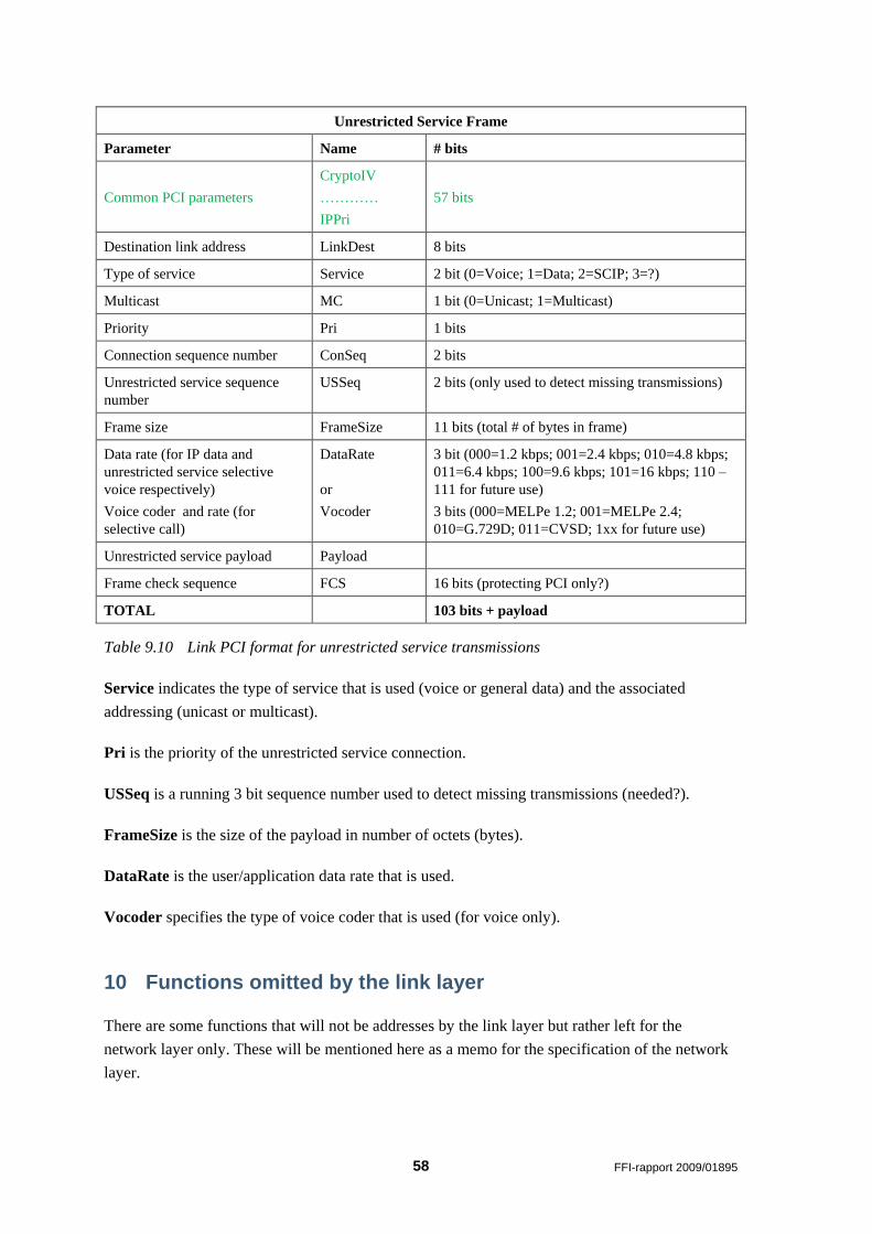
58 FFI-rapport 2009/01895
Unrestricted Service Frame
Parameter Name # bits
Common PCI parameters
CryptoIV
…………
IPPri
57 bits
Destination link address LinkDest 8 bits
Type of service Service 2 bit (0=Voice; 1=Data; 2=SCIP; 3=?)
Multicast MC 1 bit (0=Unicast; 1=Multicast)
Priority Pri 1 bits
Connection sequence number ConSeq 2 bits
Unrestricted service sequence
number
USSeq 2 bits (only used to detect missing transmissions)
Frame size FrameSize 11 bits (total # of bytes in frame)
Data rate (for IP data and
unrestricted service selective
voice respectively)
Voice coder and rate (for
selective call)
DataRate
or
Vocoder
3 bit (000=1.2 kbps; 001=2.4 kbps; 010=4.8 kbps;
011=6.4 kbps; 100=9.6 kbps; 101=16 kbps; 110 –
111 for future use)
3 bits (000=MELPe 1.2; 001=MELPe 2.4;
010=G.729D; 011=CVSD; 1xx for future use)
Unrestricted service payload Payload
Frame check sequence FCS 16 bits (protecting PCI only?)
TOTAL 103 bits + payload
Table 9.10 Link PCI format for unrestricted service transmissions
Service indicates the type of service that is used (voice or general data) and the associated
addressing (unicast or multicast).
Pri is the priority of the unrestricted service connection.
USSeq is a running 3 bit sequence number used to detect missing transmissions (needed?).
FrameSize is the size of the payload in number of octets (bytes).
DataRate is the user/application data rate that is used.
Vocoder specifies the type of voice coder that is used (for voice only).
10 Functions omitted by the link layer
There are some functions that will not be addresses by the link layer but rather left for the
network layer only. These will be mentioned here as a memo for the specification of the network
layer.
FFI-rapport 2009/01895 59
10.1 Packet buffering
Our proposal is that packet buffering mainly resides in the network layer. This is due to the fact
that in a dynamic narrowband network the status of links can change rapidly. If a packet is routed
at the network layer and then is buffered for some time at the link layer, the selected route may
not necessarily be valid any more at the time of transmission. For this reason we have proposed
that the link layer handles a maximum of 2 LLC SDUs at any time. In case of 2, one must be a
high priority SDU that pre-empts an SDU of lower priority. The normal case then will be that
LLC handles only one packet at any time.
10.2 Concatenation
Due to the high initial cost of the reservation process normally required prior to transmitting an IP
packet, the transmission of a single small IP packet is inefficient. If a radio node has many small
IP packets for transmission, efficiency can be substantially increased by concatenation a number
of IP packets to use a single common reservation. In order to maintain fairness, a maximum size
of such a transmission must be set (e.g. to 1500 bytes).
The concatenation task would normally be assigned to the link layer (LLC), but due to the packet
buffering decision above, this process should also reside in the network layer. The network layer
is only allowed to concatenate packets destined to the same link destination. Also, there should be
constraints on the concatenation of packets with different priority.
10.3 Lifetime
The IPv4 protocol has defined a PCI field called Time To Live (TTL). This is normally set to 127
or 255 seconds by the originator, and is the total time the packet is allowed to reside in the
network. Each router will decrement this field by the number of seconds the packet has resided in
the router, but rounded up to 1 if time is less than 1 second. In practice this has become purely a
hop counter where all routers decrement it by 1. When this field reaches 0 the packet is discarded.
In IPv6 the TTL field is replaced by a Hop Limit.
Within the radio subnet, where delays normally are much longer than in fixed, deployable or
tactical backbone networks, we need a separate Lifetime field in addition to the TTL. Each
packet that enters the radio subnet will be given a maximum time of e.g. 60 seconds to live. The
remaining lifetime will be transferred as a part of the intra-network protocol control information
at layer 3a. When this lifetime expires, the radio (where the packet is located) will discard the
packet. This is an intranet function only, and a packet traversing several radio networks will be
given a fresh lifetime every time it enters a new radio network. Lifetime will only be checked
(and updated) at the network level. But within a radio system (node) it is possible to implement a
function that transfers the remaining lifetime to the link layer (through the Interface Control
Information – ICI) so that the link layer may discard a packet if lifetime expires when the packet
is waiting to be transmitted. Such an internal function is not part of the standard.
60 FFI-rapport 2009/01895
11 Summary
Current NATO standards for tactical communications in VHF and UHF (STANAG 4204 and
4205) are not suitable for future use, and are to be replaced by a series of STANAGs termed
NarrowBand WaveForm (NBWF). The production of NBWF has been an important task of
former NATO SC/6 – AHWG/2 and will continue to be so of its successor group, the Line Of
Sight communications (LOS) Capability Team (CaT) under the Communication and Information
Services Capability Panel (CaP/1 CIS) of NATO C3B.
Based upon a physical layer draft STANAG produced by CRC (Canada), FFI has taken on the
task of proposing the link layer protocols for NBWF. This document is a first attempt to describe
the link layer. The description is not complete and is still open for improvement on a number of
items. It attempts to present the background for the proposed solution and work as a discussion
document in the working group.
The report attempts to state the basis for the link layer proposal and also gives a short description
of the physical layer proposal [2] on which it rests. A short discussion on security architecture is
given, and the air interface encryption is adopted as a part of the link layer. The document
describes the services to be offered to the network layer, of which multicast voice and IP data are
considered to be the most important. In order to be able to support multicast voice in a proper
manner, the link layer has, to a large extent, been influenced by the requirements imposed by this
service. The TDMA slot and frame sizes are chosen as a compromise between voice delay and IP
data transport efficiency.
It has not been the intention to present a final specification for the link layer. The description
given in this report is not complete and is still open for improvement on a number of items. A
number of parameters are only listed by their temporary guiding values, awaiting final
specification based on simulation studies. Neither does the report specify all details, but tries to
present the background for the proposed solution. It also presents several system internal details
and algorithms that are not part of a standard specification, although much of this will probably
be included in the STANAG as implementation guidelines.
The report is intended as a discussion document in the working group (CaP/1 CIS– LOS CaT)
and should work as a foundation for producing the final NBWF Link Layer STANAG. The
NBWF STANAG may end up with a small number of variants, of which this document has
focused on the land tactical variant termed NBWF(L). Other variants will probably differ only in
parameter values and lack of or simplified functionality. This report will not be updated with a
final description. All future work will be documented in the NBWF Link Layer STANAG.

FFI-rapport 2009/01895 61
Abbreviations
ACK ACKnowledgement
AES Advanced Encryption Standard
AIE Air Interface Encryption
ARQ Automatic Repeat reQuest
BER Bit Error Rate
CATA Collision Avoidance Time Allocation
CAS CArrier Sense
CC Connect Confirm
CCI COMSEC Controlled Item
COMSEC COMmunications SECurity
CPM Continuous-Phase coded Modulation
CR Connect Request
CRC Communications Research Centre Canada
CRC Cyclic Redundancy Check
CSMA Carrier Sense Multiple Access
dBm desiBel milliwatt
DC Disconnect Confirm
DR Disconnect Request
DU Dual Use (voice and data)
EMCON EMissions CONtrol
EPM Electronic Protection Measures
FCS Frame Check Sequence (error detection)
FFI Forsvarets Forskningsinstitutt (Norwegian Defence Research Establishment)
FEC Forward Error Correction
GCR General CR
GDR General DR
ICI Interface Control Information
IP Internet Protocol
IPSec Internet Protocol Security
IV Initialisation Vector
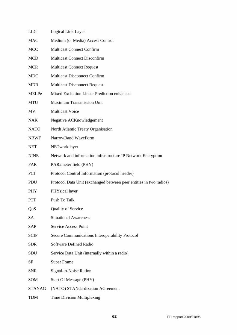
62 FFI-rapport 2009/01895
LLC Logical Link Layer
MAC Medium (or Media) Access Control
MCC Multicast Connect Confirm
MCD Multicast Connect Disconfirm
MCR Multicast Connect Request
MDC Multicast Disconnect Confirm
MDR Multicast Disconnect Request
MELPe Mixed Excitation Linear Prediction enhanced
MTU Maximum Transmission Unit
MV Multicast Voice
NAK Negative ACKnowledgement
NATO North Atlantic Treaty Organisation
NBWF NarrowBand WaveForm
NET NETwork layer
NINE Network and information infrastructure IP Network Encryption
PAR PARameter field (PHY)
PCI Protocol Control Information (protocol header)
PDU Protocol Data Unit (exchanged between peer entities in two radios)
PHY PHYsical layer
PTT Push To Talk
QoS Quality of Service
SA Situational Awareness
SAP Service Access Point
SCIP Secure Communications Interoperability Protocol
SDR Software Defined Radio
SDU Service Data Unit (internally within a radio)
SF Super Frame
SNR Signal-to-Noise Ration
SOM Start Of Message (PHY)
STANAG (NATO) STANdardization AGreement
TDM Time Division Multiplexing
FFI-rapport 2009/01895 63
TDMA Time Division Multiple Access
TTL Time To Live
Tx Transmit
UCC Unicast Connect Confirm
UCD Unicast Connect Disconfirm
UDC Unicast Disconnect Confirm
UHF Ultra High Frequency (military UHF-band 1: 225 – 400 MHz)
UM Unrestricted Mode
VHF Very High Frequency (military VHF-band: 30 – 88 (108) MHz)
XOFF Transmitter Off (stop-and-wait)
64 FFI-rapport 2009/01895
Bibliography
[1] "Requirements for a Narrowband Waveform,"AC/322(SC/6-AHWG/2)M(2008)0003,
Aug.2008.
[2] "Technical standards for narrowband physical layer of the NATO networking enabled
communications waveform and VHF propagation models (Draft 4)," SC/6 - AHWG/2:
March 2010.
[3] V. Jodalen, B. Solberg, and S. Haavik, "NATO Narrowband Waveform (NBWF) -
overview of link layer design,"FFI-rapport 2009/01894, 2011.
[4] L. E. Bråten, M. Hauge, J. E. Voldhaug, and K. Øvsthus, "Medium access for narrowband
wireless ad-hoc networks; requirements and initial approaches,"FFI-rapport 2008/01313,
June2008.
[5] L. E Bråten, J. E. Voldhaug and K. Øvsthus, “Medium access for a military narrowband
wireless ad-hoc network; requirements and initial approaches”, MILCOM 2008
[6] STANAG 4591, “Narrow Band Voice Coder”, NATO 2002
[7] C. Brown and P. J. Vigneron, ” Spectrally Efficient CPM Waveforms for Narrowband
Tactical Communications in Frequency Hopped Networks.”, MILCOM 2006
[8] F. Y. Li, A. Hafslund, M. H. Hauge, P. Engelstad, Ø. Kure and P. Spilling, ” Does Higher
Datarate Perform Better in IEEE 802.11-based Multihop Ad Hoc Networks?”, Journal of
Communications and Networks, Vol. 9, Sept. 2007
[9] Zhenyu Tang and J. J. Garcia-Luna-Aceves, “A Protocol for Topology-Dependent
Transmission Scheduling in Wireless Networks”, IEEE 1999


![[MS-ASHTTP]: Exchange ActiveSync: HTTP Protocol... · Hypertext Transfer Protocol (HTTP) Hypertext Transfer Protocol over Secure Sockets Layer (HTTPS) Secure Sockets Layer (SSL) XML](https://img.pdfslide.us/doc/110x75/5fc28633cc0d714b7a690f25/ms-ashttp-exchange-activesync-http-protocol-hypertext-transfer-protocol.jpg)