Embed Size (px)
Citation preview
Design of a Secure Network Management System
Tim Terlegård
LiTH-ISY-EX-3196-2002
2002-03-12


Design of a Secure Network Management System
Examensarbete utfört i datorteknik
vid Linköpings tekniska högskola
av
Tim Terlegård
LiTH-ISY-EX-3196-2002
2002-03-12
Handledare: Erik Forsberg
Examinator: Viiveke Fåk
Linköping 2002-02-12


Avdelning, InstitutionDivision, Department
Institutionen för Systemteknik581 83 LINKÖPING
DatumDate2002-02-12
SpråkLanguage
RapporttypReport category
ISBN
Svenska/SwedishX Engelska/English
LicentiatavhandlingX Examensarbete
ISRN LITH-ISY-EX-3196-2002
C-uppsatsD-uppsats
Serietitel och serienummerTitle of series, numbering
ISSN
Övrig rapport____
URL för elektronisk versionhttp://www.ep.liu.se/exjobb/isy/2002/3196/
TitelTitle
Design av ett säkert nätverksövervakningssystem
Design of a Secure Network Management System
Författare Author
Tim Terlegård
SammanfattningAbstractThe size and complexity of local area and wide area networks are continually growing and so dothe requirements of high availability. Today we rely on the technology and it should always work.Network management is therefore getting more and more important. Network managementincludes: monitoring and isolating faults, measuring performance, configuring the resources,making sure the network is secured and more.
Since in the early 1990s the management has typically been done with SNMPv1 or CMIP andusing the client/server model. SNMPv1 is insecure, CMIP is complex and the traditionalcentralized paradigm is no longer sufficient to handle the management requirements of largenetworks.
As the demands for security and flexibility increases, new ways to manage networks are needed.This research tries to find out how a network management system should function, whatmanagement protocol to use, how to enhance the flexibility and how to make the system moresecure.
NyckelordKeywordnetwork management, mobile agents, SNMP, CMIP, design, JMX, jiro, CIM, WBEM, WBM,RMON, MIB


Table of Contents1 Introduction ......................................................................................................1
1.1 Assignment..............................................................................................1
2 Network Management Basics..........................................................................3
2.1 Why is There Network Management?.....................................................32.2 Who Needs Network Management?........................................................42.3 What is Network Management?..............................................................52.4 Network Management Architecture.........................................................72.5 Network Management Technologies.......................................................9
3 Network Management Details.......................................................................11
3.1 Fault Management.................................................................................113.2 Configuration Management...................................................................123.3 Security Management............................................................................133.4 Performance Management.....................................................................143.5 An Advanced Network Management System........................................153.6 Distribution Models...............................................................................21
4 Security............................................................................................................25
4.1 What is Security?...................................................................................254.2 Firewalls.................................................................................................294.3 Virtual Private Network.........................................................................334.4 A Secured Network Management System.............................................41
5 Network Management Protocols...................................................................45
5.1 SNMPv1................................................................................................455.2 SNMPv2................................................................................................495.3 SNMPv3................................................................................................505.4 RMON...................................................................................................595.5 CMIS/CMIP...........................................................................................64
6 Enhanced Network Management Technologies..........................................67
6.1 Mobile Agents.......................................................................................676.2 Web-based Management........................................................................726.3 Web-based Enterprise Management......................................................736.4 Java Management Extensions................................................................75
v

7 Existing Software for Network Management..............................................79
7.1 Syslog....................................................................................................797.2 Jini..........................................................................................................827.3 Jiro.........................................................................................................837.4 UDDI and WSDL..................................................................................86
8 Discussion and Conclusions...........................................................................89
8.1 Protocols................................................................................................898.2 Technologies..........................................................................................898.3 Programming Language.........................................................................918.4 Software.................................................................................................918.5 Services..................................................................................................928.6 NOIMIS.................................................................................................928.7 Network Management............................................................................94
9 Suggested Design............................................................................................97
9.1 Security..................................................................................................979.2 Overview................................................................................................989.3 Design of Modules.................................................................................99
A. List of Acronyms ........................................................................................157
B. List of Free Tools for Network Management...........................................161
Glossary............................................................................................................163
References........................................................................................................167
vi

List of Tables3-1. Classification of distribution models by numbers........................................214-1. Average time required for exhaustive key search........................................407-1. Syslog priorities...........................................................................................809-1. Methods in Lookup class...........................................................................1069-2. Methods in Join class.................................................................................1089-3. Methods in Discover class.........................................................................1099-4. Methods in Info class.................................................................................1109-5. Methods in LookupStorage class...............................................................1119-6. Methods in EventHandler class.................................................................1169-7. Methods in EventStorage class..................................................................1199-8. Methods in EventLogging class.................................................................1239-9. Methods in LoggingStorage class..............................................................1269-10. Methods in History class..........................................................................1319-11. Methods in HistoryStorage class.............................................................1329-12. Methods in ProtocolProxy class..............................................................1359-13. Methods in SNMPv1 class.......................................................................1369-14. Methods in Statistics class.......................................................................1419-15. Methods in Monitoring class...................................................................1439-16. Methods in Client class............................................................................1479-17. Methods in Events class...........................................................................1489-18. Methods in Node class.............................................................................1499-19. Methods in DistributedService class........................................................1519-20. Methods in Scheduler class......................................................................1529-21. Methods in NOIMIS class.......................................................................1539-22. Methods in ReportProducer class............................................................154
List of Figures2-1. Complexity due to that everything should work together..............................32-2. A simple network management system.........................................................93-1. An advanced network management system.................................................163-2. Proxy converting SNMP to CMIP................................................................203-3. Proxy decrypting AES-encrypted SNMPv1 traffic......................................20
vii

3-4. Different distribution models.......................................................................224-1. Eavesdropping by a third part......................................................................274-2. Firewall protecting a network......................................................................324-3. Example of a Virtual Private Network.........................................................344-4. IPSec in transport mode...............................................................................354-5. IPSec tunneling in transport mode...............................................................364-6. IPSec in tunnel mode...................................................................................374-7. IPSec tunneling in tunnel mode...................................................................374-8. A network management system secured by a firewall and VPN.................425-1. An SNMPv1 message inside........................................................................465-2. The SNMP PDU inside................................................................................465-3. The SNMP PDU inside................................................................................485-4. SNMPv3 entity architecture.........................................................................515-5. SNMPv3 subsystem architecture.................................................................515-6. SNMPv3 security subsystem architecture...................................................525-7. SNMPv3 access control subsystem architecture.........................................525-8. SNMPv3 message format............................................................................535-9. RMON tree..................................................................................................616-1. The mobile agents based network management infrastructure....................676-2. Embedded Web-Based Management...........................................................726-3. WBEM architecture.....................................................................................746-4. JMX architecture..........................................................................................757-1. The syslog system logging utility................................................................807-2. Jiro architecture............................................................................................847-3. Jiro and JMX working together...................................................................859-1. Inheriting from DistributedService and ReportProducer.............................979-2. The network management system architecture............................................999-3. General structure and communication among the classes.........................1009-4. General structure among the classes, network adapters added..................1009-5. The steps in a Lookup service....................................................................1019-6. The steps in a Lookup service with authentication....................................1029-7. ER-diagram for the Lookup database........................................................1049-8. The class structure and communication for the Lookup module...............1059-9. Collaboration diagram of what happens when a client wants to use a
service........................................................................................................1139-10. Collaboration diagram of a device registering itself................................1139-11. ER-diagram for the Event Handler database...........................................115
viii

9-12. The class structure and communication for the Lookup module.............1169-13. Collaboration diagram for a scheduled poll.............................................1209-14. ER-diagram for the Event Logging database...........................................1229-15. The class structure and communication for the Event Handler module..1239-16. Collaboration diagram showing when Event Handler logs an event.......1299-17. ER-diagram for the history database.......................................................1319-18. The class structure and communication for the History module.............1319-19. A collaboration diagram showing how to use the History Service..........1339-20. The class structure and communication for the Protocol Proxy module.1359-21. Collaboration diagram converting SNMPv3 to SNMPv1........................1369-22. Monitor database showing only the polling part......................................1399-23. The class structure and communication for the Monitoring module.......1409-24. Collaboration diagram for a scheduled poll.............................................1459-25. The class structure and communication for the Client module...............1469-26. Collaboration diagram showing when the client receives an event.........1509-27. Collaboration diagram showing when the client receives an ack............150
ix

x
PrefaceThe size and complexity of local area and wide area networks are continuallygrowing and so do the requirements of high availability. Today we rely on thetechnology and it should always work. Network management is therefore gettingmore and more important. Network management includes: monitoring andisolating faults, measuring performance, configuring the resources, making surethe network is secured and more.
Since in the early 1990s the management has typically been done with SNMPv1or CMIP and using the client/server model. SNMPv1 is insecure, CMIP iscomplex and the traditional centralized paradigm is no longer sufficient tohandle the management requirements of large networks.
As the demands for security and flexibility increases, new ways to managenetworks are needed. This research tries to find out how a network managementsystem should function, what management protocol to use, how to enhance theflexibility and how to make the system more secure. The main target platformfor the resulting network management system is Solaris and GNU/Linux andshould be developed using C or C++. Although Java is not intended as theimplementation programming language, it is still not ignored in this work. Thereare interesting Java solutions for network management and perhaps Java as aprogramming language is in discussion for implementation later on.
This Document’s AudienceAnyone who wants to know more about network management are welcome totake part of this document. You are expected to have knowledge of hownetworks work. This thesis report can not explain everything from the verybasics, so some knowledge about TCP/IP is good, especially to get a fullunderstanding of theSecuritychapter. TCP/IP knowledge is not required for theother parts of the document, but as it is about managing networks, one shouldknow what networks are, what they do and why we use them.
i

Preface
Tools Used When Making This DocumentThis document has been written with DocBook. DocBook is a DTD for eitherSGML or XML, SGML being the one used in this document, but the differencesare small. DocBook specifies only contents, not layout. You use stylesheets toget the layout you want. What is good with this is that you can choose anystylesheet you want for your document and the layout is changed. The mostcommon DocBook package is OpenJade, which can be found at [OJADE]. Theuse of SGML also makes DocBook very portable, the source of this documentcan be read by any operating system.
There are also a number of images in this document. Most of them are drawnwith the toolDia, which can be found at [DIA]. There are a few images that arecopied from other web pages and permission for using them is granted by thecopyright holders. Thanks toSunandNetQoSfor allowing me to use them.
Others Involved in This WorkThis assignment or thesis was assigned to me by Erik Forsberg at a companyPOSS (Portable Open Software Solutions) in Sweden. He’s also been mysupervisor, given me ideas and provided lots of feedback. I have also had anexaminer, Viiveke Fåk, who also has been providing me with some feedback.
Outline of This documentThis chapter serves as an introduction to the entire document. A brief descriptionof the remaining chapters follows.
Chapter 1 IntroductionThe reader gets introduced to this thesis.
ii

Preface
Chapter 2 Network Management BasicsThis chapter Introduces the reader to Network Management. It explains whatnetwork management is, why it is used and why it is needed.
Chapter 3 Network Management DetailsSo know we know what network management is. But how do we make one?What services must it provide? This chapter discusses how to build a networkmanagement system and how it should solve the system’s tasks. The ideas heremainly come from the author himself.
Chapter 4 SecurityWhen it comes to computers, security is mostly involved in some way andnetwork management is no exception. The chapter explains what security is,why it is needed in a network management system and how to implement it.
Chapter 5 Network Management ProtocolsThree different network management protocols are described, those that aremost common today. You get to know how they are designed and how they workin a network management system.
Chapter 6 Enhanced Network ManagementTechnologies
This chapter examines what other network technologies, other than protocols,that can be useful in a network management system. To make a good networkmanagement system you need more than just a good protocol, especially if thesystem should provide high flexibility and availability.
iii

Preface
Chapter 7 Existing Software for NetworkManagement
When you develop something you might not have to develop every part of thesystem from scratch. There might be software packages available that can beused in the new system. Tree different software packages, that can help inbuilding a network management system, are described here.
Chapter 8 Discussion and ConclusionsChapter 8 forms a summary of the former chapters. It also presents whatprotocols, technologies, software and programming languages that has beenchosen to the network management system designed in this work.
Chapter 9 DesignA detailed design specification of a complete network management system, theway the author thinks it should be, is presented here. This is the final result ofthe thesis.
Appendix A List of AcronymsA list of acronyms used in this document.
Appendix B List of Free Tools for NetworkManagement
A list of free network management software that can be used to sniff networks,check status of network elements and other network management relatedsoftware.
iv

1 IntroductionNetworks are of growing importance and have become critical in the businessworld. Networks are getting more and more complex and heterogenous, i.e.different types of networks (computer networks, telephone networks, mobilecellular networks and others) are working together. It is not just the publicnetworks that grow and gets more complex, but also within organizations.Organizations want to take advantage of the technology and they build complexnetworks. As the networks become larger and more complex and heterogenous,the costs rise. In spite of the networks being complex, the demands are still veryhigh, they should or must work 24 hours a day. It is a big challenge to have allservices running and offer good quality of service (QoS). This is why networkmanagement systems are needed. They discover faults and errors in networksand sometimes correct them, they discover performance issues, they secure thenetwork, they ease the configuration of the network and more. This makes oneable to catch network failures before they are too critical. In short, a networkmanagement system monitors the health of the network. If something goeswrong, network engineers are alerted and the problem is hopefully fixed beforethe network users notice any problems.
1.1 AssignmentThe goal of this thesis is to design a flexible and secure network managementsystem (NMS) that is distributed (increases scalability and reliability) andincludes most features a good network management system should have. Thesystem should fit in both small companies and enterprises. The system should bedivided into separate packages or modules so that one can choose what servicesto use. The Network management systems that exist today are often expensive,proprietary, complex, lack important features (such as security) or arecentralized.
Network management includes management for charging users by traffic usage,but that will not be a part of this thesis. During this work mostly internal use incompanies have been in mind, i.e. companies that wants network managementsystems to manage their networks and lighten up the burden of the network
1

Chapter 1 Introduction
engineers. As users typically have free access to the internal network and oftenalso to the Internet, no investigation about charging is made in this thesis, butbecause of the flexible design there should be no problem to add this later on.
2

2 Network Management BasicsThis chapter is an introduction to network management. It explains whatnetwork management is, who needs it and why.
2.1 Why is There Network Management?There are several types of networks, some of them transport data. The two mainnetworks that can transport data are the computer networks andtelecommunication networks. The telecom networks are very reliable. You cancall anyone, anytime, from anywhere to anywhere in the world and be almostsure that you get connected to the destination. The computer networks are notequally reliable because of several things. Computer technology is morecomplicated than telephone services. Computer communication is mostly packetswitched and there is therefore no guarantee that you get a certain amount ofbandwidth. The telecommunications network, however, use circuit switchedmessages and therefore guarantees a certain amount of bandwidth. Further, thetelephone industry all over the world has been monopolistic andsingle-vendored. This is not the case anymore (e.g. 1984, AT&T split up in theUS and there were all of a sudden 1500 telephone service providers) and thetelecommunication networks are also multi-vendored and heterogenous withcomplexity increasing because of new services are being developed. Computernetworks were multi-vendored from the start. The computer technology also hasmore rapid standardization processes and development cycles compared to thetelecommunication (where ITU-T is the standardization organization).
Figure 2-1illustrates the complexity of computer technology and as thecomputer networks, telecommunication networks and also mobile cellularnetworks are merging, the complexity grows even more. For example, one canbrowse the Web using the telephone wires and one can dial someone from acomputer.
3

Chapter 2 Network Management Basics
Figure 2-1. Complexity due to that everything should work together.
A network can be very complex and it must often perform well and be secure.But how can one know about the health of a network? How can one know that itperforms well and that it is secure? One solution is to do these checks manually.For example, one can ping the network devices to get their respond times. Onecan manually scan the network for security vulnerabilities. This will be tediousand error prone work, especially in a large network. Maintaining a networkincludes very many tasks and performance and security checks must be maderegularly. This is why network management is needed. Introducing a networkmanagement system to a network automates most of the network managementtasks and makes other tasks easier to perform. If there was only one network, forinstance the computer network, we would still need network management. Butdue to the complexity and that people have high demands (everything shouldalways work), network management gets more and more important.
2.2 Who Needs Network Management?Almost any enterprise makes use of an internal network. If a company connectsits computers together in a network environment, then a management system isprobably needed. When a network fails, or shows poor performance, the costs
4
Chapter 2 Network Management Basics
can be enormous, productivity of employees can suffer, dissatisfaction amongusers and customers could cause other problems. If cost of ownership, reliability,performance and availability matter, an organization will probably need anetwork management system.
2.3 What is Network Management?Managing a network device could for instance be to check the status of a printer- is it out of paper? Is it functioning? For a device, for instance the printer, to bemanageable it must have anagentrunning. An agent is a software processlistening for messages. When the agent receives a message it performs the actiondescribed by the message.
International Organization for Standardization (ISO) divides networkmanagement into five areas: fault, configuration, performance, security andaccounting management. These are described below.
2.3.1 Fault ManagementWhenever a service or network device fails, the management system shall detectthe fault, find the cause and report the failure. In some cases the managementsystem can also restore the service automatically, but most often a networkoperator has to fix the fault manually. The goal of fault management is toincrease the network reliability, discover failures as quickly as possible so anetwork operator can fix the problem, hopefully even before the network’s usersnotices there is a problem.
2.3.2 Configuration ManagementConfiguration management is the process of gathering data from the networkand modifying the setup of the network devices. It also involves storing theobtained data and producing reports based on the data.
5

Chapter 2 Network Management Basics
2.3.3 Security ManagementSecurity management enables the network engineer to control access to serviceswith the purpose of protecting sensitive information from unauthorized access.That is according to Conroy et al. [CON96]. But it should also includeprotection against unauthorized modification and addition of information.Unauthorized addition of information can lead to DoS in form of full disks forinstance. The information can also confuse users and it might even be used bysome service and cause unexpected problems. Subramanian [SUB00] means thatsecurity management also includes other areas such as physical security. In thisthesis security management is considered the former definition. This is becausephysical security is not possible to affect from a network managementapplication and possibly the network management engineers are not part of thecompany whose network they manage and might, therefore, not know about thephysical protection. However, operating system security and physical securitystill has to be maintained. If anyone can reach the computer and remove the diskdrive and get the sensitive information that way, the security management cannot prevent unauthorized access. All aspects of computer security has to beapplied to have a secure system - more information about security can be foundin Chapter 4. Security management is thus a part of security, but it does notcover the whole security area.
2.3.4 Performance ManagementPerformance management involves making sure that the network always isaccessible so users can use it efficiently. It involves monitoring the utilizationand error rates of network devices and ensuring that the capacity of the links anddevices is good enough to always offer good performance to the user. With themonitored data the network engineers can determine utilization trends and thenextend the capacity if needed. They can isolate a performance problem to acertain device and hopefully solve it before any users notices any performanceissues. The data can be used to predict peak network utilization; knowing that,you can choose at what times to make the daily scan for software bugs.
6

Chapter 2 Network Management Basics
2.3.5 Accounting ManagementAccounting management enables the network engineer to measure the usage ofnetwork resources. The collected data can be used to check how much trafficevery user has caused and what resources they have used. The engineer cansetup and check user quotas for resources, determine costs and bill users. This istypically used in the telecommunication networks where all users have to pay forthe telephone calls they make.
2.4 Network Management ArchitectureThe structure that all network management architectures use are basically thesame. The main components are:managed devices, agents, networkmanagement protocolsandmanagers.
2.4.1 Managed DevicesManaged devices run software that enables them to send alerts, be configuredand monitored. Managed devices can be anything on a network that has theability to run an agent. More and more devices are nowadays running agents, forexample, there are washing machines running agents. This means that manageddevices can be routers, switches, printers, servers, workstations, PDAs, mobilephones, microwave ovens, DVDs and so on. And if they have agents, they can bemanaged.
2.4.2 AgentsAgents are software running on a device. They mostly act as servers, respondingto requests about their status, but they can also send alarms when they want towarn about something. As the years go by, agents will get more and moresophisticated and the picture of them just behaving as servers is changing slowly.
Often the manufacturer of the managed device provides agents to their products.
7
Chapter 2 Network Management Basics
2.4.3 Network Management ProtocolsProtocols describe the way systems (hardware or software) can communicate. Ifpeople speak different languages they do not understand each other. If twodevices communicate using different protocols they will not understand eachother either. So if a management application wants to manage a device, themanager application and the agent on the device have to use the same protocol.Applications are easy to develop, but the agents are often static and knows onlyone protocol. That makes the choice of protocol critical for both the applicationand the agent. There are several network management protocols in use, SNMPand CMIP being two of them.
2.4.4 ManagersManager is the application that gets information from agents and informs thenetwork engineers of the status of the network.
2.4.5 A Simple Network Management SystemA small and simple network management system typically looks like inFigure2-2. It consists of the four components described above: managed devices,
8

Chapter 2 Network Management Basics
agents located on every device, protocols and a manager.
Figure 2-2. A simple network management system.
2.5 Network Management TechnologiesTo manage a network there are different distribution models to choose from,different protocols and software to use. SNMPv1 has been the most widespreadprotocol in the Internet world and CMIP has been trying to find acceptance in theTelecommunication world. SNMPv1 offers no security and CMIP has not foundthe broad acceptance, mostly due to its complexity and large memory needs.Shortcomings of both these protocols have made the world look for alternatives.As the Internet and telecom networks are merging, it would be desirable to usenetwork management software that handles them both transparently and equallywell. There are several candidates for becoming the new management protocolor technology of choice: SNMPv3, CMIP, JMX, WBM, WBEM and Mobileagents. These are individually discussed inChapter 5andChapter 6.
Java has been a popular programming language for a couple of years. It isplatform independent, objects can be sent from one computer to another, codecan be sent from one computer to another and be executed on the destination. A
9

Chapter 2 Network Management Basics
consequence of platform independence is that more and more devices ship witha Java Virtual Machine (JVM). Any Java program can communicate with anyJava-enabled (has a JVM) device if they are connected to a network. The othertwo aspects (sending objects and code on the network) increase flexibility andare crucial when working with mobile agents. Sun Microsystems offers JiniTechnology, which is based on Java. It makes network management moreflexible as one can easily see what services the network offers. Jini is discussedin Section 7.2. Jiro is another Java software from Sun Microsystems. Its intentionis to make a distributed automated management system. Today’s managementsystems can only monitor the status of devices. This way is a reactive way andJiro provides a more proactive approach. Jiro is explained inSection 7.3.
10

3 Network Management DetailsThis chapter discusses fault, configuration, security and performancemanagement in further detail. Accounting management is not included since it’snot a requirement for this thesis to implement it. After knowing what networkmanagement really is, one can discuss the features a network managementsystem should have. Usable features and distribution models are also discussed.
3.1 Fault ManagementThe primary goal of fault management is to keep the network running withoutany failures. To achieve this, fault management involves the work tocontinuously detect, log, isolate and fix the cause of network problems.
Detecting faults can be done in two ways, logging critical network events orpolling network devices. Most managed devices can send a notification ifsomething goes wrong. Solely relying on such events will, however, notguarantee that the device is functioning. If the device fails it might be unable tosend the event. The device might also be capable of only reporting certain kindsof failures. Because of that polling is a good complement. Polling means higherbandwidth usage and if there are many devices and low bandwidth on thenetwork, polling should not be used too frequently.
Depending on the size of the network, carefully choosing what faults to monitorcan be very important. In a small network the network operator may have time tofix every fault that occur. In larger networks there might only be time toinvestigate the most critical faults and then it is important to configure thenetwork and devices to only notify the network management system of thecritical events. If one or more devices are non-configurable, a filter in themanagement system could filter out the not so important events. The events aresaved in the database, but the client filters out the unimportant events and thenetwork operators can easier grasp the situation.
The form in which the fault is reported is also an important issue. The networkoperators can be notified in several ways: pictures, text, bells and maybe evenvibrations from a pager or mobile phone. A picture is probably the mosteffective way and certainly in combination with different colours meaning
11

Chapter 3 Network Management Details
different faults. Longer text messages explaining what happened and what canbe done to restore the service can be good if the network operator is not familiarwith the network or if the network is large. If the network operators not alwayslook at the screen, bells can be helpful.
3.2 Configuration ManagementThe goals of configuration management are to monitor and store network andsystem configuration information. This information can for instance be versionnumbers of installed software or how the devices are configured. When aproblem occurs, the configuration can be searched for clues that may helpsolving the problem.
Devices that are manageable can also be configured, i.e. there are parametersthat can be changed. For example, a device can be told to shut down or to changea firewall rule. Being able to configure the devices enhances the networkoperators’ control over the network. If the configuration data is stored, then it iseasy to track changes and see what is different in the current configurationcompared to the stored configuration. In some situations it could even be good toautomatically update network configuration with a stored one.
A Database Management System (DBMS) has many advantages over storing incommon ASCII text files. A DBMS is also very efficient when sending reports.You might want information about a device and if it is stored in a database it isvery easy and fast to find compared to using simple text files. Configurationreport is not as critical as fault reports, but sometimes it is necessary, forexample when finding duplicate network addresses. XML has become popularand it is a structured language for data where the data is stored as text. XML hasthe advantage of being just text, so the data is easily transfered betweenmanagement systems and can be read on any platform, no database is needed. Anegative side of XML is that it takes more disk space than databases. Also,searching in databases is much faster than searching in text files.
Configuration data should be confidential. Information about the network andthe setup of the devices can cause harm in many ways if it comes in the hands ofa malicious person. For instance, a third party could monitor what software isrunning on the devices. If any of those have a security hole, the third party can
12

Chapter 3 Network Management Details
use this information to gain access to the network. If the configuration data wasencrypted, this would not happen.
3.3 Security ManagementThe goal of security management is to control access to network resources sothat the network cannot be sabotaged and sensitive information cannot beaccessed without appropriate authorization.
Security management consists of:
• Identifying the sensitive information to be protected.
• Finding the access points.
• Securing the access points.
• Maintaining the secure access points.
Identifying the sensitive information means determining what sensitiveinformation there is on the network and on which hosts it resides. Most servicesuse or offers sensitive information, but there are also services that offer harmlessinformation. When the sensitive information is identified, the next step is to findout how users can access it. This could, for example, be done by port scanningthe resources. The result of this is that you know every access point there is tosensitive information. When you know this, the access points can be secured.The security can be applied by:
• Encrypting the traffic.
• Restricting what traffic can flow on the network, using packet filters.
• Authentication to services.
Usernames, passwords, configuration and other sensitive data flowing on thenetwork should be encrypted and if someone eavesdrops on the wire, theencrypted information would be useless.
The network management system itself can contain sensitive information. Whendetermining the access points to a data network, you should also include thenetwork management system.
13

Chapter 3 Network Management Details
When the access points are secured they have to be maintained. New securitybugs appear constantly and you need to check if your network is vulnerable.There are programs that scan networks for security vulnerabilities and if thenetwork engineer does this every now and then, the risk for intrusion is muchsmaller. New software patches might be released and installing those as soon aspossible is also an important issue when it comes to maintaining the security of anetwork.
3.3.1 FirewallsUsing firewalls (packet filters) you can restrict the traffic flow and only allowcertain hosts or certain services in a LAN to be used from outside the firewall. Ifa device wants to filter packets and protect itself from unauthorized access frominside the LAN, it is easiest and mostly enough to trust the user and/or hostauthentication protection. Computers and other more sophisticated networkdevices can use packet filtering, but it gives the network engineers much moreconfiguration to do and possible headache as well. Packet filtering should onlybe used by the firewall. If there is no firewall protecting the LAN, hostauthentication (see below) on every device can do a part of the job that packetfiltering does. A firewall makes good protection if right configured and havingone or more between the organization’s network (the managed network) and thepublic network (the Internet) is close to mandatory.
3.3.2 AuthenticationIf an unauthorized user tries to access a service, a report can be made and sent tothe network engineers. Statistical reports can be created that shows how manyauthentication failures there are every week. If there are many failures maybesomething should be done, perhaps the firewall rules are not strict enough.Perhaps there is a service they try to use that should not be available. Reportscan be very useful. More about authentication is found inSection 4.1.4.
14

Chapter 3 Network Management Details
3.4 Performance ManagementThe goal of performance management is to measure various aspects of networkperformance so that the network performance can be maintained at an acceptablelevel. Performance management involves three main steps:
1. Gather performance data on variables of interest.
2. The gathered data is analyzed to determine normal levels.
3. Appropriate performance thresholds are determined for each importantvariable so that exceeding these thresholds indicates a network problemworthy of attention.
By analyzing the monitored data one can make graphical representations of theutilization of a network device or link, either it could be in real time or from ahistorical perspective. Line graphs, bar graphs and pie graphs can give a quickand good picture of how the network is used. Utilization is just one parameter tomeasure, sometimes error rates, processor usage and other parameters are usefultoo. Monitoring what network protocols are being used can give extra ideas ofwhat is causing the problems.
Setting thresholds that triggers an action gives a network management systemimportant functionality. If a network device would exceed any of the thresholds,it could notify the network engineers with an alarm or flashing a light.
3.5 An Advanced Network ManagementSystem
In Figure 2-2, a simple network management system is illustrated. This can beenough for small offices. Organizations of middle and large sizes have moredevices and thus a more complex system, then a more advanced managementsystem is needed. An advanced system needs services such as logging,transactions, event handling, lookup service, monitoring service, authenticationservice and proxies. These can not belong to the manager (the networkmanagement client), because these services has to be available 24 hours a day.
15
Chapter 3 Network Management Details
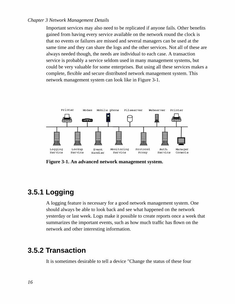
Important services may also need to be replicated if anyone fails. Other benefitsgained from having every service available on the network round the clock isthat no events or failures are missed and several managers can be used at thesame time and they can share the logs and the other services. Not all of these arealways needed though, the needs are individual to each case. A transactionservice is probably a service seldom used in many management systems, butcould be very valuable for some enterprises. But using all these services makes acomplete, flexible and secure distributed network management system. Thisnetwork management system can look like inFigure 3-1.
Figure 3-1. An advanced network management system.
3.5.1 LoggingA logging feature is necessary for a good network management system. Oneshould always be able to look back and see what happened on the networkyesterday or last week. Logs make it possible to create reports once a week thatsummarizes the important events, such as how much traffic has flown on thenetwork and other interesting information.
3.5.2 TransactionIt is sometimes desirable to tell a device "Change the status of these four
16

Chapter 3 Network Management Details
variables to this. If one can not be changed, none should be changed". This iswhat transaction means, either all or nothing. This service is probably seldomused, but can be very valuable on some occasions. Also to consider, if atransaction is being performed, another parallel request must not change any ofthe values (in the agent) that the transaction is about to either set or read. Let ussay a transaction includes "set value X to 1" and "set value Y to 2". If the Xvalue is set and a parallel action changes permissions so value Y can not be set,then we should not have set X either. An easy solution would be to save thevalue of X before trying to set Y and then set X to the old value if setting Y fails.But then, if another parallel request reads the value of X, then he got the number1 instead of the old value. Because of this reason, transactions have to lock thevalues it wants to set and read. A transaction can also involve several devices. Ifa value can not be set on one of the devices included in the transaction, none ofthe values on the other devices must be changed either.
3.5.3 Event HandlerAn event handler receives events on the network and makes appropriate actions.If the event handler were built-in into the manager, the network engineers wouldhave no idea what happened on the network while they were at home during thenight or the weekend, when the manager was not running. When the eventhandler receives an event it can either act intelligently and try to fix the problem(if it was a problem) without interaction from the network engineers or it couldsend information about the event to the log service or it could forward the eventto the network manager application or a combination of these. Today, mostproblems must be fixed by network engineers. With intelligent servers one cantry to find out what the problem is causing an event and fix it. This will probablybe more common in the future as AI research makes progress. An examplewhere a problem can be fixed without interaction from an engineer could be thefollowing scenario: A network scan finds a security hole in a service provided byone of the computers in a network. When the vulnerability is found, it uses anupdate utility to get the latest security upgrades for the software that had the bug.It then logs in to the computer and upgrades the software. After that an event issent to the event handler that tells it that the problem was fixed.
When an event handler gets a critical event it informs the manager. If the
17
Chapter 3 Network Management Details
manager does not acknowledge there is problem, the event handler can regularlyremind the manager about the critical event. This way an event is neverforgotten.
3.5.4 Lookup ServiceWhen a manager application boots it wants to know what devices there are onthe network. One possible solution is to make a broadcast ping and see whatanswers it gets. Probably the application also wants to know what services areprovided by the devices and asks every device individually. Another bettersolution is to have a lookup service that registers all the devices and theirservices and interfaces. When a manager wants to know what devices or servicesthere are on the network, it only needs to ask the lookup service.
3.5.5 Monitoring ServiceThis works like an RMON (seeSection 5.4for more information) but with someadded features. Instead of being a MIB (seeSection 5.1.5) it is an ordinaryprogram (non-GUI) running and inspecting traffic. It can send events to the eventhandler if there is suspicion of intrusion, performance problems or any otherkind of problem. Traffic is also stored in a database and the Monitoring Serviceis thus offering a Traffic Statistics Service at the same time.
3.5.6 Authentication ServiceMost often no one should be allowed to do anything on a device if notauthenticated. Most management protocols use authentication of some form, sowhy use an authentication service? An enterprise network can contain thousandsof devices or more and maintaining passwords on all these devices demands a lotof work. A solution to this is to have an authentication server, for exampleKerberos, that handles the authentication between users and devices. Then thenetwork manager only needs to authenticate to the authentication server and theserver will handle the rest of the authentications.
18

Chapter 3 Network Management Details
3.5.7 History ServiceFor configuration management, it is desirable to have a history of setups for alldevices. Whenever a network engineer changes the setup of a device, the newsetup should be recorded. This would provide functionality similar to CVS; itwould be possible to retrieve old setups, to trace what have been changed andwho has changed it etc. This is valuable when, for example, one has detectedperformance problems. One can check if the configuration was changed recentlyand restore an old configuration to see if that solves the performance problems.History should be stored on a central server, so any other service or client canget the history information anytime they want. The disadvantage with usinghistory is that all configuration traffic must go through a middleman. Allconfiguration traffic is first sent to the history service, which then forwards it tothe managed device. Alternatively, the client can duplicate its messages, sendingthem both to the History Service and to the device.
This way of storing configuration history has limitations though. If one manuallyconfigures a device or configures it with another network management client,history will not be saved. Only configurations done from network managementclients, following the design inChapter 9, are stored in history. A possible wayto go around this is to regularly poll the devices and see if anything has changed.This causes lots of traffic (polling every possible managed object on everydevice), too much to be recommended and designed for in this thesis.
3.5.8 ProxiesProxies can be useful in several ways. A proxy can be used to translate a
19

Chapter 3 Network Management Details
protocol to another protocol, seeFigure 3-2.
Figure 3-2. Proxy converting SNMP to CMIP.
Proxies can also be useful when the management protocol lacks security. Let ussay a manager on a network A wants to communicate with a device on networkB and the device only knows a protocol that does not use any encryption. Then aproxy can be used on network B that can receive encrypted traffic from themanager and forward unencrypted traffic to the device. This does not make thecommunication encrypted all the way to the device, but it protects fromeavesdropping on all networks between A and B.Figure 3-3shows how thisworks.
Figure 3-3. Proxy decrypting AES-encrypted SNMPv1 traffic.
20

Chapter 3 Network Management Details
3.6 Distribution ModelsCentralized management has been the most common distribution model. It is thesimplest and most intuitive model to use. However, the demand for bettermanagement systems are growing. They need to be flexible, robust, efficient andscalable. The bandwidth and number of network devices are constantlyincreasing, different networks and systems are working together, more and moreservices are offered to customers. Because of the demands getting higher, thecentralized model is not good enough for large or complex networks. Smallcompanies with for instance three printers, two routers and 30 computers mightstill make it with the centralized way though.
To decentralize the management,mid-level managersare used. The top-levelmanagers delegate tasks to the mid-level ones, which means less used bandwidthand distribution of computer power and storage. Robustness can be increasedwith redundancy and flexibility can be improved by dynamically adding andremoving services from the agents.
ISO enumerates four management distribution models:
• Centralized
• Weakly distributed
• Strongly distributed
• Cooperative
Centralized management consists of two levels, one single top-level managerand the agents (devices). If the managers (both top-level and mid-level) areapproximately as many as the agents, it is called cooperative management. Inbetween these two are weakly and strongly distributed management.Table 3-1describes how this classification is made in numbers,m being the number ofmanagers,n the total number of elements (top- and mid-level managers +agents).
21

Chapter 3 Network Management Details
1 = m centralized management1< m� n weakly distributed
management1� m< n strongly distributed
managementm≈ n cooperative management
Table 3-1. Classification of distribution models by numbers.
Figure 3-4illustrates the differences of the the models in another way, with a)centralized, b) weakly distributed, c) strongly distributed, d) cooperativemanagement.
Figure 3-4. Different distribution models.
Centralized and weakly distributed management systems typically use strictlyvertical delegation of tasks, that is the managers only delegate tasks to managers
22

Chapter 3 Network Management Details
a level below them. In strongly distributed and cooperative management themid-level managers also delegate tasks to each other on the same level, so thereis no clean hierarchy. Dynamic delegation of management tasks is possible withweakly distributed management, but is more convenient and efficient withstrongly distributed or cooperative management.
23

Chapter 3 Network Management Details
24
4 SecurityNetwork management exists because of the ability to connect computers andbuild networks. If a company connects its computers into a network we have aLAN. If the whole world connects its computers together we have the Internet.This provides amazing opportunities, but not without risk. When connecting acomputer to a LAN or the Internet you also make yourself open to several typesof attacks. To protect oneself from these attacks, one has to know what securityis and what security precautions can be taken.
In a network management system there are lots of information flowing.Depending on the system the information can be of little interest, but in manysystems there are information flowing that must not be exposed to any other thanthe network management administrators. Even if a network management systemresides in a LAN with a firewall to the Internet (belonging to a company orinstitute), security precautions must be taken. This is because many intrusionattempts are being done from the inside, by employees or by someone fromoutside being just temporarily on the inside.
A network management system does not have to be isolated to a LAN, onemight want to manage servers being located all around the globe. Securityprecautions should be taken in a LAN, but it is even more important and close tomandatory to have a good security solution if the network management systeminvolves servers outside the LAN. In a LAN there is a limited amount of peoplethat can and want to harm the company. On the Internet you open yourself to theunknown, having no idea who might want to hack the company’s servers.
Firewalls and Virtual Private Networks (VPNs) together provide a good securitysolution. They complement each other and solve many of the security issuescurrent in a network management system.
This chapter describes networking and security in detail. To really graspeverything you need to know networking and encryption basics. If there is anabbreviation you have no idea of what it means, there is a big change you find itin Cryptography and Network Security by Stallings [STA99].
25
Chapter 4 Security
4.1 What is Security?According to Gollman [GOL99] security mainly is defined by confidentiality,integrity and availability, while Mann [MAN00] thinks about security asconfidentiality, integrity and reliability and Black et al. [BLA00] asconfidentiality, authentication, integrity, access control and non-repudiation.There is no single definition of security, the definition used in this work is a mixof the mentioned ones:
• Confidentiality : prevention of unauthorized disclosure of information.
• Integrity : prevention of unauthorized modification of information.
• Availability : prevention of unauthorized withholding of information orresources.
• Authentication: prevention of faking ones identity.
• Non-repudiation: prevention of the ability to deny having been part of atransaction.
How these are addressed by a VPN is explained inSection 4.3.1.
4.1.1 ConfidentialityWhen information flows on the network it can be eavesdropped. If theinformation is not encrypted someone else can sniff the network and read the
26

Chapter 4 Security
information.
Figure 4-1. Eavesdropping by a third part.
If you just browse the web this might not be a problem, maybe you do not care ifsomeone knows that you have visited CNN’s web site to read the news. But ifyou are using your bank’s website and make transactions, you probably do notwant anyone else to be able to sniff your secret code to the bank account. Toprevent someone from getting the code, the code must be encrypted.
4.1.2 IntegrityEven for data that is not confidential, one must still take measures to ensure dataintegrity. For example, you may not care if anyone sees your monthly orderings,but you would certainly care if the numbers were modified. Data integrityensures that transactions are not modified.
4.1.3 AvailabilityIf an organization connects its LAN to the Internet, it will probably require theInternet to always be available. A LAN usually has a firewall as its only entrypoint. This is a critical point of failure and also when it comes to availability. Ifthe firewall is not functioning as it should, the users will not be able to reach theInternet. Denial of Service (DoS) is the most common attack to make a serviceunavailable. DoS can, for example, be when someone is sending numerous ofInternet packets to a certain host. The receiving computer will get so many
27

Chapter 4 Security
packets to process it can not manage them all and it will start to drop them. Itwill also drop packets coming from friendly users and the computer can notserve the users as it was meant to do. Even if the computer can manage all thesepackets, the connection might get saturated and it would not be possible to sendany other packets. If availability is very important to a LAN, then DoS can bedisastrous. But DoS attacks of this kind are mostly harmless and only affects theavailability during the attack. Afterwards most gets back to normal. But DoS canalso include filling disk space and abuse of other resources. Authentication is thebest method to prevent abuse of resources as only authorized users should beable to use them. Having secondary services (redundant services on other serversoffering the exact same functionality and having the same data) and building adistributed system is a good way to preserve availability. Then if a service failsfor some reason, another can take over without any loss of functionality.
4.1.4 AuthenticationSecurity precautions like encryption and integrity checks, making no one able toread or modify the information, will not help if the parties can fake theiridentities and pretend they are trusted users. Authentication is the process ofverifying that someone is who she claims to be. Authentication is very importantand can be performed in several ways:
• User authentication
• Host authentication
• Key authentication
User authentication is the most used authentication method and typicallyinvolves username and password. You use it, for example, when logging in to aUNIX or Windows NT workstation. Because username and password givesaccess to a service, they should be encrypted.
Host authentication is done without interaction from the user. It allows ordisallows certain hosts to use a service. The service checks the source address inthe IP header of the network packet (in an IP based network) and compares it
28

Chapter 4 Security
with the entries in a database. If the address is listed as "not allowed", then theservice can not be used and the user authentication process never needs to takeplace. Host authentication is often used in combination with user authentication.The source address can be faked so even if it is known that a certain user uses acertain IP address, user authentication should be used too. Host authentication isbetter used for disallowing hosts rather than allowing.
Another way to authenticate is key authentication. A key authentication systemprovides both host authentication and user authentication with the addedadvantage of not having to rely completely on the destination host, although herea key server is used and it is a critical service and it has to be relied on instead.More about key authentication can be found in various books, for example[STA99].
4.1.5 Non-repudiationWith the above mentioned security precautions, one can safely log in to a bank’swebsite and make transactions. Confidentiality prevents disclosure of the code tothe bank account. Integrity guarantees that the transaction really will be theamount you wanted. No one can change the amount unnoticed. Availabilitymeasures assure you that the website is always available. Authenticationprevents anyone except the owner from using the bank account. But still there isa weakness in this transaction, from the bank’s point of view. The bank accountowner must not be able to withdraw a certain amount of cash and then be able todeny the transaction. The owner must sign the transaction, leaving no way todeny it. Digital Signatures is the electronic world’s replacement for pen-basedsignatures. More information about digital signatures can, for example, be foundin [STA99].
4.2 FirewallsA firewall is a system (often a router or PC) that protects trusted networks fromuntrusted networks. The trusted networks could, for example, be LANs of anorganization and the untrusted network could be the Internet. A firewall is
29

Chapter 4 Security
typically used by a company to protect its local area network from abuse by userson the Internet. Bellovin et al. [BEL94] lists the following goals for a firewall:
1. All traffic from the inside (the LAN) to the outside (the Internet), and viceversa, must pass through the firewall. This is achieved by physicallyblocking all access to the local area network except via the firewall.
2. Only authorized traffic, as defined by the local security policy, will beallowed to pass.
3. The firewall itself is immune to penetration. This implies the use of a trustedsystem with a secure operating system.
A firewall defines a single choke point that keeps unauthorized users out of theprotected network and prevents potentially vulnerable services from being usedfrom the outside. A firewall is a must for a LAN to become secure, but it can notmake it secure alone. It needs help from, for example, virtual private networks.
There are different types of firewalls and as with the definition of security, thereis no single worldwide definition of what a firewall is. According to Stalling[STA99] there are three types of firewalls:
• Packet-filtering firewall
• Circuit-level gateway
• Application-level gateway
A firewall does not necessarily belong to just one of the categories, a firewall canhave functionality combining two or three of them.
4.2.1 Packet-filtering FirewallThe packet-filtering firewall is the most common firewall. It can be seen as atraffic cop. The firewall administrator chooses what machines an outsider cansee (on the inside) and the services on those machines with which she cancommunicate. She also chooses what machines on the Internet an internal usercan see and what services that can be used. This is done by allowing ordisallowing certain traffic to pass from one side to the other. This filtering of
30

Chapter 4 Security
traffic can be applied at IP and TCP/UDP level, that is the filtering can be basedon source IP, destination IP, source port, destination port and protocol. A firewallcan thus, for example, allow FTP (port 21) passing through, while blockingTelnet (port 23).
As the firewall is the only entry point to the local area network, all traffic to theInternet or to the LAN can be monitored and logged. When certain patterns intraffic are discovered alarms can be triggered. This is essentially what a packetfiltering firewall is about. It can not prevent abuse from users inside the LAN andit can not perform miracles. If a malicious host fakes its IP address, disallowingcertain source IP addresses will not guarantee that the incoming IP packetsbelong to friendly hosts.
4.2.2 Circuit-level GatewayWhen host A, which is outside the firewall, wants to communicate with host B,which is inside the firewall, a circuit-level gateway first checks whether to allowthe communication or not. If the communication is trusted, then the firewall setsup two TCP connections, one between host A and the gateway and one betweenthe gateway and host B. Once the two connections are established, the firewalltypically relays TCP segments from one connection to the other withoutexamining the contents.
A circuit-level gateway provides another security function, it is aproxy server. Aproxy server is a firewall that uses a process called address translation to map theincoming IP addresses to a "safe" IP address. This address is associated with thefirewall from which all outgoing packets originate. Because of this, acircuit-level gateway is often used by users wanting to be anonymous on theInternet - the users will be masqueraded as the proxy server. An example of acircuit-level gateway implementation is the SOCKS package, version 5. It isdefined in RFC 1928.
4.2.3 Application-level GatewayLike a circuit-level gateway, an application-level gateway (also called a proxyserver) intercepts incoming and outgoing packets, runs proxies that copy and
31
Chapter 4 Security
forward information across the gateway, and functions as a proxy server,preventing any direct connection between a trusted server or client and anuntrusted host. However, the proxies that an application-level gateway runsdiffer in two ways from the proxies that a circuit-level gateway uses:
• The proxies are application specific.
• The proxies can filter packets at the application layer of the TCP/IP model.
Application-specific proxies accept only packets generated by services they aredesigned to copy, forward and filter. For example, only a Telnet proxy can copy,forward and filter Telnet traffic. If a network relies only on an application-levelgateway, incoming and outgoing packets cannot access services for which thereis no proxy. For example, if an application-level gateway ran FTP and Telnetproxies, only packets generated by these services could pass through the firewall.All other services would be blocked.
Application-level gateways can also restrict specific actions from beingperformed. For example, the gateway could be configured to prevent users fromperforming the FTPput command. This command lets users to copy files to theFTP server. Prohibiting this action can prevent serious damage of theinformation stored on the server.
A disadvantage of application-level and circuit-level gateways compared topacket-filtering firewalls, is the additional processing overhead, which is theresult of having two connections for each peer-to-peer communication. Anadvantage with the application-level gateway is that it is more secure than purepacket-filtering firewalls. If there is no Telnet proxy, no Telnet traffic can berouted, you do not have to add any filtering rules specifying this. In addition, it iseasy to log and audit all incoming traffic. This makes it possible to, for instance,block e-mails that are infected with a certain virus.
Example of a firewall protecting a LAN is shown inFigure 4-2.
32

Chapter 4 Security
Figure 4-2. Firewall protecting a network.
4.3 Virtual Private NetworkA virtual private network is a way to simulate a private network over a publicnetwork, such as the Internet. This private network can consist of any computersconnected to the Internet or it can just simply connect computers in a LAN.VPNs make these private networks secure, through encryption, authentication,packet tunneling and firewalls.Figure 4-3illustrates a VPN consisting of adial-up client and a LAN. All communication between the dial-up client and theLAN is encrypted and authenticated. With VPN technology one can build virtualprivate networks of any computers on the Internet and the communication willbe secure. One can also use VPN isolated inside a LAN. It can be useful for a
33

Chapter 4 Security
network management system.
Figure 4-3. Example of a Virtual Private Network.
According to Virtual Private Network Consortium [VPNC] there are three majorprotocols for VPN. They are:
• IPSec
• L2TP
• PPTP
[VPNC] also thinks IPSec will be the dominating protocol in the near future. Asit is a very good idea to use IPSec in a network management system, it is brieflyexplained in the next section. It is out of the scope for this thesis to investigatehow secure IPSec is, but it is discussed briefly so you know what it is and how itworks.
4.3.1 IPSecIP packets have no inherent security. It is relatively easy to forge the addresses ofIP packets, modify the contents, replay old packets and inspect the contents.Therefore, there is no guarantee that IP packets received are from the claimedsender, contain the original data that the sender placed in them, nor that they notwere inspected by a third party. IPSec is a framework of open standardsaddressing these security issues, that is it ensures private communications overIP networks. Based on standards developed by the Internet Engineering Task
34

Chapter 4 Security
Force (IETF), IPSec ensures confidentiality, integrity and authenticity of datacommunications across IP networks and provides replay protection andnon-repudiation. IPSec is integrated into the TCP/IP-stack and providesencryption at the network layer - a figure of the TCP/IP-stack can be found inglossary undernetwork reference modelsin Glossary. The encrypted packetslook like ordinary IP packets and can easily be routed through any IP network,without any changes to the intermediate equipment. The only devices that knowabout the encryption are the end points. Official information about the IPSecarchitecture can be found in RFC 2401.
4.3.1.1 IPSec Modes
IPSec is operating in the network layer. It takes the original IP packet, processesit and makes a new one. IPSec supports two modes of operation,transportandtunnel.
Transport Mode
In this mode IPSec operates in the end points and encryption will thereforeprotect the packets all the way between the two parties.
Figure 4-4. IPSec in transport mode.
The two communicating parties’ computers must have IPSec integrated intotheir TCP/IP-stacks. IP packets are divided into a header and a data part. Intransport mode, only the IP data is encrypted, the original IP header is left intact.This mode only adds a few bytes to each packet. It also allows devices on the
35

Chapter 4 Security
network to see the final source and destination of the packet and an attacker canperform some traffic analysis.Figure 4-5shows how an IP packet is processed intransport mode.
Figure 4-5. IPSec tunneling in transport mode.
Transport mode does not work very well with firewalls. As both TCP andapplication data is encrypted through the firewall, there is no way for the firewallto use any kind of filters other than at IP level, that is the source and destinationIPs. A Packet-filtering firewall and a circuit-level gateway would loose much oftheir functionality and an application-level firewall would not work at all.
Tunnel Mode
In tunnel mode the entire original IP packet is encrypted and put in a new IPpacket. This is calledtunneling. This allows routers to act as IPSec proxies andthe end points do not have to have IPSec integrated into their computers. See
36

Chapter 4 Security
Figure 4-6.
Figure 4-6. IPSec in tunnel mode.
For example, let us say that users A and B wants to communicate with eachother and that they are on two separate LANs separated by the Internet. When Asends information to B the information will leave A unmodified andunencrypted. When it reaches the LAN’s router/firewall (which knows IPSec),the firewall encrypts the packets (even the IP header) and adds a new IP headerwhich tells the tunnel end points (router A and B). It then sends the modifiedpackets to the router/firewall on the LAN where B resides. The router/firewallwill decrypt the data and the original IP packets that A sent will be sent to userB. The advantages with this is that:
1. The only computers that must have IPSec installed are the routers/firewalls.
2. Traffic analysis can not be performed, the packets on the Internet will onlysay router A and B in the header, it does not unveil the IP addresses of theend points, that information is encrypted.
The disadvantage is that the security is not used end to end, information flowsunencrypted on both LANs.Figure 4-7shows how the IP packets get processedby the firewall.
37

Chapter 4 Security
Figure 4-7. IPSec tunneling in tunnel mode.
Tunnel mode works perfectly with firewalls. In tunnel mode, the firewall willdecrypt the traffic and it can therefore also analyze the packets and make full useof its features. All three firewall types can be used in this mode.
4.3.1.2 IPSec in Details
The standards define Authentication Header (AH, RFC 2402) to provide dataintegrity and authenticity of data and Encapsulating Security Payload (ESP, RFC2406) to provide confidentiality, data integrity and authenticity of data. Keymanagement and security associations (SA, RFC 2408) are handled by InternetKey Exchange (IKE, RFC 2409). Depending on what security measures onewant to take, one can use the appropriate combination of these functions.
Authentication Header
AH ensures integrity and authenticity of data. It also provides an optional replayprotection. If replay protection is used, it is established by the receiver when asecurity association is established. AH uses a keyed hash function to make asignature of the data. Digital signature technology is not used, according toCisco [IPSEC] it is too slow.
Encapsulating Security Payload
IPSec handles encryption at IP level using ESP to protect the confidentiality,integrity and authenticity of of the IP packets. ESP can also provide replayprotection. ESP was designed to support almost any encryption algorithm, DES
38
Chapter 4 Security
being the most common one. ESP supports some authentication, partiallyoverlapping with AH.
The IP header includes information of what protocol (e.g. TCP, UDP) the packetincludes. Instead of TCP or UDP it can also be ESP. Because ESP is just anotherprotocol, ESP can be transported on any IP network.
Security Association
IPSec provides many options for performing network encryption andauthentication. The two communicating parties must determine exactly whichalgorithms to use (for example DES for encryption and SHA for integrity). Afterdeciding algorithms the two parties must share session keys. All these securityparameters make a Security Association. IPSec does not itself have a mechanismfor creating such an association, it relies on IKE to do this work.
Internet Key Exchange
IKE creates an authenticated, secure tunnel between two parties and thennegotiates the Security Association for IPSec. IKE is generic enough to be usedto define SAs other than those for IPSec. To encrypt the tunnel both parties haveto share a common session key, Diffie-Hellman is used for this. IKE supportsseveral methods for authentication. The two parties have to agree on one of them.The methods generally implemented into IPSec is, according to Cisco [IPSEC]:
• Pre-shared keys: The same key is pre-installed on each host. IKE hostsauthenticate each other by computing and sending a keyed hash of data. If thereceiving host is able to create the same hash using its pre-installed key, itknows that both parties mush share the same secret, thus authenticating theother party.
• Public key cryptography: Each party generates a pseudo random numberand encrypts it with the other party’s public key. The ability for each party tocompute a keyed hash containing the other party’s number, decrypted with thelocal private key, authenticates the parties to each other. With this system oneparty can deny it took part in the exchange. RSA is the public key algorithmthat is typically used.
39

Chapter 4 Security
• Digital signature: Each party digitally signs data and sends it to the otherparty. This method is similar to public key cryptography, but this method alsoprovides non-repudiation. Non-repudiation means that one party can not denyit took part in the key exchange.
4.3.1.3 IPSec Security Algorithms
IPSec does not define the specific security algorithms to use, but provides anopen framework for implementing standard algorithms. Implementations ofIPSec will use:
• Diffie-Hellman for exchanging keys between hosts on the network.
• public key cryptography for signing the Diffie-Hellman exchanges toguarantee the identity of the two parties and avoid man-in-the-middle attacks.
• bulk encryption algorithms for encrypting data. DES is the most commonalgorithm, but there is also IDEA, Blowfish and RC5.
• keyed hash algorithms, such as HMAC, combined with traditional hashalgorithms such as MD5 or SHA.
• digital certificates signed by a certificate authority to act as digital ID cards.
DES is the most common encryption algorithm, but it is not the most secure one.DES uses a key to encrypt the traffic. The key can be found by trying everypossible key until it succeeds to decrypt the data. When it is found it can be usedto decrypt all the traffic been encrypted with this key. On average, half of allpossible keys must be tried to achieve success. How long it takes on average tosearch the key is dependent on the length of the key. DES is using a relativelyshort key, 56 bits.Table 4-1is taken from [STA99], it shows average time to doexhaustive key search.
40

Chapter 4 Security
Key size Number ofalternative keys
Time requiredat 1encryption/ µs
Time requiredat 106
encryptions/ µs32 232 = 4.3 × 10⁹ 231 µs = 36
minutes2 milliseconds
56 256 = 7.2 × 10¹⁶ 255 µs = 1142years
10 hours
128 2128 = 3.4 × 1038 2127µs = 5.4 × 1024
years5.4 × 1018 years
Table 4-1. Average time required for exhaustive key search.
For each key size, the results are shown assuming it takes 1µs to perform asingle encryption. This is, according to Stallings [STA99], a reasonable speedfor today’s computers. For a 56-bit DES encrypted message, it would take 1142years to break it with a single computer. By distributing power the time can dropseverely. Last column in the table shows that DES is not very safe. One mightnot have 106 computers available, but the table at least shows that the time forexhaustive search can be dropped to times that can not be considered safe. DESwas once cracked in 22 hours and 15 minutes by Distributed.net [DNET]. If3DES (168 bits) and AES (128, 192 or 256 bits) are implemented in the IPSecsoftware, they should be used instead of DES. Information about AES can befound on the AES official homepage [AES].
4.4 A Secured Network ManagementSystem
The idea behind a firewall/VPN combination is to use the firewall to keepunwanted visitors from entering the network, while allowing VPN users through.This is done by first disallowing all traffic through the firewall. Then specificports are opened in the firewall allowing the encrypted VPN traffic to pass by. IfVPN is used right and the firewall is secured, then users will have a hard time ifthey try to attack the network.
41
Chapter 4 Security
In a network management system it would be recommended to use transportmode. This makes the data flow secure all the way to the end points. But thisalso makes one having to install IPSec on every host where a networkmanagement services or clients reside. Hopefully operating systems will start toship with IPSec when it becomes widespread. Solaris 8 ships with its own IPSecimplementation. It is working, but it is not complete yet. See Solaris ProductLine [SOL] for more information.
The network management system this thesis proposes uses IPSec for security. Toget confidentiality one could instead use SSL, for authentication one could useKerberos. What makes IPSec the recommended solution is because:
• IPSec provides a complete security solution in one package. One does nothave to depend on several security solutions and try to get them to work witheach other.
• Many other encryption software works at application level (e.g. SSL) andevery application must be modified to add the security. IPSec works on IPlevel and encrypts the traffic transparently from the application’s point ofview, no security have to be added to the application. This eases the designand implementation of the network management system.
42

Chapter 4 Security
Figure 4-8. A network management system secured by a firewall and VPN.
43

Chapter 4 Security
44

5 Network Management ProtocolsVPN solves encryption and the other security precautions between the services.Most devices being managed today are dumb and do not know how to use IPSecor SSL. The communication from and to the devices will not be encrypted,unless the management protocol itself provides it. Therefore, the securityimplemented in the protocols are still important and they are described for eachprotocol mentioned in this chapter.
5.1 SNMPv1The Simple Network Management Protocol (SNMP, RFC 1157) was introduced1990 and has since then been the management protocol that has dominated thenetwork management market. It allows for management data to be collectedremotely from devices and applications and for devices to be configuredremotely. Most network devices today have SNMP MIBs and agents that knowthe SNMPv1 protocol.
SNMPv1 uses UDP (RFC 768)for exchanging messages between manager andagent. UDP is connectionless and uses a minimum amount of resources, but isunreliable. An SNMP agent listens on UDP port 161 for SNMP messages. Whenit receives one it checks the password (called a community name). If thepassword is correct, the agent will try to process the request. Description of arequest follows in next section.
5.1.1 SNMP requestSNMPv1 provides four operations - two to retrieve data, one to set data and onefor a device to send a notification:
• get, which is used to retrieve specific objects.
• get-next, which is used to retrieve objects by traversing the MIB tree.
• set, which is used to modify objects.
45
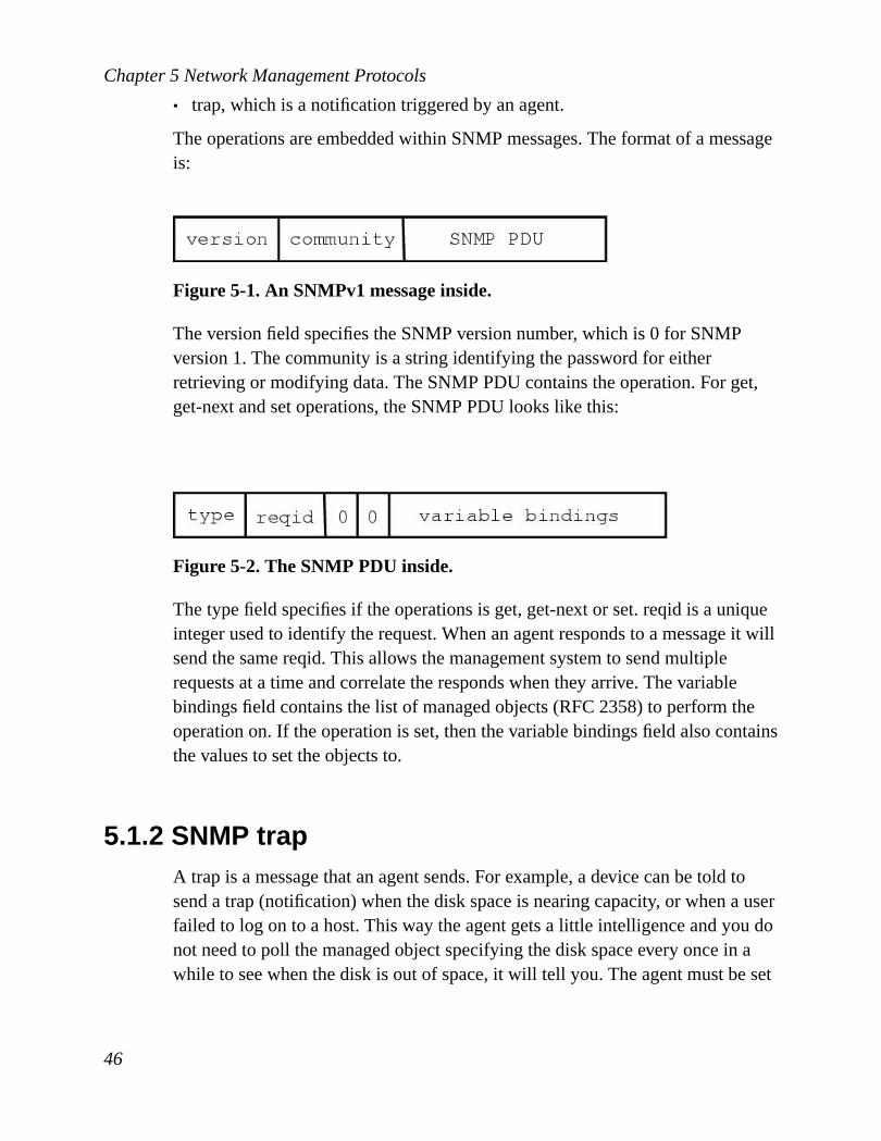
Chapter 5 Network Management Protocols
• trap, which is a notification triggered by an agent.
The operations are embedded within SNMP messages. The format of a messageis:
Figure 5-1. An SNMPv1 message inside.
The version field specifies the SNMP version number, which is 0 for SNMPversion 1. The community is a string identifying the password for eitherretrieving or modifying data. The SNMP PDU contains the operation. For get,get-next and set operations, the SNMP PDU looks like this:
Figure 5-2. The SNMP PDU inside.
The type field specifies if the operations is get, get-next or set. reqid is a uniqueinteger used to identify the request. When an agent responds to a message it willsend the same reqid. This allows the management system to send multiplerequests at a time and correlate the responds when they arrive. The variablebindings field contains the list of managed objects (RFC 2358) to perform theoperation on. If the operation is set, then the variable bindings field also containsthe values to set the objects to.
5.1.2 SNMP trapA trap is a message that an agent sends. For example, a device can be told tosend a trap (notification) when the disk space is nearing capacity, or when a userfailed to log on to a host. This way the agent gets a little intelligence and you donot need to poll the managed object specifying the disk space every once in awhile to see when the disk is out of space, it will tell you. The agent must be set
46

Chapter 5 Network Management Protocols
up with the address of the station so it knows where to send the SNMP trapmessage.
5.1.3 AuthenticationThe only authentication supported is the community name. Mostly there are twocommunities defined by an agent, one for all the managed objects that can beread, the other for objects that can be modified. A community can be anycollection of managed objects within a device’s MIB with an access mode ofread-only or read-write applied to the whole community. There can be morecommunities, how many is up to the implementation. This community name orpassword is not encrypted so eavesdropping will quickly reveal it.
5.1.4 SMIStructure of Management Information (SMI, RFC 1155) is a set of rules forspecifying the management information that a device maintains. Every datavalue that can be remotely collected from a device are managed objects. SMIrules are used both to name and define these managed objects. All the objects arearranged in a tree structure. An object’s location in the tree identifies how to
47

Chapter 5 Network Management Protocols
access the object.Figure 5-3shows the top of the tree.
Figure 5-3. The SNMP PDU inside.
The sysUpTime object is identified as 1.3.6.1.2.1.1.3. Most often you find themanaged objects in the 1.3.6.1.2-branch. This identification is called anOBJECT IDENTIFIER and is used to access objects within a MIB. Only leavescan be accessed, the mgmt node can not be accessed.
5.1.5 MIBThe Management Information Base (MIB, RFC 1156) is a definition of theinformation accessible on a device through a network management protocol. Theinformation consists of managed objects and every managed object has a valuewhich can be read or set. If a device supports MIB, one knows what informationcan be collected from it. Devices can have properties that are not included in
48

Chapter 5 Network Management Protocols
MIB and therefore vendor-specific MIBs exist. They are mostly extendedversions of MIB, so MIB data can be collected and also vendor-specific data.
MIB is a virtual information store. The MIB does not store information, it justtells what data can be collected. When a manager asks an agent for some data,the agent uses the device’s software or hardware to get the data. Thisinformation is not stored in a central database.
5.1.6 SNMPv1 todayEstimating the usage of a protocol is not very easy, but when most books andweb pages say "SNMPv1 is the most widespread network managementprotocol", one probably should believe it. In a few years, SNMPv1 probably willleave the crown to SNMPv3, but of course it is only speculations.
5.2 SNMPv2The lack of many good features in SNMPv1 resulted in a work on SNMPv2(RFC 1441). The new version was, however, no big success. There weresignificant efforts on the security, but the lack of consensus resulted in securitybeing dropped from the final specification. For SNMPv2, security is still basedon community names and the system architecture is essentially the same as forversion 1. Further, version 2 is not backward compatible with version 1.
SNMPv2 defines a new operation,get-bulk. Its purpose is to retrieve portions ofa table. This is similar to walking through a table with repeatedget-nextcommands. SNMPv2 also introducesInformmessages, which is similar to traps.The problem with traps though, is that they are unreliable (UDP is unreliable).Inform can be seen as an SNMPv2 trap that can be retransmitted if it does notget acknowledged.
SNMPv2 added new capabilities to the SNMP protocol. In January 1996, RFC1902 updated SMI to be used with SNMPv2, SMIv2. Another MIB was alsoadded, it was named MIB-II (RFC 1213) and is located in the 1.3.6.1.2.1-branch.
49

Chapter 5 Network Management Protocols
5.2.1 SNMPv2 todaySNMPv2 (RFC 1441) is a step between SNMPv1 and SNMPv3. If it is widelyspread is hard to tell. Stalling [STA99] says all three versions of SNMPv3 are inactive use. Various websites mean that SNMPv1 still is de facto standard andthat SNMPv2 is ignored waiting for SNMPv3. Because of the relatively smallchanges from SNMPv1 and the uncertainty of the usage, SNMPv2 is notdescribed in further detail.
5.3 SNMPv3SNMPv3 (RFC 2570) addressed two major areas, administration and security.Another major goal was to have a modular architecture. For instance if newsecurity protocols are developed, they are now easy to add without having torelease a new version of the protocol. What was called managers and agents inSNMPv1 are now called entities.
5.3.1 Architecture OverviewAn SNMP entity contains two parts, an engine and applications.Figure 5-4
50

Chapter 5 Network Management Protocols
shows an entity and its modular structure.
Figure 5-4. SNMPv3 entity architecture.
5.3.1.1 Entities
As you can see from the figure, the engine is made of the following modules:
• Dispatcher
• Message Processing Subsystem
• Security Subsystem
• Access Control Subsystem
The dispatcher handles sending and receiving messages. When it receives amessage it determines what version of SNMP it belongs to and sends themessage to the appropriate Message Processing Subsystem. The MessageProcessing Subsystem is itself divided into three modules as you can see inFigure 5-5. New modules are easily added if wanted.
51

Chapter 5 Network Management Protocols
Figure 5-5. SNMPv3 subsystem architecture.
If the dispatcher determines the version to 3, then the message is sent forward tothe SNMPv3 Message Processing Model. The dispatcher is also responsible forsending the final PDU to the applications. Messages look different among thedifferent versions of SNMP and therefore the data are being extracted differentlyfrom the messages. The SNMPv3 Message Processing Model handles themessages it knows about and therefore it extracts only the SNMPv3 messages.When extracted, the data portion of the message is sent to the SecuritySubsystem for decryption and authentication. The Security Subsystem alsohandles encrypting of data. The module structure of the Security Subsystemlooks like inFigure 5-6.
Figure 5-6. SNMPv3 security subsystem architecture.
As SNMPv3 is backward compatible with SNMPv1 and v2 it has both a User-based Security Model (USM, RFC 2574) for processing SNMPv3 messages anda Community-based Security Model for processing SNMPv1 and v2 messages.The module structure makes it easy to add another security module if wanted.When the data is extracted the PDU is sent to the appropriate application. Thenwe have the Access Control Subsystem. It is responsible for determining if amanaged object can be accessed. There is currently only one access controlmodel, but others can be defined in the future. SeeFigure 5-7for the structure ofthe Access Control System.
52
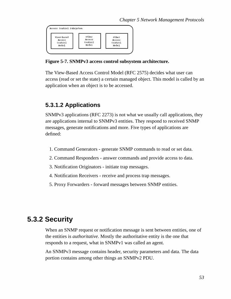
Chapter 5 Network Management Protocols
Figure 5-7. SNMPv3 access control subsystem architecture.
The View-Based Access Control Model (RFC 2575) decides what user canaccess (read or set the state) a certain managed object. This model is called by anapplication when an object is to be accessed.
5.3.1.2 Applications
SNMPv3 applications (RFC 2273) is not what we usually call applications, theyare applications internal to SNMPv3 entities. They respond to received SNMPmessages, generate notifications and more. Five types of applications aredefined:
1. Command Generators - generate SNMP commands to read or set data.
2. Command Responders - answer commands and provide access to data.
3. Notification Originators - initiate trap messages.
4. Notification Receivers - receive and process trap messages.
5. Proxy Forwarders - forward messages between SNMP entities.
5.3.2 SecurityWhen an SNMP request or notification message is sent between entities, one ofthe entities isauthoritative. Mostly the authoritative entity is the one thatresponds to a request, what in SNMPv1 was called an agent.
An SNMPv3 message contains header, security parameters and data. The dataportion contains among other things an SNMPv2 PDU.
53

Chapter 5 Network Management Protocols
Figure 5-8. SNMPv3 message format.
What is interesting in a security point of view in the header are msgFlags andmsgSecurityModel.
• msgID (message identifier) is an integer value uniquely identifying everymessage. This is used for matching requests with responds. It can also be usedas a delay protection, which is discussed inSection 5.3.2.5.
• msgFlags (message flags) is a 1-byte value that contains three flags (1 biteach): reportableFlag, authFlag and privFlag. reportableFlag determineswhether the message can cause a report to be generated. authFlag indicates ifauthentication is used for the message. If it is set one of the two SecurityModels will be used. If it is not set no authentication is needed. privFlagindicates whether encryption is used. If the flag is set, then one of the possibleencryption algorithms are used.
• msgSecurityModel (message security model) is an integer value that showswhat Security Model that should be used for the message. The sender andresponder must use the same Security Model when processing it.
The security parameters are specific to the security model being used. For theuser-based security model there are six parameters.
• msgAuthoritativeEngineID is the ID of the engine of the authoritative entity.This is among other things used for producing the encryption key.
• msgAuthoritativeEngineBootstells how many times the entity has rebooted.This is just together with msgAuthoritativeEngineTime to protect againstmaliciously delayed message.
54

Chapter 5 Network Management Protocols
• msgAuthoritativeEngineTime is the number of seconds since the engine lastrebooted.
• msgUserNameis a username which tells who you are. This is the same kindof username that is used when you log on to multi-user systems likeGNU/Linux, Solaris or Windows NT/2000.
• msgAuthenticationParametersis a string representing a MAC. If acalculated MAC matches with the MAC specified by this parameter, then themessage is authenticated.
• msgPrivacyParameterscontains an 8-byte string that represents a "salt"value which is used by encryption algorithms.
5.3.2.1 Authentication
When the User-based Security Model is used, authentication allows an entity toverify from whom the message is and to check if it is altered. Authenticationalso involves checking timestamps, which is a protection against delayed andreplayed messages. More about the timestamp protection is further discussed inSection 5.3.2.5. The non-authoritative entity uses a secret key to create afingerprint of the message it wants to send and then the authoritative entity alsocalculates a fingerprint (with the same authentication key). If they match, themessage is authenticated. HMAC-SHA-96 and HMAC-MD5-96 algorithms areused to make the fingerprints.
5.3.2.2 Confidentiality
Only the data portion (not header or security parameters) of the message can beencrypted. The encryption algorithm mostly used is CBC-DES. Discussion ofAES for SNMPv3 is in Internet Draft [AESID]. Because of the modularstructure, another algorithm that offers stronger encryption can be added. DES isno longer considered very secure. The time to do exhaustive search decreaseswith faster computers and with the technology of distributing computer powerand 56-bit keys are too small today.
55
Chapter 5 Network Management Protocols
5.3.2.3 Integrity
Authentication uses a secret key to produce a message authentication code(MAC) for the message. This MAC is included in the request message and theauthoritative entity produces its own MAC from the message and compares it tothe MAC included in the message. If they do not match, message got corruptedor someone has altered the message and it is discarded.
5.3.2.4 Availability
SNMPv3 has no defense against DoS attacks. One possible attack is forgingreports without authentication. This can make the receiving SNMP engine takeinappropriate actions. If for instance a report saying that an intrusion was madein a firewall, then the SNMP engine could possible be programmed to take thisfirewall down. This and other scenarios can cause big problems.
5.3.2.5 Capture, Replay and Delay
For a message to be authenticated it must be received within a certain timespace. It should not be possible for someone to capture an SNMPv3 message,hold it for two days and then send it. This is handled with the help of msgID,msgAuthoritativeEngineBoots and authoritativeEngineTime. It is thenon-authoritative engine’s duty to learn the engineBoots and engineTime of theauthoritative engine. When it learned theses value it will need to keep trackthose. Future messages will contain the non-authoritative engine’s idea of whatthe values are. When a message is sent to the authoritative engine the values arechecked if they match its own values. If the values are within a time window of150 seconds, then it is valid. The non-authoritative engine’s idea of engineBootsmust be exactly the same as the authoritativeEngineBoots value, otherwise it isnon-valid and discarded.
Non-authoritative engines also checks the time window when receivingmessages. If the non-authoritative engine’s idea of engineBoots is greater thanmsgAuthoritativeEngineBoots or if those are equal but engineTime differs morethan 150 from authorativeEngineTime, then the message is considered non-validand is discarded.
56

Chapter 5 Network Management Protocols
These precautions prevent messages from being replayed after more than 150seconds, but there is still the possibility that they are replayed within the 150seconds interval. This is prevented using msgID, which is found in the header ofthe message. msgID is unique for every message and when the non-authoritativesends a request it puts the msgID of the message in the cache. When it gets areply with a matching msgID it removes that msgID from the cache. So if themessage is replayed, the cache contains no entry with such a msgID and it isconsidered non-valid and is discarded.
Without authentication, someone could capture a message and change the valuesof msgID, engineTime and engineBoots and send it. Therefore these checks arenot performed when authentication is not used.
5.3.2.6 Key management
Secret keys are used for both authentication and privacy and both thenon-authoritative and authoritative entities share the same keys. Each entitysending a request has a username and a password that it they use forauthentication and privacy. The password is converted (by two differentalgorithms) to two keys, which is are used for authentication and privacyrespectively.
There might be many devices in the network and the user probably does notwant different passwords for every device, but you still do not want the wholenetwork compromised if an intruder got the hold of only one key. This isprevented by each authoritative entity having different keys for the same user. Byusing the snmpEngineID of the authoritative entity, a key can be generated thatis unique for a certain user and a certain authoritative entity.
The encryption algorithm used is CBC-DES. The CBC-DES keys are created ina similar way as the authentication keys were made.
It is a good policy to change the password every now and then. SNMP allowskeys to be set remotely. First a new password is chosen. Then a new key iscreated and a delta is calculated by using the old and the new password. Also arandom value is generated. The delta and random values are transferred to theauthoritative entity, which by the delta and random value can calculate the newkey. These two values can be sent without encryption, because the new key cannot be calculated from those values if the old key is not known. To me it looks
57

Chapter 5 Network Management Protocols
like this is not a good protection. You can continue trying to crack an old key. Ifyou after a long time success and discovers the password of a user, you cancreate every single key that has been used until today. This makes anon-authorized person able to be authenticated as that user, without having toknow the password.
5.3.3 PerformanceSNMPv3 needs more bandwidth than SNMPv1 because of the encryption.SNMPv3 is not used as much as SNMPv1 yet and it is hard to tell exactly howmuch larger the traffic is with SNMPv3 instead of SNMPv1. The encryption ofthe message needs more computer power, so network traffic is not the only issue.But computers have much power today, so if not the traffic is very heavy acomputer will not have any problems with the encryption. Network traffic ismore critical.
As have been explained inSection 5.4, very much bandwidth can be saved ifpolling is made close to the managed network devices. This is valid for SNMPv3or for any other network management protocol. Especially when encryption isused, much bandwidth can be saved. For some information it is just enough tomonitor the traffic flowing on the network.
5.3.4 LimitationsSNMP in general can only do what the MIB says it can do and the MIB is static.Only values from the MIB can be monitored. The flexibility is therefore not verygood (not talking about its modular structure). If you find out a new way todiscover intruders, you can not add a process that does this. Another limitationare the traps. Traps are not available for all the managed objects, only for some.Data monitoring is somewhat possible with RMON (seeSection 5.4), but if youwant more advanced monitoring, this is not possible with SNMP.
58

Chapter 5 Network Management Protocols
5.3.5 ConfigurationSNMPv3 uses an access control model named View-Based Control Model. Withthe use of this different users can get different accesses to different managedobjects.
5.3.6 SNMPv3 todayVarious web pages say "SNMPv3 is not as wide-spread as SNMPv1". However,Cisco Systems has full SNMPv3 support in their operating system IOS version12.0(3)T. Based on the fact that SNMPv1 lacks several important features andthat a large company like Cisco Systems now supports SNMPv3, one wouldguess that SNMPv3 will be the new de facto standard some time in the future,but exactly when this happens no one knows. As SNMPv3 is backwardcompatible with SNMPv1, a company does not have to be afraid it will loseearlier customers because they ship SNMPv3 with their hardware.
5.4 RMONRemote Network Monitoring (RMON, RFC 1757) is an addition to the SNMPstandards (SMI, MIB, SNMP). It defines a remote monitoring MIB thatsupplements MIB-II and provides the network engineers with lots of usefulinformation that MIB-II does not provide. The information in the RMON MIBcan be accessed using the ordinary SNMP operations. An SNMP-enabled devicecan, with MIB-II, learn about the traffic in and out of the device, but can notlearn about the traffic on the LAN as a whole. An RMON agent monitors thenetwork inpromiscuous mode, that is it analyzes every packet on the LAN, notonly the traffic meant for itself. The captured traffic can be used for statistics,checking performance etc. The monitor can also store packets or partial packetsfor later analysis. Filters can be used to drop packets, based on their content ortype, allowing the monitor to ignore irrelevant traffic. As a monitor only can seepackets in its own Ethernet LAN, there has to be an RMON device in eachsubnetwork. The monitor can be a standalone device whose whole purpose is tomonitor and analyze traffic.
59

Chapter 5 Network Management Protocols
The use of RMON devices has several advantages. One advantage is that eachRMON device monitors the local network segment and does necessary analysis.RMON monitors all the traffic on the network, but it can also poll other deviceson the same network. If an abnormal condition is detected, it sends an alarm (orevent). Because the polling is local to the subnetwork, other networks are notaffected by the extra traffic issued by polling. This reduction is especially truefor the segment in which the network management system resides, as all themonitoring traffic would otherwise converge there. The polling being local alsomakes the information gathered more reliable. Monitoring packets, such as(ICMP) pings, may get lost in long-distance communication, especially duringheavy traffic. Such losses can be interpreted as the host is down. RMON pingslocally and has less chance of losing packets, thus increasing monitoringreliability. According to a report from Cisco [CISRMON], RMON significantlyincreases productivity for network administrators and increases availability forusers. The larger the network, the larger the gain in both productivity andavailability.
In the network management solution presented in this work, the RMON is usedand is integrated into the Monitoring Service.
RFC 1757 lists five design goals of RMON:
• Offline operation: Polling is a way to get information from a device, typicallydone by a manager. But polling may cease if there is a communication failureor if the manager fails or goes offline. If one of these happen, fault,configuration, performance and security information should still be collected.The RMON must function even if the other parts of the network managementsystem is offline.
• Proactive monitoring: RMON devices should continuously run diagnosticsand keep records of network statistics even if the network is not experiencingproblems. If a failure occurs, the monitor may be able to notify the manager ofthe failure and provide the manager with information useful in diagnosing thefailure.
• Problem detection and reporting: RMON devices should be able to detectproblems in themselves. When a part of the device is malfunctioning, itshould notify the network manager about the problem.
• Value added data: RMON devices should keep useful statistics about the
60
Chapter 5 Network Management Protocols
network even though those statistics are not used for finding out networkproblems. For example, host traffic can be monitored to see which host is usedmost often. These statistics are not otherwise accessible to a network managerthat is connected to another subnetwork and they can be used to assistplanning for future network expansion.
• Multiple managers: A network management system may have more than onemanager. Reasons for having more than one could be improved reliability orthe ability to perform different functions in different parts of an organization.The monitor should be configurable to deal with more than one managerconcurrently.
RMON introduces a feature calledaction invocation. SNMP provides nospecific mechanism for issuing a command to an agent to perform an action. Theonly capabilities of SNMP are to read and set managed objects. RMON uses theSNMPSetoperation to issue a command. RMON specifies a number of objectsthat, if the value of them are changed, triggers a certain action.
RMON2 is an extension to RMON. Both use MIB-II, but RMON uses SMIv1and RMON2 uses SMIv2. RMON works on Link layer and below, whileRMON2 operates on Network (IP) layer and above. This adds lots of newinformation that can be used by a network management system. RMON andRMON2 are incorporated into MIB-II with a subtree identifier of 16, the fullpath being 1.3.6.1.2.1.16. Ten groups where added to RMON and nine toRMON2. The extended MIB tree is:
61

Chapter 5 Network Management Protocols
Figure 5-9. RMON tree.
Most of the new groups are concerned with the collection of traffic statistics. Butthere are a four groups that deal with alarms, filtering and capturing of packets:
• alarmgroup
• filter group
• eventgroup
• Packetcapturegroup
5.4.1 Alarm GroupThis group functions similar to the alarm function in the Monitor Service.Thresholds can be specified for certain managed objects; if they are crossed an
62

Chapter 5 Network Management Protocols
alarm is generated and sent to the manager. For example, if an RMON devicereceives more than 100 CRC errors (the threshold) in any 3-minute period (thesampling interval), an alarm could be generated. The alarm group consists of atable. Each entry in the table specifies a particle variable to be monitored, asampling interval and threshold parameters. After an alarm is generated, anothersuch event will not be generated until the sampled value has fallen below thethreshold and risen above it again.
5.4.2 Filter GroupThe filter group allows a network manager to configure the RMON device toobserve selected packets on a particular interface (subnetwork). There are twokinds of filters,data filterandstatus filter. The data filter allows the monitor toscreen packets that match or fails to match a certain bit pattern. The status filtercan screen packets based on the status of them (for example, valid, CRC error,etc). The filters can be combined using logical AND and OR operations. Thestream of packets that passes both filters are called achanneland a count of suchpackets is maintained. The channel can be configured to generate an event (oneof those one finds in the event group) when packets pass through the channel.Finally, the packets passing through a channel can be captured if this is specifiedin the capture group.
5.4.3 Event GroupThe event group controls the generation and notification of events. An event istriggered by a condition located somewhere in the MIB and can trigger anaction, cause information to be logged and cause SNMP traps.
5.4.4 Packet Capture GroupThe packet capture group is a post-filter group. It captures packets from eachchannel generated by the filter group. The group consists of two tables, whichspecifies the details of the buffering function. If the tables are configured toallow the channel data (output from filter), the data will be buffered (stored).
63

Chapter 5 Network Management Protocols
5.5 CMIS/CMIPSNMP has a widespread deployment. However, "many people feel that theprotocol suite that may be best able to satisfy network management needs is theOSI network management protocol Common Management InformationService/Common Management Information Protocol (CMIS/CMIP)". This isquoted from Conroy et al. [CON96]. CMIS defines the general services providedby each network device for network management. CMIP is the protocol thatimplements the CMIS services. A basic difference between CMIS/CMIP andSNMP is that a CMIS/CMIP agent is smarter than an SNMP agent and canperform more tasks. SNMP was designed to place the burden of management onthe manager, allowing the agent to remain simple. CMIS/CMIP distributes thisburden more equally, but as a consequence the devices also need more resourcesand capabilities. CMIS/CMIP are similar in many ways, this includes the use ofMIBs.
5.5.1 CMISCMIS has defined three classes of services: management association,management notification and management operation. Management associationservices are primarily used to establish and release connections betweenmanager and device, but also between managers. Management notification issimilar to SNMP traps. Management operation services are split into sixservices:
• M-GET
• M-CANCEL-GET
• M-SET
• M-ACTION
• M-CREATE
• M-DELETE
The M-GET service is analogous to an SNMP get request. M-CANCEL-GET isused to cancel an M-GET request. M-SET is similar to SNMP set request, which
64
Chapter 5 Network Management Protocols
allows to modifying the data on a network device. M-ACTION is used toperform a desired action on a device or manager. The actions performed arerelative to each specific device. M-CREATE is used to create a managed objectand M-DELETE deletes one. One or all of these classes of services can beimplemented. If small amounts of resources are available, just managementnotification could be implemented.
5.5.2 CMOTCMIS/CMIP is designed to run on an OSI protocol stack. The CommonManagement Information Services and Protocol over TCP/IP (CMOT) isCMIS/CMIP running on a TCP/IP stack. CMOT was an attempt to spreadCMIS/CMIP from the Telecommunications world to the Internet world, but mostvendors jumped on the SNMP bandwagon instead.
5.5.3 Problems with CMIS/CMIPCMIS/CMIP is a bit more sophisticated than SNMP, but there are problems withCMIS/CMIP. It requires a large overhead and is difficult to implement. Bothproblems result from the fact that CMIS/CMIP is designed to run on an OSIstack. Moreover, the standardization of the protocol was slow. Terplan [TER01]writes "Few CMIP-based management systems are shipping." and "FewCMIP-based agents are in used.". Few books describe CMIS/CMIP or CMOTand no articles about CMIP have been found during the research of this thesis.No security features have been found either.
65

Chapter 5 Network Management Protocols
66

6 Enhanced Network ManagementTechnologies
SNMP and CMIP are simple and typically centralized management protocols.WBM (Section 6.2) and WBEM (Section 6.3) show other solutions. But SNMP,CMIP, WBM and WBEM assumes the devices are just ’dumb hardware’ withstatic capabilities. There are technology providing dynamic and intelligentagents though. Mobile Agents is an interesting area that takes the objectorientation paradigm to a higher level. Mobile Agents can be used for networkmanagement, but the area is relatively unexplored.
6.1 Mobile AgentsMobile agents (MAs) are programs that can be dispatched by a client forexecution on a remote server. Mobile agents are not an implementation orprotocol, it is an infrastructure or framework. To implement mobile agents youcan use any protocol and any programming language, the choice is up to theprogrammer. There are a couple of implementations of the mobile agentsframework, for instanceAglets[AGLETS] from IBM, Tryllian [TRYL] andGrasshopper[GRASS].
6.1.1 Framework OverviewThe framework consists of four major components, shown inFigure 6-1.
1. The manager application
2. The Mobile Agent Server (MAS)
3. Mobile Agent Generator (MAG)
4. The Mobile Agents (MA)
67
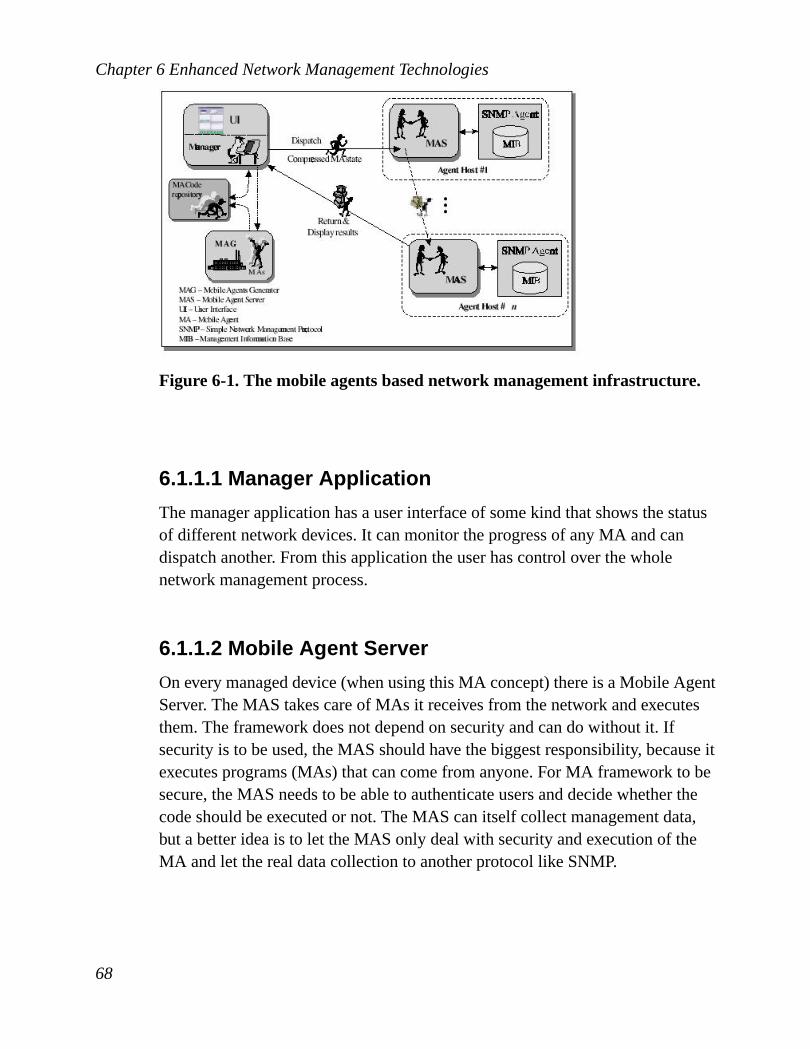
Chapter 6 Enhanced Network Management Technologies
Figure 6-1. The mobile agents based network management infrastructure.
6.1.1.1 Manager Application
The manager application has a user interface of some kind that shows the statusof different network devices. It can monitor the progress of any MA and candispatch another. From this application the user has control over the wholenetwork management process.
6.1.1.2 Mobile Agent Server
On every managed device (when using this MA concept) there is a Mobile AgentServer. The MAS takes care of MAs it receives from the network and executesthem. The framework does not depend on security and can do without it. Ifsecurity is to be used, the MAS should have the biggest responsibility, because itexecutes programs (MAs) that can come from anyone. For MA framework to besecure, the MAS needs to be able to authenticate users and decide whether thecode should be executed or not. The MAS can itself collect management data,but a better idea is to let the MAS only deal with security and execution of theMA and let the real data collection to another protocol like SNMP.
68

Chapter 6 Enhanced Network Management Technologies
6.1.1.3 Mobile Agent Generator
There must be someone or something that creates these MAs. MAs can bewritten by users that are interested in monitoring some important status or theycan be generated by other programs. These MAs are stored in a repository wherethe application can use the one it needs. Because of this flexibility - being able torun new programs on any network device - the functionality to accomplishmanagement tasks of a constantly changing network environment can bydynamically extended.
6.1.1.4 Mobile Agents
Mobile Agents are programs, but they also contain their state. When an MA getsback to the manager, after being on the network, the manager wants theinformation that the MA retrieved and the MA therefore needs state information.An MA can do one half of its work on one device and do the other half onanother device (as it does inFigure 6-1). Probably it wants to save the state fromthe first half to be able to know where to begin the work on the other device.This is another reason for MAs to also contain state.
6.1.2 SecurityMobile Agents is only a framework and therefore you can not say that it uses128-bits encryption or something like that. The security is up to theimplementation of the framework. Mobile Agents opens a new big securitythreat though, because of its ability to execute code. There must be protectionfrom unauthorized access, no unauthorized person should be able to run aprogram on the device. Even if the protection against intruders is good, there isstill a security threat from inside. The author of a MA might make a mistake andthe program might not do what she thought it would do. The MAS shouldtherefore be able to give different users different permissions and maybe thereshould be operations that not even the most privileged user could use. If theagent language supports self-modification, the authentication test might be of nouse, since the MA then can transform itself from a nice to a mean program atruntime.
69

Chapter 6 Enhanced Network Management Technologies
MAs are executable programs and it is convenient if the programs are platformindependent. Java is a popular programming language that offers platformindependent bytecode and most of the implementations of the Mobile Agentframework that exist today (and that I know of) are developed in this language.Java MAs are Java bytecode traveling around the network being run on thedifferent devices.
6.1.3 PerformanceIf Java is the implementation language, the performance is probably a little bitpoorer than if the language code can be compiled to binaries. Java bytecode isinterpreted and is therefore executed somewhat slower. There are different waysto handle the Mobile Agents. Arao et al. [ARA98] identifies three alternativeagent code transfer schemes:
• push - MA code is sent from a code repository to all the managed devicesprior to MA transfers.
• pull - MA code is loaded by the network device from a repository when theMA arrives.
• migrate - MA code is sent from one non-repository network device to another.
The migrate code scheme is the most popular one. This scheme means that allMAs contains both the code that is to be executed on a network device and thestate. In network performance, the size of the MAs have a key role. Code size istypically larger than state and the larger code size, the larger MA and the heavierIP traffic. In spite of this, the migrate code scheme is the most popular one.
6.1.4 LimitationsMobile agents are dynamic and intelligent, thus needing a flexible platform.Objects must be able to be sent between nodes in the network. C and C++ alonedo not support this, but with the help of Corba 3 [CORBA3] it is possible. Javahas support for sending object through the use of RMI. This limits the use ofmobile agents somewhat. Corba 3 might not be available for any programming
70

Chapter 6 Enhanced Network Management Technologies
language on any platform and one might not want to use Java. However, thereare no limits regarding the mobile agents framework, just the implementation.
6.1.5 AdvantagesMobile Agents framework has many advantages.
• It is easy to modify existing management functions. MAs can be deleted andadded at any time.
• Only relevant information is sent on the network and therefore network trafficis reduced. Let us say we use an SNMP management and the manager wantsthe interface usage of a device, which you calculate by(bitsafter-bitsbefore)/time. The SNMP manager then needs to poll two values(make two get requests). An MA can be sent polling the values locally,calculating the result and only the data rate is returned to the manager, thusdecreasing bandwidth use. The more values that are to be polled, the morebandwidth is saved by using Mobile Agents.
• The accuracy when calculating the data rate (bitsafter-bitsbefore)/time bypolling is non-deterministic. With SNMP polling you need first to do a getrequest to get bitsbefore value and then another get request to get the bitsaftervalue. Heavy IP traffic can cause the bitsafter value to be delayed by secondsand the time value will be wrong. Because MAs are run locally, the time isknown and the accuracy is close to perfect.
• Lower overhead when collecting values from multiple managed objects.When authentication and privacy is used, the data rate example can showmore advantages with mobile agents. In the MA case, the device only has toauthenticate once and both computer power and network traffic use isdecreased. The more polls, the more overhead. MAs mostly do not need asmany polls as for instance SNMP management.
• A manager application can launch an MA, disconnect, and collect it duringnext connection session.
• An MA can visit several devices before returning to the manager application.This saves bandwidth, especially if the devices are on other segments than the
71

Chapter 6 Enhanced Network Management Technologies
manager.
6.1.6 DisadvantagesMobile agents does not only mean improved flexibility, there are alsoadvantages:
• An MA typically contains both code (program) and state. This puts extratraffic on the network.
• Being able to execute code opens new security issues.
• MA means complex software. It requires lots of work to get a solid mobileagents platform.
6.2 Web-based ManagementIn Web-based management (WBM), Web servers are embedded in the networkdevices. One can use a Web browser to browse the configuration and status ofthe device and also to configure it.
Web servers are more intelligent than SNMP agents and can be moresophisticated. WBM uses a centralized model and suits for small offices, whosemanagement requirements are not that big. By using management applicationsyou can enhance the WBM and, for example, filter out unwanted information. Ifthere are devices on the network that use SNMP, then a Web agent can be usedas a proxy.Figure 6-2shows the WBM architecture.
72

Chapter 6 Enhanced Network Management Technologies
Figure 6-2. Embedded Web-Based Management.
A benefit of WBM is that it is easy to use, you only need a Web browser anddevices with Web agents. It is also very portable, thus there are Web browsersfor most platforms. WBM today only suits smaller offices though. One reason isthe simple client/server model that is typically used and that makes it centralizedand non-scalable. Another reason is that the communication (responds) alwaysresults in HTML files, due to the use of HTTP GET/POST requests. If you wantto analyze the results you need to parse the HTML files. XML grows inpopularity and technologies like SOAP and XML-RPC that uses XML over theHTTP protocol would probably enhance WBM systems and a distributed modelwould fit much nicer than when using HTTP/HTML.
HTML and HTTP are not well suited for polling, as they require a human topush a reload button to retrieve information and update the web page. Likewise,HTML/HTTP are not designed for accepting traps. While a Java applet may bewritten to emulate pushing the reload button or to achieveserver pushfor trapnotification, this is a workaround solution attempting to make HTML/HTTP dotasks for which they were not designed.
To be able to encrypt the network traffic between the Web browser and the Webagent, the Web agent must be able to use SSL.
73

Chapter 6 Enhanced Network Management Technologies
6.3 Web-based Enterprise ManagementThere are many standards for managing networks: SNMP, CMIP, WBM etc.Web-based Enterprise Management (WBEM) is an initiative by DesktopManagement Task Force (DMTF) trying to integrate all these standards. Thismakes the protocol used transparent to the management applications. WBEMconsists of five components: Web client, Common Information Model ObjectManager (CIMOM), CIM schema, specific management protocol providers andprotocol-specific agents.Figure 6-3shows the architecture.
Figure 6-3. WBEM architecture.
A client can send requests to any agent, using the same protocol with all theagents, the xmlCIM protocol. The client communicates with the CIMOM, whichthen transforms the request to the agent-specific protocol. When CIMOMreceives messages from the clients, it uses the information from CIM schema todetermine which protocol the managed object belongs to and switches themessage to that protocol provider. The CIM schema enables applications from
74

Chapter 6 Enhanced Network Management Technologies
different developers on different platforms to describe management data in astandard format so that it can be shared among a variety of managementapplications.
WBEM is an architecture, not an implementation. Implementations existsthough. Sun Microsystems has released a Java WBEM and implementedCIMOM with Java Management Extensions and Microsoft has its CIMOMimplementation called Windows Management Instrumentation (WMI).
6.4 Java Management ExtensionsJava Management Extensions (JMX) defines an architecture, APIs and theservices for network management in the Java programming language. JMX runson most Java-enabled devices. For a device to be Java-enabled, it needs to run aJava Virtual Machine that can interpret Java bytecode.
Almost anything can be managed using JMX: applications, services or devices.For something to be manageable it needs to embed a managed object server andmake some of its functionality available as one or several Manageable Beans(MBeans) registered in the object server. JMX provides a standard way to enablemanageability for any Java based application, service or device.
6.4.1 Architecture OverviewThe architecture is divided into three levels:
1. Instrumentation level
2. Agent level
3. Distributed services level
Figure 6-4shows this architecture.
75

Chapter 6 Enhanced Network Management Technologies
Figure 6-4. JMX architecture.
6.4.1.1 Instrumentation Level
A JMX manageable resource can be an application, a service, a device, a userand so forth. The instrumentation of a given resource is provided by one or moreMBeans. MBeans are Java objects that follows some design patterns and theJavaBeans component model. If the MBean to a given resource is registered tothe MBean server (on the agent level) then the resource can be managed by amanagement application.
MBeans are designed to be flexible, simple and easy to implement. Developersof applications, services or devices can make their products manageable in astandard way without having to understand or invest in management systems.
6.4.1.2 Agent Level
The agents control the resources and make them available to remotemanagement applications.
76
Chapter 6 Enhanced Network Management Technologies
This level makes use of the instrumentation level, in order to define astandardized way to manage JMX manageable resources. The JMX agentconsists of an MBean server and services for handling MBeans.
Managers access an agent’s MBeans and use either adaptors or connectors tocommunicate with the MBean server. The protocol adaptor gives arepresentation of MBeans in a non-JMX compliant protocol. For example, anSNMP manager that uses the SNMP protocol can manage JMX-enabled devices.Then the manager communicates with the MBean server through an SNMPprotocol adaptor. The connector interface is used with JMX compliantapplications. Various protocols that are Java compatible can use the connector,this includes protocols like Corba, RMI, HTTP and others.
6.4.1.3 Distributed Services Level
The distributed services level provides the interfaces for implementing JMXmanagers. This level defines management interfaces and components that canoperate on agents or hierarchies of agents. These components can:
• Provide an interface for management applications to interact transparentlywith an agent and its JMX manageable resources through a connector.
• Expose a management view of a JMX agent.
• Distribute management information between JMX agents and managers.
• Summarize management information coming from several JMX agents.
• Provide security.
The components can cooperate with each other to provide distributed, scalablemanagement functions, making the JMX managers appear as mid-levelmanagers.
The adaptors and connectors offer authentication and encryption.
JMX is just a specification, not an implementation. There are a fewimplementations. Sun Microsystems offers two implementations: JMXReference Implementation and Java Dynamic Management Kit (JDMK). JDMKoffers more features (like an SNMP manager API) than JMX, but JMX
77

Chapter 6 Enhanced Network Management Technologies
Reference Implementation is free and a JDMK developer license is 6000 USdollars (at the moment of this writing). There is also OpenJMX.
78

7 Existing Software for NetworkManagement
If there is good software that suits your needs, it is probably a good idea to use itin your system. Developing the piece of software is time consuming, therealways enters bugs in the code and maybe the existing software solution is muchbetter than the one you come up with. Also, existing software are well tested andoftenly work very well. So if there are any good software one can make use of inthe network management system, one should consider doing so.
7.1 SyslogGNU/Linux, FreeBSD, Solaris and many other UNIX-like operating systems usesyslogfor logging, any kind of logging. It starts at boot time, reads aconfiguration file and then runs continuously. Individual programs that need tohave information logged send the information to syslog. This centralizes thelogging. The programs do not need their own logging policy, they are all free to
79

Chapter 7 Existing Software for Network Management
use syslog.
Figure 7-1. The syslog system logging utility.
Any program can generate a syslog message and a message contains:
• Program name
• Facility
• Priority
• Actual log message
Program name is the name of the program that generated the syslog message.Facility specifies what caused the message. It is more generic than programname. There are a number of possible facilities;kernmeans that the kernelgenerated the message,usermeans that it was generated by a user,authmeansthe message was generated by a security or authorization-related process.markis a syslog internal facility used to generate timestamps. There are also otherfacilities likemail, ftp, lpr. Priority is the severity of the message. Hein et al.[HEI01] lists them:
80

Chapter 7 Existing Software for Network Management
Priority level Meaningemerg Emergency condition such as system
crash, the system is unusable.
alert Condition that should be correctedimmediately, such as a corruptedsystem database.
crit Critical condition, such as a hardwareerror.
err Ordinary error.
warning Warning message.
notice Condition that is not an error, butpossibly should be handled in a specialway.
info Informational message.
debug Messages that are used whendebugging programs.
Table 7-1. Syslog priorities.
The log message itself is in the generated message. A syslog entry can look like:
Jan 18 08:19:25 topcat sendmail[505]: [ID 702911 mail.info]
starting daemon (8.9. 3+Sun): SMTP+queueing@00:15:00
sendmailis the program that generated the message, the facility ismail andinfois the priority level. The actual log message is the last part of the message.
As can be seen inFigure 7-1, syslog not only centralizes the logging on acomputer, it centralizes the whole network logging process. Syslog can beconfigured to send the generated messages to another computer, allowing everysyslog message on the network to be stored on a single computer. This can bothease administration and improve the security. To be able to track log events, thetimestamps must be valid. Timestamps tell when the message was generated, butthey also tell in what order the events occurred. The clocks on the network’scomputers should therefore be synchronized, which can be done withrdate(remote date),timed(time server daemon) orntp (network time protocol).
The syslog daemon listens on UDP port 514 for syslog messages. As UDP is a
81
Chapter 7 Existing Software for Network Management
connectionless protocol, there is no guarantee that syslog messages sent to thenetwork syslog daemon will arrive. Under heavy traffic they can be lost. Anetwork management system can therefore not entirely rely on syslog, but it canbe a good complement. The Event Handler presented in this work can listen onUDP port 514 and log these events. But as syslog has other ways to represent thepriority and timestamp of the message, the NMSWP must know that the eventwas triggered by syslog. If it knows that, it can transform the syslog priority anddate to priority and data that the network management system understands.Syslog does not provide any security. No authentication is made, allowinganyone to send the network syslog daemon messages. A malicious host could trya DoS attack or send faked messages, confusing the network engineers. Syslogneither provides confidentiality, allowing anyone that monitors the traffic to seewhat events are sent on the network.
7.2 JiniJini technology comes from Sun Microsystems [SUN] and ties togethermachines on which Java objects are running. It enables the objects to worktogether as they were on a single computer. The objects can be activated,tracked, can communicate with each other and be managed. A user can accessall the services on the network in a location-transparent fashion.
Jini provides alookup serviceallowing services to be found. A mechanismcalleddiscovery/joinis used to achieve this. When a device joins a Jini-enablednetwork, it uses the discovery protocol to find a lookup service. When one isfound it uses the join protocol to add its services to the lookup service. When thedevice leaves the network (by being removed, being unreliable or shut down), itsservices are removed from the lookup service. The lookup service can also sendrequests to make service providers register. The lookup service serves as arepository of services and the entries are objects. These objects can bedownloaded as a part of a lookup operation and act as local proxies to the servicethat placed the code into the lookup service. If no lookup service can be found, aclient could usepeer lookupinstead. In such situations, the client can sendrequests to service providers. They will then attempt to register with the client asthough it was a lookup service. The client can then select the services it wants touse.
82

Chapter 7 Existing Software for Network Management
Jini uses a feature calledleasing. When a service registers itself to a lookupservice a time value is a part of the information being stored. The time valuedecides for how long the service will be available to the network. After thespecified time the service will be removed from the lookup directory. If theservice wants to remain available it has to renew its registration. If a service failsfor some reason, the lease soon expires and the registration will be dropped. Thisis how it handles failures. Services that fail are automatically removed from thelookup directory and another server offering the same service will be usedinstead, and this is transparent to the user.
Services can communicate with each other by using a service protocol, which isa set of interfaces. The Jini system defines a small number of such protocolswhich define critical service interactions.
Communication between services are accomplished using Remote MethodInvocation (RMI). RMI is the way Java makes remote procedure calls. It issimilar to Corba, but only works for Java.
The client is most at security risk in the Jini environment. The client brings anexternal object into its address space and runs it using all of the permissions thatit has as a process running in an operating system. So it will run under thepermissions of a particular user, in a particular directory, with user accesses tothe local file system and network. It could destroy files, make networkconnections to undesirable sites and download images from them, start processesto send obnoxious mail to anyone in your address book, and generally make amess of your electronic identity!
Security can be handled in different ways. You can grant permission only forcertain activities, such as socket access at various levels on particular ports, oraccess to certain files for reading, writing or execution. You can grant access toonly particular hosts, domains or subdomains. You can require digital signaturesattached to code. The service is probably started and associated with a user. Tolower the risks, the service should be run by a user that does not have any criticalprivileges like for instance being able to delete any file on the device. Thesesecurity precautions can be used in any combination. Digital signatures attachedto the code is the best protection for the client, but all the other mechanismsmentioned above can be used.
83
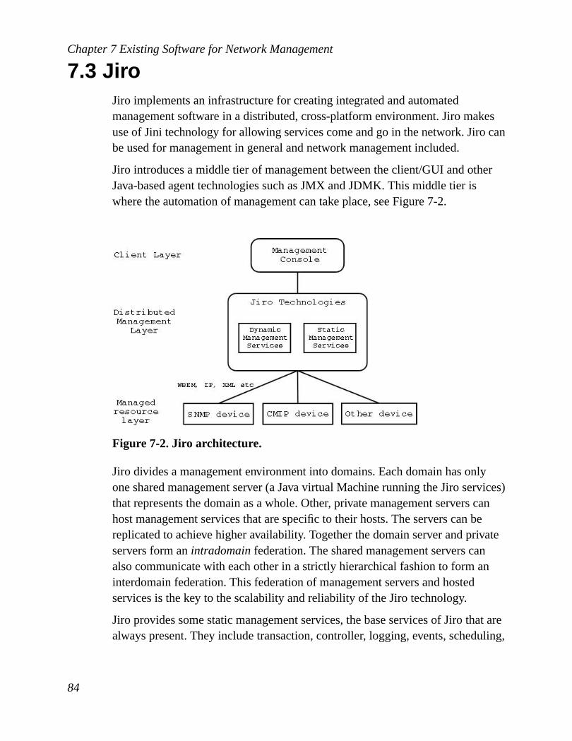
Chapter 7 Existing Software for Network Management
7.3 JiroJiro implements an infrastructure for creating integrated and automatedmanagement software in a distributed, cross-platform environment. Jiro makesuse of Jini technology for allowing services come and go in the network. Jiro canbe used for management in general and network management included.
Jiro introduces a middle tier of management between the client/GUI and otherJava-based agent technologies such as JMX and JDMK. This middle tier iswhere the automation of management can take place, seeFigure 7-2.
Figure 7-2. Jiro architecture.
Jiro divides a management environment into domains. Each domain has onlyone shared management server (a Java virtual Machine running the Jiro services)that represents the domain as a whole. Other, private management servers canhost management services that are specific to their hosts. The servers can bereplicated to achieve higher availability. Together the domain server and privateservers form anintradomainfederation. The shared management servers canalso communicate with each other in a strictly hierarchical fashion to form aninterdomain federation. This federation of management servers and hostedservices is the key to the scalability and reliability of the Jiro technology.
Jiro provides some static management services, the base services of Jiro that arealways present. They include transaction, controller, logging, events, scheduling,
84

Chapter 7 Existing Software for Network Management
lookup and security. They are available for use by the clients and servicesbelonging to a management domain.
• Transaction service is a Jini transaction manager serving a particularmanagement domain.
• Controller service provides for the reservation of ownership within themanagement domain. This allows a single point of control for managementand helps prevent inconsistent configurations.
• Log service can log decisions and state changes.
• Event service provides a set of topics to which management services can postand listen. This allows management services to react to both changingconditions in the environment and decisions that other management serviceshave made.
• Schedulingservice allows management services to perform periodic orscheduled operations, such as polling.
• Lookup service registers and locates static and dynamic Jiro servicesavailable in the management domain.
• Security service provides control over access to managed resources.
The Jiro technology and JMX complement each other. In general, Jiro focuseson the manager side, while JMX/JDMK focuses mainly on the agent side.Figure7-3shows how Jiro and JMX/JDMK complements each other.
85

Chapter 7 Existing Software for Network Management
Figure 7-3. Jiro and JMX working together.
Each managed resource provides management interface to the managementdomain. The management interface is a FederatedBeans component whichsupplies an interface from its associated resource to the domain’s managementlookup service (provided by Jini). This interface is then available to all otherresources and clients within the domain.
Resources that use existing management protocols can be integrated into the Jiroenvironment, such as WBEM and SNMP. Included in the Jiro package is also anSNMP API that makes it easy to develop SNMP manager clients.
7.4 UDDI and WSDLUniversal Description Discovery and Integration (UDDI) is a specification for alookup service. Web Services Description Language (WSDL) can be used tospecify a web service interface. These two technologies complements each other
86

Chapter 7 Existing Software for Network Management
and together they offer a service similar to Jini. Jini works best in a Javaenvironment. UDDI and WSDL, however, is built entirely on XML and istherefore programming language independent. .NET [NET] is an architecturefrom Microsoft which includes this lookup feature of web services and it isusing UDDI and WSDL. Mono [MONO] is an initiative to move the .NETplatform to GNU/Linux and other operating systems. DotGNU is an initiative ofthe FreeDevelopers [FREED] to make a free alternative to .NET. It is still indiscussion phase, but it will probably use UDDI and WSDL, too. UDDI andWSDL are relatively new on the market, but because of XML’s popularity andits use in .NET and other software, UDDI/WSDL will probably be a safe andgood choice. Adopting it for network management systems might enable anetwork management integration in a DotGNU or .NET environment.
87

Chapter 7 Existing Software for Network Management
88

8 Discussion and ConclusionsThere are many management protocols, technologies, software packages andprogramming languages to choose from. Which are chosen in this thesis aredescribed in this chapter.
8.1 ProtocolsMost devices provide SNMP agents and as SNMP has been and still is thedominating management protocol, new management systems should support thisprotocol. SNMPv1 has weaknesses, especially security weaknesses. SNMPv3adds many security features and is modularized and easily extended. The futureof SNMPv3 is uncertain, but probably it will become the new de facto standardof network management protocols.
SNMPv3 and SNMP generally, is centralized and inflexible. SNMP agents arestatic, what they offer can not be changed or easily browsed. CMIP and DMI arealso static, not very well adopted and will probably not be in the future either.Instead of static agents, dynamic, flexible and intelligent agents are desired. Thisis where we are today; dynamic and intelligent agents are being discussed anddeveloped, but they are early in research and development and it takes a whileuntil the technology is mature. Intelligent agents do not rely on managementprotocols, but introduces the concept of services. This is discussed in the sectionSection 8.2.1. To support SNMP and other protocols as well, both old and newones, one can use a proxy that receives one protocol and translates it to anyother. CIM (used in WBEM) is such a proxy protocol and is accepted and welladopted in the management world. There are converters that converts SNMPv1,SNMPv3, CMIP etc into CIM and the other way around. The design inChapter9 assumes there is a central protocol for the network management system, aprotocol that is understood by managers and that can be converted to any othermanagement protocol. This protocol is referred to as Network ManagementSystem Wide Protocol (NMSWP). One can invent a new protocol, but CIM isthe recommended choice of NMSWP.
89

Chapter 8 Discussion and Conclusions
8.2 TechnologiesBesides protocols there are also a few technologies available for networkmanagement. This section discusses whether they suit for network managementor not.
8.2.1 Mobile and Intelligent AgentsMobile and intelligent agents provide services which anyone can browse anduse. Services that a device/agent provides can be deleted or changed and servicescan be added, but only by authorized users of course. This new way of thinkingabout services suits fine in network management and is supported by JMX. If anetwork engineer wants a device to provide another service, she develops theservice and sends it to the device and when browsing the device’s services onecan immediately see and use the new service. This adds enormous flexibility to anetwork and a network management system should support this so it can beplugged in, even if it is not implemented or used at the moment. But MobileAgents adds complexity and demands more advanced security precautions.Mobile Agents is immature though. It needs more research, but the time willcome for Mobile Agents and network management systems will benefit fromthem. A complete framework for this will not be used/designed for in this thesisthough.
8.2.2 WBM and WBEMWeb-based Management and Web-based Embedded Management can be good insmall offices, where one manually can check the condition of the web serveronce in a while. It is a centralized model and builds around web pages. It is hardto make a nice graphical interface for a network management system in a webbrowser. WBM is not a good solution for a secure distributed networkmanagement system. WBEM is more sophisticated; it uses CIM so one canmanage SNMP-enabled devices and CMIP-enabled devices by only knowingone protocol. But otherwise WBEM has the same disadvantages as WBM, so itis not recommended either.
90

Chapter 8 Discussion and Conclusions
8.2.3 SolutionNone of the technologies discussed are used in this design, although CIM, whichis part of WBEM, is recommended as the NMSWP. The technologies used isinvented from scratch and builds a distributed middleware that any client canuse. How the system functions is described inSection 9.2. SNMP, CMIP andDMI devices can be integrated into the network management system, but alsointelligent/dynamic software like JMX or applications.
8.3 Programming LanguageThe choice of programming language does not affect the choice of networkmanagement protocol or design. There is one thing that Java has been able to dothat has been impossible with other programming languages (that the authorknows of) and that is the possibility to send objects through the network.Sending objects is necessary when dealing with mobile agents. A Java client canbe used to construct an MA and send it to a device. The MA can then appear asan ordinary service. This isolates the use of Java (when working with mobileagents) to the client and devices, it does not have to be used for the other parts ofthe network management system. But Java is not longer the only way to sendobjects through the network. Corba 3 [CORBA3] introduced a mechanism tosend objects through the network and as Corba is not programming languagespecific any programming language having Corba 3 support can do this. Thismakes one able to implement Mobile Agents with, for example, C++ too (C orC++ are the intended languages for this network management system).
8.4 SoftwareLarge and mid-large network management systems have to be distributed towork well. There are software packages that offers distributed services. Reuse ofexisting software is in many cases preferable. The software discussed here fallshort though. Jini and Jiro together are good software and offer lookup service,event logging, transactions, security, replication and more and builds distributed
91
Chapter 8 Discussion and Conclusions
middleware that would make a good base for a network management system.But high license costs and the case that they are Java packages makes them nogood for the solution described in this thesis. UDDI/WSDL offers a lookupservice, but the technology is too new to be recommended and used here.
Syslog is a utility for centralizing logging. Syslog is a good compliment toSNMP as intrusion detection systems, for instance, can send messages to syslogwhen someone tries to break in to the system. The network engineers willimmediately be notified about the attempt. The design presented inChapter 9supports syslog.
8.5 ServicesAll services mentioned inSection 3.5together make a complete networkmanagement system. The services function equally well in a simple NMS whereonly SNMP is used as they do in a system with intelligent Java agents. TheTransaction Service though, would probably suit best in a simple NMS. Atransaction is best performed if it can be performed by the agent itself. A Javaagent, for example, has the capability to handle transactions. However, if onewants a transaction to span over several devices, a Java agent would need aTransaction Service as well. SNMP agents do not have the same capabilities asJava agents have and there must be a Transaction Service handling thetransactions. Then all manager to agent transaction requests must take the detourthrough the Transaction Service. A Transaction Service would have to trust thatall management traffic went through this service. If a device is managedmanually or if another program for managing networks are used, the TransactionService will not be used and we can not fully rely on it. The Transaction Serviceis complex and not often used, therefore it is not designed for in this thesis.
The NMS solution this thesis presents makes use of IPSec. Therefore, theAuthentication Service does not have to be either designed for or implemented;IPSec has its own authentication system. IPSec needs authentication policy anddata stored somewhere though, so the Authentication Service can be seen as thestorage for IPSec authentication policy and data.
92

Chapter 8 Discussion and Conclusions
8.6 NOIMISThe services and clients in the system must be able to communicate with eachother and they must know how to communicate. There are several ways tocommunicate: pure sockets, Corba, SOAP, RMI etc. There must be an easy wayfor a service to store the information describing how to communicate. Thesolution presented and used in this work is the Network Object Identifier MethodInvocation String (NOIMIS). It is an ordinary string and by parsing it one cancommunicate with sockets, Corba or whatever and only one string has to bestored to be able to communicate.
A NOIMIS consists of four parts. The first part specifies what protocol to use.The first part can, for example, be "socket://" or "corba://". The second part, theNOI, identifies the network object, residing somewhere on the network, thatknows how to handle the request. The protocol and NOI part result in, forexample, "socket://193.12.214.34:56/" and"corba://www.bank.org/BankAccount" respectively. This string uniquelyidentifies the receiving object. To be able to locate the services one adds a thirdpart, the MIS, the result being "socket://193.12.214.34:56/withdrawMoney" and"corba://www.bank.org/BankAccount?withdrawMoney". To be able to specifyhow much money to withdraw one adds the last part in the NOIMIS, theparameters, resulting in"socket://193.12.214.34:56/withdrawMoney#account1#4000" or"corba://www.bank.org/BankAccount?withdrawMoney#account1#4000". Thelast part (which could be considered as a part of the MIS) consists of an arbitrarynumber of parameters, every parameter separated with a ’#’ mark. WithNOIMIS one can specify a remote method invocation with a string. This is usedin every service and manager in the network management system presented inthis work, making it flexible and easy to change the way to communicate. ANOIMIS can also be used for SNMP operations, for example"snmpv3://132.11.23.52/set#1.3.6.1.2.1.4.21.1.3.9.1.2.3#9" specifies anSNMPv3 set operation on the managed object 1.3.6.1.2.1.4.21.1.3.9.1.2.3 ondevice with IP address 132.11.23.52 and the object value would be set to 9.
libNOIMIS is a library that receives a NOIMIS and actually performs the actiondescribed by it. When the Event Handler wants to communicate with a manager,the Event Handler first passes the manager NOIMIS (that the Event Handler hasstored) to the NOIMIS library. The string is then parsed and the request is sent to
93
Chapter 8 Discussion and Conclusions
the manager.
8.7 Network ManagementHow can you know that the protocols, technologies and services discussed hereactually solves everything a network management system should solve? Thereare five management areas, each having separate goals. If those goals areachieved, we can say that the network management system presented in thiswork is a well working network management system.
8.7.1 Fault ManagementThe goals are to detect, log, isolate and fix network errors. Errors are detected bytraps from devices and Monitoring Service (e.g. RMON). The core services inthe network management system can fail themselves. Distributed functionality inevery service handles this and can report about failures to the manager (throughthe Event Handler). The errors are logged by the Event Logging Service. Theyare easily isolated by checking who triggered the trap (or other event). The eventmessage also says why the event was triggered. The Event Handler hasNOIMISes specified for all events that can happen. If an event happen, theNOIMIS tells what network object and what method should be called. ThisNOIMIS can point to a method trying to fix the actual problem, so there is thepossibility to automatically fix network errors without interaction from networkengineers.
8.7.2 Configuration ManagementThe goals of configuration management is to monitor and store network andsystem configuration information. Getting information of what software acomputer has installed is easily done with SNMP, with the command:
$ snmpwalk hostname communitystring
host.hrSWInstalled.hrSWInstalledTable.hrSWInstalledEntry.
hrSWInstalledName
94

Chapter 8 Discussion and Conclusions
A network management system’s primary goal is to detect faults, but when theyoccur it is good to know how the devices are configured. It is also good to knowhow they have been configured. If one changes the value of a managed object ona certain device and performance keeps decreasing after that, then it would begood to know the old value of the managed object to be able to restore it.
8.7.3 Security ManagementThe goal of security management is to control access to network resources sothat the network cannot be sabotaged and sensitive information cannot beaccessed without appropriate authorization. The security solution recommendedin this work is IPSec. IPSec provides confidentiality, integrity authentication andnon-repudiation. Together with a firewall, this solution will provide goodprotection. All communication between the core services are encrypted andauthenticated, allowing a network management system to manage computers allover the world. Many of the devices (printers, switches etc) that are managed cannot use IPSec. Because of that, SNMPv3 should be used whenever possible.When managing a computer or another device that can install software IPSeccan be used.
8.7.4 Performance ManagementThe goal of performance management is to measure various aspects of networkperformance so that the network performance can be maintained at an acceptablelevel. This is mostly handled by the Monitoring Service. It continuouslymonitors the network for performance issues and sends events whenperformance problems are detected. Regular reports can be sent to the networkengineers that shows how much traffic flows on the network and when the peaksare.
95

Chapter 8 Discussion and Conclusions
96

9 Suggested DesignThis design is intended for a complete network management system. Theservices that are designed are those mentioned inSection 3.5. The managementsystem is divided into modules and it is quite appropriate to have every serviceas a separate module, thus we have the following modules: Event Logging,Lookup, Event Handler, Monitoring, Protocol Proxy and History. The client maynot be defined as a service, but there should be a Client module too. As wasexplained inSection 8.5Transaction and Authentication are not designed for.
All services inherent from DistributedService class, including the clients. Allservices also (excluding clients) inherent from ReportProducer class.
Figure 9-1. Inheriting from DistributedService and ReportProducer.
The DistributedService class provides replication, recovery and fault tolerance.This means the services can be replicated, that one service can take over ifanother fails and other usable features important for availability. There is onlyone DistributedService class and it fits all services. If a service wants somethingto be handled differently, it can override the methods it inherits fromDistributedService.
The interfaces for the services are described with tables. The tables describewhat methods there are in every interface. All types are in italics.
97

Chapter 9 Suggested Design
9.1 SecurityUsing IPSec, the system will be protected from many possible attacks. IPSec isvery good in the sense that no modification of the software is needed. Thenetwork management system can be designed and implemented as if there are nosecurity threats. Traditional encryption software like SSL can be used if IPSecfor some reason is not wanted. Encryption, authentication and all other securityprecautions are then handled by the network adapters. This makes the design(except the network adapters) flexible, light and unaware of any securityprecautions, even if other security solutions than IPSec is used.
Every service can be reachable through the network and the design allows anykind of protocol to communicate with them. A service can also be used as a locallibrary, no network communication is then needed. Network adapter classeshandles the protocols and there is one adapter class for each protocol that issupported. If the client wants to use Corba to communicate with the LookupService, it talks to the CorbaAdapter class in the Lookup Service and it forwardsthe requests to the Lookup class.
All services should be remotely configurable. To not allow anyone to configurethem, the client/manager must authenticate itself. If an agent does not supporttrap authentication, the IP address of the sender can be checked to see if belongsto an authorized user. That is also considered as authentication, but is not asreliable as user/password or digital signatures.
9.2 OverviewThis section describes how the network management system is designed in ahigher level. In the next section every class is described in detail.
The design can be divided into three layers: Client, Distributed ManagementServices and Resources - seeFigure 9-2. The Distributed Management Serviceslayer can be seen as middleware - a layer of software between clients andresources providing functionality whose complexity is hidden behind a set ofAPIs. It is a complete set of distributed services for managing a network. Theclient layer involves anyone/anything that wants to make use of the middleware(except the devices). The well defined API makes the middleware easy to use.
98

Chapter 9 Suggested Design
The Resources layer includes all devices the middleware is communicating with.A resource does not have to be a physical device, it can also be a property in anapplication (although the application has to run on a device).
Figure 9-2. The network management system architecture.
9.3 Design of ModulesThe overview inFigure 9-2shows how the design is divided into layers. Thelayers themselves consist of modules. Every service in the DistributedManagement Services layer is a module. The client layer consists of only onemodule. The Resource layer is just there to show the devices, it does not reallycontain any modules. Every module consists of a number of classes. Themodules and classes are described into such detail that a software developer canimplement this network management system without having expert knowledgein the network management field.
All modules in the system has to store information on disk. What every modulehas to store is described in each module section by a subsection calledStorage.
99
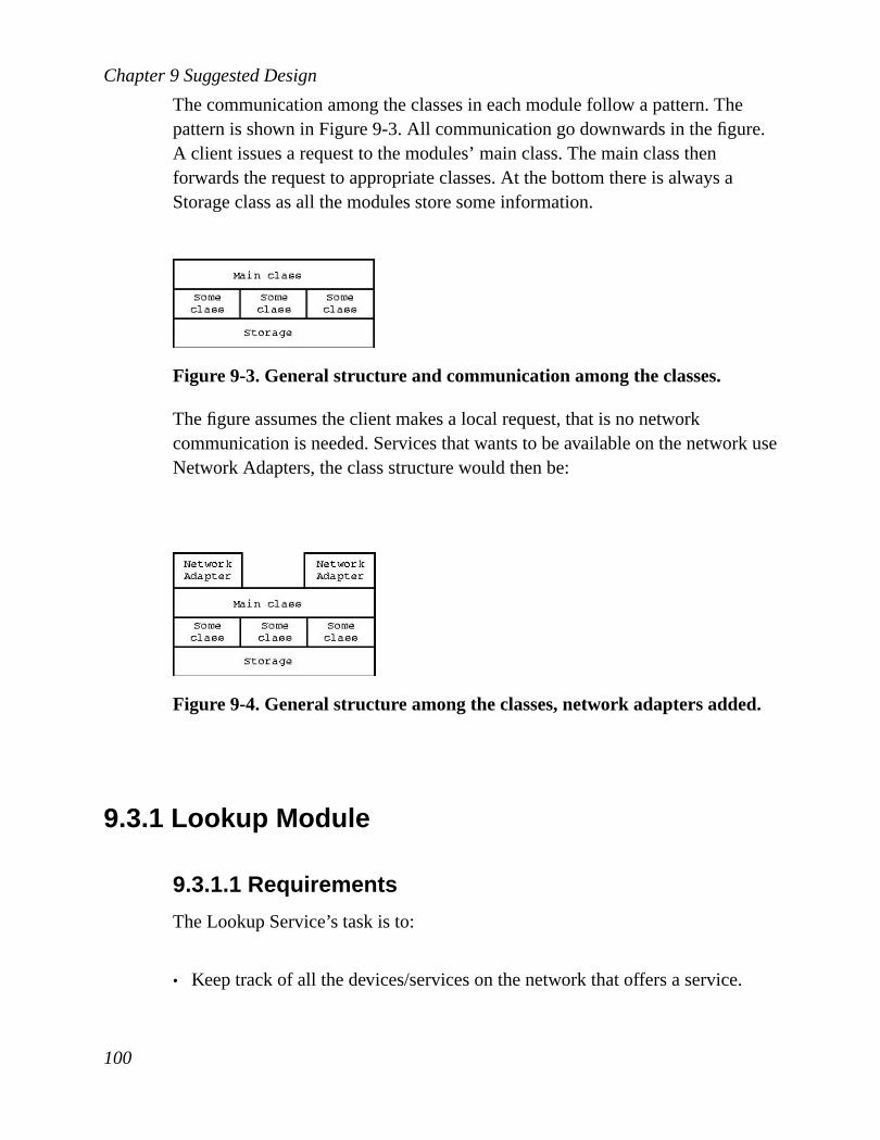
Chapter 9 Suggested Design
The communication among the classes in each module follow a pattern. Thepattern is shown inFigure 9-3. All communication go downwards in the figure.A client issues a request to the modules’ main class. The main class thenforwards the request to appropriate classes. At the bottom there is always aStorage class as all the modules store some information.
Figure 9-3. General structure and communication among the classes.
The figure assumes the client makes a local request, that is no networkcommunication is needed. Services that wants to be available on the network useNetwork Adapters, the class structure would then be:
Figure 9-4. General structure among the classes, network adapters added.
9.3.1 Lookup Module
9.3.1.1 Requirements
The Lookup Service’s task is to:
• Keep track of all the devices/services on the network that offers a service.
100

Chapter 9 Suggested Design
• Offer the management client a description of how to communicate with aservice
• Show the client the topology of the devices (optional requirement, but whichwill be designed for).
There are two ways to keep track of what devices/services are available. Oneway is to let the devices register themselves when they get plugged into thenetwork. The other way is to regularly send broadcast messages (for instanceping) on the network to see what devices respond. If a device responds, theLookup Service has to find out what services the device offers. The former is themost effective method, but that requires intelligent agents. SNMP agents areunintelligent and therefore require the second method. Both methods aresupported by this system/design.
Figure 9-5shows the steps involved when a service is used. The last step (3) isnot part of the lookup process.
Figure 9-5. The steps in a Lookup service.
9.3.1.2 Security
The lookup process involves several steps and if the service is to be totallysecure, authentication has to be performed in every step andFigure 9-5are
101

Chapter 9 Suggested Design
changed into this:
Figure 9-6. The steps in a Lookup service with authentication.
1. The first step is to register the services in the Lookup Service’s database.When a service wants to register itself it must authenticate. This protectsfrom non-authorized registering and also protects from DoS. Ifauthentication is not used in this step, anyone could register how manyservices she would like and the resources (e.g. disk space and RAM) on theLookup Service could easily be made unavailable. The first step (to registerthe service) can also be made by the Lookup Service itself. But if it wants toknow what services a device offers it has to authenticate itself. This protectsdevices from revealing their services to unauthorized users.
2. The Lookup Service authenticates itself to the client. This way the clientknows it is talking to an authorized service, a non-malicious host.
3. The client authenticates itself for the Lookup Service. The Lookup Servicethen knows it is talking to an authorized client. It also gives the LookupService the ability to show different services to different users and thatdisables certain services for certain users.
4. The client makes use of a service. This step is not involved in the lookupprocess, but is there to show a whole service-use process.
The authentication steps are handled by the VPN. If IPSec is not used, theauthentication steps has to be implemented in the network management system.This design assumes IPSec is used and all the authentication steps are handledby the VPN, they are transparent to the network management system.
102

Chapter 9 Suggested Design
If Corba or RMI are used there could be more security steps involved. When aclient performs a lookup on the Lookup Service, the Lookup Service will returna proxy object. When the proxy object is executed, how can you know that theproxy came from the device/service you actually want to use? This can be solvedwith certificates. The service can sign its proxy object before it is sent to theLookup Service and give a certificate to a Key Manager. When the client wantsto use the proxy, the client can check with the Key Manager if it is a valid one.This design does not allow proxies (because of the added security complexity).
9.3.1.3 Storage
The Lookup Service’s core is really just a database containing information aboutevery device and service on the network. For the service to be useful, mechanismlike join/release and discover are added. The database contains information ofwhat services are available and what they can perform. It also contains adescription of how every service can be used. The tables areLookup, NOI, MISandGraph. Lookup tabled is defined by three fields:
• A unique node number.
• The name and model of the device that offers the service. Example: "HPLaserJet 2000dse".
• IP address of the device.
NOI:
• A unique node number. It is used by the Lookup table to find NOIs belongingto a certain network node.
• A unique method number. It is used by the NOI table to find the MISesbelonging to a certain network object.
• Domain of which the service belongs to. A domain is just a name of a groupto which any service or client can join. It could, for example be, the string"admin".
• The name of the service. Example: "Printer".
103

Chapter 9 Suggested Design
• A description of the service. Example: "A colour 600dpi printing service".
MIS:
• A unique method number.
• A description of the method. Example: "Prints an A3 poster on an A4 printer(4 pages)".
• A parameter specification, describing what parameters the service can use.Example: "int int int,string[] string". The service can then be called eitherusing three integers or string[] as the first argument and string as the second.
• A boolean telling whether the usage of a service should be logged by theHistory Service.
The last table describes the topology of the network:
• A node number in the network.
• The number of a node that the node in the mark above communicates with.
This table shows how the devices in the network communicate, e.g. 1→ 2, 1→5, 5→ 2. This builds a three node network where node 1 points to 2 and 3 andwhere 5 points to 2.
The ER-diagram of the database looks accordingly:
104

Chapter 9 Suggested Design
Figure 9-7. ER-diagram for the Lookup database.
9.3.1.4 Classes
The Lookup Service’s core consists of seven classes: Lookup, Join, Discover,Info and Storage. There are also adapter classes that handles the communicationwith the client. The Lookup class is a spider among the classes, all clientrequests are sent to it and are then forwarded to the appropriate classes. Theclass structure looks like in the figureFigure 9-8.
Figure 9-8. The class structure and communication for the Lookup module.
105

Chapter 9 Suggested Design
Lookup Class
This is the main class, the spider of the lookup classes. It receives requests fromclients (or actually from the network adapters) and make appropriate actions.The methods included are shown inTable 9-1.
Method Parameters Return value DescriptiongetEventHandler - stringcontaining a
noimisGets the NOIMISof the closestEvent Handler onthe network.
getHistory - stringcontaining anoimis
Gets the NOIMISof the closestHistory Service onthe network.
getLogging - stringcontaining anoimis
Gets the NOIMISof the closestLogging Serviceon the network.
getMonitoring - stringcontaining anoimis
Gets the NOIMISof the closestMonitoringService on thenetwork.
getProtocolProxy - stringcontaining anoimis
Gets the NOIMISof the closestProtocol Proxy onthe network.
getSearchWords - string[] containingall searchwords
Gets availablekeywords to usefor searchingservices.
106

Chapter 9 Suggested Design
Method Parameters Return value DescriptiongetService hashtablesearch string[] containing
the service infoMaking adirectory search. Ifthere are severalmatches theLookup Servicewill return theprimary service.
registerServices stringdomain,stringname,stringdescription,stringdevice,stringnoi,string[] mis,string ip
int describingstatus of the call
Registers a service(method) to theLookup directory,making it availableto users. ThesaveHistory entryis set to false bydefault.
registerServices stringdomain,stringname,stringdescription,stringdevice,stringnoi,string[] mis,stringparameters,boolean[]saveHistory,stringip
int describingstatus of the call
Registers a service(method) to theLookup directory,making it availableto users. Everymis has acorrespondingsaveHistory.
searchService hashtablesearch string[][] makinga table of theresult
Making adirectory search,the result will bematching servicesand info aboutthem.
unregisterDevice stringdevice int describingstatus of the call
Disables andremoves allservices belongingto a certain device.
107
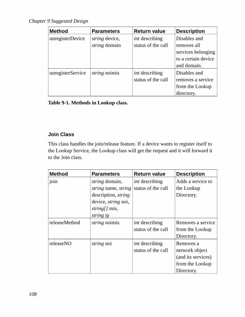
Chapter 9 Suggested Design
Method Parameters Return value DescriptionunregisterDevice stringdevice,
stringdomainint describingstatus of the call
Disables andremoves allservices belongingto a certain deviceand domain.
unregisterService stringnoimis int describingstatus of the call
Disables andremoves a servicefrom the Lookupdirectory.
Table 9-1. Methods in Lookup class.
Join Class
This class handles the join/release feature. If a device wants to register itself tothe Lookup Service, the Lookup class will get the request and it will forward itto the Join class.
Method Parameters Return value Descriptionjoin stringdomain,
stringname,stringdescription,stringdevice,stringnoi,string[] mis,string ip
int describingstatus of the call
Adds a service tothe LookupDirectory.
releaseMethod stringnoimis int describingstatus of the call
Removes a servicefrom the LookupDirectory.
releaseNO stringnoi int describingstatus of the call
Removes anetwork object(and its services)from the LookupDirectory.
108

Chapter 9 Suggested Design
Method Parameters Return value DescriptionreleaseAll stringdevice int describing
status of the callRemoves allservices from theLookup Directorythat belongs to acertain device.
releaseAll stringdevice,stringdomain
int describingstatus of the call
Removes allservices from theLookup Directorythat belongs to acertain device anddomain.
Table 9-2. Methods in Join class.
Discover Class
Most devices can not advertise themselves, therefore regular broadcast discoverymessages have to be sent on the network to find certain devices and services. TheDiscover class handles this process. The regular broadcasts can be scheduledwith help of the Scheduler class (Section 9.3.8.2).
Method Parameters Return value DescriptioncheckProtocol int protocol,string
ipbooleandescribingwhether thespecified protocolis available or not.
Checks whether adevice with acertain IP supportsCMIP, SNMP orwhatever protocolis specified.
checkServices string ip string[][]describing whatservices areavailable
Checks whatservices a deviceoffers.
109

Chapter 9 Suggested Design
Method Parameters Return value DescriptiongetTopology - string[][] building
a matrixdescribing thenetwork topology
Gets the networktopology andreturns it to theclient. The entriesin the matrixcontain an IPaddress if the twonodes (row,column) areconnected, emptyif not.
ping string ip booleandescribingwhether device isalive or not.
Asks the networkwhat devices areavailable
Table 9-3. Methods in Discover class.
Info Class
This class is invoked when a client wants information about services and how touse them. This is the class that the clients/managers will always use (by goingthrough the Lookup class) and query.
Method Parameters Return value DescriptiongetSearchWords - string[] showing
what searchwordsare available
Gets availablekeywords to usefor searchingservices.
110

Chapter 9 Suggested Design
Method Parameters Return value DescriptionsearchService hashtable
searchWordsstring[][] makinga table of theresult
Making a servicesearch, result willbe servicesmatching thesearch criteria andinfo about them.
Table 9-4. Methods in Info class.
LookupStorage Class
All classes in this module stores information. The information can be saved inany format, database, XML etc. This class contains methods to get certain partsof the stored information and hides the storage from the user.
Method Parameters Return value DescriptionaddServices stringdomain,
stringname,stringdescription,stringdevice,stringnoi,string[] mis,stringparameters,boolean[]saveHistory,stringip
int describingstatus of the call
Adds a service tothe database.
addTopology string[][] nodes int describingstatus of the call
Adds the networktopology (graph)to the database.
getSearchWords - string[] describingwhat searchwordsare available
Gets availablekeywords to usefor searchingservices.
111

Chapter 9 Suggested Design
Method Parameters Return value DescriptiongetServices - string[][]
describing theavailable services
Gets info about allavailable services.
getServices hashtablesearch string[][]describing theavailable services
Making a search inthe database, resultwill be a tablewith the matchingservices and infoabout them.
getTopology - string[][]describing thenetwork topology
Gets a table withtwo columns, IP%rarr; IP.
removeService stringnoimis int describingstatus of the call
Removes a servicewith a certainNOIMIS.
Table 9-5. Methods in LookupStorage class.
9.3.1.5 Collaboration Diagrams
A collaboration diagram showing what happens when a client wants to register
112

Chapter 9 Suggested Design
itself to the Event Handler is shown inFigure 9-9.
Figure 9-9. Collaboration diagram of what happens when a client wants touse a service.
Another collaboration diagram is shown inFigure 9-10. It shows what happenswhen a device registers itself to the Lookup Service.
Figure 9-10. Collaboration diagram of a device registering itself.
113

Chapter 9 Suggested Design
9.3.2 Event Handler ModuleThe Event Handler module and service takes care of all traps and events on thenetwork. When the Event Handler gets an SNMP trap, it will check in itsconfiguration and see to whom to forward the event to; it could be a manager, alogging service or any other service that supports the protocols and API theEvent Handler is using for forwarding events. Beside traps, the Event Handlercan receive different events from manager applications or services. TheMonitoring service can for instance send an event when it detects intrusionattempts. Clients can send events to acknowledge they have taken care of anetwork failure that earlier was reported by the Event Handler. The EventHandler can make use of the Scheduler help class to regularly remind managersabout events they have not yet acknowledged.
If syslog support is wanted for this module, the Event Handler must have adaemon listening on UDP port 514, receiving syslog messages. When a messageis received, priority and date has to be adjusted to fit into the networkmanagement system, then it can forward the event to the Event Handler class forprocessing.
9.3.2.1 Requirements
The Event Handler’s task is to:
• Receive traps from devices/services and act according to what it is configuredto do. Mostly they are forwarded to managers/clients who have registeredthemselves to the Event Handler.
• Receive events from managers and other network management services (e.g.Event Logging Service, Monitoring Service etc) and act according to what itis configured to do.
9.3.2.2 Storage
This module stores information specifying what should happen or who should benotified when receiving a certain event/trap. This could for example be stored in
114

Chapter 9 Suggested Design
a database. A database would have the tables Events, Receivers and Domains.The following information needs to be stored in Events:
• A unique integer ID identifying the entry.
• A string identifying what event it is.
• A number specifying the priority of the event.
• A number telling if and how the event should be acked.
• An integer referring to an entry in the Domains table.
In Domains it is specified what domain should be notified about what event. Thetable would look accordingly:
• A unique integer ID identifying the entry.
• The domain that wants to be notified about the event.
• A group (subdomain) in the certain domain that all will get notified of acertain event. A common group will be "managers", all managers in the samedomain should be notified of the same event.
Receivers specifies what managers and services that belong to a certain domainand that have registered that they want to be notified of certain events.
• A unique integer ID referring to an entry in the Domains table.
• The NOI of a receiver, makes it possible to communicate with it.
The ER-diagram of the database looks accordingly:
115

Chapter 9 Suggested Design
Figure 9-11. ER-diagram for the Event Handler database.
9.3.2.3 Classes
The Event Handler module consists only of the classes EventHandler andStorage. There is also the use of various protocol adapters that makes the EventHandler able to use any protocol for communication. The class structure is verysimple and looks like in figureFigure 9-12.
Figure 9-12. The class structure and communication for the Lookupmodule.
EventHandler Class
This is the main class. It receives traps and events from devices and clients andthen make appropriate actions.
116

Chapter 9 Suggested Design
Method Parameters Return value DescriptionackEvent int eventId - Tells the Event
Handler that anevent has beenacknowledged.This informationis forwarded to theEvent LoggingService and onlineclients. eventId isthe ID of the eventin the EventLogging Service.
addEvent stringnmswpEventId,stringdomain,stringgroup,stringpriority,stringack
int describingstatus of the call
Adds an event thatevery manager inthe specifieddomain and groupshould be notifiedof.
eventOccured stringnmswpEventId,string timestamp
- Tells the EventHandler that anevent occurred.
getSearchWords - string[] containingthe search words.
Tells the managerwhat search wordsare available.
117

Chapter 9 Suggested Design
Method Parameters Return value DescriptionregisterEventReceiver
string receiver,stringgroup,stringdomain
int describingstatus of the call
Registers areceiver, it willthen get eventswhen they occur.When managersare offline, there isno need to try tosend them events,but theconfigurationshould still lastwhen they log outfrom the system.Receiver isspecified by aNOI.
removeEvent stringnmswpEventId
int describingstatus of the call
Removes everyevent entrymatching withnmswpEventId.
removeEvent stringnmswpEventId,stringdomain
int describingstatus of the call
Removes thedomain from thecertain event. Thedomain will nolonger be notifiedabout the event.
removeEvent stringnmswpEventId,stringdomain,stringgroup
int describingstatus of the call
Removes thedomain and groupfrom the certainevent. Thedomain/group willno longer benotified about theevent.
118

Chapter 9 Suggested Design
Method Parameters Return value DescriptionsearchEvents hashtablesearch string[][] making
a table containingthe search result
Searches the EventHandler servicefor certain evententries, the resultis a table thatcontains the result.
unregisterEventReceiver
string receiver,stringdomain,stringgroup
int describingstatus of the call
Unregisters areceiver. Thereceiver will beremoved fromstorage and willnot be notifiedabout any events.This is typicallyused when amanager goesoffline.
Table 9-6. Methods in EventHandler class.
EventStorage Class
This is not the same class as used in the Lookup module, but has the samepurpose, to be an abstract layer (interface) that hides how the information isstored.
Method Parameters Return value DescriptionaddEvent string
nmswpEventId,stringdomain,stringgroup,stringpriority,stringack
int describingstatus of the call
Adds an event tothe database.Receiver will benotified about theevent (specified bynmswpEventId).
119

Chapter 9 Suggested Design
Method Parameters Return value DescriptionaddReceiver stringdomain,
stringgroup,stringnoi
int describingstatus of the call
Adds a receiver tothe database.Receiver will benotified about theevents that belongsto its own domain.
removeDomain stringdomain int describingstatus of the call
Removes a domainfrom the database.
removeEvent stringnmswpEvent
int describingstatus of the call
Removes an eventfrom the database.
removeReceiver string receiver int describingstatus of the call
Removes thereceiver fromdatabase.
Table 9-7. Methods in EventStorage class.
9.3.2.4 Collaboration Diagrams
A simple collaboration diagram illustrating what happens when a client wants toregister itself to the Event Handler is shown inFigure 9-13.
Figure 9-13. Collaboration diagram for a scheduled poll.
120

Chapter 9 Suggested Design
9.3.3 Event Logging Module
9.3.3.1 Requirements
The Event Logging Service’s task is to log important events on the network.Most (if not all) log requests come from the Event Handler.
9.3.3.2 Security
A logging service can easily be a victim of a DoS attack if anyone can write logsto it. Therefore authentication is necessary when issuing requests to this service.The traffic between Event Handler and Event Logging Service is mostly not topsecret and if there are performance issues encryption does not have to be used.However, the Event Logging Service gets to know almost everything thathappens on the network. The less outsiders know about the network the better.Therefore, traffic to the Event Logging Service should be encrypted if possible.
9.3.3.3 Storage
The information storage is the core of this service. All requests the EventLogging Service gets are either to store information in the database or to retrievestored information. The database contains information about what events havebeen taken place and if they have been acknowledged. When a manager comesonline it can ask the Event Logging Service if there are any events that have notbeen acknowledged and then start to investigate those. In the database case thereare two tables: Events and Acks. Events contains:
• An ID that uniquely defines the database entry.
• NMSWP ID that uniquely defines the event.
• A number telling whether the event should be acked and what ack is required(there are two types of acks). The available acks are "event notified" and"error fixed" and they are integer constants in this class. Both types of ackscan be required.
• A timestamp describing when the event occurred.
121

Chapter 9 Suggested Design
• A number telling what priority the event has.
• A message describing the event.
• IP address of the device causing the event.
Acks:
• An ID referring to the ID in the Events table.
• An event message specified by a string that describes the event.
• A timestamp that specifies when the event occured.
• The type of the ack. It can either be "event notified" or "error fixed".
• The name of the person who acked the event.
The ER-diagram is shown in figureFigure 9-14.
Figure 9-14. ER-diagram for the Event Logging database.
9.3.3.4 Classes
The Event Logging module makes use of the classes EventLogging and Storageand various network protocol adapters. The class structure is shown in figure
122

Chapter 9 Suggested Design
Figure 9-15.
Figure 9-15. The class structure and communication for the Event Handlermodule.
EventLogging Class
The EventLogging class gets requests from outside (local or through networkadapters) and calls methods in Storage class to either store information to thedatabase or retrieve information.
Method Parameters Return value DescriptiongetAcks - string[][]
describing theacks
Gets informationabout all loggedacks.
getAcks string timestamp string[][]describing theacks
Gets informationabout all loggedacks logged after acertain time.
getAcks stringsooner,string later
string[][]describing theacks
Gets informationabout all loggedacks logged withina certain timeinterval, sooner orlater beingtimestamps.
getAcksByEvent stringnmswpEvent
string[][]describing theacks
Gets informationabout all loggedacks belonging toa certain event.
123

Chapter 9 Suggested Design
Method Parameters Return value DescriptiongetAcksByEvent string
nmswpEvent,string timestamp
string[][]describing theacks
Gets informationabout all loggedacks belonging toa certain eventoccurring at acertain time.
getAcksByEvent stringnmswpEvent,stringsooner,string later
string[][]describing theacks
Gets informationabout all loggedacks belonging toa certain eventoccurring within acertain timeinterval, sooner orlater beingtimestamps.
getEvents - string[][]describing thelogging eventstable
Gets informationabout all loggedevents.
getEvents string timestamp string[][]describing a partof the loggingevents table
Gets informationabout all eventslogged after acertain time.
getEvents stringsooner,string later
string[][]describing a partof the loggingevents table
Gets informationabout all eventslogged within acertain timeinterval, sooner orlater beingtimestamps.
getEventsByIP string ip string[][]describing theevents
Gets informationabout all loggedeventscorresponding to acertain IP address.
124
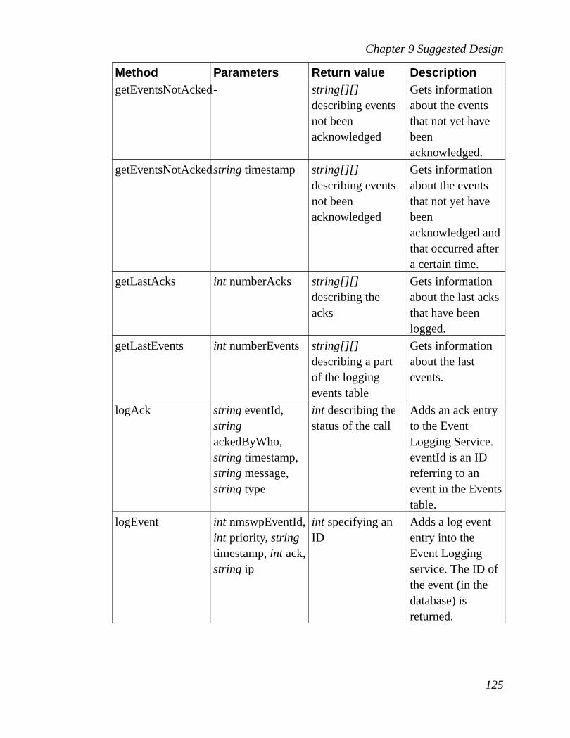
Chapter 9 Suggested Design
Method Parameters Return value DescriptiongetEventsNotAcked- string[][]
describing eventsnot beenacknowledged
Gets informationabout the eventsthat not yet havebeenacknowledged.
getEventsNotAckedstring timestamp string[][]describing eventsnot beenacknowledged
Gets informationabout the eventsthat not yet havebeenacknowledged andthat occurred aftera certain time.
getLastAcks int numberAcks string[][]describing theacks
Gets informationabout the last acksthat have beenlogged.
getLastEvents int numberEvents string[][]describing a partof the loggingevents table
Gets informationabout the lastevents.
logAck stringeventId,stringackedByWho,string timestamp,stringmessage,string type
int describing thestatus of the call
Adds an ack entryto the EventLogging Service.eventId is an IDreferring to anevent in the Eventstable.
logEvent int nmswpEventId,int priority, stringtimestamp,int ack,string ip
int specifying anID
Adds a log evententry into theEvent Loggingservice. The ID ofthe event (in thedatabase) isreturned.
125
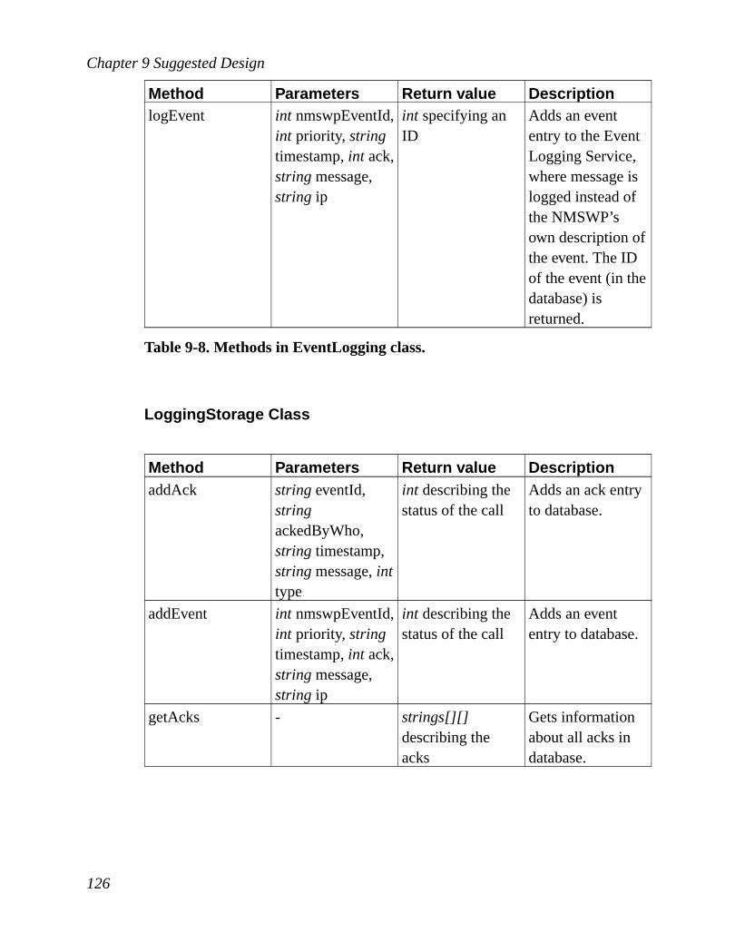
Chapter 9 Suggested Design
Method Parameters Return value DescriptionlogEvent int nmswpEventId,
int priority, stringtimestamp,int ack,stringmessage,string ip
int specifying anID
Adds an evententry to the EventLogging Service,where message islogged instead ofthe NMSWP’sown description ofthe event. The IDof the event (in thedatabase) isreturned.
Table 9-8. Methods in EventLogging class.
LoggingStorage Class
Method Parameters Return value DescriptionaddAck stringeventId,
stringackedByWho,string timestamp,stringmessage,inttype
int describing thestatus of the call
Adds an ack entryto database.
addEvent int nmswpEventId,int priority, stringtimestamp,int ack,stringmessage,string ip
int describing thestatus of the call
Adds an evententry to database.
getAcks - strings[][]describing theacks
Gets informationabout all acks indatabase.
126

Chapter 9 Suggested Design
Method Parameters Return value DescriptiongetAcks string timestamp string[][]
describing theacks
Gets informationabout all acks indatabase thatoccurred after acertain time.
getAcks stringsooner,string later
string[][]describing theacks
Gets informationabout all acks indatabase that hasbeen loggedwithin a certaintime interval,sooner or laterbeing timestamps.
getAcksByEvent stringnmswpEvent
string[][]describing theacks
Gets informationabout all acks indatabasebelonging to acertain event.
getAcksByEvent stringnmswpEvent,string timestamp
string[][]describing theacks
Gets informationabout all acks indatabasebelonging to acertain eventoccurring at acertain time.
getAcksByEvent stringnmswpEvent,stringsooner,string later
string[][]describing theacks
Gets informationabout all acks indatabasebelonging to acertain eventoccurring within acertain timeinterval, sooner orlater beingtimestamps.
127

Chapter 9 Suggested Design
Method Parameters Return value DescriptiongetEvents - string[][]
describing thelogging eventstable
Gets informationabout all events indatabase.
getEvents string timestamp string[][]describing thelogging eventstable
Gets informationabout all events indatabase loggedafter a certaintime.
getEvents stringsooner,string later
string[][]describing thelogging eventstable
Gets informationabout all events indatabase loggedwithin a certaintime interval,sooner or laterbeing timestamps.
getEventsNotAcked- string[][]describing eventsnot beenacknowledged
Gets informationabout the events inthe database thatdoes not have acorresponding ackentry.
getEventsNotAckedstring timestamp strings[][]describing eventsnot beenacknowledged
Gets informationabout the eventsthat yet not havebeenacknowledged andthat occurred aftera certain time.
getLastAcks int numberAcks string[][]describing theacks
Gets informationabout the last acksbeen logged.
128

Chapter 9 Suggested Design
Method Parameters Return value DescriptiongetLastEvents int numberEvents string[][]
describing thelogging eventstable
Gets informationabout the lastevents.
Table 9-9. Methods in LoggingStorage class.
9.3.3.5 Collaboration Diagrams
A simple collaboration diagram illustrating what happens when the EventHandler wants to log an event is shown inFigure 9-16.
Figure 9-16. Collaboration diagram showing when Event Handler logs anevent.
9.3.4 History ModuleThere are two ways to design a History Service. The first option is that theclients send all messages to a History Service which analyses the messages andthen forwards them (unchanged) to the device. If the analysis shows that themessage will change a parameter (e.g. SNMP set), then the action will be storedin history. The History Service would then need a database containing what
129

Chapter 9 Suggested Design
actions on what managed objects that should be recorded. The other option is toadd another column to theLookuptable in the Lookup Service, where each entrycontains either 0 or 1. 1 would mean that when the client uses the service, itshould send the request to the History Service. The second option moves theconfiguration from the History Service to the Lookup Service. The secondoption allows the service that registers itself to the Lookup Service to tell if itsactions should be recorded or not. The first option has the advantage that allmanagement messages can be recorded. A database containing what operationsshould be recorded or not allows the network engineers to configure the HistoryService to record certain messages, even messages that will not change anyparameter (e.g. SNMP set).
This document recommends the second option. It does not allow detailed andremote configuration; a certain operation on a certain managed object on acertain device can not be specified, but this would probably not be used veryoften anyway - the History Service’s primary goal is to store configurations.Adding a column to theLookuptable, the client will know when to send amessage to the History Service and when not to.
9.3.4.1 Requirements
The History Service’s task is to:
• Record the NMSWP messages that are sent to it.
9.3.4.2 Storage
The History Service stores:
• The NOI of the owner of the managed object.
• The NMSWP ID of the object.
• The value of the object.
• The timestamp of when the object was modified.
130

Chapter 9 Suggested Design
The ER-diagram of the simple database is shown inFigure 9-17.
Figure 9-17. ER-diagram for the history database.
9.3.4.3 Classes
This module is quite simple. It consists of the classes History and Storage. Thestructure of the classes are shown in figureFigure 9-18.
Figure 9-18. The class structure and communication for the History module.
History Class
This is the module’s main class. It gets management messages from one of thenetwork adapters and checks with theStorageclass if the messages should berecorded. If is should be recorded,Storagestores part of the message in database.
131

Chapter 9 Suggested Design
Method Parameters Return value DescriptionMethod Parameters Return value Descriptionhistory string
nmswpEventint describingstatus of the call
Asks Storage tosave the NMSWPevent.
Table 9-10. Methods in History class.
HistoryStorage Class
Method Parameters Return value DescriptionsaveHistory stringnoi, string
nmswpEventId,stringvalue
int describing thestatus of the call
Saving a messageto the database.
Table 9-11. Methods in HistoryStorage class.
9.3.4.4 Collaboration Diagrams
In Section 9.3.4two ways to design the History Service was mentioned. One ofthe solutions requires the History Service to know where to forward themessage. The History Service gets simpler if it just stores history and nothing
132

Chapter 9 Suggested Design
else, so the other solution is recommended and it is shown inFigure 9-19.
Figure 9-19. A collaboration diagram showing how to use the HistoryService.
Every message is duplicated; one message is sent to the History Service and oneis sent directly from the client (using a local Protocol Proxy) to the device. Whenthe client asks about information of the service it wants to use it also gets toknow if the messages should be recorded by the History Service.
9.3.5 Protocol Proxy ModuleProtocol Proxy module converts Corba, SNMP, CMIP etc into a protocol thatevery service understand. It can also reverse the process and convert thisprotocol to SNMP, CMIP, DMI and others. The proxy can also be used as anencryption/decryption proxy.
As SNMP and CMIP describe events and traps in different ways, we would haveto have duplicate entries in the database describing what to do if it receives anSNMP trap and what to do if it receives a CMIP trap. Having a protocolconverter, one only needs one entry in the database. Having a central protocolalso makes the client lighter; it does not have to know all possible managementprotocols, it just needs to know this very protocol.
When a manager wants to send a request to an SNMP-enabled device, it usesNMSWP instead. The manager puts together the request and sends it to the
133

Chapter 9 Suggested Design
protocol proxy. The proxy disassembles the message, converts it to an SNMPrequest and forwards it to the device. If there is the desire to convert SNMP toCMIP, one first converts SNMP to NMSWP and then converts NMSWP toCMIP.
9.3.5.1 Requirements
The Protocol Proxy’s tasks are to:
• Convert NMSWP to another protocol like SNMP, CMIP and Corba.
• Convert protocols like SNMP, CMIP and Corba to NMSWP.
• Decrypt messages that are encrypted and forward them to other device. Thedecryption part is handled by the network adapter, so the design will not showany decryption functionality.
9.3.5.2 Security
Just converting between different protocols needs no security (Chapter 4).Anyone will be able to convert CMIP messages to SNMP messages, no harmcan be done in this process.
The proxy can also be used as an encryption proxy. A client might want to sendrequests to an agent that is not able to handle encrypted traffic. The client thensends encrypted requests to the Protocol Proxy instead, which then decrypts andforwards them to the agent. This way the traffic is encrypted between the clientand protocol proxy, but not between the protocol proxy and the agent.
As all configuration information can be valuable to crackers, the informationshould be encrypted. IPSec can do this and it is transparent to the proxy (as theencryption is made in network layer).
9.3.5.3 Classes
This module is not very complex when it comes to what it actually does. It
134

Chapter 9 Suggested Design
consists of a class ProtocolProxy and various classes representing SNMP, CMIPetc. The structure of the classes are shown in figureFigure 9-20.
Figure 9-20. The class structure and communication for the Protocol Proxymodule.
ProtocolProxy Class
All client queries go through this class. First a network adapter receives arequest from the network. It forwards the request to ProtocolProxy, which in turnforwards the request to the class that knows how to handle it, for instance anSNMPv1 request is forwarded to the SNMPv1 class.
Method Parameters Return value Descriptionconvert string from, string
to, stringnmswpEvent,string receiver
stringbeing aNOIMIS, is theconverted message
Converts forexample anSNMPv1 requestto CMIP (with amiddle step ofconverting toNMSWP) and isforwarded toreceiver.
Table 9-12. Methods in ProtocolProxy class.
SNMPv1 Class
There is one class for each protocol that is able to convert to NMSWP and this is
135

Chapter 9 Suggested Design
one of them. This class includes methods both for converting SNMPv1 toNMSWP and for converting NMSWP to SNMPv1.
Method Parameters Return value DescriptionconvertFromNMSWP
stringnmswpEvent
stringcontainingthe new SNMPv1package
Converts anNMSWP requestto an SNMPrequest.
convertToNMSWPstringsnmpv1Event
stringcontainingthe new NMSWPpackage
Converts anSNMPv1 requestto an NMSWPrequest.
Table 9-13. Methods in SNMPv1 class.
9.3.5.4 Collaboration Diagrams
A client might only know the SNMPv3 protocol, but wants to configure a devicethat only knows SNMPv1. The collaboration diagram shown inFigure 9-21shows how a proxy converts the client’s SNMPv3 get request to an SNMPv1 getrequest and forwards the new message to the device.
Figure 9-21. Collaboration diagram converting SNMPv3 to SNMPv1.
136

Chapter 9 Suggested Design
9.3.6 Monitoring ModuleThis module or service is constantly capturing all data traveling on the network.A filter chooses what data to analyze and statistics are being saved in a database.That makes one able to see network performance and usage. Data being savedalso helps in detecting DoS attacks, intrusion attempts etc by, for example,analyzing patterns in traffic. Most of the capturing is done by RMON, but thisdesign also has similar functions, thus allowing the network engineers tomonitor and analyze packets that RMON does not support. This could forinstance be advanced security checks.
This module also makes regular requests to network devices for checking status.To be able to collect statistics about how the network devices do one has toregularly poll values (managed objects) from devices. For instance if one wantsto know when, during a day, a device is mostly used, one can check (poll) theusage every 5 minutes and get a nice diagram showing exactly when the peaksare. To regularly and automatically poll in certain intervals we make use of theScheduler class, which is described inSection 9.3.8.2. Polling is also usefulwhen SNMP can not send traps. If the SNMP agent can not send a trap for acertain managed object one can poll the desired managed object regularly andcheck if it is within specified limits.
9.3.6.1 Requirements
Monitoring’s task is to:
• Partly work as a sniffer or probe and capture network traffic. If the capturedtraffic show any problems of any kind, it can send events to the Event Handler.
• Regularly poll certain values (managed objects) from agents and send eventsto the Event Handler if the polled values show there are problems.
• Regularly send statistic reports, to the manager, based on the data collected bythe capturing and polling.
137

Chapter 9 Suggested Design
This service must be remotely configurable, one must be able to set filters andchoose what traffic patterns will cause events and also what managed objects topoll and how often. When analyzes show there is an intrusion attempt takingplace, this module can send an event to the Event Handler explaining what ishappening.
9.3.6.2 Storage
Data is constantly captured and some of it are stored. The storage medium canlater be scanned for finding performance issues, security violation attempts, butalso just to show statistics of traffic or device behavior.
There is a schedule telling when to poll or make a report and how to do it. Thisinformation is stored in a database. Data is polled from different networkdevices, that information is also stored in this database. When a value is polled itcan be compared to a threshold value and if it is on the wrong side of the limit,events can be sent to the Event Handler. The threshold values are specified in thedatabase. The database includes three tables. Statistics table:
• NMSWP ID, identifying what event is stored.
• A value specifying the status of the event.
• A timestamp specifying when the value was collected.
Threshold table:
• A unique integer ID, identifying the entry in the table.
• NMSWP ID, identifying the event.
• Threshold type, being a number telling if the type is ’>’, ’≥’, ’<’, ’≤’ or ’=’.’x < y < z’ is solved by having two entries.
• Threshold value, specifying what value the NMSWP status should be checkedagainst.
• Receiver of the event if ever triggered, specified by a NOIMIS.
Filter table:
138

Chapter 9 Suggested Design
• A unique integer ID, referring to the ID in the Threshold table.
• An integer telling how many times in a row the event should occur before anevent is triggered. Spontaneous events can be filtered out.
• The number of seconds that must pass between events if they should not bereported. If an event happens after another (same kind of event) within thespecified time period, the Event Handler will be informed.
The ER-diagram for this database is accordingly:
Figure 9-22. Monitor database showing only the polling part.
9.3.6.3 Security
Only authenticated users should be allowed to configure this service. Monitoringsends information about devices, performance and security alerts and otherinformation. There is no critical information flowing from Monitoring service,but it tells security vulnerabilities and condition of the system. This information
139

Chapter 9 Suggested Design
is valuable to someone trying to make intrusion attempts, so communicationbetween Monitoring service and Event Handler should be encrypted, but there isalways the option to turn it off to gain performance.
9.3.6.4 Classes
This module consists of the classes Capture, Statistics, Performance, Security,Monitoring, Storage, Polling and network specific classes. Ethernet, IP, TCP andUDP are protocols very common in the TCP/IP suite. When working in acommon LAN environment these are the protocols used and classes in thismodules are named after them. They are only used in the capturing process. Themethods of Capture, Performance, Security and network specific classes are notdescribed here. They are too complex to be investigated here. The structure andcommunication of the classes is shown in figureFigure 9-23.
Figure 9-23. The class structure and communication for the Monitoringmodule.
Capture Class
This class is responsible for capturing all traffic on the network. It then sends thepackets to the Ethernet class for analyzing. It has a main method that will startthe process of capturing network packets. How capturing is done is specific for
140

Chapter 9 Suggested Design
every operating system and it is also very complex, this class’ methods aretherefore not described.
Network Specific Classes
To make an understandable example of the data flow in this module, the networkspecific classes Ethernet, IP and TCP are used. Capture class receives all packetson the network. They are then forwarded to the Ethernet class. It knows thestructure of the Ethernet packets and knows how to interpret the bits. Thepackets get analyzed and then the configuration is checked to see what should bedone with the packets. The packets could be passed to the Statistics class forstorage or could be sent to either Security or Performance for security andperformance analyzes. When this is done the Ethernet class passes the packetsover to the IP class for further analyzing the content. Only the IP class knowshow to interpret the IP header in the packets. Depending on configuration the IPclass can determine where to forward the packets. The possible destinations arethe same as for Ethernet. The same procedure is applicable to TCP.
Statistics Class
When Ethernet, IP or TCP holds a packet that would be interesting to store forstatistic purposes, they can send it to the Statistics class and it will store theinteresting parts of the packet in a database.
Method Parameters Return value DescriptiongetStatistics - string[][]
containing thestatistics
Gets all statisticsavailable by thisservice.
getStatistics string[]nmswpEvents
string[][]containing thestatistics
Gets all statisticsbelonging to acertain event.
141

Chapter 9 Suggested Design
Method Parameters Return value DescriptiongetStatistics string[]
nmswpEvents,inttimestamp
string[][]containing thestatistics
Gets all statisticsbelonging to acertain event andoccurred in acertain timeperiod.
getStatistics string[]nmswpEvents,intsooner,int later
string[][]containing thestatistics
Gets all statisticsbelonging to acertain event thatoccurred in acertain timeinterval.
getStatistics int timestamp string[][]containing thestatistics
Gets all statisticsproduced after acertain time.
getStatistics int sooner,int later string[][]containing thestatistics
Gets all statisticsproduced in acertain timeinterval.
Table 9-14. Methods in Statistics class.
Performance Class
Various packets can be forwarded to this class. It will analyze the packets andsee if there are any performance issues on the network. If there are any problemsit can send events to the Event Handler.
Security Class
Similar to Performance its purpose is to analyze the packets, but it is looking forcertain security patterns rather than performance patterns.
142

Chapter 9 Suggested Design
Monitoring Class
The manager of the network management system must be able to read thestatistics gathered by this service and also be able to set configurations; whatpackets should be stored into statistics, what should be the threshold for thisparameter, for what values should events to the Event Handler be sent etc. Themanager/monitoring service communication is handled by this class, with helpof various protocol adapters.
Method Parameters Return value DescriptionaddThreshold string
nmswpEventId,string type,stringvalue,stringreceiver,inttimesInARow
int describingstatus of the call
Sets a thresholdfor nmswpEventIdspecifying at whatlimit to trigger anevent.
getStatistics - string[][]containing thestatistics
Gets all statisticsavailable by thisservice.
getStatistics string[]nmswpEvents
string[][]containing thestatistics
Gets all statisticsbelonging to acertain event.
getStatistics string[]nmswpEvents,intsooner,int later
string[][]containing thestatistics
Gets all statisticsbelonging to acertain event thatoccurred in acertain timeinterval.
getStatistics stringsooner,string later
string[][]containing thestatistics
Gets all statisticsproduced in acertain timeinterval.
getThresholds - string[][]containing thethresholds
Gets all thresholdinformationavailable in thisservice.
143

Chapter 9 Suggested Design
Method Parameters Return value DescriptiongetThresholds string[]
nmswpEventsstring[][]containing thethresholds
Gets all thresholdsbelonging to acertain event.
removeThreshold string[]nmswpEventIds
int describingstatus of the call
Removesthreshold from anNMSWP id.
Table 9-15. Methods in Monitoring class.
Polling Class
This class handles everything about polling. When Scheduler notices that amanaged object should be retrieved, it tells the Polling class about this. Afterthat, the Polling class polls the value and puts it into database for statistics. Italso checks the value against what it should be and if the value is out of boundsit can inform the Event Handler about this.
144
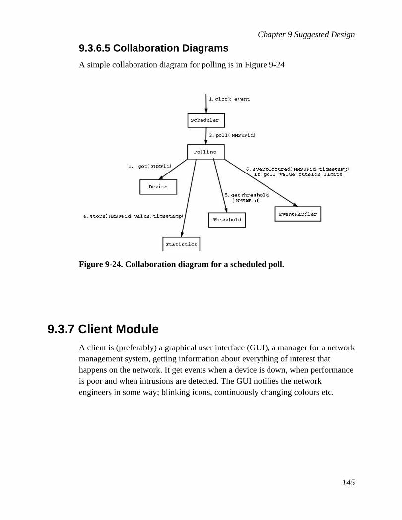
Chapter 9 Suggested Design
9.3.6.5 Collaboration Diagrams
A simple collaboration diagram for polling is inFigure 9-24
Figure 9-24. Collaboration diagram for a scheduled poll.
9.3.7 Client ModuleA client is (preferably) a graphical user interface (GUI), a manager for a networkmanagement system, getting information about everything of interest thathappens on the network. It get events when a device is down, when performanceis poor and when intrusions are detected. The GUI notifies the networkengineers in some way; blinking icons, continuously changing colours etc.
145

Chapter 9 Suggested Design
9.3.7.1 Requirements
The Client’s task is to:
• Get events and acks from the Event Handler.
• Check the Logging Service for logged events and acknowledges.
• Send chosen messages to the History Service.
• Show the events and acks in the GUI. The presentation of the events should beobvious to the network engineer. An error event must easily be detected andcolours and blinking should not be used in a way that it gets irritating to lookat the screen.
9.3.7.2 Classes
This module consists of many classes. The GUI is not described in detail, butsome suggestions are made here. A GUI designed in an object oriented languageusually have lots of classes; menu, button, every single widget is typically aclass. What GUI classes the Client module should contain are not describedhere, but classes likeGUINode, MainMenu, NodeMenu, WorkingArea,NetworkGraph, StatusDialogandHistoryDialogwould probably be convenient.The menus and dialogs inherent from the generic menu and dialogs that exist inthe GUI toolkit of choice. The non-GUI part of the module consists of theclassesClient, NodeandEvents. The structure and communication of thenon-GUI classes is shown in figureFigure 9-25.
Figure 9-25. The class structure and communication for the Client module.
146

Chapter 9 Suggested Design
Client Class
This is the main class and it provides the API for the module. All Event Handlerqueries go through this class. First an adapter receives a request from thenetwork. It forwards the request to Client, which in turn performs appropriateactions.
Method Parameters Return value Descriptionack int eventID,int
ackTypeint describing thestatus of the call
Tells the client thatanacknowledgmentof an event hasbeen made (byanother clients).
event int eventId,stringnmswpEvent,stringpriority, intackType,inteventID
int describing thestatus of the call
Tells the client thatan event hasoccurred. ackTypespecifies what typeofacknowledgmentis required for theevent.
remindEvent int nmswpEvent,int priority
int describing thestatus of the call
Tells the client thatan event earlieroccurred that hasnot yet beenacknowledged.
Table 9-16. Methods in Client class.
Events
When Client class gets an event from the network, it informs the Event classabout it. The Event class stores (in memory)eventID, nmswpEvent, priority,ackType, statusandtrigger. Status specifies whether an event has been "notify"acknowledged or "resolved" acknowledged. Trigger specifies who triggered theevent. Mostly this will be a node (device).
147
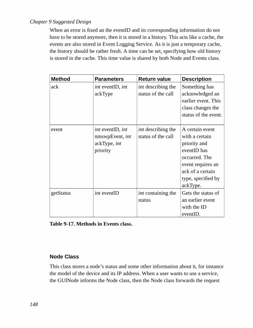
Chapter 9 Suggested Design
When an error is fixed an the eventID and its corresponding information do nothave to be stored anymore, then it is stored in a history. This acts like a cache, theevents are also stored in Event Logging Service. As it is just a temporary cache,the history should be rather fresh. A time can be set, specifying how old historyis stored in the cache. This time value is shared by both Node and Events class.
Method Parameters Return value Descriptionack int eventID,int
ackTypeint describing thestatus of the call
Something hasacknowledged anearlier event. Thisclass changes thestatus of the event.
event int eventID,intnmswpEvent,intackType,intpriority
int describing thestatus of the call
A certain eventwith a certainpriority andeventID hasoccurred. Theevent requires anack of a certaintype, specified byackType.
getStatus int eventID int containing thestatus
Gets the status ofan earlier eventwith the IDeventID.
Table 9-17. Methods in Events class.
Node Class
This class stores a node’s status and some other information about it, for instancethe model of the device and its IP address. When a user wants to use a service,the GUINode informs the Node class, then the Node class forwards the request
148

Chapter 9 Suggested Design
to the Client class, which then uses the NOIMIS to send the request to thespecified service. Node has a list of eventIDs specifying what events have not yetbeen acknowledge to the level required ("notify" or "resolved"). If Node wantsto know the status of an eventID, it can ask Events class.
When an error is fixed and the eventID does not have to be stored anymore, thenit is stored in a history. This acts like a cache, the events are also stored in EventLogging Service.
Method Parameters Return value Descriptionevent int eventID,string
messageint describing thestatus of the call
Informs the Nodeabout an event.
getDeviceInfo - string[][] forminga table containinginformation aboutthe device
Gets a history ofevents and acksbelonging to thisnode (device).
getEvents - int[] containingeventIDs
Gets the eventIDscurrent for thisnode. This istypically used byGUINode.
getHistory int last string[][] forminga table containinginformation aboutthe events andacks.
Gets the lastevents and acksbelonging to thisnode (device), thenumber of eventsand acks to get arespecified by theparameter last.
getIP - stringcontainingan IP address
Gets the IPaddress of thisnode.
getNoimis - int describing thestatus of the call
Gets the NOIMISof this node.
149

Chapter 9 Suggested Design
Method Parameters Return value DescriptiongetStatus int eventID int describing the
status of the eventGets the status ofthe specifiedevent.
statusChanged - int describing thestatus of the call
Informs the nodethat its status haschanged.
Table 9-18. Methods in Node class.
9.3.7.3 Collaboration Diagrams
The collaboration diagram inFigure 9-26shows an example of what happenswhen the Client module gets an event from the Event Handler.
Figure 9-26. Collaboration diagram showing when the client receives anevent.
Another collaboration diagram is shown inFigure 9-27. It is an example showingwhat happens when the Client module gets an ack from the Event Handler.
150

Chapter 9 Suggested Design
Figure 9-27. Collaboration diagram showing when the client receives anack.
9.3.8 Various Classes
9.3.8.1 DistributedService
All services (including the clients/managers) inherent from this class. Thismakes the services distributed. A distributed system can be quite complex, buthere only the API is shown, not the internal methods.
Method Parameters Return value Descriptionsend stringnoimis int describing the
status of the callPerforms arequest, forwardedon the network.
Table 9-19. Methods in DistributedService class.
151

Chapter 9 Suggested Design
9.3.8.2 Scheduler Class
There are several tasks that need a scheduler. All tasks that should be doneautomatically at certain times need a scheduler that starts the task. For instance,the Polling module can automate different tasks. Once every minute (could besecond, it is up to the implementation) a schedule is scanned to see if there issome device that should be polled. This can be done any time around the hourwithout interaction from any user. The functionality is similar tocrontab(thatvarious UNIX systems use), but Scheduler has the ability to make remoteinvocations instead of local commands. As it is good to use standards andunnecessary to reinvent the wheel, Scheduler uses the same way as crontab tospecify when certain tasks should be performed.
Scheduler should be able to:
• Regularly run arbitrary commands and make function calls (locally).
• Regularly make remote method invocations.
Method Parameters Return value Descriptionadd stringmonth,
stringdayOfMonth,stringdayOfWeek,stringhour,stringminute
int describing thestatus of the call
Adding an entry tothe schedule.
getAll - string[][] makinga table describingthe whole currentschedule.
Getting theschedule.
remove int entry int describing thestatus of the call
Removes the nthentry (specified bythe parameterentry) in the table.
Table 9-20. Methods in Scheduler class.
152

Chapter 9 Suggested Design
9.3.8.3 NOIMIS Class
This class has the knowledge of how NOIMIS works. If a service wants to knowthe IP of a receiver it can use this class, if it wants to communicate with anotherservice or manager it uses this class. NOIMIS is able to:
• Parse and extract information from a NOIMIS.
• Make the method invocation specified by a NOIMIS.
Method Parameters Return value DescriptiongetIP - stringcontaining
the IP address ofthe network object
Gets the IP of theNOI.
getMethod - stringcontainingthe method in theNOIMIS
Gets the methodspecified by aNOIMIS.
getNOI - stringcontainingthe NOI of theNOIMIS
Gets the NOI fromthe NOIMIS.
getParameters - string[] containingthe parameters
Gets theparameters in theNOIMIS.
NOIMIS stringnoimis - The Constructor,wanting aNOIMIS string asan argument.
send - int describing thestatus of the call
Sends an NMSWPmessage, specifiedby the internalNOIMIS.
153

Chapter 9 Suggested Design
Method Parameters Return value DescriptiontoNMSWP - stringcontaining
an NMSWPmessage
Converts theNOIMIS object toan NMSWPmessage.
Table 9-21. Methods in NOIMIS class.
9.3.8.4 ReportProducer Class
Reports can be very valuable for network engineers. Automatically getting asummary of traffic, performance and security once a week can give a goodunderstanding about the network, how it is used etc. But it is also important thatreports are short and well written, otherwise it will just be something the networkengineers throw in the trash. Reports can be of any medium, e-mail, paper,instant message etc. This class includes all methods for producing good reports.
ReportProducer should be able to:
• Regularly make reports and send them to clients.
• Be configured remotely. A client should be allowed to specify whatparameters a report should contain.
Method Parameters Return value DescriptionchangeSchedule stringmonth,
stringdayOfMonth,stringdayOfWeek,stringhour,stringminute
int describing thestatus of the call
Sets the interval,which specifieshow often thereport should besent.
154

Chapter 9 Suggested Design
Method Parameters Return value DescriptionchangeSettings string[] keys,
boolean[]valuesint describing thestatus of the call
Changes thesettings accordingto the key→ valuemappings. If onespecifies a value tofalse, thecorresponding keywill not follow thenextcomingreports.
getSettings - string[] containingthe settings
Gets the reportsettings. The clientshould be able tochange what thereports shouldcontain.
makeReport - string[][]containing thereport
Makes a report, asummary ofrelevent events andsends it to onlineclients. The reportis a table (with twocolumns) withname→ valuemappings.
send string[][] report int describing thestatus of the call
Sends the report toa client.
Table 9-22. Methods in ReportProducer class.
155

Chapter 9 Suggested Design
156

A. List of Acronyms
AES Advanced Encryption StandardAPI Application Programming InterfaceCBC Cipher Block ChainingCIM Common Information ModelCIMOM CIM Object ManagerCMIP Common Management Information
ProtocolCMIS Common Management Information
ServiceCMOT CMIP Over TCP/IPCORBA Common Object Request Broker
ArchitectureCRC Cyclic Redundancy CheckCVS Concurrent Versions SystemDES Data Encryption StandardDMI Desktop Management InterfaceDMTF Desktop Management Task ForceDoS Denial of ServiceDVD Digital Versatile DiscHTTP Hypertext Transport ProtocolICMP Internet Control Message ProtocolIEEE Institute of Electrical and Electronic
EngineersIETF Internet Engineering Task ForceIP Internet ProtocolISO International Organization for
StandardizationITU-T International Telecommunication
Union - TelecommunicationStandardization Sector
JDMK Java Dynamic Management Kit
157
Appendix A. List of Acronyms
JMX Java Management ExtensionsLAN Local Area NetworkMA Mobile AgentMAC Message Authentication CodeMIB Management Information BaseMIME Multi-Purpose Internet Mail
ExtensionsNMS Network Management SystemNMSWP Network Management System Wide
ProtocolOSI International Organization for
StandardizationOSS Operations Support SystemPDA Personal Digital AssistantPDU Packet Data UnitPING Packet Internet GrouperQoS Quality of ServiceRFC Request For CommentsNOIMIS Network Object Identifier Method
Invocation StringRMON Remote MonitoringRPC Remote Procedure CallRSA Rivest, Shamir and AdlemanSHA Secure Hash AlgorithmSMI Structure of Management InformationSNMP Simple Network Management Protocol
SOAP Simple Object Access ProtocolSSL Secure Sockets LayerTCP Transmission Control ProtocolTMN Telecommunications Management
NetworkUDP User Datagram ProtocolUSM User-based Security ModelVACM View-based Access Control Model
158

Appendix A. List of Acronyms
WBEM Web-Based Enterprise ManagementWBM Web-Based ManagementWMI Windows Management
InstrumentationXML Extensible Markup Language
159

Appendix A. List of Acronyms
160

B. List of Free Tools for NetworkManagement
Ethereal Ethereal Open SourceEthereal is a networkprotocol analyzer forUnix and Windows.
http://www.ethereal.com
libsmi A library to access SMIMIB information.
http://www.ibr.cs.tu-bs.de/projects/libsmi/
MRTG A tool to monitor thetraffic load on networklinks.
http://people.ee.ethz.ch/~oetiker/webtools/mrtg/mrtg.html
NeTraMet NeTraMet provides avaluable tool foranalysing network trafficflows, and should proveto be of interest to anyoneinterested in networkmonitoring, capacityplanning, performancemeasurement, etc.
http://www2.auckland.ac.nz/net/NeTraMet/
ntop A tool that shows thenetwork usage, similar towhat the populartopUnix command does.
http://www.ntop.org
Scotty A Tcl-based networkmanagement toolkit.
http://wwwhome.cs.utwente.nl/~schoenw/scotty/
NetSNMP Various tools relating tothe Simple NetworkManagement Protocol.
http://net-snmp.sourceforge.net/
161

Appendix B. List of Free Tools for Network Management
162

GlossaryCracker
Someone who knows how to break into a system and does not care if it is acrime.
CVS
Concurrent Versions System (CVS) is a program that lets a code developersave and retrieve different development versions of source code. It also letsa team of developers share control of different versions of files in acommon repository of files.
Kerberos
Kerberos is a secure method for authenticating a request for a service in acomputer network. Kerberos lets a user request an encrypted "ticket" froman authentication process that can then be used to request a particularservice from a server. The user’s password does not have to pass throughthe network.
Library
A software package with functions you can use from other software.
Middleware
A collection of software between clients and resources providingfunctionality whose complexity is hidden behind a set of APIs.
163

Glossary
network reference models
OSI TCP/IP7 Application Application
6 Presentation not present in thismodel
5 Session not present in thismodel
4 Transport Transport
3 Network Internet
2 Data-Link Host-to-network
1 Physical
Table 1. The OSI and TCP/IP reference models.
Peer
Another word for host.
Ping
Ping is a basic Internet program that lets you verify that a particular IPaddress exists and can accept requests. Ping is used diagnostically to ensurethat a host computer you are trying to reach is actually operating. Ping canalso be used with a host that is operating to see how long it takes to get aresponse back.
Port scan
A port scan is a series of messages sent by someone to learn whichcomputer network services the (scanned) computer provides.
164

Glossary
Server push
Server Push is a technology pioneered by Netscape and implementednatively in the Netscape Navigator browser. When a browser accesses aWeb page to obtain an image, the image is returned to the browser with aheader which contains information about the content of the image. Thisheader is in a format called MIME and is understood by all browsers. TheMIME information allows the browser to interpret the format and contentof the data.
Sniffing
Sniffing is when you monitor all the traffic flowing on the network, not justthe traffic that are meant for yourself.
Trap
A trap is a warning or error message that is sent when an unexpected orunallowable condition occur.
Tunneling
Tunneling is the process of putting one packet inside another. In IPSec anencrypted IP packet is put inside another IP packet.
165

Glossary
166

References
Books
[BLA00] Uyless Black, Prentice Hall PTR,Internet Security Protocols -Protecting IP Traffic, 2000.
[CON96] Karen Fang Conroy and Allan Leinwand, Addison Wesley,NetworkManagement - A Practical Perspective, 1996.
[GOL99] Dieter Gollman, Wiley Computer Publishing,Computer Security,1999.
[HEI01] Trent R Hein, Evi Nemeth, Scott Seebass, and Garth Snyder, PrenticeHall PTR,UNIX System Administration Handbook, 2001.
[MAN00] Scott Mann and Ellen Mitchell, Prentice Hall PTR,Linux SystemSecurity - The Administrator’s Guide to Open Source Security Tools, 2000.
[STA99] William Stallings, Prentice Hall PTR,Cryptography and NetworkSecurity, 1999.
[STAL99] William Stallings, Addison Wesley,SNMPv1, SNMPv2, SNMPv3,and RMON 1 and 2, 1999.
[SUB00] Mani Subramanian, Addison Wesley,Network Management -Principles and Practice, 2000.
[TER01] Kornel Terplan, Wiley Computer Publishing,OSS Essentials, 2001.
[ZEL99] David Zeltserman, Prentice Hall PTR,A Practical Guide to SNMPv3and Network Management, 1999.
167

References
Articles
[BEL94] S Bellovin and W Cheswick, IEEE Communications Magazine,Network Firewalls, September 1994.
[ARA98] S Arao, A Kind, J Nicklish, and J Quitteck, Net C&C ResearchLaboratories,INCA: An Agent-based Network Control Architecture, 1998.
URLs
[AES] AES Home Page, http://csrc.nist.gov/encryption/aes/, March 2002.
[AESID] Internet Draft - AES (Rijndael) Encryption Protocol with SNMPv3USM,http://www.rfc-editor.org/internet-drafts/draft-blumenthal-aes-usm-01.txt,March 2002.
[AGLETS] IBM Aglets Software Development Kit - Home Page,http://www.trl.ibm.com/aglets/, March 2002.
[CISRMON] Cisco - RMON and RMON2 Standards,http://www.cisco.com/warp/public/cc/pd/wr2k/cpbn/tech/rmon2_wp.htm,March 2002.
[CISW] Cisco Works,http://www.cisco.com/univercd/cc/td/doc/product/rtrmgmt/cw2000/index.htm,March 2002.
[CORBA3] Corba 3,http://www.omg.org/technology/corba/corba3releaseinfo.htm, March 2002.
[DIA] Dia, http://www.lysator.liu.se/~alla/dia/dia.html, March 2002.
[DNET] Distributed.net, http://www.distributed.net, March 2002.
168

References
[FREED]FreeDevelopers.net A company of free developers by free developersfor a free world, http://www.freedevelopers.net, March 2002.
[GRASS]http://www.grasshopper.de, http://www.grasshopper.de, March 2002.
[IPSEC]White Paper IPSec,http://www.cisco.com/warp/public/cc/so/neso/sqso/eqso/ipsec_wp.htm,March 2002.
[MONO] Home / Mono, http://www.go-mono.org, March 2002.
[NET] Microsoft .NET, http://www.microsoft.com/net/, March 2002.
[HPOV] HP OpenView,http://www.hp.com/products1/softwareproducts/software/openview/index.html,March 2002.
[OJADE] OpenJade, http://openjade.sourceforge.net/, March 2002.
[SOL] Solaris[tm] Product Line: Datasheets,http://www.sun.com/software/solaris/ds/ds-security/, March 2002.
[SUN] Sun Microsystems, http://www.sun.com, March 2002.
[TRYL] Tryllian, http://www.tryllian.com/, March 2002.
[VPNC] Virtual Private Network Consortium, http://www.vpnc.org, March2002.
RFCs - http://rfc.net
[RFC 768]User Datagram Protocol.
[RFC 1155]Structure and Identification of Management Information forTCP/IP-based Internets.
169
References
[RFC 1156]Management Information Base for Network Management ofTCP/IP-based internets.
[RFC 1157]A Simple Network Management Protocol (SNMP).
[RFC 1213]Management Information Base for Network Management ofTCP/IP-based internets: MIB-II.
[RFC 1441]Introduction to version 2 of the Internet-standard NetworkManagement Framework.
[RFC 1446]Security Protocols for version 2 of the Simple Network ManagementProtocol (SNMPv2).
[RFC 1902]Structure of Management Information for Version 2 of the SimpleNetwork Management Protocol (SNMPv2).
[RFC 1928]SOCKS Protocol Version 5.
[RFC 2273]SNMPv3 Applications.
[RFC 2358]Definitions of Managed Objects for the Ethernet-like InterfaceTypes.
[RFC 2401]Security Architecture for the Internet Protocol.
[RFC 2402]IP Authentication Header.
[RFC 2406]IP Encapsulating Security Payload (ESP).
[RFC 2408]Internet Security Association and Key Management Protocol(ISAKMP).
[RFC 2409]The Internet Key Exchange (IKE).
[RFC 2570]Introduction to Version 3 of the Internet-standard NetworkManagement Framework.
[RFC 2574]User-based Security Model (USM) for version 3 of the SimpleNetwork Management Protocol (SNMPv3).
170

References
[RFC 2575]View-based Access Control Model (VACM) for the Simple NetworkManagement Protocol (SNMP).
171


På svenska
Detta dokument hålls tillgängligt på Internet – eller dess framtida ersättare –under en längre tid från publiceringsdatum under förutsättning att inga extra-ordinära omständigheter uppstår.
Tillgång till dokumentet innebär tillstånd för var och en att läsa, ladda ner,skriva ut enstaka kopior för enskilt bruk och att använda det oförändrat förickekommersiell forskning och för undervisning. Överföring av upphovsrättenvid en senare tidpunkt kan inte upphäva detta tillstånd. All annan användning avdokumentet kräver upphovsmannens medgivande. För att garantera äktheten,säkerheten och tillgängligheten finns det lösningar av teknisk och administrativart.
Upphovsmannens ideella rätt innefattar rätt att bli nämnd som upphovsman iden omfattning som god sed kräver vid användning av dokumentet på ovanbeskrivna sätt samt skydd mot att dokumentet ändras eller presenteras i sådanform eller i sådant sammanhang som är kränkande för upphovsmannens litteräraeller konstnärliga anseende eller egenart.
För ytterligare information om Linköping University Electronic Press seförlagets hemsida http://www.ep.liu.se/
In English
The publishers will keep this document online on the Internet - or its possiblereplacement - for a considerable time from the date of publication barringexceptional circumstances.
The online availability of the document implies a permanent permission foranyone to read, to download, to print out single copies for your own use and touse it unchanged for any non-commercial research and educational purpose.Subsequent transfers of copyright cannot revoke this permission. All other usesof the document are conditional on the consent of the copyright owner. Thepublisher has taken technical and administrative measures to assure authenticity,security and accessibility.
According to intellectual property law the author has the right to bementioned when his/her work is accessed as described above and to be protectedagainst infringement.
For additional information about the Linköping University Electronic Pressand its procedures for publication and for assurance of document integrity,please refer to its WWW home page: http://www.ep.liu.se/
© Tim Terlegård