Embed Size (px)
Citation preview

Design of a New Model of Multiband Miniature Antenna Near Isotropic
Abdellatif Berkat1, Noureddine Boukli-Hacene2
1 Telecommunication Laboratory, Faculty of Technology, Abou-Bekr Belkaïd University Tlemcen, 13000, Algeria
2 Telecommunication Laboratory, Faculty of Technology, Abou-Bekr Belkaïd University Tlemcen, 13000, Algeria
Abstract In this paper, we propose a new slotted multiband antennas simulated at different frequencies. The insertion of slots in the patch gives a good adapting frequency with various forms on the radiation pattern. The main feature of the proposed antenna is the capability to generate a near isotropic radiation pattern in different frequencies .The design details of the conceived antenna are presented and discussed. Simulations of the different reflection coefficient and radiation pattern are presented. These were carried out using CST Microwave Studio. This model has got numerous applications in network sensors, field measurements and electromagnetic compatibility. Keywords: Multiband antenna, slot antenna, miniature antenna, near isotropic coverage, circular polarization.
1. Introduction
In recent years the rapid growth of wireless communication technologies leads to the great demands in using a multi-frequencies band on one device, because the systems want to operate at multi-frequencies in some applications such as mobile applications, pico-cell base station applications, and Wireless LAN applications. The main purpose is to reduce number of antennas in the systems. The antenna operating in multi-frequency operation band has been invented and it is called a multiband antenna [1]. However, the transmitted signal is expected to be as stable as possible, whatever the orientation of the communicating objects is. For short distance, low cost, low data rate and low consumption applications, that is to say, when an adaptive solution cannot be envisaged, the most straight-forward strategy is to search for an antenna radiating uniformly in all directions, knowing that an isotropic antenna doesn’t exist [2].
The geometry and detailed dimensions and the feeding network as well as the far-field pattern results of the proposed antenna are successively presented below.
2. Antenna structure
In this study, we propose two models of geometry with the main difference is the number of slots in the vertical patch .The antenna structure is depicted in Fig1. Six slotted patches are located along the sides of two intersected cylinders, such as, four patches on the horizontal mode and two patches on the vertical mode. As presented the following figure.
(a) (b)
Fig1-(a)Antenna with two slots in the vertical patch,(b) Antenna with tree slots in the vertical patch of the new
model Fig 2(a) illustrate the antenna structure. The green top layer is made of a low permittivity and low-loss substrate, in order to optimize the antenna efficiency and bandwidth, where ε r = 2.33, μ = 1 and thickness = 2.1 mm. A 0.7 mm thick copper layer is used as a ground plane for the antenna
IJCSI International Journal of Computer Science Issues, Vol. 8, Issue 6, No 3, November 2011 ISSN (Online): 1694-0814 www.IJCSI.org 91
structure. Fig 2(b) illustrate the horizontal patches structure ,such as, the distance between two patches on each other is 1mm. As presented the Fig 2(b) .
(a)
(b)
Fig 2-(a) Structure of the antenna with six patches, (b) Structure of the horizontal patches.
The six patches are fed with equal amplitudes. S2 and S3 are fed with the same phase of 90°. There is a phase difference of 90° between S1, (S2,S3) and S4. It presents the advantage of greatly reducing the mutual coupling between patches.
Patch number 1 and2 3and 4 5 6 Amplitude
relative to patch 1 1 1 1
Phase delay relative to patch
0° 90° 90° 180°
Table1: Amplitude and phase constraints of the antenna.
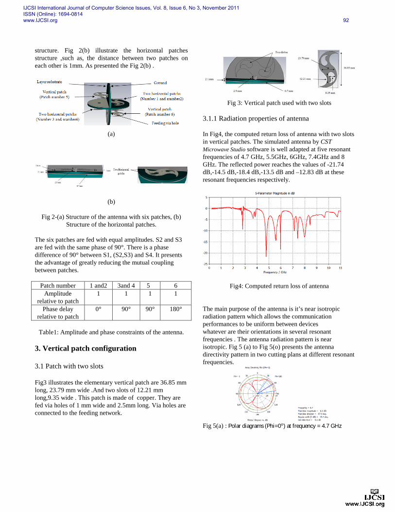
3. Vertical patch configuration 3.1 Patch with two slots Fig3 illustrates the elementary vertical patch are 36.85 mm long, 23.79 mm wide .And two slots of 12.21 mm long,9.35 wide . This patch is made of copper. They are fed via holes of 1 mm wide and 2.5mm long. Via holes are connected to the feeding network.
Fig 3: Vertical patch used with two slots
3.1.1 Radiation properties of antenna In Fig4, the computed return loss of antenna with two slots in vertical patches. The simulated antenna by CST Microwave Studio software is well adapted at five resonant frequencies of 4.7 GHz, 5.5GHz, 6GHz, 7.4GHz and 8 GHz. The reflected power reaches the values of -21.74 dB,-14.5 dB,-18.4 dB,-13.5 dB and –12.83 dB at these resonant frequencies respectively.
Fig4: Computed return loss of antenna
The main purpose of the antenna is it’s near isotropic radiation pattern which allows the communication performances to be uniform between devices whatever are their orientations in several resonant frequencies . The antenna radiation pattern is near isotropic. Fig 5 (a) to Fig 5(o) presents the antenna directivity pattern in two cutting plans at different resonant frequencies.
Fig 5(a) : Polar diagrams (Phi=0°) at frequency = 4.7 GHz
IJCSI International Journal of Computer Science Issues, Vol. 8, Issue 6, No 3, November 2011 ISSN (Online): 1694-0814 www.IJCSI.org 92

Fig 5(b) : Polar diagrams (Phi=90°) at frequency = 4.7 GHz
Fig5(c) : Polar diagrams (Theta=90°) at frequency = 4.7 GHz
Fig5(d) : Polar diagrams (Phi=0°) at frequency = 5.5 GHz
Fig5(e) : Polar diagrams (Phi=90°) at frequency = 5.5 GHz
Fig5(f) : Polar diagrams (Theta=90°) at frequency = 5.5 GHz
Fig5(g) : Polar diagrams (Phi=0°) at frequency = 6 GHz
Fig5(h) : Polar diagrams (Phi=90°) at frequency = 6 GHz
Fig5(i) : Polar diagrams (Theta=90°) at frequency = 6 GHz
Fig5(j) : Polar diagrams (Phi=0°) at frequency = 7.4 GHz
Fig5(k) : Polar diagrams (Phi=90°) at frequency = 7.4 GHz
Fig5(l) : Polar diagrams (Theta=90°) at frequency = 7.4 GHz
IJCSI International Journal of Computer Science Issues, Vol. 8, Issue 6, No 3, November 2011 ISSN (Online): 1694-0814 www.IJCSI.org 93
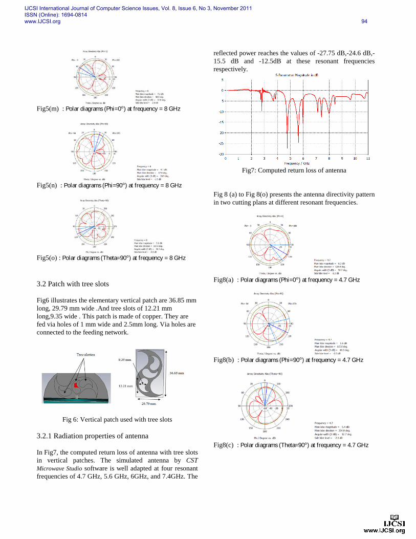
Fig5(m) : Polar diagrams (Phi=0°) at frequency = 8 GHz
Fig5(n) : Polar diagrams (Phi=90°) at frequency = 8 GHz
Fig5(o) : Polar diagrams (Theta=90°) at frequency = 8 GHz
3.2 Patch with tree slots Fig6 illustrates the elementary vertical patch are 36.85 mm long, 29.79 mm wide .And tree slots of 12.21 mm long,9.35 wide . This patch is made of copper. They are fed via holes of 1 mm wide and 2.5mm long. Via holes are connected to the feeding network.
Fig 6: Vertical patch used with tree slots 3.2.1 Radiation properties of antenna In Fig7, the computed return loss of antenna with tree slots in vertical patches. The simulated antenna by CST Microwave Studio software is well adapted at four resonant frequencies of 4.7 GHz, 5.6 GHz, 6GHz, and 7.4GHz. The
reflected power reaches the values of -27.75 dB,-24.6 dB,-15.5 dB and -12.5dB at these resonant frequencies respectively.
Fig7: Computed return loss of antenna
Fig 8 (a) to Fig 8(o) presents the antenna directivity pattern in two cutting plans at different resonant frequencies.
Fig8(a) : Polar diagrams (Phi=0°) at frequency = 4.7 GHz
Fig8(b) : Polar diagrams (Phi=90°) at frequency = 4.7 GHz
Fig8(c) : Polar diagrams (Theta=90°) at frequency = 4.7 GHz
IJCSI International Journal of Computer Science Issues, Vol. 8, Issue 6, No 3, November 2011 ISSN (Online): 1694-0814 www.IJCSI.org 94
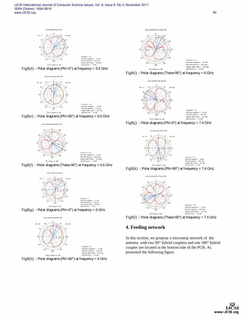
Fig8(d) : Polar diagrams (Phi=0°) at frequency = 5.6 GHz
Fig8(e) : Polar diagrams (Phi=90°) at frequency = 5.6 GHz
Fig8(f) : Polar diagrams (Theta=90°) at frequency = 5.6 GHz
Fig8(g) : Polar diagrams (Phi=0°) at frequency = 6 GHz
Fig8(h) : Polar diagrams (Phi=90°) at frequency = 6 GHz
Fig8(i) : Polar diagrams (Theta=90°) at frequency = 6 GHz
Fig8(j) : Polar diagrams (Phi=0°) at frequency = 7.4 GHz
Fig8(k) : Polar diagrams (Phi=90°) at frequency = 7.4 GHz
Fig8(l) : Polar diagrams (Theta=90°) at frequency = 7.4 GHz
4. Feeding network In this section, we propose a microstrip network of the antenna with two 90° hybrid couplers and one 180° hybrid coupler are located in the bottom side of the PCB. As presented the following figure.
IJCSI International Journal of Computer Science Issues, Vol. 8, Issue 6, No 3, November 2011 ISSN (Online): 1694-0814 www.IJCSI.org 95
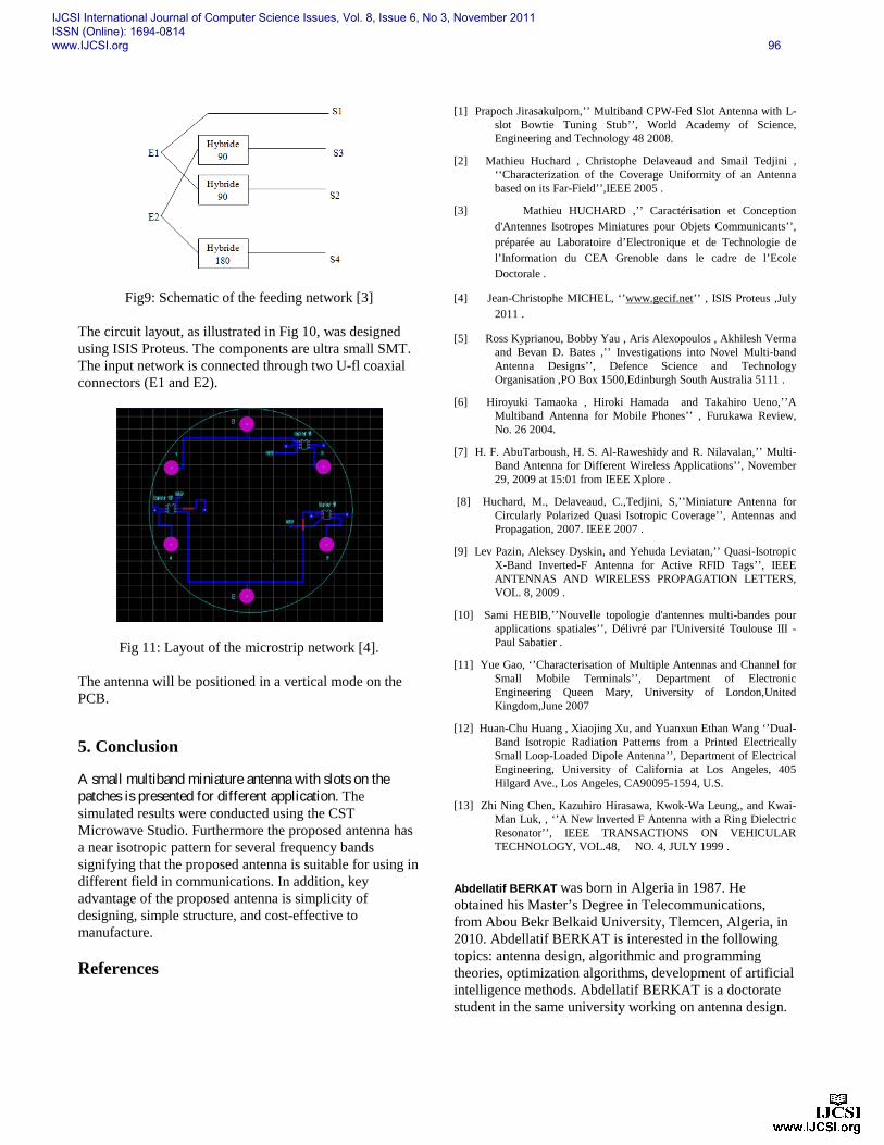
Fig9: Schematic of the feeding network [3] The circuit layout, as illustrated in Fig 10, was designed using ISIS Proteus. The components are ultra small SMT. The input network is connected through two U-fl coaxial connectors (E1 and E2).
Fig 11: Layout of the microstrip network [4].
The antenna will be positioned in a vertical mode on the PCB.
5. Conclusion
A small multiband miniature antenna with slots on the patches is presented for different application. The simulated results were conducted using the CST Microwave Studio. Furthermore the proposed antenna has a near isotropic pattern for several frequency bands signifying that the proposed antenna is suitable for using in different field in communications. In addition, key advantage of the proposed antenna is simplicity of designing, simple structure, and cost-effective to manufacture. References
[1] Prapoch Jirasakulporn,’’ Multiband CPW-Fed Slot Antenna with L-slot Bowtie Tuning Stub’’, World Academy of Science, Engineering and Technology 48 2008.
[2] Mathieu Huchard , Christophe Delaveaud and Smail Tedjini , ‘‘Characterization of the Coverage Uniformity of an Antenna based on its Far-Field’’,IEEE 2005 .
[3] Mathieu HUCHARD ,’’ Caractérisation et Conception d'Antennes Isotropes Miniatures pour Objets Communicants’’, préparée au Laboratoire d’Electronique et de Technologie de l’Information du CEA Grenoble dans le cadre de l’Ecole Doctorale .
[4] Jean-Christophe MICHEL, ‘’www.gecif.net’’ , ISIS Proteus ,July 2011 .
[5] Ross Kyprianou, Bobby Yau , Aris Alexopoulos , Akhilesh Verma and Bevan D. Bates ,’’ Investigations into Novel Multi-band Antenna Designs’’, Defence Science and Technology Organisation ,PO Box 1500,Edinburgh South Australia 5111 .
[6] Hiroyuki Tamaoka , Hiroki Hamada and Takahiro Ueno,’’A Multiband Antenna for Mobile Phones’’ , Furukawa Review, No. 26 2004.
[7] H. F. AbuTarboush, H. S. Al-Raweshidy and R. Nilavalan,’’ Multi-Band Antenna for Different Wireless Applications’’, November 29, 2009 at 15:01 from IEEE Xplore .
[8] Huchard, M., Delaveaud, C.,Tedjini, S,’’Miniature Antenna for Circularly Polarized Quasi Isotropic Coverage’’, Antennas and Propagation, 2007. IEEE 2007 .
[9] Lev Pazin, Aleksey Dyskin, and Yehuda Leviatan,’’ Quasi-Isotropic X-Band Inverted-F Antenna for Active RFID Tags’’, IEEE ANTENNAS AND WIRELESS PROPAGATION LETTERS, VOL. 8, 2009 .
[10] Sami HEBIB,’’Nouvelle topologie d'antennes multi-bandes pour applications spatiales’’, Délivré par l'Université Toulouse III - Paul Sabatier .
[11] Yue Gao, ‘’Characterisation of Multiple Antennas and Channel for Small Mobile Terminals’’, Department of Electronic Engineering Queen Mary, University of London,United Kingdom,June 2007
[12] Huan-Chu Huang , Xiaojing Xu, and Yuanxun Ethan Wang ‘’Dual-Band Isotropic Radiation Patterns from a Printed Electrically Small Loop-Loaded Dipole Antenna’’, Department of Electrical Engineering, University of California at Los Angeles, 405 Hilgard Ave., Los Angeles, CA90095-1594, U.S.
[13] Zhi Ning Chen, Kazuhiro Hirasawa, Kwok-Wa Leung,, and Kwai-Man Luk, , ‘’A New Inverted F Antenna with a Ring Dielectric Resonator’’, IEEE TRANSACTIONS ON VEHICULAR TECHNOLOGY, VOL.48, NO. 4, JULY 1999 .
Abdellatif BERKAT was born in Algeria in 1987. He obtained his Master’s Degree in Telecommunications, from Abou Bekr Belkaid University, Tlemcen, Algeria, in 2010. Abdellatif BERKAT is interested in the following topics: antenna design, algorithmic and programming theories, optimization algorithms, development of artificial intelligence methods. Abdellatif BERKAT is a doctorate student in the same university working on antenna design.
IJCSI International Journal of Computer Science Issues, Vol. 8, Issue 6, No 3, November 2011 ISSN (Online): 1694-0814 www.IJCSI.org 96

Noureddine Boukli-Hacene was born in 1959 in Tlemcen, Algeria. He received his Diplome d’Etudes Approfondies in microwave engineering (DEA Communications, Optiques et Microondes) and his Doctorate Degree in electrical engineering from Limoges University, France and from the National Center of Spatial Studies ( Centre National d’Etudes Spatiales) in Toulouse, France, in 1982 and 1985 respectively. Recently, he was appointed as a lecturer at the University of Tlemcen. His research interests include, among others, microstrip antennas and microwave circuits.
IJCSI International Journal of Computer Science Issues, Vol. 8, Issue 6, No 3, November 2011 ISSN (Online): 1694-0814 www.IJCSI.org 97