Embed Size (px)
Citation preview
Design of a 4G/LTE Multiband Antenna
978-1-5386-7333-1/18/$31.00 ©2018 Crown
Considering Curvature EffectsRolando Coto-Salazar and Renato Rimolo-Donadio
Electronics Engineering Department, Instituto Tecnologico de Costa Rica (ITCR),30101 Cartago, Costa Rica, [email protected], [email protected]
Abstract—The design, fabrication, and measurement of amultiband triangular antenna on a flexible substrate is presentedin this paper. The antenna is designed to physically adjustto the dimensions of spheric geometries and to operate inthe 4G/LTE bands. The antenna is analyzed through full-wavesimulations and return loss measurements on flat surfaces, andunder deformation in the vicinity of a spheric surface. Model-to-hardware correlation and a functional test are used to validatethe design.
Index Terms—Triangular antenna, 4G/LTE, multiband, flexi-ble, Kapton.
I. INTRODUCTION
Wearable and flexible devices gained exceptional popularitydue to their high potential in a variety of important areas suchas health care, mobile communications, and entertainment. Thedevelopment of flexible and wearable antennas has generatedparticular interest due to versatility, although design and man-ufacture are somewhat different from conventional methodsfor antennas on rigid substrates [1].
The demand for portable and wearable electronic systemsis increasing since information access requeriments are on therise. To satisfy them, wireless communication systems mustbe compact, low cost, and conformal [2]. Interest in multi-band antennas is increasing in order to respond to multipleapplications [3].
In the literature, multiple types of monopole and dipolemultiband antennas on flexible substrates have been presented,e.g. in [2], [4], due to their advantages in terms of simplic-ity, manufacturing cost, and miniaturization capacity. Planarmonopole antennas are good candidates for UWB wirelesstechnologies, because of their wide impedance bandwidth andquasi omnidireccional azimuthal radiation pattern [5]. Theseantennas can be integrated with other components on a PCBwithout the need of a back ground plane. Bow-tie or triangularantennas are usually chosen for their wider bandwidth andlarger gain [2].
In this paper, a conformal multiband antenna is presentedusing laser direct imaging (LDI) process on a Kapton sub-strate. A triangular design is adopted to achieve multiple low-reflection regions on 4G/LTE spectrum. Since a flat placementof the antenna without the interference of other devices is oftennot possible, in this work the performance of the antenna isinvestigated while it is folded on a spherical surface with aninner shield (spheric ground plane at a distance of about 1cm).
(a)
(b)
Fig. 1. Triangular multiband antenna: (a) proposed geometry with designparameters, (b) simulation model on a spherical surface.
An electromagnetic 3D model is developed to predict theantenna behavior on planar and non-planar conditions. Thesimulation model results from HFSS [6] are compared withreturn loss measurements done on a physical prototype andfurther validated with a functional test.
II. ANTENNA DESIGN & OPTIMIZATION
The proposed antenna geometry is based on the monopoleand triangular antenna designs presented in [5], [7]. Fig. 1shows the physical layout of the designed antenna.
As the antenna must have to be mechanically flexible,the material to be used must be malleable and robust toallow deformations such as bending on curved surfaces. Theflexible material must have favorable mechanical propertiesbut without compromise the electromagnetic properties, forinstance, in terms of efficiency and losses. Therefore, the
Kapton (εr=3.4 and tan(δ) = 0.0018) dielectric is selected fromthe group of PI type polymers [8].
The antenna is a triangular design with a coplanar wave-guide structure (CPW) as a feeder (fed), with 50 Ω character-istic impedance. The CPW is used because is less sensitiveto common mode interference than MS-fed. This effect iscaused by the propagation of E-field, e.g in the CPW-fed theE-field propagates parallel to surface, whereas in the MS-fedthe propagation is normal [9].
The antenna configuration is characterized by a filamentaryshaping of the top conductor plane to have inner loops withthe same shape, which are sized to respond to specific resonantfrequencies and electrical lengths. The dimensions of theproposed antenna are provided in Table I.
TABLE IDETAILED DIMENSIONS OF THE PROPOSED ANTENNA
Parameter Value (mm) Parameter Value (mm)W 43 L 122
W1 40 L1 19.6W2 40 L2 99.6W3 30 L3 93.6W4 20 L4 85.6W5 1.13 h 0.11
By increasing the length of L2, the first resonance is shiftedto lower frequencies. The length L3 of the second radiatorsets the second resonance in the intermediate band near of1.7 GHz; and the length L4 of the shortest resonator setsthe third resonance around 2 GHz. From the parametricstudy, it is determined that the antenna can be adapted to therequired frequency bands by adjusting the spacing betweenthe resonators, which corresponds to an adjust of the mutualimpedance coupling between the resonators.
The antenna, among all the other components on flexiblesubstrates, is the most susceptible to performance degradationbecause its radiation characteristic gets severely affected bydeformation and interference. It is therefore critical to studyand analyze the impact of deformation of the antenna. Anelectromagnetic model of the folded antenna is created topredict the behavior of the antenna near of the sphere withinner shield, as presented in Fig. 1(b).
The spherical model has an internal radius of 48mm andan external radius of 58mm. The material is defined as rubberand inside it has an internal structure of 4mm thick, made ofplastic that is covered by a inner conductive layer modeled asPEC. The performance of the antenna is predicted with theconfiguration shown in Fig. 1.
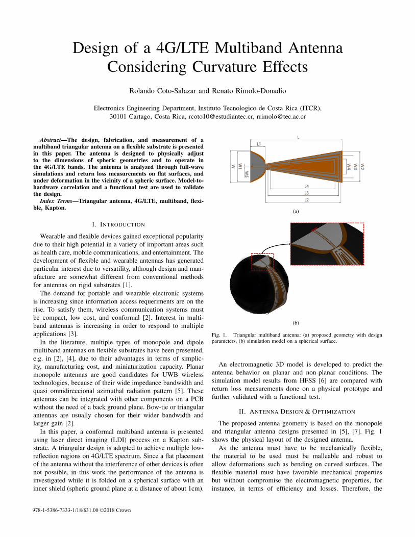
The simulated behavior of the antenna on a planar andspheric surface, in terms of return loss, is shown in Fig. 2;the simulated impedance bandwidths are shown in the TableII. From Fig. 2, it is observed that the antenna performancefor the bans of interest is reduced by physical deformation andproximity to the ground plane of the sphere. The resonanceat low frequency is shifted to even lower frequencies and theresponse in the middle band is degraded.
The antenna is capable of partially covering the 13, 14
0.5 1 1.5 2 2.5 3
Frequency [GHz]
-25
-20
-15
-10
-5
0
Ma
gn
itu
de
[d
B]
-6 dB
-10 dB
Flat
Bent
Fig. 2. Simulated |S11| curves for the triangular antenna with and withoutdeformation.
TABLE IISIMULATED FREQUENCY BANDS COVERED BY THE PROPOSED ANTENNA
Model Bandwidth (MHz) 4G/LTEcovered bands-6 dB -10 dB
Flat759-1120 811-994 1, 2, 3, 4,
5, 10, 13, 141565-2406 1593-22802574-2753 2599-2676
Bent 566-805 608-740 1, 2, 3, 4, 1012, 13, 14, 171530-2935 2662-3000
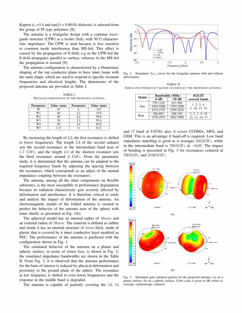
and 17 band of US700; also, it covers CCDMA, AWS, andGSM. This is an advantage if hand-off is required. Low bandimpedance matching is good as it averages 342MHz, whilein the intermediate band is 760MHz at ´6dB. The impactof bending is presented in Fig. 3 for resonances centered at700MHz and 2100MHz.
(a)
(b)
Fig. 3. Simulated gain radiation pattern for the proposed antenna: (a) on aplanar surface, (b) on a spheric surface. Color scale is given in dB (refers toisotropic radiatortropic radiator).
The antenna radiation characteristic resembles nearly omni-directional radiation patterns, which guarantee good detectionand reception capability of radiated signals from any direction.The maximum peak gain is 1.67 dB for 700 MHz, 3.02 dBfor 1700 MHz, and 4.80 dB for 2100 MHz. Note that byknowing the position of the antenna in advance, the designcould be adjusted to work in particular bands.
III. MODEL TO HARDWARE CORRELATION
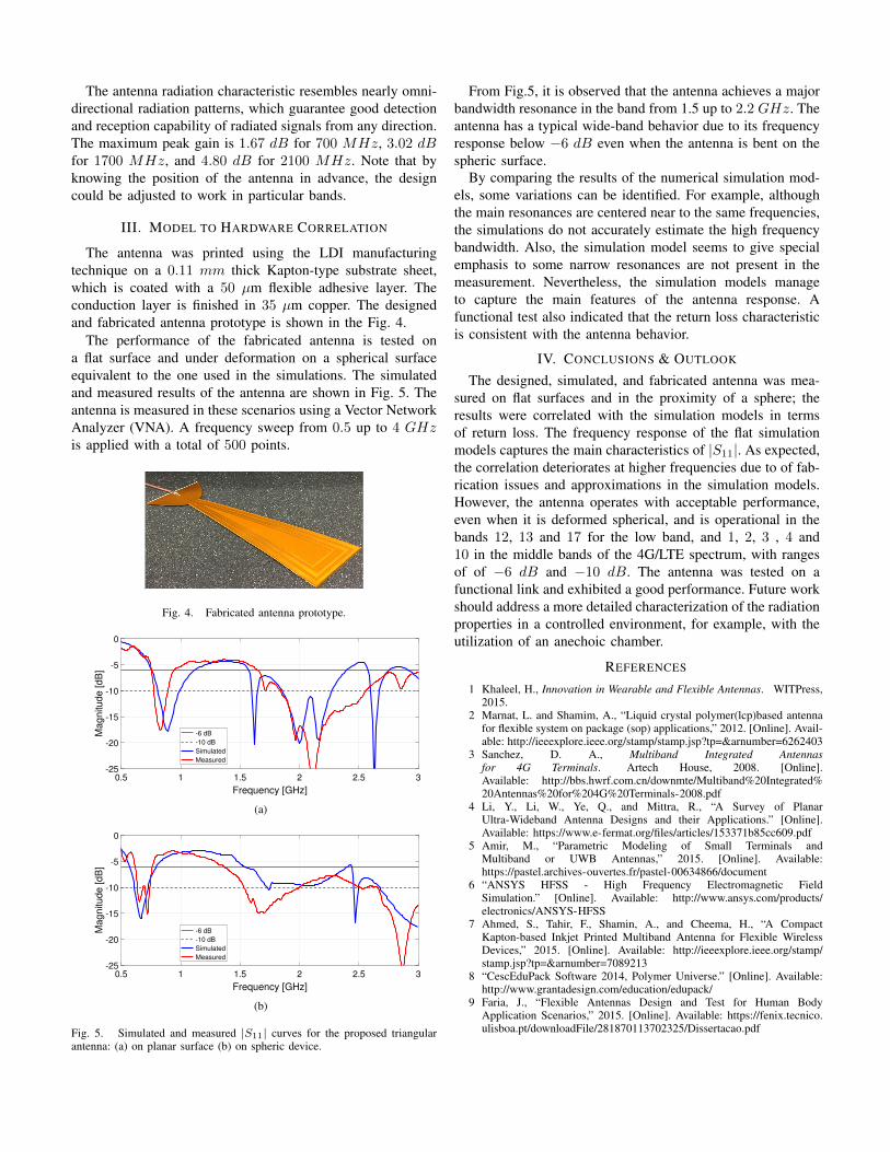
The antenna was printed using the LDI manufacturingtechnique on a 0.11 mm thick Kapton-type substrate sheet,which is coated with a 50 µm flexible adhesive layer. Theconduction layer is finished in 35 µm copper. The designedand fabricated antenna prototype is shown in the Fig. 4.
The performance of the fabricated antenna is tested ona flat surface and under deformation on a spherical surfaceequivalent to the one used in the simulations. The simulatedand measured results of the antenna are shown in Fig. 5. Theantenna is measured in these scenarios using a Vector NetworkAnalyzer (VNA). A frequency sweep from 0.5 up to 4 GHzis applied with a total of 500 points.
Fig. 4. Fabricated antenna prototype.
0.5 1 1.5 2 2.5 3
Frequency [GHz]
-25
-20
-15
-10
-5
0
Ma
gn
itu
de
[d
B]
-6 dB
-10 dB
Simulated
Measured
(a)
0.5 1 1.5 2 2.5 3
Frequency [GHz]
-25
-20
-15
-10
-5
0
Ma
gn
itu
de
[d
B]
-6 dB
-10 dB
Simulated
Measured
(b)
Fig. 5. Simulated and measured |S11| curves for the proposed triangularantenna: (a) on planar surface (b) on spheric device.
From Fig.5, it is observed that the antenna achieves a majorbandwidth resonance in the band from 1.5 up to 2.2 GHz. Theantenna has a typical wide-band behavior due to its frequencyresponse below ´6 dB even when the antenna is bent on thespheric surface.
By comparing the results of the numerical simulation mod-els, some variations can be identified. For example, althoughthe main resonances are centered near to the same frequencies,the simulations do not accurately estimate the high frequencybandwidth. Also, the simulation model seems to give specialemphasis to some narrow resonances are not present in themeasurement. Nevertheless, the simulation models manageto capture the main features of the antenna response. Afunctional test also indicated that the return loss characteristicis consistent with the antenna behavior.
IV. CONCLUSIONS & OUTLOOK
The designed, simulated, and fabricated antenna was mea-sured on flat surfaces and in the proximity of a sphere; theresults were correlated with the simulation models in termsof return loss. The frequency response of the flat simulationmodels captures the main characteristics of |S11|. As expected,the correlation deteriorates at higher frequencies due to of fab-rication issues and approximations in the simulation models.However, the antenna operates with acceptable performance,even when it is deformed spherical, and is operational in thebands 12, 13 and 17 for the low band, and 1, 2, 3 , 4 and10 in the middle bands of the 4G/LTE spectrum, with rangesof of ´6 dB and ´10 dB. The antenna was tested on afunctional link and exhibited a good performance. Future workshould address a more detailed characterization of the radiationproperties in a controlled environment, for example, with theutilization of an anechoic chamber.
REFERENCES
1 Khaleel, H., Innovation in Wearable and Flexible Antennas. WITPress,2015.
2 Marnat, L. and Shamim, A., “Liquid crystal polymer(lcp)based antennafor flexible system on package (sop) applications,” 2012. [Online]. Avail-able: http://ieeexplore.ieee.org/stamp/stamp.jsp?tp=&arnumber=6262403
3 Sanchez, D. A., Multiband Integrated Antennasfor 4G Terminals. Artech House, 2008. [Online].Available: http://bbs.hwrf.com.cn/downmte/Multiband%20Integrated%20Antennas%20for%204G%20Terminals-2008.pdf
4 Li, Y., Li, W., Ye, Q., and Mittra, R., “A Survey of PlanarUltra-Wideband Antenna Designs and their Applications.” [Online].Available: https://www.e-fermat.org/files/articles/153371b85cc609.pdf
5 Amir, M., “Parametric Modeling of Small Terminals andMultiband or UWB Antennas,” 2015. [Online]. Available:https://pastel.archives-ouvertes.fr/pastel-00634866/document
6 “ANSYS HFSS - High Frequency Electromagnetic FieldSimulation.” [Online]. Available: http://www.ansys.com/products/electronics/ANSYS-HFSS
7 Ahmed, S., Tahir, F., Shamin, A., and Cheema, H., “A CompactKapton-based Inkjet Printed Multiband Antenna for Flexible WirelessDevices,” 2015. [Online]. Available: http://ieeexplore.ieee.org/stamp/stamp.jsp?tp=&arnumber=7089213
8 “CescEduPack Software 2014, Polymer Universe.” [Online]. Available:http://www.grantadesign.com/education/edupack/
9 Faria, J., “Flexible Antennas Design and Test for Human BodyApplication Scenarios,” 2015. [Online]. Available: https://fenix.tecnico.ulisboa.pt/downloadFile/281870113702325/Dissertacao.pdf