Embed Size (px)
Citation preview

University of Pennsylvania University of Pennsylvania
ScholarlyCommons ScholarlyCommons
Technical Reports (CIS) Department of Computer & Information Science
January 1995
Design, Implementation and Experiences of the OMEGA End-Point Design, Implementation and Experiences of the OMEGA End-Point
Architecture Architecture
Klara Nahrstedt University of Pennsylvania
Jonathan M. Smith University of Pennsylvania, [email protected]
Follow this and additional works at: https://repository.upenn.edu/cis_reports
Recommended Citation Recommended Citation Klara Nahrstedt and Jonathan M. Smith, "Design, Implementation and Experiences of the OMEGA End-Point Architecture", . January 1995.
University of Pennsylvania Department of Computer and Information Science Technical Report No. MS-CIS-95-22.
This paper is posted at ScholarlyCommons. https://repository.upenn.edu/cis_reports/217 For more information, please contact [email protected].
Design, Implementation and Experiences of the OMEGA End-Point Architecture Design, Implementation and Experiences of the OMEGA End-Point Architecture
Abstract Abstract New cell-switched network technologies and multimedia peripherals enable distributed applications with strict real-time requirements such as remote control with feedback. Time-bounded network communications services are necessary, but not sufficient, to meet application-to-application real-time requirements. Real-time communication must be coupled with real-time computing support at the network end-points. An end-point architecture for the computation/communications coupling must be flexible and robust to support a diversity of applications.
The OMEGA architecture, when coupled with cell-switched networks (or others which can make bandwidth and delay guarantees), can approximate the behavior of dedicated microcontrollers connected by dedicated circuits in support of an application. The essence of the OMEGA architecture is resource reservation and management within the set of multimedia endpoints. Communications is preceded by a call set-up period where requirements, expressed in terms of Quality of Service (QoS) parameters, are negotiated, and guarantees are made at several logical levels, such as between applications and the network subsystem, applications and the operating system, and the network subsystem and the operating system. This establishes customized connections and allocation of resources appropriate to the application requirements and OS/network capabilities. To facilitate this resource management process, a new paradigm called the 'QoS Brokerage' is used. This paradigm requires new services and protocols across all layers of the protocol stack (i.e., the higher layers of B-ISDN), as well as re-architecting the application/network interface.
A prototype of OMEGA has been implemented and tested with a master/slave telerobotics application using a dedicated 155 Mbps ATM LAN. This application employs media with highly diverse QoS requirements and therefore provides a good platform for testing how closely one can approximate a dedicated circuit and controller with workstation hosts and cell-switching. Experience with this implementation has helped to identify new challenges to extending these techniques to a larger domain of applications and systems, and raises several new research questions.
Comments Comments University of Pennsylvania Department of Computer and Information Science Technical Report No. MS-CIS-95-22.
This technical report is available at ScholarlyCommons: https://repository.upenn.edu/cis_reports/217
Design, Implementation and Experiences of the OMEGA End-Point Architecture
MS-CIS-95-22
Klara Nahrstedt and Jonathan M. Smith
University of Pennsylvania School of Engineering and Applied Science
Computer and Information Science Department
Philadelphia, PA 19104-6389
'Research support for this work came from Bellcore (through Project DAWN), IBM, Hewlett- Packard, and from the Corporation for National Research Initiatives (CNRI), which is funded by the National Science Foundation and the Defense Advanced Research Projects Agency under cooperative agreement #NCR-8919038.
Design, Implementation and Experiences of the OMEGA End-Point Architecture
Klara Nahrstedt and Jonathan M. S m i t h *
Distributed S y s t e m s Laboratory University of Pennsylvania, Philadelphia, PA 191 04-6389
Abs t r ac t
New cell-switched network technologies and multimedia peripherals enable distributed ap- plications with strict real-time requirements such as remote control with feedback. Time- bounded network communications services are necessary, but not sufficient, t o meet application- to-application real-time requirements. Real-time communication must be coupled with real-time computing support at the network end-points. An end-point architecture for this computa- tion/communications coupling must be flexible and robust to support a diversity of applications.
The OMEGA architecture, when coupled with cell-switched networks (or others which can make bandwidth and delay guarantees), can approximate the behavior of dedicated microcon- trollers connected by dedicated circuits in support of an application. The essence of the OMEGA architecture is resource reservation and management within the set of multimedia endpoints. Communications is preceded by a call-set up period where requirements, expressed in terms of Quality of Service (QoS) parameters, are negotiated, and guarantees are made at several logical levels, such as between applications and the network subsystem, applications and the operating system, and the network subsystem and the operating system. This establishes cus- tomized connections and allocation of resources appropriate to the application requirements and OS/network capabilities. To facilitate this resource management process, a new paradigm called the 'QoS Brokerage' is used. This paradigm requires new services and protocols across all layers of the protocol stack (i.e., the higher layers of B-ISDN), as well as rearchitecting the application/network interface.
A prototype of OMEGA has been implemented and tested with a masterlslave telerobotics application using a dedicated 155 Mbps ATM LAN. This application employs media with highly diverse QoS requirements and therefore provides a good platform for testing how closely one can approximate a dedicated circuit and controller with workstation hosts and cell-switching. Experience with this implementation has helped t o identify new challenges to extending these techniques to a larger domain of applications and systems, and raises several new research questions.
1 Introduction
T h e need for distributed multimedia systems has become clear in a number of application domains and while there is a great deal of excitement, a number of research challenges have emerged. A t
'Research support for this work came from Bellcore (through Project DAWN), IBM, Hewlett-Packard, and from the Corporation for National Research Initiatives (CNRI), which is funded by the National Science Foundation and the Defense Advanced Research Projects Agency under cooperative agreement # NCR-8919038.
their center, these challenges raise the issue of resource management, and there are a variety of views on how this resource management is to be accomplished. One view is embedded in today's IP Internet and UNIX operating system, which might be characterized as communitarian. This means that the system is designed to accommodate additional load by decreasing the "share" of resources given to each system user. This policy, while philosophically attractive, can have some unfortunate consequences for some applications in the face of system dynamics, e.g., resource starvation, or at least large variations in delay for less extreme cases. A contrary view, also somewhat extreme, is that resources should be completely dedicated. Such systems are exemplified by dedicated microcontrollers connected by dedicated communications channels.
The attraction of the first view is that sharing of resources is maximized, while the attraction of the second is that application requirements are guaranteed to be met, unfortunately at a possibly large cost in efficient usage of resources. It is our view that while distributed multimedia systenis may have stringent resource management requirements, these can be accommodated much more efficiently than with dedicated processors and communications links. New tools for accomplishing this include the link multiplexing technology known as the Asynchronous Transfer Mode (ATM). ATM provides greater control of network resource sharing, as well as new algorithms and software technologies, e.g., the TENET protocols and real-time support in operating systems such as IBM's Advanced Interactive Executive (AIX), a version of UNIX.
This view can only be realized where there are some limitations on resource sharing. The OMEGA end-point architecture described in this paper has been the result of an interdisciplinary research effort which examines the relationships among the requirements of applications, which have stringent resource demands, and the ability of the local resource manager (the operating system) and the global resource management (combining the communications system and remotely managed resources) to satisfy these demands. Focusing on such relationships has provided the necessary insight to identify which issues are meaningful to the end-to-end provision of Quality-of- Service (QoS) to applications, particularly those requiring stringent resource management.
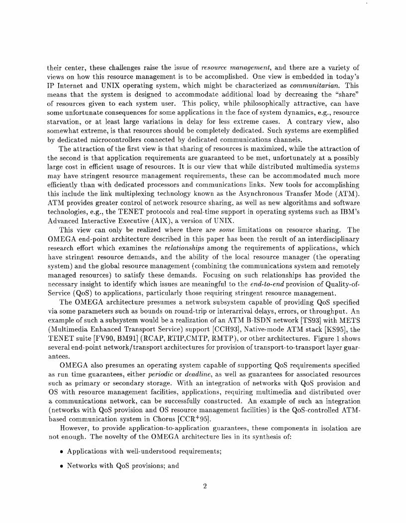
The OMEGA architecture presumes a network subsystem capable of providing QoS specified via some parameters such as bounds on round-trip or interarrival delays, errors, or throughput. An example of such a subsystem would be a realization of an ATM B-ISDN network [TS93] with METS (Multimedia Enhanced Transport Service) support [CCH93], Native-mode ATM stack [KS95], the TENET suite [FV90, BM911 (RCAP, RTIP,CMTP, RMTP), or other architectures. Figure 1 shows several end-point network/transport architectures for provision of transport-to-transport layer guar- antees.
OMEGA also presumes an operating system capable of supporting QoS requirements specified as run time guarantees, either periodic or deadline, as well as guarantees for associated resources such as primary or secondary storage. With an integration of networks with QoS provision and OS with resource management facilities, applications, requiring multimedia and distributed over a communications network, can be successfully constructed. An example of such an integration (networks with QoS provision and OS resource management facilities) is the QoS-controlled ATM- based conimunication system in Chorus [CCR+95].
However, t o provide application-to-application guarantees, these components in isolation are not enough. The novelty of the OMEGA architecture lies in its synthesis of:
Applications with well-understood requirements;
a Networks with QoS provisions; and
Operating Systems with resource management facilities;
into a system which can make robust statements about global end-to-end behavior. The system does this in a manner which provides multiple applications an approximation to their behavior when operating in a dedicated resource environment. Figure 1 shows the placement of the OMEGA architecture in comparison to other end-system architectures.
Physical Layer . . . - . . . , Transmisswn Protocols Establishment Protocols
Figure 1: End-Point Architectures Providing Guarantees according to QoS
The rest of the paper is organized as follows: in Section 2 we describe communication and resource models used for the OMEGA architecture. Section 3 briefly discusses the design of the QoS Broker (we reported on the QoS Broker protocol in [NS95b]), and concentrates on services for provision of QoS during the call establishment phase (which were illustrated in [NS95b] only by examples). In Section 4 we describe our experimental testbed, implementation, and measured results. Section 5 concludes the paper with lessons learned and suggests promising directions for future research.
2 Modeling of OMEGA Architecture
We model distributed systems as end-points connected by a network intrastructure. As indicated in the introduction, modern network infrastructures such as ATM can provide customized connections where the properties of traffic within the network are guaranteed within some limits. Applications, however, rarely interact directly with the network (e.g., with a dedicated network adapter), but rather, interact via an intervening operating system. The operating system implements a sharing policy under which processing capacity is shared between applications. The set of applications, the operating system, and the protocol stack comprise the end-points of the distributed system.
The OMEGA architecture is an end-point architecture for provision of real-time guarantees in networked multimedia systems (NMS). OMEGA achieves global application-to-application guaran- tees. We assume in this paper that network management and transmission protocols for provision of guarantees in intermediate nodes exist [PZF94, CCH93, KS951 and concentrate on the role and elements of OMEGA.
Since OMEGA functions can be partitioned into distributed and local, we model the system in two parts, (1) the communication model, and ( 2 ) the resource model at the end-points.
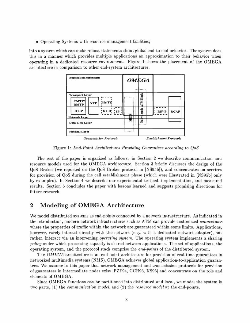
2.1 Communication Model
The communication system is modeled as a two layer system (Figure 2). The transport subsystem
Figure 2: OMEGA Communication Model
E 2 z In
3 8 .- - R
4
E I? 3 -s V1
e
t
layer includes the functionalities of the network and transport layers using Integrated Layer Pro- cessing [CT90]. Functions such as connection management, forward error correction, timing failure detection and timely data movement form the core of the Real-Time Network Protocol (RTNP).
The application subsystem layer contains the functions of the application and session layers such as call management, rate control of multimedia devices, input/output functions (e.g., display of video), fragmentation of application protocol data units (APDUs), integrationldisintegration of APDUs, etc. These functions are the core of the Real-Time Application Protocol (RTAP).
Both subsystems must provide guaranteed services over specified calls/connections for applica- tions. Therefore, they require guarantees on the resources needed for the communication. Resource guarantees are negotiated during the call establishment phase by the QoS Broker protocol [NS95b] which is an addition t o the communication architecture present in both application and transport layers, as shown in Figure 2. The broker orchestrates both local and global end-point resource availability. The protocol stack is completely schedulable; see Section 3.5.
2.2 Resource Model
w
Real-Time
Application
~rotocol (RTAP)
Real-Time
Network
Protocol (RTNP)
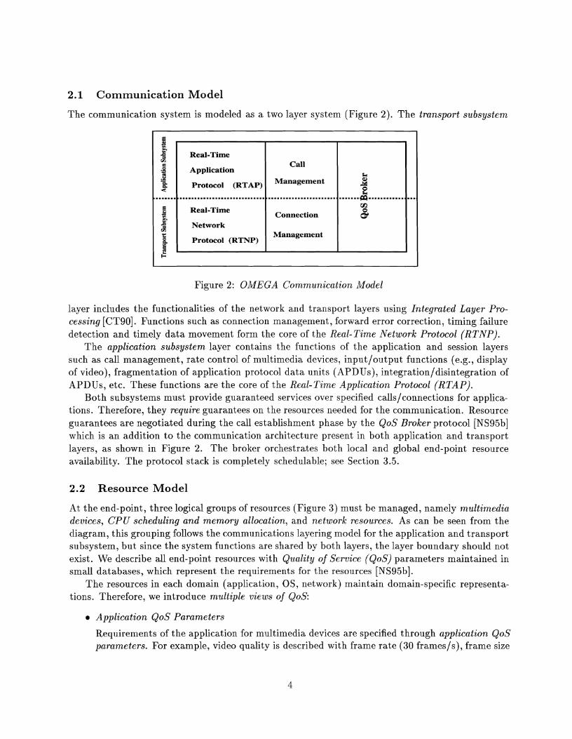
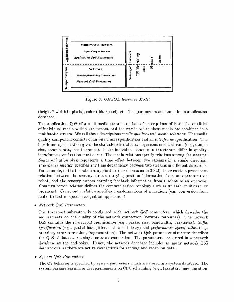
At the end-point, three logical groups of resources (Figure 3) must be managed, namely multimedia devices, CPU scheduling and memory allocation, and network resources. As can be seen from the diagram, this grouping follows the communications layering model for the application and transport subsystem, but since the system functions are shared by both layers, the layer boundary should not exist. We describe all end-point resources with Quality of Service (QoS) parameters maintained in small databases, which represent the requirements for the resources [NS95b].
The resources in each donlain (application, OS, network) maintain domain-specific representa- tions. Therefore, we introduce multiple views of QoS:
a Application QoS Parameters
Call
Management
,.......,.....................................................,.......cp............,...
Connection
Management
Requirements of the application for multimedia devices are specified through application QoS parameters. For example, video quality is described with frame rate (30 framesls), frame size
k
3 z rn 6
E
InputlOutput Devices U1
Network
SendinglReceiving Connections
H
Figure 3: OMEGA Resource Model
(height * width in pixels), color ( bits/pixel), etc. The parameters are stored in an application database.
The application QoS of a multimedia stream consists of descriptions of both the qualities of individual media within the stream, and the way in which these media are combined in a multimedia stream. We call these descriptions media qualities and media relations. The media quality component consists of an interframe specification and an intraframe specification. The interframe specification gives the characteristics of a homogeneous media stream (e.g., sample size, sample rate, loss tolerance). If tlze individual samples in the stream differ in quality, intraframe specification must occur. The media relations specify relations among the streams. Synchronization skew represents a time offset between two streams in a single direction. Precedence relation specifies any time dependency between two streams in different directions. For example, in the telerobotics application (see discussion in 3.3.2), there exists a precedence relation between the sensory stream carrying position information from an operator to a robot, and the sensory stream carrying feedback information from a robot t o an operator. Communication relation defines the communication topology such as unicast, multicast, or broadcast. Conversion relation specifies transformations of a medium (e.g. conversion from audio t o text in speech recognition application).
a Network QoS Parameters
The transport subsystem is configured with network QoS parameters, which describe the requirements on the quality of the network connection (network resources). The network QoS contains the throughput specification (e.g., packet size, bandwidth, burstiness), trafic specification (e.g., packet loss, jitter, end-to-end delay) and performance specification (e.g., ordering, error correction, fragmentation). The network QoS parameter structure describes the QoS of data over a single network connection. The parameters are stored in a network database at the end-point. Hence, the network database includes as many network QoS descriptions as there are active connections for sending and receiving data.
a System QoS Parameters
The OS behavior is specified by system parameters which are stored in a system database. The system parameters mirror the requirements on CPU scheduling (e.g., task start time, duration,
and deadline) and buffer allocation of the multiniedia stream across both subsystems.
As we explained in the introduction, resource allocation must be performed for guarantees to be made. We also noted that one of the key questions was the strictness with which resource allocation would be performed versus the potentially contrary design goal of accommodating dynamics. The point at which the allocation decisions are made in a networked system (such as those we focus on) is called "call establishment". The next section of the paper explains the new mechanisms and techniques we have developed for the end-to-end call establishment in the OMEGA architecture.
3 Call Establishment
Among the new mechanisms for the end-to-end call establishment are the QoS Broker, its underlying services and the schedulable protocol stack. A full description of the QoS Broker protocol design and implementation is presented in [NS95b]; we provide a brief overview here and concentrate on a detailed discussion of services used by the broker, which are illustrated in [NS95b] only through examples.
3.1 Design of QoS Broker
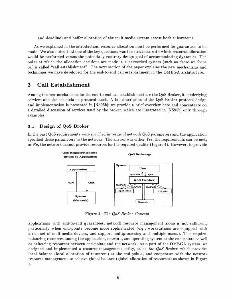
In the past QoS requirements were specified in terms of network QoS parameters and the application specified these parameters t o the network. The answer was either Yes, the requirements can be met, or No, the network cannot provide resources for the required quality (Figure 4). However, to provide
QoS RequesVResponse
driven by Application
Application 57 System
(Network)
QoS Brokerage
Figure 4: The QoS Broker Concept
System User
Q o S N m QoS
QoS Broker
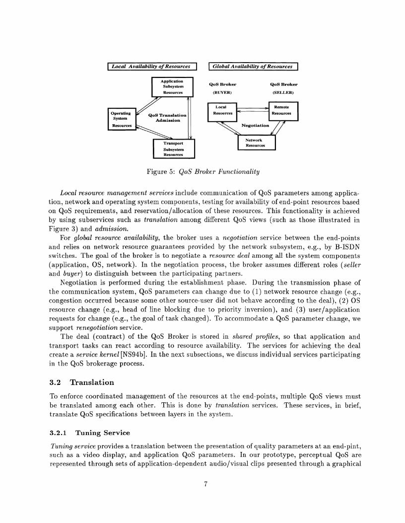
applications with end-to-end guarantees, network resource management alone is not sufficient, particularly when end-points become more sophisticated (e.g., workstations are equipped with a rich set of multimedia devices, and support multiprocessing and multiple users.). This requires balancing resources among the application, network, and operating system at the end-points as well as balancing resources between end-points and the network. As a part of the OMEGA system, we designed and implemented a resource management entity, called the QoS Broker, which provides local balance (local allocation of resources) at the end-points, and cooperates with the network resource management to achieve global balance (global allocation of resources) as shown in Figure 5.
Application CPUIOS
v Network
Application Subsystem
Resources
A
Operating QoS Translation System Admission Resources
Transport
Subsystem Resources
Local Availability of Resources
QoS Broker QoS Broker
Global Availability of Resources
(BUYER) (SELLER)
Resources Resources
Network Resources
Figure 5: QoS Broker Functionality
Local resource management services include communication of QoS parameters among applica- tion, network and operating system compoizents, testing for availability of end-point resources based on QoS requirements, and reservation/allocation of these resources. This functionality is achieved by using subservices such as translation among different QoS views (such as those illustrated in Figure 3) and admission.
For global resource availability, the broker uses a negotiation service between the end-points and relies on network resource guarantees provided by the network subsystem, e.g., by B-ISDN switches. The goal of the broker is to negotiate a resource deal among all the system components (application, OS, network). In the negotiation process, the broker assumes different roles (seller and buyer) t o distinguish between the participating partners.
Negotiation is ~erformed during the establishment phase. During the transmission phase of the conlmunication system, QoS parameters can change due to (1) network resource change (e.g., congestion occurred because some other source-user did not behave according to the deal), (2) OS resource change (e.g., head of line blocking due to priority inversion), and (3) user/application requests for change (e.g., the goal of task changed). To accommodate a QoS parameter change, we support renegotiation service.
The deal (contract) of the QoS Broker is stored in shared profiles, so that application and transport tasks can react according to resource availability. The services for achieving the deal create a service kernel [NS94b]. In the next subsections, we discuss individual services participating in the QoS brokerage process.
3.2 Translation
To enforce coordinated management of the resources at the end-points, multiple QoS views must be translated among each other. This is done by translation services. These services, in brief, translate QoS specifications between layers in the system.
3.2.1 Tuning Service
Tuning service provides a translation between the presentation of quality parameters at an end-pint, such as a video display, and application QoS parameters. In our prototype, perceptual QoS are represented through sets of application-dependent audio/visual clips presented through a graphical
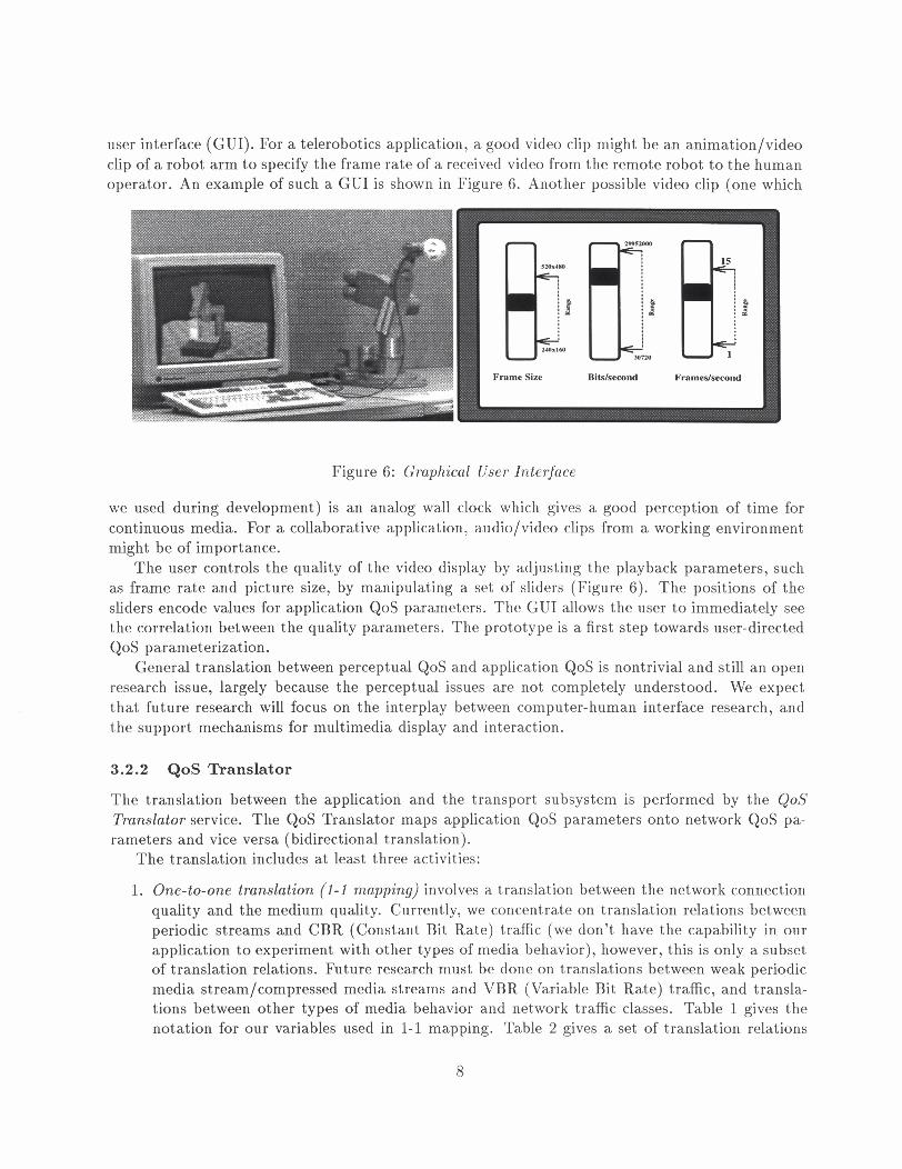
user interface (GUI). For a telerobotics application, a good video clip might be an animation/video clip of a robot arm to specify the frame rate of a received video from the remote robot to the human operator. An example of such a GUI is shown in Figure 6. Another possible video clip (one which
Frame Size BiWseeond Frames/second
Figure 6: Graphical User Interface
we used during development) is an analog wall clock which gives a good perception of time for continuous media. For a collaborative application, audio/video clips from a working environment might be of importance.
The user controls the quality of the video display by adjusting the playback parameters, such as frame rate and picture size, by manipulating a set of sliders (Figure 6). The positions of the sliders encode values for application QoS parameters. The GUI allows the user to immediately see the correlation between the quality parameters. The prototype is a first step towards user-directed QoS parameterization.
General translation between perceptual QoS and application QoS is nontrivial and still an open research issue, largely because the perceptual issues are not completely understood. We expect that future research will focus on the interplay between computer-human interface research, and the support mechanisms for multimedia display and interaction.
3.2.2 QoS Translator
The translation between the application and the transport subsystem is performed by the QoS Translator service. The QoS Translator maps application QoS parameters onto network QoS pa- rameters and vice versa (bidirectional translation).
The translation includes at least three activities:
1. One-to-one translation (1-1 mapping) involves a translation between the network connection quality and the medium quality. Currently, we concentrate on translation relations between periodic streams and CBR (Constant Bit Rate) traffic (we don't have the capability in our application to experiment with other types of media behavior), however, this is only a subset of translation relations. Future research must be done on translations between weak periodic media stream/compressed media streams and VBR (Variable Bit Rate) traffic, and transla- tions between other types of media behavior and network traffic classes. Table 1 gives the notation for our variables used in 1-1 mapping. Table 2 gives a set of translation relations

between media quality (application QoS) and throughput/traffic specification (network QoS).
Table 1: Basic Notation for Application and Network QoS (Quantitative Parameters)
Application Subsystem A Application Subsystem
(Mjl)MA (Changed) Sample Size (Rk)RA Sample Rate
PA Period between Samples (Ci )CA (Changed) End-to-End Delay LRA Sample Loss Rate IA Sample Importance
The media relations affect the performance specification as follows:
Transport Subsystem N Transport Subsystem HHD Host-to-Host Delay (M&)MN (Changed) Packet Size (Rb)RN (Changed) Packet Rate
ITN Interarrival Time between Packets PN Period between Packets (Cfv)CN (Changed) End-to-End Delay LRN Packet Loss Rate IN Packet Priority ( B k ) BN (Changed) Bandwidth
Packet Priority (IN) is inherited from the sample importance (IA).
The specification of communication (unicast/multicast/broadcast) is copied to the com- munication type.
Fragmentation is set TRUE if [MA/MN1 > 1. If fragmentation occurs, it influences the performance for CA and computation of CN. If the number of fragments is so large that CA is violated and MN is variable packet size, then MN must be changed to M h > MN
Ordering is set TRUE, if continuous media with real-time behavior are sent. In non- real-time media behavior, the ordering requirement merely depends on the application's ability t o handle out of order data.
Error Correction depends on the importance parameter ( IA) and sample loss rate (LRA) of the medium quality. If real-time behavior of the continuous media is required, its im- portance is high and sample loss rate is low, then a Forward Error Correction (FEC) [Bie93] mechanism is used in the communicatioiz protocol. Otherwise, a different er- ror correction mechanism (e.g., retransmission) can be specified, if supported by the communication protocol suite.
Cost and Burstiness mappings are currently not supported.
2. Mixing means multiplexing (at the application subsystem level) different media into a single stream which will be sent through a single network connection. This implies that the different media qualities have to be merged into a new medium quality specification (many-to-one), as shown in Figure 7. After mixing of the media qualities, a one-to-one translation occurs between resulting medium quality and the network QoS for a connection. It is important t o point out that the resulting medium quality is the union with precedence of the media qualities being integrated. Therefore, mixing should be done on media which have similar QoS requirements, otherwise a stream with unrealistic QoS requirements will result.
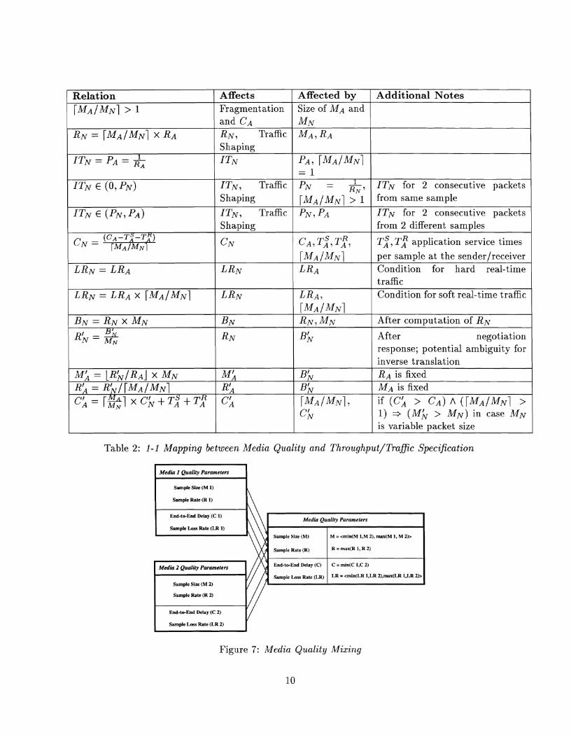
Table 2: 1-1 Mapping between Media Quality and Throughput/Trafic Specification
Media I Qaality Parameters
Relation
[ M A / M N ~ > 1
RN = [ M A / M N ~ x R A
1 ITN = PA = - R A
ITN E (0, PN)
ITN E ( P N , PA)
(C,-T~-T:) CN = T ~ A / ~ N I
LRN = LRA
LRN = LRA X [ M A / M N ~
BN = R N x MN B
R), = &
MA = LRk/RAJ x MN Ra = R & / [ M A / M N ~
- [ - ~ x c ~ + T , S + T , R C A - EN
I sample ~ i z c (M 1) L
Affected by Size of MA and MN M A , RA
PA, [ M A I M N ~ = 1
PN = RN ' [ M ~ / M ~ ~ > 1 PN,PA
CA, ~ 2 , TAR, [MA /MN1 LRA
LRA, [MA /MNl R N , M N
Bh
Bb Bh [MA / M N ~ , Ck
Affects Fragmentation and CA R N , Traffic Shaping
ITN
ITN , Traffic Shaping
I T N , Traffic Shaping
CN
LRN
LRN
BN
RN
MA RIA cjq
Samplc Rale (R 1) I\
Additional Notes
ITN for 2 consecutive packets from same sample
ITN for 2 consecutive packets from 2 different samples
~ 2 , TAR application service times
per sample at the senderlreceiver Condition for hard real-time traffic Condition for soft real-time traffic
After computation of R N
After negotiation response; potential ambiguity for inverse translation R A is fixed MA is fixed
if (cX > C A ) A ( [ M A / M N ~ > 1) + ( M A > M N ) in case MN is variable packet size
( End-trcEnd Delay (C 1) I\\ I Media Quality Paramelers I
Sample Rate (R) = I, 2, I Sample Loss Rate (LR 1)
Sample Size (MI
Figure 7: Media Quality Mising
10
M = <min(M 1,M 2), max(M 1, M 2)>
Media 2 Quality Pammeters End-tc-End Delay (C)
sample LOSS b t e (LR)
C = min(C l ,C 2)
LR = <min(LR 1,LR ZI,max(LR 1,LR 2)>
Sample Size (M 2)
Because the translation is bidirectional, ambiguities can also occur in this case. Therefore, the QoS Translator passes t o the application several possibilities and lets the applicationJuser decide which medium will suffer in quality. In a more sophisticated system, a rule-based QoS Translator can be deployed which will make decisions based on rules given by the user a priori.
3. Splitting means demultiplexing (at the application subsystem level) a medium stream into several streams which will be transmitted through several connections. This occurs when the medium stream carries different kinds of information (e.g., in a MPEG compressed video stream we have specification of I-frames, P-frames, and B-frames). Since the interframe medium quality specification includes the intraframe specification, the QoS Translator can perform one-to-one translation immediately between the intraframe component specification and the network QoS.
3.2.3 Layer-to-OS Resources Translation
Each communication layer uses OS resources; hence, a mapping between the layer QoS parameters and OS requirements is needed. We consider translations between application QoS parameters and OS resources with respect t o the application subsystem protocol (RTAP), as well as network QoS parameters and OS resources with respect to the transport subsystem protocol (RTNP). This mapping is done within the admission services.
3.3 Admission
Admission control is an essential element to achieve guaranteed services [NS95a]. For distributed multimedia communications systems, each resource along the path(s) between source(s) and sink(s) must monitor its availability.
The QoS Broker performs admission control at both layers of the OMEGA system (Figure 2). For ease of implementation, we assume networked multimedia applications with periodic media streams (e.g., uncompressed video, sensory data). The admission tests of our prototype are therefore limited to providing guarantees for this type of traffic. Aperiodic requests (tasks) may occur (e.g., QoS renegotiation/resource adaptation request), however for these requests our scheduler polls periodically and treats them as deadline-driven requests (tasks). Further, we assume that all tasks (application and network) are non-preemptive basic tasks (e.g., read sensory sample, read a video frame from a video device). The reason is that many multimedia communication systems, when testing for schedulability, assume preemptive scheduling algorithms. These algorithms assume that any message can be suspended at any time, with a small overhead, in order to transmit a higher priority message. However, in real communication systems this is rarely practical. We adapt a non- preemptive scheduling algorithm. Non-preemptive algorithms are relatively easy to implement, but the drawback is that a high priority message can be blocked by a long low priority message. This is called priority inversion [R.L94].
The applicationJnetwork QoS parameters are mapped onto the system parameters (1) task priorities, (2) task periods, and (3) buffer space requirements. The task priorities are inherited from the importance of the sample priority and equivalent to the assignment of priorities according to task deadlines (Section 3.3.1). For network tasks, the task priorities are inherited from the application tasks as discussed in Section 3.3.2. The importance of priority inheritance for support
of guarantees is clear [NS94a]. Task durations (e) as well as specification of tasks (name of the real- time protocol functions) in communication protocols are pre-computed and stored a priori in the system database. This parameter depends on the samplelpacket size. Task period (P) is computed as the inverse of the sample ratelpacket rate. The sample/packet size, fragmentation/reassembly, mixing/splitting, and error correction mechanisms determine space requirements in the system QoS (both subsystems). In our communication protocols, we allocated at least 2 x MA space for each unidirectional channel for ring buffers, so that one sample can be loaded from/to a multimedia device and another sample can be sentlreceived to/from the transport subsystem.
3.3.1 Admission Service in t h e Application Subsys tem
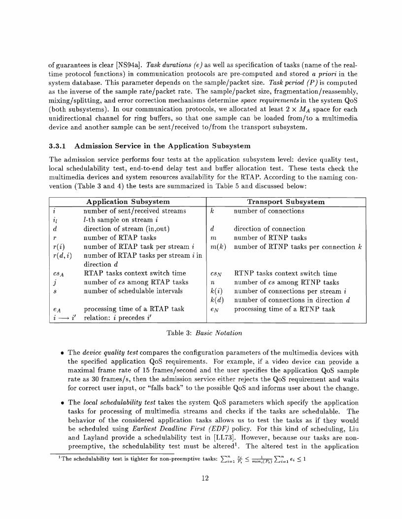
The admission service performs four tests at the application subsystem level: device quality test, local schedulability test, end-to-end delay test and buffer allocation test. These tests check the multimedia devices and system resources availability for the RTAP. According to the naming con- vention (Table 3 and 4) the tests are summarized in Table 5 and discussed below:
Table 3: Basic Notation
Application Subsys tem i number of sentlreceived streams il 1-th sample on stream i d direction of stream (in,out) r number of RTAP tasks
+I number of RTAP task per stream i
r(d, i) number of RTAP tasks per stream i in direction d
CS A RTAP tasks context switch time
j number of cs among RTAP tasks s number of schedulable intervals
e~ processing time of a RTAP task i + i' relation: i precedes i f
a The device quality test compares the configuration parameters of the multimedia devices with the specified application QoS requirements. For example, if a video device can provide a maximal frame rate of 15 frames/second and the user specifies the application QoS sample rate as 30 framesls, then the admission service either rejects the QoS requirement and waits for correct user input, or "falls back" to the possible QoS and informs user about the change.
Transpor t Subsys t em k number of connections
d direction of connection m number of RTNP tasks
m(k) number of RTNP tasks per connection k
c s ~ RTNP tasks context switch time n number of cs among RTNP tasks
k(i) number of connections per stream i
k(d) number of conilections in direction d e N processing time of a RTNP task
a The local schedulability test takes the system QoS parameters which specify the application tasks for processing of multimedia streams and checks if the tasks are schedulable. The behavior of the considered application tasks allows us to test the tasks as if they would be scheduled using Earliest Deadline First (EDF) policy. For this kind of scheduling, Liu and Layland provide a schedulability test in [LL73]. However, because our tasks are non- preemptive, the schedulability test must be altered1. The altered test in the application
'The schedulability test is tighter for non-preemptive tasks: Cy=l 2 5 ~ ~ = 1 e i 5 1
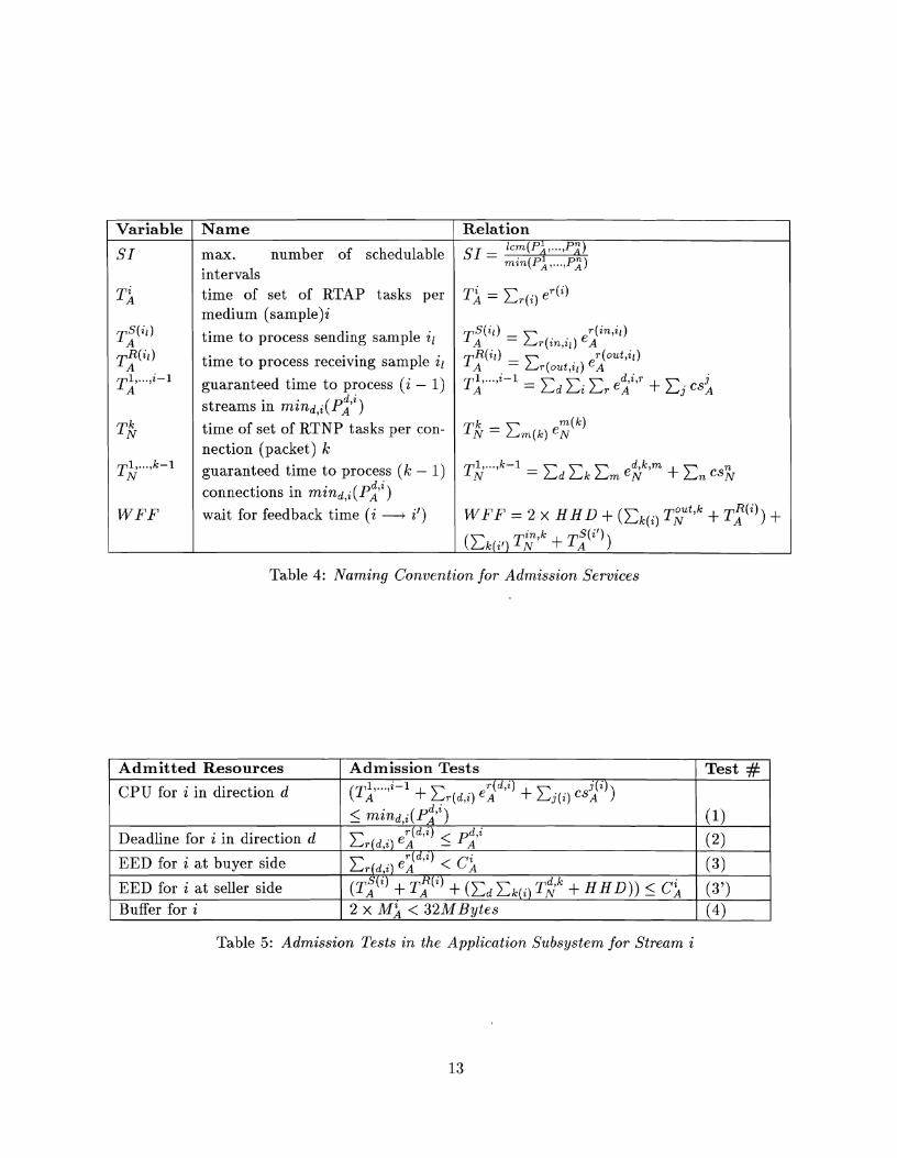
Table 4: Naming Convention for Admission Services
Relation Icm(P1 ,..., Pn)
S I = ,,,,, pil T j = XT( i ) eT(i)
~ j ( ~ ~ ) = E ~ ( ~ ~ , ~ ~ ) eA r(in, i l )
T:(") r (out,il ) = Cr(out , i i ) e~
1 , ..., i-1 T A = Ed Zi Er e i C T + C j c s i
m ( k ) T,& = eN
= Ed Em eY7" + En es%
W F F = 2 x H H D + (Ek(;) T;"~ + + (zkr;,, T E ; ' ~ + ~ 2 " " )
Variable
S I
T:
T i ( ' i ~
T;(ii)
~;l . . . .~-l
T k
W F F
Table 5: Admission Tests in the Application Subsystem for Stream i
Name
max. number of schedulable intervals time of set of RTAP tasks per medium (samp1e)i
time to process sending sample ir
time to process receiving sample ir guaranteed time to process ( i - 1) streams in mind,i(~:~)
time of set of RTNP tasks per con- nection (packet) k guaranteed time to process ( k - 1 ) connections in ~ n i n ~ , ; ( P 2 ~ ) wait for feedback time ( i + i t )
Admitted Resources
CPU for i in direction d
Deadline for i in direction d
EED for i a t buyer side
EED for i a t seller side Buffer for i
Admission Tests . .
T d , i (T~. . . I ' - ' + E,(~,;) e l ) + ~ ( i ) csa(')) 5 m i n d , i ( ~ i ' i )
d , i Cr(d,i) eYd'") PA
CT(d,i) e:"" < Ck (T:'" + T;(~) + (Ed T S k + H H D ) ) 5 C; 2 x M i < 32MBytes
Test #
(1)
( 2 )
( 3 )
(3 ' ) (4)
subsystem is the test #(I) in Table 5. Further, for each stream i in direction d, the deadline test #(2) in Table 5 holds. If the schedulability test # ( I ) cannot be met, the stream with later deadline (lower rate) will be rejected. If the schedulability test is satisfied, the task precedences are assigned according to their deadline (highest priority is assigned to the earliest deadline). If there are input and output tasks with the same period, the input tasks get higher precedence than the output tasks.
The end-to-end delay (EED) test consists of two steps. At the buyer side, the test #(3) takes the durations of the local buyer application tasks and checks them against the specified QoS EED (CA) bound. Here, we make sure that the tasks, although schedulable, don't violate the EED requirement. This is especially important in cases where PA > CA. For example, sensory data in telerobotics provide such a behavior (e.g., the task period is PAX20 ms and EED CA=10 ms).
At the seller side, all processing times of application tasks r ( i ) , network tasks m(k) over connections k(i), which carry the medium i, and the actual network latency H H D (Host-to- Host Delay) is taken into account. The test #(3') must hold.
The bufler allocation test checks if there is enough memory space for the ring buffers assigned to multimedia devices to lock them in real memory and smooth the traffic jitter. Smoothing traffic is required when measured E E D < requested E E D . Real-time networked applica- tions want the right data a t the right time (requested EED), not sooner or later (although sooner is still better than later). The ring buffers are pinned into real memory, hence Test #(4) holds in our system. The size 2 x MA is then locked in the memory. The 32 MBytes is an upper bound which can be allocated as a pinned region for user processes in the AIX 3.1 system.
3.3.2 Admission Service in the Transport Subsystem
The admission service at the transport subsystem level performs tests on network resources such as a throughput test, rate control test, network EED test, and system resources such as CPU schedulability test for RTAPIRTNP. Table 6 summarizes the admission tests in the transport subsystem.
The throughput test controls the assignment of bandwidth to individual connections. The upper bound of available aggregate throughput at the end-point is determined by the network host interface and its device driver. For example, in our system the ATM host interface (hardware) provides a transmission rate of 155 Mbps, however, the ATM transport subsystem, after overhead, provides 135 Mbps [ST93]. Hence, any throughput requested for the sending or receiving connections is checked against the 135 Mbps limit bound (Test #(6)).
The rate control test checks the number of network packets per second, moved from/to user space to/from the network host interface, against a certain bound (in our implementation, 1000). This bound results from the OS cost (due to overhead) of moving data between the user and kernel space (Test #(7)).
The end-to-end delay test checks the duration of network tasks at the end-points against the required end-to-end delay bound. The same approach as in the application subsystem with respect to buyer #(11) and seller sides #(11') must be considered here.
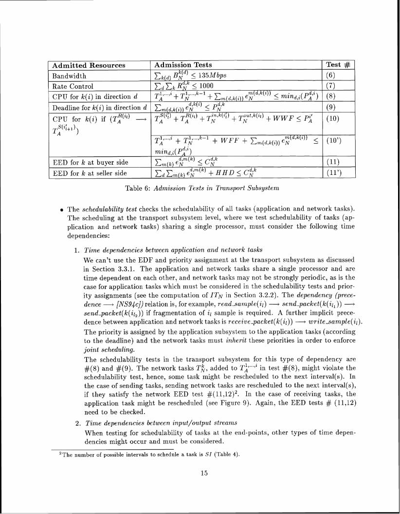
Table 6: Admission Tests in Transport Subsystem
The schedulability test checks the schedulability of all tasks (application and network tasks). The scheduling at the transport subsystem level, where we test schedulability of tasks (ap- plication and network tasks) sharing a single processor, must consider the following time
Test # (6)
(7)
(8)
(9)
(10)
(10')
(11)
(I1')
Admitted Resources
Bandwidth
Rate Control
CPU for k(i) in direction d
Deadline for k(i) in direction d
CPU for k(i) if (Tf(") - T,"'i;+l 1)
EED for k at buyer side
EED for k a t seller side
dependencies:
Admission Tests
~ 2 ~ ) 5 135Mbps
Ed Ek RY 5 1000 m(d,k(i)) , , )+ . - 1 )+ Ern ,
eN 5 mind,(^) d,k i Em(d,k(i)) en ( ) 5 P $ ~ Ti(i;; )+ T,R(ill) -I- T~ inlk(il) + T;t3klil) + WWF 5
Ti ..., " Ti ..., k-1 m ( d , k ( z ) ) )+ W F F + Crn (d ,k ( i ) ) e~ 5
m i n d , i ( ~ 2 i ) d,m k d,k Em(x) ( ) 5 C v
E~ E ~ ( ~ ) e$m(k) + HHD 5 C?
1. Time dependencies between application and network tasks We can't use the EDF and priority assignment at the transport subsystem as discussed in Section 3.3.1. The application and network tasks share a single processor and are time dependent on each other, and network tasks may not be strongly periodic, as is the case for application tasks which must be considered in the schedulability tests and prior- ity assignments (see the computation of ITN in Section 3.2.2). The dependency (prece- dence - [NS94c]) relation is, for example, read-sample(il) -+ send-packet(k(il,)) - sendqacket(k(il,)) if fragmentation of il sample is required. A further implicit prece- dence between application and network tasks is receivepacket(k(il)) - writesample(il) .
The priority is assigned by the application subsystem to the application tasks (according t o the deadline) and the network tasks must inherit these priorities in order to enforce joint scheduling. The schedulability tests in the transport subsystem for this type of dependency are #(8) and #(9). The network tasks TA, added to Ti.. '" in test #(a), might violate the schedulability test, hence, some task might be rescheduled to the next interval(s). In the case of sending tasks, sending network tasks are rescheduled t o the next interval(s), if they satisfy the network EED test #(11,12)~. In the case of receiving tasks, the application task might be rescheduled (see Figure 9). Again, the EED tests # (11,12) need to be checked.
2. Time dependencies between input/output streams When testing for schedulability of tasks at the end-points, other types of time depen- dencies might occur and must be considered.
he number of possible intervals t o schedule a task is SI (Table 4).
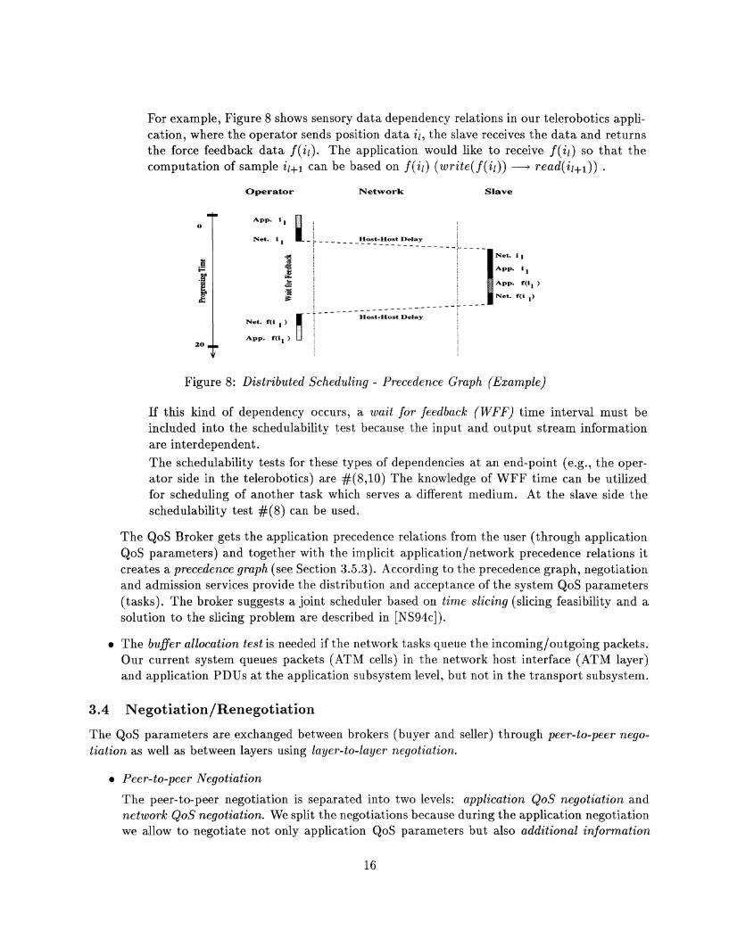
For example, Figure 8 shows sensory data dependency relations in our telerobotics appli- cation, where the operator sends position data il, the slave receives the data and returns the force feedback data f (il). The application would like to receive f (il) so that the computation of sample can be based on f (il) (write( f (il)) - .
Operator Network Slave
- * - - - - - - - - - - - - - _ _ _ _ _ - - _ - _ c - - -
Host-Host Delay
Net. i 1
App. i
APP. f(i, )
Net. f(i ,)
Figure 8: Distributed Scheduling - Precedence Graph (Example)
If this kind of dependency occurs, a wait for feedback (WFF) tinie interval must be included into the schedulability test because the input and output stream information are interdependent. The schedulability tests for these types of dependencies at an end-point (e.g., the oper- ator side in the telerobotics) are #(8,10) The knowledge of WFF time can be utilized for scheduling of another task which serves a different medium. At the slave side the schedulability test #(8) can be used.
The QoS Broker gets the application precedence relations from the user (through application QoS parameters) and together with the iniplicit application/network precedence relations it creates a precedence graph (see Section 3.5.3). According to the precedence graph, negotiation and admission services provide the distribution and acceptance of the system QoS parameters (tasks). The broker suggests a joint scheduler based on time slicing (slicing feasibility and a solution to the slicing problem are described in [NS94c]).
a The buffer allocation test is needed if the network tasks queue the incomingloutgoing packets. Our current system queues packets (ATM cells) in the network host interface (ATM layer) and application PDUs at the application subsystem level, but not in the transport subsystem.
3.4 Negotiat ion/Renegotiation
The QoS parameters are exchanged between brokers (buyer and seller) through peer-to-peer nego- tiation as well as between layers using layer-to-layer negotiation.
a Peer-to-peer Negotiation
The peer-to-peer negotiation is separated into two levels: application QoS negotiation and network QoS negotiation. We split the negotiations because during the application negotiation we allow to negotiate not only application QoS parameters but also additional information
relevant to application such as images, position, etc. This approach allows the application to negotiate application specific goals without reserving/allocating/holding shared network resources (which might be expensive).
The network negotiation of QoS exchanges negotiation messages about the traffic quality on different connections. The sender reports connection/network QoS values mappings. The remote side checks its own capabilities to provide the receiving traffic quality and reports the result to the sending subsystem. The network QoS parameters can be also changed by the network management. Hence, this negotiation is actually a three party negotiation because the network management at the switches can modify the QoS. The response is either 'accept', 'modify' or 'reject'. For 'accept'/'modify', the response is sent to the broker buyer with the possible network QoS, which means that resources are allocated. In case of 'reject' deeper analysis must occur as to what media, which connections, and what quality were rejected. For example, if robotics data and their quality is rejected, the multimedia call makes no sense, so the application has to terminate. A possible application negotiation in our implementation is described in Section 4.2.3.
Layer-to-layer Negotiation
If the negotiation at the application subsystem level succeeded, the QoS Broker initiates application-to-transport negotiation. From the view of the application it is a bidirectional negotiation, which means that application QoS parameters are forwarded (through the QoS Translator) to the trailsport subsystem, and the transport subsystem negotiates the QoS values within the subsystem and may change them. The translated application QoS values come to the buyer (initiator) application subsystem. An important part of the negotiation process is the translation of QoS parameters done by the QoS Translator as described in 3.2.2.
Renegotiation is performed during the transmission phase. The joint schedule includes a task 'renegotiation' which is scheduled once each mind,i(~i'" to read a shared variable. Here, the user/application or network can store their request for renegotiation and one possible parameter to change3. If request for change is specified, QoS Broker is invoked (now in renegotiation state) and it changes the contract. If possible, this is done as a background task.
3.5 Schedulable Protocol Stack
The protocol functions performed during the transmission phase form a set of functions configurable according to QoS requirements. The broker specifies, in the system QoS profile, which tasks (functions) are needed in the application subsystem and transport subsysten~ to meet the target guarantees for the whole system. There are two types of functions:
Basic Functions
Basic protocol functions such as sendlreceive packets and readlwrite samples must be per- formed. These functions behave according to a certain protocol among the remote protocol
3~nr ren t ly , in our implementation we allow the change of only one parameter - video frame rate. Further, we allow only the relaxation of the bound because we want to do renegotiation in real-time. If a tighter bound is specified than negotiated, the renegotiation can't be made in real-time because a new schedulability analysis must be performed. In this case, the QoS parameters must be negotiated from the beginning, i.e., the medium call/connection has to be torn down and a new connection must be established.

entities and in a local end-point protocol stack according to precedence relations between the protocol layers and between the protocol functions within a protocol layer as discussed in Section 3.3.2.
The QoS requirements have an impact on the behavior of the basic functions as follows: the samplelpacket size influences the processing duration (service time) of these functions, the number of performed basic functions, and deadline guarantees.
Optional functions
The set of optional functions is enabled or disabled according to the QoS requirements. In our protocol stack, error correction mechanism, such as Forward Error Correction (FEC), is part of the set. If video is transmitted with its soft real-time guarantees and its function as a supporting medium in a telerobotics application, FEC is disabled. On the other hand, sensory data in such an application is the primary medium with hard real-time guarantees, and therefore, the FEC mechanism is enabled by the QoS Broker.
Hence, the contract of the broker is a precedence graph of protocol functions with respect to explicit precedence relations (specified in application QoS) between protocol functions within a protocol layer and implicit precedence relations (given by the protocol stack structure) between the protocol layers t o provide global guarantees.
3.5.1 Real-Time Application Protocol Functions
Application protocol functions specify the goal of the application. We concentrate currently on a set of application protocol functions for support of real-time remote control applications, hence for another class of applications, the set of functions might be different.
The basic set of functions is : call management for uni-directional media streams, read/write of Application Protocol Data Unit (APDU) such as display images, grab data from a device, in- put/output device rate control for multimedia devices, and error detection/reporting. Optional functions are manipulations of an APDU such as fragmentation, integrationldisintegration (which depends on the size of an APDU and the similarity/dissimilarity of application QoS), and intraframe synchronization if application subsamples are specified.
3.5.2 Real-Time Network Protocol Functions
Network protocol functions provide services between the application subsystem and the network host interface. The basic services are: connection management for uni-directional connections, data movement from/to application ring buffers tolfrom network host interface, and time error detection/reporting mechanism. As an optional function, we currently support a Forward Error Correction mechanism.
3.5.3 Computation of Precedence Graph - Scheduling
The configurable protocol functions are ordered into a precedence graph and using time slicing mapped into a sequence of time slots which are executed by the scheduler in the specified order. The algorithm used is as follows:
1. register 1, . . . , i streams in direction d through application QoS
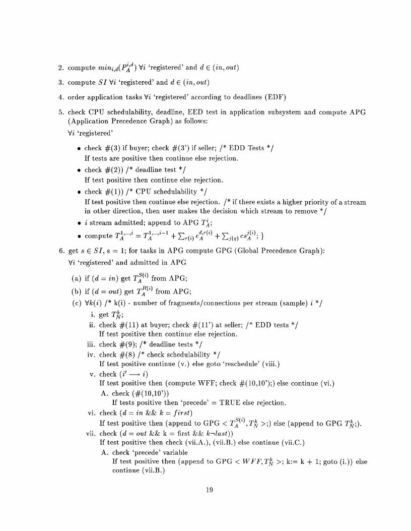
2. compute rnini,d(pjd) Vi 'registered' and d E (in, out)
3. compute SI Vi 'registered' and d E ( in , out)
4. order application tasks Vi 'registered' according to deadlines (EDF)
5 . check CPU schedulability, deadline, EED test in application subsystem and compute APG (Application Precedence Graph) as follows:
Vi 'registered'
a check #(3) if buyer; check #(3') if seller; / * EDD Tests */ If tests are positive then continue else rejection.
a check #(2)) /* deadline test */ If test positive then continue else rejection.
check #(I)) / * CPU schedulability */ If test positive then continue else rejection. / * if there exists a higher priority of a stream in other direction, then user makes the decision which stream to remove */
a i stream admitted; append to APG T i ;
6. get s E S I , s = 1; for tasks in APG compute GPG (Global Precedence Graph):
'di 'registered' and admitted in APG
(a) if (d = in) get T:(') from APG;
(b) if (d = out) get T:(" from APG;
(c) Vk(i) /* k(i) - number of fragnients/connections per stream (sample) i */ i. get T&;
ii. check #(11) at buyer; check #(11') at seller; /* EDD tests */ If test positive then continue else rejection.
iii. check #(9); /* deadline tests */ iv. check #(8) /* check schedulability * /
If test positive continue (v.) else goto 'reschedule' (viii.) v. check (it - i)
If test positive then (compute WFF; check #(10,107);) else continue (vi.) A. check (#(10,10'))
If tests positive then 'precede' = TRUE else rejection. vi. check (d = in && k = f i rs t )
If test positive then (append to GPG < T;('),T~ >;) else (append t o GPG T&;). vii. check (d = out && k = first && Ic l las t ) )
If test positive then check (vii.A.), (vii.B.) else continue (vii.C.) A. check 'precede' variable
If test positive then (append to GPG < W F F , T ~ >; k:= k $ 1; goto (i.)) else continue (vii.B .)
B. check ( 3 W F F ) A (TA < W F F ) If tests positive then (insert T$ in GPG instead of WFF;) else (append t o GPG ~ k ; k : = k + l ; goto (i.)).
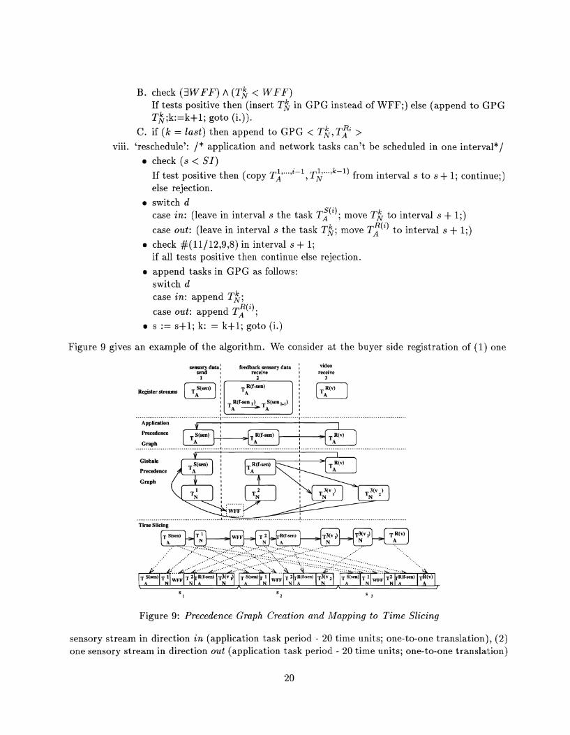
C. if (k = last) then append to GPG < TA, T? > viii. 'reschedule': / * application and network tasks can't be scheduled in one interval*/
check (s < SI) If test positive then (copy T:'".'~-~ , T ~ " " ~ - " from interval s t o s + 1; continue;) else rejection.
switch d case in: (leave in interval s the task T:"); move T& t o interval s + 1;)
case out: (leave in interval s the task Tk; move T:'" t o interval s + 1;)
check #(11/12,9,8) in interval s $ 1; if all tests positive then continue else rejection.
append tasks in GPG as follows: switch d case in: append T;;
R(i). case out: append TA , s := s+1; k: = k+l ; goto (i.)
Figure 9 gives an example of the algorithm. We consider a t the buyer side registration of (1) one
Register streams
senmm data: feedback sensory data I
recelve 1 '
I
I R(f-sen I )= TAS(~en I+,) : I
video receive
3
Figure 9: Precedence Graph Creation and Mapping to Time Slicing
sensory stream in direction in (application task period - 20 time units; one-to-one translation), (2) one sensory stream in direction out (application task period - 20 time units; one-to-one translation)

and (3) one video stream in direction out (application task period - 60 time units; one-to-one translation). The lcm is 60 time units, and the number of intervals, scheduled differently, is S I = 3. The intervals are labeled as sl, sa, s3. The tasks are labeled according to Table 3 and 4.
4 Validation of OMEGA Architecture
We validated the OMEGA architecture using a telerobotics application over high-speed ATM (Asyn- chronous Transfer Mode) LAN network. The telerobotics/teleoperation application is nontrivial and has challenges distinct from teleconferencing. This application puts new constraints on the sys- tem architecture of the end-points as well as on protocols and services in the network architecture because of the following specific properties and requirements:
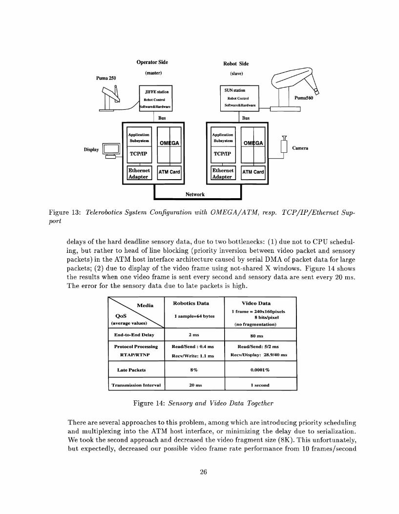
1. Telerobotics includes end-points (robots) without a human user as well as end-point with a human operator. A system configuration for a possible telerobotics environment4 is shown in Figure 13. Here, the setup of the remote (slave) side must occur remotely without help of a human operator. This setup process must be done in a robust manner.
2. The media used in our environment are sensory data, video, and optional audio. The sensory data specify the positions of the robot arm and are transmitted to the slave. The slave sends force feedback sensory data indicating the forces of the robot arm. Audio/Visual information supplements the feedback information for the operator. Based on the feedback information the operator decides5 on the next move of the master arm which then translates into position coordinates, transmitted to the slave. A closed loop exists between the master arm and the slave arm.
Audio/Visual information6 are supporting information for the operator to have audio/visual control over the working space of the remote robot, and to allow proper decisions in case of a robot failure.
3. The telerobotics requirements on the sensor data transmission are: (1) very high reliability, i.e., loss of one position in 1 minute is allowed, and no two consecutive positions can be lost; (2) the position is encoded as a vector of 12 floating point values where the elements have a varying importance for the robotics application; (3) end-to-end delay of position information must be guaranteed and the upper bound is 10 ms; (4) the positions (samples) should arrive with approximately the same interarrival time (20 ms), i.e., the sample rate of the positions is 50 samples/s; (5) sensory data are transmitted in both directions with the same quality, and (6) the precedence relation between sensory streams at the operator side is write( f (mk)) - read(mk+l).
4. The requirements on video data transmission are: (1) loss of one frame per second, (2) end- to-end delay is less than 200 ms, and (3) the frame rate is 5 frames/s.
4 ~ h i s is our current telerobotics system configuration. 'The feedback can also be used to run a simulator/planner at the operator side. The simulator determines the next
move of the master arm and hence the slave arm. The operator serves as an observer to cope with failure/disaster cases.
'The implementation currently uses only video.
4.1 Experimental Setup
An OMEGA prototype is currently running on IBM RISC System/6000 workstations under the AIX OS. The master side uses an IBM RISC System/6000 Model 530, the slave side uses an IBM RISC System/6000 Model 360. The robot control software and hardware resides two other machines: the JIFFE real-time processor (supplied to the General Robotics and Sensory Perception [GRASP] Lab by AT&T Bell Laboratories) at the master side and a SUN 4 workstation with real- time OS support for UNIX. The two RISC System/6000 workstations are connected through ATM host interfaces using G-LINK physical interface at the speed of 155 Mbits [TS93]. The RISC System/6000 workstations are connected to the individual robot control stations via cards from BIT3 Corporation which provide an S-Bus-to-MCA connection. OMEGA treats access to a robot control bus as a multimedia device access. The RISC System/6000 Model 360 includes an IBM Ultimedia video card, which can produce images at the rate of 30 frames/second.
4.2 Software Structure
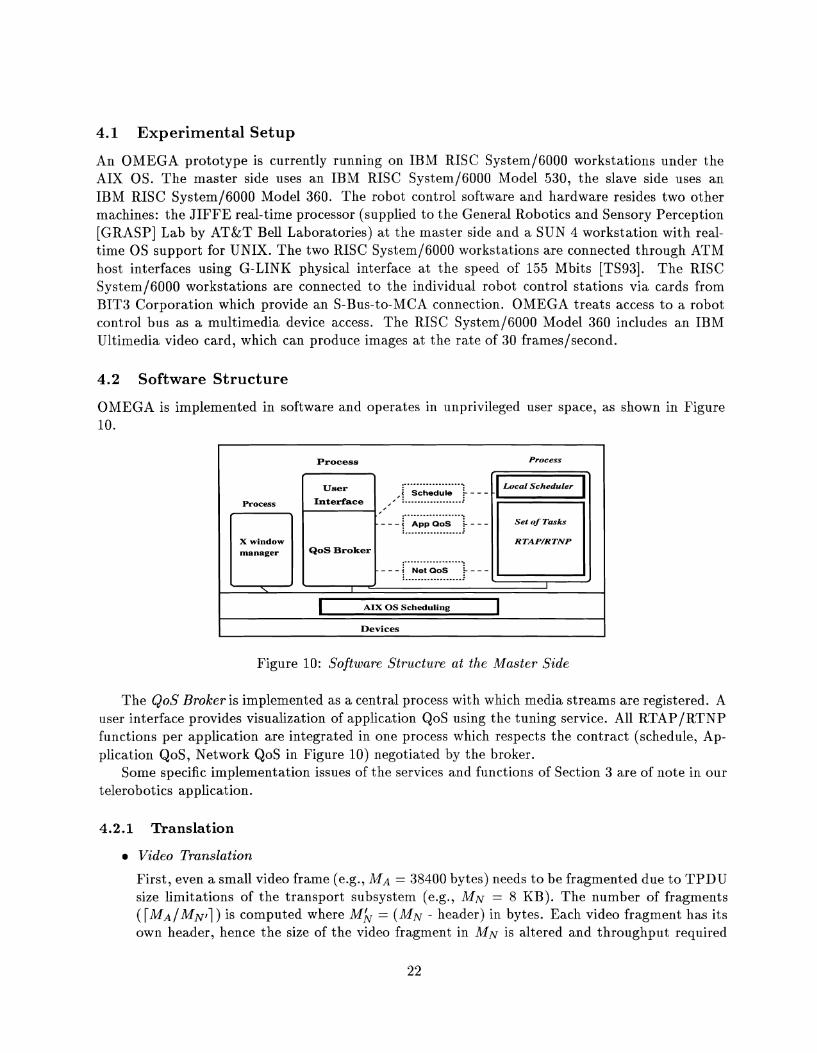
OMEGA is implemented in software and operates in unprivileged user space, as shown in Figure 10.
Figure 10: Software Structure at the Master Side
Process Process
The QoS Broker is implemented as a central process with which media streams are registered. A user interface provides visualization of application QoS using the tuning service. All RTAP/RTNP functions per application are integrated in one process which respects the contract (schedule, Ap- plication QoS, Network QoS in Figure 10) negotiated by the broker.
Some specific implementation issues of the services and functions of Section 3 are of note in our telerobotics application.
Process
X window manager
.
4.2.1 Translation
.................... User ,j Schedule t - - -
................... Interface ,, :
, '
RTAP/RTNP QoS Broker
Video Translation
\ I '
AIX OS Scheduling 1 Devices
First, even a small video frame (e.g., MA = 38400 bytes) needs to be fragmented due to TPDU size limitations of the transport subsystem (e.g., MN = 8 KB). The number of fragments ( [ M A I M N , ] ) is computed where M b = ( M N - header) in bytes. Each video fragment has its own header, hence the size of the video fragment in MN is altered and throughput required

from the network subsystem is larger than the actual MA x RA from the perspective of the application subsystem : BN = MN x [MAIM&] x RA.
Second, the loss rate of video frames, requested to be less than one framelsecond, requires the transport subsystem to detect possible lost video fragments with a window of one second. If a fragment is lost, the associated frame is presumed to be lost, and if fragments from more than one frame are lost, an exception is signaled.
Third, we may use multiple ATM virtual circuits to send the fragments over the ATM network. This makes sense when different qualities are attached to different fragments of the video frame.
a Sensor Data Translation
Sensory data consists of four components N, 0, A, P represented as a transformation matrix of floating point values:
The components have different relative importance ratings for the robotics application. The P component is the most important. Robotics data are separated in transport PDUs according to their importance.
The xp, yp, zp values and robotics header form one PDU and can be packed into one ATM cell. This PDU gets connection assignment ( VCIl) and is transported with no ATM Adap- tation Layer (AAL) support. This connection gets the highest priority in scheduling of the connections in OMEGA. The throughput for VCIl is cell size * sensor data rate + redundant information from FEC. FEC is used for VCIl due to the data's high reliability requirement.
The other data are split into three PDUs and sent over connections VC12, VC13, and VC14 with a lower priority. There is no FEC performed for these PDUs. Each PDU fits into an ATM cell, hence the throughput of data over each VCI2, VCI3, VC14 is cell size * sensory data rate. For these PDUs at the receiver (slave side) the application subsystem buffers a previous copy in case of error detection/report from the transport subsystem, and the copy can be forwarded to the application. Because of the reliability requirement from the robotics application (1 robotics packet per minute), this translates to 1 dropped PDU per VCI per minute.
4.2.2 Admission
The admission service has access to shared profiles (these are the databases we mentioned earlier in Section 3.2.). When all resources are allocated, the contract for each group of resources is stored in these profiles.
The system profile at system startup includes a priori precomputed task durations (RTAPIRTNP tasks) for each medium/connection supported in the real-time networked multimedia application. This is required for schedulability decisions. The result of the schedulability tests is a suggested
feasible schedule (precedence graph) of all tasks participating in that particular application. This schedule is stored in the system profile as the contract for CPU scheduling. These precedence graphs can be used to test possible interleavings of tasks in the system.
4.2.3 Negotiation
Application QoS negotiation is application-specific. In telerobotics, it is initiated at the operator (QoS Broker - buyer) side. It is performed out-of-band. The buyer specifies the application QoS , and additional information such as (image, position). The slave, receiving the negotiation message, (1) checks the application QoS parameters, (2) grabs a video image of the robot arm, (3) gets the initial position coordinates of the robot arm, and (4) sends a response negotiation message. The negotiation message includes (1) a response to the operator's sending QoS parameters ('accept', 'modify', or 'reject'), and (2) the video image and initial position. The operator checks the accep- tance response and if the answer is 'reject', the teleoperation between the operator and slave cannot be performed. If the answer is 'accept'/'modify', the operator allocates resources, and examines the video image as well as the position of the robot arm. The robot arm should be in the 'PARK' position. It is crucial for the operator to view the working space of the robot arm in case there are obstacles. If the working space ('robot work envelope') is free, the next negotiation message includes a request for the slave t o move the robot arm to a starting ('READY') position.
The slave moves t o the specified position after receiving the second negotiation message and responds with 'prepared' for further operations and positions.
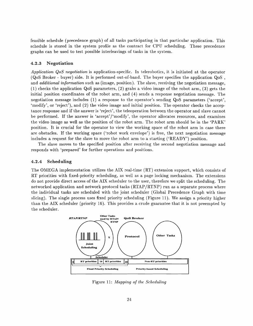
4.2.4 Scheduling
The OMEGA implementation utilizes the AIX real-time (RT) extension support, which consists of RT priorities with fixed-priority scheduling, as well as a page locking mechanism. The extensions do not provide direct access of the AIX scheduler to the user, therefore we split the scheduling. The networked application and network protocol tasks (RTAP/RTNP) run as a separate process where the individual tasks are scheduled with the joint scheduler (Global Precedence Graph with time slicing). The single process uses fixed priority scheduling (Figure 11). We assign a priority higher than the AIX scheduler (priority 16). This provides a crude guarantee that it is not preempted by the scheduler.
Other Tasks RTAP/RTNP used by RTAPI QoS
Protocol Other Tasks
RT priorities 16 RT priorities 4" Non-RT priorities I I Fixed Priority Scheduling Priority-based Scheduling
Figure 11: Mapping of the Scheduling
4.2.5 Restrictions in our Implementation
Currently, there are some significant restrictions in our implementation. First, we tested OMEGA for one user per workstation and one multimedia application (telerobotics). Second, the QoS Broker functions for interaction with network management in the ATM network are not completely implemented, as our dedicated ATM LAN does not support any signaling. However, the use of a dedicated ATM LAN allows us t o assume that network resources are always available, enabling us t o concentrate on end-point issues.
4.3 Results
QoS Broker Performance
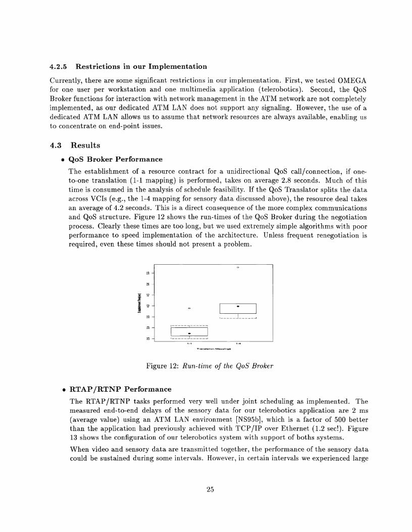
The establishment of a resource contract for a unidirectional QoS call/connection, if one- to-one translation (1-1 mapping) is performed, takes on average 2.8 seconds. Much of this time is consumed in the analysis of schedule feasibility. If the QoS Translator splits the data across VCIs (e.g., the 1-4 mapping for sensory data discussed above), the resource deal takes an average of 4.2 seconds. This is a direct consequence of the more complex communications and QoS structure. Figure 12 shows the run-times of the QoS Broker during the negotiation process. Clearly these times are too long, but we used extremely simple algorithms with poor performance to speed implementation of the architecture. Unless frequent renegotiation is required, even these times should not present a problem.
Figure 12: Run-time of the QoS Broker
RTAPIRTNP Performance
The RTAP/RTNP tasks performed very well under joint scheduling as implemented. The measured end-to-end delays of the sensory data for our telerobotics application are 2 ms (average value) using an ATM LAN environment [NS95b], which is a factor of 500 better than the application had previously achieved with TCP/IP over Ethernet (1.2 sec!). Figure 13 shows the configuration of our telerobotics system with support of boths systems.
When video and sensory data are transmitted together, the performance of the sensory data could be sustained during some intervals. However, in certain intervals we experienced large
Operator Side Robot Side
(master) Puma 250
Display
Figure 13: Telerobotics System Configuration with OMEGA/ATMj resp. TCP/IP/Ethernet Sup- port
delays of the hard deadline sensory data, due to two bottlenecks: (1) due not to CPU schedul- ing, but rather to head of line blocking (priority inversion between video packet and sensory packets) in the ATM host interface architecture caused by serial DMA of packet data for large packets; (2) due t o display of the video frame using not-shared X windows. Figure 14 shows the results when one video frame is sent every second and sensory data are sent every 20 ms. The error for the sensory data due to late packets is high.
Figure 14: Sensory and Video Data Together
There are several approaches to this problem, among which are introducing priority scheduling and multiplexing into the ATM host interface, or minimizing the delay due to serialization. We took the second approach and decreased the video fragment size (8K). This unfortunately, but expectedly, decreased our possible video frame rate performance from 10 frames/second
Video Data
1 frame = 240xl60pixels 8 bitslpixel
(no fragmentation)
SO ms
ReadISend: 512 ms
RecvlDisplay: 28.9140 ms
0.0001%
1 second
Robotics Data
1 sample-64 bytes
(average values)
End-to-End Delay
Protocol Processing
RTAPIRTNP
Late Packets
Transmission Interval
2 ms
ReadISend : 0.4 m s
RecvlWrite: 1.1 ms
8 %
20 ms
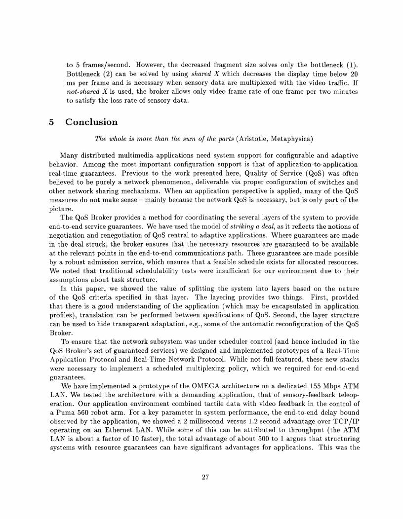
to 5 frames/second. However, the decreased fragment size solves only the bottleneck (1). Bottleneck (2) can be solved by using shared X which decreases the display time below 20 ms per frame and is necessary when sensory data are multiplexed with the video traffic. If not-shared X i s used, the broker allows only video frame rate of one frame per two minutes to satisfy the loss rate of sensory data.
5 Conclusion
The whole is more than the sum of the parts (Aristotle, Metaphysica)
Many distributed multimedia applications need system support for configurable and adaptive behavior. Among the most important configuration support is that of application-to-application real-time guarantees. Previous to the work presented here, Quality of Service (QoS) was often believed to be purely a network phenomenon, deliverable via proper configuration of switches and other network sharing mechanisms. When an application perspective is applied, many of the QoS measures do not make sense - mainly because the network QoS is necessary, but is only part of the picture.
The QoS Broker provides a method for coordinating the several layers of the system to provide end-to-end service guarantees. We have used the model of striking a deal, as it reflects the notions of negotiation and renegotiation of QoS central to adaptive applications. Where guarantees are made in the deal struck, the broker ensures that the necessary resources are guaranteed to be available at the relevant points in the end-to-end communications path. These guarantees are made possible by a robust admission service, which ensures that a feasible schedule exists for allocated resources. We noted that traditional schedulability tests were insufficient for our environment due to their assumptions about task structure.
In this paper, we showed the value of splitting the system into layers based on the nature of the QoS criteria specified in that layer. The layering provides two things. First, provided that there is a good understanding of the application (which may be encapsulated in application profiles), translation can be performed between specifications of QoS. Second, the layer structure can be used to hide transparent adaptation, e.g., some of the automatic reconfiguration of the QoS Broker.
To ensure that the network subsystem was under scheduler control (and hence included in the QoS Broker's set of guaranteed services) we designed and implemented prototypes of a Real-Time Application Protocol and Real-Time Network Protocol. While not full-featured, these new stacks were necessary to implement a scheduled multiplexing policy, which we required for end-to-end guarantees.
We have implemented a prototype of the OMEGA architecture on a dedicated 155 Mbps ATM LAN. We tested the architecture with a demanding application, that of sensory-feedback teleop- eration. Our application environment combined tactile data with video feedback in the control of a Puma 560 robot arm. For a key parameter in system performance, the end-to-end delay bound observed by the application, we showed a 2 millisecond versus 1.2 second advantage over TCP/IP operating on an Ethernet LAN. While some of this can be attributed to throughput (the ATM LAN is about a factor of 10 faster), the total advantage of about 500 to 1 argues that structuring systems with resource guarantees can have significant advantages for applications. This was the
first telerobotics application tested over A'I'M, and our roboticist colleagues are enthused about these results.
The prototype OMEGA implementation has limitations, varying between the trivially remedied and deep research questions. An exan~ple of the first is pacing required by the video service due to some bugs in the ATM interface device driver. There are many limitations from the computing and communication environment. In particular, there needs to be more control of scheduling for all elements of the computing system endpoint. This does not mean that all services must be allocated; rather, it means that the design must allow allocated services to effectively interoperate with services which can operate in a more dynaniic environment. An example system containing support of several scheduling policies such as rate-monotonic algorithm, earliest deadline first, time slicing, mixed priority scheduling, etc. is the ARTS (A Distributed Real-Time System) kernel[HT89]. Among the deepest research questions is that of mapping perceptual QoS to the kinds of algorithms and mechanisms we have discussed in this paper; we have only touched on that topic.
There are several promising directions for future work stemming from our research. First, we found that the programming of systems with time constraints was clumsy. 'l'o be more
precise, it required a mixture of application code and system code used to access timer services. This indicates a need for better support for time in programming languages. Such support might include finer divisions of Application QoS descriptions of media behavior rather than only strongly versus weakly periodic behavior, as well as refinements of the API for timing constraints and QoS. It would be desirable to specify more con~plex behaviors suc11 as:
between ( t l and t2) send da ta with QoS1;
a f t e r t2 send da t a with QoS2;
Experimental language support should be designed and prototyped, conibii~ing language support for QoS specification [FY94] and language support for time, as in Dannenberg's[Dan84] Arctic language or Lee's CSR (Communicating Shared Resources) [LDGSl] .
Second, while automatic management of resources can be managed by the operating system inferring application behavior, our observation is that current OS management policies do least well with the most complex multimedia application - those that in some sense push the edge. In making our observations above, we observed that there should be more scheduler control, as we found this particularly problematic. More generally, though, the question of application participation in resource management of all types needs examination by the operating systems community. One example of a useful step in this direction was given by Druschel, et aE.,[DPD94] who showed the value of a different perspective on buffer management as well as direct access to device resources through protected "Application Device Channels."
Finally, and extending the previous point, we think that the rebalancing of the roles of appli- cation, network and operating system should include the notion of negotiation and renegotiation. Many new systems will require adaptive behavior and we think that research should be done to identify a general kernel of functions which support this adaptation. We believe that both appli- cation adaptation to system resource changes and system adaptation to application demands must be supported.
Our OMEGA architecture provides a tested framework for flexible adaptive resource man- agement. It provides automatic translation/admission/negotiation, dynamics and guarantees to networked multimedia systems. The first successful experiments with telerobotics are encouraging,

and among our future trials will be the challenge of mobile systems based on wireless networks.
References
[Bie93] E. W . Biersack. Performance Evaluation of Forward Error Correction in an ATM Environment. IEEE JSAC, 11(4):631-640, May 1993.
[BM91] A. Banerjea and B. Mah. The Real-Time Channel Administration Protocol. In Pro- ceedings of 2nd International Workshop on Network and Operating System for Digital Audio and Video, Heidelberg, Germany, November 1991.
[CCH93] A. Campbell, G. Coulson, and D. Hutchison. A Multimedia Enhanced Transport Service in a Quality of Service Architecture. In Workshop on Network and Operating System Support for Digital Audio and Video '93, Lancaster, England, November 1993.
[CCRf 951 G. Coulson, A. Campbell, P. Robin, G. Blair, M. Papathomas, and D. Shepherd. The De- sign of a QoS-controlled ATM-Based Communications Sytem in Chorus. IEEE JSAC, 13(4):686-699, May 1995.
[CT90] D.D. Clark and D.L. Tennenhouse. Architectural Considerations for a New Generation of Protocols. In ACM SIGCOMM'90, pages 200-208, Philadelphia, PA, September 2 1990.
[Dan841 R.B. Danneberg. Arctic: A Functional Language for Real-Time Control. In ACM Symposium on LISP and Functional Programming, pages 96-103, August 1984.
[DPD94] P. Druscliel, L.L. Peterson, and B.S. Davie. Experiences with a High-Speed Net- work Adaptor. In Proceedings, 1994 SIGCOMM Conference, pages 2-13, London, UK, September 1994.
[FV90] D. Ferrari and D. C. Verma. A Scheme for Real-Time Channel Establishment in Wide- Area Networks. IEEE JSAC, 8(3):368-379, April 1990.
[FY94] P.G.S. Florissi and Y. Yemini. Managing Quality of Service in QuAL. In Proceedings of Workshop on Distributed Multimedia Applications and Quality of Service Verification, Montreal, Canada, June 1994.
[HT89] C. W. Mercer H. Tokuda. ARTS: A Distributed Real-Time Kernel. ACM Press, Oper- ating Systems Review, 23(3):29-53, July 1989.
[KS95] S. Keshav and H. Saran. Semantics and Implementation of a Native-Mode ATM Proto- col Stack. Internal technical memo, AT&T Bell Laboratories, Murray Hill, N J , January 1995.
[LDG91] I. Lee, S. Davidson, and R. Gerber. Communicating Shared Resources: A Paradigm for Integrating Real-T ime Specification and Implementation. In A.M. van Tilborg and G.M. Koob, editors, Foundations of Real-Time Computing: Formal Specifications an d Methods, pages 87-109. Kluwer Academic Press, 1991.
C. L. Liu and J. W. Layland. Scheduling Algorithms for Multiprogramming in a Hard Real-Time Environment. Journal of the ACM, 20(1):46-61, January 1973.
K. Nahrstedt and J. Smith. Experimental Study of End-to-End QoS. Technical Report MS-CIS-94-08, University of Pennsylvania, Philadelphia, PA, February 1994 1994.
K. Nahrstedt and J . Smith. A Service Kernel for Multimedia Endstations. In IWACA '94 Multimedia: Advanced Teleservices and High-Speed Communication Architectures, pages 8-22, Heidelberg, Germany, September 1994.
M. Di Natale and J. A. Stankovic. Dynamic End-to-End Guarantees in Distributed Real-Time Systems. In Proceedings Real-Time Systems Symposium, pages 216-227, December 1994.
K. Nahrstedt and J. Smith. End-Point Resource Admission Control for Remote Control Multimedia Applications. Technical Report TR-95-18, CIS, University of Pennsylvania, Philadelphia, PA, April 1995.
K. Nahrstedt and J . M. Sniith. The QoS Broker. IEEE Multimedia, 2(1):53-67, Spring 1995.
C. Parris, H. Zhang, and D. Ferrari. Dynamic Management of Guaranteed Performance Multimedia Connections. Multimedia Systems, 1(6), 1994.
R.L.R Carmo et al. Real-Time communication Services in a DQDB Network. In Proceed- ings Real-Time Systems Symposium, pages 249 -258, San Juan, Puerto Rico, December 1994.
J . M. Smith and C. Brendan S. Traw. Giving Applications Access t o Gbit/s Networking. IEEE Network, pages 44-52, July 1993.
C. B. S. Traw and J. M. Smith. Hardwarelsoftware Organization of a High-Performance ATM Host Interface. IEEE JSAC, Special Issue on High-Speed Computer/Network Interfaces, 11(2):240-253, February 1993.


![TECHNOLOGY EXPERIENCES & IMPLEMENTATION …...SMBs into the Digital Economy pg 18 [PAGE 22] [COVER STORY] TECHNOLOGY EXPERIENCES & IMPLEMENTATION ARE THE FUTURE OF RETAIL Cover Retail](https://img.pdfslide.us/doc/110x75/5f03a3f67e708231d40a0c6a/technology-experiences-implementation-smbs-into-the-digital-economy-pg.jpg)