Embed Size (px)
Citation preview
Seediscussions,stats,andauthorprofilesforthispublicationat:http://www.researchgate.net/publication/280622521
DesignGuidelinesforaWearableRoboticExtra–Finger
CONFERENCEPAPER·SEPTEMBER2015
READS
25
4AUTHORS,INCLUDING:
GionataSalvietti
IstitutoItalianodiTecnologia
24PUBLICATIONS80CITATIONS
SEEPROFILE
MonicaMalvezzi
UniversitàdegliStudidiSiena
87PUBLICATIONS665CITATIONS
SEEPROFILE
DomenicoPrattichizzo
UniversitàdegliStudidiSiena+IstitutoItalia…
292PUBLICATIONS2,872CITATIONS
SEEPROFILE
Availablefrom:GionataSalvietti
Retrievedon:05October2015
Design Guidelines for a Wearable Robotic Extra–Finger
Irfan Hussain1, Gionata Salvietti1,2, Monica Malvezzi1 and Domenico Prattichizzo1,2
Abstract— Wearable robotics is strongly oriented to humans.
New applications for wearable robots are encouraged by the
lightness and portability of new devices and the progress in
human-robot cooperation strategies. In this paper, we propose
the different design guidelines to realize a robotic extra-
finger for human grasping enhancement. Such guidelines were
followed for the realization of three prototypes obtained using
rapid prototyping techniques, i.e., a 3D printer and an open
hardware development platform. Both fully actuated and under-
actuated solutions have been explored. In the proposed wearable
design, the robotic extra-finger can be worn as a bracelet in
its rest position. The availability of a supplementary finger in
the human hand allows to enlarge its workspace, improving
grasping and manipulation capabilities. This preliminary work
is a first step towards the development of robotic extra-limbs
able to increase human workspace and dexterity.
I. INTRODUCTION
Wearable robotic structures have been mainly used insubstitution of lost limbs (e.g., prosthetic limbs) or forhuman limb rehabilitation (e.g., exoskeletons). However, theprogress in miniaturization and efficiency of the techno-logical components is allowing more and more light andcompact solutions, enhancing user’s safety and comfort [1]while opening new opportunities for wearable robot uses. Avery promising research direction is to add robotic limbs tohuman, rather than substituting or enhancing them. This ad-dition could let the human augment their abilities and couldgive support in everyday tasks. In [2], the authors presentedthe Supernumerary Robotic Limbs (SRL), a wearable robotdesigned to assist human with additional arms attached to thewearer’s body. Such devices, further investigated in [3] and[4] can closely cooperate with the human, holding an object,lifting a weight, positioning a work piece, etc.. However,finding a trade-off between wearability, efficiency and us-ability of those bulky extra-arms represents still a challenge.In our opinion, the integration with the human body shouldbe of primary importance in developing wearable devices.For that reason, we decide to investigate how to augmentthe capabilities of the human hand, instead of developingadditional arms. Focusing on the human hand, we presentedin [5], the Sixth-Finger prototype, showing how this wearabledevice is able to enhance grasping capabilities and handdexterity. In [6], we presented an object-based mappingalgorithm to control robotic extra-limbs without requiringexplicit commands by the user. A similar device has beenpresented by Wu and Asada in [7], where a 4 Degrees of
1Universita degli Studi di Siena, Dipartimento di Ingegneriadell’Informazione, Via Roma 56, 53100 Siena, Italy. {hussain,malvezzi, prattichizzo}@dii.unisi.it
2Department of Advanced Robotics, Istituto Italiano di Tecnologia, ViaMorego 30, 16163 Genoa, Italy. [email protected]
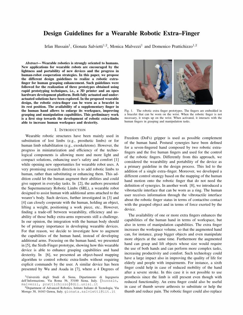
Fig. 1. The robotic extra finger prototypes. The fingers are embedded ina bracelet that can be worn on the wrist. When the robotic finger is notnecessary, it wraps up on the wrist. When activated, it interacts with thehuman fingers in grasping and manipulation tasks.
Freedom (DoFs) gripper is used as possible complementof the human hand. Postural synergies have been definedfor a seven-fingered hand composed by two robotic extra-fingers and the five human fingers and used for the controlof the robotic fingers. Differently from this approach, weconsidered the wearability and portability of the device asa primary guideline in the design process. This led to theaddition of a single extra–finger. Moreover, we developed adifferent control strategy based on the mapping of the humanhand motion onto the robotic finger that do not need thedefinition of synergies. In another work [8], we introduced avibrotactile interface that can be worn as a ring. The humanuser receives information through the vibrotactile interfaceabout the robotic finger status in terms of contact/no contactwith the grasped object and in terms of force exerted by thedevice.
The availability of one or more extra fingers enhances thecapabilities of the human hand in terms of workspace, butalso in terms of manipulation capabilities. The extra fingerincreases the workspace volume, so that the augmented handcan, for instance, grasp bigger objects and even manipulatemore objects at the same time. Furthermore the augmentedhand can grasp and lift objects whose size would requirethe use of both hands and can perform more complex tasks,increasing productivity and comfort. Such technology couldhave a large impact also in improving the quality of life forelderly and people with impairments. For instance, a sixthfinger could help in case of reduced mobility of the handafter a severe stroke. In this case it is not possible to useprosthesis since the limb is still present even though withreduced functionality. An extra finger could also be usefulin case of thumb severe arthrosis to substitute or help thethumb and reduce pain. The robotic finger could also replace
the real in case of finger amputation.In this paper, we describe both fully actuated and under-
actuated solutions for the robotic extra finger. The corre-sponding prototypes can be realized by using standard rapidprototyping techniques (see Fig.1). Both the solutions sharethe idea of wearability. The devices can be worn as braceletwhen they are not activated, and can pop up when needed.
The rest of the paper is organized as it follows. Section IIillustrates the control framework for a robotic extra-finger. InSection III the design guidelines for robotic extra-fingers aredetailed. Section III-A describes the fully actuated finger,while in Section III-B the underactuated version of thefinger is shown. Finally in Section IV experiments with theprototype of the extra-fingers are presented and in Section Vconclusion and future work are outlined.
II. HIGH LEVEL CONTROL OF EXTRA-FINGERS
The integration of the motion of the extra-fingers withthe human hand represents a critical aspect of these devices,together with the design issues related to portability andwearability. In fact, demonstration-based algorithms as thatpresented in [4] fail in generality and adaptability to newtasks. In [6], we proposed a mapping algorithm able totransfer to an arbitrary number of the robotic extra-fingersthe motion of the human hand. In this section, we recall theprinciples of the mapping procedure. The algorithm is basedon the definition of a set of reference points on the so calledaugmented hand, which includes the human hand and therobotic extra-fingers and on the definition of a virtual objectbuilt as a function of the reference points.
Let us indicate with p
hi 2 <3, i = 1, ..., nh the coordinates
of reference points on the reference human hand, expressedw.r.t. a reference frame ⌃0 defined on the hand. Although themapping proposed in [9] is general and does not require anyconstraints in the choice of the reference point number andposition, in this paper we choose the five fingertips of thehuman hand. We assume that the position of such referencepoints can be measured or evaluated, for instance by meansof an instrumented glove. Also on the artificial fingers thereference points are placed at the tip. The reference pointsfor the augmented hand are then p
ai 2 <3, i = 1, · · · , na,
with na > nh. We assume as virtual object the minimumbounding sphere S containing the reference points on theaugmented hand [9]. Let oh and r
h indicate its center andits radius respectively. Let us define a reference frame ⌃1 onthe virtual sphere, whose origin is in the sphere center andwhose axes are, in the reference starting position, parallel to⌃0 axes.
When the human hand fingers are moved, the referencepoint coordinates p
hi change, let us indicate with �p
hi 2 <3,
i = 1, · · · , nh a vector containing such coordinate variations.Such displacement produces a transformation in the virtualsphere, which can be approximated as the combination ofa rigid body motion and an isotropic deformation. Therigid body motion can be furthermore represented as thecombination of a translation �o
h 2 <3 and a rotation�� 2 <3.
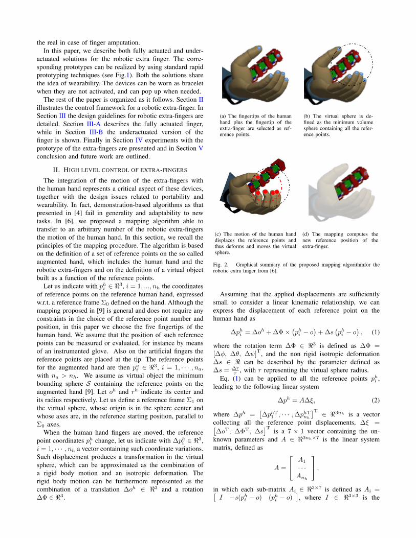
(a) The fingertips of the humanhand plus the fingertip of theextra-finger are selected as ref-erence points.
(b) The virtual sphere is de-fined as the minimum volumesphere containing all the refer-ence points.
(c) The motion of the human handdisplaces the reference points andthus deforms and moves the virtualsphere.
(d) The mapping computes thenew reference position of theextra-finger.
Fig. 2. Graphical summary of the proposed mapping algorithmfor therobotic extra finger from [6].
Assuming that the applied displacements are sufficientlysmall to consider a linear kinematic relationship, we canexpress the displacement of each reference point on thehuman hand as
�p
hi = �o
h +��⇥�p
hi � o
�+�s
�p
hi � o
�, (1)
where the rotation term �� 2 <3 is defined as �� =[��, �✓, � ]T, and the non rigid isotropic deformation�s 2 < can be described by the parameter defined as�s = �r
r , with r representing the virtual sphere radius.Eq. (1) can be applied to all the reference points p
hi ,
leading to the following linear system
�p
h = A�⇠, (2)
where �p
h =⇥�p
hT1 , · · · ,�p
hTnh
⇤T 2 <3nh is a vectorcollecting all the reference point displacements, �⇠ =⇥�o
T, ��T
, �s
⇤T is a 7 ⇥ 1 vector containing the un-known parameters and A 2 <3nh⇥7 is the linear systemmatrix, defined as
A =
2
4A1
· · ·Anh
3
5,
in which each sub-matrix Ai 2 <3⇥7 is defined as Ai =⇥I �s(phi � o) (phi � o)
⇤, where I 2 <3⇥3 is the
identity matrix and s() the skew operator. The linear systemin eq. (2) can be solved to find
�⇠ = A
+�p
h +NA , (3)
where A
+ denotes a generic pseudo–inverse of A matrix,while NA 2 <7⇥h represents a basis of A matrix nullspace,whose dimension is h � 0, and is an arbitrary h–dimensional vector parametrizing the homogeneous solutionof the system. When h > 0, the vector can be defined tooptimize a cost function that can be selected on the basisof the task. The same transformation of the sphere can beprojected on the reference points of the robotic fingers, i.e,8pai , nh < i na
�p
ai = �o
h +��⇥ (pai � o) +�r (pai � o) . (4)
Let �p
a =⇥�p
aTnh+1, · · · ,�p
aTna
⇤T be a 3(na � nh)–dimensional vector containing the reference point displace-ments on the artificial fingers. The joints of the artificialfingers are finally controlled to obtain on the fingertips thedisplacement evaluated in eq. (4). Let nq indicate the numberof joints of the artificial fingers and let Ja 2 <3(na�nh)⇥nq
indicate their Jacobian matrix [10], we can evaluate fingerjoint displacements as
�qa = J
+a �p
ai +NJ�, (5)
where J
+a denotes a generic pseudoinverse of artificial fin-
gers’ Jacobian matrix, NJ 2 <nq⇥n� is a matrix whosecolumns form a basis of Ja, n� represents the dimensionof artificial finger redundancy space, n� � 0, and finally� 2 <n� is a n�–dimensional parameter parametrizingthe homogeneous part of the solution, which represents theredundant motions of the artificial fingers. The mappingprocedure is schematically represented in Figure 2.
The procedure described above allows to move the extra-fingers according to the human hand motions without re-quiring explicit command by the user. We believe this isa key-point in the integration of external limbs in humanactivities.
III. DESIGN GUIDELINES FOR ROBOTIC EXTRA-FINGERS
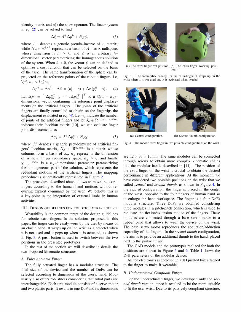
Wearability is the common target of the design guidelinesfor robotic extra fingers. In the solutions proposed in thispaper, the finger can be easily worn by the user by means ofan elastic band. It wraps up on the wrist as a bracelet whenit is not used and it pops-up when it is actuated, as shownin Fig. 3. A push button is used to switch between the twopositions in the presented prototypes.
In the rest of the section we will describe in details thetwo proposed kinematic structures.
A. Fully Actuated FingerThe fully actuated finger has a modular structure. The
final size of the device and the number of DoFs can beselected according to dimension of the user’s hand. Mod-ularity also offers robustness considering that robot parts areinterchangeable. Each unit module consists of a servo motorand two plastic parts. It results in one DoF and its dimensions
(a) The extra-finger rest position. (b) The extra-finger working posi-tion.
Fig. 3. The wearability concept for the extra-finger: it wraps up on thewrist when it is not used and it is activated when needed.
(a) Central configuration. (b) Second thumb configuration.
Fig. 4. The robotic extra finger in two possible configurations on the wrist.
are 42 ⇥ 33 ⇥ 16mm. The same modules can be connectedthrough screws to obtain more complex kinematic chainslike the modular hands described in [11]. The position ofthe extra-finger on the wrist is crucial to obtain the desiredperformance in different applications. At the moment, wehave considered two possible positions on the wrist that wecalled central and second thumb, as shown in Figure 4. Inthe central configuration, the finger is placed in the centerof the wrist, opposite to the four fingers of human hand soto enlarge the hand workspace. The finger is a four DoFsmodular structure. Three DoFs are obtained consideringthree modules in a pitch-pitch connection, which is used toreplicate the flexion/extension motion of the fingers. Thesemodules are connected through a base servo motor to arubber band that allows to wear the device on the wrist.The base servo motor reproduces the abduction/adductioncapability of the fingers. In the second thumb configuration,the aim is to provide an additional thumb to the hand, placednext to the pinkie finger.
The CAD models and the prototypes realized for both thepositions are shown in Figure 5 and 6. Table I shows theD-H parameters of the modular device.
All the electronics is enclosed in a 3D printed box attachedto the finger to make it wearable.
B. Underactuated Compliant Finger
For the underactuated finger, we developed only the sec-ond thumb version, since it resulted to be the more suitableto fit the user wrist. Due to its passively compliant structure,
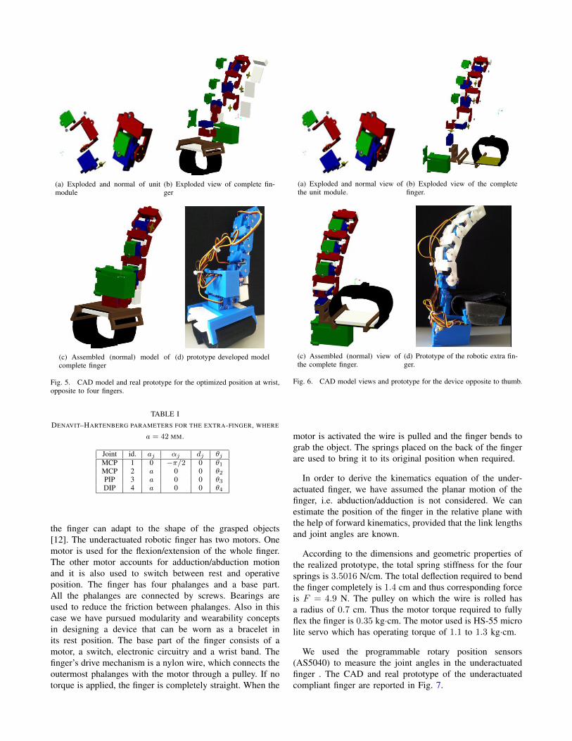
(a) Exploded and normal of unitmodule
(b) Exploded view of complete fin-ger
(c) Assembled (normal) model ofcomplete finger
(d) prototype developed model
Fig. 5. CAD model and real prototype for the optimized position at wrist,opposite to four fingers.
TABLE IDENAVIT–HARTENBERG PARAMETERS FOR THE EXTRA-FINGER, WHERE
a = 42 MM.
Joint id. aj ↵j dj ✓jMCP 1 0 �⇡/2 0 ✓1MCP 2 a 0 0 ✓2PIP 3 a 0 0 ✓3DIP 4 a 0 0 ✓4
the finger can adapt to the shape of the grasped objects[12]. The underactuated robotic finger has two motors. Onemotor is used for the flexion/extension of the whole finger.The other motor accounts for adduction/abduction motionand it is also used to switch between rest and operativeposition. The finger has four phalanges and a base part.All the phalanges are connected by screws. Bearings areused to reduce the friction between phalanges. Also in thiscase we have pursued modularity and wearability conceptsin designing a device that can be worn as a bracelet inits rest position. The base part of the finger consists of amotor, a switch, electronic circuitry and a wrist band. Thefinger’s drive mechanism is a nylon wire, which connects theoutermost phalanges with the motor through a pulley. If notorque is applied, the finger is completely straight. When the
(a) Exploded and normal view ofthe unit module.
(b) Exploded view of the completefinger.
(c) Assembled (normal) view ofthe complete finger.
(d) Prototype of the robotic extra fin-ger.
Fig. 6. CAD model views and prototype for the device opposite to thumb.
motor is activated the wire is pulled and the finger bends tograb the object. The springs placed on the back of the fingerare used to bring it to its original position when required.
In order to derive the kinematics equation of the under-actuated finger, we have assumed the planar motion of thefinger, i.e. abduction/adduction is not considered. We canestimate the position of the finger in the relative plane withthe help of forward kinematics, provided that the link lengthsand joint angles are known.
According to the dimensions and geometric properties ofthe realized prototype, the total spring stiffness for the foursprings is 3.5016 N/cm. The total deflection required to bendthe finger completely is 1.4 cm and thus corresponding forceis F = 4.9 N. The pulley on which the wire is rolled hasa radius of 0.7 cm. Thus the motor torque required to fullyflex the finger is 0.35 kg·cm. The motor used is HS-55 microlite servo which has operating torque of 1.1 to 1.3 kg·cm.
We used the programmable rotary position sensors(AS5040) to measure the joint angles in the underactuatedfinger . The CAD and real prototype of the underactuatedcompliant finger are reported in Fig. 7.
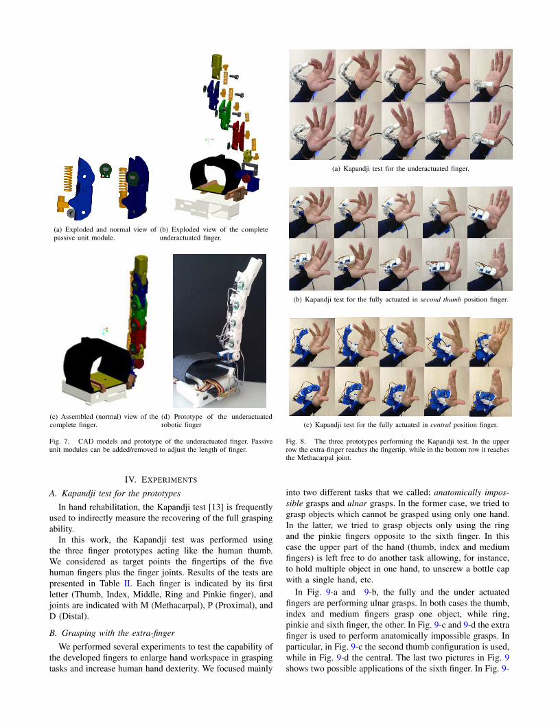
(a) Exploded and normal view ofpassive unit module.
(b) Exploded view of the completeunderactuated finger.
(c) Assembled (normal) view of thecomplete finger.
(d) Prototype of the underactuatedrobotic finger
Fig. 7. CAD models and prototype of the underactuated finger. Passiveunit modules can be added/removed to adjust the length of finger.
IV. EXPERIMENTS
A. Kapandji test for the prototypesIn hand rehabilitation, the Kapandji test [13] is frequently
used to indirectly measure the recovering of the full graspingability.
In this work, the Kapandji test was performed usingthe three finger prototypes acting like the human thumb.We considered as target points the fingertips of the fivehuman fingers plus the finger joints. Results of the tests arepresented in Table II. Each finger is indicated by its firstletter (Thumb, Index, Middle, Ring and Pinkie finger), andjoints are indicated with M (Methacarpal), P (Proximal), andD (Distal).
B. Grasping with the extra-fingerWe performed several experiments to test the capability of
the developed fingers to enlarge hand workspace in graspingtasks and increase human hand dexterity. We focused mainly
(a) Kapandji test for the underactuated finger.
(b) Kapandji test for the fully actuated in second thumb position finger.
(c) Kapandji test for the fully actuated in central position finger.
Fig. 8. The three prototypes performing the Kapandji test. In the upperrow the extra-finger reaches the fingertip, while in the bottom row it reachesthe Methacarpal joint.
into two different tasks that we called: anatomically impos-sible grasps and ulnar grasps. In the former case, we tried tograsp objects which cannot be grasped using only one hand.In the latter, we tried to grasp objects only using the ringand the pinkie fingers opposite to the sixth finger. In thiscase the upper part of the hand (thumb, index and mediumfingers) is left free to do another task allowing, for instance,to hold multiple object in one hand, to unscrew a bottle capwith a single hand, etc.
In Fig. 9-a and 9-b, the fully and the under actuatedfingers are performing ulnar grasps. In both cases the thumb,index and medium fingers grasp one object, while ring,pinkie and sixth finger, the other. In Fig. 9-c and 9-d the extrafinger is used to perform anatomically impossible grasps. Inparticular, in Fig. 9-c the second thumb configuration is used,while in Fig. 9-d the central. The last two pictures in Fig. 9shows two possible applications of the sixth finger. In Fig. 9-

TABLE IIRESULTS OF THE KAPANDJI TEST FOR THE THREE PROTOTYPES
Central Second Thumb UnderactuatedT-D X X XT-P X X XT-M X X XI-D X X XI-P X X XI-M X X XM-D X X XM-P X X XM-M X X XR-D X X XR-P X X XR-M X X XP-D X X XP-P X X XP-M X X X
e the user can unscrew a cap from a bottle using only onehand. Ulnar grasp is used to keep firm the bottle, while theother fingers can unscrew the cap. Finally, in Fig. 9-f thefully actuated finger in the central configuration is used toopen a door. The user is holding an heavy bag so cannot openthe door with the same hand. He/she uses the extra finger toturn the handle, while keeping the bag with the hand.
In all the experiments, the joint reference angles of theextra-finger are related to the human hand posture. To trackthe human hand, we used the Cyberglove III System [14].
V. CONCLUSION
In this paper we presented design guidelines and proto-type development of robotic-extra fingers for human handenhancement. A fully and an under actuated fingers aredesigned and their prototypes are realized by using 3Dprinter and open source arduino platform. The fingers arecustomized for different positions on the wrist and can beworn by a rubber band. This solution allows to enlarge thehand workspace, increasing the grasp capability of the user.
The control signals are computed without requiring ex-plicit commands by the human user, but interpreting humanhand motion.
We provided several experiments to prove the usabilityof the extra fingers. The underactuated finger resulted tobe more light and portable than the other. The passivecompliance of the finger allowed to adapt more easily tothe shape of the grasped object. On the other side, the fullyactuated version resulted to be more precise in following thehigh level control inputs and more powerful in terms of grasptightness.
We are currently improving the design and wearability ofthe robotic device. Even if the study of extra limbs is inits preliminary phase, the results showed the feasibility andthe usability of these type of devices. We believe that thesesimple and cost effective devices could have a great impactin understanding the effectiveness of robotic extra-fingers inaugmenting human hand through wearable robotics.
(a) Grasping multiple objects inone hand: fully actuated finger insecond thumb configuration
(b) Grasping multiple objectsin one hand: underactuated fin-ger
(c) Grasping box: fully actu-ated finger in second thumbconfiguration
(d) Grasping a toolbox: fullyactuated finger in central con-figuration
(e) Opening bottle with onehand: underactuated figer
(f) Opening the door, whilekeeping a bag: fully actuatedfinger in central configuration
Fig. 9. Different tasks performed with the aid of robotic-extra fingers.
ACKNOWLEDGMENT
The research leading to these results has received fundingfrom the European Union Seventh Framework ProgrammeFP7/2007-2013 under grant agreement n 601165 of theproject WEARHAP WEARable HAPtics for humans androbots.
REFERENCES
[1] J. Arata, K. Ohmoto, R. Gassert, O. Lambercy, H. Fujimoto, andI. Wada, “A new hand exoskeleton device for rehabilitation using athree-layered sliding spring mechanism,” in Robotics and Automation(ICRA), 2013 IEEE International Conference on, pp. 3902–3907, May2013.
[2] C. Davenport, F. Parietti, and H. H. Asada, “Design and biomechanicalanalysis of supernumerary robotic limbs,” in ASME 2012 5th AnnualDynamic Systems and Control Conference joint with the JSME 201211th Motion and Vibration Conference, pp. 787–793, 2012.
[3] F. Parietti and H. H. Asada, “Dynamic analysis and state estimationfor wearable robotic limbs subject to human-induced disturbances,” inIEEE International Conference on Robotics and Automation (ICRA),pp. 3880–3887, IEEE, 2013.
[4] B. Llorens-Bonilla, F. Parietti, and H. H. Asada, “Demonstration-basedcontrol of supernumerary robotic limbs,” in IEEE/RSJ InternationalConference on Intelligent Robots and Systems (IROS), pp. 3936–3942,IEEE, 2012.
[5] D. Prattichizzo, M. Malvezzi, I. Hussain, and G. Salvietti, “The sixth-finger: a modular extra-finger to enhance human hand capabilities,” inProc. IEEE Int. Symp. in Robot and Human Interactive Communica-tion, (Edinburgh, United Kingdom), 2014.
[6] D. Prattichizzo, G. Salvietti, F. Chinello, and M. Malvezzi, “An object-based mapping algorithm to control wearable robotic extra-fingers,” inProc. IEEE/ASME Int. Conf. on Advanced Intelligent Mechatronics,(Besancon, France), 2014.
[7] F. Wu and H. Asada, “Bio-artificial synergies for grasp posture controlof supernumerary robotic fingers,” in Proceedings of Robotics: Scienceand Systems, (Berkeley, USA), July 2014.
[8] I. Hussain, L. Meli, C. Pacchierotti, G. Salvietti, and D. Prattichizzo,“Vibrotactile haptic feedback for intuitive control of robotic extrafingers,” in Proc. IEEE Conf. on World Haptics , (Evanston,IL, USA),2015.
[9] G. Gioioso, G. Salvietti, M. Malvezzi, and D. Prattichizzo, “Mappingsynergies from human to robotic hands with dissimilar kinematics: anapproach in the object domain,” IEEE Trans. on Robotics, 2013.
[10] R. Murray, Z. Li, and S. Sastry, A mathematical introduction to RoboticManipulation. 1994.
[11] F. Sanfilippo, G. Salvietti, H. Zhang, H. P. Hildre, and D. Prattichizzo,“Efficient modular grasping: an iterative approach,” in Proc. IEEE Int.Conf. on Biomedical Robotics and Biomechatronics, (Rome, Italy),pp. 1281–1286, 2012.
[12] A. Bicchi and D. Prattichizzo, “Manipulability of cooperating robotswith unactuated joints and closed-chain mechanisms,” IEEE Trans.Robotics and Automation, vol. 16, pp. 336–345, August 2000.
[13] A. Kapandji, “Clinical test of apposition and counter-apposition of thethumb,” Annales de chirurgie de la main: organe officiel des societesde chirurgie de la main, vol. 5, no. 1, pp. 67–73, 1985.
[14] Immersion Technologies, “Cyberglove wireless system.” on-line:http://www.cyberglovesystems.com/.