Embed Size (px)
Citation preview
Design of An Anthropomorphic Tendon-Driven Robotic Finger
Shouhei Shirafuji, Shuhei Ikemoto and Koh Hosoda
Abstract— The flexor digitorum profundus, extensor digito-rum communis and lumbrical muscle of the human hand playa significant role in the movement of the finger. The structureconsisting of these muscles and tendons is important to consideran anthropomorphic tendon-driven finger. However, there aresome problems to apply the structure found in humans torobotic fingers using mechanical elements. One of them isthat the origin of the lumbrical muscle is not on any bonesbut on the tendon of the flexor digitorum profundus. Anotheris the non-constant length of the moment arm of the lateralband at the proximal interphalangeal (PIP) joint. We proposea design based on the kinematic model proposed by Leijnseet al. [1] considering the equalization of the joint torques. Theproposed model can be easily realized by a structure consistingof actuators fixed to a base and a tendon-pulley system thatmaintains the function of those three muscle and their tendons.
I. INTRODUCTION
The human hand represents the dexterity of our speciesobtained through the extraordinary evolution, and is anessential organ to perform normal daily activities withoutany difficulty. The dexterity of the human in the real world isan ultimate goal for humanoid robot hands and a prosthesishands. Many robot hands have been developed in the lastdecades toward this goal, for example, Utah/MIT hand [2],DLR-Hand II [3],and Stanford/JPL hand [4]. However, itis still difficult to manipulate objects like human do, and thedevelopment of dexterous robot hands is the still a grandchallenge in robotics [5].
We believe that a reason for the difficulty of achievinghuman-like dexterous manipulation is that the system tocontrol the robotic hand is distinctly different from thehuman one. For example, most of the existing robot handswere developed in an attempt to replicate the function ofthe human hand from the point of view of controlling eachdegree of freedom, which is in the same number of the jointsof the human hand, independently. It complicates the processfor motion planning and control each joint to recreate themotion of the human hand. On the other hand, there are alot of muscles, more than the total number of joints, thatplay a role in the control of the human fingers. Each jointis not controlled by an individual muscle, but coordinatedmotion of the joints is caused by the passive and activeforces provided by several muscles through the tendons.This relationship between the joints and the muscles must
This work was supported by JSPS KAKENHI Grant Numbers 23650098,24-3541.
S. Shirafuji, S. Ikemoto and K. Hosoda are with the Department ofMultimedia Engineering,Graduate School of Information Science and Tech-nology, Osaka University, 2-1, Yamadaoka, Suita, Osaka, 565-0871, [email protected]
be considered for the realization of human-like coordinatedmotion of the robotic hand, and it is likely that robothands with dexterity comparable to the human hand will berealized more easily by understanding and reconstructing therelationship among its components, including tendons andjoints.
Many studies focused on structures in which the movementof one actuator affects the motion of several joint. Some ofthem are called underactuated robot hands, and it is reportedthat their structure makes control of the robotic finger easy.The underactuated mechanism first suggested by Hirose et al.[6] makes it easy to grasp an object by using elastic elements,and it is called adaptive grasping. The underactuated robothand has the advantage that it can be controlled with a smallnumber of actuators and simple control methods, and a lot ofdesigns have thus been proposed [7]–[12]. Several of thesehands are designed to partially match the characteristics ofthe human hand. For example, Zollo et al. [11] developed atendon-driven finger for an underactuated robot hand whosefingertip trajectory is very close to the typical trajectoryof the human finger during object reaching and grasping.Ceccarelli et al. [10] also developed a robot hand basedon the typical joint motion during cylindrical grasping. Inaddition, some underactuated robot hands were developed inorder to equalize the force with the one typically exertedwhen humans grasp objects [8]. These works are importantby the fact that human-like structures make manipulationeasy, however these underactuated robotic hands are toosimple to recreate functions and characteristics of the humanhand enough to realize dexterous manipulation in varioustasks.
Anthropomorphic robotic hands need to be designed basedon the knowledge of anatomical science to take the robotichand closer to the human hand. The ACT hand [13], [14] isthe leading one of them, which was designed in the aim ofmimicking the structure and properties of the human fingeras accurately as possible. This robotic hand is meaningfulto obtain anatomical knowledge of the human hand and itsneural control. However, the structure and the system ofthe ACT-hand are too complex for applying it to practicalrobotic hands. For example, the tendons of the ACT hand runalong the surface of links shaped like the human bones. Theyrecreate characteristics of the moment arms at each joint verywell, but the bare and complex tendon system is difficult todeal. In addition, some structures of the human hand aretoo complex to apply them to an artificial mechanism in itsoriginal form. For instance, the lumbrical muscle, one of theintrinsic muscles in the human hand, is well-known to havean important role in the sagittal movements of the finger, but
978-1-4673-2126-6/12/$31.00 © 2012 IEEE
it is difficult to recreate it in robotic hands using an usualactuator, because the origin of the lumbrical muscle is thetendon of the flexor digitorum profundus muscle, so it wasomitted from the design of the ACT hand. There is needto reconstruct the structure of the human finger to make iteasier to be implemented in robot hands while maintainingits function.
In this paper, we propose the design of a tendon-drivenmechanism of an anthropomorphic robot hand, which isequipped with a pulley mechanism replicating the structureof three muscles, namely the flexor digitorum profundus,extensor digitorum communis and lumbrical muscle of thehuman finger. We use an equivalent model in the joint torquecaused by muscle tensions to reconstruct the function of thelumbrical muscle with an actuator fixed to the base, basedon the anatomical model proposed by Leijnse et al. [1]. Inaddition, there is need to deal with a non-constant and non-linear moment arm when we use the Leijnse’s model, hencewe propose the mechanism to realize this kind of momentusing additional pulleys. This proposed model makes it easyto apply the structure of the human finger to a tendon-drivenrobotic hand.
II. THE MODEL OF THE HUMAN FINGER
A. Structure and function of the human muscles and tendons
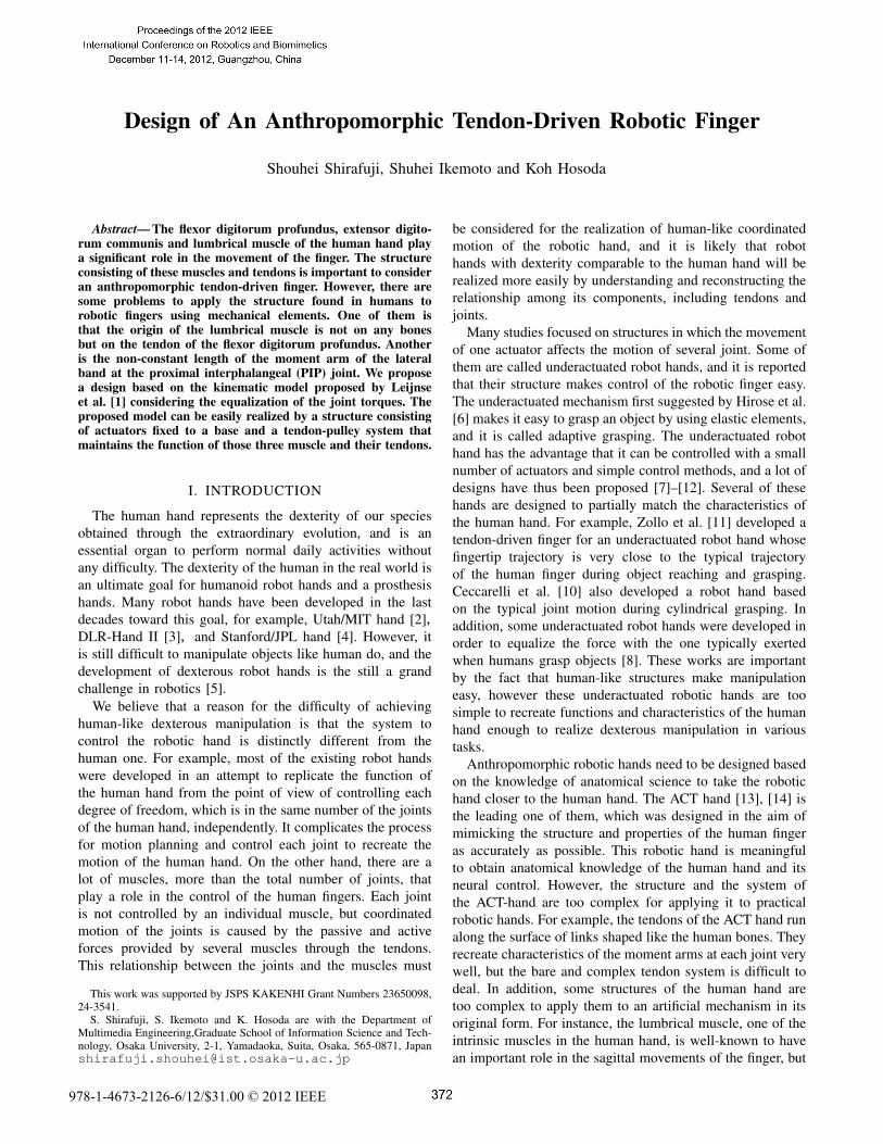
Fig. 1 shows the structure of the human finger. Thereare three joints; the metacarpophalangeal (MP) joint, theproximal interphalangeal (PIP) joint and distal interpha-langeal (DIP) joint, and various activities of five muscles,consisting in the flexor digitorum profundus (FDP), flexordigitorum superficialis (FDS), extensor distrum communis(EC), interosseous (IN) and lumbrical (LU) mainly producemovements of the fingers, with the exception of the thumb.The FDP and FDS muscle provide flexion of the fingers.The EC muscle inserts on the extensor aponeurosis, andallows the extension of the fingers. The lateral band arisesfrom the extensor aponeurosis and attaches to the distalphalanx passing on the PIP joint. The medial band also arisesfrom the extensor aponeurosis and attaches to the proximalphalanx instead. The IN and LU muscles are intrinsic musclewhich insert on the extensor aponeurosis passing the flexorside of the MP joint. The important distinction of the LUmuscle from the IN muscle is that it origins from thetendon of the FDP muscle, while the IN muscle originatesfrom the metacarpal. Electromyographic studies show theLU muscle is selectively activated in some specific motions[15]. Additionally, the LU muscle has high density of musclespindles, which are sensory receptors providing informationabout changes in muscle length. These anatomical knowledgemeans that the activities of LU muscle and the positionalfeedback from the muscle have important role in the controlof the finger.
B. The model of the human finger and problems
Leijnse et al. [1], [16] proposed the kinematic model ofthese muscles and tendons, and analyzed functions of the
DIP joint
PIP jointMP joint
lateral band
medial band
LU muscle and tendonIN muscle and tendon
EC tendon
FDP tendonFDS tendon
Fig. 1. Illustration of muscles and tendons in human index finger.
muscles related to the motion of the human finger consider-ing the slackness or tautness of its non-stretch tendons. Theirmodel is very simple, but properly defined the characteristicsof the human finger system and its motion. We propose thedesign of the anthropomorphic robot finger on the basis oftheir model. Fig. 2 shows their model excluding the FDSand IN muscle. There is some redundancy of the functionbetween the FDP and FDS muscle, and between the LUand IN muscle. In this paper we consider only the threemuscles, the FDP, EC and LU muscle, for simplifying thediscussion of the design of a robotic finger that focuses onthe LU muscle. In addition, these tendons could slack inparticular conditions [1], [16], but we assume that there is noslacks among the tendons of these muscles unless any jointsare constrained by external force or limitations in range ofmotion.
In the model, the tendons of each muscle reach the endpoint through the joints maintaining a certain distance fromthe center of the joint. It can be taken as a structure in whicheach tendon passes through a pulley at each joint twiningaround it. The LU tendon is connected to the FDP tendonin a parallel arrangement, and branches after it passes thepulley on the MP joint. One of the branches is fixed on thepulley at the PIP joint, and another branch is fixed on thepulley at the DIP joint passing another pulley at the PIPjoint. The former branch is the medial band and the latter isthe lateral band. The EC tendon also branches after it passesthe dorsal side of the pulley on the MP joint, and joins thesame root of the LU tendon. The medial and lateral bandare common between the EC and LU tendon. The momentarm length of the pulley of lateral band at PIP joint changesaccording to the angle of the PIP joint in the model to matchthe anatomical knowledge [17].
There are a few problems in applying this model to therobotic finger using machine elements.
• We need to place the actuator on the tendon connectedto the other actuator to mimic the origin of the LUmuscle. It is not easy to realize it using any actuatoravailable today.
• There is a need to realize the root of the tendon whichhas the non-constant moment arm, at PIP joint usingsome machine elements to mimic the characteristics ofthe human joint.
We approach these problems in following sections.
MP joint
DIP joint
EC muscle
LU muscle
FDP muscle
EC tendon
lateral bandmedial band
FDP tendon LU tendons
PIP joint
Fig. 2. Schematic illustration of the model of the human finger based on[1]. But we exclude the FDS and IN muscle here for simplify to discuss.
III. DESIGN OF THE ROBOTIC FINGER
A. Repositioning of the lumbrical muscle
In this section, we consider the equivalent model todisconnect the origin of the LU muscle from the tendon ofthe FDP muscle keeping the joint torques caused by eachmuscle forces. Leijnse et al. [1] uses the equivalent momentarm called systemic moment arm to treat the finger whichhas three joints as biarticular model in order to visualizeits functions. Extending this way of thinking, the equivalentmodel which has the independent LU muscle can be definedfrom the following relation.
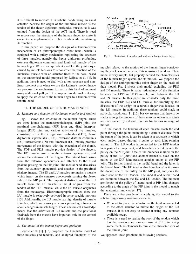
Fig. 3 shows the force applied to the tendons by the actionof each actuator. The variables f∗ means the forces, and fp,fe and fl are the forces exerted by actuators play as the rolesof the FDP, EC and LU muscle. These forces are alwayspositive, and fp is larger than fl under the assumption thatthere are no slacks. The relation of these forces is given by
f∗p = fp − fl (1)
fe = fm + ft (2)fl = flm + flt (3)f∗
t = ft + flt. (4)
The joint torques are determined by the relationship be-tween these forces and the moment arms of each pulley atthe joint. The moment arms are defined by the variable r∗for each pulley (Fig. 4), and the torques are given by
τ1 = rp1f∗p − re1fe + rl1fl (5)
τ2 = rp2f∗p − rm2(fm + flm) − rt2f
∗t (6)
τ3 = rp3f∗p − rt3f
∗t (7)
where τ1, τ2 and τ3 stand for the joint torques at the MP,PIP and DIP joint, and positive torque value indicates a flexorforce. By substituting the equations (1)-(4) into the equations(5)-(7), we obtain the following.
τ1 = rp1fp − re1fe − r∗l1fl (8)τ2 = rp2fp − rm2fm − rt2ft − r∗m2flm − r∗t2flt (9)τ3 = rp3fp − rt3ft − rp3flm − r∗t3flt (10)
where r∗l1, r∗m2, r∗t2 and r∗t3 are newly-defined moment arms
MP joint
PIP joint
DIP jointθ1
θ2
θ3
re1
rp1rl1
rm2
rt2
rt3
rp2
rp3
fe
fp fl
fp*
ft*
fmft
flm
flt
Fig. 3. Forces applied on the tendons by the actuators play roles of themuscles shown in Fig. 2.
re1
rp1
rl1* rm2rt2
rt3
rp2rp3
fe
fp
fl
rt2*
rm2*
rt3*
Fig. 4. Equivalent model of the model described in Fig. 3. The LU muscleis represented as an independent muscle.
given by
r∗l1 = rp1 − rl1 (11)r∗m2 = rp2 + rm2 (12)r∗t2 = rp2 + rt2 (13)r∗t3 = rp3 + rt3. (14)
The equation (8)-(10) can be seen to represent the jointtorques of an equivalent model (Fig. 4). The LU muscleis represented as an independent muscle in this model.The equivalent moment arm of the LU tendon at MP jointexpressed in equation (11) is the same of the one defined in[1] as the systemic moment arm. The length of the momentarms of the LU tendon at PIP and DIP joint become large forextensor side with the length of ones of the FDP tendon. Wenote that the insertion of the lateral band of the LU muscleis changed from the PIP joint to DIP joint in the equivalentmodel.
B. Non-linearly moment arm at DIP joint
In this section we propose a mechanism to change themoment arm according to the angle of the PIP joint. Themoment arm of the lateral band at the PIP joint is changedsignificantly by the movement of the lateral band during theflexing of the PIP joint. This characteristic is important whenconsidering the motion of the finger because it determines
the coupled motion of the interphalangeal joints [16], [18].According to [1], the change of the moment arm satisfies thefollowing the properties
rt2(θ2 = 0) = rm2 (15)
rt2(θ2 =π
2) = 0 (16)
d
dθ2rt2(θ2 =
π
2) = 0. (17)
They used to approximate equation expressed by the second-order polynomial given by
rt2(θ2) = rm2
(1 − 2θ2
π/2+
θ22
(π/2)2
). (18)
This is the most simple expression to meet the condition(15)-(17). However, it is difficult to realize the change of themoment arm fitting the equation (18) in a robotic finger builtby mechanical elements.
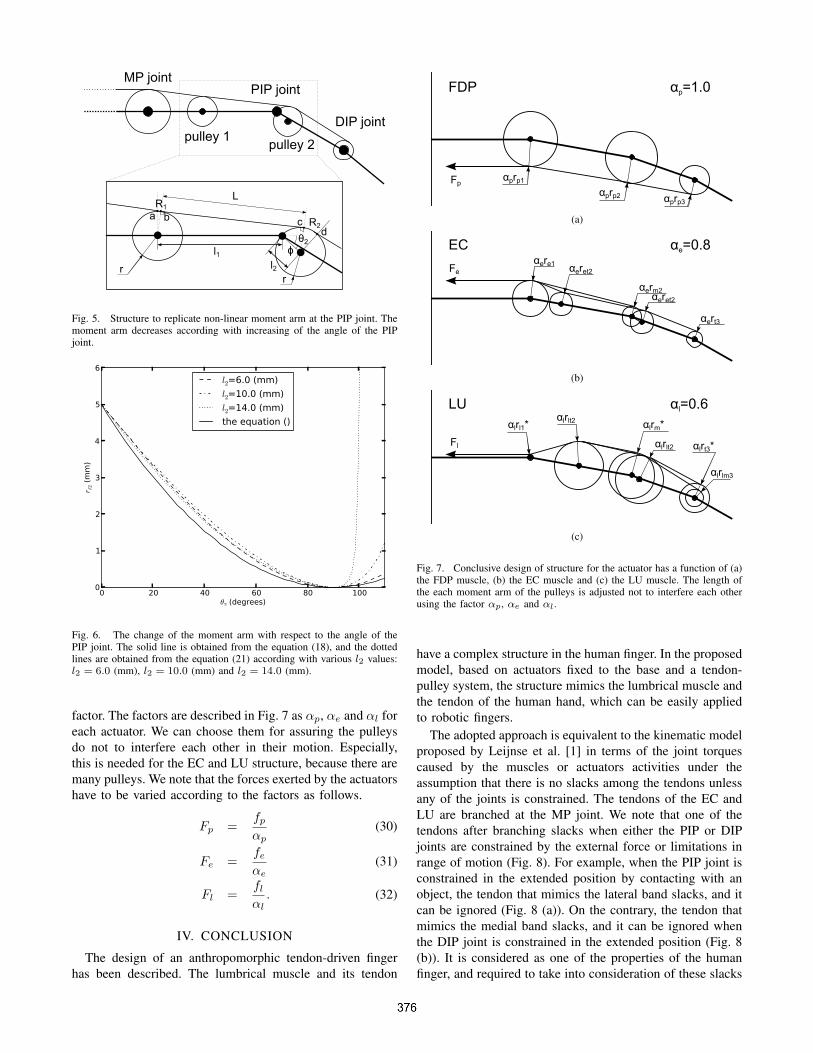
We thus propose a mechanism to change the momentarm according to the range of the PIP joint. Considering todiminish undesirable effects such as friction, it is preferableto use pulleys in the mechanism. Hence we deal here with astructure that has two pulleys, one on each link connected tothe PIP joint (Fig. 5). One of the two pulleys, shown as pulley1 in Fig. 5, is attached to the axis of the link between theMP and PIP joint, and another pulley (pulley 2) is attachedto an axis which is inclined at an angle φ with respect tothe axis of the link between the PIP and DIP joint. φ alsocan be defined as the inclination of the line from the axisof pulley 1 to the PIP joint axis with respect to the axis ofthe link between the MP and PIP joint, or the sum of them.We note that the radii of these pulleys are same, becausethe expressions of the moment arm and the parameters aretoo complex to be defined if these radii are different. Thedistance between the axis of PIP joint and the axis of pulley1 is defined as l1, and l2 is the distance between the PIPjoint and pulley 2. The length of the common tangential lineof pulley 1 and pulley 2 between the contact points b andc is defined as L. R1 is the length of arc (a, b), a is thepoint at the intersection of the circle of pulley 1 with theperpendicular of the line between the axis of pulley 1 andthe PIP joint. R2 is the length of arc (c, d), and d is defined ina similar way. L can be described by the following equationusing the PIP joint angle θ2.
L =√
2l1l2 cos(θ2 + φ) + l21 + l22. (19)
R is the length of the sum of R1 and R2, and also can bedescribed using θ2.
R = R1 + R2 = r(θ2 + φ). (20)
The moment arm of the lateral band at the PIP joint rt2 isrepresented as the change of R and L with respect to thePIP joint angle θ2. Differentiating R and L with respect to
θ2 gives
rt2(θ2) =d
dθ2L +
d
dθ2R
= r − l1l2 sin(θ2 + φ)√2l1l2 cos(θ2 + φ) + l21 + l22
. (21)
Here we have to consider the moment arm defined bythe equation (21) to meet the condition (15)-(17). Firstly,φ is determined from the equation (15) under the conditionl1 ≥ l2.
φ = arccos(− l2l1
) − π
2. (22)
It is found that r has to be equal to l2 from the equation(15).
r = l2. (23)
Finally, l1 is determined from the equation (17).
l1 =l2
√2rm2l∗ − 2l2l∗ − l∗2 + 2l22
l2 − rm2(24)
where l∗ is given by
l∗ =√
2l2rm2 − r2m2. (25)
When l2 is greater than l1, we have to reverse l1 and l2 inthe equations (22)-(25). l2 can be chosen arbitrarily underthe condition given by
2rm2l∗ − 2l2l
∗ − l∗2 + 2l22 ≥ 0. (26)
Fig. 6 shows the change of the moment arm respect withthe angle of the PIP joint. The value of rm2 is used the valuesfrom [19]: rm2 = 5.0 (mm). The solid line is obtained fromthe equation (18) which is used in [1]. Three dotted linesin the figure indicate the change of the moment arm in themechanism we propose. Each line corresponds to variouslength of l2. It can be seen that a sharp rise of the momentarm when l2 is large. We have to choose l2 considering it isnot too large, and the distance between pulley 1 and pulley2 is not too close.
The number of pulleys can be reduced by putting thepulley at MP joint and pulley 1 or the pulley at DIP jointand pulley 2 together, but it is often impossible to meet theconditions described above.
C. Conclusive design
Fig. 7 shows the conclusive design of structure for eachactuator on the basis of the discussion in the previoussections. Some new moment arms are defined as follows.
ret2 = r (27)rlt2 = ret2 + rp2 (28)
rlm3 = rp3 (29)
where r is the radius of the pulley 1 and 2 described inprevious section.
The length of moment arms can be adjusted by multiplyingevery moment arm lengths of the tendon of each actuator by a
MP jointPIP joint
DIP jointpulley 1
pulley 2
l1l2
ϕ
rr
LR1
R2
θ2
a b cd
Fig. 5. Structure to replicate non-linear moment arm at the PIP joint. Themoment arm decreases according with increasing of the angle of the PIPjoint.
Fig. 6. The change of the moment arm with respect to the angle of thePIP joint. The solid line is obtained from the equation (18), and the dottedlines are obtained from the equation (21) according with various l2 values:l2 = 6.0 (mm), l2 = 10.0 (mm) and l2 = 14.0 (mm).
factor. The factors are described in Fig. 7 as αp, αe and αl foreach actuator. We can choose them for assuring the pulleysdo not to interfere each other in their motion. Especially,this is needed for the EC and LU structure, because there aremany pulleys. We note that the forces exerted by the actuatorshave to be varied according to the factors as follows.
Fp =fp
αp(30)
Fe =fe
αe(31)
Fl =fl
αl. (32)
IV. CONCLUSION
The design of an anthropomorphic tendon-driven fingerhas been described. The lumbrical muscle and its tendon
FDP αp=1.0
αprp1
αprp2 αprp3
Fp
(a)
EC αe=0.8
αere1αeret2
αerm2
αert3
αeret2
Fe
(b)
LU αl=0.6
αlrl1* αlrm*αlrlt2
αlrt3*
αlrlm3
Fl αlrlt2
(c)
Fig. 7. Conclusive design of structure for the actuator has a function of (a)the FDP muscle, (b) the EC muscle and (c) the LU muscle. The length ofthe each moment arm of the pulleys is adjusted not to interfere each otherusing the factor αp, αe and αl.
have a complex structure in the human finger. In the proposedmodel, based on actuators fixed to the base and a tendon-pulley system, the structure mimics the lumbrical muscle andthe tendon of the human hand, which can be easily appliedto robotic fingers.
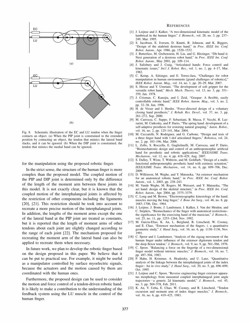
The adopted approach is equivalent to the kinematic modelproposed by Leijnse et al. [1] in terms of the joint torquescaused by the muscles or actuators activities under theassumption that there is no slacks among the tendons unlessany of the joints is constrained. The tendons of the EC andLU are branched at the MP joint. We note that one of thetendons after branching slacks when either the PIP or DIPjoints are constrained by the external force or limitations inrange of motion (Fig. 8). For example, when the PIP joint isconstrained in the extended position by contacting with anobject, the tendon that mimics the lateral band slacks, and itcan be ignored (Fig. 8 (a)). On the contrary, the tendon thatmimics the medial band slacks, and it can be ignored whenthe DIP joint is constrained in the extended position (Fig. 8(b)). It is considered as one of the properties of the humanfinger, and required to take into consideration of these slacks
LU
EC
(a)
EC
LU
(b)
Fig. 8. Schematic illustration of the EC and LU tendon when the fingercontacts an object. (a) When the PIP joint is constrained in the extendedposition by contacting an object, the tendon that mimics the lateral bandslacks, and it can be ignored. (b) When the DIP joint is constrained, thetendon that mimics the medial band can be ignored.
for the manipulation using the proposed robotic finger.In the strict sense, the structure of the human finger is more
complex than the proposed model. The coupled motion ofthe PIP and DIP joint is determined only by the differenceof the length of the moment arm between these joints inthis model. It is not exactly clear, but it is known that thecoupled motion of the interphalangeal joints is affected bythe restriction of other components including the ligaments[20], [21]. This restriction should be took into account torecreate a more precise motion of the interphalangeal joints.In addition, the lengths of the moment arms except the oneof the lateral band at the PIP joint are treated as constants,but it is reported that the length of moment arms of othertendons about each joint are slightly changed according tothe range of each joint [22]. The mechanism proposed forrecreating the moment arm of the lateral band can also beapplied to recreate them when necessary.
In future work, we plan to develop the robotic finger basedon the design proposed in this paper. We believe that itcan be put to practical use. For example, it might be usefulas a manipulator controlled by surface myoelectric signals,because the actuators and the motion caused by them arecoordinated with the human ones.
Furthermore, the proposed design can be used to considerthe motion and force control of a tendon-driven robotic hand.It is likely to make a contribution to the understanding of thefeedback system using the LU muscle in the control of thehuman finger.
REFERENCES
[1] J. Leijnse and J. Kalker, “A two-dimensional kinematic model of thelumbrical in the human finger,” J. Biomech., vol. 28, no. 3, pp. 237–249, Mar. 1995.
[2] S. Jacobsen, E. Iversen, D. Knutti, R. Johnson, and K. Biggers,“Design of the utah/mit dextrous hand,” in Proc. IEEE Int. Conf.Robot. Autom., Apr. 1986, pp. 1520–1532.
[3] J. Butterfass, M. Grebenstein, H. Liu, and G. Hirzinger, “Dlr-hand ii:Next generation of a dextrous robot hand,” in Proc. IEEE Int. Conf.Robot. Autom., May 2001, pp. 109–114.
[4] J. Salisbury and J. Craig, “Articulated hands: Force control andkinematic issues,” Int.l J. Robot. Res., vol. 1, no. 1, pp. 4–17, Mar.1982.
[5] C. Kemp, A. Edsinger, and E. Torres-Jara, “Challenges for robotmanipulation in human environments [grand challenges of robotics],”IEEE Robot. Autom. Mag., vol. 14, no. 1, pp. 20–29, Mar. 2007.
[6] S. Hirose and Y. Umetani, “The development of soft gripper for theversatile robot hand,” Mech. Mach. Theory, vol. 13, no. 3, pp. 351–359, Jan. 1978.
[7] J. Crisman, C. Kanojia, and I. Zeid, “Graspar: A flexible, easilycontrollable robotic hand,” IEEE Robot. Autom. Mag., vol. 3, no. 2,pp. 32–38, Jun. 1996.
[8] H. de Visser and J. Herder, “Force-directed design of a voluntaryclosing hand prosthesis,” J. Rehab. Res. Devel., vol. 37, no. 3, pp.261–272, Sep. 2000.
[9] M. Carrozza, C. Suppo, F. Sebastiani, B. Massa, F. Vecchi, R. Laz-zarini, M. Cutkosky, and P. Dario, “The spring hand: development of aself-adaptive prosthesis for restoring natural grasping,” Auton. Robot.,vol. 16, no. 2, pp. 125–141, Mar. 2004.
[10] M. Ceccarelli, N. Rodriguez, and G. Carbone, “Design and tests ofa three finger hand with 1-dof articulated fingers,” Robotica, vol. 24,no. 2, pp. 183–196, Mar. 2006.
[11] L. Zollo, S. Roccella, E. Guglielmelli, M. Carrozza, and P. Dario,“Biomechatronic design and control of an anthropomorphic artificialhand for prosthetic and robotic applications,” IEEE/ASME Trans.Mechatron., vol. 12, no. 4, pp. 418–429, Aug. 2007.
[12] S. Dalley, T. Wiste, T. Withrow, and M. Goldfarb, “Design of a multi-functional anthropomorphic prosthetic hand with extrinsic actuation,”IEEE/ASME Trans. Mechatron., vol. 14, no. 6, pp. 699–706, Dec.2009.
[13] D. Wilkinson, M. Weghe, and Y. Matsuoka, “An extensor mechanismfor an anatomical robotic hand,” in Proc. IEEE Int. Conf. Robot.Autom., vol. 1, 2003, pp. 238–243.
[14] M. Vande Weghe, M. Rogers, M. Weissert, and Y. Matsuoka, “Theact hand: design of the skeletal structure,” in Proc. IEEE Int. Conf.Robot. Autom., Apr. 2004, pp. 3375–3379.
[15] C. Long and M. Brown, “Electromyographic kinesiology of the hand:muscles moving the long finger,” J. Bone Jnt Surg., vol. 46, no. 8, pp.1683–1706, Dec. 1964.
[16] J. Leijnse, J. Bonte, J. Landsmeer, J. Kalker, J. Van der Meulen, andC. Snijders, “Biomechanics of the finger with anatomical restrictions–the significance for the exercising hand of the musician,” J. Biomech.,vol. 25, no. 11, pp. 1253–1264, Nov. 1992.
[17] M. Garcia-Elias, K. An, L. Berglund, R. Linscheid, W. Cooney,and E. Chao, “Extensor mechanism of the fingers. i. a quantitativegeometric study,” J. Hand Surg., vol. 16, no. 6, pp. 1130–1136, Nov.1991.
[18] C. Spoor and J. Landsmeer, “Analysis of the zigzag movement of thehuman finger under influence of the extensor digitorum tendon andthe deep flexor tendon,” J. Biomech., vol. 9, no. 9, pp. 561–566, 1976.
[19] C. Spoor, “Balancing a force on the fingertip of a two-dimensionalfinger model without intrinsic muscles,” J. Biomech., vol. 16, no. 7,pp. 497–504, 1983.
[20] P. Hahn, H. Krimmer, A. Hradetzky, and U. Lanz, “Quantitativeanalysis of the linkage between the interphalangeal joints of the indexfinger:: An in vivo study,” J. Hand Surg., vol. 20, no. 5, pp. 696–699,Oct. 1995.
[21] J. Leijnse and C. Spoor, “Reverse engineering finger extensor appara-tus morphology from measured coupled interphalangeal joint angletrajectories―a generic 2d kinematic model,” J. Biomech., vol. 45,no. 3, pp. 569–578, Feb. 2011.
[22] K. An, Y. Ueba, E. Chao, W. Cooney, and R. Linscheid, “Tendonexcursion and moment arm of index finger muscles,” J. Biomech.,vol. 16, no. 6, pp. 419–425, 1983.