Embed Size (px)
Citation preview
1American Institute of Aeronautics and Astronautics
Design, Commissioning and Control System of a Hybrid Rocket Test Cell
Ray Wilkinson1, Ken Hart2, and Rodney Day3 University of Hertfordshire, Hatfield, AL10 9AB, UK
andIan Coxhill4
AMPAC-ISP (UK) Limited, Aylesbury, HP18 0NZ, UK
A rocket-motor test cell, capable of carrying out instrumented firings of hybrid and composite motors of up to 5kN (1100lb) thrust and up to 8 feet in length, has been installed at the University of Hertfordshire, UK. The key features and requirements of the design are described, especially with regard to the hazards considered. Details of the control system design are also discussed. The paper details the safety features, interlocks and operational safety considerations incorporated, then concludes with a discussion of the operational experience gained over more than sixty firings of all types, a review of the modifications made and how the design and implementation might have been improved in light of this experience.
I. Introduction
To further the research and teaching capability at the University of Hertfordshire for both undergraduate and post-graduate work, a new rocket test cell was procured. This was principally aimed at test firings of hybrid rocket
motors up to 1100lb thrust (½ tonne or 5kN) and 20,000Ns total impulse, although it is also capable of firing composite (solid) motors of similar size. Due to the location of the test cell, which was in an aerodynamics laboratory and close to a service road, there were a number of key safety points to be addressed, including noise control and the risk of explosion. The control system installed, which was custom-built, enables the firing of solid and hybrid motors in a number of configurations, and features interlocks to provide the necessary safety, as well as minimising wasted propellants.
II. Test Cell DesignAside from the performance requirements, the key features of the design of the cell itself were the space available,
the discharge of combustion products and exhaust efflux, noise control and safe operation. Although Hertfordshire is a multi-campus university, with around 12,000 students on this site and some 25,000 overall, there is limited space on the site. The optimum location for the test cell was found to be in an aerodynamics laboratory adjacent to a supersonic wind tunnel. This was suitable for several reasons:
1) It would fit into an unused space, as the supersonic tunnel has an L-shaped planform, which inherently limits access.
2) The supersonic tunnel exhausts through the wall into a brick-built duct, directing the noise and air upwards. The exhaust duct for the rocket cell could be located alongside this duct.
3) There is a warning system, intended to stop vehicle and foot traffic when a firing is imminent, and the test cell could make use of this system if required.
4) The remaining space in this lab was already dedicated to rocketry activities.Since the test cell was inside an existing building, the requirements were somewhat simplified, as there were no
weather considerations to take into account. The construction of the test cell was a choice of a brick- or block-built cell with a concrete or multi-layer roof, or an acoustic enclosure built by a commercial specialist. It was decided that the
1) Principal Lecturer, School of Engineering and Technology, Member AIAA.2) Principal Lecturer, School of Engineering and Technology.3) Principal Lecturer, School of Engineering and Technology.4) Chief Engineer, Member AIAA.
46th AIAA/ASME/SAE/ASEE Joint Propulsion Conference & Exhibit25 - 28 July 2010, Nashville, TN
AIAA 2010-6934
Copyright © 2010 by University of Hertfordshire. Published by the American Institute of Aeronautics and Astronautics, Inc., with permission.
2American Institute of Aeronautics and Astronautics
fabrication would be contracted to a specialist company. Although more expensive, this gave a number of advantages – the noise-reduction capabilities would be accurately predicted, and the modular nature of the design offered would be capable of relocation, as a new building for the School is planned in the future.
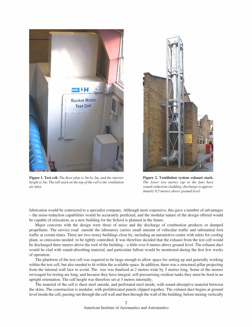
Major concerns with the design were those of noise and the discharge of combustion products or dumped propellants. The service road outside the laboratory carries small amount of vehicular traffic and substantial foot traffic at certain times. There are two-storey buildings close by, including an automotive centre with inlets for cooling plant, so emissions needed to be tightly controlled. It was therefore decided that the exhaust from the test cell would be discharged three metres above the roof of the building – a little over 8 metres above ground level. The exhaust duct would be clad with sound-absorbing material, and particulate fallout would be monitored during the first few weeks of operation.
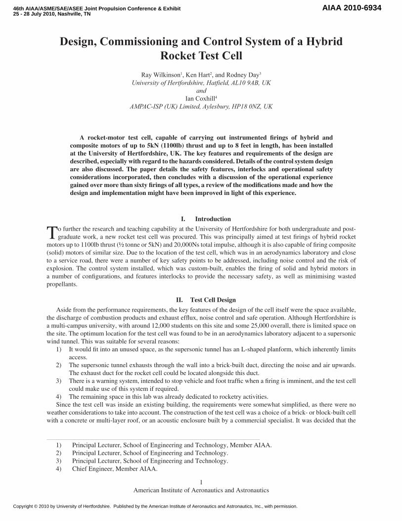
The planform of the test cell was required to be large enough to allow space for setting up and generally working within the test cell, but also needed to fit within the available space. In addition, there was a structural pillar projecting from the internal wall face to avoid. The size was finalised at 2 metres wide by 3 metres long. Some of the motors envisaged for testing are long, and because they have integral, self-pressurising oxidiser tanks they must be fired in an upright orientation. The cell height was therefore set at 3 metres internally.
The material of the cell is sheet steel outside, and perforated steel inside, with sound-absorptive material between the skins. The construction is modular, with prefabricated panels clipped together. The exhaust duct begins at ground level inside the cell, passing out through the cell wall and then through the wall of the building, before turning vertically
Figure 1. Test cell. The floor plan is 3m by 2m, and the interior height is 3m. The tall stack on the top of the cell is the ventilation air inlet.
Figure 2. Ventilation system exhaust stack. The lower two metres (up to the fan) have sound-reduction cladding; discharge is approx-imately 8.5 metres above ground level.
3American Institute of Aeronautics and Astronautics
and being attached to the building’s outer wall. The lower section is of 400mm diameter steel of 10mm (3/8-inch) wall thickness. The upper section is also 400mm diameter, but of thin-wall stainless steel, lagged with acoustic material for the first two metres. Above this lagging is a fan, capable of moving 1.5 m3/sec at its rated pressure head. The motors that may be fired may exceed this flow rate – possibly up to 4m3/second – but the motor exhaust will normally be directed at the duct entrance so will assist the fan. The flow rate of the fan means the air within the test cell will be changed approximately every 10 seconds, so any remaining combustion gases will be quickly expelled.
Due to the small but finite risk of explosion, it was decided that the cell would not contain windows, and all activities related to firings would be carried out remotely, monitored using a pair of High-Definition video cameras and large-screen monitor. This makes the test cell well suited to teaching and demonstration firings with small groups. It is important that the door, which opens outwards for space reasons, is securely latched, especially since the layout dictates that the motor, door and users are in line – this is discussed further in the section on safety. The likely effects of motor casing failures and similar incidents also had a bearing on the cell design.
Since the monitoring was to be carried out through video feeds, it was considered that the brightness of the exhaust plume would cause the cameras irises to stop down, limiting the view to the plume only. To reduce this, lighting levels within the test cell are high, with three twin-tube fluorescent lights inside. The lights are individually switched to allow lower levels when setting up.
III. Control SystemThe control system for the test cell was required to fulfil a number of requirements. In addition to the basic operations
to fire solid motors, it must be able to operate hybrid motors of two variants – hybrids using self-pressurising, integral oxidiser tanks, of the type used by amateur rocketeers, and motors using a separate tank. In the latter case, an oxidiser a feed is provided directly from a 55-litre or 20-litre cylinder. Control of oxidiser flow is achieved using solenoid valves, and the location of these valves in relation to the feed/fill pipes is different for the two cases described. The additional function of firing composite motors is straightforward.
In addition, the control system required a number of interlocks to disable the control system unless the cell door is closed and the ventilation system is running. The door interlock is a simple micro-switch, connected to the main firing panel. It was agreed with the contractor that switching of the ventilation system would be triggered using a 12V feed from the control system, removing the need for a separate ventilation switch and switch-plate, and simplifying operation. The ventilation was initially inhibited until the door is closed, to prevent slamming and possible injury given the high flow rates achievable. Following installation this was found not to be a problem, and the setup has since been modified to allow the ventilation to run with the door open. Another feature of the control system is a master keyswitch to disable all panel functions; the keyswitch can only be removed in the Off position, and the operating procedure dictates that the key be removed and taken into the cell when setting up. Only one key is in use, and it is fitted with a paddle some 6 inches in diameter, in the manner of old-style hotel keys, to help prevent users taking it away accidentally.
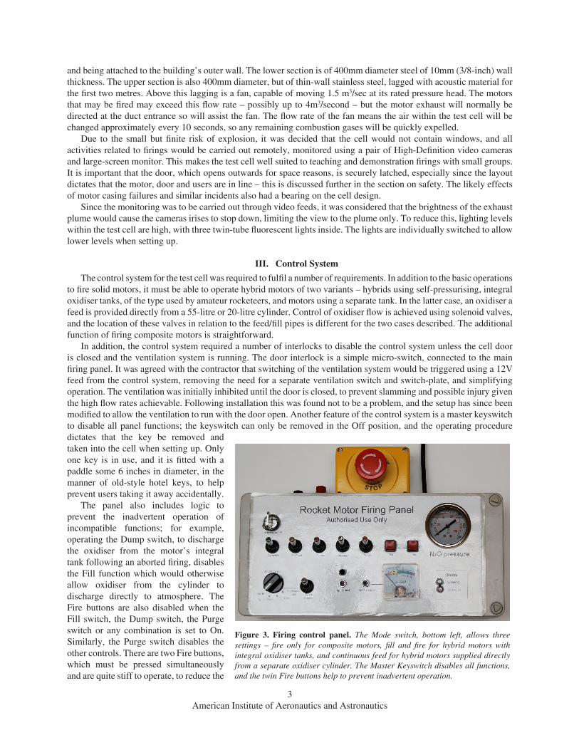
The panel also includes logic to prevent the inadvertent operation of incompatible functions; for example, operating the Dump switch, to discharge the oxidiser from the motor’s integral tank following an aborted firing, disables the Fill function which would otherwise allow oxidiser from the cylinder to discharge directly to atmosphere. The Fire buttons are also disabled when the Fill switch, the Dump switch, the Purge switch or any combination is set to On. Similarly, the Purge switch disables the other controls. There are two Fire buttons, which must be pressed simultaneously and are quite stiff to operate, to reduce the
Figure 3. Firing control panel. The Mode switch, bottom left, allows three settings – fire only for composite motors, fill and fire for hybrid motors with integral oxidiser tanks, and continuous feed for hybrid motors supplied directly from a separate oxidiser cylinder. The Master Keyswitch disables all functions, and the twin Fire buttons help to prevent inadvertent operation.
4American Institute of Aeronautics and Astronautics
possibility of inadvertent firing. A low-current circuit is connected to the igniter leads, bypassing the relay, giving an audible signal to show igniter continuity. The current drawn is a few milliamps, less than that required to fire a typical pyrotechnic igniter.
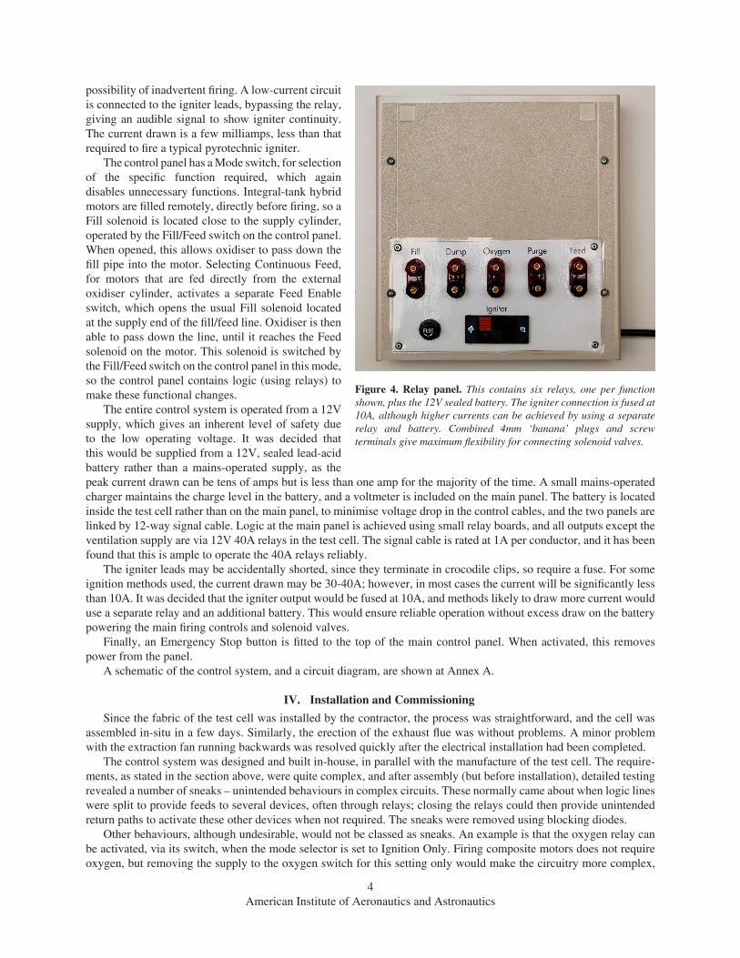
The control panel has a Mode switch, for selection of the specific function required, which again disables unnecessary functions. Integral-tank hybrid motors are filled remotely, directly before firing, so a Fill solenoid is located close to the supply cylinder, operated by the Fill/Feed switch on the control panel. When opened, this allows oxidiser to pass down the fill pipe into the motor. Selecting Continuous Feed, for motors that are fed directly from the external oxidiser cylinder, activates a separate Feed Enable switch, which opens the usual Fill solenoid located at the supply end of the fill/feed line. Oxidiser is then able to pass down the line, until it reaches the Feed solenoid on the motor. This solenoid is switched by the Fill/Feed switch on the control panel in this mode, so the control panel contains logic (using relays) to make these functional changes.
The entire control system is operated from a 12V supply, which gives an inherent level of safety due to the low operating voltage. It was decided that this would be supplied from a 12V, sealed lead-acid battery rather than a mains-operated supply, as the peak current drawn can be tens of amps but is less than one amp for the majority of the time. A small mains-operated charger maintains the charge level in the battery, and a voltmeter is included on the main panel. The battery is located inside the test cell rather than on the main panel, to minimise voltage drop in the control cables, and the two panels are linked by 12-way signal cable. Logic at the main panel is achieved using small relay boards, and all outputs except the ventilation supply are via 12V 40A relays in the test cell. The signal cable is rated at 1A per conductor, and it has been found that this is ample to operate the 40A relays reliably.
The igniter leads may be accidentally shorted, since they terminate in crocodile clips, so require a fuse. For some ignition methods used, the current drawn may be 30-40A; however, in most cases the current will be significantly less than 10A. It was decided that the igniter output would be fused at 10A, and methods likely to draw more current would use a separate relay and an additional battery. This would ensure reliable operation without excess draw on the battery powering the main firing controls and solenoid valves.
Finally, an Emergency Stop button is fitted to the top of the main control panel. When activated, this removes power from the panel.
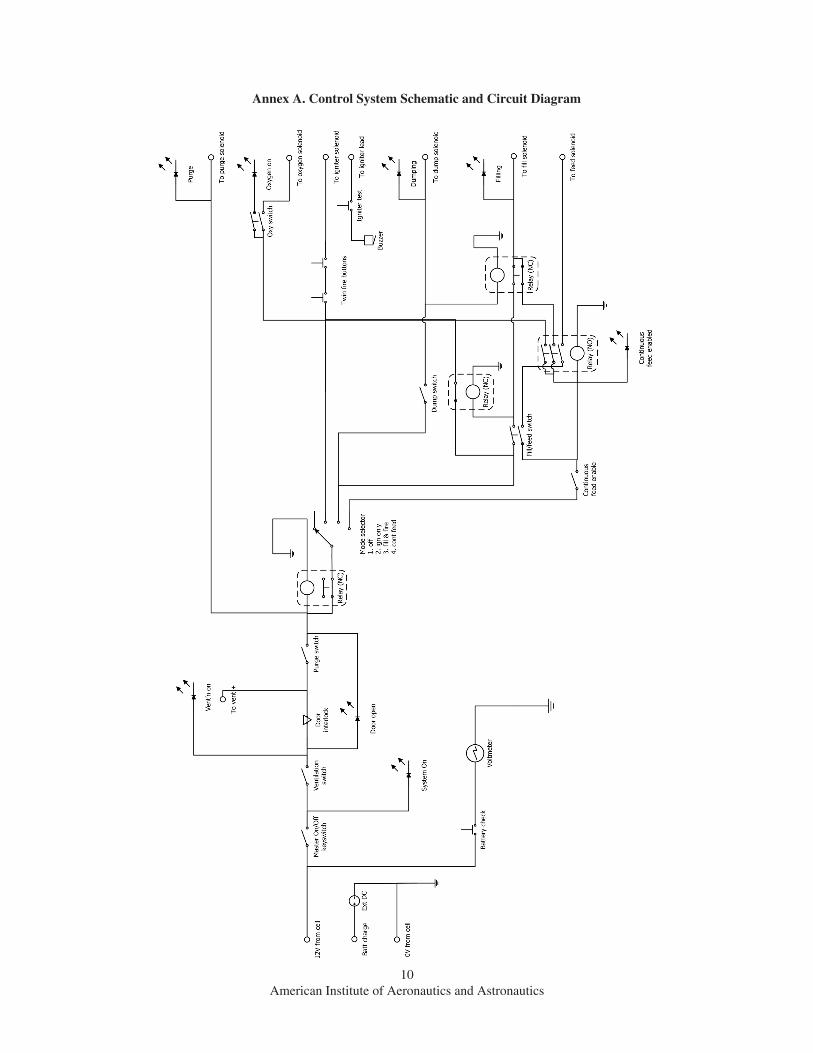
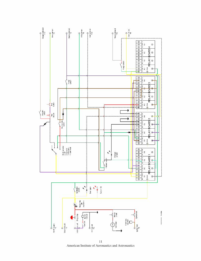
A schematic of the control system, and a circuit diagram, are shown at Annex A.
IV. Installation and CommissioningSince the fabric of the test cell was installed by the contractor, the process was straightforward, and the cell was
assembled in-situ in a few days. Similarly, the erection of the exhaust flue was without problems. A minor problem with the extraction fan running backwards was resolved quickly after the electrical installation had been completed.
The control system was designed and built in-house, in parallel with the manufacture of the test cell. The require-ments, as stated in the section above, were quite complex, and after assembly (but before installation), detailed testing revealed a number of sneaks – unintended behaviours in complex circuits. These normally came about when logic lines were split to provide feeds to several devices, often through relays; closing the relays could then provide unintended return paths to activate these other devices when not required. The sneaks were removed using blocking diodes.
Other behaviours, although undesirable, would not be classed as sneaks. An example is that the oxygen relay can be activated, via its switch, when the mode selector is set to Ignition Only. Firing composite motors does not require oxygen, but removing the supply to the oxygen switch for this setting only would make the circuitry more complex,
Figure 4. Relay panel. This contains six relays, one per function shown, plus the 12V sealed battery. The igniter connection is fused at 10A, although higher currents can be achieved by using a separate relay and battery. Combined 4mm ‘banana’ plugs and screw terminals give maximum flexibility for connecting solenoid valves.
5American Institute of Aeronautics and Astronautics
potentially affecting reliability.Installation of the control panel and relay panel was straightforward, and the interface to the ventilation system was
simply a case of connecting two wires to the 12V contactor provided by the manufacturer. Initially it was found that the ventilation fan ran in reverse, and this was traced to incorrect wiring of the three-phase connections during instal-lation. An isolator switch was fitted outside the building to permit easy maintenance of the fan motor, and this was fitted with a padlock to prevent unauthorised operation – this was a safety matter since the indicators and interlocks in the control system show only that power is supplied to the ventilation, not that the ventilation fan is actually running. However, the ventilation is audible (although barely so) when running, and is noticeable especially through the audio feed from the cameras.
There were no other problems during commissioning, and the first firing in the test cell, of a small composite motor, was carried out in early March, 2009.
V. SafetyEvidently with facilities of this nature, safety is a key concern. One of the processes that was undertaken as part
of the design process was a full risk assessment, identifying all known hazards and how they are addressed. This comprehensive document produced a number of minor surprises, and this process was an essential part of the process of specifying the test cell and defining its operational procedures.
The interlocks already described provide a high degree of safety in the operation of the facility:1) A keyswitch, with the key removable only in the Off position, disables the panel completely, and the procedures
require the key to be removed and taken into the cell during setting up.2) The test cell controls for all functions are disabled until the door interlock indicates the door is closed and the
ventilation system is powered up.3) The Fire functions are disabled whilst filling or dumping from the tank in an integral tank hybrid motor.4) An emergency stop switch removes all power from the panel, disabling all functions.Other considerations can be broadly divided into a number of key areas:
A. NoiseThe noise levels from firing rocket motors, even small ones, can be in excess of 120dBA close up, and are dependent
on surrounding buildings (when fired outdoors), adjacent structure (indoors) and the orientation of both the motor and the observer in relation to them. Clearly, there is a need to control this to ensure safety to both the personnel involved and other people in the vicinity. One of the justifications for procuring this test cell, in the prevailing difficult economic environment, was the need to ensure the noise hazard is controlled – previous testing took place outdoors but was found to be unsatisfactory due to noise concerns.
The test cell has a known acoustic performance, and the contractor provided a statement on noise abatement across the frequency spectrum. In use, noise levels adjacent to the test cell have been observed to be very low, and the principal source of the noise from any firing is from the TV speakers, via the microphone on the cameras within the test cell. This of course can be adjusted to a suitable volume.
Outside the building, adjacent to the exhaust stack, noise levels are again strongly muted, and most passers by are completely unaware of the firing. The acoustic treatment to the lower section of the duct, plus the elevated position of the discharge point, reduce the sound levels to a point where no warning system or access control are required in the vicinity. This situation is not expected to change with even the largest motors, but will be monitored as use of the test cell continues.
B. Asphyxiation and toxicityThere are two principal problems to consider in this respect – the removal or displacement of oxygen as a result of
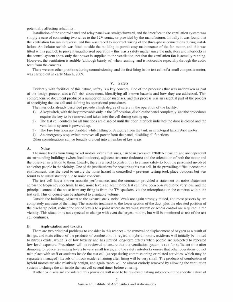
firings, and toxic effects of the products of combustion. In regard to hybrid motors, oxidisers will initially be limited to nitrous oxide, which is of low toxicity and has limited long-term effects when people are subjected to repeated low-level exposure. Procedures will be reviewed to ensure that the ventilation system is run for sufficient time after dumping to reduce remaining levels to very small traces, and the safety interlocks ensure that other operations do not take place with staff or students inside the test cell (except during commissioning or related activities, which may be separately managed). Levels of nitrous oxide remaining after firing will be very small. The products of combustion of hybrid motors are also relatively benign, and again traces will be almost entirely removed by allowing the ventilation system to change the air inside the test cell several times before entering.
If other oxidisers are considered, this provision will need to be reviewed, taking into account the specific nature of

6American Institute of Aeronautics and Astronautics
the oxidisers concerned. It is anticipated this would be limited to hydrogen peroxide and carbon dioxide.For composite (AP-based) motors, the combustion products are rather more unpleasant, containing carbon monoxide,
hydrogen chloride, ammonia and alumunium oxide (as particulates of varying sizes). However, the effects are consid-erably more irritating than hazardous, and again the ventilation system will remove almost all of the compounds before entry to the test cell. In the event significant amounts of residue gases remain (for example after firing a large motor), then the air inside the test cell will discourage entry until levels fall. The delay before entry is set longer for larger motors (above 2500Ns impulse) to give more time for the gases to be expelled.
The discharge point is over eight metres above ground level, minimising the concentrations of combustion products in the air at ground level. The length of the vertical section of the vent stack, combined with the flow rate, is likely to cause larger particles to fall back within the stack rather than be ejected. These particles will collect at the bottom of the stack where they will mix with rainwater and be flushed as the rainwater drains.
C. Heat and burnsThe temperatures involved with the firing of both hybrid and solid motors are high – combustion flame tempera-
tures can exceed 3500K within the combustion chamber, and exhaust plume temperatures may exceed 2200K [1]. Materials used inside the test cell are selected with this in mind, and procedures have been written to encompass this. The vent is made of 10mm thick steel, and the test stands are configured so that the exhaust plume will not come into contact with the vent pipe until some distance from the nozzle. For motors fired vertically, the plume will be directed onto a ceramic tile, then deflected at right angles into the vent, at a reasonable distance. Horizontally fired motors will be set at a distance from the vent pipe to protect it from heat damage.
The operating procedures contain warnings about the risk of burns after firing, and indicate the parts that are likely to become hot.
One other related hazard is connected with the use of nitrous oxide, which is cryogenic. Thus, if nitrous oxide is sprayed from a pipe or motor onto the skin or eyes, it may cause damage normally referred to as ‘freezer burns’. The procedures require that, in all operations where there is a risk of this, those involved wear suitable PPE, including gloves and safety glasses.
In the event of a catastrophic motor failure, primarily in respect of solid motors, burning propellant may be ejected into the test cell. The construction of the test cell is such that this will not cause any direct damage to the cell, nor will it support combustion once the burning propellant has extinguished. The failure is likely to be associated with a sudden drop in pressure, which normally extinguishes composite propellant immediately. Since the propellant contains its own oxygen and may release considerable energy, the use of a fire extinguisher at this point is likely to be superfluous. However, it will be necessary to extinguish any remaining burning and an extinguisher is located immediately outside the test cell for this purpose. Similarly, any fire caused inside the test cell by other means may create a hazard if composite propellant is in the vicinity. The operating procedures contain information about the storage and handling of composite propellants, and the extinguisher may be used to contain any fire quickly.
Experience with flying amateur rockets has shown that in rare cases premature operation of igniters is possible. The causes vary, and are often impossible to determine after such an event, but may include faults in firing circuits, static electricity, incorrect procedures and electromagnetic interference from sources such as mobile phones. When this occurs with an igniter installed, or in the process of installation, in a composite motor, the motor will normally fire without warning. If such an event occurs with a hybrid motor, it is normally less hazardous since the motor will not fire. The procedure that has been developed is therefore to assume that connecting the igniter WILL result in its initiation, and therefore must be carried out at arm’s length and with head and eyes averted. Operators are required to ensure they are not in the path of the exhaust plume. Briefly touching the terminals of the igniter lead together before connection will generate a spark if power is already applied, and dissipates static electricity. Since this procedure has been adopted (on the launch range as well as in the test cell), there have been no incidents of this type.
Finally, composite propellants, igniters and other combustibles are stored in a secure area remote from the test cell, and the operating procedures require that all such materials not required for the test in progress are kept in this secure area until required.
D. Explosions and flying debrisDue to the energy involved in many of the motors to be fired, the risk of explosion, although small, carries serious
consequences. Severe damage may be caused to the test cell, but in the event that debris is projected out of the cell, injuries to people may result. Clearly, this is quite evident at an early stage, but the risk assessment exercise referred to earlier led to a detailed reconsideration of all the risks involved.

7American Institute of Aeronautics and Astronautics
For small motors, the energy release will be small, and it is reasonable to expect that any fragments will be contained by the test cell walls. The overpressure from a catastrophic failure will again be contained by the structure of the cell, assisted by the flow rate of the extraction system. It is possible the there may be some flow through the inlet duct on top of the cell, but the volume of the laboratory in which the test cell is housed is large, and no adverse effects are expected. At worst, the ability of the door latch to hold the door closed against the overpressure may be exceeded. In this case, the effect of the door in providing a barrier to protect the users and observers of the test cell is removed. This is a particular difficulty since, as already stated, the control panel and observation point is in line with the door due to constraints on the location.
However, many motors will be fired in a vertical position, and the location of the exhaust duct allows for a protective plate to be fitted to test stands. After reviewing this particular hazard, it was decided to require a thick plate to be fitted to all test stands as a blast shield, possibly reinforced with Kevlar to provide extra resistance to fragment penetration. All test stands are bolted to the floor, and with large motors it may be necessary to consider carefully the bolting arrangement to ensure the stand will not be toppled if a casing fails catastrophically.
With hybrid motors, the probability of a chemical explosion is very small, although such occurrences are not unknown. There remains, however, the possibility of a case rupture due to combustion chamber overpressure or, less likely, oxidiser tank overpressure. The primary design failure mode of integral-tank hybrid motors is to eject the fore and aft closures. In this case, the aft closure will be ejected onto the blast shield, and from there into the exhaust duct. This is not expected to create a hazard to people in the vicinity. The forward closure will travel upwards, striking the ceiling of the test cell. A plate has been specified as part of the cell, located directly over the motor position, and this plate is of a top-hat design, with a space between the plate and the ceiling, giving room for deformation, and is replaceable. It cannot be assumed that motors can only fail in their design mode, so allowance must be made for the possibility that the case itself (including the tank) may rupture. In this case, fragments may be ejected laterally. Protection is provided in the same way as for solid motors, by the test cell structure, enhanced by the blast shields on the test stands.
In the event that larger motors fail, it is possible that the test cell walls may not contain the fragments. The operating procedures therefore specify that for all firings of motors in excess of 2500Ns total impulse, the laboratory is to be cleared of personnel not involved in the test, and that all those involved with the test, including observers, are located at the observation point, where protection is offered by the plates fitted to the test stands. Although total impulse is not an exact measure of the severity of any unforeseen failure, it gives an indication of stored energy. A more-sophisticated set of criteria, perhaps referring to thrust, motor type and total impulse, would be difficult to establish and administer, and is somewhat arbitrary in any case since the correlation between these parameters and the risk of, and damage caused by, an explosion are unknown.
To protect users of the test cell, it was decided that it would be standard practice to place a blast shield between the motor and the door. This blast shield, which can normally be incorporated into the test stand, must be strong enough to absorb a reasonable amount of ejected debris, and also securely attached to the floor to resist rolling over when subjected to the pressure field. When it is built as part of the stand, the latter requirement is automatically met to a large degree. In practice, a shield is not strictly necessary for all firings, particularly horizontally mounted motors, since the load cell and its support structure may provide adequate protection against ejected debris for motors of modest impulse.
Although it is clearly preferable not to place nitrous oxide cylinders within the test cell, and to supply all hybrid motors from outside, the option to permit cylinders to be used inside the cell was carefully considered. There are two primary risks associated with this – that the heat generated in the cell will raise the nitrous oxide in the cylinder above its critical point at around 37°C, and the large pressure rise as the liquid becomes gas will rupture the cylinder; and that an explosion within the test cell will cause the cylinder to rupture through fragments penetration. The former case is almost impossible, since the heat capacity of the cylinder and its contents, even when almost empty, would require extremely high temperatures sustained for long periods before significant pressure rises could occur. The latter case is of more concern, but the cylinder has a large factor of safety, and is made from ductile steel. Fragments of sufficient energy to penetrate the cylinder would only be generated by a failure that in itself would be catastrophic to the test cell and surroundings. Whilst the additional energy donated by an exploding cylinder of nitrous oxide would exacerbate the severity, a firing of sufficient magnitude to create this fragment energy would already have required a separate risk assessment, and the potential presence of the cylinder would be taken into account, and disallowed.
VI. CostThe total cost of installing the test cell, including the contracted manufacture and installation of the cell itself,
with the extraction system, separate contractors for the installation of the power supplies, and the cost of all hardware
8American Institute of Aeronautics and Astronautics
sourced separately, was about £50,000 (US$78,000). Not included is the labour of university personnel to design and build the control system and also agreeing and specifying the requirements. With the exception of propellants and the minor upgrades detailed in the next section, no repairs or running costs beyond electricity have been incurred to date. Periodic cleaning of the test cell, especially the lighting, has been identified as a necessity.
VII. Operational ExperienceAt the time of writing, over 60 firings have been carried out in the test cell, operating the system in all three
functional modes. This includes a series of 34 firings of composite motors, of various sizes, in a single day. Each of these firings included producing a thrust curve and a video recording of the firing. Firings of integral-tank hybrid motors up to a nominal 1500Ns of total impulse have been carried out, and also of hybrid motors without an integral tank, of up to 300N thrust. The largest impulse firing to date was over 4000Ns, comprising a hybrid motor of 200N thrust and a burn duration of 23 seconds. This motor was supplied with oxidiser from a cylinder located within the test cell.
With such experience now accumulated, some reflection on the design of the test cell is possible. It has been observed that installing motors vertically tends to discharge large amounts of smoke into the cell, which then takes some time to be extracted by the ventilation system. A composite motor even of very small impulse, say 50Ns, creates sufficient smoke within the test cell to obscure the camera’s view within a fraction of a second, and this takes several minutes to clear. Conversely, a composite motor of around 2500Ns impulse fired horizontally, so that the exhaust plume is directed at the extraction flue, discharges almost no smoke into the test cell itself, and the view by the camera is completely unobstructed. However, given the incremental cost involved, a larger-capacity extraction system would have been specified had this experience been available at the time the test cell was ordered. In addition, all motors are now fired in a horizontal attitude wherever possible.
The original assumptions about the procedure immediately after a firing have been shown to be slightly incorrect. It was assumed that the smoke would always clear quickly, and that entry to the test cell would not take place until it was completely clear. However, it would be convenient to enter the test cell more quickly, and then to leave the door open to allow fresh air to enter the test cell. With the original setup, the ventilation was inhibited when the door is open. This has now been reconfigured so that the fan will continue when the door is opened, allowing earlier entry without hazard to the operators. Provided the smoke has mostly cleared, there is no release of combustion gases into the main laboratory area due to the high extraction rate.
The location of the mouth of the extractor flue projects about 200mm (8 inches) into the test cell, close to ground level. When a hybrid motor is installed in a vertical attitude, it is desirable to place the nozzle close enough to the flue to limit smoke discharge into the cell itself, but far enough away to avoid the possibility of damage to the flue. However, this places the motor close to the test cell wall, and the view from the cameras is limited. Since it is not possible to fit wide-angle adaptors to these particular cameras, this places a limitation on what can be observed. Having two cameras alleviates this problem to some extent, as would extending the vent further into the cell and relocating the motor test fixture, but this is a factor that had not been considered when specifying the test cell. Installing motors horizontally, when possible, largely overcomes this problem as it is possible to raise the camera positions, taking them further from the motor.
It has been found that all firings, whether they discharge visible smoke into the test cell or not, leave significant residue on the walls and equipment within the test cell. To protect the cameras, they are placed inside plastic wrappers, with just a hole cut for the lens to protrude. This should have been foreseen, and it is planned to make or buy protective boxes with good-quality
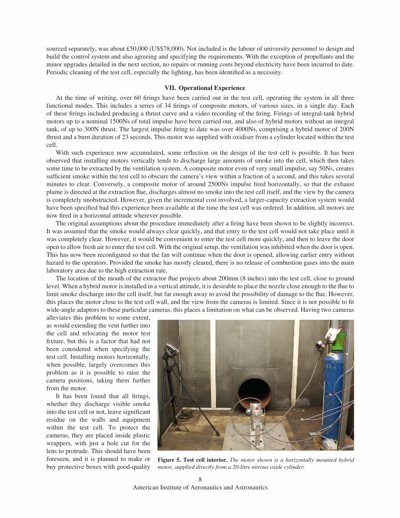
Figure 5. Test cell interior. The motor shown is a horizontally mounted hybrid motor, supplied directly from a 20-litre nitrous oxide cylinder.
9American Institute of Aeronautics and Astronautics
optical windows. However, there may then be a problem with cooling the cameras, and easy access is required, as well as ensuring sufficient space inside to open the LCD display to set up the desired view. (The main TV screen is not visible from inside the test cell.) Although it was not anticipated that the inside to the cell would become hot enough to cause damage to cables, except in the event of fire, it has been found to be necessary to provide some protection for video cables. The fluorescent lights need frequent cleaning, and there has been noticeable accumulation of residues on the walls. Due to the perforated interior surface, this is difficult to remove.
The original setup included two HDMI video cables from the test cell to the TV monitor. The cameras are fitted with a variety of outputs, including mini-HDMI and composite video. The TV has a picture-in-picture capability, if the main image is HDMI and the secondary input is composite video. This provided a convenient oversight for firings of motors with integral oxidiser tanks, as it was possible to monitor both the firing itself in the main view and the tank vent (to see when the tank is full) in the inset image. Thus it was not necessary to re-configure the TV image source during the filling and firing process. However, the mini-HDMI connections proved troublesome, and composite video is now used for both connections. A second TV monitor with a 9-inch screen has been installed to provide the secondary view. Since the cameras record the image in HD on built-in hard drives, there is no loss of quality on the recorded image using composite video feeds.
The initial installation of data lines was quite ad-hoc, and with hindsight this could have been better planned. A screened multi-core cable has now been installed, providing six data lines from within the test cell to the control point.
The vent flue installation terminates in a vertical outlet some 8.5 metres above ground level (see Figure 2). There was some concern about possible flooding of the test cell during rainstorms, and discussion about whether a ‘coolie-hat’ rain cover was required over the outlet. However, it was felt that this would impede flow, and could be retro-fitted if required. A small drain is fitted at the bottom of the flue. Experience over a full year has shown no evidence of water accumulation, and no rainwater has entered the test cell.
There is visible smoke emission from stack during firing, but no observed accretion of fallout nearby, even after firing 34 composite motors of various sizes in one day, as mentioned above. There have been no complaints and no visible residues on the ground nearby; all residues on the ground and adjacent buildings have been cleared by rainwater.
Reference1Chiaverini, M.J. and K.K. Kuo, Fundamentals of Hybrid Rocket Combustion and Propulsion. Vol. 218. 2007:
AIAA.
10American Institute of Aeronautics and Astronautics
Annex A. Control System Schematic and Circuit Diagram
11American Institute of Aeronautics and Astronautics