Embed Size (px)
Citation preview

Design and use of mass-produced aspheres at Kodak
Paul L. Ruben
Aspheric surfaces provide both performance and cost advantages for large-quantity lens production. As-pheres are reviewed from their early application in viewfinders to their use in camera lenses and, most re-
cently, to applications in laser focusing lenses. There are restrictions imposed on the shape or strength ofaspheres by either the manufacturing processes or testing techniques that the designer must recognize.
1. Introduction
The spherical aberration of a condenser lens can bereduced if a hyperbolic rather than a spherical surfaceis used. Recognizing this, Eastman Kodak Co. beganthe pressing of aspheric glass condenser elements.These elements were part of the Kodascope B 16-mmmotion picture projector shown in Fig. 1, which, whenintroduced in 1927, marked the beginning of over ahalf-century of large-volume production of aspheres.
The use of millions of aspheres a year is now an ac-cepted practice. To understand why, several criticalapplications of aspheres will be reviewed. The benefitsthey provide to the design and their preferred methodof testing will be discussed. A description will be givenof the population distribution of aspheres that haveappeared in Kodak's designs. The current manufac-turing limits for mass-produced aspheres will be pre-sented, and, finally, some future applications will beanticipated.
II. Viewfinders
Let us first consider the aspheres found in cameraviewfinders. In 1957, the Signet 30 and Signet 50 cam-eras were introduced, two years later the Automatic 35Camera (Fig. 1). They all had the same finder, a re-versed Galilean-type consisting of a negative objectivelens and a positive eye lens (Fig. 2). Similar finders arefound in today's cameras. There are compelling rea-sons for using aspheres in these finders. In fact, allKodak's still cameras now have aspheres, with goodreason. There are two aberrations which limit a finder's
The author is with Eastman Kodak Company, Rochester, NewYork 14650.
Received 20 December 1984.0003-6935/85/111682-07$02.00/0.C 1985 Optical Society of America.
performance: lateral color and distortion. Both arecontrolled by the negative objective element. To re-duce lateral color, a material of low dispersion is re-quired. To reduce distortion, a high index of refractionis needed. These characteristics are available only incostly rare-earth lanthanum crown glasses. If we in-stead choose acrylic, an inexpensive plastic, it has thelow dispersion which reduces color but also has low re-fractive index, which causes excessive distortion.However, if an asphere is added to the element, distor-tion may be reduced easily. An aspheric curve may bepolished into the mold and thousands of surfaces rep-licated accurately and inexpensively.
How are the aspheres used in viewfinders tested?Recognize that the surface quality required for findersystems is not as stringent as the quality required forphotographic lenses. When the asphere was first usedon the Signet 30 camera, the aspheric mold insert wastested by gauge fit. A brass gauge was cut having thecorrect profile, placed against the mold-insert surface,and, if they matched so that no light could be seenthrough the interface, the insert was thought to besatisfactory. The surfaces of the plastic parts were notmeasured but only tested visually as part of the findersystem. Today testing is more rigorous. During pro-duction start-up, both mold and finished part are testedto within one wavelength with an optical profilometeror specially designed refractive null correctors. Gaugefits remains a backup test technique. Day-to-dayvariability in the parts caused by variations in themolding process is visually inspected for complete fill-ing, then monitored as any plastic lens is, by checkingflange focus. No special concern is needed for asphericvariations.
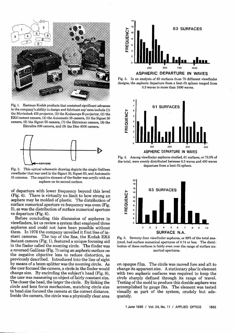
How strong are the aspheres used in viewfinders? Toprovide direction for future manufacturing technologydevelopment, a population survey was made looking forpotential trends.' Among 83 surfaces from 70 differentviewfinder designs, the majority were found to departfrom a best-fit spheres with <550 waves (Fig. 3). Thesesurfaces were distributed very evenly out to 400 waves
1682 APPLIED OPTICS / Vol. 24, No. 11 / 1 June 1985
14
12
0zC:
wU-
83 SURFACES
4
2
0
250 500 750 1000
ASPHERIC DEPARTURE IN WAVESFig. 3. In an analysis of 83 surfaces from 70 different viewfinderdesigns, the aspheric departure from a best-fit sphere ranged from
0.3 waves to more than 1000 waves.
Fig. 1. Eastman Kodak products that contained significant advancesin the company's ability to design and fabricate aspieres include (1)the Moviedeck 425 projector, (2) the Kodascope B projector, (3) theEK6 instant camera, (4) the Automatic 35 camera, (5) the Signet 30camera, (6) the Signet 50 camera, (7) the Ektramax camera, (8) the
Ektralite 500 camera, and (9) the Disc 4000 camera.
(-7 n-3
K -k-- ASPHERE
Fig. 2. This optical schematic drawing depicts the single Galileanviewfinder that was used in the Signet 30, Signet 50, and Automatic35 cameras. The negative element of the finder was acrylic with an
asphere on its second surface.
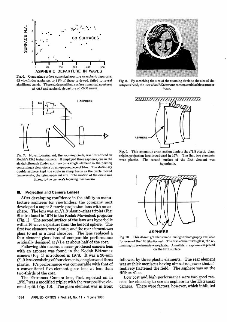
of departure with lower frequency beyond this level(Fig. 4). There is virtually no limit to how strong anasphere may be molded of plastic. The distribution ofsurface numerical aperture vs frequency was even (Fig.5), as was the distribution of surface numerical aperturevs departure (Fig. 6).
Before concluding this discussion of aspheres inviewfinders, let us review a system that employed threeaspheres and could not have been possible withoutthem. In 1976 the company unveiled it first line of in-stant cameras. The top of the line, the Kodak EK6instant camera (Fig. 1), featured a unique focusing aidin the finder called the zooming circle. The finder wasa reversed Galilean (Fig. 7) using an aspheric surface onthe negative objective lens to reduce distortion, aspreviously described. Introduced into the line of sightby means of a beam splitter was the zooming circle. Asthe user focused the camera, a circle in the finder wouldchange size. By encircling the subject's head (Fig. 8),the user was measuring an object of fairly constant size.The closer the head, the larger the circle. By linking thecircle and lens focus mechanism, matching circle sizeto head size focused the camera at the correct distance.Inside the camera, the circle was a physically clear area
8
>- 6
M 4aW 3ccLL 2
61 SURFACES
II I II I Ill ii I i 1I i0 ----- F
100 200 300 400
ASPHERIC DEPARTURE IN WAVES
Fig. 4. Among viewfinder aspheres studied, 61 surfaces, or 73.5% ofthe total, were evenly distributed between 0.3 waves and 400 waves
departure from a best-fit sphere.
2018
16 83 SURFACES14U
Z 12
UJ 10CC 6LL 4
2
0
.1 .2 .3 .4 .5 .6 .7
SURFACE N.A.
. . ..8 .9 1.0
Fig. 5. Seventy-four viewfinder aspheres, or 89% of the total ana-lyzed, had surface numerical apertures of 0.74 or less. The distri-bution of these surfaces is fairly even over the range of surface nu-
merical apertures.
on opaque film. The circle was moved fore and aft tochange its apparent size. A stationary plastic elementwith two aspheric surfaces was required to keep thecircle sharply defined through its range of travel.Testing of the mold to produce this double asphere wasaccomplished by gauge fits. The element was testedvisually as part of the system, crudely but ade-quately.
1 June 1985 / Vol. 24, No. 11 / APPLIED OPTICS 1683
- - - - - - - - - - - .
. . .1~~~~~~~~~~~~~~~~A
.8
z1:-
C',
.6
.4
.2
.0
0%% 00.@@
.0
68 SURFACES
I I I I0 100 200 300
ASPHERIC DEPARTURE
I400 500
IN WAVES
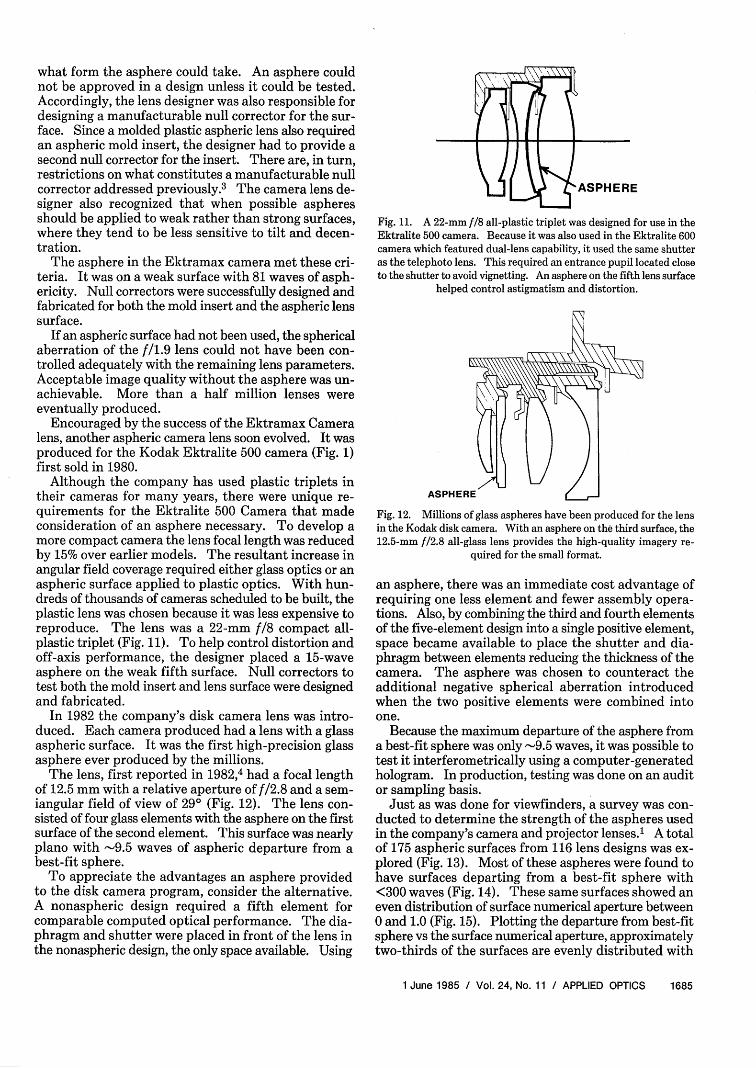
Fig. 6. Comparing surface numerical aperture vs aspheric departure,68 viewfinder aspheres, or 82% of those reviewed, failed to revealsignificant trends. These surfaces all had surface numerical apertures
of <0.8 and aspheric departure of <500 waves.
Fig. 8. By matching the size of the zooming circle to the size of thesubject's head, the user of an EK6 instant camera could achieve proper
focus.
Fig. 7. Novel focusing aid, the zooming circle, was introduced inKodak's EK6 instant camera. It employed three aspheres, one in thestraightthrough finder and two on a single element in the portio;containing a clear circle on an opaque piece of film. The stationarydouble asphere kept the circle in sharp focus as the circle movedtransversely, changing apparent size. The motion of the circle was
linked to the camera's focusing mechanism.
III. Projection and Camera Lenses
After developing confidence in the ability to manu-facture aspheres for viewfinders, the company nextdeveloped a super 8 movie projection lens with an as-phere. The lens was an f/1.8 plastic-glass triplet (Fig.9) introduced in 1974 in the Kodak Moviedeck projector(Fig. 1). The second surface of the lens was hyperbolicwith a 16-wave departure from the best-fit sphere. Thefirst two elements were plastic, and the rear element wasglass to act as a heat absorber. The lens replaced afour-element glass lens of comparable performanceoriginally designed at f/1.4 at about half of the cost.
Following this success, a mass-produced camera lenswith an asphere was found in the Kodak Ektramaxcamera (Fig. 1) introduced in 1978. It was a 26-mmf/1.9 lens consisting of four elements, one glass and threeplastic. It's performance was comparable with that ofa conventional five-element glass lens at less thantwo-thirds of the cost.
The Ektramax Camera lens, first reported on in1979,2 was a modified triplet with the rear positive ele-ment split (Fig. 10). The glass element was in front
Fig. 9. This schematic cross section depicts the f/1.8 plastic-glasstriplet projection lens introduced in 1974. The first two elementswere plastic. The second surface of the first element was
hyperbolic.
UKIASPHERE
Fig. 10. This 26-mm f/1.9 lens made low-light photography availablefor users of the 110 film format. The first element was glass, the re-maining three elements were plastic. A multiterm asphere was placed
on the fifth surface.
followed by three plastic elements. The rear elementwas at thick meniscus having almost no power that ef-fectively flattened the field. The asphere was on thefifth surface.
Low cost and high performance were two good rea-sons for choosing to use an asphere in the Ektramaxcamera. There were factors, however, which inhibited
1684 APPLIED OPTICS / Vol. 24, No. 11 / 1 June 1985
. * @
., .
what form the asphere could take. An asphere couldnot be approved in a design unless it could be tested.Accordingly, the lens designer was also responsible fordesigning a manufacturable null corrector for the sur-face. Since a molded plastic aspheric lens also requiredan aspheric mold insert, the designer had to provide asecond null corrector for the insert. There are, in turn,restrictions on what constitutes a manufacturable nullcorrector addressed previously.3 The camera lens de-signer also recognized that when possible aspheresshould be applied to weak rather than strong surfaces,where they tend to be less sensitive to tilt and decen-tration.
The asphere in the Ektramax camera met these cri-teria. It was on a weak surface with 81 waves of asph-ericity. Null correctors were successfully designed andfabricated for both the mold insert and the aspheric lenssurface.
If an aspheric surface had not been used, the sphericalaberration of the f/1.9 lens could not have been con-trolled adequately with the remaining lens parameters.Acceptable image quality without the asphere was un-achievable. More than a half million lenses wereeventually produced.
Encouraged by the success of the Ektramax Cameralens, another aspheric camera lens soon evolved. It wasproduced for the Kodak Ektralite 500 camera (Fig. 1)first sold in 1980.
Although the company has used plastic triplets intheir cameras for many years, there were unique re-quirements for the Ektralite 500 Camera that madeconsideration of an asphere necessary. To develop amore compact camera the lens focal length was reducedby 15% over earlier models. The resultant increase inangular field coverage required either glass optics or anaspheric surface applied to plastic optics. With hun-dreds of thousands of cameras scheduled to be built, theplastic lens was chosen because it was less expensive toreproduce. The lens was a 22-mm f/8 compact all-plastic triplet (Fig. 11). To help control distortion andoff-axis performance, the designer placed a 15-waveasphere on the weak fifth surface. Null correctors totest both the mold insert and lens surface were designedand fabricated.
In 1982 the company's disk camera lens was intro-duced. Each camera produced had a lens with a glassaspheric surface. It was the first high-precision glassasphere ever produced by the millions.
The lens, first reported in 1982,4 had a focal lengthof 12.5 mm with a relative aperture of f/2.8 and a sem-iangular field of view of 29° (Fig. 12). The lens con-sisted of four glass elements with the asphere on the firstsurface of the second element. This surface was nearlyplano with -9.5 waves of aspheric departure from abest-fit sphere.
To appreciate the advantages an asphere providedto the disk camera program, consider the alternative.A nonaspheric design required a fifth element forcomparable computed optical performance. The dia-phragm and shutter were placed in front of the lens inthe nonaspheric design, the only space available. Using
ASPHERE
Fig. 11. A 22-mm f/18 all-plastic triplet was designed for use in theEktralite 500 camera. Because it was also used in the Ektralite 600camera which featured dual-lens capability, it used the same shutteras the telephoto lens. This required an entrance pupil located closeto the shutter to avoid vignetting. An asphere on the fifth lens surface
helped control astigmatism and distortion.
ASPHERE
Fig. 12. Millions of glass aspheres have been produced for the lensin the Kodak disk camera. With an asphere on the third surface, the12.5-mm f/2.8 all-glass lens provides the high-quality imagery re-
quired for the small format.
an asphere, there was an immediate cost advantage ofrequiring one less element and fewer assembly opera-tions. Also, by combining the third and fourth elementsof the five-element design into a single positive element,space became available to place the shutter and dia-phragm between elements reducing the thickness of thecamera. The asphere was chosen to counteract theadditional negative spherical aberration introducedwhen the two positive elements were combined intoone.
Because the maximum departure of the asphere froma best-fit sphere was only -9.5 waves, it was possible totest it interferometrically using a computer-generatedhologram. In production, testing was done on an auditor sampling basis.
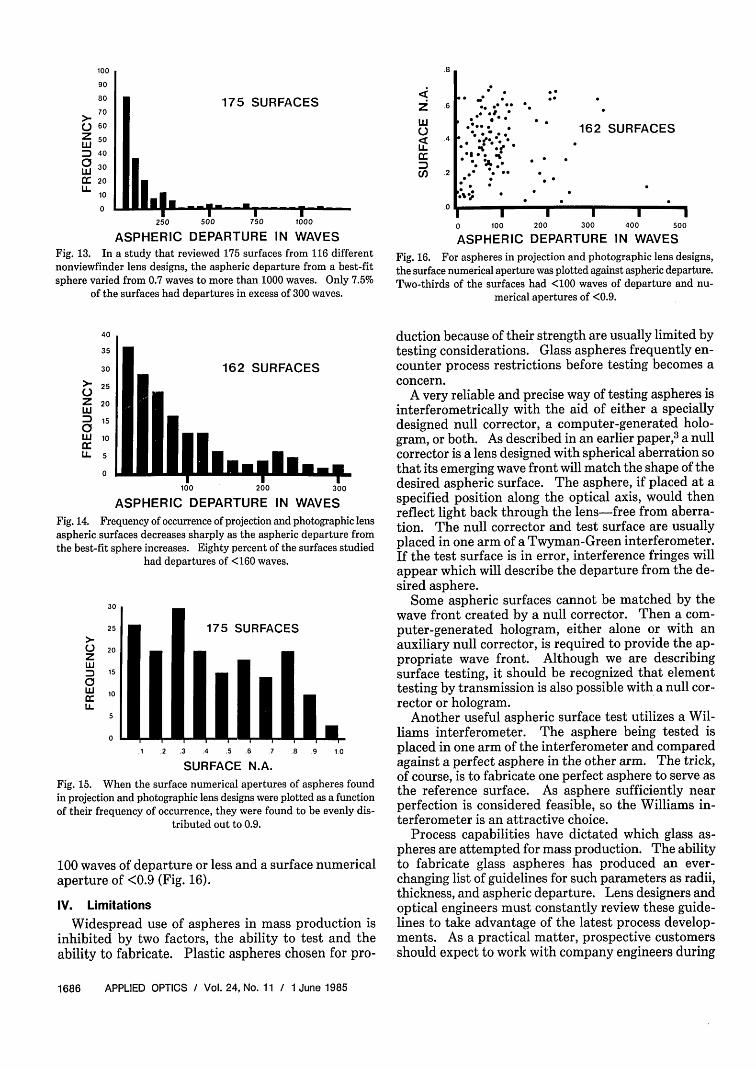
Just as was done for viewfinders, a survey was con-ducted to determine the strength of the aspheres usedin the company's camera and projector lenses.' A totalof 175 aspheric surfaces from 116 lens designs was ex-plored (Fig. 13). Most of these aspheres were found tohave surfaces departing from a best-fit sphere with<300 waves (Fig. 14). These same surfaces showed aneven distribution of surface numerical aperture between0 and 1.0 (Fig. 15). Plotting the departure from best-fitsphere vs the surface numerical aperture, approximatelytwo-thirds of the surfaces are evenly distributed with
1 June 1985 / Vol. 24, No. 11 / APPLIED OPTICS 1685
100
90
80
70
) 60
Zs 50v 40
(:3 30
C: 20
10
0
175 SURFACES
Il.
i:zL1U
CC,
I I
250 500 750 1000
ASPHERIC DEPARTURE IN WAVESFig. 13. In a study that reviewed 175 surfaces from 116 differentnonviewfinder lens designs, the aspheric departure from a best-fitsphere varied from 0.7 waves to more than 1000 waves. Only 7.5%
of the surfaces had departures in excess of 300 waves.
.8
.6
.4
.2
.0
* - .z
: .. .0 .0 0
0 .. 0
0010
005 *0
00
162 SURFACES
0 0 0
sO
0 0
0 0
[ - I I I0 100 200 300
ASPHERIC DEPARTURE
I -400 500
IN WAVES
Fig. 16. For aspheres in projection and photographic lens designs,the surface numerical aperture was plotted against aspheric departure.Two-thirds of the surfaces had <100 waves of departure and nu-
merical apertures of <0.9.
40
35
30
>_ 25
Z 20
D 15
W 10
L50
162 SURFACES
100 200 300
ASPHERIC DEPARTURE IN WAVES
Fig. 14. Frequency of occurrence of projection and photographic lensaspheric surfaces decreases sharply as the aspheric departure fromthe best-fit sphere increases. Eighty percent of the surfaces studied
had departures of <160 waves.
30
25
zw
ciwU-
20
15
10
175 SURFACES
I'll",1 2 .3 .4 .5 .6 7 8 9
SURFACE N.A.1.0
Fig. 15. When the surface numerical apertures of aspheres foundin projection and photographic lens designs were plotted as a functionof their frequency of occurrence, they were found to be evenly dis-
tributed out to 0.9.
100 waves of departure or less and a surface numericalaperture of <0.9 (Fig. 16).
IV. Limitations
Widespread use of aspheres in mass production isinhibited by two factors, the ability to test and theability to fabricate. Plastic aspheres chosen for pro-
duction because of their strength are usually limited bytesting considerations. Glass aspheres frequently en-counter process restrictions before testing becomes aconcern.
A very reliable and precise way of testing aspheres isinterferometrically with the aid of either a speciallydesigned null corrector, a computer-generated holo-gram, or both. As described in an earlier paper, 3 a nullcorrector is a lens designed with spherical aberration sothat its emerging wave front will match the shape of thedesired aspheric surface. The asphere, if placed at aspecified position along the optical axis, would thenreflect light back through the lens-free from aberra-tion. The null corrector and test surface are usuallyplaced in one arm of a Twyman-Green interferometer.If the test surface is in error, interference fringes willappear which will describe the departure from the de-sired asphere.
Some aspheric surfaces cannot be matched by thewave front created by a null corrector. Then a com-puter-generated hologram, either alone or with anauxiliary null corrector, is required to provide the ap-propriate wave front. Although we are describingsurface testing, it should be recognized that elementtesting by transmission is also possible with a null cor-rector or hologram.
Another useful aspheric surface test utilizes a Wil-liams interferometer. The asphere being tested isplaced in one arm of the interferometer and comparedagainst a perfect asphere in the other arm. The trick,of course, is to fabricate one perfect asphere to serve asthe reference surface. As asphere sufficiently nearperfection is considered feasible, so the Williams in-terferometer is an attractive choice.
Process capabilities have dictated which glass as-pheres are attempted for mass production. The abilityto fabricate glass aspheres has produced an ever-changing list of guidelines for such parameters as radii,thickness, and aspheric departure. Lens designers andoptical engineers must constantly review these guide-lines to take advantage of the latest process develop-ments. As a practical matter, prospective customersshould expect to work with company engineers during
1686 APPLIED OPTICS / Vol. 24, No. 11 / 1 June 1985
- - f - -- f . . . -
* .
early design stages to insure that their glass asphericlens will meet these guidelines. They should also beprepared to discuss their systems specifications. Thispermits a timely evaluation of our manufacturingcompetence and tolerance trade-offs.
To appreciate the variety of limitations for not onlythe aspheric surface, but for all parameters of the glassaspheric lens element, these guidelines will now be re-viewed.
Recognize that these capabilities and limitations areflexible and changing for two reasons. First, the processtechnology is expanding rapidly. Glass lenses oncethought impossible to fabricate are now planned forproduction. Second, and most important, the guide-lines are not independent of each other; they are inter-active. Certainly all the limits of the process are notsimultaneously attainable in a single element. Forexample, a surface test possible in one configurationmay be unattainable in another. A strong asphere maybe feasible on a shallow curve but not on a strong radius.While extraordinary results may be achieved in a lab-oratory run they sometimes cannot be economicallyrepeated in production.
Consider first the process limitations on lens diam-eters. Because of an established preference for insertmolding and mounting techniques, diameter control ofthe glass element is not a significant concern. Insertmolding refers to the process of taking an uncenteredelement, aligning both optical surfaces to establish anoptical axis, and then injection molding plastic aroundthe glass. The outer diameter of the plastic mount isthen concentric to the optical axis.
The diameter of the largest glass aspheric lens madein the laboratory exceeds 80 mm. Because large lensesare historically required in smaller quantities, the costadvantage quickly disappears. More expensive tpolingmay be required. Lenses -15 mm in diameter arepreferred, 30 mm possible. Diameter tolerances of+0.10 mm including runout are frequently specified.
As part of a glass aspheric element, radii of <5 mm,convex or concave, and as large as plano, have beensuccessfully fabricated. Radii are limited by eithersurface strength or testing requirements.
Glass element thickness tolerances can be held to±0.015 mm, a difficult tolerance to achieve by conven-tional processes. For negative elements, a minimumcenter thickness of 0.4 is reasonable. A negative ele-ment must have an edge thickness of at least 0.7 mm.The edge thickness of positive elements may be as smallas 0.3 mm. Large elements require proportionallylarger edge thicknesses.
A surface quality, in terms of scratch and dig toler-ances, of 80-50 is adequate for most applications.Smaller-diameter elements or more-critical lenses mayrequire a specification of 60-40 or 40-20 resulting inincreased production costs.
Surface figure has been defined as a tolerance onfringe deviation from nominal, as measured in an in-terferometric test. A four-number specification is useddescribing allowable fringes of power, irregularity(cylindricity), asphericity (aspheric departure at full
aperture), and zonal error (aspheric departure at anintermediate aperture). A test of 3-1-1-1/2 is readilyachievable in production. A test of 2-1/2-1/2-1/4 is pos-sible at increased expense.
More than 50 glasses from a variety of manufacturershave been approved for use in the process for mass-producing glass aspheres. Because of this, customersshould recognize the importance of discussing their glasschoice with company engineers before finalizing theirdesign.
There are several process limitations that are uniqueto the specification of aspheric surfaces. Axial align-ment of an asphere to the center of curvature of theopposing side of the lens (or the axis of another asphere)can be maintained to within 15 min of arc. This angleis defined as between the aspheric axis and the linejoining the center of curvature of the opposing side andthe vertex of the asphere. For small lenses, 10 min ofarc are feasible.
The strength of the aspheric surface is a major con-cern both in fabrication and testing. The stronger thecurve the more difficult the aspheric element is to fab-ricate. The lens designer must attempt to place theasphere on a weak surface, one which has a radius of thebest-fit sphere larger than, say, 75 mm. It is preferredthat the aspheric departure from the best-fit sphere notexceed 25 wavelengths, although a 100-wave departureis possible. It is desired that surface slope, measuredin waves per millimeter, should not exceed 30, althougha maximum of 40 is thought possible. Recognize thataspheric departure and surface slope are primarilyconcerns of metrology rather than process limitations.What limits the ability to measure aspheres? Fre-quently, it depends on the precision of the null correc-tor, the accuracy of the hologram, or the quality of thereference surface.
In the past, it was unlikely that the lens designerheeded all these process and testing limitations. Inpractice, the designer began the effort with a list ofapproved glasses and attempted to place the necessaryasphere on a weak surface. The manufacturing engi-neer, consulting with the process development engineer,determined aspheric fabrication feasibility. Today thedesigner is learning these limitations, understandsthem, and incorporates them in the design. If the de-sign is feasible, work on sample lenses begins. If notfeasible, other design solutions must be sought. If thefeasibility is in question and the designer believes thedesign has strong merit, additional process developmentmay result, or test techniques may be refined further.
V. New Applications
The availability of low-cost glass aspheric elementshas created several evolutionary trends in optical design.Customers, both within Kodak's corporate structureand from other companies, have optical requirementswhich can be enhanced by use of this aspheric tech-nology. It has been obvious for generations that manylenses caiq be simplified by using aspheres. This is atask any competent lens designer can accomplish. Onlynow, with the availability of mass-produced glass as-
1 June 1985 / Vol. 24, No. 11 / APPLIED OPTICS 1687
UA&_1J
ARPHFRF
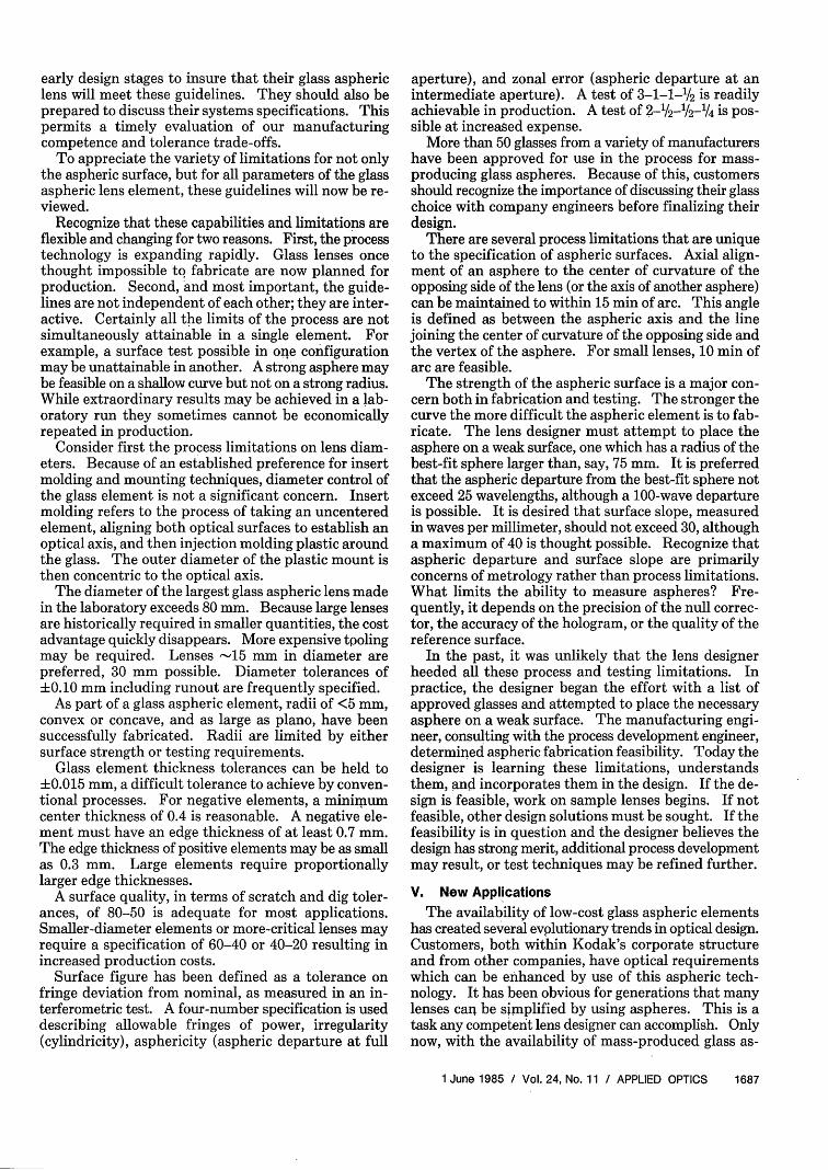
Fig. 17. Three-element lens now found in many audiodisk playersmay soon be replaced by a single-element high-index lens with anaspheric surface. A singlet with a low index of refraction was foundto require a second nonspherical surface to provide satisfactory image
quality.
pheres, does it become practical. Here are some ex-amples, some cases where aspheres may provide tangi-ble benefits.
Just as an asphere reduced the complexity of the diskcamera lens, it can simplify the designs found on today'scompact 35-mm cameras. The asphere represents anadditional degree of freedom to the designer. With it,he can choose to improve performance, reduce thenumber of elements compared to a nonaspheric design,increase the relative aperture without adding elements,or cover a wide angular field, which implies a shorterfocal length and more compact camera. For example,by using an asphere in one design investigation, a fullstop was gained from f/5.6 to f/4 in a 38-mm glass tripletcamera lens. Performance of the two designs wascomparable.
Another attractive application of aspheres is in thedesign and fabrication of digital videodisk and au-diodisk lenses. These lenses focus a laser beam onto anoptical disk. In one application, they work in the nearIR at numerical apertures of 0.45-0.50. Early designsfor this application were reminiscent of microscopeobjectives comprised of two or more elements (Fig. 17).Unlike microscope objectives, these lenses are expectedto become as plentiful as the phonograph needles theyare designed to supplant. They cover very small an-gular fields. Now, by using an asphere, a one-elementdesign is feasible (Fig. 17). Aspheres can control andcorrect an axial wave front over large numerical aper-
tures, so aspheric singlets become the obvious choice toreplace the earlier multielement all-spherical designs.There is another benefit of using aspheres for audiodisklenses. The simpler lenses made possible by asphereshave less mass, an important consideration when de-veloping the tracking mechanism which is part of theassembly.
VI. Conclusion
When designing with aspheres, one must considermore than just where to place the asphere for best imagecorrection. One must consider the practical processlimitations, the fabrication feasibility. Finally, thedesigner must be sensitized to the expected testingtechnique.
Camera lenses and digital audiodisk lenses are justtwo potential applications for mass-produced precisionglass aspheres. The creative designer will identifyothers.
References1. J. E. Van Tassell, "Distribution of Aspheric Surface Characteris-
tics"; internal communication (1984).2. L. R. Estelle, "Design, Performance, and Selection of Kodak's
'Ektramax' Lens," Proc. Soc. Photo-Opt. Instrum. Eng. 193, 211(1979).
3. P. L. Ruben, "Refractive Null Correctors for Aspheric Surfaces,"Appl. Opt. 15, 3080 (1976).
4. D. DeJager, "Objective Lens for the Kodak Disc Camera," pre-sented at SPSE International Symposium, 22 Mar. 1983.
0
1688 APPLIED OPTICS / Vol. 24, No. 11 / 1 June 1985
l l l
0 l l
HTT__�


![[XLS] · Web viewwms project management wms implementation service kodak imaglnk scnr 900s_ kodak imaglnk scnr 900d_ kodak imaglnk semiauto fdr kodak imaglnk patch rdr ac](https://img.pdfslide.us/doc/110x75/5ab639c47f8b9a86428d8207/xls-viewwms-project-management-wms-implementation-service-kodak-imaglnk-scnr-900s.jpg)


![Mid-spatial frequency errors of mass-produced aspheres · Chapter 7]. A direct method of analysis is to generate a Power Spectral Density (PSD) plot and set tolerances on this plot.4](https://img.pdfslide.us/doc/110x75/5f2abf8145d875006c75a02d/mid-spatial-frequency-errors-of-mass-produced-aspheres-chapter-7-a-direct-method.jpg)