Embed Size (px)
Citation preview
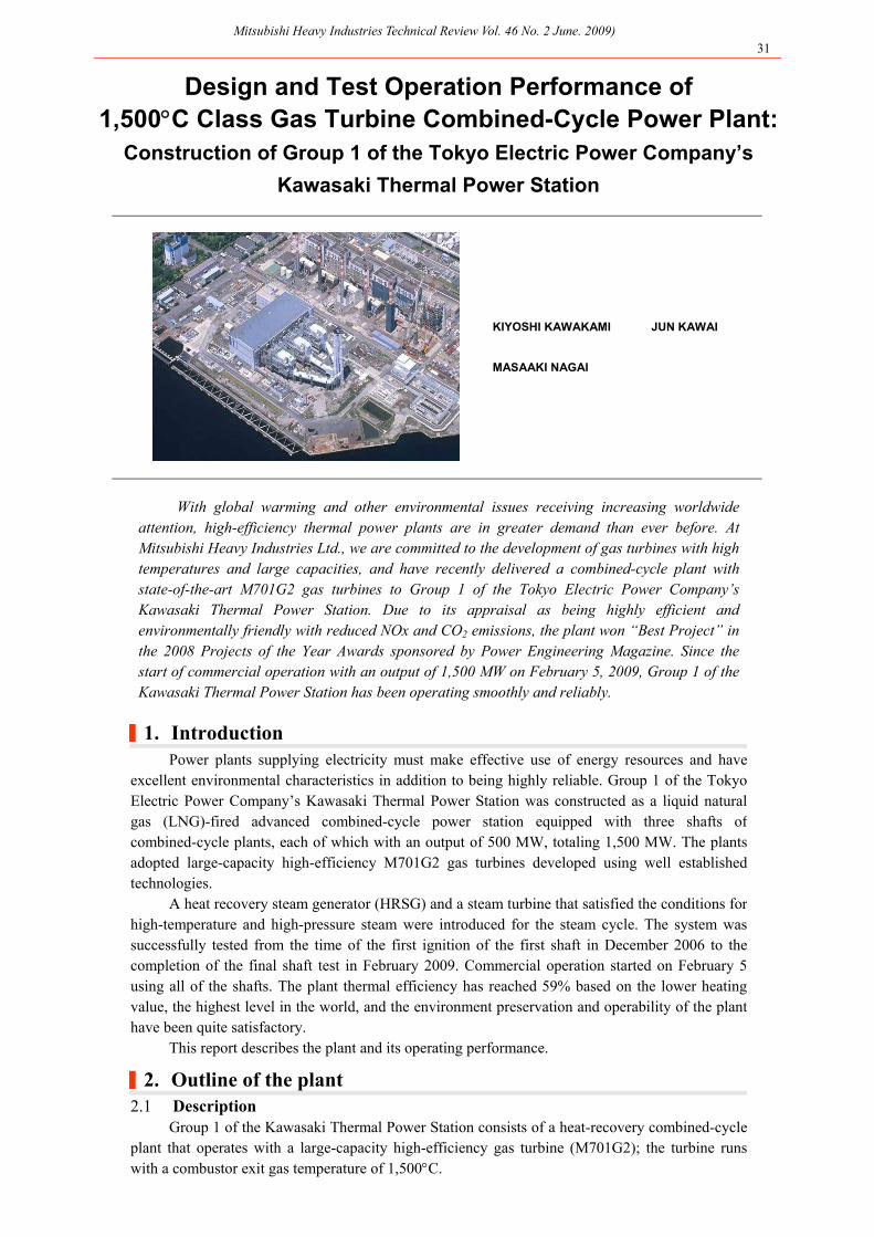
Mitsubishi Heavy Industries Technical Review Vol. 46 No. 2 June. 2009) 31
Design and Test Operation Performance of 1,500C Class Gas Turbine Combined-Cycle Power Plant:
Construction of Group 1 of the Tokyo Electric Power Company’s
Kawasaki Thermal Power Station
KIYOSHI KAWAKAMI JUN KAWAI
MASAAKI NAGAI
With global warming and other environmental issues receiving increasing worldwide attention, high-efficiency thermal power plants are in greater demand than ever before. At Mitsubishi Heavy Industries Ltd., we are committed to the development of gas turbines with high temperatures and large capacities, and have recently delivered a combined-cycle plant with state-of-the-art M701G2 gas turbines to Group 1 of the Tokyo Electric Power Company’s Kawasaki Thermal Power Station. Due to its appraisal as being highly efficient and environmentally friendly with reduced NOx and CO2 emissions, the plant won “Best Project” in the 2008 Projects of the Year Awards sponsored by Power Engineering Magazine. Since the start of commercial operation with an output of 1,500 MW on February 5, 2009, Group 1 of the Kawasaki Thermal Power Station has been operating smoothly and reliably.
|1. Introduction
Power plants supplying electricity must make effective use of energy resources and have excellent environmental characteristics in addition to being highly reliable. Group 1 of the Tokyo Electric Power Company’s Kawasaki Thermal Power Station was constructed as a liquid natural gas (LNG)-fired advanced combined-cycle power station equipped with three shafts of combined-cycle plants, each of which with an output of 500 MW, totaling 1,500 MW. The plants adopted large-capacity high-efficiency M701G2 gas turbines developed using well established technologies.
A heat recovery steam generator (HRSG) and a steam turbine that satisfied the conditions for high-temperature and high-pressure steam were introduced for the steam cycle. The system was successfully tested from the time of the first ignition of the first shaft in December 2006 to the completion of the final shaft test in February 2009. Commercial operation started on February 5 using all of the shafts. The plant thermal efficiency has reached 59% based on the lower heating value, the highest level in the world, and the environment preservation and operability of the plant have been quite satisfactory.
This report describes the plant and its operating performance.
|2. Outline of the plant 2.1 Description
Group 1 of the Kawasaki Thermal Power Station consists of a heat-recovery combined-cycle plant that operates with a large-capacity high-efficiency gas turbine (M701G2); the turbine runs with a combustor exit gas temperature of 1,500C.
Mitsubishi Heavy Industries Technical Review Vol. 46 No. 2 June. 2009) 32
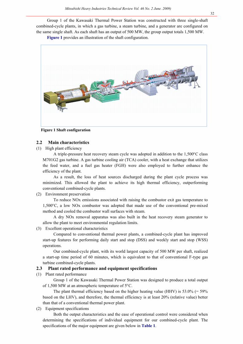
Group 1 of the Kawasaki Thermal Power Station was constructed with three single-shaft combined-cycle plants, in which a gas turbine, a steam turbine, and a generator are configured on the same single shaft. As each shaft has an output of 500 MW, the group output totals 1,500 MW.
Figure 1 provides an illustration of the shaft configuration.
Figure 1 Shaft configuration
2.2 Main characteristics (1) High plant efficiency
A triple-pressure heat recovery steam cycle was adopted in addition to the 1,500C class M701G2 gas turbine. A gas turbine cooling air (TCA) cooler, with a heat exchange that utilizes the feed water, and a fuel gas heater (FGH) were also employed to further enhance the efficiency of the plant.
As a result, the loss of heat sources discharged during the plant cycle process was minimized. This allowed the plant to achieve its high thermal efficiency, outperforming conventional combined-cycle plants.
(2) Environment preservation To reduce NOx emissions associated with raising the combustor exit gas temperature to
1,500C, a low NOx combustor was adopted that made use of the conventional pre-mixed method and cooled the combustor wall surfaces with steam.
A dry NOx removal apparatus was also built in the heat recovery steam generator to allow the plant to meet environmental regulation limits.
(3) Excellent operational characteristics Compared to conventional thermal power plants, a combined-cycle plant has improved
start-up features for performing daily start and stop (DSS) and weekly start and stop (WSS) operations.
Our combined-cycle plant, with its world largest capacity of 500 MW per shaft, realized a start-up time period of 60 minutes, which is equivalent to that of conventional F-type gas turbine combined-cycle plants.
2.3 Plant rated performance and equipment specifications (1) Plant rated performance
Group 1 of the Kawasaki Thermal Power Station was designed to produce a total output of 1,500 MW at an atmospheric temperature of 5C.
The plant thermal efficiency based on the higher heating value (HHV) is 53.0% (= 59% based on the LHV), and therefore, the thermal efficiency is at least 20% (relative value) better than that of a conventional thermal power plant.
(2) Equipment specifications Both the output characteristics and the ease of operational control were considered when
determining the specifications of individual equipment for our combined-cycle plant. The specifications of the major equipment are given below in Table 1.
Mitsubishi Heavy Industries Technical Review Vol. 46 No. 2 June. 2009) 33
Table 1 Main equipment specifications
No. of units Three No. of units Three
Type Single-shaft
open-cycle type (M701G2 type)
Type
Comb-shaped double- flow
exhaust reheat mixed-pressure condensing type
Fuel LNG Evaporated gas (TC2F - 35.4)
Output
167,000 kW
Output 333,000 kW (at atmospheric
Inlet pressure (HP)
12.78 MPa
temperature of 5oC) (IP) 3.37 MPa Inlet temperature 1,500 oC (LP) 0.4 MPa
Gas turbine
Rotation speed 3,000 rpm Inlet temperature No. of units Three (HP) 564 oC
Type
Triple pressure reheat natural
circulation type heat recovery steam
(IP) (LP)
Condenser
vacuum
565 oC 273 oC
50.7 hPa
generator Evaporation
Steam turbine
Rotation speed 3,000 rpm
(HP) 360 t/h No. of units Three
(IP) (LP)
Steam pressure
(HP) (IP)
100 t/h 70 t/h
13.18 MPa 4.52 MPa
Type
Horizontal-shaft
tubular rotary field type three-phase
synchronous generator
(LP) 0.45 MPa Capacity 558,000 kVA
Steam
temperature (HP)
567 oC
Voltage
Power factor
16,200 V
90% (lag)
(IP) 277 oC Frequency 50 Hz
Heat recovery
steam generator
(LP) 276 oC
Generator
Rotation speed 3,000 rpm
|3. Characteristics of the main equipment 3.1 Gas turbines
In 2002, a loading test was conducted at the factory for the M701G2 gas turbine to verify its performance and characteristics and confirm its high reliability.
Steam cooling technology was adopted for the combustor of the M701G2 gas turbine. Making the most of the cooling steam by sending the cooling steam through the path of the turbine blade ring allowed us to control the tip clearance of the turbine unit. Warming up the side of the turbine blade ring at start-up allowed the clearance to be widened, whereas cooling it during load operation enabled us to optimize the clearance. Furthermore, blades and vanes with advanced aerodynamic and cooling performance were introduced to the first stage, while the exhaust diffuser was improved to diminish the aerodynamic loss. All of these features were designed to upgrade the turbine performance.
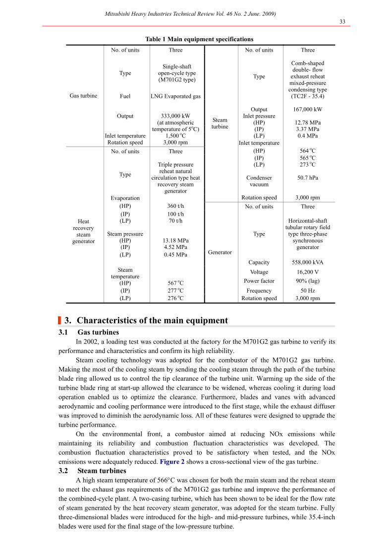
On the environmental front, a combustor aimed at reducing NOx emissions while maintaining its reliability and combustion fluctuation characteristics was developed. The combustion fluctuation characteristics proved to be satisfactory when tested, and the NOxemissions were adequately reduced. Figure 2 shows a cross-sectional view of the gas turbine. 3.2 Steam turbines
A high steam temperature of 566C was chosen for both the main steam and the reheat steam to meet the exhaust gas requirements of the M701G2 gas turbine and improve the performance of the combined-cycle plant. A two-casing turbine, which has been shown to be ideal for the flow rate of steam generated by the heat recovery steam generator, was adopted for the steam turbine. Fully three-dimensional blades were introduced for the high- and mid-pressure turbines, while 35.4-inch blades were used for the final stage of the low-pressure turbine.
Mitsubishi Heavy Industries Technical Review Vol. 46 No. 2 June. 2009) 34
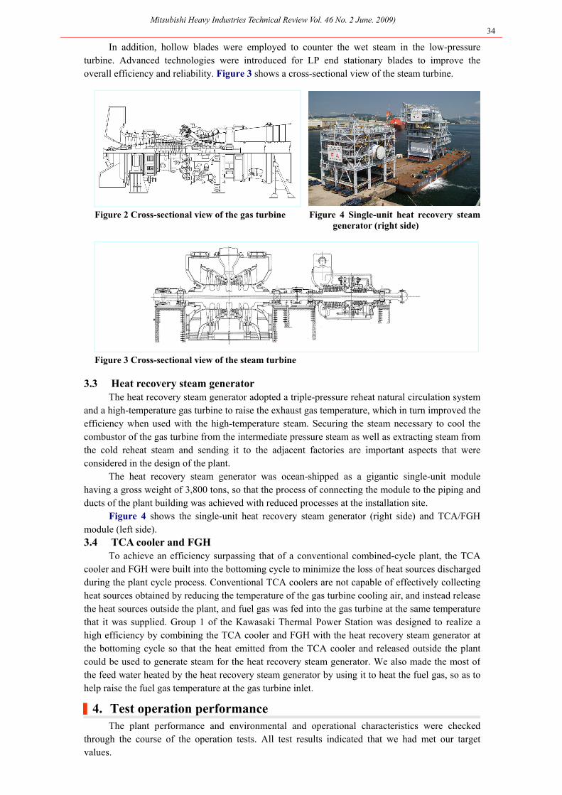
In addition, hollow blades were employed to counter the wet steam in the low-pressure turbine. Advanced technologies were introduced for LP end stationary blades to improve the overall efficiency and reliability. Figure 3 shows a cross-sectional view of the steam turbine.
Figure 2 Cross-sectional view of the gas turbine Figure 4 Single-unit heat recovery steamgenerator (right side)
Figure 3 Cross-sectional view of the steam turbine
3.3 Heat recovery steam generator The heat recovery steam generator adopted a triple-pressure reheat natural circulation system
and a high-temperature gas turbine to raise the exhaust gas temperature, which in turn improved the efficiency when used with the high-temperature steam. Securing the steam necessary to cool the combustor of the gas turbine from the intermediate pressure steam as well as extracting steam from the cold reheat steam and sending it to the adjacent factories are important aspects that were considered in the design of the plant.
The heat recovery steam generator was ocean-shipped as a gigantic single-unit module having a gross weight of 3,800 tons, so that the process of connecting the module to the piping and ducts of the plant building was achieved with reduced processes at the installation site.
Figure 4 shows the single-unit heat recovery steam generator (right side) and TCA/FGH module (left side). 3.4 TCA cooler and FGH
To achieve an efficiency surpassing that of a conventional combined-cycle plant, the TCA cooler and FGH were built into the bottoming cycle to minimize the loss of heat sources discharged during the plant cycle process. Conventional TCA coolers are not capable of effectively collecting heat sources obtained by reducing the temperature of the gas turbine cooling air, and instead release the heat sources outside the plant, and fuel gas was fed into the gas turbine at the same temperature that it was supplied. Group 1 of the Kawasaki Thermal Power Station was designed to realize a high efficiency by combining the TCA cooler and FGH with the heat recovery steam generator at the bottoming cycle so that the heat emitted from the TCA cooler and released outside the plant could be used to generate steam for the heat recovery steam generator. We also made the most of the feed water heated by the heat recovery steam generator by using it to heat the fuel gas, so as to help raise the fuel gas temperature at the gas turbine inlet.
|4. Test operation performance The plant performance and environmental and operational characteristics were checked
through the course of the operation tests. All test results indicated that we had met our target values.
Mitsubishi Heavy Industries Technical Review Vol. 46 No. 2 June. 2009) 35
4.1 Plant performance Table 2 gives the measured performance of the plant. The rated output of 500 MW could be
ensured at an atmospheric temperature of 5C and higher. The measured thermal efficiency exceeded the target value of 53.0% (higher heating value), which approximately corresponds to a lower heating value of 59%.
Table 2 Measured plant performance
Measured values
Output 479.4MW (atmospheric temperature at 22.45oC)
509.7MW (atmospheric temperature at 5 oC equivalent)
Thermal efficiency 53.54% (higher heating value) 59.18% (lower heating value)
4.2 Environmental characteristics
The NOX controlling technology using the steam-cooling type low NOX combustor and the dry type de-NOX system provided safe operation with reduced NOX emissions. The concentration of NOX emitted from the stacks was lower than the environmental regulation limit of 5 ppm (O2=16% equivalent). 4.3 Operational characteristics
Multiple tests were performed to verify the operational characteristics of the plant during the tests. These included the automatic plant start and stop function test, dispatching power control (DPC) and automatic frequency control (AFC), and run back tests. The test results demonstrated that the plant could be operated as designed.
|5. Conclusion Group 1 of Tokyo Electric Power Company’s Kawasaki Thermal Power Station was
constructed as a combined-cycle plant with leading-edge technologies, and has been operating successfully as expected. The sophistication of the plant and the environmental measures introduced through technological innovation are noteworthy. In particular, the development of the gas turbine was a technological marvel. The development of the entire plant system, including the steam cycle, meets the current efficiency and environmental requirements.
The valuable results obtained from this plant make a great contribution toward the planning of future plants, both in terms of capacity and efficiency. It is our belief that the Group 1 combined-cycle plant of the Kawasaki Thermal Power Station will provide a great service for local communities and society in general by operating as an environmentally friendly plant, providing reliable and stable electricity, and providing steam to local factories.
Reference 1. Tsukagoshi, K. et al., Operating Status of Uprating Gas Turbines and Future Trend of Gas Turbine
Development, Mitsubishi Heavy Industries Technical Review Vol. 44 No. 4 (2007)
Authors
Kiyoshi Kawakami Manager Quality Assurance Department Takasago Machinery Works
Jun Kawai Manager Takasago Power Plant Construction Department Power Systems Plant Engineering & Construction Division Power Systems Headquarters
Masaaki Nagai Manager Boiler Engineering Department Power Systems Headquarters


![872091 - B35D & B40D Operation and Test Manual[1]](https://img.pdfslide.us/doc/110x75/547f7a53b4af9fda158b59d1/872091-b35d-b40d-operation-and-test-manual1.jpg)