Embed Size (px)
Citation preview

RESEARCH Open Access
Design and pilot validation of A-gear: anovel wearable dynamic arm supportPeter N Kooren1*, Alje G Dunning2,3, Mariska M H P Janssen4, Joan Lobo-Prat5, Bart F J M Koopman5,Micha I Paalman1, Imelda J M de Groot4 and Just L Herder2,6
Abstract
Background: Persons suffering from progressive muscular weakness, like those with Duchenne muscular dystrophy(DMD), gradually lose the ability to stand, walk and to use their arms. This hinders them from performing dailyactivities, social participation and being independent. Wheelchairs are used to overcome the loss of walking.However, there are currently few efficient functional substitutes to support the arms. Arm supports or robotic armscan be mounted to wheelchairs to aid in arm motion, but they are quite visible (stigmatizing), and limited in theirpossibilities due to their fixation to the wheelchair. The users prefer inconspicuous arm supports that arecomfortable to wear and easy to control.
Methods: In this paper the design, characterization, and pilot validation of a passive arm support prototype, whichis worn on the body, is presented. The A-gear runs along the body from the contact surface between seat andupper legs via torso and upper arm to the forearm. Freedom of motion is accomplished by mechanical joints,which are nearly aligned with the human joints. The system compensates for the arm weight, using elastic bandsfor static balance, in every position of the arm. As opposed to existing devices, the proposed kinematic structureallows trunk motion and requires fewer links and less joint space without compromising balancing precision.The functional prototype has been validated in three DMD patients, using 3D motion analysis.
Results: Measurements have shown increased arm performance when the subjects were wearing the prototype.Upward and forward movements were easier to perform. The arm support is easy to put on and remove. Moreover,the device felt comfortable for the subjects. However, downward movements were more difficult, and the patientswould prefer the device to be even more inconspicuous.
Conclusion: The A-gear prototype is a step towards inconspicuousness and therefore well-received dynamicarm supports for people with muscular weakness.
BackgroundDuchenne Muscular Dystrophy (DMD) is the most com-mon genetic neuromuscular disorder diagnosed in child-hood, affecting approximately one in every 5000 livemale births [1]. Due to the dystrophin gene being lo-cated on the X-chromosome, DMD primarily affectsboys. DMD is caused by a mutation in the gene that en-codes for dystrophin and results in progressive loss ofmuscle strength and muscle tissue [2].People suffering from progressive muscular weakness,
like those with DMD, can lose the ability to walk and
stand and the ability to control the function of theirarms. This hinders them from performing daily activ-ities, participating socially and being independent. Awheelchair can overcome the loss of walking. However,for the loss of arm function there seem to be few efficientand well adopted aids. Currently used aids are poweredand non-powered arm supports and robot arms mountedon the wheelchair. Overviews are given by van der Heide[3], Dunning [4] and Mahoney [5]. These overviews showfor example the Armon (MicroGravity, NL), the WREX(Jaeco, US) and the Darwing (Focal, NL). The majority ofthe existing arm supports is mounted on the wheelchair,
* Correspondence: [email protected] of Physics and Medical Technology, VU Medical Center,Amsterdam, The NetherlandsFull list of author information is available at the end of the article
J N E R JOURNAL OF NEUROENGINEERINGAND REHABILITATION
© 2015 Kooren et al. Open Access This article is distributed under the terms of the Creative Commons Attribution 4.0International License (http://creativecommons.org/licenses/by/4.0/), which permits unrestricted use, distribution, andreproduction in any medium, provided you give appropriate credit to the original author(s) and the source, provide a link tothe Creative Commons license, and indicate if changes were made. The Creative Commons Public Domain Dedication waiver(http://creativecommons.org/publicdomain/zero/1.0/) applies to the data made available in this article, unless otherwise stated.
Kooren et al. Journal of NeuroEngineering and Rehabilitation (2015) 12:83 DOI 10.1186/s12984-015-0072-y
which limits the range of motion. Moreover, existing sup-ports are quite visible [6] and can be experienced asstigmatizing.In the case of boys with DMD, due to improved med-
ical care and technical possibilities, life expectancy hasincreased rapidly [7, 8]. As a consequence, most of themwill have no functional arm movements for more thanhalf of their life, if unsupported.A survey, in which 350 persons with DMD partici-
pated worldwide, stated that only a small percentage(8.5 %) of DMD patient uses an arm support. Inaddition, this survey describes which ADL tasks aremost important for DMD patients [9]. Essential activitiesto perform with an arm support are eating, drinking, useof a phone and computers, personal hygiene, physicalcontact with others and dressing. Persons with DMDwill use an arm support seated only, since they are in awheelchair at the time they need an arm support.Wishes with respect to the arm support, apart from in-creased ability, are inconspicuousness, intuitive control,easy donning and comfort [6, 10]. The arm support pref-erably would be worn underneath clothing, e.g. sweaterand pants.Therefore, the objective of this study was to develop,
and pilot test in persons with DMD, a novel wearablearm support. This paper describes a prototype design foran inconspicuous arm support for activities of daily liv-ing (ADL tasks) and presents the characterization andvalidation of this device.The support is called A-gear, where the A stands for
ability. The A-gear is a piece of equipment increasingthe user’s ability.
MethodsDesign methodTo generate design concepts the main function ofthe device, namely to support arm motion, is splitinto sub functions [11]. The sub functions are: 1)generating force to compensate for the weight of thearm, 2) transferring reaction forces through the armsupport and 3) transferring forces to and from theuser. First, solutions were generated for these subfunctions by a team of medical specialists, technicalspecialists and a person with DMD, resulting in amorphological overview. By systematically combiningthe solutions for the sub functions about 700 pos-sible concepts could be conceived. Seven conceptswere intuitively selected from the morphologicaloverview and elaborated to realistically dimensionedsketches. These drawings helped to evaluate themwithin the same team of specialists and choose theoptimal concept to detail and manufacture. “Optimal”meant scoring best on the combination of these cri-teria: low balancing error, close to the body, technical
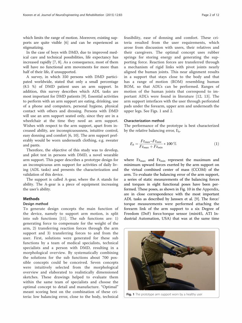
feasibility, ease of donning and comfort. These cri-teria resulted from the user requirements, whicharose from discussion with users, their relatives andtheir caregivers. The optimal concept uses rubbersprings for storing energy and generating the sup-porting force. Reaction forces are transferred througha mechanism of rigid links with pivot joints nearlyaligned the human joints. This near alignment resultsin a support that stays close to the body and thathas a range of motion (ROM) resembling humanROM, so that ADL’s can be performed. Ranges ofmotion of the human joints that correspond to im-portant ADL’s were found in literature [12, 13]. Thearm support interfaces with the user through perforatedpads under the forearm, upper arm and underneath theupper legs. See Figs. 1 and 2.
Characterization methodThe performance of the prototype is best characterizedby the relative balancing error, Eb.
Eb ¼ Fzmax−Fzmin
Fzmax þ Fzmin� 100% ð1Þ
where Fzmax and Fzmin represent the maximum andminimum upward forces exerted by the arm support onthe virtual combined center of mass (CCOM) of thearm. To evaluate the balancing error of the arm support,a series of static measurements of the balancing forcesand torques in eight functional poses have been per-formed. These poses, as shown in Fig. 10 in the Appendix,are in close correspondence with the most importantADL tasks as described by Janssen et al. [9]. The force/torque measurements were performed attaching theforearm link of the arm support to a six Degree ofFreedom (DoF) force/torque sensor (mini45, ATI In-dustrial Automation, USA) that was at the same time
Fig. 1 The prototype arm support worn by a healthy user
Kooren et al. Journal of NeuroEngineering and Rehabilitation (2015) 12:83 Page 2 of 12

mounted to a position controlled robotic manipulator(UR5, Universal Robots, Denmark) that served asground (Fig. 3). By switching the manipulator to acompliant state while repositioning manually, internalstresses between arm support and manipulator wereminimized. Three measurements were performed ateach position. A change of the force/torque sensorcoordinate system was applied to the force/torquevectors in order to express the measurements at thearm coordinate system (ψa), which is located at theCCOM of the arm. Furthermore, a rotation of thiscoordinate system was applied in order to express
the force/torque signals in the global coordinate sys-tem (ψg).
Pilot validation methodFor the validation of the prototype, three DMD patientswith early functional limitations in their arms (Brookescale 2 and 3. People in scale 2 can raise their arm abovethe head only by flexing the elbow. People in Brookescale 3 cannot raise their arm above the head, but canraise a filled glass to the mouth) and one healthy subject,participated in testing the prototype (see Table 1 andFig. 4). The healthy subject was included to establish
Fig. 2 a A schematical representation of the kinematical architecture of the device. b A picture of the prototype.
Fig. 3 Setup for analyzing the balancing error. The balancing error of the prototype was verified by connecting it with a robot arm equipped with a sixDoF load sensor
Kooren et al. Journal of NeuroEngineering and Rehabilitation (2015) 12:83 Page 3 of 12

reference values for the performance with and withoutthe prototype. Participants were included through theRadboud UMC outpatient clinic and by advertising thestudy on the website of a Dutch patient organization.This study was approved by the medical ethical commit-tee Arnhem-Nijmegen, the Netherlands, and subjectsand their parents gave informed consent before partici-pating in the study.All participants performed standardized single joint
movements of shoulder and elbow (shoulder flexion,shoulder abduction, shoulder horizontal adduction,shoulder internal and external rotation and elbowflexion) and ADL tasks (extracted from the shoulderand elbow dimension of the “Performance of theUpper Limb (PUL) Scale” [14], which is used tomeasure upper limb performance in people withDMD) with and without wearing the prototype. Ex-amples of the tasks are stacking cans, picking upcoins and tearing paper. 3D motion analysis (VICONmotion analysis system (Oxford Metrics, Oxford, UK))was performed to gain insight in the ROM of thesubject, by tracking the position of the hand markerduring the single joint movements. The motion datawas processed with Matlab (Mathworks, Natick, USA)coded algorithms. In addition, all participants filledout a questionnaire to gain more insight in
‘functionality ‘comfort ‘aesthetics ‘safety ‘compatibility’and ‘donning and doffing’.
Design resultsKinematic architectureThe arm support is supporting the forearm at theCCOM. In 3D space, the forearm of a user has sixDoF’s. An assumption is made that a forearm sup-ported by a curved interface can rotate within theskin when the user pro- or supinates the hand.Therefore, the mechanism of the arm support shouldprovide the other five DoF’s. Intentionally, the armsupport is only connected with the upper legs andforearm. In this manner, intermediate parts do nothave to move synchronously with the human bodyand the joints do not have to be aligned perfectly.Still, near alignment is required, for the arm supportto stay close to the body. An interface is placedagainst the upper arm, but this interface only sup-ports the arm when the forearm is pointing upward.Without this interface the forearm would slip fromthe support when it is in vertical orientation with thehand upward.Per arm, five revolute joints in series are used as
kinematic chain. The first one is next to the hip. Thesecond, third and fourth joint are pointing approxi-mately towards the shoulder’s rotation point, and thefifth is next to the elbow (see Fig. 2). Revolute jointsare simple and can be implemented with little fric-tion. The advantage of having three joints in theshoulder region is that the arm support stays on theouter side of the arm. Therefore, the user can havedirect contact with his arms on a table, and approacha table without bumping parts of the arm supportagainst it.Arc lengths between joint 2 and 3 and between 3
and 4 (Fig. 2) are chosen to be 56° such that theROM of the human shoulder complex [15] is largelycovered. The radius of the arcs is 70 mm. In thissize, there is no interference of the arcs with thewheelchair’s back- and headrest. Revolute joint 2 istilted 10° posteriorly and 10° medially, to complywith the human shoulder motion, and also to makespace for elastic bands. During arm motion, no sin-gularities are encountered in the shoulder joint. TheROM of the individual revolute joints is limited withend stops.The links between the joints, which are implemented
as tubes, are custom made for the intended user.
Interfacing with userThe user is sitting on five pads (two below eachupper leg, one against the user’s bottom). The padsare flexible and can be formed to the body. The pads
Table 1 Data of subjects in the pilot validation study
Subject Disease Age [yrs.] Sex Weight [kg] Brooke scale
1 DMD 15 M 63 2
2 DMD 14 M 70 3
3 DMD 17 M 82 3
4 Healthy 31 M 77 1
Fig. 4 Boy with Duchenne testing the prototype, while wearingelectromyography and motion capturing devices
Kooren et al. Journal of NeuroEngineering and Rehabilitation (2015) 12:83 Page 4 of 12
are clicked on metal tubes, which fixate their shape.The forearm link is attached to the users arm with apad and a Velcro band. The upper arm pad is only toprevent the forearm from slipping from its pad whenpointing upward. The pad against the forearm is thedominant contact point.Since the user is sitting in the mechanism and it is
only attached to the upper and lower arm, the completemechanism is easy to put on and take off. Moreover,since the structure runs parallel to the users arm andtrunk, it has the opportunity to be worn underneathclothing.
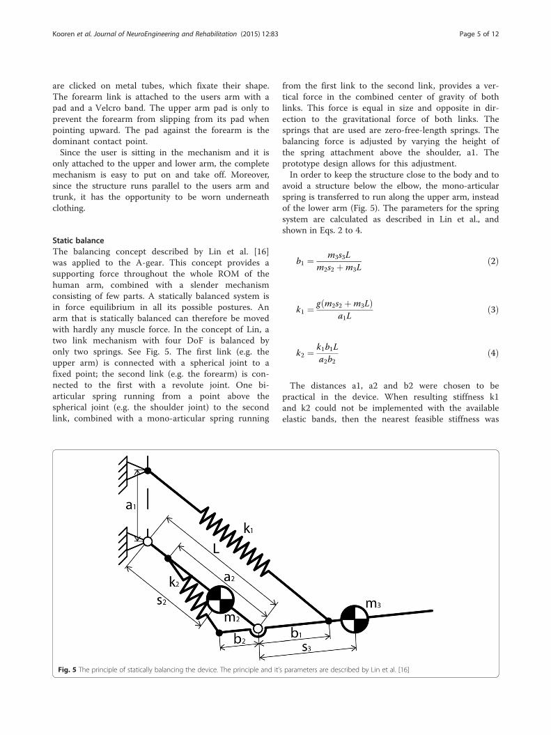
Static balanceThe balancing concept described by Lin et al. [16]was applied to the A-gear. This concept provides asupporting force throughout the whole ROM of thehuman arm, combined with a slender mechanismconsisting of few parts. A statically balanced system isin force equilibrium in all its possible postures. Anarm that is statically balanced can therefore be movedwith hardly any muscle force. In the concept of Lin, atwo link mechanism with four DoF is balanced byonly two springs. See Fig. 5. The first link (e.g. theupper arm) is connected with a spherical joint to afixed point; the second link (e.g. the forearm) is con-nected to the first with a revolute joint. One bi-articular spring running from a point above thespherical joint (e.g. the shoulder joint) to the secondlink, combined with a mono-articular spring running
from the first link to the second link, provides a ver-tical force in the combined center of gravity of bothlinks. This force is equal in size and opposite in dir-ection to the gravitational force of both links. Thesprings that are used are zero-free-length springs. Thebalancing force is adjusted by varying the height ofthe spring attachment above the shoulder, a1. Theprototype design allows for this adjustment.In order to keep the structure close to the body and to
avoid a structure below the elbow, the mono-articularspring is transferred to run along the upper arm, insteadof the lower arm (Fig. 5). The parameters for the springsystem are calculated as described in Lin et al., andshown in Eqs. 2 to 4.
b1 ¼ m3s3Lm2s2 þm3L
ð2Þ
k1 ¼ g m2s2 þm3Lð Þa1L
ð3Þ
k2 ¼ k1b1La2b2
ð4Þ
The distances a1, a2 and b2 were chosen to bepractical in the device. When resulting stiffness k1and k2 could not be implemented with the availableelastic bands, then the nearest feasible stiffness was
Fig. 5 The principle of statically balancing the device. The principle and it’s parameters are described by Lin et al. [16]
Kooren et al. Journal of NeuroEngineering and Rehabilitation (2015) 12:83 Page 5 of 12

chosen and a1 and b2 adjusted to satisfy the balan-cing criteria.The mass of the human upper arm is divided to the
shoulder and the elbow according to the position ofthe center of mass of the upper arm. This means thatin the equations from Lin et al., to calculate the pa-rameters of the spring system, m2 is only the mass ofthe link of the prototype along the upper arm. Thecombined mass m3 is the sum of the mass of theforearm, a part of the mass of the upper arm and themass of the link of the prototype along the forearm(Eq. 5). According to this mass distribution the centerof combined mass on the forearm is calculated usingEq. 6.
m3 ¼ mFA þmUA⋅s2Lþmlink3 ð5Þ
s3 ¼ mFA⋅sFA þmlink3
m3ð6Þ
Rubber bands are chosen above metal springs, sincea certain mass or volume of rubber that is axiallystretched can store more elastic energy than the samemass or volume of metal in a helical spring [17].Consequently, the arm support will be more light-weight and slender. To find springs matching the
characteristics needed to balance the arm, we havecompared the characteristics of different elastic bands.The rubber bands used in the arm support (SyntheticPolyisoprene, Jaeco Orthopedic, USA), almost behavelike a zero-free-length spring between 150 % and400 % strain, as is shown in Fig. 6. To verify whetherthe zero-free-length reference line is indeed related tothe force/displacement curve, the intraclass correl-ation coefficient (Two-way mixed, average measure,ICC(3,k)) was calculated. The ICC between the refer-ence line and the average force was 0.997, meaningthat the spring characteristics match the zero-free-length reference line almost perfectly. This makesthese elastic bands very suitable for this application.The stiffness can be varied stepwise by changing theamount of elastic bands.
PrototypeThe manufactured prototype is shown in Figs. 1and 2. The straight and bent tubes are made ofsteel, for convenient bending and welding. In futureproducts, the tubes could be made of a compositematerial for weight reduction. A tube was designed,within the limits of the tube bending process, whichfollows the human shape as close as possible inorder to be inconspicuous and fit between user andthe wheelchair’s backrest.
Fig. 6 Characteristic of the rubber band with the zero-free-length spring behavior. In blue the mean and standard deviation of the force/displacementcurve during elongation of the rubber band are shown. In red the same curve is shown during relaxation of the elastic band. The black dotted line showsthe zero-free-length reference line
Kooren et al. Journal of NeuroEngineering and Rehabilitation (2015) 12:83 Page 6 of 12
To interface with the user, polymer pads that havepadding and perforation were used for comfort purposes(Fig. 2). In existing orthotics, this type of pads has beenexperienced as comfortable.
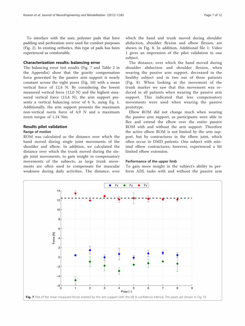
Characterization results: balancing errorThe balancing error test results (Fig. 7 and Table 2 inthe Appendix) show that the gravity compensationforce generated by the passive arm support is nearlyconstant across the eight poses (Fig. 10) with a meanvertical force of 12,4 N. By considering the lowestmeasured vertical force (12,0 N) and the highest mea-sured vertical force (13,4 N), the arm support pre-sents a vertical balancing error of 6 %, using Eq. 1.Additionally, the arm support presents the maximumnon-vertical norm force of 4,9 N and a maximumnorm torque of 1.14 Nm.
Results pilot validationRange of motionROM was calculated as the distance over which thehand moved during single joint movements of theshoulder and elbow. In addition, we calculated thedistance over which the trunk moved during the sin-gle joint movements, to gain insight in compensatorymovements of the subjects, as large trunk move-ments are often used to compensate for muscularweakness during daily activities. The distance, over
which the hand and trunk moved during shoulderabduction, shoulder flexion and elbow flexion, areshown in Fig. 8. In addition, Additional file 1: Video1 gives an impression of the pilot validation in onesubject.The distance, over which the hand moved during
shoulder abduction and shoulder flexion, whenwearing the passive arm support, decreased in thehealthy subject and in two out of three patients(Fig. 8). When looking at the movement of thetrunk marker we saw that this movement was re-duced in all patients when wearing the passive armsupport. This indicated that less compensatorymovements were used when wearing the passiveprototype.Elbow ROM did not change much when wearing
the passive arm support, as participants were able toflex and extend the elbow over the entire passiveROM with and without the arm support. Thereforethe active elbow ROM is not limited by the arm sup-port, but by contractures in the elbow joint, whichoften occur in DMD patients. One subject with min-imal elbow contractures, however, experienced a bitlimited elbow extension.
Performance of the upper limbTo gain more insight in the subject’s ability to per-form ADL tasks with and without the passive arm
Fig. 7 Plot of the mean measured forces exerted by the arm support with the 68 % confidence interval. The poses are shown in Fig. 10
Kooren et al. Journal of NeuroEngineering and Rehabilitation (2015) 12:83 Page 7 of 12

support, the participants performed tasks from theshoulder and elbow dimension of the PUL scale[14]. The healthy subject and the subject withBrooke 2 performed the items from the shoulderand elbow dimension (dimension is meant in theclinical sense not in the technical) of the PUL. Thesubjects with Brooke 3 only performed the elbowdimension, since they were not able to execute theitems from the shoulder dimension without theprototype. Figure 9 shows the PUL scores per di-mension as percentage of the maximal possiblescore on that dimension. The PUL scores of all pa-tients improved for the elbow dimension, meaningthat patients were able to perform more tasks andused less compensatory movements when wearingthe arm support. The PUL score of the shoulder di-mension of the healthy subject reduced, due to thelimited shoulder ROM of the passive arm support.
QuestionnaireThe questionnaire consisted of question regarding: ‘func-tionality’, ‘comfort’, ‘aesthetics’, ‘safety’, ‘compatibility’ and‘donning and doffing’.
Upwards and forward movements are experiencedeasier while downward movements are experiencedmore difficult. On average, participants felt a littlelimited in their ROM by the prototype. However, thesubjects stated that they were all still able to per-form important activities, such as drinking andreaching for objects. In addition, the participantsstated that the prototype fitted well and felt comfort-able. However, sometimes the shoulder parts of theprototype interfere with the shoulder of the user orthe wheelchair and sometimes the arm part collidedwith the table or wheelchair. The lower arm inter-face felt comfortable to all participants. All partici-pants stated that the arm support could not be wornunderneath clothing. The opinions about the looksof the prototype differed between participants. Oneparticipant stated that he thought the visible parts ofthe prototype looked nice, while other participantsstated that the appearance of the prototype shouldstill be improved before they were willing to wear itin daily life. On the level of safety all patients weresatisfied. The arm was steadily attached in the armsupport. Furthermore, the prototype did not make
Fig. 8 Range of motion displayed as the distance covered by the hand and trunk during single joint movements (shoulder abduction, shoulderflexion and elbow flexion), displayed for four different subjects with and without the passive arm support
Kooren et al. Journal of NeuroEngineering and Rehabilitation (2015) 12:83 Page 8 of 12

unintended movements and was stable. One partici-pant felt his skin getting pinched near the shoulder,while other participants did not have this experience.The prototype did not inhibit breathing. Donningthe prototype was experienced harder than doffingthe prototype, although most participants thoughtthat the time it took to put on and off the prototypewas reasonable.Overall, all patients stated that they would like to
use such an arm support in daily life, however theywould also like to see some adaptations to preventcollisions with the body and surroundings and onthe looks of the prototype.
DiscussionThe results of the study show a prototype designthat can be worn close to the body and permitsmore trunk movements, a quantification of the bal-ancing performance and outcome of tests in whichpeople with DMD used the arm support.In comparison with current arm supports, the A-
gear is placed more naturally to the body. The de-vice runs parallel to the arm, trunk and upper legsof the user and has mechanical joints nearly alignedwith the human joints. The design makes motionmore intuitive, free of singularities and the authorsbelieve that, by optimizing the concept, the devicewill fit underneath clothing.The vertical force generated by the arm support is
largely constant across the measured poses. However, a
balancing error of 6 % was found and the results doshow non-vertical forces and torques in the system.There may be several reasons for the error and un-intended forces and torques. Firstly, the springscompensate for the intrinsic mass of the device, butdo not compensate for the fact that the mass isnext to the human arm instead of in line with thehuman arm. To compensate this offset the balan-cing theory should be extended. Secondly, errorsmay arise from interaction forces between user andsupport on other locations than the forearm, e.g.the upper arm pad. This effect could be reduced bya forearm interface shape that prevents the forearmfrom slipping out and removing the upper arm pad.One-hundred percent weight compensation is not
always preferred by patients. One of the patientswanted less supporting force, which felt more com-fortable to him.In the pilot validation, all patients showed a functional
improvement on the elbow dimension of the PUL scale.The improvement indicates that they were able to per-form more items, or that they had to use less compensa-tory strategies, when wearing the passive arm support.The distance over which the trunk moved, which is ameasure for the amount of compensatory movementsused, also reduced in all patients, when they were usingthe passive arm support. The reduction of compensatorymovements is very important, as compensatory move-ment consumes a lot of energy and therefore they re-strict the endurance to perform daily activities.
0
10
20
30
40
50
60
70
80
90
100
P1Shoulder
dimension
H1Shoulder
dimension
P1Elbow
dimension
P2Elbow
dimension
P3Elbow
dimension
H1Elbow
dimension
Per
cen
tag
e o
f m
axim
al p
oss
ible
sco
re (
%)
PUL scores per dimension
Without arm support
With arm support
Fig. 9 Performance of the Upper Limb scores per dimension as percentage of the maximal possible score of the dimension. P1, P2 and P3 areDMD patients, H1 is the healthy subject
Kooren et al. Journal of NeuroEngineering and Rehabilitation (2015) 12:83 Page 9 of 12
The distance over which the hand marker movedreduced in three out of four subjects, when wearingthe passive arm support. For the healthy subjectand the patient with Brooke scale 2 (P1), thisdecrease in ROM was expected, because of thekinematics of the arm support, which restrictedshoulder abduction beyond 90° and shoulder flexionbeyond 120°. Since both the healthy subject and P1were able to move the arm over the entire ROMwithout arm support, they were restricted in theirshoulder movements by the passive arm support.For the patients with Brooke scale 3, we saw thatthe distance over which the hand moved during sin-gle joint movements increased in one patient (P2)and decreased in another patient (P3), when wear-ing the passive arm support. We would haveexpected an increase of the distance in both pa-tients with Brooke scale 3. One possible explanationof a reduction of the distance, over which the handwas moved in P3, might lie in the amount of com-pensatory movements that were used by this pa-tient, when he was not wearing the arm support. Byusing compensatory movements this patient wasable to move the hand, but the movements wereuncontrolled and not very functional, as can beseen by the lower PUL score without the arm sup-port. Consequently a large movement of the handmarker was seen. When this patient used the pas-sive arm support less compensatory movementswere used and much more control over the move-ment could be executed, therefore his functionalscore improved.From the items as mentioned as essential activities
to perform with an arm support (eating, drinking, useof a phone and computers, personal hygiene, physicalcontact with others and dressing) the vast majoritycan be met with the prototype according to the tests.The healthy subject already reached the maximal scoreof the elbow dimension without wearing the passivearm support and he was still able to do this with thepassive arm support.The results of the questionnaire indicated that pa-
tients were able to perform some activities withmore ease, while other activities were more difficult.Some comments were expressed regarding comfortand safety, which should be improved in a futurepassive arm support.Overall the passive arm support was especially
beneficial for patients with a Brooke scale of 3,those that are not able to lift their hands abovetheir head without support. These patients showedfunctional improvements and indicated that armmovements became less fatiguing. All patients statedthat they would like to use such an arm support in
daily life; however, some aspects of the arm supportwould still require improvement.The practical implementation and clinical tests
taught us which aspects need further developmentor should be included in a wearable arm support forpeople with muscular weakness. Firstly, the spacebetween the wheelchair’s arm supports is limited forthe device. These arm supports are placed close tothe user for sideway stability. Next to the hips theorthosis should be very slender to fit in the seat.Secondly, supporting only one arm causes a skewposture, since arm weight hanging from one shoul-der is reduced. Two sided support is preferred.Thirdly, the possibility to lean forward is much ap-preciated. Lastly, the arm support preferably doesnot run between arm and trunk and does not addconsiderable volume underneath the forearm andelbow. Components between arm and trunk make ituncomfortable to have the arms relaxed along thetrunk. Structures below the elbow clash with table-tops when moving over them.
ConclusionsIn this paper, a design of a passive dynamic armsupport for persons with reduced functional abil-ities of their arms, more specifically, for peoplewith Duchenne, is proposed. The architecture ofthe device follows human anatomy. According tothe authors knowledge, the A-gear was the first de-vice that applied the principle for static balancing,proposed by Lin [16], in orthotics. Parameters werefound so that elastics bands and attachment pointsstay close to the user. A step forward has beenmade to develop an inconspicuous arm support thatcan be worn underneath clothing.Three persons with DMD tested the prototype and
all showed an increased PUL score with less com-pensatory movements, compared with not using thesupport. The trunk has more freedom to move aswell, due to hinges next to the hips.Subjective feedback of the users tells that the arm
support is easy to put on. Arm movements forwardand up become easier, movements downward andtasks on a table top are still difficult. The userswould prefer the device even more inconspicuous.The users felt wearing the device was comfortable,among others because it offers free breathing.The shown prototype is a step towards well
adopted dynamics arm supports that improve partici-pation in society, that make people with muscularweakness more independent and more able to per-form important activities in daily life.
Kooren et al. Journal of NeuroEngineering and Rehabilitation (2015) 12:83 Page 10 of 12

Appendix
Fig. 10 Forces exerted by the arm support displayed in context of the user. Moreover, the figure shows the poses, in which balancing error ofthe arm support was determined
Table 2 An overview of the results of the balancing error tests
Pose 1 Pose 2 Pose 3 Pose 4 Pose 5 Pose 6 Pose 7 Pose 8
Tx (Nm) 0,79 (0,18) −0,59 (0,21) −0,36 (0,69) −0,09 (0,09) −0,48 (0,06) −0,75 (0,23) −0,48 (0,03) −0,07 (0,58)
Ty (Nm) −0,56 (0,14) −0,38 (0,02) −0,73 (0,12) 0,40 (0,36) −0,21 (0,29) 0,51 (0,29) 0,43 (0,03) −0,88 (0,04)
Tz (Nm) 0,60 (0,04) 0,04 (0,46) 0,16 (0,36) 0,43 (0,35) 0,14 (0,04) 0,04 (0,04) 0,15 (0,01) −0,02 (0,08)
Fx (N) 0,38 (0,14) 1,45 (0,82) −0,06 (0,55) 0,65 (1,23) −0,12 (0,40) 0,77 (0,70) 0,88 (0,40) 0,41 (0,46)
Fy (N) −4,88 (0,79) −0,98 (1,05) −1,81 (1,11) −2,93 (0,71) −1,61 (0,13) −1,30 (0,87) −0,93 (0,09) −1,39 (1,65)
Fz (N) 13,44 (0,51) 11,95 (0,04) 12,85 (0,25) 12,15 (0,66) 12,42 (1,19) 12,29 (0,65) 12,19 (0,23) 12,13 (0,39)
|T| (Nm) 1,14 (0,16) 0,81 (0,11) 1,05 (0,08) 0,75 (0,09) 0,59 (0,10) 0,92 (0,34) 0,66 (0,04) 1,00 (0,04)
|F| (N) 14,32 (0,46) 12,13 (0,23) 13,03 (0,05) 13,68 (1,46) 12,53 (1,19) 12,47 (0,86) 12,27 (0,25) 12,30 (0,49)
The forces and torques are exerted by the arm support (Fig. 3). The table gives the mean and 1 SD of the X, Y and Z forces and torques, expressed in the inertialframe, together with the mean and 1 SD of the corresponding norms. The poses of the measurements are shown in Fig. 10
Kooren et al. Journal of NeuroEngineering and Rehabilitation (2015) 12:83 Page 11 of 12

Additional file
Additional file 1: Video 1. An impression of the second person(P2) with DMD, testing the new arm support. (MP4 81207 kb)
AbbreviationsDoF: Degree of freedom; PUL: Performance of the upper limb;DMD: Duchenne muscular dystrophy; ADL: Activity of daily living;CCOM: Combined center of mass; SD: Standard deviation.
Competing interestsThe authors declare that they have no competing interests.
Authors’ contributionsPK: conceptual design, manufacturing, validating, writing: abstract, intro,methods, design partially, discussion, conclusions. GD: conceptual design,validation, writing: design and discussion partially. MJ: Validation, writing:validation. JL: Characterization: writing: characterization BQ. BK: Project leader,conceptual idea, supervision, feedback on article. MP: Supervision,conceptual design, feedback on article. IdG: Supervision, article modification.JH: Supervision, conceptual design, article outline, feedback.
AcknowledgementsThe authors gratefully acknowledge Arjen Bergsma for a prior conceptual designand Arno Stienen, Edsko Hekman and Jaap Harlaar for their advice during thedesign and validation. They also show gratitude to Danny Koops, Sjoerd te Slaaand Thijs Zwinnen of the department Physics and Medical Technology of the VUmedical center for their contributions to the prototypes. Nauzef Mahmood isthanked for critically reading the manuscript. Moreover, the Dutch TechnologyFoundation STW*, UPPMD, Prinses Beatrix Spierfonds, Spieren voor Spieren,Johanna Kinderfonds, Kinderrevalidatiefonds Adriaanstichting, FocalMeditech, OIM Orthopedie, Ambroise and Parent Project MuscularDystrophy are thanked for financial support for the project and theirfeedback during biannual meetings. Finally, but not least, the patients thatparticipated in the validation study, are gratefully acknowledged for theirefforts, shared thoughts and enthusiasm.* which is part of the Dutch Organization for Scientific Research (NWO), and whichis partly funded by the Ministry of Economic Affairs. Project Number: 11832.
Author details1Department of Physics and Medical Technology, VU Medical Center,Amsterdam, The Netherlands. 2Department of Precision & MicrosystemsEngineering, Delft University of Technology, Delft, The Netherlands.3Department of Biomechanical Engineering, Delft University of Technology,Delft, The Netherlands. 4Department of Rehabilitation, Donders Center forNeuroscience, Radboud University Medical Center, Nijmegen, TheNetherlands. 5Department of Biomechanical Engineering, University ofTwente, Enschede, The Netherlands. 6Department of Mechanical Automation,University of Twente, Enschede, The Netherlands.
Received: 1 June 2015 Accepted: 2 September 2015
References1. Mendell JR, Shilling C, Leslie ND, Flanigan KM, al-Dahhak R, Gastier-Foster J,
et al. Evidence-based path to newborn screening for Duchenne musculardystrophy. Ann Neurol. 2012;71(3):304–13.
2. Emery AE. Population frequencies of inherited neuromuscular diseases–aworld survey. Neuromuscul Disord. Jan. 1991;1(1):19–29.
3. Van der Heide L a, van Ninhuijs B, Bergsma A, Gelderblom GJ, van der Pijl DJ, deWitte LP. An overview and categorization of dynamic arm supports for peoplewith decreased arm function. Prosthet Orthot Int. 2013;38(4):287–302.
4. Dunning AG, Herder JL. A review of assistive devices for arm balancing.United States: IEEE International Conference on Rehabilitation Robotics;2013. See: http://www.ncbi.nlm.nih.gov/pubmed/24187302
5. Mahoney RM. Robotic Products for Rehabilitation: Status and Strategy Table1: Rehabilitation Robotics Commercial Endeavors.
6. Rahman T, Sample W, Seliktar R, Alexander M, Scavina M. A body-poweredfunctional upper limb orthosis. no. December. 675–680, 2000.
7. Eagle M, Bourke J, Bullock R, Gibson M, Mehta J, Giddings D, et al. ManagingDuchenne muscular dystrophy {\textendash} The additive effect of spinal surgeryand home nocturnal ventilation in improving survival. Neuromuscul Disord.2007;17(6):470–5.
8. Kohler M, Clarenbach CF, Bahler C, Brack T, Russi EW, Bloch KE. Disability andsurvival in Duchenne muscular dystrophy. J Neurol Neurosurg Psychiatry. Mar.2009;80(3):320–5.
9. Janssen MMHP, Bergsma A, Geurts ACH, de Groot IJM. Patterns of decline inupper limb function of boys and men with DMD: an international survey.J Neurol. Jul. 2014;261(7):1269–88.
10. van der Heide L a, Gelderblom GJ, de Witte LP. Effects and effectiveness ofdynamic arm supports: a technical review. Am J Phys Med Rehabil.2015;94(1):44–62.
11. Pahl G, Beitz W, Feldhusen J, Grote K-H. Engineering Design: A SystematicApproach. London: Springer Science & Business Media; 2007. 638. See:http://www.springer.com/us/book/9781846283185
12. Aizawa J, Masuda T, Koyama T, Nakamaru K, Isozaki K, Okawa A, et al. Three-dimensional motion of the upper extremity joints during various activitiesof daily living. J Biomech. Nov. 2010;43(15):2915–22.
13. Romilly DP, Anglin C, Gosine RG, Hershler C, Raschke SU. A Functional TaskAnalysis and Motion Simulation for the Development of a Powered Upper-Limb Orthosis. IEEE Transactions on Rehabilitation Engineering; vol. 2, no. 3,1994. See: http://ieeexplore.ieee.org/xpl/articleDetails.jsp?url=http%3A%2F%2Fieeexplore.ieee.org%2Fstamp%2Fstamp.jsp%3Ftp%3D%26arnumber%3D331561%26userType%3Dinst&denyReason=-134&arnumber=331561&productsMatched=null&userType=inst
14. Mayhew A, Mazzone ES, Eagle M, Duong T, Ash M, Decostre V, et al.Development of the Performance of the Upper Limb module for Duchennemuscular dystrophy. Dev Med Child Neurol. Nov. 2013;55(11):1038–45.
15. Rosen J, Perry JC, Manning N, Burns S, Hannaford B. The human arm kinematicsand dynamics during daily activities - Toward a 7 DOF upper limb poweredexoskeleton. 2005 Int Conf Adv Robot ICAR’05, Proc. 2005;2005:532–9.
16. Lin P-Y, Shieh W-B, Chen D-Z. A theoretical study of weight-balancedmechanisms for design of spring assistive mobile arm support (MAS). MechMach Theory. 2013;61:156–67.
17. Cool JC. Werktuigkundige Systemen. 3rd ed. Delft: Delft Academic Press;1992. p. 344.
Submit your next manuscript to BioMed Centraland take full advantage of:
• Convenient online submission
• Thorough peer review
• No space constraints or color figure charges
• Immediate publication on acceptance
• Inclusion in PubMed, CAS, Scopus and Google Scholar
• Research which is freely available for redistribution
Submit your manuscript at www.biomedcentral.com/submit
Kooren et al. Journal of NeuroEngineering and Rehabilitation (2015) 12:83 Page 12 of 12