Embed Size (px)
Citation preview
Progress In Electromagnetics Research, Vol. 122, 327–339, 2012
DESIGN AND OPTIMIZATION OF LOW RCS PATCHANTENNAS BASED ON A GENETIC ALGORITHM
X. Zhu, W. Shao*, J.-L. Li, and Y. Dong
School of Physical Electronics, University of Electronic Science andTechnology of China (UESTC), Chengdu 610054, China
Abstract—In this article, a genetic algorithm (GA) is employedto the design of low radar cross section (RCS) patch antennas.Combined with the high frequency simulation software (HFSS) forantenna simulations, the GA performs the optimization of geometricparameters. In order to reduce the RCS while holding thesatisfying radiation performance of antennas, the radiation modeland scattering model are respectively calculated. The combinationof proportionate selection and elitist model for the selection strategyis used to speed up the convergence of the GA. Two-point crossoveris adopted to accelerate the converging speed and results in more fitindividuals. Moreover, the whole design procedure is auto-controlledby programming the VBScript in the HFSS. Two examples of low RCSslot antennas are provided to verify the accuracy and efficiency of theproposed method.
1. INTRODUCTION
An antenna, which acts as a strong electromagnetic scatterer, is oftenthe main contributor to the overall radar cross section (RCS) of astealth aircraft [1–5]. Because of the basic radiation function of anantenna, the shaping method is one of the most effective methodsfor antenna RCS reduction [6]. In [7], circle and rectangular slots onthe antenna patch cut off surface currents of high-order modes. [4, 8]introduce some types of fractal slots on an antenna patch to obtain thelow backscattering. Frequency selective surface (FSS) structures arealso presented to reduce RCS of reflect-array antennas [9, 10]. Lumpedresistances which are soldered between the patches of mushroom-like high-impedance surface (HIGP) lead to a significant reduction
Received 7 October 2011, Accepted 17 November 2011, Scheduled 22 November 2011* Corresponding author: Wei Shao ([email protected]).
328 Zhu et al.
of the RCS of waveguide slot antennas [11]. The reduction of RCSin a wide frequency bandwidth is achievable by using dispersivemetamaterials [12]. However, those parameters are difficult to get dueto the simultaneous consideration on antenna radiation and scattering.
In view of the complexity of the low RCS antenna design,antenna geometric parameters are optimized with the differentialevolution algorithm (DEA) to realize the RCS reduction [13]. Basedon the separate DEA optimization for radiation and scattering, theindividuals of bad radiation performance avoid the unnecessary RCSsimulation of the method of moment (MoM). However, the final fitnesscalculations for each generation involve both of the radiation andscattering factors, which maybe lead to an inefficient solution.
Genetic algorithm (GA) optimizers are robust and stochasticsearch methods modeled on the principles and concepts of natureselection and evolution. The GA has been widely used for solvingcomplex electromagnetic (EM) problems [14–17]. Varied antennas,such as monopole antennas [18, 19], Yagi antennas [20, 21], patchantennas [22–25] and array antennas [26–29] are designed for certainkinds of radiating target by GA optimization.
In this article, the lower RCS patch antennas are designed andoptimized by combining the GA with a finite element method (FEM)based tool (high frequency simulation software, HFSS). The GA andHFSS are responsible for the optimization and simulation of low RCSantennas, respectively. An auto-controlled calculation is programmedbased on the VBScript language in HFSS.
For rectangular patch antennas, the location and size of slots areoptimized to obtain satisfying radiation and scattering performances.When applying the GA to low RCS antenna design, it is frequentlynecessary to solve EM problems with FEM-based HFSS hundreds oftimes, until the solution converges to a global extremum. In general,the EM simulations for antennas can be time consuming. Therefore,the amount of computation for each call of the EM solver by the GAneeds to be reduced. The fitness value is calculated separately for theradiation and scattering targets in order to speed up the convergence.The combination of proportionate selection and elitist model as theselection strategy not only accelerates the converging speed but alsokeeps the global research. For the crossover strategy, the two-pointcrossover is utilized to hold the important generation modes effectively.
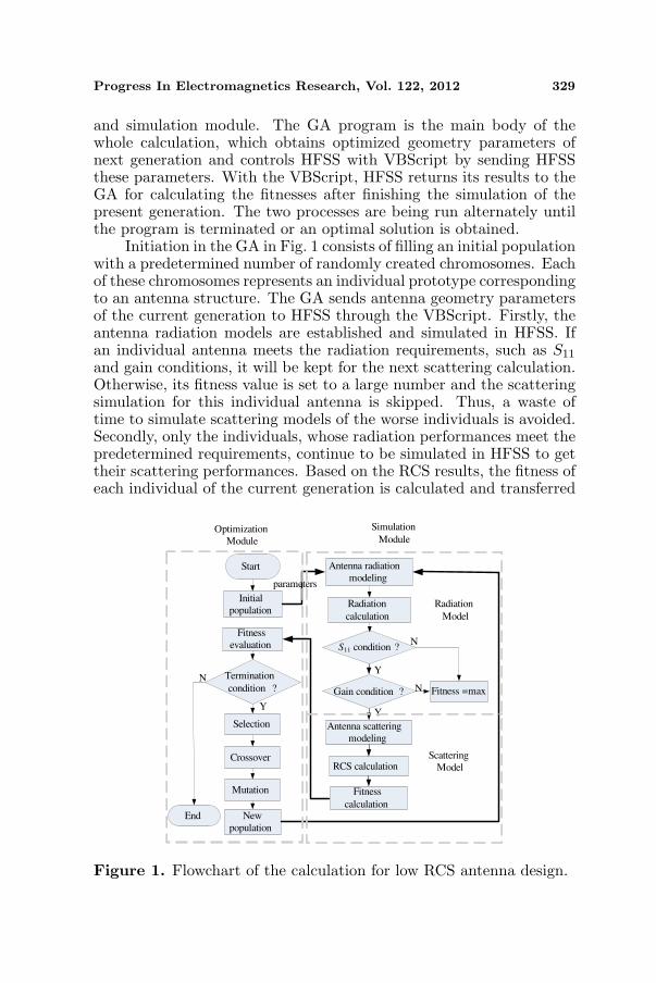
2. GA OPTIMIZATION FOR LOW RCS ANTENNAS
The flowchart of the whole calculation for low RCS antenna designis depicted in Fig. 1, which is made up of the optimization module
Progress In Electromagnetics Research, Vol. 122, 2012 329
and simulation module. The GA program is the main body of thewhole calculation, which obtains optimized geometry parameters ofnext generation and controls HFSS with VBScript by sending HFSSthese parameters. With the VBScript, HFSS returns its results to theGA for calculating the fitnesses after finishing the simulation of thepresent generation. The two processes are being run alternately untilthe program is terminated or an optimal solution is obtained.
Initiation in the GA in Fig. 1 consists of filling an initial populationwith a predetermined number of randomly created chromosomes. Eachof these chromosomes represents an individual prototype correspondingto an antenna structure. The GA sends antenna geometry parametersof the current generation to HFSS through the VBScript. Firstly, theantenna radiation models are established and simulated in HFSS. Ifan individual antenna meets the radiation requirements, such as S11
and gain conditions, it will be kept for the next scattering calculation.Otherwise, its fitness value is set to a large number and the scatteringsimulation for this individual antenna is skipped. Thus, a waste oftime to simulate scattering models of the worse individuals is avoided.Secondly, only the individuals, whose radiation performances meet thepredetermined requirements, continue to be simulated in HFSS to gettheir scattering performances. Based on the RCS results, the fitness ofeach individual of the current generation is calculated and transferred
Start
Initial
population
Fitness
evaluation
Selection
Termination
condition ?
Crossover
Mutation
Antenna radiation
modeling
Radiation
calculation
S11 condition ?
Gain condition ? Fitness =max
RCS calculation
Fitness
calculation End New
population
NN
N
YY
Radiation
Model
Scattering
Model
Optimization
Module
Y
parameters
Simulation
Module
Antenna scattering
modeling
Figure 1. Flowchart of the calculation for low RCS antenna design.
330 Zhu et al.
to the GA. The fitness function is defined as follows:
fitness =N∑
j=1
(1n
n∑
i=1
ARCS(i)
)(1)
where ARCS is the RCS value of an individual antenna, n is the numberof the RCS sample point versus frequencies, and N stands for thedifferent incident angles.
Next, the GA will produce a new generation from the currentgeneration. From the results of the fitness evaluation, theproportionate selection strategy decides the probability of selectingan individual from the population. To speed up the convergence of theGA, at the same time, a certain amount of best individuals are savedand inserted into the new generation directly in the elitist strategy.In reproduction, a pair of individuals is selected to act as parents forcrossover. A two-point crossover is adopted to rearrange the genesfor producing better combinations of genes, thereby resulting in morefit individuals. The two-point crossover operator can also speed upthe convergence of the GA compared with the single-point crossover.In order to avoid sticking at local optima, mutation occurs with alow probability, of a value of 0.01 in this article. Then, the newpopulation, included previous elitist individuals, is produced and sentto HFSS for simulation again. The simulation and optimization arerun alternatively until the termination condition is satisfied.
3. TWO EXAMPLES OF LOW RCS ANTENNA DESIGN
Because the slot design can restrain surface currents of an antenna,cutting off the surface currents of high-order modes can change thescattering properties of the antenna. The slots patch antenna asthe first example shown in Fig. 2 consists of a 38 × 28mm2 patchsymmetrical about y-axis and a 54 × 44mm2 ground plane. And thesubstrate is 2 mm-thick RT5880 whose relative permittivity is 2.2. Acoaxial probe is located 7 mm from the center of the antenna alongy-axis. The width of each rectangular slot on the ground plane is1mm, and the location Gi (i = 1, 2, 3, 4) and length li (i = 1, 2, 3, 4) ofeach slot are needed to be optimized. The rectangular patch antennawithout slots is used as a reference antenna with a patch of 40×29mm2
and a ground of 70× 60mm2.In this example, a population of 40 individuals and maximal
iteration of 20 generations are utilized. The S11 and gain conditionin Radiation Model in Fig. 1 is set as foperating ∈ (3GHz, 3.5GHz)and gain > 7, respectively. The best 10% individuals have been savedand inserted into the new population. Fig. 3 shows the average and

Progress In Electromagnetics Research, Vol. 122, 2012 331
Figure 2. Geometric structure ofthe slot patch antenna.
4 8 12 16 20-35
-30
-25
-20
-15
-10
-5
0
Ave
rage R
CS
of diff
ere
nt in
cident angle
s(dB
sm)
Generation numbers
Average Minimum
Figure 3. Convergence for RCSreduction of the GA program.
Table 1. Geometry of the optimized slot antenna (unit: mm).
Patchx1 t1 x2 t2
1.40 0.60 5.20 0.90
Ground slots
Location (x, y) l
G1 (−16.60, 10.71) 17.60G2 (15.40, 17.76) 16.80G3 (−14.20, −18.47) 19.20G4 (16.60, −10.71) 17.60
minimum values of average RCS of different incident angles for eachGA generation. The optimization results are listed in Table 1.
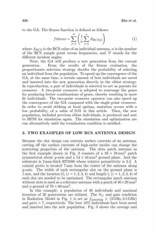
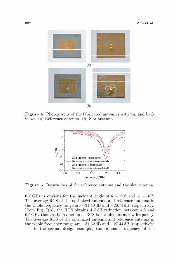
The photographs of the reference antenna and the proposedantenna are shown in Fig. 4. Fig. 5 shows the measured and simulatedreturn loss of the reference patch antenna and the optimized slotantenna. It can be observed that the impedance bandwidth of theslot antenna almost equals to that of the reference antenna. Themeasured results have a good consistency with simulation ones. Inaddition, both the xoz-plane and yoz-plane radiation patterns of theantennas are shown in Fig. 6. The slot antenna has normal radiationperformance compared with the reference antenna.
In scattering modeling, the incident plane wave is with the θpolarization. Fig. 7 depicts two typical angles’ RCS of the antennasversus frequency. In Fig. 7(a), the monostatic RCS value of theoptimized antenna is reduced almost in the whole frequency rangeof 2–8 GHz. Especially, the RCS reduction in the frequency band of
332 Zhu et al.
(a)
(b)
Figure 4. Photographs of the fabricated antennas with top and backviews. (a) Reference antenna. (b) Slot antenna.
2.6 2.8 3.0 3.2 3.4-30
-25
-20
-15
-10
-5
0
S11(d
B)
Frequency(GHz)
Slot antenna (measured)Reference antenna (measured)Slot antenna (simulated)Reference antenna (simulated)
Figure 5. Return loss of the reference antenna and the slot antenna.
6–8GHz is obvious for the incident angle of θ = 60◦ and ϕ = 45◦.The average RCS of the optimized antenna and reference antenna inthe whole frequency range are −31.49 dB and −26.71 dB, respectively.From Fig. 7(b), the RCS obtains 4–5 dB reduction between 4.5 and6.5GHz though the reduction of RCS is not obvious at low frequency.The average RCS of the optimized antenna and reference antenna inthe whole frequency range are −31.32 dB and −27.44 dB, respectively.
In the second design example, the resonant frequency of the
Progress In Electromagnetics Research, Vol. 122, 2012 333
-20
-10
0
10
0
30
60
90
120
150
180
210
240
270
300
330
-20
-10
0
10
Reference antenna
Slot ant enna
-20
-10
0
10
0
30
60
90
120
150
180
210
240
270
300
330
-20
-10
0
10
Reference antenna
Slot antenna
(a) (b)
Figure 6. Simulated radiation pattern of the reference antenna andthe slot antenna at 3.23GHz. (a) xoz-plane. (b) yoz-plane.
2 3 4 5 6 7 8
-40
-35
-30
-25
-20
-15
RC
S(d
Bsm
)
Frequency (GHz)
Reference antenna Slot antenna
2 3 4 5 6 7 8-50
-45
-40
-35
-30
-25
-20
-15
RC
S(d
Bsm
)
Frequency (GHz)
Reference antenna Slot antenna
(a) (b)
Figure 7. Simulated RCS of the reference antenna and the optimizedslot antenna. (a) Incident angle (θ = 60◦, ϕ = 45◦). (b) Incident angle(θ = 60◦, ϕ = 90◦).
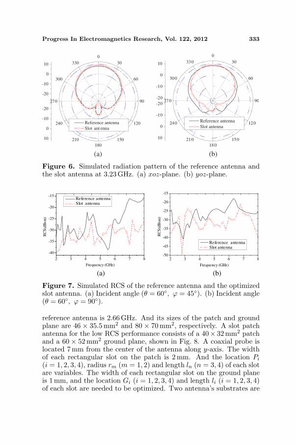
reference antenna is 2.66 GHz. And its sizes of the patch and groundplane are 46 × 35.5mm2 and 80 × 70mm2, respectively. A slot patchantenna for the low RCS performance consists of a 40× 32mm2 patchand a 60× 52mm2 ground plane, shown in Fig. 8. A coaxial probe islocated 7 mm from the center of the antenna along y-axis. The widthof each rectangular slot on the patch is 2 mm. And the location Pi
(i = 1, 2, 3, 4), radius rm (m = 1, 2) and length ln (n = 3, 4) of each slotare variables. The width of each rectangular slot on the ground planeis 1 mm, and the location Gi (i = 1, 2, 3, 4) and length li (i = 1, 2, 3, 4)of each slot are needed to be optimized. Two antenna’s substrates are
334 Zhu et al.
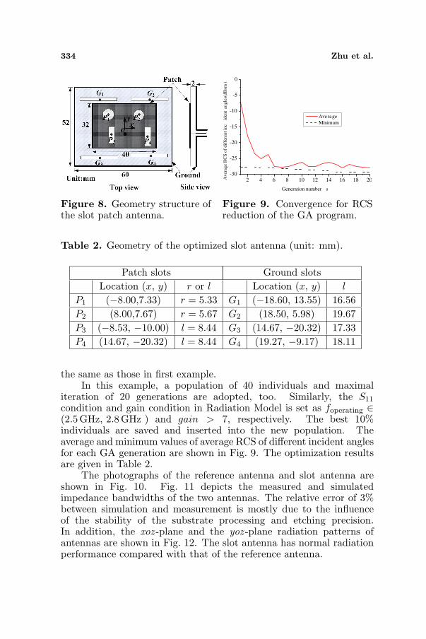
Figure 8. Geometry structure ofthe slot patch antenna.
2 4 6 8 10 12 14 16 18 20-30
-25
-20
-15
-10
-5
0
Av
erag
e R
CS
of
dif
fere
nt
inc
iden
t an
gle
s(d
Bsm
)
Generation number s
Average
Minimum
Figure 9. Convergence for RCSreduction of the GA program.
Table 2. Geometry of the optimized slot antenna (unit: mm).
Patch slots Ground slotsLocation (x, y) r or l Location (x, y) l
P1 (−8.00,7.33) r = 5.33 G1 (−18.60, 13.55) 16.56P2 (8.00,7.67) r = 5.67 G2 (18.50, 5.98) 19.67P3 (−8.53, −10.00) l = 8.44 G3 (14.67, −20.32) 17.33P4 (14.67, −20.32) l = 8.44 G4 (19.27, −9.17) 18.11
the same as those in first example.In this example, a population of 40 individuals and maximal
iteration of 20 generations are adopted, too. Similarly, the S11
condition and gain condition in Radiation Model is set as foperating ∈(2.5GHz, 2.8 GHz ) and gain > 7, respectively. The best 10%individuals are saved and inserted into the new population. Theaverage and minimum values of average RCS of different incident anglesfor each GA generation are shown in Fig. 9. The optimization resultsare given in Table 2.
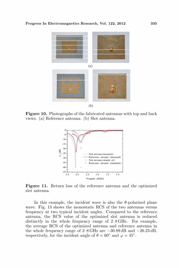
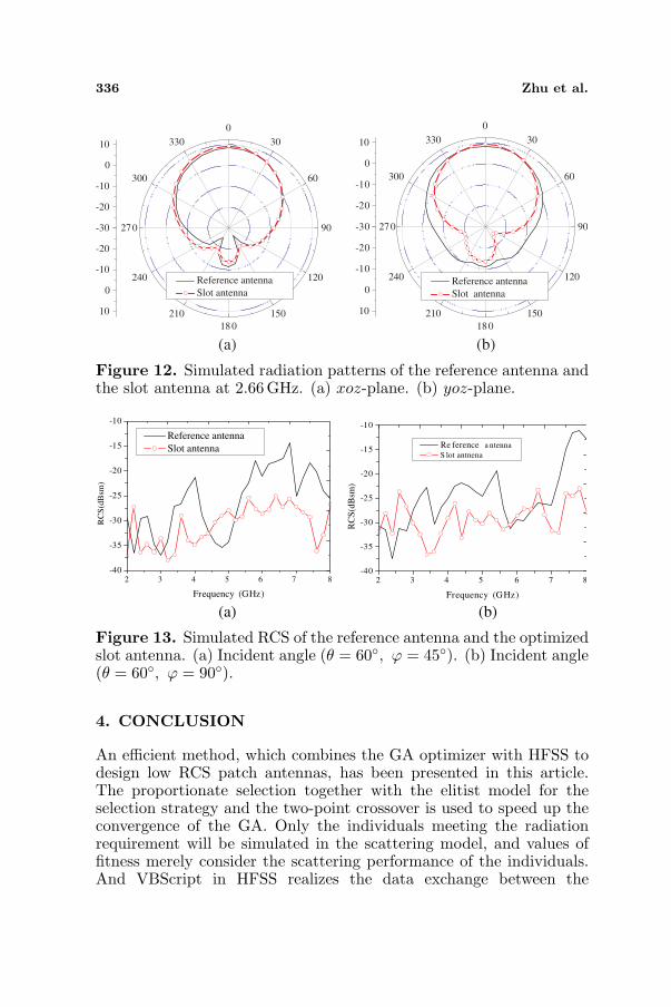
The photographs of the reference antenna and slot antenna areshown in Fig. 10. Fig. 11 depicts the measured and simulatedimpedance bandwidths of the two antennas. The relative error of 3%between simulation and measurement is mostly due to the influenceof the stability of the substrate processing and etching precision.In addition, the xoz -plane and the yoz -plane radiation patterns ofantennas are shown in Fig. 12. The slot antenna has normal radiationperformance compared with that of the reference antenna.
Progress In Electromagnetics Research, Vol. 122, 2012 335
(a)
(b)
Figure 10. Photographs of the fabricated antennas with top and backviews. (a) Reference antenna. (b) Slot antenna.
2.4 2.6 2.8 3.0 3.2 3.4-45
-40
-35
-30
-25
-20
-15
-10
-5
0
S lot an tenna (measured)
Reference ant enna (measured)
S lot an tenna (simulat ed )
Reference ant enna (simulated )
S11(d
B)
Frequenc y[GHz]
Figure 11. Return loss of the reference antenna and the optimizedslot antenna.
In this example, the incident wave is also the θ-polarized planewave. Fig. 13 shows the monostatic RCS of the two antennas versusfrequency at two typical incident angles. Compared to the referenceantenna, the RCS value of the optimized slot antenna is reduceddistinctly in the whole frequency range of 2–8 GHz. For example,the average RCS of the optimized antenna and reference antenna inthe whole frequency range of 2–8 GHz are −30.89 dB and −26.23 dB,respectively, for the incident angle of θ = 60◦ and ϕ = 45◦.
336 Zhu et al.
-30
-20
-10
0
10
0
30
60
90
120
150
180
210
240
270
300
330
-20
-10
0
10
Reference antenna
Slot antenna
-30
-20
-10
0
10
0
30
60
90
120
150
180
210
240
270
300
330
-20
-10
0
10
Reference antenna
Slot antenna
(a) (b)
Figure 12. Simulated radiation patterns of the reference antenna andthe slot antenna at 2.66GHz. (a) xoz-plane. (b) yoz-plane.
2 3 4 5 6 7 8-40
-35
-30
-25
-20
-15
-10
RC
S(d
Bsm
)
Frequency (GHz)
Reference antenna
Slot antenna
2 3 4 5 6 7 8-40
-35
-30
-25
-20
-15
-10
RC
S(d
Bsm
)
Frequency (GHz)
Re ference a ntenna
S lot antnena
(a) (b)
Figure 13. Simulated RCS of the reference antenna and the optimizedslot antenna. (a) Incident angle (θ = 60◦, ϕ = 45◦). (b) Incident angle(θ = 60◦, ϕ = 90◦).
4. CONCLUSION
An efficient method, which combines the GA optimizer with HFSS todesign low RCS patch antennas, has been presented in this article.The proportionate selection together with the elitist model for theselection strategy and the two-point crossover is used to speed up theconvergence of the GA. Only the individuals meeting the radiationrequirement will be simulated in the scattering model, and values offitness merely consider the scattering performance of the individuals.And VBScript in HFSS realizes the data exchange between the
Progress In Electromagnetics Research, Vol. 122, 2012 337
optimization module and simulation module automatically. Twoexamples of patch antennas are designed with the proposed method.The simulated and measured results show that the optimized slotantennas realize the RCS reduction in a broad frequency range of 2–8GHz at different incident angles, while maintaining good radiationperformances.
ACKNOWLEDGMENT
This work was supported in part by the DPR Foundation of China(11DZ0208 and 10DZ0204), the National Natural Science Foundationof China (60901023), and the Fundamental Research Funds for theCentral Universities (ZYGX2010J043 and ZYGX2009J041).
REFERENCES
1. Jiang, W., T. Hong, Y. Liu, S.-X. Gong, Y. Guan, and S. Cui,“A novel technique for radar cross section reduction of printedantennas,” Journal of Electromagnetic Waves and Applications,Vol. 24, No. 1, 51–60, 2010.
2. Hong, T., L.-T. Jiang, Y.-X. Xu, S.-X. Gong, and W. Jiang, “Ra-diation and scattering analysis of a novel circularly polarized slotantenna,” Journal of Electromagnetic Waves and Applications,Vol. 24, No. 13, 1709–1720, 2010.
3. Xu, H.-Y., H. Zhang, K. Lu, and X.-F. Zeng, “A holly-leaf-shapedmonopole antenna with low RCS for UWB application,” ProgressIn Electromagnetics Research, Vol. 117, 35–50, 2011.
4. Xu, H.-Y., H. Zhang, X. Yin, and K. Lu, “Ultra-wideband Kochfractal antenna with low backscttering cross section,” Journalof Electromagnetic Waves and Applications, Vol. 24, No. 17–18,2615–2623, 2010.
5. Gonzalez, C. G., Y. Alvarez Lopez, A. D. Casas, andF. Las-Heras Andres, “Characterization of antenna interactionwith scatterers by means of equivalent currents,” Progress InElectromagnetics Research, Vol. 116, 185–202, 2011.
6. Knot, E. F., J. F. Sbaeffer, and M. T. Tuley, Radar Cross Section,2nd edition, Artech House, London, 1993.
7. Zhao, S.-C., B.-Z. Wang, and Q.-Q. He, “Broadband crosssection reduction of a rectangular patch antenna,” Progress InElectromagnetics Research, Vol. 79, 263–275, 2008.
8. Kumar, R. and P. Malathi, “Design of CPW-fed ultra widebandfractal antenna and backscattering reduction,” Journal of
338 Zhu et al.
Microwaves, Optoelectronics and Electromagnetic Applications,Vol. 9, No. 1, 10–19, 2010.
9. Misran, N., R. Cahill, and V. F. Fusco, “RCS reduction techniquefor reflectarray antennas,” Electronics Letters, Vol. 39, No. 23,1630–1632, 2003.
10. Ren, L.-S., Y.-C. Jiao, J.-J. Zhao, and F. Li, “RCS reductionfor a FSS-backed reflectarray using a ring element,” Progress InElectromagnetics Research Letters, Vol. 26, 115–123, 2011.
11. Zheng, Q.-R., Y.-M. Yan, X.-Y. Cao, and N.-C. Yuan, “Highimpedance ground plane (HIGP) incorporated with resistancefor radar cross section (RCS) reduction of antenna,” Progress InElectromagnetics Research, Vol. 84, 307–319, 2008.
12. Oraizi, H. and A. Abdolali, “Combination of MLS, GA& CG for the reduction of RCS of multilayered cylindricalstructures composed of dispersive metamaterials,” Progress InElectromagnetics Research B, Vol. 3, 227–253, 2008.
13. Wang, W., S. Gong, X. Wang, Y. Guan, and W. Jiang,“Differential evolution algorithm and method of moments forthe design of low-RCS antenna,” IEEE Antennas and WirelessPropagation Letters, Vol. 9, 295–298, 2010.
14. Rahmat-Samii, Y. and E. Michielssen, Electromagnetic optimiza-tion by Genetic Algorithms, John Wiley & Sons, New York, 1999.
15. Xu, O., “Collimation lens design using AI-GA technique forGaussian radiators with arbitrary aperture field distribution,”Journal of Electromagnetic Waves and Applications, Vol. 25,No. 5–6, 743–754, 2011.
16. Jian, L., G. Xu, J. Song, H. Xue, D. Zhao, and J. Liang,“Optimum design for improving modulating-effect of coaxialmagnetic gear using response surface methodology and geneticalgorithm,” Progress In Electromagnetics Research, Vol. 116, 297–312, 2011.
17. Reza, A. W., M. S. Sarker, and K. Dimyati, “A novelintegrated mathematical approach of ray-tracing and geneticalgorithm for optimizing indoor wireless coverage,” Progress InElectromagnetics Research, Vol. 110, 147–162, 2010.
18. Kerkhoff, A. J., R. L. Rogers, and H. Ling, “Design and analysisof planar monopole antennas using a genetic algorithm approach,”IEEE Transactions on Antennas and Propagation, Vol. 52, No. 10,2709–2718, 2004.
19. Kerkhoff, A. J. and H. Ling, “Design of a band-notched planarmonopole antenna using genetic algorithm optimization,” IEEE
Progress In Electromagnetics Research, Vol. 122, 2012 339
Transactions on Antennas and Propagation, Vol. 55, No. 3, 604–610, 2007.
20. Jones, E. A. and W. T. Joines, “Design of Yagi-Uda antennasusing genetic algorithms,” IEEE Transactions on Antennas andPropagation, Vol. 45, No. 9, 1386–1392, 1997.
21. Kuwahara, Y., “Multiobjective optimization design of Yagi-Udaantenna,” IEEE Transactions on Antennas and Propagation,Vol. 53, No. 6, 1984–1992, 2005.
22. Villegas, F. J., T. Cwik, Y. Rahmat-Samii, and M. Manteghi,“A parallel electromagnetic genetic algorithm optimization (EGO)application for patch antenna design,” IEEE Transactions onAntennas and Propagation, Vol. 52, No. 9, 2424–2435, 2004.
23. Pu, T., K.-M. Huang, B. Wang, and Y. Yang, “Application ofmicro-genetic algorithm to the design of matched high gain patchantenna with zero-refractive-index matematerial lens,” Journal ofElectromagnetic Waves and Applications, Vol. 24, No. 8–9, 1207–1217, 2010.
24. Zhang, Y.-J., S.-X. Gong, X. Wang, and W.-T. Wang, “A hybridgenetic-algorithm space-mapping method for the optimizationof broadband aperture-coupled asymmetrical U-shaped slotantennas,” Journal of Electromagnetic Waves and Applications,Vol. 24, No. 16, 2139–2153, 2010.
25. Dadgarnia, A. and A. A. Heidari, “A fast systematic approachfor microstrip antenna design and optimization using ANFIS andGA,” Journal of Electromagnetic Waves and Applications, Vol. 24,No. 16, 2207–2221, 2010.
26. Allard, R. J., D. H. Werner, and P. L. Werner, “Radiation patternsynthesis for arrays of conformal antennas mounted on arbitrarily-shaped three-dimensional platforms using genetic algorithms,”IEEE Transactions on Antennas and Propagation, Vol. 51, No. 5,1054–1062, 2003.
27. Villegas, F. J., “Parallel genetic-algorithm optimization of shapedbeam coverage areas using planar 2-D phased arrays,” IEEETransactions on Antennas and Propagation, Vol. 55, No. 6, 1745–1753, 2007.
28. Jain, R. and G. S. Mani, “Dynamic thinning of antenna arrayusing genetic algorithm,” Progress In Electromagnetics ResearchB, Vol. 32, 1–20, 2011.
29. Siakavara, K., “Novel fractal antenna arrays for satellite networks:Circular ring Sierpinski carpet arrays optimized by geneticalgorithms,” Progress In Electromagnetics Research, Vol. 103,115–138, 2010.
![Performance Optimization of a Microstrip Patch Antenna ... · COAXIAL PROBE FED RECTANGULAR MICROSTRIP PATCH ANTENNA [1] R. Garg, P. Bhartia, I. Bahl, and A. Ittipibon, Microstrip](https://img.pdfslide.us/doc/110x75/6038ae9acc6dac1a041c5fcd/performance-optimization-of-a-microstrip-patch-antenna-coaxial-probe-fed-rectangular.jpg)


![RCS Reduction of Patch Array Using Shorted Stubs Metamaterial … · 2018-12-11 · EBG) structure to reduce the . RCS. of patch antenna array using a conducting polymer [5]. Shiv](https://img.pdfslide.us/doc/110x75/5f4fc5db689e5564030f0e6b/rcs-reduction-of-patch-array-using-shorted-stubs-metamaterial-2018-12-11-ebg.jpg)


![[Rcs Iot] Rcs-e v1-2- Joyn](https://img.pdfslide.us/doc/110x75/577cd0231a28ab9e78917fbc/rcs-iot-rcs-e-v1-2-joyn.jpg)