Embed Size (px)
Citation preview
REC-ERC-74-19
Engineering and Research Center
Bureau of Reclamation
September 1974
Prepared for theICE RESEARCH MANAGEMENT COMMITTEE
DESIGN AND OPERATION OFSHALLOW RIVER DIVERSIONSIN COLD REGIONS
MS-230 (8-70) Bureau of Recla.mation
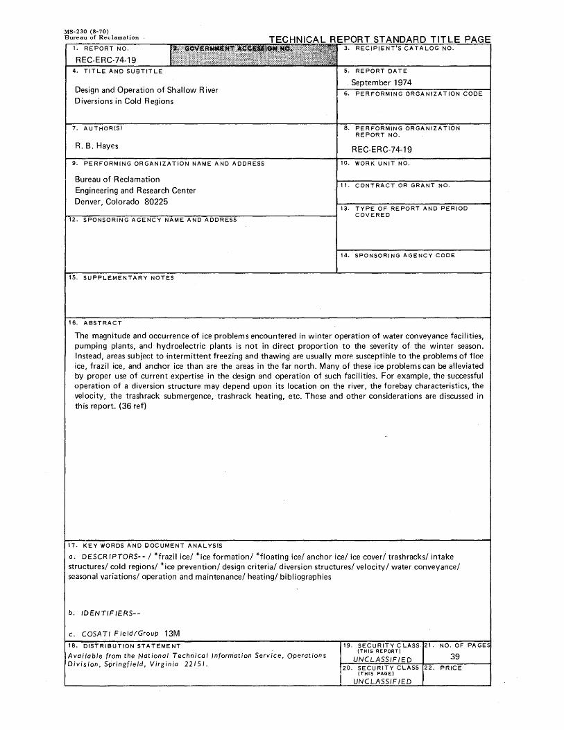
1. REPORT NO.
REC-ERC-74-19 4. TITLE AND SUBTITLE
Design and Operation of Shallow River
Diversions in Cold Regions
7. AUTHOR(Sl
R. B. Hayes
9. PERFORMING ORGANIZATION NAME AND ADDRESS
Bureau of Reclamation
Engineering and Research Center
Denver, Colorado 80225
. SPONSORING AGENCY NAME AND ADORE
15. SUPPLEMENTARY NOTES
16. ABSTRACT
PAGE
5. REPORT DATE
. September 1974 6. PERFORMING ORGANIZATION CODE
8. PERFORMING ORGANIZATION REPORT NO.
REC-ERC-74-19
10. WORK UNIT NO.
11. CONTRACT OR GRANT NO.
13. TYPE OF REPORT AND PERIOD COVERED
14. SPONSOR! NG AGENCY CODE
The magnitude and occurrence of ice problems encountered in winter operation of water conveyance facilities, pumping plants, and hydroelectric plants is not in direct proportion to the severity of the winter season. Instead, areas subject to intermittent freezing and thawing are usually more susceptible to the problems of floe ice, frazil ice, and anchor ice than are the areas in the far north. Many of these ice problems can be alleviated by proper use of current expertise in the design and operation of such facilities. For example, the successful operation of a diversion structure may depend upon its location on the river, the forebay characteristics, the velocity, the trashrack submergence, trashrack heating, etc. These and other considerations are discussed in this report. (36 ref)
17. KEY WORDS AND DOCUMENT ANALYSIS
a. DESCRIPTORS-- I *frazil ice/ *ice formation/ *floating ice/ anchor ice/ ice cover/ trash racks/ intake structures/ cold regions/ *ice prevention/ design criteria/ diversion structures/ velocity I water conveyance/ seasonal variations/ operation and maintenance/ heating/ bibliographies
b. /DENTIF IERS--
c. COSATI Field/Group 13M
18. DISTRIBUTION STATEMENT
Available from the National Technical Information Service, Operations Division, Springfield, Virginia 22151.
19. SECURITY CLASS (THIS REPORT)
UNCLASS/F/E 20. SECURITY LAS
(THIS PAGE)
UNCLASS/F ED
NO. OF PAGE
39 PRICE
REC-ERC-74-19
DESIGN AND OPERATION OF
SHALLOW RIVER DIVERSIONS
IN COLD REGIONS
Prepared by
R. B. Hayes, Division of Design
for the
Ice Research Management Committee
September 1974
Division of General Research Engineering and Research Center Denver, Colorado
UNITED STATES DEPARTMENT OF THE INTERIOR * BUREAU OF RECLAMATION
ACKNOWLEDGMENT
This report was prepared for the Ice Research Management Committee of the Bureau of Reclamation, under the direction of P. H. Burgi, Chairman. Special thanks are offered to Robert Ferrese and A. J. Aisenbrey, Jr., of the Hydraulic Structures Branch for their cooperation, and to E. L. Pemberton, Division of Planning Coordination, for his paragraphs on sedimentation, section C2.
The Ice Research Management Committee consists of:
P. H. Burgi, Chairman R. B. Hayes Dr. W. E. Howell
E. L. Pemberton B. J. Peter L. R. Swarner
Division of Research Division of Design Division of Atmospheric Water
Resources Management Division of Planning Coordination Division of Design Division of Water O&M
The information contained in this report regarding commercial products may not be used for advertising or promotional purposes and is not to be construed as endorsement of any product by the Bureau of Reel am at ion.
PREFACE
Ice formation on reservoirs, rivers, canals, and associated structures hinders and, at times, prevents winter operation on a number of USBR (Bureau of Reclamation) projects. In an effort to increase the reliability and efficiency of our present projects and improve design criteria related to future projects in cold regions, the USBR established the Ice Research Management Committee. The objective of the Committee is to develop and manage an ice research program directed toward solving ice problems on USB R projects.
This report is the second in a series of reports sponsored by the Ice Research Management Committee. The first report, REC-ERC-74-15, is titled "Prevention of Frazil Ice Clogging of Water Intakes by Application of Heat." These and subsequent reports are being prepared to familiarize USBR personnel with the art and/or science of winter operation of water resource projects in cold regions. It is hoped that these reports will be a valuable aid to design and operation personnel and will stimulate continued creative approaches to ice problems during winter operation. The Committee encourages USBR personnel to relate their problems and success in ice engineering so that this and future reports may be current with the latest technology in the field of ice engineering.

A. Research Program
1. General
(a) USBR diversion requirements (b) Literature review (c) Experience record
2. Model Studies
B. Characteristics of Ice
1. Fraz!l Ice . .
(a) Characteristics (b) Formation of frazil ice (c) Problems caused by frazil ice
2. Anchor Ice . . . . 3. Surface Ice (Sheet Ice)
(a) Formation (b) Ice Pressure
C. Design Guidelines
1. General 2. Location of Diversion
CONTEI'JTS
(a) Channel hydraulics, sediment transport characteristics, and hydrologic factors . . . . . . .
(b) Sediment problems at a diversion . (c) Location to avert sediment problems (d) Location to avert ice problems
3. Diversion Pool
(a) General (b) Ice-covered diversion pool (c) Ice-free diversion pool
4. Spillway 5. Ice Sluiceway 6. Forebay Area 7. Intake Structure
(a) General (b) Curtain wall (c) Trashracks (d) Diversion gates (e) Superstructure
Page
1 2
2
2
2
2 2 3
3 3
3 4
4
4 4
5 5 6 6
7
7 7 7
7 7 8 8
8 8 9
11 11
CONTENTS-Continued
8. Drop-inlet Structures 11
(a) General 11 (b) Diversion pool 11 (c) Weir structure 11 (d) Intake structure 11 (e) Trash racks 12
9. Diversion to Open Canals 12
(a) General 12 (b) Avoidance of frazil ice and anchor ice production 12 (c) Ice-covered canal 12 (d) Ice-free canal 13 (e) Canal forebay 13 (f) Intake structure 13
10. Bubbler Systems 13
D. Operation of Shallow River Diversions 13
1. River Control 13 2. Diversion Pool 14 3. Spillway 14 4. Ice Sluiceway 14 5. Fore bay 14 6. Intake Structure 14
(a) Trashrack submergence 14 (b) Trashrack cover 14 (c) Trashrack heating 15 (d) Removal or replacement of trashracks 15
7. Operation of Canals 15
(a) General 15 (b) Operation of ice-free canal 15 (c) Operation of ice-covered canal 16
8. Monitoring and Control Equipment 16
E. Recommendations for Further Research 16
1. Shallow River Diversions in General 16 2. Model Study of a Specific Diversion Facility 16 3. Monitor and Control Equipment 16
F. Glossary of Terms 16 G. Bibliography 17
ii
CONTENTS-Continued
Appendix 1-Heat Loss Factors
1. General 2. Reservoirs 3. Canals 4. Tunnels . 5. Buried Conduit 6. Exposed Pipeline
Appendix 11-Experience With Shallow River Diversions in Cold Regions
A. Bureau of Reclamation (USB R} Experience B. Public and Private Diversion Experience
Figure
1 2 3
4 5
6
A-1
A-2 A-3 A-4
A-5
A-6
A-7
A-8 A-9
Table
A-1
LIST OF FIGURES
Typical diversion to power canal . . . . . . . . . . Forces exerted by an expanding ice sheet . . . . . . . Optimum location on river bend to exclude sediment or float-
ing ice .................. . Ice control features . . . . . . . . . . . . . . . Schematic view from the Burfell diversion which utilizes sepa
rate ice and sediment sluices Typical river diversion intake structures . . . . . . . .
LIST OF FIGURES IN APPENDICES
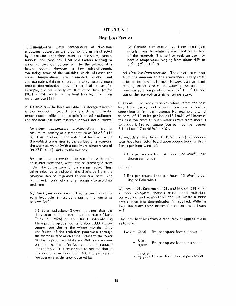
Ice formation-Factors that affect the rate of cooling of a sec-tion of river water . . . . .
Pipe cover to avoid freezing . . . . . . . . . . . . Typical record of weather and ice . . . . . . . . . . Ivanhoe Diversion Dam-North side collection system-General
plan and sections . . . . . . . . . . . . . . . Layout Creek stream inlet-Strawberry Aqueduct-General plan and
sections . . . . . . . . . . . . . . . . . . . Trashrack metalwork-Water Hollow Diversion Dam headworks-
Strawberry Aqueduct . . . . . . . . . . . . Slide gate heating installation for Layout Creek and Water
Hollow-Strawberry Aqueduct . . . . . . . . . Radial gate hoist installation-Knight Diversion Dam sluiceway Sluiceway, radial gate, and heating system . . . . . . .
TABLE IN APPENDICES
Experience with shallow river diversions in cold regions
iii
19
19 19 19 20 21 21
23
23 26
1 4
5 8
9 9
20 21 32
34
35
36
37 38 39
27

A. RESEARCH PROGRAM
1. GeneraL-In an effort to increase the reliability and efficiency of USBR (Bureau of Reclamation) power and water projects, the Bureau, through the Ice Research Management Committee, is exploring several areas that present problems in winter operation in cold regions [ 1] . *One such area is that of water diversion from shallow rivers during the winter. For the purpose of this discussion, a shallow river is defined as one having a depth of 10 feet or less. A discussion of diversion from very small streams having little or no flow in the winter months is included in the section on Drop-inlet Structures, CS.
While diversions from deeper rivers may be susceptible to some ice problems, ice problems are usually more intense and often unavoidable in shallow river diversions. The USBR ice committee believes that many ice problems can be eliminated or minimized by following design guidelines and operating procedures based upon successful experience and an understanding of hydraulics.
It should not be assumed that ice problems vary directly with the severity of the cold weather. In fact, the coldest regions are fortunate in that their streams, lakes, and canals form a protective ice cover early in the winter, permitting operation under the cover without some of the ice problems experienced in milder climates. In contrast, the regions which are intermittently cold may have ice problems frequently, as temperature changes result in cycles of alternate freezing and thawing.
As the USBR diversion requirements are similar to those for many public and private power and water companies, a review of diversion experience was conducted through a literature review and through correspondence with companies involved in water diversion.
(a) USBR diversion requirements.-The USBR diversion facilities are designed to divert 'irrigation water, municipal or industrial water, or water for hydroelectric powerplants. The diversion requirements fall into two categories:
( 1) Diversion to a closed conduit, pumping plant, or powerplant.
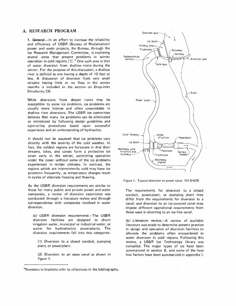
(2) Diversion to an open canal as shown in figure'1.
Wasteway gate structure and sluiceway
Diversion pool
Figure 1. Typical diversion to power canal. 1 01-D-625
The requirements for diversion to a closed conduit, powerplant, or pumping plant may differ from the requirements for diversion to a canal; and diversion to an ice-covered canal may impose different operational requirements from those used in diverting to an ice-free canal.
(b) Literature review.-A review of available literature was made to determine present practice in design and operation of diversion facilities to alleviate the problems often encountered in water diversion in cold regions. Following this review, a USBR Ice Technology library was compiled. The major types of ice have been summarized in section B, and some of the heat loss factors have been summarized in appendix I.
*Numbers in brackets refer to references in the bibliography.
(c) Experience record.-Many USBR offices, private power and irrigation companies, and municipalities were contacted concerning their experience with shallow river diversion practices in cold regions. The pertinent features of their facilities, together with operational problems and solutions, are summarized in appendix II.
2. Model Studies.-Pians are underway to perform laboratory model studies for a shallow river diversion on the Bureau's Fryingpan-Arkansas project located in Colorado. The experience of others in operation of such water diversion facilities, and the design guidelines presented in section C will be considered in planning the model studies.
B. CHARACTERISTICS OF ICE
The major types of ice that present problems in diversion facilities include frazil ice, anchor ice, and surface ice. These are described briefly as follows (for further discussion see bibliography reference [2]):
1. Frazil Ice_-
(a) Characteristics.-Frazil ice is the crystalline form of ice occurring in turbulent water that has become supercooled by a small fraction of a degree [3] . Supercooling is defined as the attainment of temperatures lower than the normal freezing point, without actually freezing. The character of frazil ice particles varies as follows:
( 1) Active state.-When frazil ice is first produced, the particles are very adhesive and accumulate in large masses. These masses adhere to other objects, particularly to metals such as trashracks. Flow through the trashracks or through a water prism may become completely blocked [ 4] .
(2) Inactive state.-The usual duration of the active state is only a few minutes, after which time the frazil ice becomes inactive. Inactive frazil ice is not sticky and can often be passed through trashracks or turbines in large quantities without adverse effects.
(b) Formation of frazil ice.-Frazil ice forms throughout the body of the water prism. Its production is not ordinarily initiated during
- daylight hours as the rate of cooling is inadequate, but once started, it sometimes continues during the day. Other conditions governing the production of frazil ice are as follows:
2
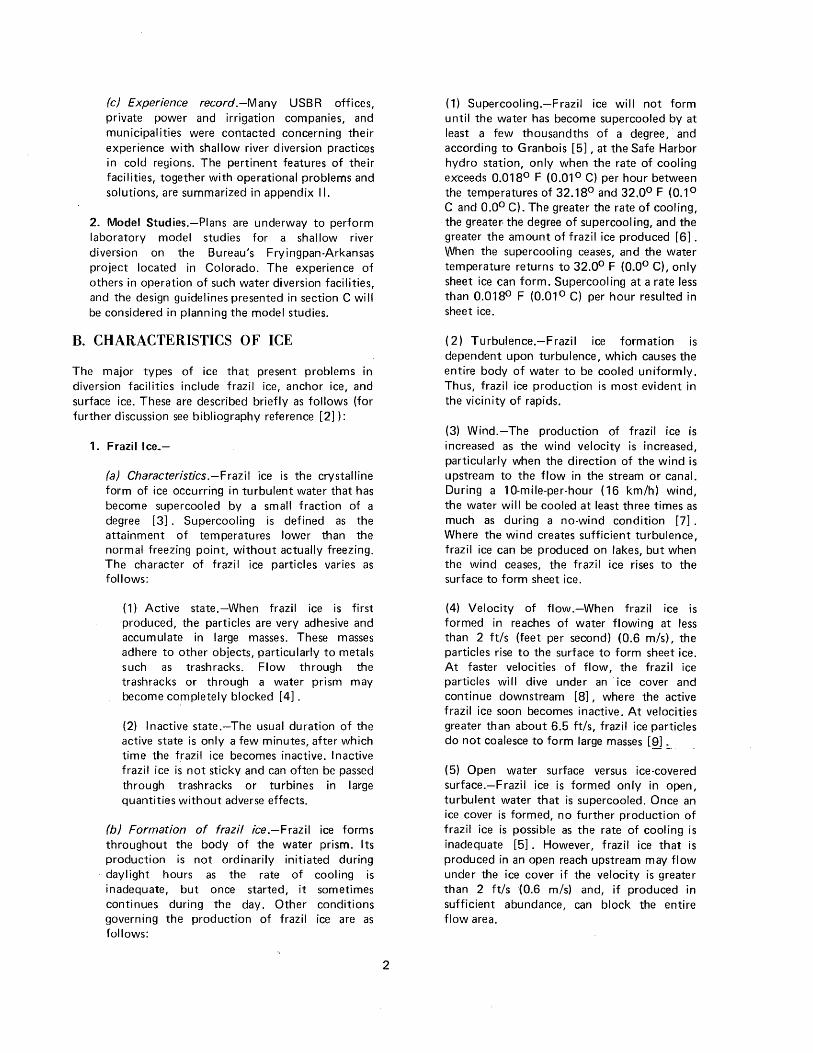
(1) Supercooling.-Frazil ice will not form until the water has become supercooled by at least a few thousandths of a degree, and according to Granbois [5], at the Safe Harbor hydro station, only when the rate of cooling exceeds 0.018° F (0.01 ° C) per hour between the temperatures of 32.18° and 32.0° F (0.1 ° C and 0.0° C). The greater the rate of cooling, the greater the degree of supercooling, and the greater the amount of frazil ice produced [6] . When the supercooling ceases, and the water temperature returns to 32.0° F (0.0° C), only sheet ice can form. Supercooling at a rate less than 0.018° F (0.01 ° C) per hour resulted in sheet ice.
( 2) Turbulence.-Frazil ice formation is dependent upon turbulence, which causes the entire body of water to be cooled uniformly. Thus, frazil ice production is most evident in the vicinity of rapids.
(3) Wind.-The production of frazil ice is increased as the wind velocity is increased, particularly when the direction of the wind is upstream to the flow in the stream or canal. During a 1 0-mile-per-hour ( 16 km/h) wind, the water will be cooled at least three times as much as during a no-wind condition [7] . Where the wind creates sufficient turbulence, frazil ice can be produced on lakes, but when the wind ceases, the frazil ice rises to the surface to form sheet ice.
(4) Velocity of flow.-When frazil ice is formed in reaches of water flowing at less than 2 ft/s (feet per second) (0.6 m/s), the particles rise to the surface to form sheet ice. At faster velocities of flow, the frazil ice particles will dive under an ice cover and continue downstream [8], where the active frazil ice soon becomes inactive. At velocities greater than about 6.5 ft/s, frazil ice particles do not coalesce to form large masses [ru =---
(5) Open water surface versus ice-covered surface.-Frazil ice is formed only in open, turbulent water that is supercooled. Once an ice cover is formed, no further production of frazil ice is possible as the rate of cooling is inadequate [5]. However, frazil ice that is produced in an open reach upstream may flow under the ice cover if the velocity is greater than 2 ft/s (0.6 m/s) and, if produced in sufficient abundance, can block the entire flow area.
(6) Other covers.-A structural cover, as well as an ice cover, prevents formation of frazil ice in the covered reach. A heavy cover of fog is equally effective in reducing heat loss from the water surface.
( 7) M i see llaneous.-An increase in the production of frazil ice results from the presence of a nucleus such as suspended sand or silt particles in the water [9], and from the entrance of blowing snow into the water [10].
(c) Problems caused by frazil ice.-Problems caused by frazil ice are not limited to active frazil and are not precluded by forming an ice cover. Any hydraulic structure can function satisfactorily until the concentration of ice in the flow exceeds a certain limit. The limit is much lower with active frazil ice than with inactive [ 11].
The more corn mon problems are summarized as follows:
( 1) F razil ice is very sticky when first produced (active state). The frazil needles coalesce to form small masses which in turn coalesce to form larger masses of spongy frazil. Active frazil ice adheres to objects having a good thermal conductivity, such as steel trash racks and turbines when they are at a temperature of 32° F (0° C) or below. The accumulation of frazil ice on the racks can quickly block the flow through the racks, and where racks are not provided, it can block the flow through turbines.
(2) F razil ice (active or inactive) can also accumulate in zones of low velocity flow in sufficient proportions to block the flow in the entire water prism. The accumulation often starts when active frazil ice adheres to piers or other obstructions. Inactive frazil can usually pass through trashracks, pumps, or turbines without damage.
(3) While the production of frazil ice at a particular site usually continues for only a few minutes, its production in rapids may continue for days [ 12], manufacturing enough frazil ice to completely fill a channel or a small downstream reservoir. Scherman [ 13] discusses the volume of frazil ice that can be produced under various conditions. For problems with ice jams, see bibliography reference [ 14] .
3
2. Anchor lce.-1 n contrast to frazil ice, which forms throughout the body of the water prism, anchor ice forms on the bottom of shallow streams or canals, and is formed on clear, cold nights when radiation is excessive [3] . When the sun rises, the anchor ice is usually loosened from the bottom and floats downstream.
Anchor ice can form to such an extent that its buoyancy will float the rocks on which it is formed. As a result, rocks are sometimes carried into turbines, causing considerable damage. The accumulation of anchor ice may also block the flow through trashracks.
3. Surface Ice (Sheet Ice).-
(a) Formation.-An ice cover will form readily on water flowing !'lowly. However, with a velocity of 2.2 ft/s (0.67 m/s) and greater, an ice cover will form only if the ambient air temperature remains below 0° F (say minus 18° C) for several days [ 15] . The water temperature in a stream or canal is generally uniform throughout the water prism as mixing occurs, and an ice cover forms only when all the water in the prism is close to 32° F (OO C) [ 16] .
There are many equations for determining the thickness of an ice cover based upon the air temperature and duration. Two of these equations are [ 17]:
(1) Standing water.-The Goncharov formula for ice thickness on standing water states that:
h=3.68~
where h is the resulting ice thickness in centimeters and Lt is the sum of the mean daily negative air temperatures in degrees C "from the beginning of winter."
( 2) Flowing water.-The Bydin formula which is valid for velocities of flow equal to or less than 1.6 ft/s (0.5 m/s) and a snow cover (on the ice) equal to or less than 15.7 inches (40 em), states that:
h=2~
where h is the resulting ice thickness in em, and I:t is the sum of the mean daily negative air temperatures in degrees C from the beginning of the formation of the ice cover.
Floe ice or cakes of floating ice will lodge against an obstruction or an ice cover to extend the cover upstream if the velocity in feet per second is equal to or less than [ 18] :
v = o. 1 ogJ2Qi=f
where H is the mean depth of water in feet. For faster velocities, the ice cakes dive under the edge of the established ice cover.
The thickness, t, of an established ice cover, to permit progression upstream, is a function of the velocity and depth of the stream as follows[18]:
v ----v'29H
where V is the velocity in front of the cover in feet per second, H is the mean depth in feet, and p and p' are the specific gravities of water and ice, respectively (p = 1.00, p' = about 0.90).
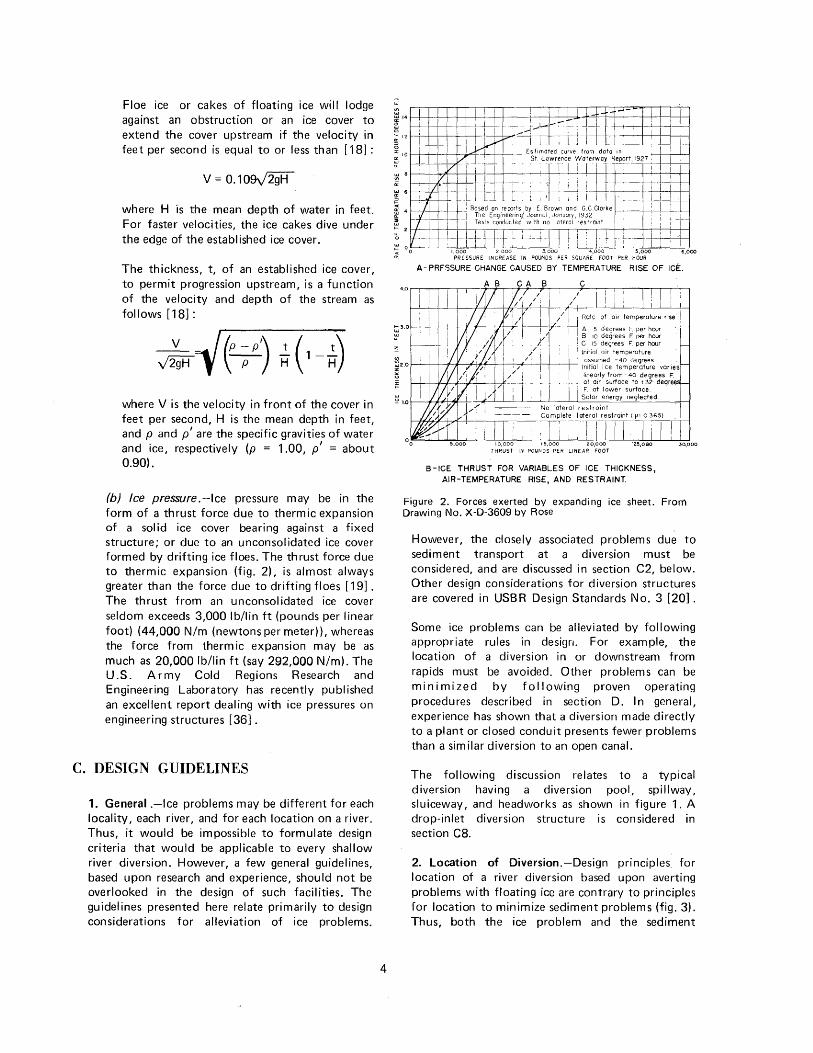
(b) Ice pressure .-Ice pressure may be in the form of a thrust force due to thermic expansion of a solid ice cover bearing against a fixed structure; or due to an unconsolidated ice cover formed by drifting ice floes. The thrust force due to thermic expansion (fig. 2), is almost always greater than the force due to drifting floes [ 19] . The thrust from an unconsolidated ice cover seldom exceeds 3,000 lb/lin ft (pounds per linear foot) (44,000 N/m (newtons per meter)), whereas the force from thermic expansion may be as much as 20,000 lb/lin ft (say 292,000 N/m). The U.S. Army Cold Regions Research and Engineering Laboratory has recently published an excellent report dealing with ice pressures on engineering structures [36].
C. DESIGN GUIDELINES
1. General .-Ice problems may be different for each locality, each river, and for each location on a river. Thus, it would be impossible to formulate design criteria that would be applicable to every shallow river diversion. However, a few general guidelines, based upon research and experience, should not be overlooked in the design of such facilities. The guidelines presented here relate primarily to design considerations for alleviation of ice problems.
4
1 I I I i i I I 1...!--+-t- I I I
1----L----l-J---l--1 --l_ut -!--L...·.....-- ~ __ L 1 J _L_ L Ll l l - I I ' I I I
,0 ..J..-"1 Estimated curve fro01 data in ++-1 '-V: I ! St Lawrence Waterway Report, 1927 ,
~---l---1-!-/* ~~- -; r- ·- - . T 1 r 1 r 1 T =~~~ '-~-'-!-lf---+-i -+-I
~8 v lllf- 'J '11 I •I' ~ 6 f----;--7.--nl -- . ·,l i I i I I
~ _ _L I LJ L . ~ I 11 ' i i I I I I i I
: 4 7 ~ Based on reports by E. Brown and G.C.Ciorke : I ! !:: 7 1 The Eng1neenng( Journal, Jonuo1y, 1932 _ : j 13 7 1 1 Tesls conducted w1lh no oteral restra1nt 7 ---
~ 2 7
1 l I t-+- L ; Ll ~~ j l j : j ~ : : I l ! _I
; 0
0 1,000 2,000 3,000 4,000 5,000 6,000 - PRESSURE INCREASE IN POUNDS PER SQUARE FOOT PER HOUR
A~ PRf'3SURE CHANGE CAUSED BY TEMPERATURE RISE OF ICE.
I
~~~-+--~~+h~~r+-+~ ' / i I Rote of air temperature rise I
~~~-+~~-Y~~--~~~ i ~ I~ ~:~;::~ ~ ~; ~~~ ; C 15 degrees F. per hour
~ i Lnitiol air temperature
~20 h--, +-1----4--l--A-#--+-+-+-'--++----+- ~~~~f~lmiecde t:~~:r~f~r~ varies _ linearly from -40 degrees F.
~ - ~~ ~; ~~~~~c~u~a~~2 degre
'o' !.O 1--------¥--JM&+ -H-__j__L__l___L_,___l_ __ ...L.J__:S:.:_:ol.::.:.or__:e::..:.:ne:."rg,_y _:_:n::._:;ego:.-:-1 e.::.:_cl:::_-:e d::._. -+--1
B -ICE THRUST FOR VARIABLES OF ICE THICKNESS, AIR-TEMPERATURE RISE, AND RESTRAINT.
Figure 2. Forces exerted by expanding ice sheet. From Drawing No. X-D-3609 by Rose
However, the closely associated problems due to sediment transport at a diversion must be considered, and are discussed in section C2, below. Other design considerations for diversion structures are covered in USB R Design Standards No. 3 [20] .
Some ice problems can be alleviated by following appropriate rules in design. For example, the location of a diversion in or downstream from rapids must be avoided. Other problems can be minimized by following proven operating procedures described in section D. In general, experience has shown that a diversion made directly to a plant or closed conduit presents fewer problems than a similar diversion to an open canal.
The following discussion relates to a typical diversion having a diversion pool, spillway, sluiceway, and headworks as shown in figure 1. A drop-inlet diversion structure is considered in section CB.
2. Location of Diversion.-Design principles. for location of a river diversion based upon averting problems with floating ice are contrary to principles for location to minimize sediment problems (fig. 3). Thus, both the ice problem and the sediment
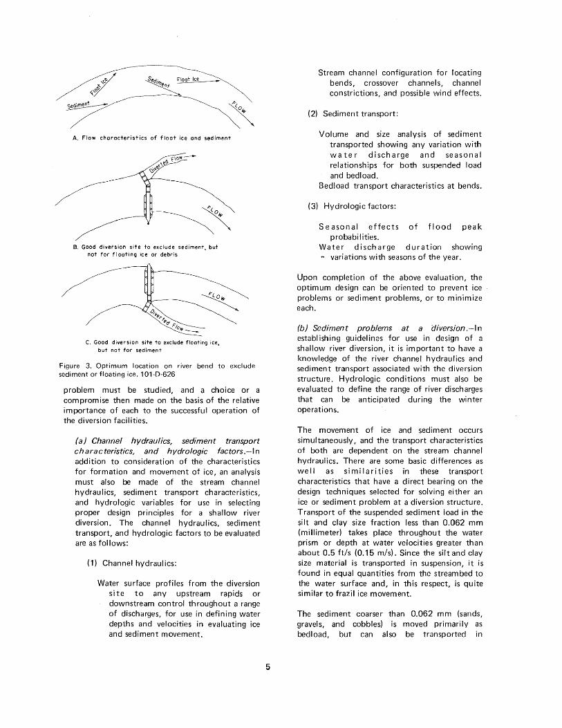
A. Flow characteristics of float ice and sediment
B. Good diversion site to exclude sediment, but not for floating ice or debris
C. Good diversion site to exclude floating ice, but not for sediment
Figure 3. Optimum location on river bend to exclude sediment or floating ice. 1 01-D-626
problem must be studied, and a choice or a compromise then made on the basis of the relative importance of each to the successful operation of the diversion facilities.
(a) Channel hydraulics, sediment transport characteristics, and hydrologic factors.-ln addition to consideration of the characteristics for formation and movement of ice, an analysis must also be made of the stream channel hydraulics, sediment transport characteristics, and hydrologic variables for use in selecting proper design principles for a shallow river diversion. The channel hydraulics, sediment transport, and hydrologic factors to be evaluated are as follows:
( 1) Channel hydraulics:
Water surface profiles from the diversion site to any upstream rapids or downstream control throughout a range of discharges, for use in defining water depths and velocities in evaluating ice and sediment movement.
5
Stream channel configuration for locating bends, crossover channels, channel constrictions, and possible wind effects.
(2) Sediment transport:
Volume and size analysis of sediment transported showing any variation with water discharge and seasonal relationships for both suspended load and bedload.
Bedload transport characteristics at bends.
(3) Hydrologic factors:
Seasonal effects of flood peak probabilities.
Water discharge duration showing ~ variations with seasons of the year.
Upon completion of the above evaluation, the optimum design can be oriented to prevent ice problems or sediment problems, or to minimize each.
(b) Sediment problems at a diversion.-ln establishing guidelines for use in design of a shallow river diversion, it is important to have a knowledge of the river channel hydraulics and sediment transport associated with the diversion structure. Hydrologic conditions must also be evaluated to define the range of river discharges that can be anticipated during the winter operations.
The movement of ice and sediment occurs simultaneously, and the transport characteristics of both are dependent on the stream channel hydraulics. There are some basic differences as well as similarities in these transport characteristics that have a direct bearing on the design techniques selected for solving either an ice or sediment problem at a diversion structure. Transport of the suspended sediment load in the silt and clay size fraction less than 0.062 mm (millimeter) takes place throughout the water prism or depth at water velocities greater than about 0.5 ft/s (0.15 m/s). Since the silt and clay size material is transported in suspension, it is found in equal quantities from the streambed to the water surface and, in this respect, is quite similar to frazil ice movement.
The sediment coarser than 0.062 mm (sands, gravels, and cobbles) is moved primarily as bedload, but can also be transported in
suspension at velocities greater than 0.5 ft/s. When this material is carried in suspension, it is found to have much higher concentrations nearer the streambed. Thus, the quantities of transport of the material coarser than 0.062 mm depend on the stream channel velocity and size of material. Because the movement of coarser material either transported as bedload or in suspension immediately above the streambed is dependent upon the flow hydraulics near the streambed, it is in most cases quite different than the movement of ice.
There are other hydraulic factors that influence the transport of coarser size sediments near the streambed. Turbulence, at times, has an extreme critical effect on movement of coarser material larger than 0.062 mm normally moved as bedload. Turbulence that can force· the coar:ser bedload into suspension is usually associated with some obstruction, either natural or manmade, within the water prism. In shallow river diversion, the turbulence sometimes created at a headworks is the most significant. Another condition influencing the movement of coarser bedload· is the transport associated with bends in the stream. Coarse material transported as bedload or in suspension near the streambed is carried by secondary currents or transverse flows towards the convex or inside bend. Conversely, the surface flow associated with a bend in a stream is towards the concave or outside of the bend.
Because of the bend characteristics, the clear water with lower concentrations of sediment occurs on the concave or outside of a bend. When a reduction of the diversion of the coarser sediment at an intake is necessary, it has been found advantageous to locate the intake on the concave bend.
(c) Location to avert sediment problems.-
(1) Sediment sluiceway.-The two major functions of a sediment sluiceway are to sluice downstream the coarser material being transported on or near the streambed, and to flush downstream any sediment deposits in the diversion pool to maintain adequate storage capacity in the pool.
( 2) T u r bu I en ce. -Any obstruction that creates a whirl or vortex action near the intake will cause the material that is normally moved as bedload to go into suspension and
6
be diverted. This material, comprised of sa,nd and gravel, can plug an open channel, cause erosion damage to conduits, or cause damage to a turbine. The design principle best adopted for reducing the diversion of coa~ser sediment is that which creates a slow and smooth flow pattern near the water surface at the intake structure.
However, the vortex principle is sometimes used to draw sediment into a vortex slot for removal through the sediment sluice.
(3) Channel configuration.-The most favorable intake location to avert sediment problems is the concave side (outside) qf a bend. The secondary or transverse currents;are continually moving the coarser size sediments found on the streambed towards the inside of a bend, thereby leaving the clear water onthe outside bend.
(d) Location to avert ice problems.-
(1) Rapids.-The problems resulting hom frazil ice generated at a rapids can be avoided by creating a diversion pool to drown oufthe rapids, or locating the diversion a sufficient distance downstream. A distance of 200 feet (about 60 m) should permit the frazil ice to become inactive. However, a large amount of inactive frazil ice could also clog the hydrau lie circuit of the diversion structure if located too near a rapids.
(2) Turbulence.-! rregularities or obstructions in the stream channel in the vicinity of an intake should be avoided. Water surface profiles for anticipated winter season flows should indicate a mean channel velocity below the critical 2.0 ft/s for reduced turbulence (see sec. B 1 b).
(3) Channel configuration.-An intake located on a straight reach of river or, even better, at the convex or inside bend would provide protection from floating ice. (Note that such a location would create problems with respect to bedload transport.)
(4) Exposure to sun and wind.-lt may be possible to orient the diversion pool to take advantage of the sun, where an ice cover is not desired, or to take advantage of the shade, where an ice cover is desired. More critical would be proper orientation of the diversion
pool to avoid a long fetch distance and exposure to prevailing winds during the winter season. Thus, a streamflow in line with the prevailing wind, particularly an upstream wind, would encourage excessive cooling with a potential increase in frazil ice production.
3. Diversion Pool.-
(a) General.-The larger and deeper the diversion pool or reservoir, the fewer will be the ice-related problems. A large, deep reservoir can store enough heat to provide relatively warm water throughout the winter season. However, this is not possible with the typical shallow river diversion, unless it is located downstream from a reservoir with provisions for selective withdrawal. Thus, winter diversion usually requires the diversion of water that has a temperature near 32°F (0°C).
(b) Ice-covered diversion pooi.-A smooth packed ice cover on the pool or forebay area is the best protection a diversion can have against ice problems [21]. The formation of an ice cover is facilitated by providing a velocity of about 1.5 ft/s (0.5 m/s) or less in the reservoir, and certainly less than 2 ft/s (0.6 m/s). An ice boom can be effectively used to initiate the formation of an ice cover.
Frazil ice produced in an open reach upstream from the diversion pool will rise to increase the thickness of an existing ice cover when the velocity is equal to or less than 2 ft/s (0.6 m/s) under the cover. Therefore, the diversion pool ideally should have sufficient capacity to store a large volume of ice as it flows into the pool, increasing the thickness of the cover.
Most of the frazil ice flowing under an ice cover will continue downstream when the velocity is
. greater than 2 ft/s. Therefore, the ice-covered pool should be at least 100 to 200 feet (30 to 60 m) long, to provide sufficient time for incoming frazil ice to become inactive (lose its adhesive quality) before reaching the trashracks. The depth of the pool should be sufficient to provide at least 2 feet (0.6 m) of trashracks submergence below the minimum water surface.
(c) Ice-free diversion pooi.-Where a diversion structure is located in a reach such that a stable ice cover cannot be established, it is sometimes necessary to provide an ice boom or a skimmer
7
wall to divert floating ice downstream away from the diversion intake. Hydraulic requirements to exclude ice or floating debris are in direct contrast to those for avoiding sedimentation. Therefore, the configuration of the diversion pool, the forebay, and the intake should be carefully determined on the basis of the requirement to exclude ice, debris, and sediment.
A trashrack submergence of at least 2 feet (0.6 m) should be provided to prevent floe ice from blocking the flow through the racks. However, where a vortex tends to form above the racks, it may be necessary to provide a vortex arrestor to prevent the vortex from drawing floe ice down to the . racks, or to prevent drawing down supercooled water which may cause frazil ice to form on the trash racks. Several types of vortex arrestors have been evaluated and found satisfactory [22] .
4. Spillway .-A spillway or weir structure is often necessary to provide a satisfactory depth in the diversion pool. To facilitate the flow of ice over the spillway, the structure should be oriented to provide direct streamflow through the pool and over the spillway without change of alinement. If this is not practicable, log booms or skimmer walls may be used to channel the flow of ice to the spillway or sluiceway as discussed above.
Where practicable, the spillway crest should be adjustable by the use of drum gates, for example (fig. 4), to permit formation of ice, or removal of ice at the maximum and minimum required operating water surface elevations. Radial gates are sometimes used above the spillway crest, but a considerable amount of water is used during ice removal. To insure operability of the gates during the winter, provisions should be made for application of heat. Details of heating provisions and for design loads to be imposed on the spillway gates are discussed in subsection C7d .
5. Ice Sluiceway.-To avoid plugging the intake structure with ice, an ice sluice should be provided, so that ice floes can be flushed out of the diversion pool. Whereas a sediment sluice is located at the invert of the diversion pool, the ice sluice is located near the water surface elevation. In some shallow river diversions, the ice and sediment sluiceways have been combined, extending from the pool invert to the maximum water surface. Such an arrangement results in the waste of a large amount of water when the gate is raised to clear the floating ice. The high-level ice sluice and the low-level
sediment sluice should also be located separately, where possible, to utilize the characteristics of ice to flow toward the outside of a bend and of sediment to be concentrated at the inside of a bend [9] (see fig. 3).
In the design of an ice sluiceway, the need for operational flexibility should be considered so that ice can be sluiced out when operating at maximum or minimum flow conditions without excessive waste of water. The depth of the ice sluiceway should be only slightly greater than the thickness of the floe ice anticipated.
Ice sluice gates should preferably be of a type that can be raised completely above the surface of the water or ice, or a type that can be lowered to permit the ice to flow over the gate. A deck or superstructure located over the gates will prevent the formation of frazil ice in the area so covered, but will not prevent frazil ice from flowing to the gates and freezing them shut. To insure operability of the gates during the winter, provisions should be made for application of heat.
A skimmer wall or an ice boom may be provided to direct the flow of ice to the sluiceway, particularly if the sluiceway is not oriented directly in line with the streamflow, if sedimentation requirements can be satisfied. Figure 5 shows a schematic view of the Burfell diversion in Iceland, which has a unique skimmer wall and ice sluice for removal of surface ice, and an undersluice for removing sediment.
6. Forebay Area.-The fore bay area, or the diversion pool area immediately in front of the intake structure, should provide a smooth flow from the diversion pool to the trash racks or headgates. It should be deep enough to provide adequate trashrack or gate submergence when operating at the minimum water surface; and to provide 1 to 4 feet (0.3 to 1.2 m) of depth below the bottom of the trashrack or gate, as a storage area for sediment or anchor ice.
The velocity in the forebay area should not exceed 1-1/2 to 2 ft/s (0.5 to 0.6 m/s), so that any frazil ice coming into the area will rise to form surface ice. Abrupt changes in alinement and grade should be avoided to prevent turbulence and formation of frazil ice.
To facilitate the flow of surface ice to the spillway or sluiceway, excluding it from the diversion intake, the forebay and intake structure should be oriented approximately normal to the streamflow. An ice
8
boom or a skimmer wall (fig. 4) may be used to assist in the diversion of ice-free water, as discussed above.
7. Intake Structure (see fig. 6).-
(a) Genera/.-lntake structures (or intakes) usually include trashracks and control gates to control the flow of ice-free or trash-free water to powerplants, pumping plants, or to canals. An operating deck is required for cleaning of trashracks and for operation of gates. Operating decks are sometimes extended to include a curtain wall and a superstructure.
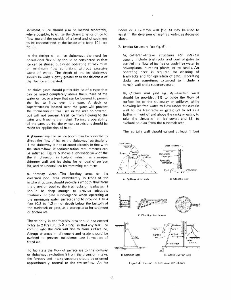
(b) Curtain wall (see fig. 4) .-Curtain walls should be provided: ( 1) to guide the flow of surface ice to the sluiceway or spillway, while allowing ice-free water to flow under the curtain wall to the trashracks or gates; (2) to act as a buffer in front of and above the racks or gates, to take the thrust of an ice cover; and (3) to exclude cold air from the trashrack area.
The curtain wall should extend at least 1 foot
A. Spillway drum gate B. Staplog weir
~-_--~ --~-·· --- ---·-- -- ~-
' "
C. Floating ice booms
D. Skimmer wall E. Intake curtain wall
Figure 4. Ice control features. 101-D-627
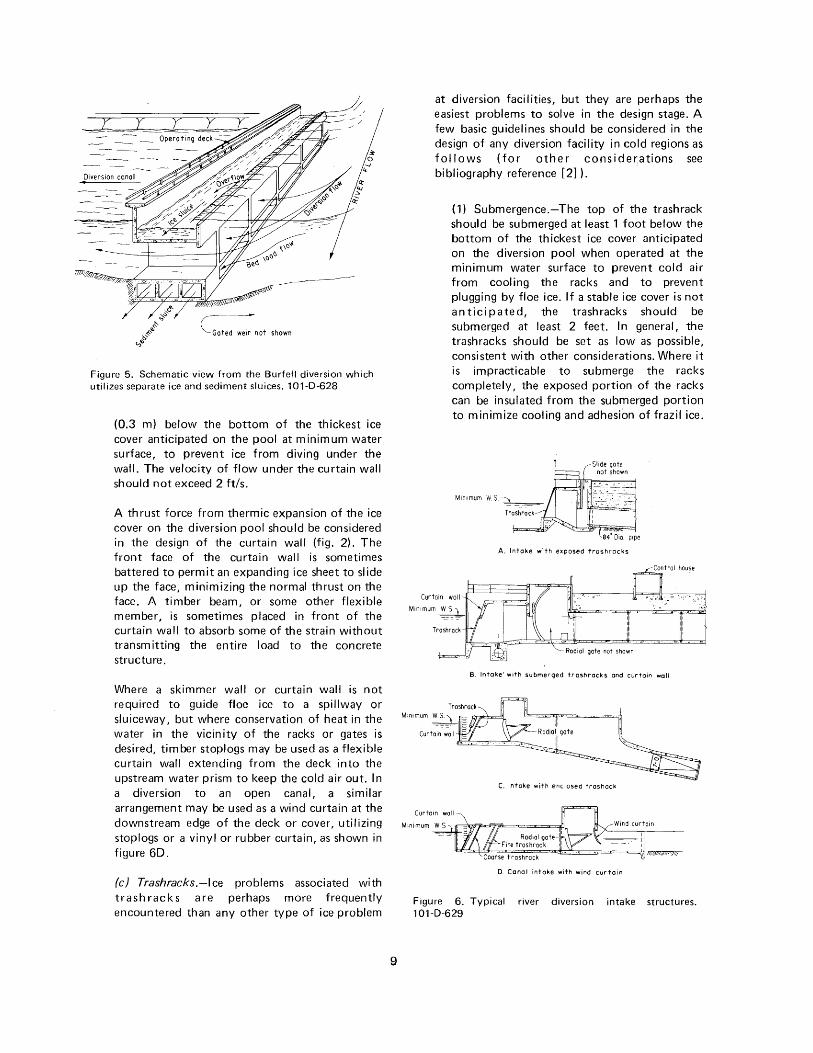
Figure 5. Schematic view from the Burfell diversion which utilizes separate ice and sediment sluices. 101-D-628
(0.3 m) below the bottom of the thickest ice cover anticipated on the pool at minimum water surface, to prevent ice from diving under the wall. The velocity of flow under the curtain wall should not exceed 2 ft/s.
A thrust force from thermic expansion of the ice cover on the diversion pool should be considered in the design of the curtain wall (fig. 2). The front face of the curtain wall is sometimes battered to permit an expanding ice sheet to slide up the face, minimizing the normal thrust on the face. A timber beam, or some other flexible member, is sometimes placed in front of the curtain wall to absorb some of the strain without transmitting the entire load to the concrete structure.
Where a skimmer wall or curtain wall is not required to guide floe ice to a spillway or sluiceway, but where conservation of heat in the water in the vicinity of the racks or gates is desired, timber stoplogs may be used as a flexible curtain wall extending from the deck into the upstream water prism to keep the cold air out. In a diversion to an open canal, a similar arrangement may be used as a wind curtain at the downstream edge of the deck or cover, utilizing stoplogs or a vinyl or rubber curtain, as shown in figure 60.
(c) Trashracks.-1 ce problems associated with trashracks are perhaps more frequently encountered than any other type of ice problem
9
at diversion facilities, but they are perhaps the easiest problems to solve in the design stage. A few basic guidelines should be considered in the design of any diversion facility in cold regions as f o II o w s ( f o r o t h e r co n s i d e r, a t ions see bibliography reference [2]).
( 1) Submergence.-The top of the trash rack should be submerged at least 1 foot below the bottom of the thickest ice cover anticipated on the diversion pool when operated at the minimum water surface to prevent cold air from cooling the racks and to prevent plugging by floe ice. If a stable ice cover is not anticipated, the trashracks should be submerged at least 2 feet. In general, the trashracks should be set as low as possible, consistent with other considerations. Where it is impracticable to submerge the racks completely, the exposed portion of the racks can be insulated from the submerged portion to minimize cooling and adhesion of frazil ice.
A. Intake with exposed troshrocks
B. Intake' with submerged trashrocks and curtoir> wall
C. Intake with enclosed trashack
D. Canal intake with wind curtain
Figure 6. Typical river diversion intake structures. 101-0-629
(2) Adhesion of ice to trash racks.-The greatest threat to the successful operation of trashracks during the winter is from frazil ice, which flows through out the full depth of the water prism, and when in the active state (see sec. B 1), has amazing adhesive qualities. The adhesion of frazil ice to objects such as trashracks varies with the coefficient of thermal conductivity of that object. Thus, its adhesion to steel bars is much greater than its adhesion to wood or plastics, for example [23].
"' Most trashracks are made of steel, for structural reasons, and are quite vulnerable to plugging by frazil ice. The most satisfactory solution to the problem of plugging is to heat the trash racks as discussed in section C7.
(3) Velocity.-The permissible velocity of flow through trash racks is based upon many factors, such as the type of trash anticipated, and the method of cleaning racks. In general, the trash racks should be designed for as low a velocity as economically justified, to minimize head losses and to facilitate cleaning.
The design velocity based upon the gross area of the racks usually ranges from 2 to 2.5 ft/s (0.6 to 0.8 m/s) where racks are cleaned by hand raking, and from 3 to 4 ft/s (0.9 to 1.2 m/s) where power raking is used. A velocity greater than 3 ft/s should be used with caution.
High-pressure intakes are sometimes designed for velocities up to 10 to 12 ft/s (3.0 to 3. 7 m/s) providing the greater head loss is acceptable and the racks are properly designed for vibration [24].
(4) Bar spacing.-The optimum spacing of bars in trashracks is a function of the type of material to be excluded from the downstream facilities, the minimum size of openings in turbines or pumps, and the risk involved in permitting oversized objects to pass through the trashracks.
While the probability of the racks becoming plugged is less by using a greater bar spacing, the possibility of damage to downstream facilities is greater. Many hydro stations having medium-size turbines with runner diameters of 100 to 200 inches (2.5 to 5 m) have operated sucessfully with a clear spacing
10
of 3 to 6 inches (7 .6 to 15 em) between bars; and for the larger turbines having runner diameters of 200 to 300 inches (5 to 7.5 m), a clear spacing of 6 to 10 inches ( 15 to 25 em) has been satisfactory [24] . Some diversion facilities are operated with fine racks in the summer and coarse racks with as much as 20 inches (50 em) of spacing in the winter; while others are operated by removing the racks in the winter, risking damage downstream. A great amount of inactive frazil ice can be passed through the racks and turbines without damage, but the prospect of the racks becoming completely plugged with active frazil ice is much greater if the bars are closely spaced.
(5) Segmented trashracks.-Where it is not practicable to provide good submergence of the trashracks, it is sometimes advisable to provide segmented racks [25] . The middle section can be removed to permit free flow while the upper section retains floe ice, and the bottom section retains anchor ice.
(6) Design loads.-ldeally, the trash racks should be designed to withstand the full hydrostatic load when completely plugged. However, because of the expense involved, they are usually designed for a partially plugged condition.
The thrust force from thermic expansion of an ice cover should not be imposed on the racks, but on the curtain wall above, provided the racks are submerged.
(7) Heating of trashracks (see fig. A-6).-A few basic precepts concerning heating of trash racks shou I d be carefully considered as follows (for a detailed discussion of heating trashracks see bibliography reference [2] ).
F razi I ice poses the greatest threat to trashracks, which may be submerged sufficiently to preclude problems with surface ice. The property of active frazil ice to accumulate and to adhere tenaciously to metalwork makes it a serious problem to the operation of water intakes with trashracks.
Heating of trashracks is effective only if initiated early enough to raise the temperature of the racks above 32° F (0° C) before they contact the frazil ice. It is impossible to melt the ice by heating the trashracks, but by
heating them to a fraction of a degree above the freezing point of water, frazil ice will not adhere to the bars.
(d) Diversion gates.-Spillway gates, sluiceway gates, and headgates are all susceptible to freezing and becoming inoperable, as the result of frazil ice adhering to gates. Unless these gates are well submerged, both upstream and downstream, it is necessary to provide heat to the gates and guides to prevent freezing.
Radial gates are usually heated by applying heat directly to the gate and by embedding a heating cable behind the wallplates and sillplate, as shown in figures A-8 and A-9. Slide gates are heated by providing a heating cable attached to the gate frame, as shown in figure A-7.
It is usually impracticable to design spillway and sluiceway gates to withstand the impact load of large ice floes, but an effort is made to operate the gates fully open when passing such floes. Submersible gates, such as the drum gate (see fig. 4), can be lowered enough to allow the ice to flow over the gate, while wasting only a minimal amount of water.
(e) Superstructure.-A superstructure can be a valuable asset to winter operation of a diversion intake. In addition to preventing the formation of frazil and anchor ice in the area covered, it facilitates the heating process by enclosing the gate area and mm1m1zmg heat losses. A superstructure may also facilitate the success of personnel engaged in operation of gates, cleaning of trash racks, and maintaining equipment during severe weather conditions.
The superstructure, in conjunction with a curtain wall, can provide a warm air space above the trashracks or gates. Where the intake structure discharges to an open canal, a downstream curtain wall, or a vinyl or rubber wind curtain is necessary to keep the cold air out.
Provision should be made to heat the structure as required. A small amount of heat provided below the operating deck should facilitate trouble-free operation. The walls and ceiling of the structure are sometimes insulated to conserve heat.
Where a superstructure is not considered to be justified, a deck should be included above the racks and gates to prevent the formation of frazil
11
and anchor ice on the gates and racks, and to conserve heat, as shown in figure 4.
8. Drop-inlet Structures (See fig. A-5).--
(a) Generai.-Many shallow river diversions are made at high elevations from small streams that have little or no flow during the winter months. Yet, the feasibility of the system may depend upon diverting all the water legally permitted by extending the diversion season through use of special design and operational techniques.
(b) Diversion pooi.-Some drop-inlet diversion facilities are operated without a diversion pool. This may result in formation of anchor ice and frazil ice on the horizontal trashracks, blocking the flow to the intake. A weir structure is sometimes used to form a diversion pool to permit formation of an ice cover precluding production of frazil and anchor ice under the cover.
(c) Weir structure.-A simple weir structure, using flashboards or stoplogs to establish a diversion pool, can provide the flexibility needed to operate a diversion from a small stream. Additional logs can be used during the winter months to provide good submergence or to form an ice cover.
While frazi I and anchor ice do not form under an ice cover they may flow into the diversion pool under the ice. The weir structure should be capable of checking (raising) the diversion pool to an elevation sufficient to result in an ice-covered pool length of at least 100 to 200 feet (30 to 60 m). Thus, the active frazi I ice flowing into the diversion pool has time to become inactive.
(d) Intake structure.-The drop-inlet structure usually features horizontal trashracks coinciding with the invert of the stream. When the streamflow is small, all the flow may drop into the underground forebay pool where required bypass flow and diverted flows are established by appropriate gate openings. The underground structure (fig. A-5) provides an excellent means of conserving any available heat in the plus 32° F (0° C) water.
Assuming that supercooled water flows into the diversion pool, it would soon reach a temperature of 32° F (0° C) as any production of ice would result in a slight temperature increase due to heat of fusion. Gates may have
sufficient submergence to prevent freezing. However, prov1s1on for heating should be included to insure operability.
(e) Trashracks.-lt may be desirable to provide coarse racks (wide bar spacing) during the winter months, since fine racks are more susceptible to plugging with ice.
9. Diversion to Open Canals (see fig. 1 ).-
(a) Generai.-After ice-free water is diverted to penstocks, discharge lines, or some other closed conduit, the problems associated with winter operation are usually over. However, where the diversion is made to an open canal, for conveyance to a powerplant, pumping plant, or water supply system, ice-related problems are still a threat to successful operation.
Two distinct types of operation are used for such power canals or headrace canals: ice-free operation and ice-covered operation. The choice between ice-free and ice-covered operation may be complex, depending upon the temperature of the diverted water, climatic conditions, and the ability to divert ice-free water from the river.
(b) Avoidance of frazil ice and anchor ice production .-Regardless of the designer's plan to operate ice free or with an ice cover, every effort should be made to minimize the production of frazil ice and anchor ice in the canal. This can be facilitated as follows:
( 1) Avoid turbulence in the canal by streamlining transitions to and from canal structures.
(2) Provide concrete or timber covers over structures in which turbulence is unavoidable.
(3) If necessary, provide a sedimentation section at the upstream end of the canal for silt removal (fig. 1).
(4) Use a narrow, deep, canal prism to minimize formation of frazil and anchor ice [26].
(5) Where practical, provide a hydraulic section with a velocity of 2 ft/s or less to encourage formation of an ice cover, and to insure that any frazil ice formed in an open reach will rise to form surface ice.
12
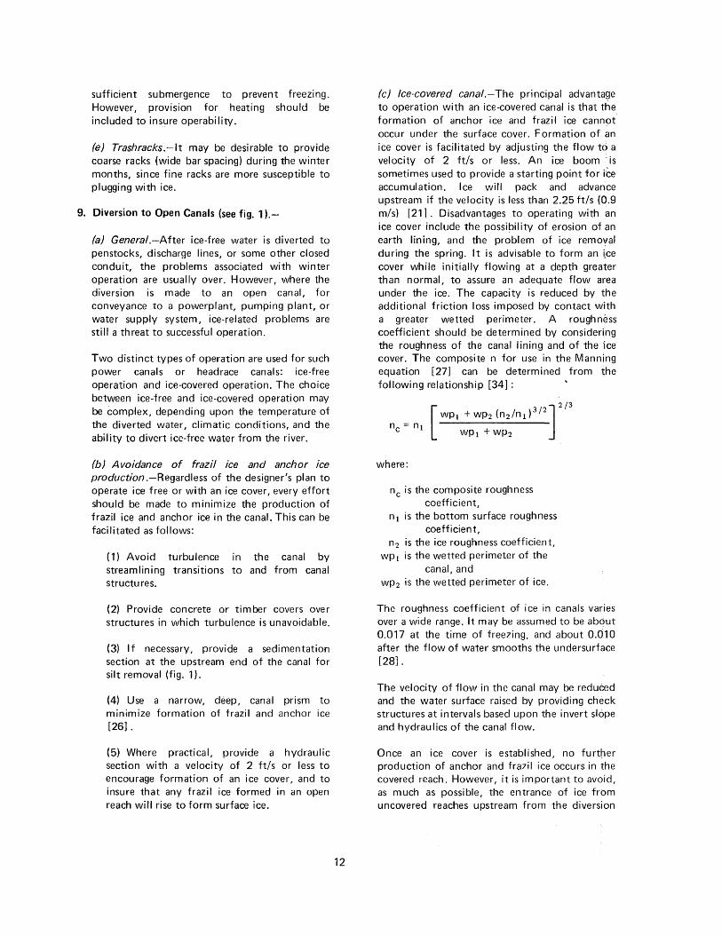
(c) Ice-covered canal.-The principal advantage to operation with an ice-covered canal is that the formation of anchor ice and frazil ice cann9t occur under the surface cover. Formation of an ice cover is facilitated by adjusting the flow to a velocity of 2 ft/s or less. An ice boom is sometimes used to provide a starting point for ice accumulation. Ice will pack and advance upstream if the velocity is less than 2.25 ft/s (0.9 m/s) [21] . Disadvantages to operating with an ice cover include the possibility of erosion of an earth lining, and the problem of ice removal during the spring. It is advisable to form an i;ce cover while initially flowing at a depth greater than normal, to assure an adequate flow area under the ice. The capacity is reduced by the additional friction loss imposed by contact with a greater wetted perimeter. A roughness coefficient should be determined by considering the roughness of the canal I ining and of the ·ice cover. The composite n for use in the Manning equation [27] can be determined from the following relationship [34]:
where:
nc is the composite roughness coefficient,
n 1 is the bottom surface roughness coefficient,
n2 is the ice roughness coefficient, wp 1 is the wetted perimeter of the
canal, and wp 2 is the wetted perimeter of ice.
The roughness coefficient of ice in canals varies over a wide range. It may be assumed to be about 0.017 at the time of freezing, and about 0.010 after the flow of water smooths the undersurface [28].
The velocity of flow in the canal may be reduced and the water surface raised by providing check structures at intervals based upon the invert slope and hydraulics of the canal flow.
Once an ice cover is established, no further production of anchor and frazil ice occurs in the covered reach. However, it is important to avoid, as much as possible, the entrance of ice from uncovered reaches upstream from the diversion
structure (see letter in appendix II A concerning ice problems at Prosser Powerplant on the USBR Yakima project).
(d) Ice-free cana/.-lt is sometimes desirable to design a canal for ice-free operation. Several factors should be considered as follows:
( 1) Water temperature.-The diverted flow from most shallow river diversions is at a temperature of 32° F (0° C) or slightly higher. However, some diversion flows may have a temperature high enough to avoid freezing. The water temperature drop in the canal can be determined approximately for various weather and hydraulic conditions by using the equations in appendix I. It can then be estimated how far the water will flow in the canal without formation of ice.
(2) Velocity.-lt has been found [4J that surface ice will not form on a canal flowing in excess of 6.5 ft/s (2 m/s). Thus, any ice entering a canal, and any frazil or anchor ice that is formed in a canal with such a high velocity will flow freely to the forebay downstream.
It should be emphasized that production of frazil and anchor ice in the canal should be minimized by observing the design considerations listed in section C9(b).
(e) Canal forebay.-Canals that carry diversion flows to powerplants or pumping plants should terminate in a forebay just upstream from the plant. The forebay should serve to transition the flow of ice-free water to the plant while channeling ice or ice-laden water to a spillway or sluiceway.
The forebay should be large enough to provide a maximum velocity of about 1.5 ft/s (0.5 m/s) to facilitate the formation of an ice cover. The ice cover should be at least 100 to 200 feet (30 to 60 m) long to permit active frazil ice (which may flow under the surface cover) to become inactive before reaching the trash racks.
The forebay should be oriented to flow direct to the spillway or ice sluice to facilitate removal of ice. Flow to the powerplant or pumping plant should be transitioned smoothly to the right or left of the canal alinement. See sections C4 and C5 for design considerations concerning spillways and sluiceways.
13
A skimmer wall or an ice boom should be provided to channel the flow of ice to the spillway or sluiceway. The skimmer wall may be incorporated in the design of the intake structure as a curtain wall.
(f) Intake structure. -See section C7 for design considerations concerning the intake structure. The major considerations are listed as follows:
( 1) Trash rack submergence
(2) Trashrack bar spacing
(3) Segmented trashracks
(4) Velocity through trashracks
(5) Heating of trashracks and gates
(6) Covered intake structure
(7) Sediment trap upstream from trashracks
10. Bubbler Systems.-Bubbler systems have been used successfully on many projects to maintain ice-free water surfaces [ 16] . The success of any bubbler system, however, is dependent upon the presence of warm water, over 32° F (0° C), which can be circulated to melt or prevent formation of surface ice. As shallow rivers do not ordinarily have a significant reserve of warm water, bubbler systems used in conjunction with shallow river diversions would be of doubtful value, except that they have been effective in retarding the formation of surface ice by causing agitation of the water.
D. OPERATION OF SHALLOW RIVER DIVERSIONS
1. River ControL-Where the water temperature of a river can be controlled by selective withdrawal from an upstream reservoir, using high- and low-level outlets, it may be possible to conserve the warmer water in the reservoir, using it only when needed to facilitate trouble-free operation of a downstream diversion structure. With such a provision, the release of warm water from the low-level outlet may slow the rate of the water temperature drop sufficiently to prevent the formation of frazil ice.
Where an upstream control is not provided, it may be desirable to inundate frazil-producing rapids by constructing a weir downstream, thus eliminating the rapids and most of the frazil ice. The weir itself
may cause sufficient turbulence to perm it formation of frazil ice unless a deck is provided over the weir. On a small stream, the weir can be comprised of stoplogs, which can be removed before the heavy spring flows occur.
2. Diversion Pooi.-When the water temperature drops to or near 32° F (0° C), the water surface in the diversion pool should be checked up to provide a slow velocity of 1.5 ft/s or less, permitting formation of an ice cover at a high water surface elevation. The formation of such a cover can be expedited by shutting down the plant on the first night that is sufficiently cold to form an ice cover. Care should be used to avoid rapid fluctuations in water depth to avoid rupturing the ice cover.
As the ice cover thickens and the flow area diminishes, the velocity will increase. As long as the velocity is 2 ft/s or less, any frazil ice produced upstream will rise and add to the thickness of the ice cover. When the cover becomes so thick that the velocity is greater than 2 ft/s (0.6 m/s), the frazil ice produced upstream will be carried through the pool to the trash racks.
The flow of frazil ice to the trashracks constitutes a serious problem only if it is in the active state (see sec. B1). By providing an ice cover of at least 100 to 200 feet (30 to 60 m), the active frazil ice entering the pool under the ice cover will have sufficient time to become inactive (and usually harm less) before reaching the trashracks. An enormous amount of inactive frazil ice may flow through the plant without adverse effects [35] .
3. Spillway.-Where an adjustable spillway crest is provided, the diversion pool water surface can be adjusted to accommodate diversion head requirements. In general, the operating water surface should be raised as high as possible before forming an ice cover.
When an excess of ice accumulates in the diversion pool, the spi II way gates or stop logs should be adjusted to flush out the excess ice.
When large ice floes occur in the river, an effort should be made to operate the spillway gates fully open, as it is usually impracticable to design the gates to withstand the impact load from such floes. Ice floes may pass over submersible gates without damage. See section C7(d) for gate heating requirements.
14
When the thrust force due to thermic expans'ion threatens to damage the spillway structure or gates, an effort should be made to remove or prevent formation of ice adjacent to the structure. This can be accomplished with a bubbler system if 'the diversion pool is large and deep enough to provide sufficient heat in the lower depths of the pool. However, this is not usually possible for shallow river diversions which normally have a small shallow diversion pool.
Some operating personnel have solved the problem of excess pressure on the structure by cutting a slot in the ice in front of the structure, and filling,the slot with logs and straw. If the face of a structure is battered, the sloping surface will permit the ice to slide up the sloping face thereby relieving ·the pressure.
4. Ice Sluiceway.-! t may be necessary to open the sluice gate whenever an excess of ice ·has accumulated in the diversion pool, but particu~arly during the spring breakup of river ice. If a skirnmer wall is not provided, an ice boom should be constructed to channel the flow of river ice tq the ice sluiceway. Frequent operation of unheated gates may keep them from freezing.
5. Forebay.-A skimmer wall or ice boom may be constructed to prevent ice floes from entering the forebay area provided sedimentation problems do not result. Where an ice cover does not readily form on the forebay area, its formation can be initiated by placement of wooden beams or screens in front of the intake structure. Floating· on the water surface, the beams not only accelerate formation of an ice cover but also serve to interrupt any vortex that may otherwise form in front of the trashracks, which would pull cold air down to the racks. The formation of an ice cover can also be initiated by seeding the forebay with dry ice [29].
6. Intake Structure.-Several procedures can be used to facilitate trouble-free operation of the intake structure as follows:
(a) Trashrack submergence.-lf possible,. the spillway, sluiceway, and head gates shoulc;l be operated to maintain at least 2 feet of submergence over the top of the trashracks, to prevent ice formation on the racks.
(b) Trashrack cover.-Where it is not practicable to provide adequate trashrack submergence; and
where a superstructure or a structural cover is not provided, a concrete or wooden cover should be constructed over the racks to prevent cold air from contacting them. The cover should include a curtain wall upstream from the racks to exclude cold air. If the diversion structure discharges to an open section, a downstream curtain is also required. This can be of rubber, vinyl, or any other material that can effectively keep the cold air out.
The space so covered may be heated with a space heater if required, but it is sometimes sufficient to insulate the cover. A removable deck panel may be required for cleaning of trashracks or operation of gates.
(c) Trash rack heating (see Prevention of Water In take Clogging by Application of Heat [2]).-The proper application of heat to trashracks is the surest method of preventing their clogging by frazil ice. It is not necessary to heat the racks every time the water temperature drops to the freezing point, as frazil ice does not form unless the rate of cooling exceeds 0.018° F. (0.01 ° C) per hour between the temperatures of 32.18° F and 32° F (0.1° C and 0.0° C) [5].
A thermoregulator such as the Temp-Tact No. 2290/602A, which has a sensitivity of 0.009° F (0.005° C), could be used to monitor the rate of cooling and initiate heating as required. Heating can be terminated when the supercooled water returns to a temperature of 32o F (OO C).
Logan [2] describes methods of heating trashracks and determines the amount of heat that is required.
(d) Removal or replacement of trashracks.-Where ice problems persist in spite of other precautionary procedures, it is sometimes necessary to remove the trashracks, taking a calculated risk that ice passing through the intake structure will not damage the downstream installation. Instead of removing trashracks completely, they are sometimes removed in sections [25]. This is most effective where the midsection can be removed, leaving the upper and lower sections in place to intercept the flow of frazil ice or anchor ice.
It is sometimes advantageous, during the winter months, to replace the steel trashracks with
15
wooden or plastic-coated racks, which are less susceptible to adhesion by frazil ice and its attendant plugging. Trashracks with a small bar spacing are sometimes replaced by racks having a greater bar spacing, permitting more ice to pass, but reducing the threat of plugging. Double screens have also been used, with the upstream screen providing a wide bar spacing (6 to 20 inches) and the downstream screen with a standard bar spacing.
7. Operation of Canals.-
(a) Generai.-Water supply canals are operated ice free or ice covered, depending upon the heat available in the water diverted to the canal, the severity of weather conditions, the velocity of flow, and other factors.
(b) Operation of ice-free canal.-lce-free operation is often maintained in the upstream reach of a canal having a water temperature in excess of 32° F (0° C). The length of flow that is required for the water temperature to drop to 32° F (0° C) can be computed, approximately, by the equations in appendix I. Downstream from this point, a cover of surface ice will form unless the velocity of flow is too great.
To avoid production of frazil ice in an ice-free canal, it is important to avoid turbulence as much as possible. Where turbulence occurs, the production of frazil ice can be prevented by construction of a concrete or timber cover over the turbulent reach. Where blowing snow enters the canal and increases the formation of frazil ice, it may be necessary to construct a snow fence.
When a considerable amount of frazil ice or floe ice enters the canal at the diversion structure or is formed in the canal, it may be necessary to flush some of the ice out of the canal at wasteways or at the terminal fore bay. A large volume of water is usually required to flush the ice out. It may be necessary to heat wasteway or check gates, to ensure operability.
In ice-free operation, the accumulation of ice at canal structures may require removal by use of power equipment such as a clamshell, dragline, or shovel. The thin sliver of ice that first forms along the sides of a canal has been removed before it attains significant proportions by mounting a power shovel on a flat-bed truck and
traveling along the operating road, with the shovel bucket extending to the water prism, fracturing the ice into small pieces.
(c) Operation of ice-covered canal.-The reach of canal that is to be operated with an ice cover should preferably be checked to flow at a velocity of 2 ft/s or less to facilitate formation of an ice cover. The checked water surface should be sufficient to permit operation under the ice, recognizing that the increasing ice thickness will gradually diminish the flow area, and that the additional wetted perimeter (see sec. C9) will increase the frictional resistance to flow. Thus, it is common practice to check the water surface at least 1 foot above normal.
The adjustment of gates or valves should be gradual to avoid excessive fluctuations in the water surface, which may rupture the ice cover. Since it is almost impossible to produce an ice cover that is self-supporting in a trapezoidal canal, it is necessary to operate the gates and valves to maintain a flow surface in contact with the ice cover.
An inflow of ice from the diversion structure should be avoided if possible. While inactive frazil ice can normally flow through an ice-covered canal without harm, it has in some instances deposited, starting in slow-velocity areas, in sufficient proportions to completely block the canal prism. Particular care should be used to exclude ice from a canal that flows into a small reservoir or lake, as evidenced by a letter from Mr. Lindgren concerning "Ice Trouble at Prosser Powerplant-Yakima Project," (see appendix II).
(0.005° C), above and below freezing, the heat supply to trashracks and gates can be turned on automatically when the rate of cooling indicates the imminent formation of frazil ice (see sec. B 1 (b)).
E. RECOMMENDATIONS FOR FURTHER RESEARCH
1. Shallow River Diversions in GeneraL-A standard-type diversion structure, utilizing the features described in section C, should be modeled in the laboratory to determine: (a) optimum velocities for spilling ice, sluicing ice, diverting ice-free water, and (b) the configuration and range of flow direction changes that can best exclude ice and sediment. This could be performed in conjunction with a specific diversion. The distance required for active frazil ice to become inactive should be determined for a range of velocities.
2. Model Study of a Specific Diversion Facility.-A model study of a drop-inlet-type diversion should be performed to determine the best configuration to avoid ice, trash, and sediment.
3. Monitor and Control Equipment.-A package should be assembled for use in the laboratory and at project sites as required to monitor water temperature and control trashrack heating equipment. This package should include:
(a) A precise water temperature gage, accurate to 0.009° F (O.Oo5o C)
(b) Water temperature recording equipment
(c) Rate-of-cooling equipment
(d) Automatic heat controls (with manual
When the spring breakup occurs, the resulting override) floe ice should be flushed from the canal at wasteways or sluiceways. A considerable volume F. GLOSSARY OF TERMS of water is usually wasted in flushing the ice from the canal. 1. Anchor Ice (Bottom lce).-lce which is formed
on the bottom of shallow streams or canals 8. Monitoring and Control Equipment.-Where a diversion facility is not provided with equipment to monitor hydraulic pressure head upstream and downstream from the trashracks, operators may wish to provide this equipment to reflect the degree of trashrack plugging.
The water temperature should also be monitored. By using sensitive equipment such as the Temp-Tact Thermoregulator, which is accurate to 0.009° F
16
attaching itself to rocks or structures.
2. Floe Ice (Float lce).-Broken pieces of sheet ice flowing in blocks of random size and shape, floating on the water surface.
3. Frazil Ice (Needle lce}.-A crystalline form of ice that forms throughout the body of supercooled, turbulent water, accumulating in large spongy masses.
4. Sheet Ice (Surface lce}.-Sol id ice, formed on the water surface.
5. Slush lce.-An unconsolidated or unsolidified mixture of ice which may include frazil ice, anchor ice, snow, or small pieces of surface ice.
6. Supercooled Water.-Water that has been cooled below its normal freezing temperature, without solidifying.
G. BIBLIOGRAPHY
[ 1] (26) * "Ice Problems in Winter OperationsRecommendations for Research," Bureau of Reclamation, 1971.
[2] Logan, T. H., "The Prevention of Frazil Ice Clogging of Water Intakes by Application of Heat," U.S. Bureau of Reclamation R EC-E RC-74-15, 1974.
[3] Barnes, H. T., "Ice Engineering," 1928.
[4] (5) Ruths, A., "Ice Troubles in Norwegian Water Powerplants," Trans, First World Power Conference, 1924.
[5] (1) Granbois, K. J., "Combatting Frazil Ice in Hydroelectric Stations," Transactions of the American Institute of Electrical Engineers, April 1953.
[6] (16) Carstens, T., "Heat Exchangers and Frazil Formation," International Association of Hydraulic Research (IAHR), Ice Symposium, 1970.
[7] (23-o) Hausser, R., and Beauchemin, R., "Rate of Ice Production on an Open Water Surface," IAHR, vol. 3, 8th Congress, Montreal, 1959.
[8] (3) Devik, 0., "Present Experience on Problems Connected With the Utilization of Water Power in Norway," IAHR, Journal of Hydraulic Research, No. 2, 1964.
[9] ( 15-a) Mosonyi, E., 'Water Power De-velopment (Chapter 29) ," 1963.
[10] (4) Samsioe, A. F., "Measures Taken in Sweden Against Ice Troubles at Water Powerplants," Trans, First World Power Conference, 1924.
[ 11] ( 19) Carstens, T ., "Experiments With Supercooling and Ice Formation in Flowing Water," Geophysica Norwegica, vol. XXVI, No. 9, 1966.
[12] (17) Williams, G. P., "Adhesion of Frazil Ice to Underwater Structures," Proc 24th Eastern Snow Conference, 1967.
[13] (7) Scherman, K. A., "On Ice Difficulties of Open Water Courses of Hydro-electric Plants," IAHR, vol. 3, 8th Congress, Montreal, 1959.
[14] (98) Deslauriers, C. E., "Projects to Alleviate Ice Jams on the Chaudiere River in Quebec," Proc 22nd Eastern Snow Conference, 1965.
[ 15] (23-1) Pari set, E., and Hausser, R ., "Evolution of Ice Covers During Their Formation," IAHR, vol. 3, 8th Congress, Montreal, 1959.
[16] (48-a) Williams, G. P., "Thermal Regime of Lakes and Rivers With Reference to Air Bubbling Systems," Proc of Symposium on Air Bubbling, Atlanta, 1961.
[17] (20) Jarocki, W., "Relationship of Air Temperature to the Occurrence of Frazil Ice and Ice Floes in Rivers," Prague Institute Techniki, 1966.
[18] (23-m) Pari set, E., and Hausser, R ., "Formation of Ice Covers on Rivers," IAHR, vol. 3, 8th Congress, Montreal, 1959.
[19] (23-c) Beccat, R., and Michel, B., "Thrust Exerted on a Retaining Structure by Unconsolidated Ice Covers," IAHR, vol. 3, 8th Congress, Montreal, 1959.
[20] "Design Standards No. 3, for Canals and Related Structures," U.S. Bureau of Reclamation, 1967.
[21] (100) Cousineau, J. E., "Some Aspects of Ice Problems Connected With Hydroelectric Developments," Proc 17th Eastern Snow Conference, 1960.
[22] Johnson, P. L., "Hydraulic Model Studies of the Forebay Reservoir Inlet-Outlet Structure for Mt. Elbert Pumped-Storage Powerplant," U.S. Bureau of Reclamation, REC-ERC-72-5, 1972.
*Numbers in parentheses refer to the USBR Ice Technology Library number.
17
[23] (6) Williams, G. P., "Frazil Ice-A Review of Its Properties With a Selected Bibliography," Engineering Journal, vol. 60, 1959.
[24] (36) Zowski, T., "Trashracks and Raking Equipment," Water Power, Sept 1960.
[25] (15b) Mosonyi, E., "Water Power Development (Chapter 24) ," 1963.
[26] (41) Wilson, R. M ., "Design of Hydro-electric Plants for Combatting Ice Troubles," Journal of the Engineering Institute of Canada, May 1919.
[27] King, H. W., "Handbook of Hydraulics," Fifth Edition, 1969.
[28] Chow, W., ~~open-channel Hydraulics," 1959.
[29] (13) Schaefer, V. J., "The Formation of Frazil and Anchor Ice in Cold Water," Trans Am. Geophysical Union, vol. 31, No.6, 1950.
[30] Glover, R. E., et al, "Winter Operations-Power . Plants" unpublished USBR report, 117,627
55A, 1952.
18
[31] (23-q) Williams, G. P., "An Empirical Method of Estimating Total Heat Losses from Open Water Surfaces," IAHR, vol. 3, 8th Congress, Montreal, 1959.
[32] Shul'gin, A. M., "The Temperature Regime of Soils," translation from Russian for Department of Agriculture, 1965.
[33] letter from Yakima Project office, May 29, 1973
[34] "Factors Influencing Flow in Large Conduits," Proc American Society of Civil Engineers, Journal of the Hydraulics Div., vol. 91, No. HY6, November 1965.
[35] ( 122) Townsend, D. R., "Control of Ice Jams at Barrett Chute G. S.," Proc American Society of Civil Engineers, Journal of the Power Div., vol. 97, No. P03, July 1971.
[36] Michel, Bernard, "Ice Pressure on Engineering Structures", CR R E L Science and Engineering Monograph 111-B 1 b, June 1970.
APPENDIX I
Heat Loss Factors
1. General.-The water temperature at diversion structures, powerplants, and pumping plants is affected by upstream conditions such as reservoirs, canals, tunnels, and pipelines. Heat loss factors relating to water conveyance systems will be the subject of a future report. However, a few rules-of-thumb, evaluating some of the variables which influence the water temperatures are presented briefly, and approximate solutions offered. In some cases, a more precise determination may not be justified, as, for example, a wind velocity of 10 miles per hour (mi/h) ( 16.1 km/h) can triple the heat loss from an open water surface [ 16] .
2. Reservoirs.-The heat available in a storage reservoir is the product of several factors such as the water temperature profile, the heat gain from solar radiation, and the heat loss from reservoir inflows and outflows.
(a) Water temperature profi/e.-Water has its maximum density at a temperature of 39.2° F (4° C). Thus, following the autumnal turnover, when the coldest water rises to the surface of a reservoir, the warmest water (with a maximum temperature of 39.2° F (4° C)) sinks to the bottom.
By providing a reservoir outlet structure with ports at several elevations, water can be discharged from either the colder zone or the warmer zone. Thus, using selective withdrawal, the discharge from the reservoir can be regulated to conserve heat using warm water only when it is necessary to avoid ice problems.
(b) Heat gain in reservoir.-Two factors contribute to a heat gain in reservoirs during the winter as follows [30] :
( 1) Solar radiation.-G lover indicates that the daily solar radiation reaching the surface of Lake Estes (el. 7475) on the USBR Colorado Big Thompson project amounts to about 830 Btu per square foot during the winter months. Only one-fourth of the radiation penetrates through the water surface or clear ice surface to the lower depths to produce a heat gain. With a snow cover on the ice, the effective radiation is reduced considerably. It is reasonable to assume that in any one day no more than 100 Btu per square foot penetrates the snow-covered ice.
19
(2) Ground temperature.-A lesser heat gain results f:-om the relatively warm bottom surface of the reservoir. The soil or rock surface may have a temperature ranging from about 45° to 550 F (7° to 13° C) .
(c) Heat loss from reservoir.-The direct loss of heat from the reservoir to the atmosphere is very small after an ice cover is formed. However, a significant cooling effect occurs as water flows into the reservoir at a temperature near 32° F (0° C) and out of the reservoir at a higher temperature.
3. Canals.-The many variables which affect the heat loss from canals and streams preclude a precise determination in most instances. For example, a wind velocity of 10 miles per hour ( 16 km/h) will increase the heat loss from an open water surface from about 3 to about 8 Btu per square foot per hour per degree Fahrenheit (17 to 45 W/m 2 /°C).
To include all heat losses, G. P. Williams [31] shows a total heat Joss factor based upon observations (with an 8-m ile-per-hour wind) of:
7 Btu per square foot per hour (22 W /m 2), per
degree centigrade
or about
4 Btu per square foot per hour ( 12 W /m 2), per
degree Fahrenheit
Williams [12], Scherman [13], and Michel [36] offer a more complete analysis based upon radiation, convection, and evaporation for use where a more precise heat Joss determination is required. Williams [23] illustrates these factors for streamflow in figure A-1.
The total heat loss from a canal may be approximated as follows:
Loss = C(6t)
C(6t)
3,600
Btu per square foot per hour
Btu per square foot per second
C(D.t)W Btu per foot of canal per second
3,600
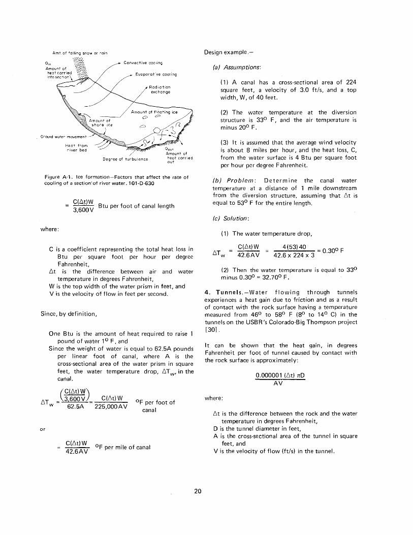
Amt. of falling snow or rain
Convective cooling
Evaporative cooling
Radiation exchange
Ground-water movement
Heat from river bed
Degree of turbulence
Figure A-1. Ice formation-Factors that affect the rate of cooling of a section'of river water.101-D-630
C(Llt)W Btu per foot of canal length 3,600V
where:
C is a coefficient representing the total heat loss in Btu per square foot per hour per degree Fahrenheit,
6t is the difference between air and water temperature in degrees Fahrenheit,
W is the top width of the water prism in feet, and V is the velocity of flow in feet per second.
Since, by definition,
One Btu is the amount of heat required to raise 1 pound of water 1° F, and
Since the weight of water is equal to 62.5A pounds per I in ear foot of canal, where A is the cross-sectional area of the water prism in square feet, the water temperature drop, 6T w• in the canal.
(C(6t)W)
6 T = 3,600V C(6t)W w 62.5A 225,000AV
°F per foot of canal
or
C(6t)W
42.6AV °F per mile of canal
20
Design example.-
(a) Assumptions:
( 1) A canal has a cross-sectional area of 224 square feet, a velocity of 3.0 ft/s, and a top width, W, of 40 feet.
(2) The water temperature at the diversion structure is 33° F, and the air temperature is minus 20° F.
(3) It is assumed that the average wind velocity is about 8 miles per hour, and the heat loss, C, from the water surface is 4 Btu per square foot per hour per degree Fahrenheit.
(b) Problem: Determine the canal water temperature at a distance of 1 mile downstream from the diversion structure, assuming that 6t is equal to 53° F for the entire length.
(c) Solution:
( 1) The water temperature drop,
C(6t)W 4(53)40 = O 300 F 6T w = 42.6AV = 42.6 x 224 x 3 .
(2) Then the water temperature is equal to 33° minus 0.30° = 32.70° F.
4. Tunnels.-Water flowing through tunnels experiences a heat gain due to friction and as a result of contact with the rock surface having a temperature measured from 46° to 58° F (8° to 14° C) in the tunnels on the USBR 's Colorado-Big Thompson project [30].
It can be shown that the heat gain, in degrees Fahrenheit per foot of tunnel caused by contact with the rock surface is approximately:
where:
0.000001 (6t) 1rD AV
6t is the difference between the rock and the water temperature in degrees Fahrenheit,
D is the tunnel diameter in feet, A is the cross-sectional area of the tunnel in square
feet, and Vis the velocity of flow (ft/s) in the tunnel.
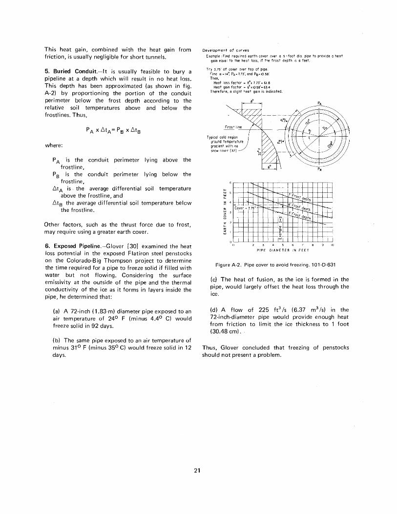
This heat gain, combined with the heat gain from friction, is usually negligible for short tunnels.
5. Buried Conduit.-lt is usually feasible to bury a pipeline at a depth which will result in no heat loss. This depth has been approximated (as shown in fig. A-2) by proportioning the portion of the conduit perimeter below the frost depth according to the relative soil temperatures above and below the frostlines. Thus,
where:
P A is the conduit perimeter lying above the frostline,
P8 is the conduit perimeter lying below the frostline,
6tA is , the average differential soil temperature above the frostline, and
6t8 the average differential soil temperature below the frostline.
Other factors, such as the thrust force due to frost, may require using a greater earth cover.
6. Exposed Pipeline.-Giover [30} examined the heat loss potential in the exposed Flatiron steel penstocks on the Colorado-Big Thompson project to determine the time required for a pipe to freeze solid if filled with water but not flowing. Considering the surface emissivity at the outside of the pipe and the thermal conductivity of the ice as it forms in layers inside the pipe, he determined that:
(a) A 72-inch ( 1.83-m) diameter pipe exposed to an air temperature of 24° F (minus 4.4° C) would freeze solid in 92 days.
(b) The same pipe exposed to an air temperature of minus 31° F (minus 35° C) would freeze solid in 12 days.
21
Development of curves Example: Find required earth cover over a s -foot dio. pipe to provide a heat
gain equo I to the heat loss, if the frost depth is 6 feet.
Try 3.7~' of cover over top of pipe. Find a - 14~ PA- 7.73', and P8 -10.58'. Then,
Heat loss foetor- 8°• 7.73'- 61.8 Heat gain factor - 6°' 10.56'· 63.4
Therefore, a slight heat gain is indicated.
Frost line
Typical cold req1on ground temperature gradient with no snow cover [32)
80
r---. l -....~--. 1-
UJ 5 ..... u.
2: 4
a:: UJ > 2
r---. i-< _ _J_I">-. Cover : 3.75'
r---.~---.,
rs.- -1-
1--r-
--~--- 1' Frost I ~f!Pth
~t-- 6'Fro I f T~th
---~rost I in-~p.::;~~ I 0
r----... =----
.... ,_ :I: 2 1-a:: "'--I-- -I-1-- --r·--
::; I ~ w
0 0 10
PIPE DIAMETER IN FEET
Figure A-2. Pipe cover to avoid freezing. 101-0-631
(c) The heat of fusion, as the ice is formed in the pipe, would largely offset the heat loss through the ice.
(d) A flow of 225 ft 3 /s (6.37 m3 /s) in the 72-inch-diameter pipe would provide enough heat from friction to limit the ice thickness to 1 foot (30.48 em).
Thus, Glover concluded that freezing of penstocks should not present a problem.

APPENDIX II
Experience With Shallow River Diversions in Cold Regions
A. Bureau of Reclamation (USBR) Experience.-AII of the USBR regional offices that have facilities in cold regions were contacted by the Ice Research Study Team in 1971 to determine the extent of their ice-related problems, together with methods used to alleviate such problems. These problems and solutions are included in the 1971 report: [1] /ceProblemsin Winter Operation-Recommendations for Research. Those problems and solutions which relate to shallow river diversions, together with other USBR diversion experiences during cold weather, are described briefly.
1. Prosser Powerplant- Yakima Project-1949.-A letter from 0. W. Lindgren dated March 14, 1949, is quoted as follows:
"a. Whenever temperatures fall below 10° F, ice begins to form in the power canal and it appears in the form of small crystals which float deep in the water. Its characteristic tendency is to adhere to any object it hits and, in a short time, builds up large slushy masses of so-called 'anchor-ice' which completely chokes trashracks and obstructs the flow of water in the canal.
"Beginning on December 27, 1948, and extending to February 16, 1949, ice troubles were experienced without any let up. Costs for ice removal and canal repair work during that period amounted to nearly $10,000, and the loss in power generation was about 2,500,000 kilowatt-hours. This was the worst ice condition ever experienced at the Prosser Powerplant.
"b. Outages between December 27 and 31 were necessary because of a very rapid accumulation of ice which raised the water level, catJsing a break in the canal bank. When service was resumed a natural pond, which forms part of the canal, was frozen over solidly which further obstructed the flow of water. From that time on, it became increasingly difficult to get water through the canal. Temperatures held steadily below freezing for the next 45 days, and a vicious cycle set in whereby the water supply gradually diminished and anchor-ice formed all the more rapidly.
"c. The outage of 36 hours between January 14 and 16 was necessary because a section of steel
*cfs now ft3 /s
23
trashrack, which was loosened by a dragline which was being used for removing ice, fell into the penstock. This shutdown resulted in further freezing over of the ponded area, and by this time the water surface was raised about 18 inches above the normal in an effort to force the water through the canal. This caused leakage through the canal bank at one point of from 5 to 8 cfs*, but since the bank was made largely of broken rock, it did not wash out but considerable concern was had for the safety of the canal.
"d. A critical stage was reached on January 31 when safety links began breaking on the wicket gates which control the flow of water through the turbine. This again required shutting down and draining the canal. The trouble was found to be caused by a broken rake which had gotten into the machine. When the canal was drained slush ice was found to be about 4 feet thick on the bottom of the canal. Upon resumption of service, after 51 hours and 48 minutes shutdown for repair of the turbine, weather conditions began to moderate but ice conditions were then so bad that it took nearly two weeks time to fully clear ice from the canal and get back to normal operations.
"e. These ice problems bring to attention several fundamental weaknesses in the design of the power canal which should be given serious consideration in planning for the proposed Chandler Plant. Suggestions for improvements are as follows:
"( 1) Provide for a liberal overflow capacity of water for flushing ice away from the penstock forebay. The spillway should take off directly from the end of the canal rather than on the same side as the penstock so as to direct the overflow away from the penstock as much as possible. Since the Chandler power canal will be designed to carry water in excess of power requirements, considerable advantage will be gained in that the excess water may be used for flushing ice; however, to effectively flush out the submerged ice, which caused the most trouble, the spillway control should be built with gates which discharge water from underneath.
"(2) Trashracks over the penstock intake should be designed with a mechanical cleaning device for removing ice. The greatest problem is from anchor-ice building up from the bottom_ The only effective way, thus far found, for breaking this ice loose is by vibrating the trashrack, which has been done by hand hammering or jarring with a dragline bucket. The former method is quite ineffective, and the latter damages the trashracks considerably. Any machine designed for ice removal should incorporate both raking and vibrating features. Trashracks should also be securely anchored at the bottom. This is not the case in the present structure so trouble was experienced when the back surge, caused from shutting down the plant, simply lifted ice-laden trashracks out of position.
"(3) The power canal should be concrete I ined throughout its entire length, first, because the lava rock formation, through which it is built, is extremely porous and, second, because the higher velocities permitted in a concrete lined canal will materially mm1m1ze ice formation. The greatest problem in operating the present canal is the effect of dead water in a natural pond which forms a part of the canal. During freezing weather ice forms in this pond and very effectively retards the flow of water. This choking effect causes the water level to rise which develops leaks in the canal bank, directly above the pond. This experience has been repeated many times during the history of operation but this year was the worst. At one time the water level stood about 18 inches above the normal.
"Another bad effect from this pond is the accumulation of si It which is deposited due to the slow velocity of water flowing through it. After the spring flood of 1948, this pond filled up with silt to such an extent that the required flow was maintained with difficulty. The pond should certainly be eliminated in any future construction.
"(4) The formation of ice on the headgates is another problem. This year the gates were so badly frozen that it took several hours time to thaw them out for closing. We have no definite suggestion for correcting this situation but it should be given consideration in the future design.
24
"(5) Consideration should also be given to installing a boom at the headworks structure which will effectively divert ice away from the canal. I believe a properly designed shear boom would very materially reduce the amount of ice flowing into the canal.
"f. I trust that this information will be passed on to the designers so that the problems experienced in the past may be solved in future planning."
2. Prosser Diversion Dam-Headworks Gates-1973 [33} .-Protective wooden covers over the headworks gates have reduced gate freezing considerably, as long as water is flowing in the canal. Prior to the installation of these three 12- by 16-foot (3.66- by 4.88-m) covers (one for each gate), the wind-whipped spray would cause a buildup of ice on the gates, preventing gate operation.
When the gates are closed and the downstream canal is unwatered, a considerable buildup of ice accumulates as leakage water freezes on the sides of the gates. Before the gates can be operated, the ice must be melted. This is done by using a portable butane torch.
3. Roza and Chandler Powerplants- Yakima Project-1971 [33} .-Ice formation in the power canals has caused several outages for the Roza and Chandler Powerplants. The project has some deicing equipment at the Roza Diversion Dam and at the powerplant forebay, but this equipment is not adequate. The anchor ice and floating ice problems are usually so severe that the canals and powerplants are shut down until the air temperature rises and the water temperature is above freezing.
4. Roza Diversion-1973 [33} .-
(a) Yakima River.-When the riverflow is changed (especially when increased), large chunks of ice are carried to the dam creating problems. When the riverflow is held constant, the buildup of ice does not create much of a problem, even when frazil ice is flowing.
(b) Roza Diversion Dam.-Surface ice on the reservoir attains a thickness of 18 inches (45.7 em). Slush ice flows under the surface ice and builds up on the trashracks, blocking the flow to the power canal.
An attempt was made to break through the surface ice and to rake the slush ice off the trashracks. However, it is sometimes necessary to
shut down the canal until warmer weather arrives.
Recommendations to alleviate this problem included covering the trashrack and providing a skimmer wall upstream from the trashracks, and a flexible wind curtain downstream from the racks. Thus, the heat loss from the unsubmerged racks would be minimized.
(c) Roller gates.-The roller gates on the spillway cannot be opened because of the 18-inch-th ick (46-cm) surface ice that extends over the gate apron. Heating equipment frees the gate from the ice, but the ice cover prevents the gate from being raised. This problem is characteristic of roller gates. A solution might be achieved by constructing a skimmer wall and a wind curtain, as in "(b)" above. The enclosed space below the deck could then be heated.
(d) Roza Canal.-lce in the power canal usually presents I ittle problem until the downstream trashracks become plugged, requiring a shutdown of operations until warmer weather arrives. The greatest problem involves the removal of ice from the canal following the shutdown period.
In resuming operations, it has been best to allow only 200 to 300 ft 3 /s (5.66 to 8.50 m3 /s) to flow for 24 to 48 hours, and then increase the flow to about 500 ft 3 /s ( 14.2 m 3 /s) for another 24 hours, followed by a gradual increase to the normal operating capacity.
It is usually necessary to provide 6 to 10 inches ( 15 to 25 em) of depth over the sluiceway to flush out the ice floes.
(e) Roza Powerplant Forebay .-Ice problems in the forebay can usually be overcome by flushing the ice over the sluiceway. However, less water would be wasted if the radial gates could be redesigned so that they could be opened by lowering them (instead of raising them).
The greatest problem is the buildup of slush ice on the trashracks and the collection of floe ice on the trash-collector columns. These columns, located throughout the forebay, impede the flow of ice to the spillway, and the spillway is not well suited for spilling ice.
The heating system provided is not adequate to prevent freezing of the automatic siphons, trashracks, or radial gates (Logan [2] indicates
25
that a heating intensity of about 250 to 500 watts per square foot (2,700 to 5,400 W/m 2
) is required to prevent trashrack freezing).
5. Chandler Canal, Forebay, and Powerplant-1973 [33] .-
(a) Chandler Canai.-Problems have been similar to those in the Roza Canal, requiring shutdown and startup procedures as indicated in section 4d in this appendix. The flow of surface ice sometimes jams at siphon inlets, where a weighted dragline is used to fracture the ice, permitting it to flow through the siphons.
(b) Chandler Powerplant Fore bay.-The ice sluice is inadequate, being operable in the top 4 feet ( 1.22 m) of the forebay depth only. Thus, ice cannot be flushed out until the forebay is nearly full. The orientation of the ice sluice is bad in that it is on the side of the forebay rather than in line with the canal flow.
6. Tahoe Dam and Truckee Canal, Newlands Project-1970 [1] .-The reservoir outlet gates have been operated without problems since a wooden structure was constructed over the gates. Slush ice diverted from the river to the Truckee Canal has caused ice jams at check structures. However, the four checks permit operation at a full water depth and with an ice cover most of the winter.
7. Knight Diversion Dam, Central Utah Project-1971 [1] .-Operation was maintained with considerable difficulty. The trash racks extend above the water surface, allowing subfreezing air to enter the gate chamber behind the trashracks. This resulted in ice formation from spray on the gate guides above the present heating elements, and prevented proper gate movement. The heating elements will be extended to include the full length of the gate guides.
One section of steel trashrack having a 3-inch {7.6-cm) bar spacing was replaced with a wooden trash rack having a 6-inch ( 15.2-cm) bar spacing, resulting in some improvement. Further improvement resulted from forming an ice cover in the forebay at a water level as high as possible, increasing the effective flow area to the trashracks.
8. Wind River Diversion Dam, Riverton Project-1971 [1} .-A unique procedure has been used successfully to divert slush ice from the canal headworks. A channel 3 to 4 feet (0.91 to 1.22 m) wide is cut in the ice cover just upstream from the
dam, and outboard motors with propellers are suspended in the channel to divert slush ice to the sluiceway.
Approximately 300 ft3 /s (8.5 m3 /s) of water is diverted to the Wyoming Canal, and an additional 50 to 60 ft 3 /s ( 1.4 to 1. 7 m3 /s) is used to divert the slush ice through the sluiceway. The canal is kept checked to a maximum water depth when forming an ice cover.
B. Public and Private Diversion Experience.-Many public and private power companies and water supply departments were contacted in 1973 in an effort to learn more about the design and operation of shallow river diversions, based upon successful experience.
A wealth of information was submitted by those contacted, and it is greatly appreciated. Much of the information was exactly what was wanted. While some of the reports were not directly associated with shallow river diversions, they made a significant contribution in the general area of ice-related problems (see table A-1).
Of the 100 or so public and private facilities described by those who responded to our questionnaire, about 50 have a forebay depth of 20 feet (6.1 m) or less, with 18 having a forebay depth of 10 feet (3m) or less.
Ice problems of some kind are encountered at most of the diversion facilities. However, with good submergence of trashracks, with bubbler systems, ice booms, sluicing capability, or heating provisions, few of them find it necessary to shut down operations.
1. Korty Diversion, Nebraska Public Power District.-Siush ice is a problem until an ice cover is formed on the diversion pond. However, the concrete skimmer wall minimizes the amount of ice that enters the canal.
A metal building was constructed over the sluice gates, and a gas furnace provides heat through hot-air ducts to the downstream side of the closed radial sluice gates. Metal doors at the downstream end of the covered structure retain the heat within the gate bay, and are opened when sluicing is required.
To prevent clogging of the penstock inlet trashracks by freezing, before an ice cover is formed, the daily increase in hydroload to the powerplant was minimized until after the early morning hours.
2. Central Nebraska Public Power and Irrigation District Power Canal and Powerplants.-Three powerplants are operated from the power canal
26
which extends 75 miles (121 km) from the diversion facilities. Some slush ice is taken into the canal before an ice cover is formed on the diversion reservoir. There are seven check structures located at various intervals along the canal, which has a capacity of 2,000 ft 3 /s (56.6 m3 /s).
There are no ice problems associated ·ith the first two powerplants which have forebay reservoirs of 5,000- and 40,000-acre-foot (618- and 4,940-hectare-meter) capacities, with depths of 24 and 30 feet (7.3 and 9.1 m). However, the third plant, which· has a fore bay reservoir of 1,800 acre-feet (222 hectare-meters) and a depth of 27 feet (8.2 m), has problems with frazil ice when the temperature drops rapidly following a warm spell, which melts the ice cover.
A hot-air furnace was used to blow 600° F (316° C) air on the back side of the trashracks which extend 6 feet ( 1.8 m) above the water surface. When this failed, a bubbler system was tried, but the shallow depth did not provide sufficient heat. A subsequent attempt to alleviate the problem involved the application of 600 amperes of electrical heat to the racks. The present practice is to remove the top section of each rack, allowing the slush ice to flow through the plant for a few hours until normal conditions are restored.
3. Minnesota Power and Light Company Hydroelectric Stations.-To avoid problems with anchor ice, which forms in the fall of the year when the water temperature is 0° to 10° F (minus 18° to minus 12° C), the three hydroelectric plants are shut down to form an ice cover. Prior to winter freezeup, a calculation is made for each reservoir to determine the amount of water to be released from storage, so that maximum drawdown occurs on or about April 1. It is important to establish a constant flow in the affected rivers before they freeze, and to maintain the same flow through the winter, to avoid fluctuations in the river ice, which might create ice floes and jams.
Float ice does not present a problem during the spring breakup if the gates are raised to permit the ice to pass freely.
4. Ontario Hydro.-Based upon their operating experience, Ontario Hydro has reached the following conclusions concerning design considerations:
(a) Ice-covered river.-lf the river is ice covered, problems are likely to occur during ice-cover formation only, and possibly during breakup if
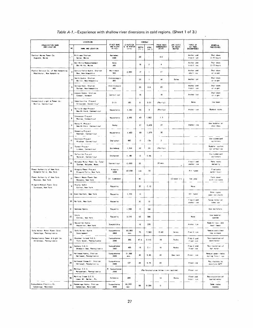
Table A-1.-Experience with shallow river diversions in cold regions. (Sheet 1 of 3.)
ORGANIZATIO'i NAN:: AND LOCATIO..
Central Maine Power Co.
Augusta, Moine
Pub I ic Serv1ce Co. of New Hampshire
Manchester, Ne1111 Hampshire
Con nee t i cut L i gh t & Power Co .
Berlin, Connecticut
Power Authority of Neflf Yo.rk
Niagara Falls, New York
Power Authority of New York
Massena, New York
Niogaro·Mohawk Power Corp
Syracuse, Nert York
Safe Harbor Water Power Corp.
Cones togo, Pennsy I van i a
Pennsylvania Power & Light Co.
Allentown, Pennsylvania
Susquehanna E I ec t r i c Co .
Conowingo, Mel ry I and
OIVERSIO'I
NO. ,_ ANO LOCATIO..
Wi II iams Staf ion
t 1
Solon, Moine
10
II
16
17
Bar Mi lis Redevelopment
Bar Mi lis, Moine
Gorvin Foils Hydra. Station
Bow, New Hompsh ire
Smith Hydro. s·tat ion
Berlin. NeYW Hampshire
Gorham Hydr. Station
Gar ham, New Hcnpsh ire
Canaan Hydro. Stat ion
Canaan. Vermont
Robertsville Project
Colebrook, Connecticut
Bulls Bridge Project
New Mi I ford, Connect 1cut
Stevenson ProJect
Monroe, Connecticut
Rocky R. ProJect
New M i I ford, Con nee t i cut
Shepol ig PrOJect
Newt own , Connect i cut
Niagara Power Project
Niagara Falls, New York
Robert Moses Power Dam Massena, New York
IS H1gley Hydro
Colton, New York
19 East Norfolk, New York
20 Ncrfolk, New York
21 Hannawa Hydro.
Stark 22
Colton, New York
Brunner Island S.E.S. 25
York Hoven, Pennsy l'w'an i a
26 Sunbury S.E.S.
28
Shamokin Dam, Pennsylvania
Holf,.ood St&OGl El. Station
HoI t "ood, Pennsy ~van i a
29 Montour S.E.S.
Watsontown, Pennsylvania
Martins Creek S.E.S.
LOIIII'er Mt. Bethel. Po.
31 Conowir'Milio Hydro. Station
Conow!090, Maryland
RIVER NAME ANO WIOTii
IN FEET
Kennebec
1000
Sa co
400
Merrimock
700
Androscoggin
300
Androscoggin
400
Connecticut
St iII
House tonic
Housctonic
Rocky
House ton it.:
Shetucket
Quinebaug
Shetucket
Con nee t i cut
Niagara
5000
St. Lawrence
RoQuet te
Ra'!uette
Raquette
Roquet te
Raquette
Oswego t chi e
Susquehanna
4869
Susquehanna
2000
Susquehanna
2500
Susquehanna
2800
SusQuehanna
2800
W. Susquehanna
2500
Delewore
Susquehanna
4000
FOREBAY
0 IVERS I 0.. f------r---1 TRASH RACK Q I N W INTER OEPTii AREA SLIBIERGENCE
( c(s) ( t t. ) ( cc. ) IN FT.
20 4-5
15
2,650 12 17
20 18
20 0.6 20
18 18
100 0.01 (Partly)
I ,250 25 (Part ry)
2,800 40 1,063 I .5
57 5,600 27
2.500 90 1,870 30
900 17 134
1,300 22 29 (Pertly)
1,100 12 0.05
10,000 33 33 mcx.
87,000 110 70
80
20 0. 10
I, 770 14
20 10
1,500 15 168
3,010 53 586
16 239
65,000 75 7,360 15-63
900 47.5 0.173 18
465 18 0.1 IS
31,500 40 5.65 40
127 20 5. 75 20
ARE GATES OR RACKS HEATED
Gctes
(Closed in)
Gates
Rocks
Racks
One rock
(Perforated pipe beiCM river bottom)
265 14 Racks
85,000 98 9,000
27
TYPES OF ICE PBMS
ENIXU'ITERED
Anchor and
frazi I ice
Anchor and
trozi I ice
Ar.chor and
shell ice
Anchor ice
Anchor and
frazi I ice
Anchor ice
None
Anchor ice
Anchor ice
Fraz i I and
anchor ice
All types
Ice jams
None
All types
Frozi I and
anchor 1ce
None
Anchor ice
Frazi I
Fraz 1 I and
f loot 1 ce
Fraz i I and
float ice
Froz i I
Float
Float
Float and frozi I ice
REMEDIAL PROCEDURES
Shut down
2-10 hours
Shut down
2-10 hours
Shut down
at night
Shut down
at night
Shut down
at night
Shut down
at night
Ice boom
Remove rocks
Use bubbler or
shut down
Use submerged
agi to tors
Bubbler system
not effect1ve
Use submerged
ogi toters
Rake rocks
oonua I I y
Fluctuate
water level
Form cover
with ice boom
Rake rocks
open ice chute
Surge water or
rake ice
Use 091 toters
Use bubbler
system
Bubbler sys. and
heat lamps
Remove ond c I eon
top screens
Recirculation of ,.arm water
Recirculation of
hot water
Remove upper racks
during froz1l run
Recirculate to
maintain 38°F
Rec1 rculat ion of
heoted water
Some rocks
wooden
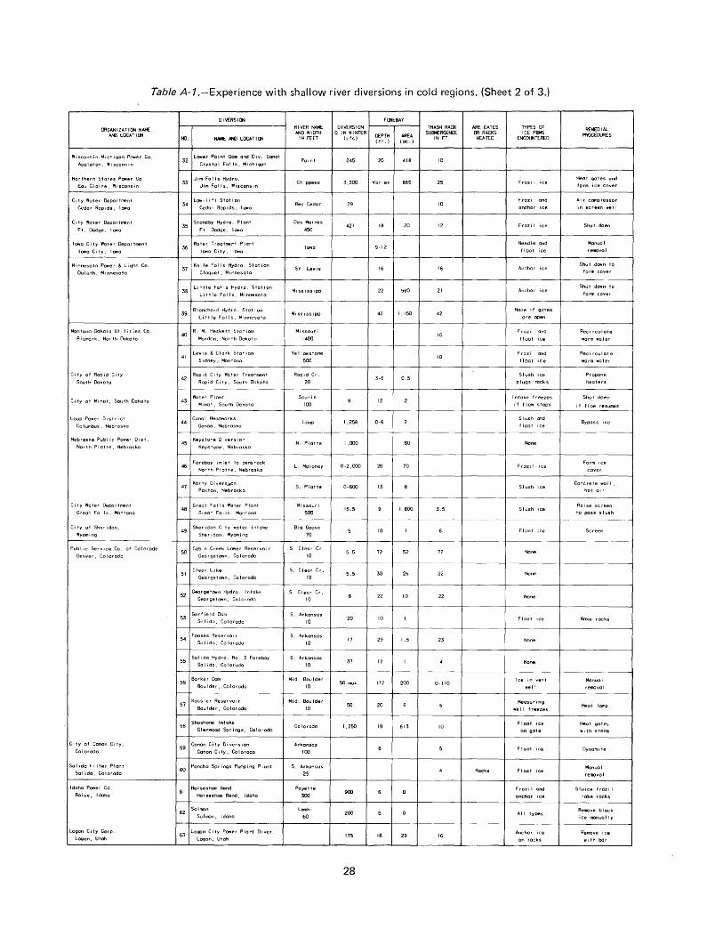
Table A-1.-Experience with shallow river diversions in cold regions. (Sheet 2 of 3.)
CllGANIZATION NAI-£ Al-l) LOCAT 10'4
Wisconsin-Michigan Po..er Co.
Appl~ton, Wisconsin
Northern States Power Co.
Eou Claire, Wiscons~n
City Water Deportment
Cedar Rapids, IO¥ta
City Water Deportment
Ft. Dodge, l<l¥'a
Iowa City "oter Deportment
Iowa City, Iowa
Minnesota Power & Light Co.
Duluth. Minnesota
Montono-Ookota Ut • I it ies Co.
Bismark, North Dakota
City of Rapid C1ty
South Dakota
City of Minot, South Dakota
Loup Power O,strict
Columbus, Nebraska
Nebraska Pub I ic Power Dist.
North Platte, Nebraska
City Water Department
Great Fa 11 s, Montano
City of Sheridan,
Wyomi n9
Pub I ic Serv•ce Co. of Cotorado
Denver, Colorado
City of Canon City,
Colorado
Sal ide Fi Iter Plant
Sot ida, Colorado
Idaho P~er Co
Boise, Idaho
Logon City Corp
LOgon, Utatl
DIVERSION
r«l. - /IKJ LOC~TIO'l
32 L09'rer Point Dam and Oiv. Canol
Crystal Falls, Michigan
34 L~-lift Station
Cedo r Rapids , I owe
39 Blanchard Hydro. Station
Little Falls, Minnesota
40 R. H. Heskett Station
Mordon, North Dakota
41 Lewis & Clark Station
S 1dney ,·, Montana
42 Rapid City Water Treatment
Rapid City, South Dakota
Water Plant 43
Minot. South Dakota
Cona I Headworks 44
Genoa, Nebraska
45 Keystone Diversion
Keystone, Nebraska
48 Great Falls Water Plant
Great Falls, Montano
49 Sheridan City water intake
Sher•don, Wyoming
51 Clear Lake
Georget~n. Colorado
Sol ida, Colorado
Fooses Reserve• r 54
56 Berke r Dam
Boulder, Colorado
57 Kassler Reservoir
Boulder, Colorado
58 Shoshone Intake
Glenwood Springs, Colorado
59 Canon City 0 i version
Canon City, Colorado
60 Poncho Springs Pumping Plant
Horseshoe Bend 61
Horseshoe Bend. Idaho
Salmon 62
Salmon, Idaho
63 Logon City Power Plant Diver.
Logon, Utah
RIVER NAME AND WIDTH
IN FEET
Point
Chi ppewo
Red Cedar
Des Moines
450
Iowa
St. Lewis
Mi 55 issippi
H1 ssissippl
Missouri
1400
Ye 11owstone
500
Rapid Cr _
20
Souris
100
Loup
N. Platte
L. Ma Ioney
S. Platte
Hissour i
500
Big Goose
70
S Clear Cr
10
S. Clear Cr.
10
S. Clear Cr.
ID
S _ Arkansas
10
S Ar~onsas
10
S. Arkansas
10
Hid. Boulder
10
Mid. Boulder
10
Colorado
Arkonso.s
100
S. Arkansas
25
Po yet te
300
Lemhi
60
DIVERSION Q IN WINTER
(cis)
245
3,300
29
421
I ,258
1,000
0-2,000
0-600
15.5
5.5
5.5
20
17
37
50 max.
50
1,250
900
200
175
28
FORE BAY
DEPTH (ft.)
20
AREA (oc. >
418
Varies 865
18 20
5-12
16
22 580
42 1,150
3-6 0.5
12
0-6
160
20 70
13
1,800
10
72 52
3D 26
22 10
ID
29 1.5
17
177 200
20
19 613
16 29
TRASH RACK SUHRGENCE
IN FT.
10
25
10
12
16
21
42
10
10
3.5
72
22
22
23
0-110
10
16
ARE GATES Ill RACKS
HEATED
Rocks
TYPES OF ICE PBMS
ENCO!J;TERED
Frozi I ice
Frozi I and
anchor ice
Frozi I ice
Needle and
float ice
Anchor ice
Anchor ice
None 1 f gcrtes
ore open
Fraz i 1 and
float •ce
Frozi I and
f loot 1ce
Slush ice
plugs rocks
Intake freezes
if flow stops
Slush end
f loot ice
None
Froz1 I ice
Slush ice
Slush ice
Float ice
None
None
None
Float ice
None
None
Ice in vent
well
Meosur i ng
well freezes
Ftoat ice
on 90te
Float
Float
Frozi I and
anchor ice
All types
Anchor ice
on rocks
REMEDIAL PROCEDURES
Heot gates and
form ice cover
Air compressor
in screen well
Shut down
Manual
removal
Shut down to
form cover
Shut dOwn to
form cover
Reci rculote
worm water
Recirculate
worm water
Propane
heaters
Shut down
if fiOf'l r'E!SUITM!!S
Bypass ice
Form 1ce
Concrete wall,
hot a1 r
Raise sc .reen
to pass s I ush
Screen
Rake rockS
Monuol
removo I
Heat lomp
Heat gates
w1 th steam
Dynomi te
Manual
reroovol
Sl"uice frozi I
rake racks
Remove block
ice manually
Remove •ce
with bar
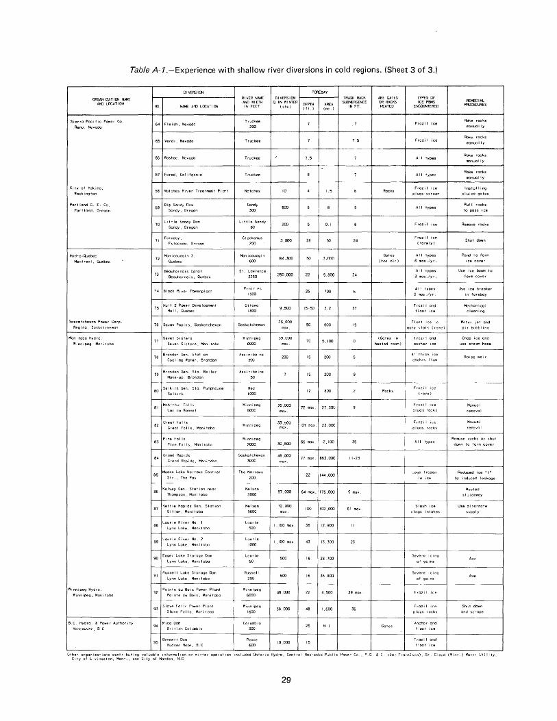
Table A-1.-Experience with shallow river diversions in cold regions. (Sheet 3 of 3.)
ORGANIZATION NN-1£ AND LOCA T I ON
!:!ierro Pacific Power Co
Reno, Nevada
City of Yakima,
Washington
Port land G. E. Co.
Port I and, Oregon
Hydro·Quebec
Mont reo I, Quebec
Saskatchewan Power Corp.
Reg i no, Saskatchewan
Man i tobo Hydro
Winnipeg, Moni tobo
Winnipeg Hydro.
Winnipeg, Manitoba
B.C. Hydro. & Power Authority
Vancouver, B. C
DIVERSION
i'tJ NAME AND LOCAT I ON
64 Fleish. Nevada
65 Verd 1, Nevada
56 Washoe, Nevada
67 Farad, Cali forn1o
68 Notches R1ver Treatment Plant
69 Big Sandy Dam
Sandy, 0 regan
10 Little Sandy Dam
Sandy, Oregon
71 Fa~:~:~~do, Oregon
72 Man i couag in 3,
Quebec
73 Beauharnois Canol
Beouho r no i s , Quebec
74 Block River Powerplont
76 Souaw Rap ids, Saskatchewan
77 Seven St sters
Seven S t s ters, Man i tobo
78 Brandon Gen. Station
Coo I i ng Water, Brandon
79 Brandon Gen. Sta. Boiler
Make ·UP, Brandon
80 Se~:;:~r~en. Sta. Pumphouse
81 McArthur Falls
Lac du Bonnet
82 Great Falls
Great Falls, Manitoba
Pine Fol Is 83
Pine Fa I I s , Man i t oba
64 Grand Rapids
Grand Rapids, Man i tobo
86 Kelsey Gen. Stat ion near
Thompson. Man i tobo
87 Kettle Rap1ds Gen. Stot•on
Gi I lam, Mont tobo
68 Lourie River No. I
Lynn Lake, Mont tobo
Laurie River No. 2 89
Lynn Lake, Manitoba
90 Eager Lake Storage Dam
Lynn Lake, Man i tobo
91 Russet I Lake Storage Dan
Lynn Lake, Manitoba
93 Slave Fotls Power Plant
Slave Falls, ~vnitobo
94 Mica Dam
British Columbia
RIVER NAto£ MlJ WI 01H IN FEET
Truckee
200
Tru:kee
Truckee
Truckee
Notches
Sardy
300
Little Sandy
80
C I ockomus
250
Men i couog t n
600
S t . Low renee
3250
Prot r tes
1500
OttOn'O 1800
Soska t chewan
Winnipeg
8000
Ass i n i bo i ne
300
Assiniboine
150
Red
lOOO
Winnipeg
5000
Yiinnipeg
Wt nnt peg
2000
Saskatchewan
3000
The Norr~s
200
Nelson
3000
Nelson
5600
Lourie
500
Lourie
1000
Laurie
50
Russell
zoo
Winnipeg
1600
Columbia
300
Peace
600
01 VERSION Q IN WINTER
(cis)
10
600
200
3,000
84.300
250.000
9,500
35,000
39,000
200
35,000
33.500
30,500
48.000
FOREBAY
DEPTH (ft.)
7.5
28
50
22
25
AREA (oc.)
1.5
0.1
50
3,000
5.800
700
15-50 3.2
50 600
70 5,100
15 200
15 200
12 800
72 max. 27,300
107 max. 23,000
55 max. 2,100
77- max. 863,000
22 144,000
57,000 64 max. 175,000
72,000 100 102,000
1,100 max. 35 12.900
I ,100 max. 43 13,300
500 16 28,700
600 16 35,800
46.000 22 4,500
38,000 48 I ,600
25 Ni I
10,000 15
TRASH RACK SUBfoERGENCE
IN FT.
7. 5
24
24
37
15
35
11-23
9 max.
51 max
II
23
39 mox.
36
ARE GATES OR RACKS HEATED
Rocks
Gates
(hot oi r)
(Gates in
heated room)
Rocks
Gates
TYPES OF ICE PSMS
ENCCUITERED
Frozi I ice
Frozi I ice
All types
All types
Fraz i I ice
pi ugs screen
All types
Fraz i I
Froz i I
(rarely)
All types
6 mas ,/y r,
All types
3 mas ./yr.
All types
3 mas ./yr.
Frazi I and
f loot tee
Float ice in
gate slots (rare)
Frozi I and
anchor tee
4' thick ice
chokes flow
Frozi I ice
(rare)
Frazi I tee
pi ugs rocks
Fr-azi I ice
pI ugs rocks
All types
Logs frozen
Slush tee
clogs intakes
Severe icing
of goins
Severe icing
of gains
Frazi I ice
Frazi I
pI ugs rocks
Anchor and
f loot 1ce
Fraz i l and
f loot ice
REfoEDIAL PROCEDURES
Rake rocks
manually
Rake racks
manually
Rake racks
manually
Rake rocks
manually
Installing
sluice gates
Pull rocks
to pass ice
Remove rocks
Shut down
Pond to form
Use ice boom to
form cover
Use ice breoke r
in forebay
Me chon I COl
c leon i ng
Water jet and
oi r bubbling
Chop ice and
use steam hose
Ro i se weir
Manu a I
r-emove I
Monuol
removal
Remove rocks or shut
down to form cover
Reduced ice "t" by 1 nduced I eokage
Heated
sluiceway
Use ol ternote
supply
Axe
Shut down
and scrape
Other organizations contr1buting valuable mforrnatton on wtnter- operatton included Ontor10 Hydro, Central Nebraska Public Power Co, P.G. & E {Son Francisco), St Cloud (M,nn.} 'rioter Utility, C•ty of Livingston, Mont., and C1ty of Mandan, N.D
29
the river flows northward; that is, if the headwaters could be melting and flowing while the river proper is still ice covered. During cover formation, problems may be caused by frazil generation in the supercooled open water reaches, or by a heavy snow, or by onshore winds of 20 miles per hour (32 km/h) or greater. A blizzard during ice-cover formation is the worst possible situation. In some plants, water is diverted to the spillway to reduce the approach velocity to the generating station and encourage formation of an ice cover.
(b) Ice-free river.-lf the formation of an ice cover is not feasible, Ontario Hydro uses the following procedures:
( 1) Provide a straining device to separate floating ice from diverted water.
(2) Locate the strainer where there will be a downriver velocity at all times. Such velocity must be 1 .0 ft/s (0.3 m/s) or greater, or the surface flow will tend to stop during onshore or upriver winds, or if the air temperature is below 10° F (minus 12° C).
(3) Design the strainer so the water diverted per foot of intake length is uniform, with no vortices or local high velocity areas; The intake velocity may be higher than the river velocity by a factor of four or five.
(4) Provide adequate vertical height to the strainer so that it wi II work equally well with the extremes of water level.
Notwithstanding the above procedures, Ontario Hydro experiences a heavy flow of frazil ice into the intakes and through the generating station when the top two trashrack sections are removed to prevent blockage. The headgates are all installed in enclosed and heated areas. Cooling water for the generators formerly was taken from the penstocks, but this proved unreliable during frazil runs. Therefore, a pump from the draft tube was installed to provide a reliable source of cooling water to the generator.
(c) Shallow river diversions.-Ontario Hydro has five plants which divert water from areas of about 15 feet (4.6 m) in depth. They have generally been unsatisfactory under some weather conditions, requiring the following procedures:
30
( 1) Heat is provided to deactivate the frazi I ice and ensure that the racks, traveling screens, and strainers do not become plugged.
(2) Heat is added at the point of diversion from the river to ensure mixing and in sufficient quantity to obtain about 2° F ( 1° C) temperature rise.
(3) Consideration is given to covering the intake channel if it is more than 100 yards (92 m) in length.
(d) Miscellaneous considerations.-Ontario Hydro concludes with the following suggestions:
Sluiceways which are most satisfactory are of the overfall type. Where gates are used the gate guides and the gates proper should be heated. Problems occur if the gate seals leak, or if there is considerable splashing during subfreezing temperatures.
Ontario Hydro's worst problems are caused by heavy snow and wind over open water areas when the water is supercooled. The frazil ice problem was sufficient to warrant investigation of this phenomenon as an International Hydrologic Decade project.
5. Niagara MohP·!Vk Power Corporation.-A constant water level is maintained on the 12 diversion forebays to freeze an ice cover as early as possible in the fall. Most have provisions for sluicing ice from the fore bay, and when a large accumulation of floe ice occurs, the plant is shut down for about 10 minutes to float the ice over the dam or sluiceway.
Some plants are equipped with bubbler systems or agitators in front of the gates to prevent freezing of the gates and to ensure operability. Some gates also have heat lamps placed in the corners of the gates.
6. Manitoba Hydro.-Manitoba Hydro reports that ice problems are negligible at many of their 15 diversion facilities. However, a variety of problems occurring at other plants are as follows:
(a) One diversion which has no submergence on the trashracks relies on heating the covered gate bay and pumphouse and sometimes the removal of ice with a clamshell.
(b) One shallow intake channel was almost choked when 4-foot-thick ( 1.2-m) surface ice was
formed. The rock weir was raised 3 feet (0.9 m) to provide a deeper channel.
(c) One diversion problem results from frazil ice which flows from an uncovered reach to flow under the ice cover on the forebay, attaining a thickness of 8 feet (2.4 m).
(d) Removal of spi II way stop logs is very difficult when a 4-foot ( 1 .2-m) thickness of ice forms on the logs. The ice thickness has been limited to 6 inches ( 15 em) by using a half-inch ( 1.3-cm) shim below the bottom logs to induce leakage.
(e) One facility has a problem with spray which freezes to form an ice bridge over the nappe of the spillway. This structure is in an area that is completely inaccessible for 12 weeks during the winter, and is accessible only by air the remainder of the year. No electrical power is available to the site.
1. Safe Harbor Hydroelectric Development.-The Safe Harbor Hydroelectric Development on the Susquehanna River has for many years been a virtual laboratory for research in the field of ice problems related to winter operation of the hydroelectric plant where Granbois [5] pioneered the science of accurate prediction of frazil ice formation. While the immensity of the plant removes it from the category of diversion facilities to which this report is directed, some of the ice problems encountered there are typical and should be noted.
Air bubblers have been effective in preventing the formation of surface ice against the spillway gates, but when extended 2,000 feet (61 0 m) upstream, they are not effective in reducing the problem caused by heavy ice floes. It is advantageous to maintain a higher pond level when the heavy ice floe enters the pond. Opening of gates in excess of flow requirements lowers the pond elevation and will cause jams in the upstream area of the pond.
The forebay area is protected from ice by a skimmer wall which is ideally oriented, parallel to the riverbank. The spillway gates can be opened in a matter of minutes when an ice jam break occurs. Remote river stage recorders are located 5, 10, and 15 miles (8, 16, and 24 km) upstream from the dam to provide a warning that an ice jam break is imminent. Weather and flow conditions are transmitted to the Safe Harbor control room where records are maintained (fig. A-3).
*This sometimes requires shutting down temporarily.
31
All spillway and regulating gates are equipped with electric gate seal heaters to prevent freezing. Frazil ice runs are predicted by using a very sensitive water temperature recorder to determine the rate of cooling [5) (see sec. 81), and the top two units of trashracks are removed from each intake bay. Two oil-fired boilers are fired during an ice run to provide steam for cleaning ice from the pulled racks and for heating the hollow stay vanes of the turbine.
8. Denver Water Board.-The city of Denver wa te rsh e d collection system includes many high-altitude diversions on small streams. The Moffat Water Collection System in the vicinity of Fraser, Colorado, includes about 10 diversions at elevations ranging from 9200 to . 9500 feet. A 40-mlle long (64-km) conveyance system includes several tunnels and siphons, and many miles of canal, much of which has been covered with precast concrete units to protect the canal from snow, debris, and cold air.
The diversion structures are of simple design and are relatively problem free. The diverted flow varies from a minimum of 12 ft3 /s (0.34 m3 /s) in the winter to a maximum of 600 ft 3 /s ( 17 m 3 /s) in the spring.
9. Conclus.ions.-Of the 18 public and private diversion facilities having a forebay depth of 10 feet (3 m) or less, 17 have ice problems of some kind. The other diversion is oriented ideally with the river, having its intake flow alined normal to the streamflow, and having an ice boom in line with the riverbank to exclude river ice from the fore bay.
While a deep forebay does not assure trouble-free operation, good trashrack submergence, in conjunction with provisions for forming an ice cover and for sluicing out excess river ice, together with provisions for heating trashracks and gates, should assure year-round operation with a minimum of ice-related problems.·
The various procedures used to combat ice problems include (see table A-1):
(a) Formation of an ice cover as early as practicable.*
(b) Use of a bubbler system to keep the trash racks ice free.
(c) L:Jse of an ice boom to exclude excess surface ice from the forebay area.
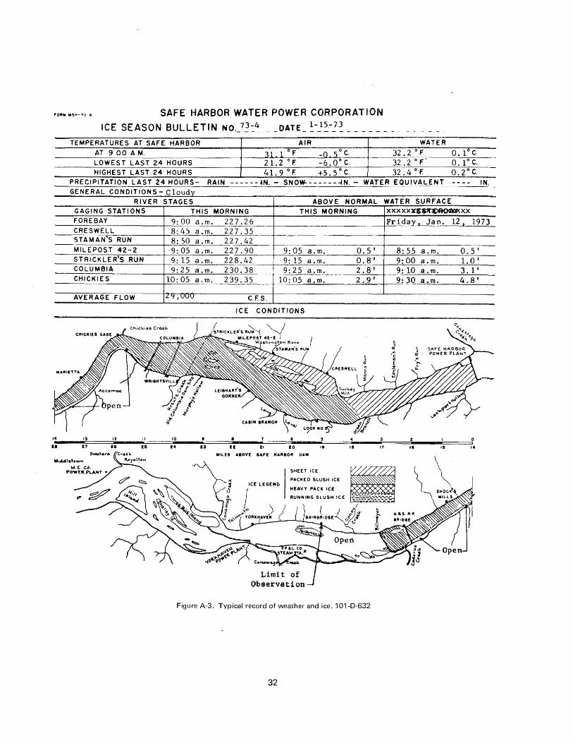
SAFE HARBOR WATER POWER CORPORATION
ICE SEASON BULLETIN No._7~-::_4 ___ DATE_ ~--1~-!~ _________ _ TEMPERATURES AT SAFE HARBOR AIR WATER
AT 9 00 A.M. 31 1 ° F. -0 50 c. 32.2 ° F 0. 1° C.
LOWEST LAST 24 HOURS 21.2 °F -6.0° c. 32.2 ° F.' 0. 1 o C.
HIGHEST LAST 24 HOURS 41.9°F. +5. 5° c. 32. 4 ° F. 0. 2° C. PRECIPITATION LAST 24 HOURS- RAIN ------ .. N.- SNOW--------IN.- WATER EQUIVALENT ---- IN.
GENERAL CONDITIONS Cl d - ou ty RIVER STAGES
GAGING STATIONS THIS FORE BAY 9:00 a.m. CRESWELL 8:45 a.m. STAMAN'S RUN 8:50 a.m. MILEPOST 42-2 9:05 a.m. STRICKLER'S RUN 9: 15 a.m. COLUMBIA 9:25 a.m. CHICKIES 10:05 a.m.
AVERAGE FLOW IL'::I ,uuu
ABOVE NORMAL
MORNING THIS MORNING
22 7. 2 6 227.35 22 7. 42 227.90 9:05 a.m. 228.42 9: 15 a.m. 230.38 9:25 a.m. 239.35 10:05 a.m.
C. F. S.
ICE CONDITIONS
IIILfS AIOV! IAFf HARBOR DAI\II
SHEET ICE
PACKEO SLUSH ICE
HEAVY PACK ICE
Observation
0.5 I
0.8 1
2.8 1
2. 9 I
Figure A-3. Typical record of weather and ice. 101-D-632
32
WATER SURFACE xxxxxu~xx
Friday l._ Jan. 12) 1973
8:55 a.m. 0.5 1
9:00 a.m. 1.0 I
9:10 a.m. 3. 1 I 9:30 a.m. 4.8 1
II IS 14
(d) Removal or ra1smg of trashracks to pass ice through the system.**
(e) Removal of ice from the forebay area by sluicing over a spillway or ice sluice.
(f) Covering trashracks or gates to mm1m1ze cooling and to preclude formation of frazil ice in the area so covered.
(g) Heating of trashracks or gates by use of electric current, propane heaters, heat lamps, hot air, steam hose, or flame thrower.
(h) Cleaning of trashracks.*
(i) Manual removal of ice from the fore bay.
(j) Use of agitators to prevent a buildup of ice on the trashracks.
(k) Recirculating warm water through the intake.
(I) Use of dynamite to aid in removal of ice.
**This is permissible if frazil ice is inactive (see sec. 81 ), and if floe ice is in pieces smaller than the turbine openings.
*This sometimes requires shutting down temporarily.
33
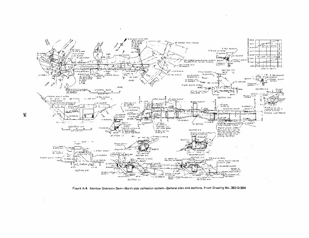
~
.... .. -.,., ~~
••• ,o.
.. / :/
I c"4:'4;! o~r;;.';_t,o~~a ~ to,o,., P.C.2+4!f,JB - --;-- ....... t- ........., . i::::_
o pr.z~74.oo ...... -!"::.Jy·C lvanhoo c~_. <~"''' ~ ~ r.ii:J ~:14,0.90:: ~ ., • f :~ ~ lti,UII :5 ilfN~f di)t:ll<
\ L-28.621(. 4: •....,... 2~P,p• Jumd,_il ~ IO,oot .
..Y "E ~ • •\- ·.,. .J.... .' s·c,-ooud .,..,1:.2cu'9- t. JD,DD7' ~ r I I :\\!).. /~' ·-....._,....._,-.. ~ EltO,ON.B-i'\-:-'2 " ~
~ ' , ... - £lt0,01$..Z1" ~ JO,QO.!J ..__ -
;,._-- ~ .... • f !\:: I Tod ~k~ rrrl"'; curv• lot
',\, ' ' --~Sta. ZtM001VOI'Jh-.0w'".5tan Cond~n'f .. &d.fl"fl. ~ Or"ll)ln"'l 9ro.md ~IO,OO.l ~ ($}<--- ' ,' ~ '"'"'' -- -~ -- ··-1 ~ ~ ___ ·-';··~· _~:qJ __ ~-~> ·.;-: ... : ---;~'it.:'\, ~~;a,;~;~~r •• ., c~,..... · · .s -'B'"~:i.·w ~ \ . --~ o49.oo·' 1-i,:t .. · - · ' ' ....
(l'.hnm.•;#r-- ~- -:/':::1 • .S9'tt:.'o:rw
2 :s 4 $
FLOW IN 100 CJ.:i
2" Pip<~~ l>ond~Y~H·-.......-
hl."-£1.10,0t.Z.? EI.IQ0/£25
Q•605t:f.l.- ~-- )_
tqo.zo
.10,050
J~o" -I •2' Pip:s~~~oil ~ ~ .• - "-" ' ~-NO< . ~-:\--~- c:;,•-·• ,- •"" . ~- ~ ;~ ' . ·-· _._ -~···· .. -: -J ~··•"·'" ~m~ •• .,_ ·- , . ." -· ... . • : - ·:-- ., • .,.., -~ -- ' ... :>.-'""
~<''." .. ,. .• _ • ' ·'' '",' ' - ' ' --•'< • . ' • - ' '" ·-.. •"""" ,__ . ' •I _z;c', ,, . ' . .· . .,;'" "~ ..... -- ... ~- ··-- u ---o't' ,. .------ "'-'~ "'"• c •.•• ' ... __ _. , . "- .. . ' r;:::;;,· ', :>.:;::.;;;·• " .
• ... - H '··"" .. .L, ~-- ' -- _,_. •• '
0
" • ' ' ., "~ . '. -1 TYPI~A:•d•utal
.......... ' '· " ""'"~ S•.Ofll4
..... c,·: t.lr: ~
.C'I. •IJ,(.)O.<J,,j
Zi'~o" --9~--
:JE.CTION 8·~
Figure A-4. Ivanhoe Diversion Dam-North side collection system-General plan and sections. From Drawing No. 382-D-884
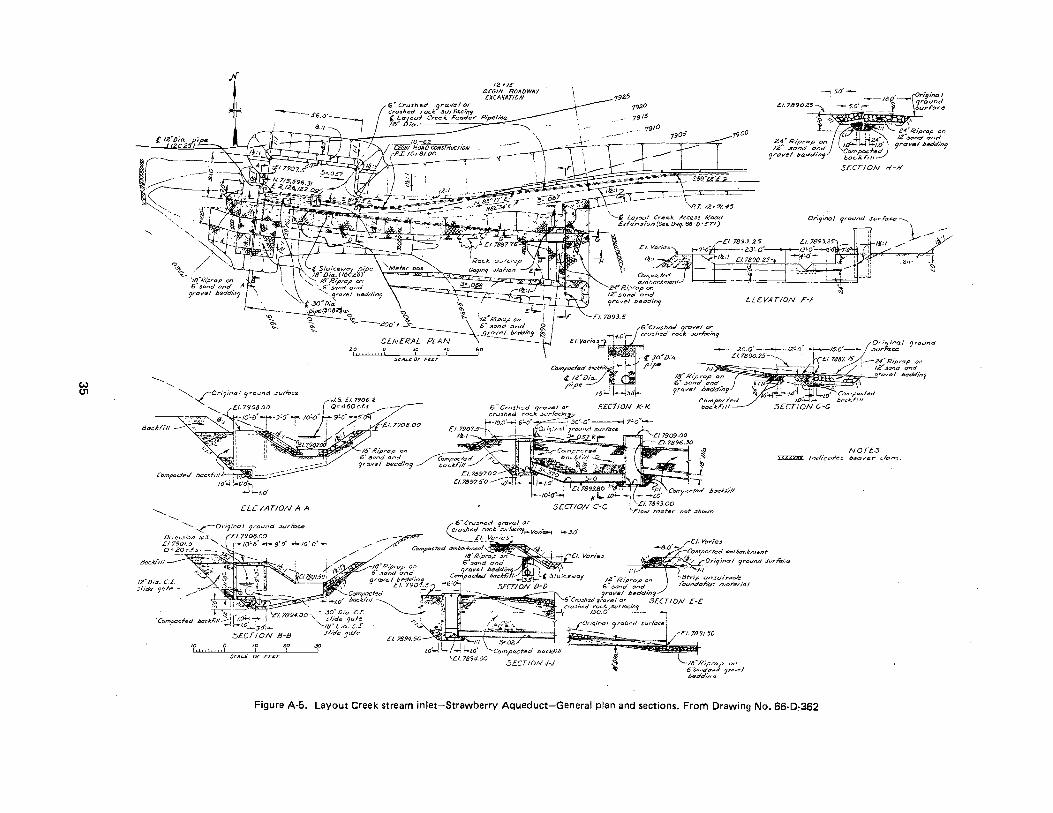
w U1
Jf
."'
"' ~\~
'----ELEVATION A-A
-------
JZ"Dia. C.I.
12 .,.IS BEGIN ROADWAY E.XCAVATION
l Layout Cree A:. Fesde.r Pipeline (
6 .. Crushe~ qra.velor cru:Jhed roc.J:. .:Jt.Jrfa..c.ln9
11roia.. :::::::---~
.CO 0 .20 40 GO
SCAI.£ OF l't:£r
--19Z5 7920 £1.7890.25~-
,:\)~<;.~~~ 'f
'(900
SECTION H-H
ELEVATION r-r
6'"Crushsd 9rr::1ve/ or cru::fhad roc.lc stJrf'acirJtj
--- 200'--t----12'0" ~Or"l'na.t grouncl €?o"D/o.. £1789025-· - -15.0--' .surFace ?'P(fl ~- D 7887. 75 -1:/ - -24 R1p•ap 0 ,,
IC( Rt:,Orap on - _ ' 12.N3and and
,.:J w"dl-;,.~~~d"~x,.,, ravs/ beddmy
6¥ Crush::?d qrcrvel or SEC7JON K·l<. crushed rack. .j .. u-Facin_p
r-to.o'-' 6co· -z::==:::_:__. 3o'-o" ----1 7'o"--Lt.J1~:::.....1'~ ! . ---~- -"' ·-·--' ----· _ _j - __ ,..___ ,
£~~ R;prap on sondand -~
9f'a.vel bedd/n'J ~;;;;;;:;:;;d A I:Joc.AI'i/1 __..-/ '-< .£/. 7.597.00
E!.7897.S'O ~--;,
":-3.0'
]!!~~~'{---£/. Vorie~ ~
NOTL-5 XXXXX:XX Jnd/co/-es aeaver .:lam.
sl,de 9afe -----::::::-.....-""" • 1 '-Compacted
-' t-,w' Daclt:n"tl ~.
m o m • • SC.AL£ 0/" r££T
SECTION J-J /~.'" Ripr~1:> on 6 .:;o,•do,..d 7r6...trl .beddl'no
Figure A-5. Layout Creek strearn inlet-Strawberry Aqueduct-General plan and sections. Frorn Drawing No. 66-0,362
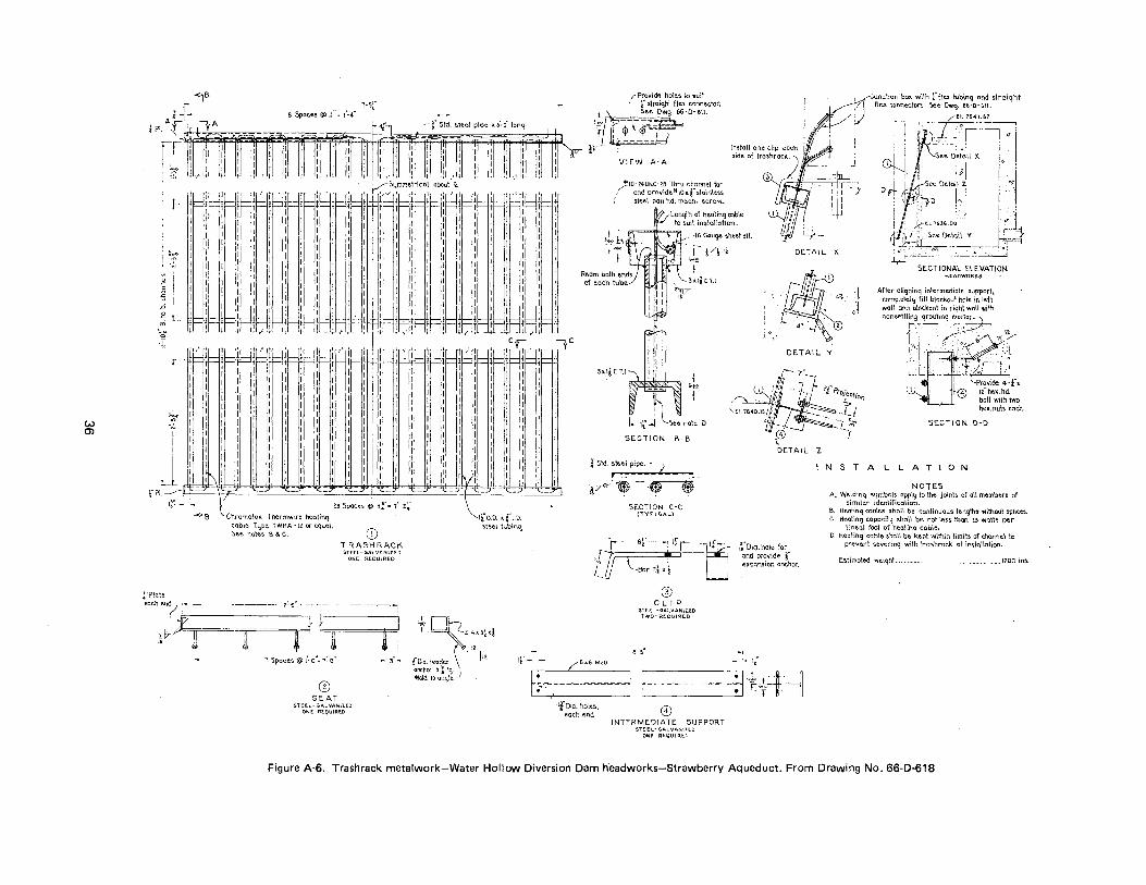
w 0)
-<lB
r · · · J~1 r-,- ..., · 'l rf t~" 'ifl 1W m fff ffi i*'l ffl' n. A.,...· v '"~· ~-~=m I rtfiff · · {PI~ ~t f.~---~ ~~ *?ftr ~~~s r: ~ · - I I d I
8 Spaces@> 11",. 1:...4 r:sr
~:z
-.:.
~ {i .0
: L
'~/' I I I
I I I I I I I I I I I I
:
~~~-1 :
I I I I i j '~ '
iH[w; I ~n, I I I I I I I I I I I I
I I I I I I
jr=l' I -I !
I I I
I i
I j t I j 1 1 T 1 I I I I 1 I I 1 I I I I I I
I I I I I I I I I I I
: I
l I 11 + - I I ! ~ V
I
VIEW A-A
~10-Z4UNC·ZB 'Jhru r.h.~mnel for ,- and orn..,ide'*IO;o;.l stainless
1 :;tee\ pan hd. mac\"\. screv.~.
.!
.,.~.,
r"j" ---16 Gauge sheet sH.
~- ijV~-Li •,.I~
!:
DETAIL X.
l ,l
--Junction bo:t. with r fle.x tubinq and straight flex conneclors. See Dwq. 66-0-611.
1 : -··ff,·.L-764_1_:~__,~ '-, - !-'' __ ,--_____... Q'
, .. - J I I I :.~ ~~i~il )\ 1: .
. I , I; . : D J ~ _,il Se< Detail~ : ··J.
: ' ''.,i}D !~_-.. ] ~-- ·., I '!1 '. . - .' :· l.. 'b I : J:El. '1636.00 : -~--
~ee Detail Y ___t;:··-~~ ; .:"'• . ~---~",;~ ~. "j -
SECTIONAL ELEVATION HEADWORKS
After a\iqninq intermediate support, complete!~;~ fill blackout hole in left waH and b\ockaut in riqh\ wall wi\h nome.ltl~~-.-qrou~~n: ___ ~~
:_2 --,c
!i I l,__fj>'ifflj>'[fif,' \ 1 'jly
:o .I)( i.·~·-·~-. •rfo, ~·,/\
[I'!' r 'ftR~I
~~
~! ,e---1 I ~~ th- IT~ 1 1 lf= IF 1 ~I ~~ .t::: j I~ 1
1 1 r: t 1 r ' 1 I I I I I I I I I I I I I I I I I I I I I I I I I I I I I I I I I I I I I 1 I I I I I I I I I 1 1 1 I I I I
~ I i I I I 1 I I I I I
II I I I I I I I I I I I I I I 1 I I I I I ·I I I 1 1 I I
' I I I I I I I I' I I I I I I l l I 1 1 I I I I I 1 I : : I I I 1 I 1 I I 1 I I I I 1 I I
L I 1\1 I 1 I I 1 I I I I I \i I I r· PI --------11.. ..... - .... ,.... _,_-" "\:: ,.. '\:- ..... :.._.:; Jj"" ~ _.z::
1r- :Ja 23 Spaces @ 3f"' r'- zf Chromalol'. Thermwire healmq ~able Type TWHA- 12 or equal. See nole~ B &. C.
. . \_,~ '" -\4 O.D. "'-4 l.O.
steel tubin~
.T:"Plate
CD TRASHRACK
STE.EL-GALVANlZ.lO ON~ REQU\ REO
-- ..i
eachend- ro-- --~--~~- 7~6"----- -- -----~
(4 ~~ il 3 {/-../- r( II ~ 1l1
• 1 Spaces @ 1'- o"~ r'- o" ..., 3"-
+~ L4-0~X~ " f"Dia. headed l12. If'- -
-,~ve-·
See note. D
SECTION B-B
SECTION C-C (TYPICAL)
DETAIL Y 1·-.··
·-7·1 1
.. / /" c[ProJeot;00 /]} ~
7_
-U -, ~ ... SECTION D-D --T
NSTALLATION
NOTES A. Weldinq symbols appli.j to the joints of all memben. of
similar idenliflcot\on. ~- Hea\inq cables shell be continuous lengths without splice$. c. HE".alinq copacih~ shall be not less. than z~ waits per
lineal foot of he.atinq cable.
·r- sr--. : lfr -'u . • I t. \_-Bar 2l x. -~ . and pro·-ilde r 1[j1r:-- -~-oia .. hole ror
· expansion anchor.
D. Healinq cable shall be kept within limib of channel to prevent severinq with \rashrock at installation.
Estimated weiqht -------------··---------------12:00 \bs.
/"6x.6 MZO
G) CLIP
STE.E.L· GAI..VANIZ.E.O TWO- RtQUIR£.0
a'-5"
tf
® SEAT
anchor 5 ~- lg. _ Weld to anqle) f;~:,~- --- .. --~-----~ .:~~--~----- -~~~:~H "f+~H
STE.E.L- GA!..VANllEO Ot>.lf. RtQIJlRE.O
-tfDia. holes, each end. 0
INTFRMEDIATE SUPPORT SlE.EI..- GALVAN\7EO
ONE RE.QU!RLL
Figure A-6. Trashrack metalwork-Water Hollow Diversion Dam headworks-Strawberry Aqueduct. From Drawing No. 66-D-618
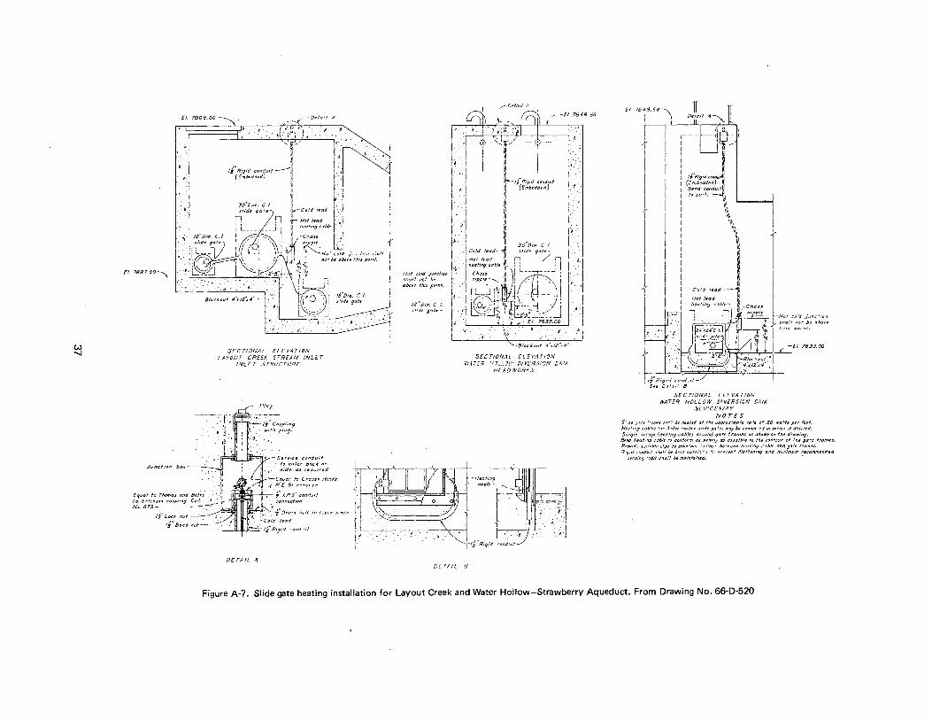
w -....!
£1. 79()8. 00
·•
Ct. 7897.00-,
J.Jncfion box-
- -.( -De fail A
t-711"'"~ ~1 ... 1.'"\ .. )· •. :
<ljl,,, ,,,
:1:
rJ"Rigid condyff -----~~~ ( =mhedded) 11/
30~/)ia. C./. slide gafe
'II
'" l' 1il t--cold lead
t- ~::f1~9a~ctb/e 11\ 1 -c;.,ase
.1'·
, ..
,....-Defat! A
-EI. 7649.50
i · ~- (,:;~~: ~v~ u'~f/' I i •
Ill ,II Ill II' 11~ ·f'"R ~~: :r( E-~~~d~:fl:rt 111
·o.·
~ .
111
II Ill
i' ,n
1· n~pple_ LL.
~1-fo.l old jo·o:fi;;,, .51all J; 110" De ubcve ffl,s po"·d.
Ill 111
Cold lead- ~I ~rDia. c_ 1_ Hot lead Ill 'de g<j<fe)
hea.~tng cable { 0 / n :~~ '' r n '0t (V :).
SECT!ONA:... ELEVATION LAYOUT CREEK STREAM INLET
INL£ T S T'?L'C TUHE
fF"!=iirr ~.0Serv1ce conduit · to r!nfer b!'I.Ck n,..
$ide us req.Jired.
. ~Eq1.1al to Cro:~S! Hinds · .f· R £51 re~iucer
~~- r I.PS' cond<.~l! connectirm
'-..:,~ f :Jrat? ,.;J/e tn c:ner a ,.~e
OETA!L A
Cl.
Hot cold J;ndi!'Jn sll~!l not he above litis pcmf.
t2"Di::r. C. I. sli:ie g':lfe-
Cb,, ~ L : ,1pple ill I --__,.,.-- -- _j _--......._111:(0·'' : r '- '~~- , -.. : ;: t I J ' -- \ ~~ r.J~c-· ,~ ) "-~11,--s·-.c-/j
1 1 ·· .- Ef-7635.oo ... SECTIONAL LL t:-V/1 TI?N
V1'.4;'""E:i' '··'J." ... J!·i' 0/Vl"R.:i!ON C.4:'A H£A!JWOR 1fS
cable ~_--L_H,al;:---
l' lt_--_=n"'"- _ _j
l -- - 1 l t· .1 ,___,____. --L.J
DE TAIL 8
..
-~ :
E!. 7649.50
+ 4of lead
-f;c-c"'-c-'or-'..-:j-~E/. 7633.00
SECTIONAL ELEVATION WAT.:T HOLI_OW D!V.ERSION D4M
SLUICEWAY NOTES
S' . .Je ].).'e "·Jmes su'.' b.- /'1ettletl af ff/e .Jopro.r.'mafe ,.ale o~ 20 wafts ptr foot. Ht::di"J :ab',.s r,,.. :1.1/er Lloflo:v .s/1de go'~J may he c'nnec.'~;J ir. seri~J tf desired. Single \Vrap heating cables ar.;und qate frames as shown Cl'l fhe drawiniJ.
Bend heat11:? cable to cor1:'or71 as 11errrfy as oD.s.sible to flu c:Jflfour af fhe gate fro.??es. Provd~ s~·.lr~bfe clips to m11tnfa1'1 ::n•uc! bt:'a·een ,~eafi.'l; C7b/e and gale frames. I'?':Jid c~nduif s.'>a/1 br be'lf car!',"'~-!~v •.- ore;'efl' t'.'at.'~.'lin9 and .n1nim11m recommenrie.:J
i>~11d:ng "'.td1i" sh:r.'l De mainfaintri. •
Figure A-7, Slide gate heating installation for Layout Creek and Water Hollow-Strawberry Aqueduct. From Drawing No. 66-D-520
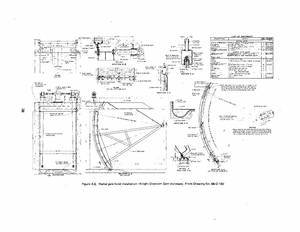
w ClO
~~ .. r{] I I I I
-·····[Orne 11111t
PLAN
,.Vl!ni1!41HJ!IfJ • CrtJU~·HIIIdss/11.
rcoi/I"PGtt•~
\ \ \
-~ :·0 :r ~·. I
1',
I• ••••• ·--H:::;;' ,::: ~:~~~~--- ··" .•
···IJ"Rigtd CfJIIdlllfiMIISIIIf .··1 httJfiiiQaJblt
}•· I·
{ ;\
ij, : 1". 1,.
,· ' I ··1 : ·~ I
81r• ro'lfr
SECTION 8·8 Grout poctet ,. .,.tJeri"detp·- ••
ffJSUif·····.
Jflllcf/011/lfJI· •• •
(qual fOfhOIIIfJS llld Btflf Co.(fi0SOII rfJUf)IIIIQCIJfNo679--.
""PIUf
.·--Cor~r '-i!"tdlluf_ "··ti"R•g•dCfJIIdUif
SECTION D-D
·.;"] :~~;;; s•lltollistrtllfht ~c:' -----·"'f.'.: . .,.f•18"Anchorbolts llldJttlrrll '•-Grollfll/lthft4' --~~~\\
: . ~' '"*•Ji"dte(l
PLAN GolrE Sll.t AND ~~CHO/f IDVS
17'-ff
tJ"Rtfld colldu•t-f. •• ~: -.\
!'..:.--·ll SECTION F-F
-~ -~
·Htlllttld htQIIIIfJtfl/1/e
-·--r"·"
'. . •• .. ,rR•t•d co11du•t
SECTION E-E
GrfiUt fl(Jc•rt tt" •· w•dr•Jfdrrp. .. •'
(·l"•e"Andorllatts
DETAIL C SECTION C-C
' ~ ~
:
;;
·~ '2 . ·-
L 1ST OF EQUIPMENT
J'Sttm,•7'-J"ifJII9 •"Wtdl!o.ffluct.9"-5"tollg.}"chtlmfrron0llltdgr
l1;.s: Moth bOt~.l ,.Uts, J.~ thrrtJd •18 Much llfJ/t,2n11fs.J thrud
•f•~"lluch llfJffw•thnuf I ••I Milch /loll w•th nut
ICE PREVENTION t(q.~~_.so!prifJntw•tllcoupllnis flft,tJpprtJ•Ienglh •,4 CfJ
"':IJ•o.\'1/'.lil'.':l
•• --·---Norc· Wollptutes ffJ lit str11•9hf 1111d set nllrmfJI til s111 • lllld[llfP•II/Ieurmgs.WtJIItJ!utistollrl•fhffJgomsf
!::~ '::o::',!:!'::;,o:~ ~! !~,{:'~~~t:J~ tl:.t~":r '::;/ut
·-...,~a·.f' 1" r o,
H-o,,/Jt",.t!'
tj"riO"AIIcharlttllts-
'>
NOr£ [ 8rtwttfl btGflllgS lalltsetlerrtodd /JfJt~llrltagotts•ll.·
_r. ~ ···-,1.
'ii" . .J•~ -. . ,. prOI
(
NOTES
~ '-:"'·'i _,.7' .....
HtCJtmgcobltfor .. "llfJIDIISt111dgotrs•llsholthare,~at~tg t:"Ptx:•tr of tJ{J(VYJ~ 20 """s per fMI ,,h IIOFfQ/1 powrr SUIJI)Iy
Rlf•d tfJIIdutf sbo/1 lit /ltdf cturfullr taoro1d fltltten•nf. lrlm rrcammt11drd /llddlllg rod11 shall/It "'"'"'''"'d
\ ... \
"" "'
SECTION A-A II'~LL PtiiTE ~/liD ~~CHO" BOtTS
>
Figure A·S. Radial gate hoist installation-Knight Diversion Dam sluiceway. From Drawing No. 66-D-180
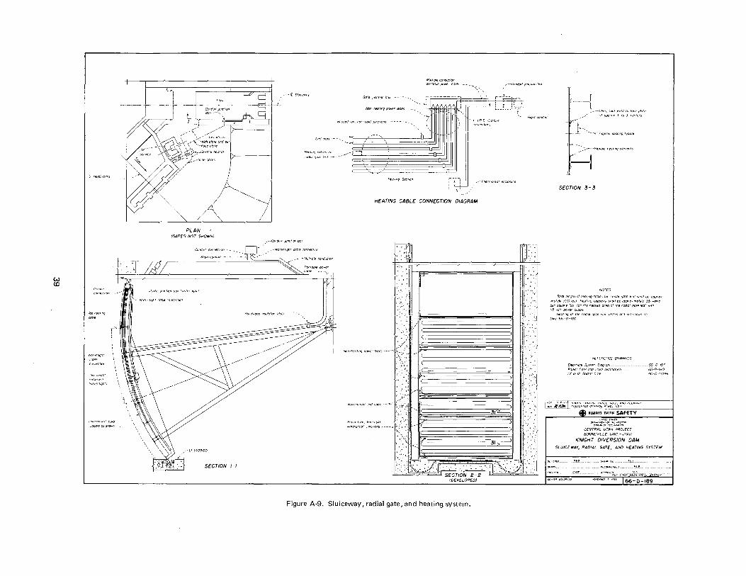
w co
fi Headwork>
roo healmq
Wotert,qht cable
enclosure lwatert•qhtl
r'"
' ' ' ' ' \
PLAN (GAT[S-NOT SHOWN)
~ ~·
I
,--1[ Slurcewoy
L
•. CondUtt ;uru;tl()n box
Gate JunctrOn box
Non · hec lrnq power
Brazed-on. /lot-cold Junctrons --
Hear.nq Sect,;n
Mu/t,p!e corductor per/able power cable
HEATING CABLE CONNECTION DIAGRAM
[]
ilion-hf!Oirnq oower leads
waterproof encJcoos
~--' .
_---Con~J<,it tunct.on t>o<
~..'!--,
([ . .
-3F---- ·--··.
__)
Bc,ed oc. "''."" r· ' ' w<Jierprool ;unct.ans ----~ .• •·.•.·•.· .•..•. -.· ••. •.·.· •• ·.• ..•.•.••... · ••. -•.•.. ··•••·.·· •• :tsi .......... w
SECTION 2-2 rDEVELOPED)
Figure A-9. Sluiceway, radial gate, and heating system.
lock weld to lace alate
ooprox !"to J" centers
neat•nqerements
SECTION 3-3
Tala/ lenqlh of heoMq cables Ia• ,-a(j,QI qote teal slloll be aoorox
,molely 350 teet Heat•nq coooc.ry 5/10/1 be oopra .. molely 35 walls oer souore foot lor the heated area of 115 volt power supply
Heat.nq of the rod•OI qote wail plates and sdl shown on Dwr; 66-D-180
REF[R[NC[ DRAWINGS
CENTRAL UTAH PROJECT BONNEVILLE UNIT-UTAH
KNIGHT 0/VERSION DAM SLUICEWAY, RADIAL GATE, AND HEATING SYSTEM

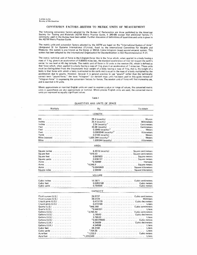
7-1750 (3-71) Bureau of Reclamation
CONVERSION FACTORS-BRITISH TO METRIC UNITS OF MEASUREMENT
The following conversion factors adopted by the Bureau of Reclamation are those published by the American Society for Testing and Materials (ASTM Metric Practice Guide, E 380-68) except that additional factors (*) commonly used in the Bureau have been added. Further discussion of definitions of quantities and units is given in the ASTM Metric Practice Guide.
The metric units and conversion factors adopted by the ASTM are based on the "International System of Units" (designated Sl for Systeme International d'Unites), fixed by the International Committee for Weights and Measures; this system is also known as the Giorgi or MKSA (meter-kilogram (mass)-second-ampere) system. This system has been adopted by the International Organization for Standardization in ISO Recommendation R-31.
The metric technical unit of force is the kilogram-force; this is the force which, when applied to a body having a mass of 1 kg, gives it an acceleration of 9.80665 m/sec/sec, the standard acceleration of free fall toward the earth's center for sea level at 45 deg latitude. The metric unit of force in Sl units is the newton (N), which is defined as that force which, when applied to a body having a mass of 1 kg, gives it an acceleration of 1 m/sec/sec. These units must be distinguished from the (inconstant) local weight of a body having a mass of 1 kg, that is, the weight of a body is that force with which a body is attracted to the earth and is equal to the mass of a body multiplied by the acceleration due to gravity. However, because it is general practice to use "pound" rather than the technically correct term "pound-force," the term "kilogram" (or derived mass unit) has been used in this guide instead of "kilogram-force" in expressing the conversion factors for forces. The newton unit of force will find increasing use, and is essential in Sl units.
Where approximate or nominal English units are used to express a value or range of values, the converted metric units in parentheses are also approximate or nominal. Where precise English units are used, the converted metric units are expressed as equally significant values.
Mil .. Inches Inches Feet Feet .. Feet .. Yards
Multiply
Miles (statute) Miles .....
Square inches Square feet . Square feet . Square yards Acres .. Acres .... . Acres .... . Square miles
Cubic inches Cubic feet . Cubic yards .
Fluid ounces (U.S.) Fluid ounces (U.S.) Liquid pints (U.S.) Liquid pints (U.S.) Quarts (U.S.) Ouar!s (U.S.) Gallons (U.S.) Gallons (U.S.) Gallons (U.S.) Gallons (U.S.) Gallons (U.K.) Gallons (U.K.) Cubic feet . Cubic yards Acre-feet Acre-feet
Table I
QUANT IT! ES AND UNITS OF SPACE
By
LENGTH
25.4 (exactly) 25.4 (exactly)
2.54 (exactly)* 30.48 (exactly)
0.3048 (exactly)* 0.0003048 (exactly)* 0.9144 (exactly) .
1,609.344 (exactly)* . 1.609344 (exactly)
AREA
6.4516 (exactly) *929.03 ...
0.092903 0.836127
*0.40469 . *4,046.9 ....
* 0. 0040469 . 2.58999 .
VOLUME
16.3871 .. 0.0283168 . 0.764555
CAPACITY
29.5737 .. 29.5729 ..
0.473179 0.473166
*946.358 .. *0.946331
*3,785.43 ... 3.78543 . 3.78533 .
*0.00378543 . 4.54609 . 4.54596
28.3160 . *764.55
*1,233.5 * 1 ,233,500 ..
To obtain
... Micron Millimeters
Centimeters Centimeters
. . . Meters Kilometers . . Meters . . Meters Kilometers
Square centimeters Square centimeters
Square meters Square meters . .. Hectares Square meters
Square kilometers Square kilometers
Cubic centimeters Cubic meters
. . . Cubic meters
Cubic centimeters Milliliters
. Cubic decimeters
. . . . . . . Liters Cubic centimeters
. . . . . . . Liters Cubic centimeters Cubic decimeters
Liters . . Cubic meters Cubic decimeters
Liters Liters Liters
Cubic meters Liters
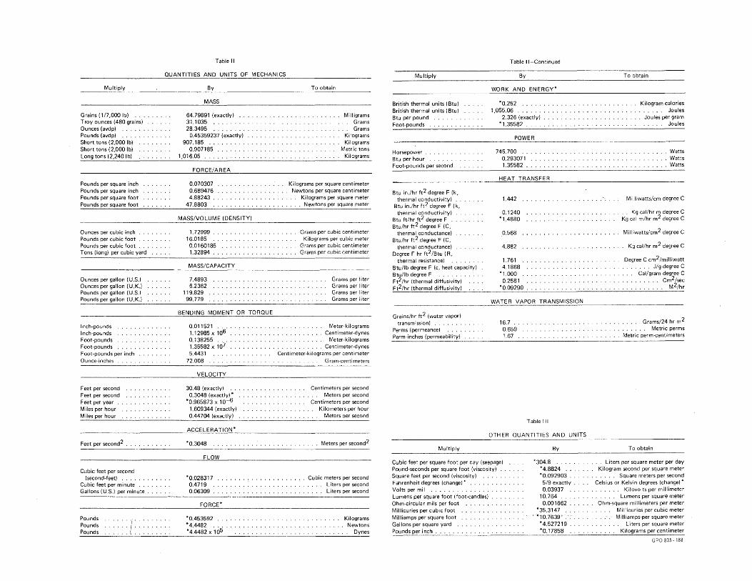
Table II
QUANTITIES AND UNITS OF MECHANICS
Multiply
Grains (1/7,000 lb) ..... Troy ounces (480 grains) Ounces (avdp) ......... . Pounds (avdp) .. Short tons (2,000 lb) Short tons (2,000 lb) Long tons (2,240 I b)
Pounds per square inch Pounds per square inch Pounds per square foot Pounds per square foot
Ounces per cubic inch ..... . Pounds per cubic foot .. . Pounds per cubic foot .. . Tons (long) per cubic yard
Ounces per gallon (U.S.) Ounces per gallon (U.K.) Pounds per gallon (U.S.) Pounds per gallon (U.K.)
Inch-pounds Inch-pounds Foot-pounds Foot-pounds .......... . Foot-pounds per inch Ounce-inches
Feet per second ...... . Feet per second ...... . Feet per year . Miles per hour Miles per hour
Feet per second2 .......... .
Cubic feet per second (second-feet) .....
Cubic feet per minute . Gallons (U.S.) per minute ....
Pounds Pounds Pounds ::::!::
By
MASS
64.79891 (exactly) 31.1035 ......... . 28.3495 ......... .
0.45359237 (exactly) 907.185 ..
0.907185 1,016.05 .
FORCE/AREA
0.070307 0.689476 4.88243
47.8803 .
MASS/VOLUME (DENSITY)
1.72999 16.0185
0.0160185 1.32894 ...
MASS/CAPACITY
7.4893 6.2362
119.829 99.779
BENDING MOMENT OR TORQUE
0.011521 .... 1.12985 X 10⁶ 0.138255 ... 1.35582 X 10⁷ 5.4431
72.008
VELOCITY
30.48 (exactly) 0.3048 (exactly)*
*0.965873 X 10⁻⁶
1.609344 (exactly) .. . 0.44704 (exactly) .... .
ACCELERATION*
*0.3048
FLOW
*0.028317 0.4719 0.06309 .
FORCE*
*0.453592 .. *4.4482 ... *4.4482 X 10⁵
To obtain
. Milligrams Grams
. .. Grams Kilograms
. Kilograms Metric tons
. Kilograms
Kilograms per square centimeter Newtons per square centimeter
Kilograms per square meter Newtons per square meter
Grams per cubic centimeter Kilograms per cubic meter
Grams per cubic centimeter Grams per cubic centimeter
Grams per I ter Grams per I ter Grams per Iter Grams per Iter
Meter-kilograms Centimeter-dynes
Meter-kilograms Centimeter-dynes
Centimeter-kilograms per centimeter Gram-centimeters
Centimeters per second . . Meters per second Centimeters per second
. . Kilometers per hour
. . . Meters per second
. Meters per second2
Cubic meters per second Liters per second
. . . . . Liters per second
Kilograms Newtons
Dynes
Multiply
British thermal units (Btu) British thermal units (Btu) Btu per pound Foot-pounds
Horsepower Btu per hour Foot-pounds per second
Btu in./hr ft2 degree F (k, thermal conductivity) ..
Btu in./hr tt2 degree F (k, thermal conductivity)
Btu h/hr ft2 degree F . Btu/hr ft2 degree F (C,
thermal conductance) Btu/hr ft2 degree F (C,
thermal conductance) Degree F hr ft2/Btu ( R,
thermal resistance) Btu/lb degree F (c, heat capacity) Btu/lb degree F ..... . Ft2/hr (thermal diffusivity) Ft2/hr (thermal diffusivity)
Grains/hr ft2 (water vapor) transmission)
Perms (permeance) Perm-inches (permeability)
Multiply
Table It-Continued
By
WORK AND ENERGY*
*0.252 ... . 1,055.06 ..... .
2.326 (exactly) * 1.35582 .
POWER
745.700 .. 0.293071 1.355B2 .
HEAT TRANSFER
1.442 ..
0.1240 *1.4880
0.568
4.882
1.761 4.1868
*1.000 .. 0.2581 .
*0.09290 .
WATER VAPOR TRANSMISSION
16.7 . 0.659 1.67
Table Ill
OTHER QUANTITIES AND UNITS
By
Cubic feet per square foot per day (seepage) Pound-seconds per square foot (viscosity) Square feet per second (viscosity) Fahrenheit degrees (change)* ..
*304.8 .. *4.8824 *0.092903 ... 5/9 exactly .. 0.03937
10.764 Volts per mil . . . . . . . ... Lumens per square foot (foot-candles) Ohm-circular mils per foot . Millicuries per cubic foot .. Milliamps per square foot .. Gallons per square yard .. . Pounds per inch ....... .
0.001662 *35.3147 .
, *10.7639' . *4.527219 ... *0.17858 ..
To obtain
Kilogram calories . . . . . Joules Joules per gram
Joules
Watts Watts Watts
M illiwattsfcm degree C
. .. Kg cal/hr m degree C Kg cal m/hr m2 degree C
Milliwatts/cm2 degree C
. Kg cal/hr m2 degree C
Degree C cm2/milliwatt . . . . Jig degree C . Gal/gram degree C . ...... cm2/sec . ....... M2/hr
Grams/24 hr m2 . . Metric perms
Metric perm-centimeters
To obtain
Liters per square meter per day Kilogram second per square meter
. . . . . . Square meters per second Celsius or Kelvin degrees (change)*
Kilovolts per millimeter . Lumens per square meter
Ohm-square millimeters per meter Millicuries per cubic meter M illiamps·per. square meter
Liters per square meter Kilograms per centimeter
GPO 835. 188
.............................. "" .................................................................................................................... .
ABSTRACT
. The magnitude and occurrence of ice problems encountered in winter operation of water conveyance facilities, pumping plants, and hydroelectric plants is not in direct proportion to the severity of the winter season. Instead, areas subject to intermittent freezing and thawing are usually more susceptible to the problems of floe ice, frazil ice, and anchor ice than are the areas in the far north. Many of these ice problems can be alleviated by proper use of current expertise in the design and operation of such facilities. For example, the successful operation of a diversion structure may depend upon its location on the river, the fore bay characteristics, the velocity, the trashrack submergence, trashrack heating, etc. These and other considerations are discussed in this report. (36 ref)
ABSTRACT
The magnitude and occurrence of ice problems encountered in winter operation of water conveyance facilities, pumping plants, and hydroelectric plants is not in direct proportion to the severity of the winter season. Instead, areas subject to intermittent freezing and thawing are usually more susceptible to the problems of floe ice, frazil ice, and anchor ice than are the areas in the far north. Many of these ice problems can be alleviated by proper use of current expertise in the design and operation of such facilities. For example, the successful operation of a diversion structure may depend upon its location on the river, the forebay characteristics, the velocity, the trash rack submergence, trashrack heating, etc. These and other considerations are discussed in this report (36 ref)
•••••••••••••••••••••••••.••••••••••••••••••••••••••••••••••••••••••••••••• : ...................................................... 4 •••••• ••••••••••••• t
ABSTRACT
The magnitude and occurrence of ice problems encountered in winter operation of water conveyance facilities~ pumping plants, and hydroelectric plants is not in direct proportion to the severity of the winter season. Instead, areas subject to intermittent freezing and thawing are usually more susceptible to the problems of floe ice, frazil ice, and anchor ice than are the areas in the far north. Many of these ice problems can be alleviated by proper use of current expertise in the design and operation of such facilities. For example, the successful operation of a diversion structure may depend upon its location on the river, the forebay characteristics, the velocity, the trashrack submergence, trashrack heating, etc. These and other considerations are discussed in this report, (36 ref)
.
ABSTRACT
The magnitude and occurrence of ice problems encountered in winter operation of water conveyance facilities, pumping plants, and hydroelectric plants is not in direct proportion to the severity of the winter season. Instead, areas subject to intermittent freezing and thawing are usually more susceptible to the problems of floe ice, frazil ice, and anchor ice than are the areas in the far north. Many of these ice problems can be alleviated by proper use of current expertise in the design and operation of such facilities. For example, the successful operation of a diversion structure may depend upon its location on the river, the forebay characteristics, the velocity, the trashrack submergence, trashrack heating, etc. These and other considerations are discussed in this report. (36 ref)
REC-ERC-74-19 Hayes, R B DESIGN AND OPERATION OF SHALLOW RIVER DIVERSIONS IN COLD REGIONS Bur Reclam Rep REC-ERC-"/4-19, Div Gen Res, Sept 1974. Bureau of Reclamation, Denver, 39 p, 15 fig, 1 tab, 36 ref, 2 append
DESCRIPTORS-/ *frazil ice/ *ice formation/ *floating ice/ anchor ice/ ice cover/ trashracks/ intake structures/ cold regions/ *ice prevention/ design criteria/ diversion structures/ velocity/ water conveyance/ seasonal variations/ operation and maintenance/ heating/ bibliographies
REC-ERC-74"19 Hayes, R B DESIGN AND OPERATION OF SHALLOW RIVER DIVERSIONS IN COLD REGIONS . Bur Reclam Rep REC-ERC-74-19, Div Gen Res, Sept 1974. Bureau of Reclamation, Der:~ver, 39 p, 15 fig, 1 tab, 36 ref, 2 append
DESCRIPTORS-/ *frazil ice/ *ice formation/ *floating ice/ anchor ice/ ice cover/ trashracks/ intake structures/ cold regions/ *ice prevention/ design criteria/ diversion structures/ velocity/ water conveyance/ seasonal variations/ operation and maintenance/ heating/ bibliographies
REC-ERC-74-19 Hayes, R B DESIGN AND OPERATION OF SHALLOW RIVER DIVERSIONS IN COLD REGIONS Bur Reclam Rep REC-ERC-74-·19, Div Gen Res, Sept 1974. Bureau of Reclamation, Denver, 39 p, 15 fig, 1 tab, 36 ref, 2 append
DESCRIPTORS-/ *frazil ice/ *ice formation/ *floating ice/ anchor ice/ ice cover/ trashracks/ intake structures/ cold regions/ *ice prevention/ design criteria/ diversion structures/ velocity/ water conveyance/ seasonal variations/ operation and maintenance/ heating/ bibliographies
REC-ERC-74-19 Hayes, R B DESIGN AND OPERATION OF SHALLOW RIVER DIVERSIONS IN COLD REGIONS Bur Reclam Rep REC-ERC-74-19, DiV Gen Res, Sept 1974. Bureau of Reclamation, Denver, 39 p, 15 fig, 1 tab, 36 ref, 2 append
DESCRIPTORS-/ *frazil ice/ *ice formation/ *floating ice/ anchor ice/ ice cover/ trashracks/ intake structures/ cold regions/ *ice prevention/ design criteria/ diversion structures/ velocity/ water conveyance/ seasonal variations/ operation and maintenance/ heating/ bibliographies


![[James Thurber] Alarms and Diversions](https://img.pdfslide.us/doc/110x75/55cf9bfd550346d033a821f0/james-thurber-alarms-and-diversions.jpg)