Embed Size (px)
Citation preview

Contact Infiltrator Systems Inc. 1-800-221-4436 for additional technical and product information. 11MARCH 2015
Design and Installation Manual for Infiltrator Chambers in Florida
The purpose of this product information sheet is to provide specific design and installation information pertinent for the use of Infiltrator products in Florida.
For more detailed design information, please contact Infiltrator Systems at 1-800-221-4436
Version March 16, 2015Approved Florida Department of Health, Onsite Sewage ProgramsApril 6, 2015
Florida
Infiltrator Chambers in FloridaINTRODUCTION 2
PRODUCTS 4
SYSTEM SIZING 8
CHAMBER CONFIGURATIONS 13
INSTALLATION INSTRUCTIONS 20
SPECIAL PROCEDURES 28
WARRANTY 31
Florida
Bartow
Belle Glade
CapeCanaveral
Clearwater
Crestview
Daytona Beach
Florida City
Fort Lauderdale
Fort Myers
Fort Pierce
Gainesville
Ocala
Jack-sonville
Key West
Lake City
Lakeland
Leesburg
Marianna
Miami
Naples
Orlando
PanamaCity
Pensacola
Perry
St Petersburg
Sarasota
Tallahassee
Tampa
West Palm Beach
St Augustine

Contact Infiltrator Systems Inc. 1-800-221-4436 for additional technical and product information.2
Quick4 Equalizer 36 StraightLock ChamberThe revolutionary patented Quick4 Equalizer 36 StraightLock Chamber is specifically designed for use in bed applications. The StraightLock connection forms a rigid joint that allows chamber rows to remain straight and resistant to movement during backfilling. The MultiPort™ endcap allows multiple piping options and eliminates pipe fittings.
Quick4 Equalizer® 36 ChamberThe patented Quick4 Equalizer 36 Chamber can be installed in a 24-inch wide trench. The chamber offers advanced contouring capability with its Contour Swivel Connection™. The patented MultiPort Endcap, with its six molded-in high and low inlets allows for maximum piping flexibility.
Equalizer 36 QuickCut ChamberThe Equalizer 36 QuickCut chamber features a unique premarked cut line, allowing you to create two chambers that are over 4 feet in length. This product innovation offers increased design and installation flexibility, while maintaining structural integrity and long-term performance. The chamber provides greater options for all sites, including tight or sloped lots.
Quick4 Equalizer 24 HD ChamberThe Equalizer 24 HD chamber was designed to provide exceptional strength when used in trench or bed applications. The chamber’s enhanced features, which include an increased wall thickness, structural x-ribs and reinforced connection joints, make it one of the strongest Quick4 chambers available today.
QUICK4 EQ36 STRAIGHTLOCK
EQUALIZER 36 QUICKCUT
INTRODUCTION
QUICK4 EQUALIZER 36
QUICK4 EQUALIZER 24
Contact Infiltrator Systems Inc. 1-800-221-4436 for additional technical and product information. 33
QUICK4 PLUS ENDCAP
QUICK4 PLUS ALL-IN-ONE 8 ENDCAP
QUICK4 PLUS EQ36 STRAIGHTLOCK LP CHAMBER
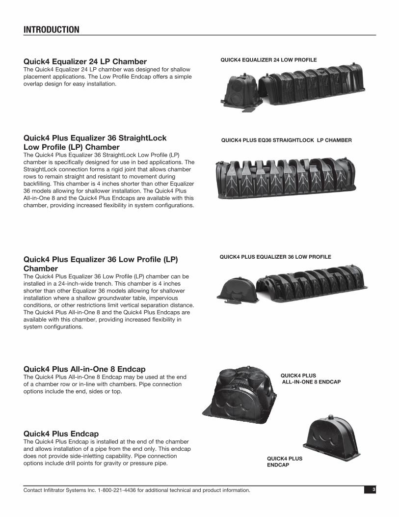
Quick4 Equalizer 24 LP ChamberThe Quick4 Equalizer 24 LP chamber was designed for shallow placement applications. The Low Profile Endcap offers a simple overlap design for easy installation.
Quick4 Plus Equalizer 36 StraightLock Low Profile (LP) ChamberThe Quick4 Plus Equalizer 36 StraightLock Low Profile (LP) chamber is specifically designed for use in bed applications. The StraightLock connection forms a rigid joint that allows chamber rows to remain straight and resistant to movement during backfilling. This chamber is 4 inches shorter than other Equalizer 36 models allowing for shallower installation. The Quick4 Plus All-in-One 8 and the Quick4 Plus Endcaps are available with this chamber, providing increased flexibility in system configurations.
Quick4 Plus Equalizer 36 Low Profile (LP) ChamberThe Quick4 Plus Equalizer 36 Low Profile (LP) chamber can be installed in a 24-inch-wide trench. This chamber is 4 inches shorter than other Equalizer 36 models allowing for shallower installation where a shallow groundwater table, impervious conditions, or other restrictions limit vertical separation distance. The Quick4 Plus All-in-One 8 and the Quick4 Plus Endcaps are available with this chamber, providing increased flexibility in system configurations.
Quick4 Plus All-in-One 8 EndcapThe Quick4 Plus All-in-One 8 Endcap may be used at the end of a chamber row or in-line with chambers. Pipe connection options include the end, sides or top.
Quick4 Plus EndcapThe Quick4 Plus Endcap is installed at the end of the chamber and allows installation of a pipe from the end only. This endcap does not provide side-inletting capability. Pipe connection options include drill points for gravity or pressure pipe.
INTRODUCTION
QUICK4 PLUS EQUALIZER 36 LOW PROFILE
QUICK4 EQUALIZER 24 LOW PROFILE

Contact Infiltrator Systems Inc. 1-800-221-4436 for additional technical and product information.4
SIDE AND END VIEWS(not to scale)
52"
16"
12"
6"
12"
22"
48"EFFECTIVE LENGTH
16"
12"
52"
16"
12"
6"
12"
22"
48"EFFECTIVE LENGTH
16"
12"
52"
16"
12"
6"
12"
22"
48"EFFECTIVE LENGTH
16"
12"
52"
16"
12"
6"
12"
22"
48"EFFECTIVE LENGTH
16"
12"
SIDE AND END VIEWS(not to scale)
EFFECTIVE LENGTH
INSPECTION PORT
22"
6"
12"
48"
INLET
SIDESIDE
OUTLET
6" INVERTEND CAP
22"
12"
16"
12"
EFFECTIVE LENGTH
INSPECTION PORT
22"
6"
12"
48"
INLET
SIDESIDE
OUTLET
6" INVERTEND CAP
22"
12"
16"
12"
EFFECTIVE LENGTH
INSPECTION PORT
22"
6"
12"
48"
INLET
SIDESIDE
OUTLET
6" INVERTEND CAP
22"
12"
16"
12"
FRONT VIEW SIDE VIEW
FRONT VIEW SIDE VIEW
Quick4 EQ36 StraightLock nominal chamber specificationsSize 22”W x 53”L x 12”HEffective Length 48”Invert Height 6”
Quick4 Equalizer 36 nominal chamber specificationsSize (W x L x H) 22”W x 53”L x 12”HEffective Length 48”Invert Height 6”
MULTIPORT ENDCAP(not to scale)
MULTIPORT ENDCAP(not to scale)
Quick4 Equalizer 36 StraightLock Chamber
Quick4 Equalizer 36 Chamber
PRODUCTS

Contact Infiltrator Systems Inc. 1-800-221-4436 for additional technical and product information. 55
12.25"
6" 6"
10.5"
SIDE AND END VIEWS(not to scale)
15ϒ1" OVERLAP AT LATCHING MECHANISM
13.75"
50" 50"
100"EFFECTIVE LENGTH 22"
19.4"AVG. INSIDE WIDTH
END PLATES (not to scale)
PART # EQ36-EN
Equalizer 36 QuickCut nominal chamber specificationsSize (W x L x H) 22”W x 100”L x 13.5”HEffective Length 100”Invert Height 6”
Quick4 Equalizer 24 HD nominal chamber specificationsSize (W x L x H) 16”W x 53”L x 11”HEffective Length 48”Invert Height 6”
SIDE AND END VIEWS(not to scale)
MULTIPORT ENDCAP(not to scale)
53"
48"EFFECTIVE LENGTH
16"
16"
6"
11"14"
11"
53"
48"EFFECTIVE LENGTH
16"
16"
6"
11"14"
11"
53"
48"EFFECTIVE LENGTH
16"
16"
6"
11"14"
11"
FRONT VIEW SIDE VIEW
48"EFFECTIVE LENGTH
16"
11"
Equalizer 36 QuickCut Chamber
Quick4 Equalizer 24 HD Chambers
PRODUCTS

Contact Infiltrator Systems Inc. 1-800-221-4436 for additional technical and product information.66
SIDE AND END VIEWS(not to scale)
14” ID
FRONT VIEW SIDE VIEW
(not to scale)
Quick4 Equalizer 24 Low Profile (LP) nominal chamber specifications
Size (W x L x H) 16”W x 53”L x 8”H
Effective Length 48”Invert Elevation 2”
Quick4 Plus Equalizer 36 StraightLock Low Profile (LP) ChambersSIDE AND END VIEWS(not to scale)
Quick4 Plus Equalizer 36 Low Profile (LP) ChambersSIDE AND END VIEWS(not to scale)
22"
8"
48"(EFFECTIVE LENGTH)
22"
8"
48"(EFFECTIVE LENGTH)
8"
18"
3.3"
6"
QUICK4 PLUS EQUALIZER 36 STRAIGHTLOCK LOW PROFILE (LP) CHAMBERS
8"
18"
3.3"
6"
22"
8"
48"(EFFECTIVE LENGTH)
22"
8"
48"(EFFECTIVE LENGTH)
8"
18"
3.3"
6"
QUICK4 PLUS EQUALIZER 36 STRAIGHTLOCK LOW PROFILE (LP) CHAMBERS
8"
18"
3.3"
6"
22"
8"
48"(EFFECTIVE LENGTH)
22"
8"
48"(EFFECTIVE LENGTH)
8"
18"
3.3"
6"
QUICK4 PLUS EQUALIZER 36 STRAIGHTLOCK LOW PROFILE (LP) CHAMBERS
8"
18"
3.3"
6"
SIDE VIEW
22"
8"
48"(EFFECTIVE LENGTH)
22"
8"
48"(EFFECTIVE LENGTH)
8"
18"
3.3"
6"
QUICK4 PLUS EQUALIZER 36 STRAIGHTLOCK LOW PROFILE (LP) CHAMBERS
8"
18"
3.3"
6"
22"
8"
48"(EFFECTIVE LENGTH)
22"
8"
48"(EFFECTIVE LENGTH)
8"
18"
3.3"
6"
QUICK4 PLUS EQUALIZER 36 STRAIGHTLOCK LOW PROFILE (LP) CHAMBERS
8"
18"
3.3"
6"
22"
8"
48"(EFFECTIVE LENGTH)
22"
8"
48"(EFFECTIVE LENGTH)
8"
18"
3.3"
6"
QUICK4 PLUS EQUALIZER 36 STRAIGHTLOCK LOW PROFILE (LP) CHAMBERS
8"
18"
3.3"
6"
Quick4 Plus Equalizer 36 Low Profile (LP)nominal chamber specifications
Size (W x L x H) 22”W x 53”L x 8”H
Effective Length 48”Invert Elevation 3.3” and 9”
22"
8"
48"(EFFECTIVE LENGTH)
22"
8"
48"(EFFECTIVE LENGTH)
8"
18"
3.3"
6"
QUICK4 PLUS EQUALIZER 36 STRAIGHTLOCK LOW PROFILE (LP) CHAMBERS
8"
18"
3.3"
6"
22"
8"
48"(EFFECTIVE LENGTH)
22"
8"
48"(EFFECTIVE LENGTH)
8"
18"
3.3"
6"
QUICK4 PLUS EQUALIZER 36 STRAIGHTLOCK LOW PROFILE (LP) CHAMBERS
8"
18"
3.3"
6"
LOW PROFILE ENDCAP(not to scale)Quick4 Equalizer 24 Low Profile (LP)
nominal chamber specifications
Size (W x L x H) 22”W x 53”L x 8”H
Effective Length 48”Invert Elevation 3.3” and 9”
Quick4 Equalizer 24 Low Profile (LP) Chamber
LOW PROFILE ENDCAP(not to scale)
FRONT VIEW SIDE VIEW
FRONT VIEW
PRODUCTS

Contact Infiltrator Systems Inc. 1-800-221-4436 for additional technical and product information. 77
Quick4 Plus All-in-One 8 Endcap
9"
18"
10"
18"
15"
3.3" 3.3"
Quick4 Plus Endcap
17.8"
4.5"
SIDE AND END VIEWS(not to scale)
17.8"
4.5"
FRONT VIEW SIDE VIEW
FRONT VIEW SIDE VIEW
SIDE AND END VIEWS(not to scale)
PRODUCTS

Contact Infiltrator Systems Inc. 1-800-221-4436 for additional technical and product information.88
TABLE 1: CHAMBER RATINGS
TABLE 2: BED SYSTEMS WIDTH USING MINIMUM SEPARATION
NOTES: 1. Minimum spacing between chambers is 0”. Chambers may be placed edge-to-edge. 2. Minimum space between chambers is 4”. 3. Measurements are to the outside edge of chamber. 4. On replaced fill, the one foot perimeter area required for dig-out around the system should be measured from end of chambers and not the
endcaps. Endcaps are not given any credit for drainfield area and can be placed within soil replacement perimeter.
ChamberRating
(sf/chamber)Trench Width
(in)Min. Bed Spacing
(in)Quick4 EQ36 Straightlock (22" x 48" x 12") 12.00 24 4
Quick4 Plus EQ36 Straightlock LP (22" x 48" x 8") 11.32 24 0
Quick4 EQ36 (22" x 48" x 12") 12.00 24 4
Quick4 Plus EQ36 LP (22" x 48" x 8") 11.32 24 0
Equalizer 36 QuickCut (22" x 100" x 13.5") 25.00 24 4
Quick4 Equalizer 24 HD (16" x 48" x 11") 8.00 18-24 0
Quick4 Equalizer 24 LP (16" x 48" x 8") 7.28 18-24 0
Side-by-Side Quick4 Equalizer 24 HD 8.57 36 Trench Only
Side-by-Side Quick4 Equalizer 24 LP 7.80 36 Trench Only
TABLE 3: TRENCH SYSTEM WIDTH USING 2-FOOT SEPARATION*
No. of Trenches 22” Chamber System Width 16” Chamber System WidthQ4 EQ24 and Q4 EQ24 LP
Side-by-Side System Width2 5' 8" 4' 8" 8’3 9' 6" 8' 0" 13’4 13' 4" 11' 4" 18’5 17' 2" 14' 8" 23’6 21' 0" 18' 0" 28’7 24' 10" 21' 4" 33’8 28' 8" 24' 8" 38’9 32' 6" 28' 0" 43’
10 36' 4" 31' 4" 48’NOTES: 1. For 22-inch-wide products, add 3’-10” for each additional trench in excess of 10. 2. For 16-inch-wide products, add 3’-4” for each additional trench in excess of 10. 3. For side-by-side products, add 5’ for each additional trench in excess of 10. 4. Measurements are to outside edge of chamber.
No. of Rows Quick4 Plus EQ36 LP1Quick4 EQ24,
Quick4 EQ24 LP1
Equalizer 36 QuickCut, Quick4 EQ 362
2 3' 8" 2' 8" 4' 0"3 5' 6" 4' 0" 6' 2"4 7' 4" 5' 4" 8' 4"5 9' 2" 6' 8" 10' 6"6 11' 0" 8' 0" 12' 8"7 12' 10" 9' 4" 14' 10"8 14' 8" 10' 8" 17' 0"9 16' 6" 12' 0" 19' 2"
10 18' 4" 13' 4" 21' 4"
Chamber System Sizing
SYSTEM SIZING

Contact Infiltrator Systems Inc. 1-800-221-4436 for additional technical and product information. 99
TABLE 4: QUICK4 EQ36 STRAIGHTLOCK AND QUICK4 EQ36 CHAMBER LENGTHS AND RATING(TRENCH OR BED SYSTEM CONFIGURATION)
No. of Chambers Length (ft ) Rating (ft2 )
1 4.0 12.02 8.0 24.03 12.0 36.04 16.0 48.05 20.0 60.06 24.0 72.07 28.0 84.08 32.0 96.09 36.0 108.010 40.0 120.011 44.0 132.012 48.0 144.013 52.0 156.014 56.0 168.015 60.0 180.016 64.0 192.017 68.0 204.018 72.0 216.019 76.0 228.020 80.0 240.021 84.0 252.022 88.0 264.023 92.0 276.024 96.0 288.025 100.0 300.026 104 312.027 108 324.028 112 336.029 116 348.030 120 360.031 124 372.032 128 384.033 132 396.034 136 408.035 140 420.036 144 432.037 148 444.038 152 456.039 156 468.0
Note: For minimum sizing on standard and split systems (grey water) refer to Chapter 64E-6 Florida Administrative Code.
Note: Line lengths can not exceed 100 ft except in low-pressure dosing system installations.
TABLE 5: QUICK4 PLUS EQ36 LP AND QUICK4 PLUS EQ36 LP SL CHAMBER LENGTHS AND RATING(TRENCH OR BED SYSTEM CONFIGURATION)
No. of Chambers Length (ft ) Rating (ft2 )
1 4.0 11.32 8.0 22.63 12.0 33.94 16.0 45.25 20.0 56.56 24.0 67.87 28.0 79.18 32.0 90.49 36.0 101.710 40.0 113.011 44.0 124.312 48.0 135.613 52.0 146.914 56.0 158.215 60.0 169.516 64.0 180.817 68.0 192.118 72.0 203.419 76.0 214.720 80.0 226.021 84.0 237.322 88.0 248.623 92.0 259.924 96.0 271.225 100.0 282.526 104 293.827 108 305.128 112 316.429 116 327.730 120 339.031 124 350.332 128 361.633 132 372.934 136 384.235 140 395.536 144 406.837 148 418.138 152 429.439 156 440.7
Note: For minimum sizing on standard and split systems (grey water) refer to Chapter 64E-6 Florida Administrative Code.
Note: Line lengths can not exceed 100 ft except in low-pressure dosing system installations.
Chamber System Sizing
SYSTEM SIZING

Contact Infiltrator Systems Inc. 1-800-221-4436 for additional technical and product information.1010
TABLE 7: QUICK4 EQ24 HD CHAMBER LENGTHS AND RATING (SIDE-BY-SIDE TRENCH CONFIGURATION)
Note: For minimum sizing on standard and split systems (grey water) refer to Chapter 64E-6 Florida Administrative Code.
Note: Line lengths can not exceed 100 ft except in low-pressure dosing system installations.
No. of Chambers Length (ft ) Rating (ft2)
2 4.0 17.14 8.0 34.36 12.0 51.48 16.0 68.6
10 20.0 85.712 24.0 102.814 28.0 120.016 32.0 137.118 36.0 154.320 40.0 171.422 44.0 188.524 48.0 205.726 52.0 222.828 56.0 240.030 60.0 257.132 64.0 274.234 68.0 291.436 72.0 308.538 76.0 325.740 80.0 342.842 84.0 359.944 88.0 377.146 92.0 394.248 96.0 411.450 100.0 428.552 104 445.654 108 462.856 112 479.958 116 497.160 120 514.262 124 531.364 128 548.566 132 565.668 136 582.870 140 599.972 144 617.074 148 634.276 152 651.378 156 668.5
No. of Chambers Length (ft ) Rating (ft2)
1 8’ 4” 25.011⁄2 12’ 6” 37.52 16’ 8” 50.0
21⁄2 21’ 1” 62.53 25’ 0” 75.0
31⁄2 29’ 5” 87.54 33’ 7” 100.0
41⁄2 37’ 9” 112.55 42’ 1” 125.0
51⁄2 46’ 3” 137.56 50’ 0” 150.0
61⁄2 54’ 7” 162.57 58’ 9” 175.0
71⁄2 63’ 2” 187.58 67’ 4” 200.0
81⁄2 71’ 6” 212.59 75’ 0” 225.0
91⁄2 80’ 0” 237.510 84’ 2” 250.0
101⁄2 88’ 4” 262.511 92’ 6” 275.0
111⁄2 96’ 8” 287.512 100’ 0” 300.0
121⁄2 105’ 3” 312.513 109’ 5” 325.0
131⁄2 113’ 7” 337.514 117’ 9” 350.0
141⁄2 122’ 1” 362.515 126’ 3” 375.0
151⁄2 130’ 5” 387.516 134’ 7” 400.0
161⁄2 138’ 9” 412.517 143’ 1” 425.0
171⁄2 147’ 4” 437.518 151’ 6” 450.0
181⁄2 155’ 8” 462.519 160’ 0” 475.0
191⁄2 164’ 2” 487.520 168’ 4” 500.0
Note: Full EQ36 QuickCut Chambers have a rating of 25 ft2, half chambers have a rating of 12.5 ft2.
Note: Line lengths can not exceed 100 ft except in low-pressure dosing system installations.
TABLE 6: EQ36 QUICKCUT CHAMBER LENGTHS AND RATING (TRENCH OR BED SYSTEM CONFIGURATION)
Chamber System Sizing
SYSTEM SIZING

Contact Infiltrator Systems Inc. 1-800-221-4436 for additional technical and product information. 1111
No. of Chambers Length (ft ) Rating (ft2)
1 4.0 8.02 8.0 16.03 12.0 24.04 16.0 32.05 20.0 40.06 24.0 48.07 28.0 56.08 32.0 64.09 36.0 72.0
10 40.0 80.011 44.0 88.012 48.0 96.013 52.0 104.014 56.0 112.015 60.0 120.016 64.0 128.017 68.0 136.018 72.0 144.019 76.0 152.020 80.0 160.021 84.0 168.022 88.0 176.023 92.0 184.024 96.0 192.025 100.0 200.026 104 208.027 108 216.028 112 224.029 116 232.030 120 240.031 124 248.032 128 256.033 132 264.034 136 272.035 140 280.036 144 288.037 148 296.038 152 304.039 156 312.0
TABLE 8: QUICK4 EQ24 HD CHAMBER LENGTHS AND RATING(TRENCH OR BED CONFIGURATION)
Note: For minimum sizing on standard and split systems (grey water) refer to Chapter 64E-6 Florida Administrative Code.
Note: Line lengths can not exceed 100 ft except in low-pressure dosing system installations.
TABLE 9: QUICK4 EQ24 LP CHAMBER LENGTHS AND RATING(SIDE-BY-SIDE TRENCH CONFIGURATION)
Note: For minimum sizing on standard and split systems (grey water) refer to Chapter 64E-6 Florida Administrative Code.
Note: Line lengths can not exceed 100 ft except in low-pressure dosing system installations.
No. of Chambers Length (ft ) Rating (ft2)
2 4.0 15.64 8.0 31.26 12.0 46.88 16.0 62.4
10 20.0 78.012 24.0 93.614 28.0 109.216 32.0 124.818 36.0 140.420 40.0 156.022 44.0 171.624 48.0 187.226 52.0 202.828 56.0 218.430 60.0 234.032 64.0 249.634 68.0 265.236 72.0 280.838 76.0 296.440 80.0 312.042 84.0 327.644 88.0 343.246 92.0 358.848 96.0 374.450 100.0 390.052 104 405.654 108 421.256 112 436.858 116 452.460 120 468.062 124 483.664 128 499.266 132 514.868 136 530.470 140 546.072 144 561.674 148 577.276 152 592.878 156 608.4
SYSTEM SIZING

Contact Infiltrator Systems Inc. 1-800-221-4436 for additional technical and product information.12
No. of Chambers Length (ft ) Rating (ft2)
1 4.0 7.32 8.0 14.63 12.0 21.84 16.0 29.15 20.0 36.46 24.0 43.77 28.0 51.08 32.0 58.29 36.0 65.5
10 40.0 72.811 44.0 80.112 48.0 87.413 52.0 94.614 56.0 101.915 60.0 109.216 64.0 116.517 68.0 123.818 72.0 131.019 76.0 138.320 80.0 145.621 84.0 152.922 88.0 160.223 92.0 167.424 96.0 174.725 100.0 182.026 104 189.327 108 196.628 112 203.829 116 211.130 120 218.431 124 225.732 128 233.033 132 240.234 136 247.535 140 254.836 144 262.137 148 269.438 152 276.639 156 283.9
TABLE 10: QUICK4 EQ24 LP CHAMBER LENGTHS AND RATING(TRENCH OR BED CONFIGURATION)
Note: For minimum sizing on standard and split systems (grey water) refer to Chapter 64E-6 Florida Administrative Code.
Note: Line lengths can not exceed 100 ft except in low-pressure dosing system installations.
Chamber System Sizing
SYSTEM SIZING

Contact Infiltrator Systems Inc. 1-800-221-4436 for additional technical and product information. 1313
PLAN VIEW: GRAVITY OR LIFT DOSE(not to scale)
Quick4 Equalizer 24 LP Mound Configurations
CROSS SECTION(not to scale)
CHAMBER CONFIGURATIONS
6"8"
16"
PRESSURE PIPEPER DESIGN INFILTRATOR SYSTEMS, INC.
QUICK4 EQUALIZER 24 LP CHAMBER (TYP.)
FILL TO MEET PLAN SPECIFICATIONSINSTALL FILL PER ISI FILL INSTRUCTIONS
QUICK4 EQUALIZER 24 LP CHAMBERSEND CAPS (TYP.)
PVC HEADER PIPEAND FITTINGS
PRESSURE PIPESIZED PER DESIGN
PUMP CHAMBERIF REQUIRED(IM-540 SHOWN)
WATER TABLE
PER CODEPER DESIGN
EXISTING GRADE
SLOPEPER DESIGN
ESTABLISH VEGETATIVE COVER (TYP.)
24" STATE MINIMUM SEPARATION DISTANCE
TO WATER TABLE
SEPTIC TANK(IM-1060 SHOWN)
INFILTRATOR IM-SERIES TANKAVAILABLE IN 500, 1000 & 1500 gal.
Notes: 1. Length and number of chamber rows per design.2. Design configuration applies to pump, LLP and dosing systems.

Contact Infiltrator Systems Inc. 1-800-221-4436 for additional technical and product information.1414
CROSS SECTION(not to scale)
(not to scale)
Quick4 Equalizer 24 LP Trench Configurations
CHAMBER CONFIGURATIONS
Notes: 1. Length and number of trenches per design.2. Trench installations require a separation of 2 feet edge to edge.3. Design configuration applies to pump, LLP and dosing systems.4. Drill opening at bottom of endcap to connect chambers at endcap.
SINGLE TRENCH INSTALLATIONSIDE-BY-SIDE INSTALLATION
MOUND FOR PROPER DRAINAGE &ESTABLISH VEGETATIVE COVER
QUICK4 EQUALIZER 24LP CHAMBER (TYP.)
MOUND FOR PROPER DRAINAGE &ESTABLISH VEGETATIVE COVER
QUICK4 EQUALIZER 24LP CHAMBER (TYP.)
6" MIN.
8"
16"
6" MIN.
8"
16"
36"
4"- 6"
QUICK4 EQUALIZER 24 LP CHAMBERS (TYP.)
SEPTIC TANK(IM-1060 SHOWN)
INFILTRATOR IM-SERIES TANKAVAILABLE IN 500, 1000 & 1500 gal.
PUMP CHAMBERIF REQUIRED(IM-540 SHOWN)
QUICK4 EQUALIZER 24 LPCHAMBER ENDCAP (TYP.)
36"
24"
HEADER PIPE AND FITTINGS

Contact Infiltrator Systems Inc. 1-800-221-4436 for additional technical and product information. 1515
CHAMBER CONFIGURATIONS
PLAN VIEW: GRAVITY OR LIFT DOSE(not to scale)
CROSS SECTION(not to scale)
Quick4 Equalizer 36 Mound Configurations
Notes: 1. Length and number of chamber rows per design.2. Design configuration applies to pump, LLP and dosing systems.3. Looping the distal end is required by 64E-6.014 (5) (i).4. A 4”-6” space is required between chamber rows.
6"12"
22"
PRESSURE PIPEPER DESIGN INFILTRATOR SYSTEMS, INC.
QUICK4 EQUALIZER 36 CHAMBER (TYP.)
FILL TO MEET PLAN SPECIFICATIONSINSTALL FILL PER ISI FILL INSTRUCTIONS
QUICK4 EQUALIZER 36 CHAMBERSEND CAPS (TYP.)
PVC HEADER PIPEAND FITTINGS
PRESSURE PIPESIZED PER DESIGN
PUMP CHAMBERIF REQUIRED(IM-540 SHOWN)
4"- 6"APPROX.
WATER TABLE
PER CODEPER DESIGN
EXISTING GRADE
SLOPEPER DESIGN
ESTABLISH VEGETATIVE COVER (TYP.)
24" STATE MINIMUM SEPARATION DISTANCE
TO WATER TABLE
SEPTIC TANK(IM-1060 SHOWN)
INFILTRATOR IM-SERIES TANKAVAILABLE IN 500, 1000 & 1500 gal.

Contact Infiltrator Systems Inc. 1-800-221-4436 for additional technical and product information.16
PLAN VIEW: GRAVITY OR LIFT DOSE(not to scale)
CROSS SECTION(not to scale)
Note: Quick4 Equalizer 36 StraightLock Chambers can also be used in these configurations.
Quick4 Equalizer 36 Bed Configurations
CHAMBER CONFIGURATIONS
MOUND FOR PROPER DRAINAGEESTABLISH VEGETATIVE COVER
22"
24"
SEPTIC TANK(IM-1060 SHOWN)
INFILTRATOR IM-SERIES TANKAVAILABLE IN 500, 1000 & 1500 gal.END CAPS (TYP.)
PVC HEADER PIPEAND FITTINGS
PRESSURE PIPESIZED PER DESIGN
QUICK4 EQUALIZER 36END PLATES (TYP.)
QUICK4 EQUALIZER 36 CHAMBERS24" MIN.4" PVC
6" MIN.
12"18" MIN.
PUMP CHAMBERIF REQUIRED(IM-540 SHOWN)
24" MIN.QUICK4EQUALIZER 36CHAMBER (TYP.)
USE BOTTOM TEAR OUTSEALS TO LOOP ENDS
Notes: 1. Length and number of chamber rows per design.2. Design configuration applies to pump, LLP and dosing systems.3. Looping the distal end is required by 64E-6.014 (5) (i).4. A 4”-6” space is required between chamber rows.
22"
6" MIN.
4"-6"APPROX
12"18" MIN.
QUICK4 EQUALIZER 36 CHAMBERSEND CAPS (TYP.)
4" PVC HEADER PIPEAND FITTINGS
PUMP CHAMBERIF REQUIRED(IM-540 SHOWN)
LOOP ENDSENDCAP-TO-ENDCAPAT BOTTOM INVERT(TYP.)
NATIVE BACKFILLOR PER DESIGN
GRADE FOR PROPER DRAINAGE
QUICK4 EQUALIZER 36 CHAMBERS (TYP.)
SEPTIC TANK(IM-1060 SHOWN)
INFILTRATOR IM-SERIES TANKAVAILABLE IN 500, 1000 & 1500 gal.

Contact Infiltrator Systems Inc. 1-800-221-4436 for additional technical and product information. 1717
CROSS SECTION(not to scale)
PLAN VIEW: GRAVITY OR LIFT DOSE(not to scale)
Notes:1. Length and number of trenches per design.2. Trench installations require a separation of 2 feet edge to edge.3. Design configuration applies to pump, LLP and dosing systems.4. Quick4 Equalizer 36 StraightLock Chambers can also be used in all Quick4 Equalizer 36 configurations.5. Looping the distal end is not required by code, however it will ensure equal distribution to all lines.
Quick4 Equalizer 36 Trench Configurations
CHAMBER CONFIGURATIONS
MOUND FOR PROPER DRAINAGEESTABLISH VEGETATIVE COVER
22"
24"
SEPTIC TANK(IM-1060 SHOWN)
INFILTRATOR IM-SERIES TANKAVAILABLE IN 500, 1000 & 1500 gal.END CAPS (TYP.)
PVC HEADER PIPEAND FITTINGS
PRESSURE PIPESIZED PER DESIGN
QUICK4 EQUALIZER 36END PLATES (TYP.)
QUICK4 EQUALIZER 36 CHAMBERS24" MIN.4" PVC
6" MIN.
12"18" MIN.
PUMP CHAMBERIF REQUIRED(IM-540 SHOWN)
24" MIN.QUICK4EQUALIZER 36CHAMBER (TYP.)
USE BOTTOM TEAR OUTSEALS TO LOOP ENDS

Contact Infiltrator Systems Inc. 1-800-221-4436 for additional technical and product information.18
PLAN VIEW: GRAVITY OR LIFT DOSE(not to scale)
CROSS SECTION(not to scale)
Quick4 Plus Equalizer 36 LP Bed Configurations
CHAMBER CONFIGURATIONS
NATIVE BACKFILLOR PER DESIGN
SEPTIC TANK(IM-1060 SHOWN)
INFILTRATOR IM-SERIES TANKAVAILABLE IN 500, 1000 & 1500 gal.
4" PVC HEADER PIPEAND FITTINGS
QUICK4 PLUS ALL-IN-ONE 8ENDCAP (TYP.)
PUMP CHAMBERIF REQUIRED(IM-540 SHOWN)
22" QUICK4 PLUS EQUALIZER 36 LPCHAMBERS (TYP.)
GRADE FOR PROPER DRAINAGE
6" MIN.
8"
DRILL OPENING AT BOTTOMOF ENDCAP TO LOOP ENDS
QUICK4 PLUS EQUALIZER 36 LP CHAMBERS
Notes: 1. Length and number of chamber rows per design.2. Design configuration applies to pump, LLP and dosing systems.3. Looping the distal end is required by 64E-6.014 (5)(i).4. Quick4 Plus Equalizer 36 StraightLock LP Chambers can also be used in all Quick4 Plus Equalizer 36 LP configurations.5. Endcaps may be Quick4 Plus Endcap or Quick4 Plus All-in-One 8 Endcap, depending upon piping configurations.
Contact Infiltrator Systems Inc. 1-800-221-4436 for additional technical and product information. 1919
CROSS SECTION(not to scale)
PLAN VIEW: GRAVITY OR LIFT DOSE(not to scale)
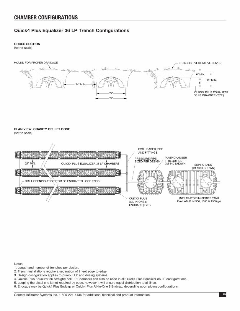
Quick4 Plus Equalizer 36 LP Trench Configurations
CHAMBER CONFIGURATIONS
Notes:1. Length and number of trenches per design.2. Trench installations require a separation of 2 feet edge to edge.3. Design configuration applies to pump, LLP and dosing systems.4. Quick4 Plus Equalizer 36 StraightLock LP Chambers can also be used in all Quick4 Plus Equalizer 36 LP configurations.5. Looping the distal end is not required by code, however it will ensure equal distribution to all lines.6. Endcaps may be Quick4 Plus Endcap or Quick4 Plus All-in-One 8 Endcap, depending upon piping configurations.
22"
24"
24" MIN. 8"
6" MIN.
14" MIN.
PUMP CHAMBERIF REQUIRED(IM-540 SHOWN)
DRILL OPENING AT BOTTOM OF ENDCAP TO LOOP ENDS
24" MIN.
PVC HEADER PIPEAND FITTINGS
PRESSURE PIPESIZED PER DESIGN
QUICK4 PLUS EQUALIZER 36 LP CHAMBERS
QUICK4 PLUS ALL-IN-ONE 8ENDCAPS (TYP.)
MOUND FOR PROPER DRAINAGE ESTABLISH VEGETATIVE COVER
QUICK4 PLUS EQUALIZER 36 LP CHAMBER (TYP.)
SEPTIC TANK(IM-1060 SHOWN)
INFILTRATOR IM-SERIES TANKAVAILABLE IN 500, 1000 & 1500 gal.
Contact Infiltrator Systems Inc. 1-800-221-4436 for additional technical and product information.2020
Excavating and Preparing the SiteNOTE: A State of Florida Department of Health Construction Permit (Form DH 4016) must be obtained before any system is constructed, modified or repaired. Form DH 4016 will specify all necessary information for constructing and repairing an onsite sewage system. Tank/drain field size, elevations, system configurations, and fill/excavation required can all be found on this form.
1. Stake out the location of drainfield area. Set the elevations of the tank, pipe, and drainfield bottom in accordance with specifications on Form DH 4016. 2. Excavate and level drainfield area. NOTE: The bed should be installed level or no more than 1” per 10’ of fall per Chapter 64E-6 of the Florida Administrative Code.
Before You BeginQuick4 EQ36 StraightLock (SL), Quick4 Plus EQ36 StraightLock Low Profile (LP) and Quick4 Equalizer 24 Low Profile (LP) Chambers may only be installed according to state and/or local regulations. If unsure of the installation requirements for a particular site, be sure to contact your local regulator. Like conventional systems, the soil and site conditions must be approved prior to installation. Conduct a thorough site evaluation to determine the proper sizing and siting of the system before installation.
These guidelines for construction machinery must be followed during installation: Avoid direct contact with chambers when using construction
equipment. Chambers require a 12-inch minimum of compacted cover to support a wheel load rating of 16,000 lbs/axle or equivalent to an H-10 AASHTO load rating.
Only drive across the system when necessary. Never drive down the length of the system. To avoid additional soil compaction, never drive heavy
vehicles over the completed system.
Materials and Equipment Needed Quick4 EQ36 StraightLock, Quick4 Plus EQ36
StraightLock LP, or Q4 EQ24 LP chambers MultiPort, Quick4 Plus All-in-One 8, Quick4 Plus,
or Quick4 Low Profile Endcaps 4” Diameter Pipe for Header and Inlet Backhoe / Excavator Laser, Transit, or Level Shovel and Rake Tape Measure Utility Knife / Screwdriver Screw Gun* 2-inch Drywall Screws**Optional
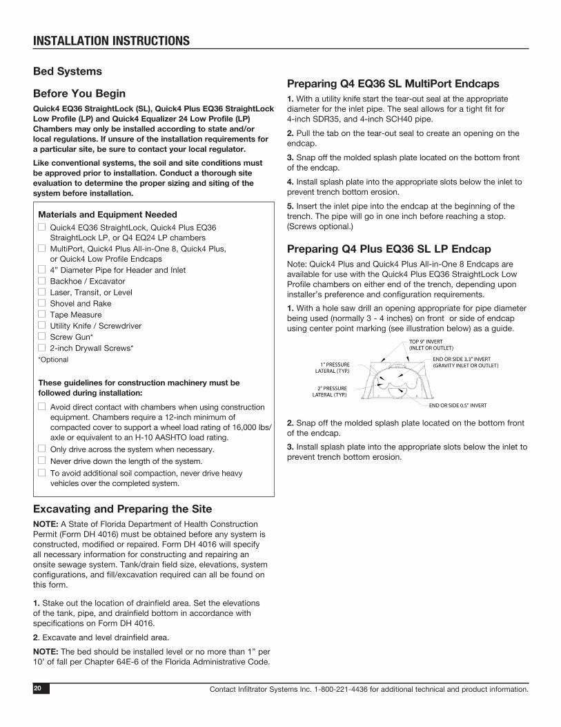
Preparing Q4 Plus EQ36 SL LP EndcapNote: Quick4 Plus and Quick4 Plus All-in-One 8 Endcaps are available for use with the Quick4 Plus EQ36 StraightLock Low Profile chambers on either end of the trench, depending upon installer’s preference and configuration requirements.1. With a hole saw drill an opening appropriate for pipe diameter being used (normally 3 - 4 inches) on front or side of endcap using center point marking (see illustration below) as a guide.
2. Snap off the molded splash plate located on the bottom front of the endcap.3. Install splash plate into the appropriate slots below the inlet to prevent trench bottom erosion.
Preparing Q4 EQ36 SL MultiPort Endcaps1. With a utility knife start the tear-out seal at the appropriate diameter for the inlet pipe. The seal allows for a tight fit for 4-inch SDR35, and 4-inch SCH40 pipe.2. Pull the tab on the tear-out seal to create an opening on the endcap.3. Snap off the molded splash plate located on the bottom front of the endcap.4. Install splash plate into the appropriate slots below the inlet to prevent trench bottom erosion.5. Insert the inlet pipe into the endcap at the beginning of the trench. The pipe will go in one inch before reaching a stop. (Screws optional.)
NOT TO SCALE
QUICK4 ALL IN ONE 8 ENDCAP
7/7/2011LMB
1 of 1DH
Drawing No. 1
1" PRESSURELATERAL (TYP.)
2" PRESSURELATERAL (TYP.)
TOP 9" INVERT(INLET OR OUTLET)
END OR SIDE 3.3" INVERT(GRAVITY INLET OR OUTLET)
END OR SIDE 0.5" INVERT
Bed Systems
INSTALLATION INSTRUCTIONS

Contact Infiltrator Systems Inc. 1-800-221-4436 for additional technical and product information. 21
Preparing Q4 EQ24 LP Endcap1. With a hole saw drill a opening appropriate to the pipe diameter being used (normally 3 to 4 inches) on the front of the endcap.2. Snap off the molded splash plate located on the bottom front of the endcap. 3. Install splash plate into the appropriate slots below the inlet to prevent trench bottom erosion.
Installing the System with Q4 EQ36 SL 1. Place the first chamber into the excavated and leveled area with the chamber-end marked “INLET” facing the tank/header. 2. Place the next chamber (inlet end facing tank/header) onto the previous one by overlapping the raised corrugation. Note: If installing a bed system, check the spacing between chambers to ensure approx. 4 to 6 inches of separation.3. To connect chambers and engage Straight-Lock connection, simply push down on the chamber with your hand until it snaps into place. Note locking tab engage through the opening in the chamber corrugation.4. Continue installing chambers until the system is completed. Note: Due to various site locations, if chambers are installed with inlet side toward distal end, this will not affect performance.
Attaching the Q4 EQ36 SL MultiPort Endcap1. Lift up the open end of the chamber while sliding the endcap under the chamber.2. Align the raised corrugation and lower the chamber so that it overlaps the endcap.Note: The endcap should be overlapped by the chamber on both the inlet and outlet ends. Optional: Secure the endcap in place with a drywall screw.
21
1Slide endcap under chamber.
3
Engage the connection.
Bed Systems
2Connect the chambers.
Installing the System with Q4 Plus EQ36 SL LP1. Place the first chamber into the excavated and leveled area.2. Place the back edge of the endcap over the inlet end of the first chamber. Be sure to line up the locking pins on the top of both the chamber and endcap.Optional: Fasten the endcap to the chamber with a screw at the top of endcap.3. Insert the inlet pipe 2.5 inches into the opening on the front of the endcap.4. Lift and place the end of the next chamber onto the previous chamber by holding it at a 45-degree angle. Line up the chamber end between the connector hook and locking pin at the top of the first chamber. Lower the chamber to the ground to connect the chambers. Note: When the chamber end is placed between the connector hook and locking pin at a 45-degree angle, the pin will be visible from the back side of the chamber. Note: The connector hook serves as a guide to ensure proper connection and does not add structural integrity to the chamber joint. Broken hooks will not affect the structure or void the warranty.5. Continue connecting chambers until the system is completed.Note: As chambers are installed, verify they are level or have the prescribed slope.
2Place endcap inlet end.
3
Insert inlet pipe.
4
Connect chambers.
INSTALLATION INSTRUCTIONS
Contact Infiltrator Systems Inc. 1-800-221-4436 for additional technical and product information.2222
Bed Systems
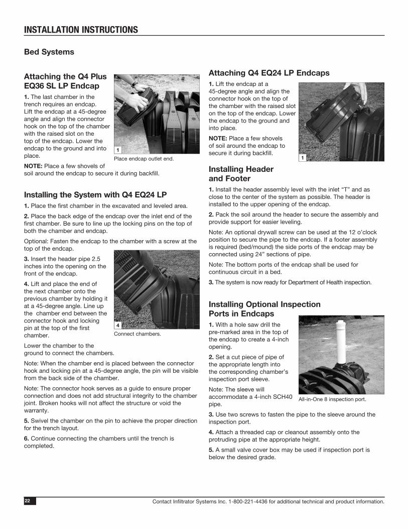
Attaching the Q4 Plus EQ36 SL LP Endcap1. The last chamber in the trench requires an endcap. Lift the endcap at a 45-degree angle and align the connector hook on the top of the chamber with the raised slot on the top of the endcap. Lower the endcap to the ground and into place.NOTE: Place a few shovels of soil around the endcap to secure it during backfill.
Installing the System with Q4 EQ24 LP1. Place the first chamber in the excavated and leveled area.2. Place the back edge of the endcap over the inlet end of the first chamber. Be sure to line up the locking pins on the top of both the chamber and endcap.Optional: Fasten the endcap to the chamber with a screw at the top of the endcap.3. Insert the header pipe 2.5 inches into the opening on the front of the endcap. 4. Lift and place the end of the next chamber onto the previous chamber by holding it at a 45-degree angle. Line up the chamber end between the connector hook and locking pin at the top of the first chamber. Lower the chamber to the ground to connect the chambers.Note: When the chamber end is placed between the connector hook and locking pin at a 45-degree angle, the pin will be visible from the back side of the chamber. Note: The connector hook serves as a guide to ensure proper connection and does not add structural integrity to the chamber joint. Broken hooks will not affect the structure or void the warranty.5. Swivel the chamber on the pin to achieve the proper direction for the trench layout. 6. Continue connecting the chambers until the trench is completed.
1Place endcap outlet end.
4Connect chambers.
Attaching Q4 EQ24 LP Endcaps1. Lift the endcap at a 45-degree angle and align the connector hook on the top of the chamber with the raised slot on the top of the endcap. Lower the endcap to the ground and into place. NOTE: Place a few shovels of soil around the endcap to secure it during backfill.
Installing Header and Footer1. Install the header assembly level with the inlet “T” and as close to the center of the system as possible. The header is installed to the upper opening of the endcap.2. Pack the soil around the header to secure the assembly and provide support for easier leveling. Note: An optional drywall screw can be used at the 12 o’clock position to secure the pipe to the endcap. If a footer assembly is required (bed/mound) the side ports of the endcap may be connected using 24” sections of pipe.Note: The bottom ports of the endcap shall be used for continuous circuit in a bed.3. The system is now ready for Department of Health inspection.
Installing Optional Inspection Ports in Endcaps1. With a hole saw drill the pre-marked area in the top of the endcap to create a 4-inch opening.2. Set a cut piece of pipe of the appropriate length into the corresponding chamber’s inspection port sleeve.Note: The sleeve will accommodate a 4-inch SCH40 pipe.3. Use two screws to fasten the pipe to the sleeve around the inspection port.4. Attach a threaded cap or cleanout assembly onto the protruding pipe at the appropriate height.5. A small valve cover box may be used if inspection port is below the desired grade.
1
All-in-One 8 inspection port.
INSTALLATION INSTRUCTIONS

Contact Infiltrator Systems Inc. 1-800-221-4436 for additional technical and product information. 2323
Backfilling and Covering the System Before backfilling, the system must be inspected by a health officer or other official as required by State and local codes. Create an as-built drawing at this time for future records.1. Ladle soil with a backhoe bucket or carefully dump soil on the dome of the chambers and spread in between.2. Pack down fill by walking along the edges of bed and chambers. NOTE: In wet or clay soils, do not walk in the sidewalls.3. When placing final cover on the system, backfill by building a ramp of compacted soil (2 feet approx.) and broadcast the cover material over the system with a small-tracked dozer, backhoe, or Bobcat. Be sure to cover the system perpendicular to the chambers and do not drive heavy equipment lengthwise on the chambers. NOTE: Chapter 64 E-6 of the Florida Administrative Code requires a minimum of 6 inches of compacted cover after natural settling on standard installation. Mounded and Fill Systems require a soil cap of slightly or moderately limited soil material over the drainfield and shoulder area. The soil cap shall be no less than 6 inches thick at the outer perimeter of the shoulder.4. Seed or sod the site (per state and local requirements), shortly after final cover and be sure that the area is graded for proper drainage.
3Build ramp of soil.
1Ladle soil on chamber domes.
Installing Optional Inspection Ports in Chambers1. With a hole saw drill the pre-marked area in the top of the chamber to create a 2.5-inch opening.2. Set a cut piece of pipe of appropriate length into the corresponding chamber’s inspection port sleeve.Note: The sleeve will accommodate up to a 2.5-inch Schedule 40 pipe.3. Use two screws to fasten the pipe to the sleeve around the inspection port.4. Attach a threaded cap or cleanout assembly onto the protruding pipe at the appropriate height.5. A small valve cover box may be used if the inspection port is below the desired grade.
Chamber inspection port.
Bed Systems
INSTALLATION INSTRUCTIONS

Contact Infiltrator Systems Inc. 1-800-221-4436 for additional technical and product information.2424
These guidelines for construction machinery must be followed during installation: Avoid direct contact with chambers when using
construction equipment. Chambers require a 12-inch minimum of compacted** cover to support a wheel load rating of 16,000 lbs/axle or equivalent to an H-10 AASHTO load rating.
Only drive across the trenches when necessary. Never drive down the length of the trenches.
To avoid additional soil compaction, never drive heavy vehicles over the completed system.
**Compacted to a comparable level of native soil.
Materials and Equipment Needed Quick4 or Quick4 Plus
Chambers MultiPort or Quick4 Plus
Endcaps Backhoe / Excavator Laser, Transit, or Level Shovel and Rake
Tape Measure Utility Knife / Screwdriver Screw Gun* 2-inch Drywall Screws*
*Optional
Excavating and Preparing the SiteNOTE: A State of Florida Department of Health Construction Permit (Form DH 4016) must be obtained before any system is constructed, modified or repaired. Form DH 4016 will specify all necessary information for constructing and repairing an onsite sewage system. Tank/drain field size, elevations, system configurations, and fill/excavation required can all be found on this form.
1. Stake out the location of all trenches and lines. Set the elevations of the tank, pipe, and trench bottom in accordance with specifications on Form DH 4016.2. Install sedimentation and erosion control measures. Temporary drainage swales/berms may be installed to protect the site during rainfall events.3. Excavate and level 2-foot wide trenches with proper center-to-center separation. Verify that the trenches are approximately level or have the prescribed fall of no more than 1” per 10’ of trench length.
Before You BeginQuick4 Chambers may only be installed according to State and/or local regulations. If unsure of the installation requirements for a particular site, contact the local health department.Like conventional systems, the soil and site conditions must be approved prior to installation. Conduct a thorough site evaluation to determine the proper sizing and siting of the system before installation.
Trench Systems
NOTE: Over excavate the trench width in areas where you are planning to contour.
Preparing the MultiPort Endcap1. With a screwdriver or utility knife start the tear-out seal at the appropriate diameter for the inlet pipe. The seal allows for a tight fit for 3-inch, 4-inch SDR35, and 4-inch SCH40 pipe.2. Pull the tab on the tear-out seal to create an opening on the endcap.3. Snap off the molded splash plate located on the bottom front of the endcap. 4. Install splash plate into the appropriate slots below the inlet to prevent trench bottom erosion.5. Insert the inlet pipe or hub of fitting into the endcap at the beginning of the trench.
1Start tear-out seal.
2Pull tab on tear-out seal.
4Install splash plate.
5Insert inlet pipe.
INSTALLATION INSTRUCTIONS

Contact Infiltrator Systems Inc. 1-800-221-4436 for additional technical and product information. 25
Note: Connector hook serves as a guide to ensure proper connection and does not add structural integrity to the chamber joint. Broken hooks will not affect structure or void warranty.4. Swivel the chamber on the pin to the proper direction for the trench layout.5. Where the system design requires straight runs, use the StraightLock Tabs to ensure straight connections. To activate the tabs, pop the tabs up with your thumb and lock into place. 6. Continue connecting the chambers until the trench is completed.7. The last chamber in the trench requires an endcap. Lift the endcap at a 45-degree angle and insert the connec-tor hook through the opening on the top of the endcap. Applying firm pressure, lower the endcap to the ground to snap it into place. Do not remove the tear-out seal. Note: Use straight lengths of pipe with the MultiPort Endcap at the trench ends to create fitting-free looped ends (continuous circuit).8. With the system ready for inspection, shoot the trench for level grade at the beginning, midpoint and end of trench.9. To backfill the chambers, fill the sidewall area by pulling soil from the sides of the trench. Continue backfilling the entire side-wall area, making sure the fill covers the louvers.10. Proceed to the next trench and begin with Step 1.
25
Preparing the Q4 Plus EQ36 LP EndcapNote: Quick4 Plus and Q4 Plus All-in-One 8 Endcaps are available for use with Quick4 Plus chambers on either end of trench, depending upon installer’s preference and configuration requirements.1. With a hole saw drill an opening appropriate for pipe diameter being used (normally 3 - 4 inches) on front or side of endcap using center point marking (see illustration below) as a guide.
2. Snap off the molded splash plate located on the bottom front of the endcap.3. Install splash plate into the appropriate slots below the inlet to prevent trench bottom erosion.
Installing the Quick4 System1. Check the header pipe to be sure it is level or has the prescribed slope.2. Place the inlet end of the first chamber over the back edge of the endcap.3. Lift and place end of next chamber onto previous chamber by holding it at a 45-degree angle. Line up chamber end between the connector hook and locking pin at top of the first chamber. Lower it to the ground to connect the chambers.Note: When chamber end is placed between connector hook and locking pin at a 45-degree angle, pin will be visible from back side of chamber.
1
Drill endcap.
2Place first chamber onto endcap.
3Connect the chambers.
7
Attach endcap to chamber.NOT TO SCALE
QUICK4 ALL IN ONE 8 ENDCAP
7/7/2011LMB
1 of 1DH
Drawing No. 1
1" PRESSURELATERAL (TYP.)
2" PRESSURELATERAL (TYP.)
TOP 9" INVERT(INLET OR OUTLET)
END OR SIDE 3.3" INVERT(GRAVITY INLET OR OUTLET)
END OR SIDE 0.5" INVERT
Trench Systems
Activate StraightLock Tabs.5
INSTALLATION INSTRUCTIONS

Contact Infiltrator Systems Inc. 1-800-221-4436 for additional technical and product information.2626
Installing the Quick4 Plus EQ36 LP System1. Check the header pipe to be sure it is level or has the prescribed slope.2. Set the invert height as specified in the design from the bottom of the inlet.3. Place the first chamber in the trench.4. Place the back edge of the endcap over the inlet end of the first chamber. Be sure to line up the locking pins on the top of both the chamber and endcap.Optional: Fasten the endcap to the chamber with a screw at the top of the endcap.5. Insert the inlet pipe 2.5 inches into the opening on the front of the endcap.6. Lift and place the end of the next chamber onto previous chamber by holding it at a 45-degree angle. Line up the chamber end between the connector hook and locking pin at the top of the first chamber. Lower the chamber to the ground to connect chambers. NOTE: When the chamber end is placed between the connector hook and locking pin at a 45-degree angle, the pin will be visible from the back side of the chamber. NOTE: The connector hook serves as a guide to ensure proper connection and does not add structural integrity to the chamber joint. Broken hooks will not affect the structure or void the warranty.7. Swivel the chamber on the pin to achieve the proper direction for the trench layout.
4Place endcap inlet end.
5Insert inlet pipe.
6Connect chambers.
NOTE: The chamber allows up to 10-degree swivel in either direction at each joint. 8. Continue connecting chambers until the trench is completed.Note: As chambers are installed, verify they are level or have the prescribed slope.9. The last chamber in the trench requires an endcap. Lift the endcap at a 45-degree angle and align the connector hook on the top of the chamber with the raised slot on the top of the endcap. Lower the endcap to the ground and into place.NOTE: Place a few shovels of soil around the endcap to secure it during backfill.10. To ensure structural stability, fill the sidewall area by pulling soil from the sides of the trench with a shovel. Start at the joints where the chambers connect. Continue backfilling the entire sidewall area, making sure the fill covers the louvers.11. Pack down fill by walking along the edges of trench and chambers.Note: In wet or clay soils, do not walk in the sidewalls.12. Proceed to the next trench and begin with Step 1.
9Place endcap outlet end.
Trench Systems
Swivel chambers.
7
INSTALLATION INSTRUCTIONS

Contact Infiltrator Systems Inc. 1-800-221-4436 for additional technical and product information. 27
3. Use two screws to fasten pipe to the sleeve around the inspection port.4. Attach a threaded cap or cleanout assembly onto the protruding pipe at appropriate height.5. A small valve cover box may be used if inspection port is below desired grade.
Chamber Inspection Port1. With a hole saw drill the pre-marked area in the top of the chamber to create a 2.5-inch opening.2. Set a cut piece of pipe of appropriate length into the corresponding chamber’s inspection port sleeve.Note: The sleeve will accommodate up to a 2.5-inch Schedule 40 pipe.
Covering the SystemBefore backfilling, the system must be inspected by a health officer or other official as required by State and local codes. Create an as-built drawing at this time for future records.1. Backfill the trench by pushing fill material over the chambers with a backhoe. Keep a minimum of 12 inches of compacted cover over the chambers before driving over the system. Note: Do not drive over system while backfilling in sand.NOTE: For shallow cover applications, you must mound 12 inches of soil over the system before driving over it, and then grade it back to 6 inches upon completion.2. It is best to mound several inches of soil over the finish grade to allow for settling. This also ensures runoff water is diverted away from the system. 3. After the system is covered, site should be seeded or sodded (per state and local requirements) to prevent erosion.NOTE: If the system is for new home construction it is important to leave marking stakes along the boundary of the system. This will notify contractors of the site location so they will not cross it with equipment or vehicles.
27
Installing Optional Quick4 Inspection Ports1. With a hole saw drill the pre-marked area in the top of the chamber to create a 4-inch opening.2. Set a cut piece of pipe of the appropriate length into the corresponding chamber’s inspection port sleeve.Note: The sleeve will accommodate a 4-inch SCH40 pipe.3. Use two screws to fasten the pipe to the sleeve around the inspection port.4. Attach a threaded cap or cleanout assembly onto the protruding pipe at the appropriate height.5. A small valve cover box may be used if inspection port is below the desired grade.
Installing Optional Quick4 Plus Inspection PortsInspection ports may be installed on the chamber or the Quick4 Plus All-in-One 8 Endcap. The Quick4 Plus Endcap does not allow inspection port construction.
Quick4 Plus All-in-One 8 Inspection Port1. With a hole saw drill the pre-marked area in the top of the Quick4 Plus All-in-One 8 Endcap to create a 4-inch opening.2. Set a cut piece of pipe of the appropriate length into the corresponding endcap’s inspection port sleeve.NOTE: Sleeve will accommodate up to a 4-inch Schedule 40 pipe.
3Fasten the pipe.
All-in-One 8 inspection port.
Chamber inspection port.
Trench Systems
INSTALLATION INSTRUCTIONS

Contact Infiltrator Systems Inc. 1-800-221-4436 for additional technical and product information.28
Infiltrator Systems, Inc. suggests (non-mandatory) the installation of filter fabric over chambers when installed in uncompacted, fine/very-fine sands, and when the following conditions exist:.• Installations left uncovered for extended periods of time.• Drainfield area not sodded immediately after final cover-up.• Drainfield located in area where infiltrative surface is less than
24” above seasonal high water table.
Filter Fabric Specifications:• Fabric shall be non-woven• Weight: 0.35 oz./s.y. to 1 oz./s.y.• Apparent Opening Size (AOS): 20-30 U.S. Sieve (ASTM D 4571)Note: Filter fabric on an Infiltrator chamber does not affect the warranty.
Place fabric lengthwise over chamber so sidewall is completely covered. See below.
OBSTRUCTION
QUICK4 EQ36 STRAIGHT LOCK CHAMBER
QUICK4 EQ36 STRAIGHTLOCK END CAP CONNECTION SYSTEM
DISTRIBUTION LINES AT BOTTOM INVERT
PVC HEADER PIPE
QUICK4 EQ36 STRAIGHTLOCK END CAP
4"-6" SEPERATION
SEPTIC TANK
BED DETAIL PLAN VIEW(not to scale)
Installing Filter Fabric*
90-Degree Bend Application
SPECIAL PROCEDURES
Contact Infiltrator Systems Inc. 1-800-221-4436 for additional technical and product information. 29
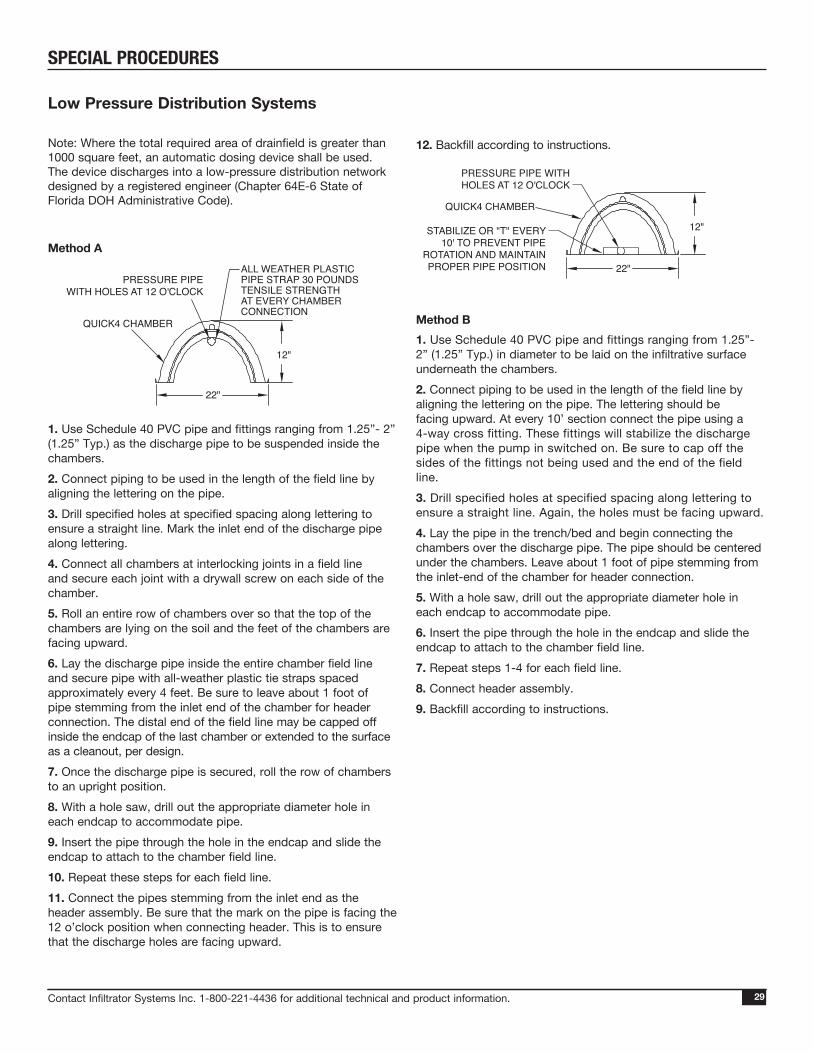
12. Backfill according to instructions.
Method B1. Use Schedule 40 PVC pipe and fittings ranging from 1.25”- 2” (1.25” Typ.) in diameter to be laid on the infiltrative surface underneath the chambers.2. Connect piping to be used in the length of the field line by aligning the lettering on the pipe. The letter ing should be facing upward. At every 10’ section connect the pipe using a 4-way cross fitting. These fittings will stabilize the discharge pipe when the pump in switched on. Be sure to cap off the sides of the fittings not being used and the end of the field line.3. Drill specified holes at specified spacing along lettering to ensure a straight line. Again, the holes must be facing upward.4. Lay the pipe in the trench/bed and begin connecting the chambers over the discharge pipe. The pipe should be centered under the chambers. Leave about 1 foot of pipe stemming from the inlet-end of the chamber for header connection.5. With a hole saw, drill out the appropriate diameter hole in each endcap to accommodate pipe.6. Insert the pipe through the hole in the endcap and slide the endcap to attach to the chamber field line.7. Repeat steps 1-4 for each field line.8. Connect header assembly.9. Backfill according to instructions.
29
Note: Where the total required area of drainfield is greater than 1000 square feet, an automatic dosing device shall be used. The device discharges into a low-pressure distribution network designed by a registered engineer (Chapter 64E-6 State of Florida DOH Administrative Code).
Method A
1. Use Schedule 40 PVC pipe and fittings ranging from 1.25”- 2” (1.25” Typ.) as the discharge pipe to be suspended inside the chambers.2. Connect piping to be used in the length of the field line by aligning the lettering on the pipe.3. Drill specified holes at specified spacing along lettering to ensure a straight line. Mark the inlet end of the discharge pipe along lettering.4. Connect all chambers at interlocking joints in a field line and secure each joint with a drywall screw on each side of the chamber.5. Roll an entire row of chambers over so that the top of the chambers are lying on the soil and the feet of the chambers are facing upward.6. Lay the discharge pipe inside the entire chamber field line and secure pipe with all-weather plastic tie straps spaced approximately every 4 feet. Be sure to leave about 1 foot of pipe stemming from the inlet end of the chamber for header connection. The distal end of the field line may be capped off inside the endcap of the last chamber or extended to the surface as a cleanout, per design.7. Once the discharge pipe is secured, roll the row of chambers to an upright position. 8. With a hole saw, drill out the appropriate diameter hole in each endcap to accommodate pipe.9. Insert the pipe through the hole in the endcap and slide the endcap to attach to the chamber field line.10. Repeat these steps for each field line.11. Connect the pipes stemming from the inlet end as the header assembly. Be sure that the mark on the pipe is facing the 12 o’clock position when connecting header. This is to ensure that the discharge holes are facing upward.
22"
ALL WEATHER PLASTIC PIPE STRAP 30 POUNDS TENSILE STRENGTH AT EVERY CHAMBER CONNECTION
PRESSURE PIPE WITH HOLES AT 12 O'CLOCK
QUICK4 CHAMBER
STABILIZE OR "T" EVERY10' TO PREVENT PIPE
ROTATION AND MAINTAINPROPER PIPE POSITION
PRESSURE PIPE WITH HOLES AT 12 O'CLOCK
Q4EQ36_PRESSDOSE.eps
12"
22"
12"
QUICK4 CHAMBER
22"
ALL WEATHER PLASTIC PIPE STRAP 30 POUNDS TENSILE STRENGTH AT EVERY CHAMBER CONNECTION
PRESSURE PIPE WITH HOLES AT 12 O'CLOCK
QUICK4 CHAMBER
STABILIZE OR "T" EVERY10' TO PREVENT PIPE
ROTATION AND MAINTAINPROPER PIPE POSITION
PRESSURE PIPE WITH HOLES AT 12 O'CLOCK
Q4EQ36_PRESSDOSE.eps
12"
22"
12"
QUICK4 CHAMBER
Low Pressure Distribution Systems
SPECIAL PROCEDURES

Contact Infiltrator Systems Inc. 1-800-221-4436 for additional technical and product information.3030
Low Pressure Distribution with Quick4 Plus EQ36 LP ChambersInstalling the Chambers and Endcaps1. To allow pressure laterals to drain after each dose, drill a hole in the bottom of pipe at end of pressure line. Place the snap-off splash plate or a paving block of equal or larger length and width as splash plate (not to exceed area of endcap) at the bottom of trench to protect the infiltrative surface from erosion.
2. With a hole saw, drill out the appropriate diameter hole to accommodate the pressure lateral pipe.3. Insert pressure lateral pipe into the endcap’s drilled opening and slide it into the manifold pipe. Glue pressure lateral pipe to manifold pipe.4. With pressure lateral pipe through endcap, place back edge of endcap over the inlet end of first chamber. Be sure to line up locking pins on top both chamber and endcap.NOTE: Health departments may require a wet-run pressure check to be done prior to chamber installation when the pipe is laying on the ground. Check with your local health department for the proper procedure.5. (Method A) With the holes pointing up, secure pressure lateral pipe to top of first chamber with a plastic pipe strap at outlet end of the unit. Slide strap up through slot in chamber top, down through other slot, and cinch the two ends around the pipe.6. (Method B) With holes pointing up, stabilize pressure lateral pipe on ground to prevent from moving.7. Lift and place next chamber onto previous one at a 45-degree angle. Line up the chamber end between connector hook and locking pin at top of the first chamber. Lower it to ground to engage the interlocks.
2Drill pressure pipe hole.
1" PRESSURELATERAL (TYP.)
2" PRESSURELATERAL (TYP.)
4Place endcap over inlet end.
5Secure pressure pipe.
8. (Method A) Secure lateral pipe to top of the next chamber once in place. Follow the same method in Step 5.9. Continue interlocking chambers and securing the pipe until the trench is completed.10. Before attaching the final endcap, it may be necessary to remove the tongue of the connector hook on the last chamber with a pair of pliers depending on your pipe diameter.11. Insert the pressure lateral pipe through the hole in the final endcap and slide the endcap toward the last chamber. Lift the endcap over the modified connector hook and push straight down to secure it to the chamber.NOTE: If cleanout extensions are required, use a hole saw to cut a hole in the top of Q4 Plus All-in-One 8 Endcap so the pressure lateral pipe with an elbow can extend to the ground surface. For cleanout access, use the “Installing Optional Inspection Ports” section in the general installation instructions.12. If installing multiple rows of chambers, follow Steps 1-9 to lay next row of chambers parallel to the first. Keep a minimum separation distance between each row of chambers as required by local code.
Advantages of Method A• Pipe and orifice placed closer to the chamber dome offer
improved distribution.• Pipe positioned at the top of the chamber places it well
above effluent.• Plastic pipe hanger easily secures pipe in place.•
Advantages of Method B• Pipe resting on trench bottom allows easy installation and
maintenance.• Stabilizing “T’s” keep pipe level.• System promotes efficient pressure checks.• Pipe resting on trench bottom allows easier inspections if
monitor ports are installed.
11Lateral pipe through endcap.
QUICK4 PLUS STANDARD LP CHAMBER
STABILIZE OR "T" EVERY 10' TO PREVENT PIPE ROTATION AND MAINTAIN PROPER PIPE POSITION
34"
8"
34"
8"
QUICK4 PLUS STANDARD LP CHAMBER
ALL WEATHER PLASTIC PIPE STRAP WITH30 POUNDS TENSILE STRENGTH AT EVERYCHAMBER CONNECTION
PRESSURE PIPE WITH HOLES AT 12 O’CLOCK(MAY BE INSTALLED ON EITHER SIDE)
PRESSURE PIPE WITH HOLES AT 12 O’CLOCK(MAY BE INSTALLED ON EITHER SIDE)
QUICK4 PLUS STANDARD LP CHAMBER
STABILIZE OR "T" EVERY 10' TO PREVENT PIPE ROTATION AND MAINTAIN PROPER PIPE POSITION
34"
8"
34"
8"
QUICK4 PLUS STANDARD LP CHAMBER
ALL WEATHER PLASTIC PIPE STRAP WITH30 POUNDS TENSILE STRENGTH AT EVERYCHAMBER CONNECTION
PRESSURE PIPE WITH HOLES AT 12 O’CLOCK(MAY BE INSTALLED ON EITHER SIDE)
PRESSURE PIPE WITH HOLES AT 12 O’CLOCK(MAY BE INSTALLED ON EITHER SIDE)
Low Pressure Distribution Systems
SPECIAL PROCEDURES

Contact Infiltrator Systems Inc. 1-800-221-4436 for additional technical and product information. 3131
Limited Septic Warranty for Infiltrator Chambers(a) The structural integrity of each Infiltrator chamber and endcap, when installed in accordance with manufacturer’s instructions, is warranted to the original purchaser against defective materials and workmanship for two years from the date of purchase. Should a defect appear within the warranty period, purchaser must inform Infiltrator Systems Inc. of the defect within fifteen (15) days. Infiltrator Systems will supply a replacement chamber and/or endcap. Infiltrator Systems’ liability specifically excludes the cost of removal and/or installation of units.
(b) THE WARRANTY IN SUBPARAGRAPH (a) IS EXCLUSIVE. THERE ARE NO OTHER WARRANTIES WITH RESPECT TO THE CHAMBERS AND Endcaps, INCLUDING NO WARRANTIES OF MERCHANTABILITY OR OF FITNESS FOR A PARTICULAR PURPOSE. THE WARRANTY DOES NOT EXTEND TO INCIDENTAL, CONSEQUENTIAL, SPECIAL, OR INDIRECT DAMAGES. THE COMPANY SHALL NOT BE LIABLE FOR PENALTIES OR LIQUIDATED DAMAGES, INCLUDING LOSS OF PRODUCTION AND PROFITS, LABOR AND MATERIALS, OVERHEAD COSTS, OR OTHER LOSS OR EXPENSE INCURRED BY PURCHASER. SPECIFICALLY EXCLUDED FROM WARRANTY COVERAGE ARE DAMAGE TO THE UNITS DUE TO ORDINARY WEAR AND TEAR, ALTERATION, ACCIDENT, MISUSE, ABUSE, OR NEGLECT OF THE UNITS; THE UNITS BEING SUBJECTED TO STRESSES GREATER THAN THOSE PRESCRIBED IN THE INSTALLATION INSTRUCTIONS; THE PLACEMENT BY PURCHASER OF IMPROPER MATERIALS INTO THE PURCHASER’S SYSTEM; OR ANY OTHER EVENT NOT CAUSED BY THE COMPANY. FURTHERMORE, IN NO EVENT SHALL THE COMPANY BE RESPONSIBLE FOR ANY LOSS OR DAMAGE TO THE PURCHASER, THE UNITS, OR ANY THIRD PARTY RESULTING FROM ITS INSTALLATION OR SHIPMENT. PURCHASER SHALL BE SOLELY RESPONSIBLE FOR ENSURING THAT THE INSTALLATION OF THE SYSTEM IS COMPLETED IN ACCORDANCE WITH ALL APPLICABLE LAWS, CODES, RULES, AND REGULATIONS.
(c) NO REPRESENTATIVE OF THE COMPANY HAS THE AUTHORITY TO CHANGE THIS WARRANTY IN ANY MANNER WHATSOEVER, OR TO EXTEND THIS WARRANTY. NO WARRANTY APPLIES TO ANY PARTY OTHER THAN TO THE ORIGINAL PURCHASER.
(d) All types of chamber systems must be installed in full compliance with the latest version of the product installation requirements. The system must be in full compliance with all aspects of the state regulations and codes.
Performance Warranty for Quick4 Chambers(a) Infiltrator warrants that each Quick4 chamber and MultiPort endcap manufactured by Infiltrator (collectively, the “Units”), when installed and operated in a leachfield of an onsite septic system of a single family residence in accordance with Infiltrator’s instructions, for a period of two (2) years from the date of installation (i) shall be free from defective materials and workmanship; and (ii) shall perform in such a manner to absorb effluent within the design flow rate for the septic system containing the Units, so that there will be no sewage backup into the dwelling or structure which uses the septic system, or visible pooling of effluent around the system. The presence of such sewage backup or such visible pooling shall constitute a “failure” of the system. This Limited Warranty covers new permitted leachfield installations only, and does not cover repairs, extensions or additions to existing leachfields. This Limited Warranty extends only to the original purchasing contractor. For this Limited Warranty to apply, the Units must be installed in accordance with all necessary permits and in accordance with all site conditions required by state and local codes for the installation of gravel and pipe systems, and must be sized according to Infiltrator specifications and state, county and local requirements.
In order to exercise these Limited Warranty rights, the warranty holder must notify Infiltrator in writing at its corporate headquarters in Old Saybrook, Connecticut (address below) within fifteen (15) days of any alleged defect or failure. The notice shall be accompanied by (i) a letter from a state licensed septic tank contractor or Professional engineer detailing cause of failure (ii) a copy of the appropriate permit and design for the septic system; and (iii) proof to Infiltrator’s satisfaction that the septic tank has been pumped at least once every three (3) years since installation. Upon notification of a possible breach of warranty, Infiltrator may undertake an investigation of the circumstances of the possible breach. At its discretion, Infiltrator may perform tests to determine the cause of any breach and may hire a soil scientist or professional engineer or use Infiltrator personnel to evaluate soil conditions and otherwise assist in the investigation.
In the event that Infiltrator determines that there has been a breach of this Limited Warranty due to a failure, Infiltrator will, at its option, either: provide Units as it deems necessary to extend the size of the leachfield and a fee of $12.50 per Unit toward the cost of installation; or provide an equivalent, state-approved solution to cure the breach. Infiltrator will not be responsible for pumps or any other necessary mechanical devices needed to extend or repair the leachfield following a failure, nor shall Infiltrator be liable for the addition of pump systems or underground water diversion systems, or repair or replacement of any landscape or irrigation systems, following a Failure.
In the event of any other breach of this Limited Warranty, Infiltrator will, at its option, either: provide replacement Units for Units determined by Infiltrator to be defective and a fee of $12.50 per Unit toward the cost of installation; or provide an equivalent state-approved solution to cure the breach. Infiltrator’s liability under this Standard Limited Warranty specifically excludes any other cost of removal and/or installation of the Units.
(continued)
Florida Warranties
WARRANTIES

Contact Infiltrator Systems Inc. 1-800-221-4436 for additional technical and product information.32 Contact Infiltrator Systems’ Technical Services Department for assistance at 1-800-221-4436
4 Business Park Road P.O. Box 768 Old Saybrook, CT 06475860-577-7000 • Fax 860-577-70011-800-221-4436www.infiltratorsystems.com
U.S. Patents: 4,759,661; 5,017,041; 5,156,488; 5,336,017; 5,401,116; 5,401,459; 5,511,903; 5,716,163; 5,588,778; 5,839,844 Canadian Patents: 1,329,959; 2,004,564 Other patents pending. Infiltrator, Equalizer, Quick4, and SideWinder are registered trademarks of Infiltrator Systems, Inc. Infiltrator is a registered trademark in France. Infiltrator Systems, Inc. is a registered trademark in Mexico. Contour, MicroLeaching, PolyTuff, ChamberSpacer, MultiPort, PosiLock, QuickCut, QuickPlay, SnapLock and StraightLock are trademarks of Infiltrator Systems, Inc. PolyLok is a trademark of PolyLok, Inc. TUF-TITE is a registered trademark of TUF-TITE, INC. Ultra-Rib is a trademark of IPEX Inc. © 2015 Infiltrator Systems, Inc. All rights reserved. Printed in U.S.A. C33 0315ISI
(b) THIS LIMITED WARRANTY AND THE REMEDIES IN SUBPARAGRAPH (a) ARE EXCLUSIVE. THERE ARE NO OTHER WARRANTIES TO THE ORIGINAL PURCHASING CONTRACTOR WITH RESPECT TO THE UNITS, INCLUDING NO IMPLIED WARRANTIES OF MERCHANTABILITY OR FITNESS FOR A PARTICULAR PURPOSE.
(c) This Limited Warranty shall be void if any part of the chamber system (chamber or endcap) is manufactured by anyone other than Infiltrator. The Limited Warranty does not extend to incidental, consequential, special or indirect damages. Infiltrator shall not be liable for penalties or liquidated damages, including loss of production and profits, labor and materials, overhead costs, or other losses or expenses incurred by the warranty holder or any third party. Specifically excluded from Limited Warranty coverage are damage to the Units due to Acts of God or natural disasters; ordinary wear and tear, alteration, accident, misuse, abuse or neglect of the Units; the Units being subjected to vehicle traffic or other conditions which are not permitted by the installation instructions; failure to maintain the minimum ground cover set forth in the installation instructions; the placement of improper materials into the system containing the Units; failure of the Units or the septic system due to improper siting or improper sizing, improper specified backfill, excessive water usage, improper grease disposal, or improper operation; or any other event not caused by Infiltrator. This Limited Warranty shall be void if the warranty holder fails to comply with all of the terms set forth in this Limited Warranty, including the information required by subparagraph (a).
Furthermore, in no event shall Infiltrator be responsible for any loss or damage to the warranty holder, the Units, or any third party resulting from installation (except as expressly set forth in subparagraph (a) or shipment, or from product liability claims of the warranty holder or any third party. For this Limited Warranty to apply, the Units must be installed in accordance with all site conditions required by state and local codes, all other applicable laws, and Infiltrator’s written instructions.
(d) No representative of Infiltrator has the authority to change this Limited Warranty in any manner whatsoever, or to extend this Limited Warranty. No warranty applies to any party other than the original purchasing contractor.
NOTE: Any chamber systems constructed with less than our minimum sizing requirements will not be covered by any product warranties.
NOTE: In fine and very fine sands, loamy sand and sandy loam soils with low moisture content, it is at the contractor’s discretion to cover the chambers with very fine filter cloth or paper prior to backfilling the system. Standard installation instructions apply.
WARRANTIES
Version March 16, 2015Approved Florida Department of Health, Onsite Sewage ProgramsApril 6, 2015