Embed Size (px)
Citation preview

Design and Implementation of Meter Simulator
for Smart Grid Technology
Hyunjeong Lee, Taein Hwang, and Il-Woo Lee Smart Green Life Research Department, IT Convergence Technology Research Laboratory, ETRI, Korea
Email: {hjlee294, tihwang, ilwoo}@etri.re.kr
Abstract—This paper describes a meter simulator for Smart
Grid technology based on IEC 61968-9. The standard
defines interfaces for meter reading and control and its
scope is the exchange of information between metering
system and other systems within the utility enterprise. There
are some interoperability issues among various kinds of
electric utilities manufactured by different vendors. To test
and certify these utilities, a meter simulator is needed, which
sends meter data periodically and on-demand. Also, it acts
as a metering system to test the functions of disconnection
and reconnection. Using this method, interoperability test of
electric utilities for Smart Grid technology can be easily
performed using the certification system.
Index Terms—meter, simulator, smart grid, IEC 61968-9,
certification, interoperability
I. INTRODUCTION
As the industrialization is progressed, the carbon
dioxide emission becomes the serious issues, because
they cause global warming and climate changes [1].
Therefore, many researches are being carried out for
smart and green technologies to solve them. One of the
goals for energy efficiency is to save resources by
monitoring and analysis of energy consumption [2]. The
Smart Grid technology provides various beneficial effects
by giving smart to the existing power grid, which can
provide new functions such as self-healing, high
reliability, energy management, and real-time pricing [3].
Many technologies related to power and energy topics are
converged for smart grid such as electrical engineering,
information technology, communication, control and
automation. The main contributions of the smart grid are
to reduce CO2 emission and save energy. They are
beneficial to the government in that costs of imported raw
materials used in the production of energy, to the energy
suppliers to minimize the reserved power, and to the
customers to save energy costs by monitoring the real-
time energy use, controlling the appliances, and
managing the scheduling pattern of their home electricity
usage, based on the real-time prices (RTPs) [4].
The international electro technical commission (IEC)
61968-9 is standardized by IEC, which is the global
organization that prepares and publishes International
Standards for all electrical, electronic and related
Manuscript received February 20, 2014; revised June 28, 2014.
technologies. IEC 61968-9 defines interfaces for meter
reading and control for application integration at electric
utilities. Also, it defines the metering system which
performs metrology, supports the distribution and
transmission network, and is represented using the meter
asset class in the common information model (CIM) [5].
The proposed meter simulator (MS) conforms to IEC
61968-9 standard, which describes the exchange of
information among a metering system and other systems
within the utility enterprise. It acts as an integrated
system of an advanced metering infrastructure (AMI)
headend and a meter system. The ability to meter read is
a basic interoperability requirement of utility systems [4].
Also, the MS performs the tasks of the metering system
including the control and reconfiguration, such as service
disconnection and reconnection. Using the proposed
method, the messages among the meter system and
utilities can be easily identified and tested for the
certification system.
II. IEC 61968-9 AND CERTIFICATION SYSTEM
The purpose of the IEC 61968-9 series of standards is
to facilitate inter-application integration as opposed to
intra-application integration. The aim of the intra-
application integration is at programs in the same
application system, usually communicating with each
other using middleware that is embedded in their
underlying runtime environment [4]. And, it tends to be
optimized for close, real-time, synchronous connections
and interactive request and reply or conversation
communication models. Since, these interface standards
are relevant to loosely coupled applications with more
heterogeneity in languages, operating systems, protocols
and management tools, the certification system to test
interoperability is needed to verify the utilities
manufactured by different vendors [6].
The certification system supports for vendors to
enhance their products by interoperability test and
provides certification services and information related to
the standard and technologies for their utilities. The
standard also extends the CIM to support the exchange of
meter data. The CIM is an abstract model that represents
all the major objects in an electric utility enterprise,
which is needed to model the operational aspects of a
utility. Also, the model includes public classes and
attributes for the objects, as well as the relationships
among them [5].
International Journal of Electrical Energy, Vol. 2, No. 3, September 2014
©2014 Engineering and Technology Publishing 254doi: 10.12720/ijoee.2.3.254-257
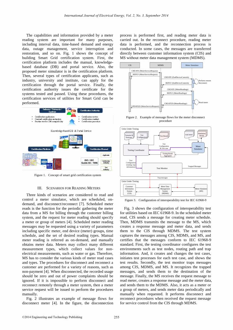
The capabilities and information provided by a meter
reading system are important for many purposes,
including interval data, time-based demand and energy
data, outage management, service interruption and
restoration, and so on. Fig. 1 shows the concept of
building Smart Grid certification system. First, the
certification platform includes the manual, knowledge-
based database (DB) and portal service. Also, the
proposed meter simulator is in the certification platform.
Then, several types of certification applicants, such as
industry, university and institute, can apply for the
certification through the portal service. Finally, the
certification authority issues the certificate for the
systems tested and passed. Using these procedures, the
certification services of utilities for Smart Grid can be
performed.
Figure 1. Concept of smart grid certification system
III. SCENARIOS FOR READING METERS
Three kinds of scenarios are considered to read and
control a meter simulator, which are scheduled, on-
demand, and disconnect/reconnect [7]. Scheduled meter
reads is the function for the periodic gathering the meter
data from a MS for billing through the customer billing
system, and the request for meter reading should specify
a meter or group of meters [4]. Scheduled meter reading
messages may be requested using a variety of parameters
including specific meter, end device (meter) groups, time
schedule, and the set of desired reading types. Manual
meter reading is referred as on-demand, and manually
obtains meter data. Meters may collect many different
measurement types, which collect values for non-
electrical measurements, such as water or gas. Therefore,
MS has to consider the various kinds of meter read cases
and types. The procedures for disconnect and reconnect a
customer are performed for a variety of reasons, such as
non-payment [4]. When disconnected, the recorded usage
should be zero and out of power complaints should be
ignored. If it is impossible to perform disconnect and
reconnect remotely through a meter system, then a meter
service request will be issued to perform the procedures
manually.
Fig. 2 illustrates an example of message flows for
disconnect meter [4]. In the figure, the disconnection
process is performed first, and reading meter data is
carried out. In the reconnect procedure, reading meter
data is performed, and the reconnection process is
conducted. In some cases, the messages are transferred
directly between customer information system (CIS) and
MS without meter data management system (MDMS).
CIS MDMS Meter Simulator
CREATE (MeterServiceRequest)
CREATE (EndDeviceControls)
REPLY (EndDeviceControls)
Perform remote
disconnect
REPLY (MeterServiceRequest)
CREATE (MeterReadings)
REPLY (MeterReadings)
CREATED (MeterReadings)
UPDATED (MeterServiceRequest)
Read meter
Figure 2. Example of message flows for the meter disconnect
procedure
Testsuite &
Testcases
Test
ConfigurationTest Result
Testing Result
Aggregator
Test Monitor
Test
Configuration
(routing, trap
information)
Meter
Simulator
Test
Configuration
& Test case
Trapped Messages
Testing Coordinator
read meterSimulation
Result
Customer
Information
System
(CIS)
Units Under Testing
Meter Data
Management
System
(MDMS)
Meter Simulator
(MS)
Trap messages
Units Under Testing
Figure 3. Configuration of interoperability test for IEC 61968-9
Fig. 3 shows the configuration of interoperability test
for utilities based on IEC 61968-9. In the scheduled meter
read, CIS sends a message for creating meter schedule.
Then, MDMS transmits the message to the MS, which
creates a response message and meter data, and sends
them to the CIS through MDMS. The test system
captures the messages among CIS, MDMS, and MS, and
certifies that the messages conform to IEC 61968-9
standard. First, the testing coordinator configures the test
environments such as test nodes, routing path and trap
information. And, it creates and changes the test cases,
initiates test processes for each test case, and shows the
test results. Secondly, the test monitor traps messages
among CIS, MDMS, and MS. It recognizes the trapped
messages, and sends them to the destination of the
message. Finally, the MS receives the request message to
read meter, creates a response message and the meter data,
and sends them to the MDMS. Also, it acts as a meter or
a group of meters, and sends meter data periodically and
manually when requested. It performs disconnect and
reconnect procedures when received the request message
for service control from the CIS through MDMS.
International Journal of Electrical Energy, Vol. 2, No. 3, September 2014
©2014 Engineering and Technology Publishing 255
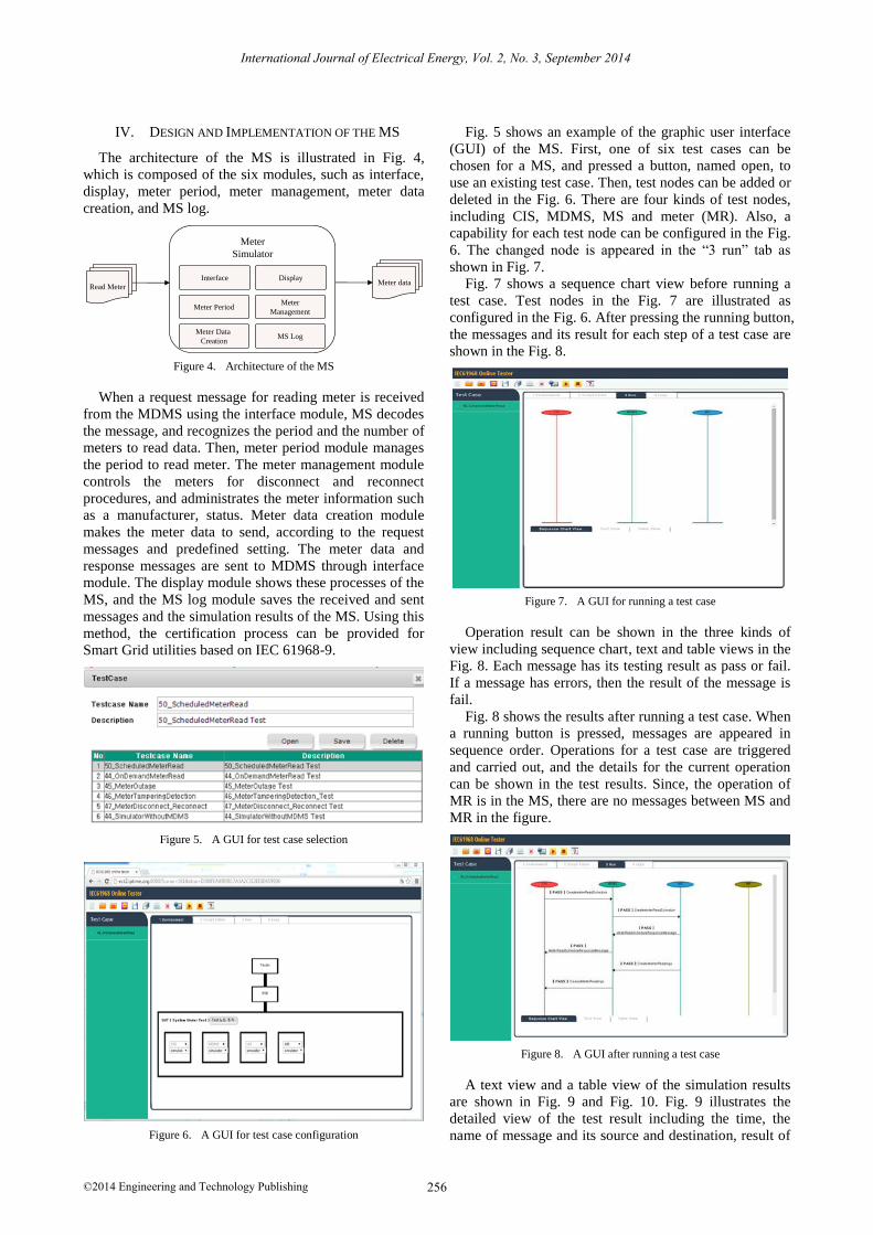
IV. DESIGN AND IMPLEMENTATION OF THE MS
The architecture of the MS is illustrated in Fig. 4,
which is composed of the six modules, such as interface,
display, meter period, meter management, meter data
creation, and MS log.
Read MeterMeter data
Meter
Simulator
Meter PeriodMeter
Management
Meter Data
CreationMS Log
Interface Display
Figure 4. Architecture of the MS
When a request message for reading meter is received
from the MDMS using the interface module, MS decodes
the message, and recognizes the period and the number of
meters to read data. Then, meter period module manages
the period to read meter. The meter management module
controls the meters for disconnect and reconnect
procedures, and administrates the meter information such
as a manufacturer, status. Meter data creation module
makes the meter data to send, according to the request
messages and predefined setting. The meter data and
response messages are sent to MDMS through interface
module. The display module shows these processes of the
MS, and the MS log module saves the received and sent
messages and the simulation results of the MS. Using this
method, the certification process can be provided for
Smart Grid utilities based on IEC 61968-9.
Figure 5. A GUI for test case selection
Figure 6. A GUI for test case configuration
Fig. 5 shows an example of the graphic user interface
(GUI) of the MS. First, one of six test cases can be
chosen for a MS, and pressed a button, named open, to
use an existing test case. Then, test nodes can be added or
deleted in the Fig. 6. There are four kinds of test nodes,
including CIS, MDMS, MS and meter (MR). Also, a
capability for each test node can be configured in the Fig.
6. The changed node is appeared in the “3 run” tab as
shown in Fig. 7.
Fig. 7 shows a sequence chart view before running a
test case. Test nodes in the Fig. 7 are illustrated as
configured in the Fig. 6. After pressing the running button,
the messages and its result for each step of a test case are
shown in the Fig. 8.
Figure 7. A GUI for running a test case
Operation result can be shown in the three kinds of
view including sequence chart, text and table views in the
Fig. 8. Each message has its testing result as pass or fail.
If a message has errors, then the result of the message is
fail.
Fig. 8 shows the results after running a test case. When
a running button is pressed, messages are appeared in
sequence order. Operations for a test case are triggered
and carried out, and the details for the current operation
can be shown in the test results. Since, the operation of
MR is in the MS, there are no messages between MS and
MR in the figure.
Figure 8. A GUI after running a test case
A text view and a table view of the simulation results
are shown in Fig. 9 and Fig. 10. Fig. 9 illustrates the
detailed view of the test result including the time, the
name of message and its source and destination, result of
International Journal of Electrical Energy, Vol. 2, No. 3, September 2014
©2014 Engineering and Technology Publishing 256

the simulation, and the messages. Fig. 10 shows the
summary of the test results. Using these results,
certification processes for each utility for Smart Grid can
be provided. Using the results, the test nodes are decided
to pass or fail of the interoperability test.
Figure 9. A text view of test result
Figure 10. A table view of test result
V. CONCLUSION
In this paper, a meter simulator for Smart Grid
technology based on IEC 61968-9 is described for a
certification system. It is needed to test interoperability
among utility systems from different vendors. Test nodes
can be changed as needed, and test results are shown as
sequence, text and table views. Using the proposed meter
simulator, interoperability test of electric utilities for
Smart Grid technology can be easily performed using the
certification system.
ACKNOWLEDGMENT
This work was supported in part by the R&D program
of Ministry of Trade, Industry and Energy (MOTIE),
Republic of Korea, under Grant of no. 10046464,
Construction of certification system for Smart Grid.
Hyunjeong Lee received her B.S. and M.S.
degrees in computer science from Chungbuk
National University, Korea in 1997 and 1999 respectively. She joined the Electronics and
Telecommunications Research Institute (ETRI) in 1999. She has been engaged in the research
and development of communication protocols,
home network service, context-aware
framework, content transformation technology
and so on. She is currently working as a senior engineer of energy IT technology research
section. Her current research interests include multimedia streaming,
energy optimization, and smart grid technology.
Taein Hwang received his B.E., M.E., and Ph.D. degrees in electrical, electronic and
computer engineering from Sungkyunkwan
University, Korea in 1999, 2001, and 2009, respectively. In 2001, he joined Electronics
and Telecommunications Research Institute (ETRI), where he has been involved in
projects related to networking and control
services. His research interests include home networking and control services, peer-to-peer
networking, IPTV security platform, and smart grid technology.
Il-Woo Lee received B.S. and M.S. degrees in
Computer Engineering from Kyung Hee University, Korea, in 1992 and 1994
respectively and Ph.D degrees in Computer
Engineering from Chungnam National University, Korea, in 2007. He joined
Electronics and Telecommunications Research Institute (ETRI) in 1994 and has
been engaged in the research and development
of ATM, CDMA Switching system, home network system and P2P network, etc. Now,
he is a head of energy IT technology research section and his research interests are green home/building/industry solutions, smart grid
standardization framework, network, and energy-IT technology.
International Journal of Electrical Energy, Vol. 2, No. 3, September 2014
©2014 Engineering and Technology Publishing 257
REFERENCES
[1] H. Lee, W.-K. Park, and I.-W. Lee, “Service level management for energy saving technology,” in Proc. International Smart Grid
Conference and Exhibition 2013, Jeju, Korea, Jul. 2013, pp. 751-754.
[2] H. Lee, W.-K. Park, and I.-W. Lee, “A home energy management
system for energy-efficient smart homes,” in Proc. International Conference on Computational Science and Computational
Intelligence (CSCI), Las Vegas, NV, Mar. 2014, pp. 142-145.[3] S. Kim, “An adaptive smart grid management scheme based on
the coopetition game model,” ETRI Journal, vol. 36, no. 1, pp. 80-
88, Feb. 2014.[4] Z. Zhao, W. C. Lee, Y. Shin, and K.-B. Song, “An optimal power
scheduling method applied in home energy management system based on demand response,” ETRI Journal, vol. 35, no. 4, pp. 677-
686, Aug. 2013.
[5] IEC, “Application integration at electric utilities – System interfaces for distribution management – Part 9: Interfaces for
meter reading and control,” IEC 61968-9, 2009.[6] IEC, “Energy management system application program interface
(EMS-API) – Part 301: Common information model (CIM) base,”
IEC 61970-301, 2007.[7] EPRI, “Common information model scheduled meter read
interoperability test procedure,” 2011 Technical Report, 2011.