Embed Size (px)
Citation preview
DESIGN AND IMPLEMENTATION OF A REAL TIME GPS NETWORK FOR THE METROPOLITAN WATER DISTRICT OF SOUTHERN
CALIFORNIA
Cecilia Whitaker Metropolitan Water District of Southern California, USA
Yehuda Bock1 and Glen Offield
Scripps Institution of Oceanography, USA ABSTRACT The Metropolitan Water District (MWD) of Southern California, in collaboration with the Scripps Orbit and Permanent Array Center (SOPAC) at University of California, San Diego, has undertaken the design and implementation of a 30-station real time GPS network (RTN). MWDRTN is currently in the final field installation stage (first phase) and the initial field-testing phase. The network is designed for use by MWD surveyors and engineers for construction projects, pipeline locations, mapping, GIS studies and projects, deformation studies (including an existing dam deformation system at Diamond Valley Lake) and various other positional needs within our service area (5200 square miles of Southern California). MWDRTN utilizes continuous GPS (CGPS) sites that were installed (1995 to 2002) by the Southern California Integrated GPS Network for seismic and crustal motion research and several newly installed (2004) sites from Earthscope’s Plate Boundary Observatory project. Some of the SCIGN stations were previously converted to real-time operations, with the raw 1 Hz data recorded at SOPAC for earthquake monitoring. Each of the approximately 20 CGPS sites chosen for the network (scattered across both Riverside and San Bernardino Counties) are equipped with a wireless LAN (WiLAN) radio, a data buffer and appropriate antenna, cables, etc. The sites communicate with the MWD enterprise communications backbone via the WiLAN radios on an IP-based system. The data are collected at a main server using Geodetics, Inc’s RTD (Real Time Dynamics) software, a server/client application providing users with precise instantaneous network positioning through TCP/IP (cell phone modems). The primary objective of installing this network is the increase in labor efficiency (and therefore cost savings) that we expect to achieve. MWD has a large workload of projects, undertaken by both employees and contractors. MWD will gain from the ability of both work forces to utilize the RTN for conjoint projects. Productivity should increase by utilizing one-person crews and by having access to instantaneous turn around for construction projects and emergency repairs. Using RTD’s network-based approach we will also achieve better accuracy and reliability than using a standard RTK-based solution, by allowing users access to instantaneous multiply determined position solutions. This paper will describe the network design, first phase of installation, and initial results. PRIMARY CONTACT Cecilia Whitaker, PLS Metropolitan Water District of Southern California, USA 700 Moreno Avenue, La Verne, California 91750 Ph: 909-392-2591, Fax: 909-392-2464; [email protected]
1 Also at Geodetics, Inc., San Diego, California
3rd IAG / 12th FIG Symposium, Baden, May 22-24, 2006____________________________________________________________________
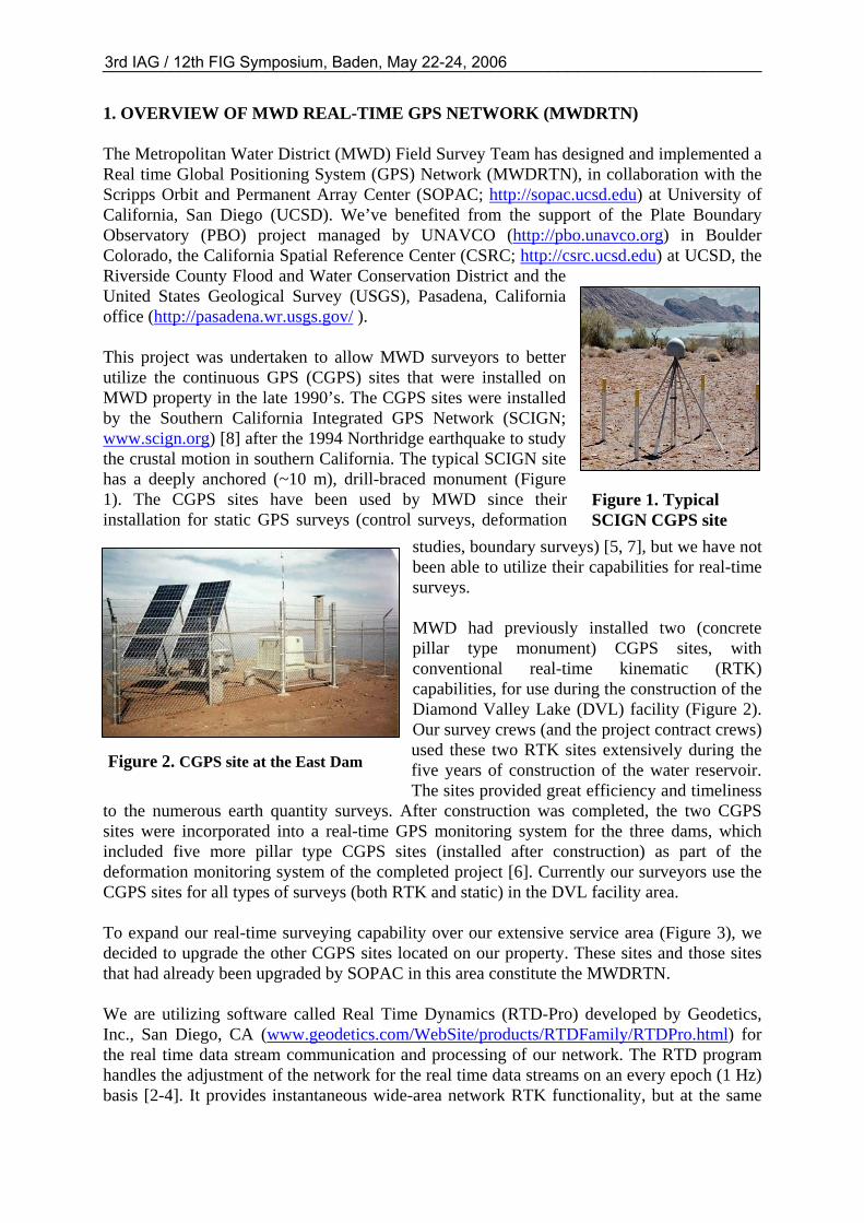
Figure 2. CGPS site at the East Dam
Figure 1. Typical SCIGN CGPS site
1. OVERVIEW OF MWD REAL-TIME GPS NETWORK (MWDRTN) The Metropolitan Water District (MWD) Field Survey Team has designed and implemented a Real time Global Positioning System (GPS) Network (MWDRTN), in collaboration with the Scripps Orbit and Permanent Array Center (SOPAC; http://sopac.ucsd.edu) at University of California, San Diego (UCSD). We’ve benefited from the support of the Plate Boundary Observatory (PBO) project managed by UNAVCO (http://pbo.unavco.org) in Boulder Colorado, the California Spatial Reference Center (CSRC; http://csrc.ucsd.edu) at UCSD, the Riverside County Flood and Water Conservation District and the United States Geological Survey (USGS), Pasadena, California office (http://pasadena.wr.usgs.gov/ ). This project was undertaken to allow MWD surveyors to better utilize the continuous GPS (CGPS) sites that were installed on MWD property in the late 1990’s. The CGPS sites were installed by the Southern California Integrated GPS Network (SCIGN; www.scign.org) [8] after the 1994 Northridge earthquake to study the crustal motion in southern California. The typical SCIGN site has a deeply anchored (~10 m), drill-braced monument (Figure 1). The CGPS sites have been used by MWD since their installation for static GPS surveys (control surveys, deformation
studies, boundary surveys) [5, 7], but we have not been able to utilize their capabilities for real-time surveys. MWD had previously installed two (concrete pillar type monument) CGPS sites, with conventional real-time kinematic (RTK) capabilities, for use during the construction of the Diamond Valley Lake (DVL) facility (Figure 2). Our survey crews (and the project contract crews) used these two RTK sites extensively during the five years of construction of the water reservoir. The sites provided great efficiency and timeliness
to the numerous earth quantity surveys. After construction was completed, the two CGPS sites were incorporated into a real-time GPS monitoring system for the three dams, which included five more pillar type CGPS sites (installed after construction) as part of the deformation monitoring system of the completed project [6]. Currently our surveyors use the CGPS sites for all types of surveys (both RTK and static) in the DVL facility area. To expand our real-time surveying capability over our extensive service area (Figure 3), we decided to upgrade the other CGPS sites located on our property. These sites and those sites that had already been upgraded by SOPAC in this area constitute the MWDRTN. We are utilizing software called Real Time Dynamics (RTD-Pro) developed by Geodetics, Inc., San Diego, CA (www.geodetics.com/WebSite/products/RTDFamily/RTDPro.html) for the real time data stream communication and processing of our network. The RTD program handles the adjustment of the network for the real time data streams on an every epoch (1 Hz) basis [2-4]. It provides instantaneous wide-area network RTK functionality, but at the same
3rd IAG / 12th FIG Symposium, Baden, May 22-24, 2006____________________________________________________________________
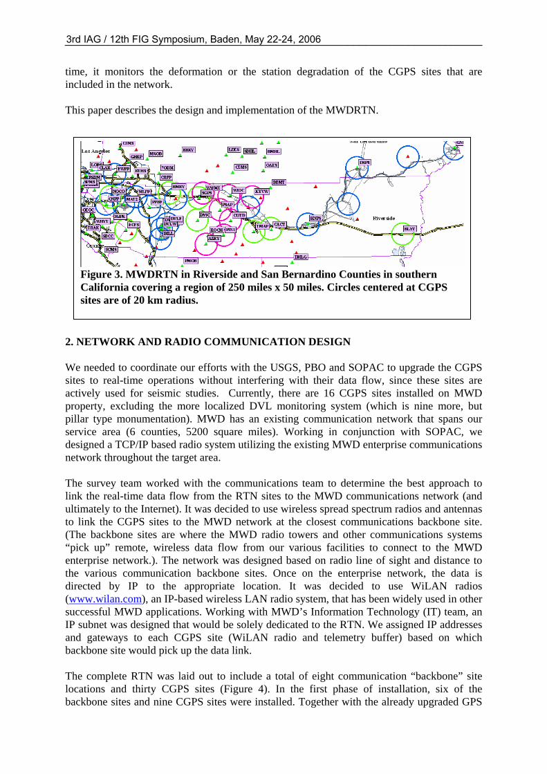
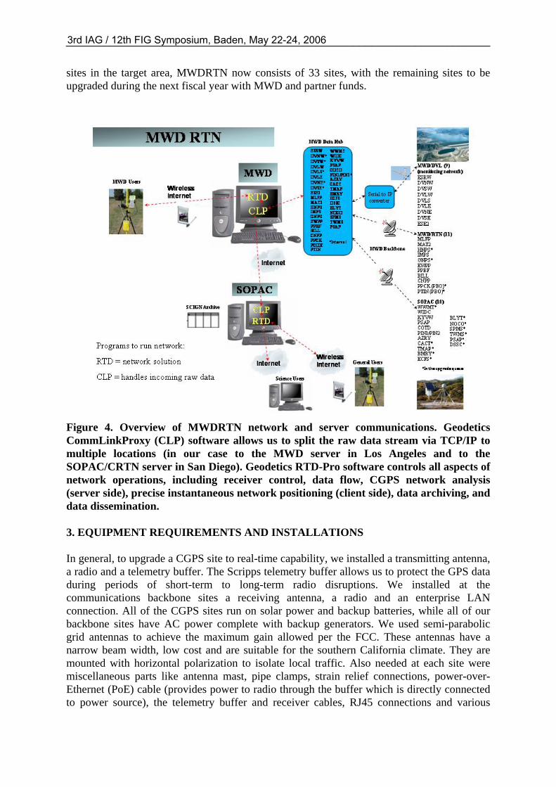
Figure 3. MWDRTN in Riverside and San Bernardino Counties in southern California covering a region of 250 miles x 50 miles. Circles centered at CGPS sites are of 20 km radius.
time, it monitors the deformation or the station degradation of the CGPS sites that are included in the network. This paper describes the design and implementation of the MWDRTN.
2. NETWORK AND RADIO COMMUNICATION DESIGN We needed to coordinate our efforts with the USGS, PBO and SOPAC to upgrade the CGPS sites to real-time operations without interfering with their data flow, since these sites are actively used for seismic studies. Currently, there are 16 CGPS sites installed on MWD property, excluding the more localized DVL monitoring system (which is nine more, but pillar type monumentation). MWD has an existing communication network that spans our service area (6 counties, 5200 square miles). Working in conjunction with SOPAC, we designed a TCP/IP based radio system utilizing the existing MWD enterprise communications network throughout the target area. The survey team worked with the communications team to determine the best approach to link the real-time data flow from the RTN sites to the MWD communications network (and ultimately to the Internet). It was decided to use wireless spread spectrum radios and antennas to link the CGPS sites to the MWD network at the closest communications backbone site. (The backbone sites are where the MWD radio towers and other communications systems “pick up” remote, wireless data flow from our various facilities to connect to the MWD enterprise network.). The network was designed based on radio line of sight and distance to the various communication backbone sites. Once on the enterprise network, the data is directed by IP to the appropriate location. It was decided to use WiLAN radios (www.wilan.com), an IP-based wireless LAN radio system, that has been widely used in other successful MWD applications. Working with MWD’s Information Technology (IT) team, an IP subnet was designed that would be solely dedicated to the RTN. We assigned IP addresses and gateways to each CGPS site (WiLAN radio and telemetry buffer) based on which backbone site would pick up the data link. The complete RTN was laid out to include a total of eight communication “backbone” site locations and thirty CGPS sites (Figure 4). In the first phase of installation, six of the backbone sites and nine CGPS sites were installed. Together with the already upgraded GPS
3rd IAG / 12th FIG Symposium, Baden, May 22-24, 2006____________________________________________________________________
sites in the target area, MWDRTN now consists of 33 sites, with the remaining sites to be upgraded during the next fiscal year with MWD and partner funds.
Figure 4. Overview of MWDRTN network and server communications. Geodetics CommLinkProxy (CLP) software allows us to split the raw data stream via TCP/IP to multiple locations (in our case to the MWD server in Los Angeles and to the SOPAC/CRTN server in San Diego). Geodetics RTD-Pro software controls all aspects of network operations, including receiver control, data flow, CGPS network analysis (server side), precise instantaneous network positioning (client side), data archiving, and data dissemination. 3. EQUIPMENT REQUIREMENTS AND INSTALLATIONS In general, to upgrade a CGPS site to real-time capability, we installed a transmitting antenna, a radio and a telemetry buffer. The Scripps telemetry buffer allows us to protect the GPS data during periods of short-term to long-term radio disruptions. We installed at the communications backbone sites a receiving antenna, a radio and an enterprise LAN connection. All of the CGPS sites run on solar power and backup batteries, while all of our backbone sites have AC power complete with backup generators. We used semi-parabolic grid antennas to achieve the maximum gain allowed per the FCC. These antennas have a narrow beam width, low cost and are suitable for the southern California climate. They are mounted with horizontal polarization to isolate local traffic. Also needed at each site were miscellaneous parts like antenna mast, pipe clamps, strain relief connections, power-over-Ethernet (PoE) cable (provides power to radio through the buffer which is directly connected to power source), the telemetry buffer and receiver cables, RJ45 connections and various
3rd IAG / 12th FIG Symposium, Baden, May 22-24, 2006____________________________________________________________________
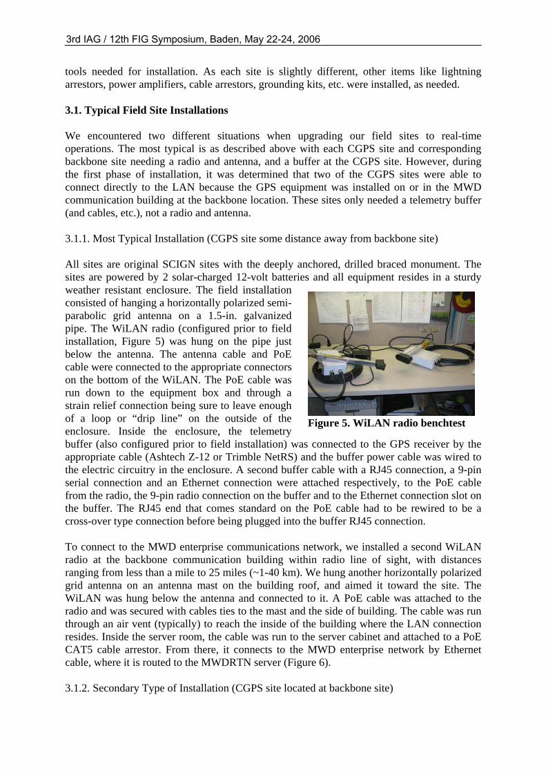
Figure 5. WiLAN radio benchtest
tools needed for installation. As each site is slightly different, other items like lightning arrestors, power amplifiers, cable arrestors, grounding kits, etc. were installed, as needed. 3.1. Typical Field Site Installations We encountered two different situations when upgrading our field sites to real-time operations. The most typical is as described above with each CGPS site and corresponding backbone site needing a radio and antenna, and a buffer at the CGPS site. However, during the first phase of installation, it was determined that two of the CGPS sites were able to connect directly to the LAN because the GPS equipment was installed on or in the MWD communication building at the backbone location. These sites only needed a telemetry buffer (and cables, etc.), not a radio and antenna. 3.1.1. Most Typical Installation (CGPS site some distance away from backbone site) All sites are original SCIGN sites with the deeply anchored, drilled braced monument. The sites are powered by 2 solar-charged 12-volt batteries and all equipment resides in a sturdy weather resistant enclosure. The field installation consisted of hanging a horizontally polarized semi-parabolic grid antenna on a 1.5-in. galvanized pipe. The WiLAN radio (configured prior to field installation, Figure 5) was hung on the pipe just below the antenna. The antenna cable and PoE cable were connected to the appropriate connectors on the bottom of the WiLAN. The PoE cable was run down to the equipment box and through a strain relief connection being sure to leave enough of a loop or “drip line” on the outside of the enclosure. Inside the enclosure, the telemetry buffer (also configured prior to field installation) was connected to the GPS receiver by the appropriate cable (Ashtech Z-12 or Trimble NetRS) and the buffer power cable was wired to the electric circuitry in the enclosure. A second buffer cable with a RJ45 connection, a 9-pin serial connection and an Ethernet connection were attached respectively, to the PoE cable from the radio, the 9-pin radio connection on the buffer and to the Ethernet connection slot on the buffer. The RJ45 end that comes standard on the PoE cable had to be rewired to be a cross-over type connection before being plugged into the buffer RJ45 connection. To connect to the MWD enterprise communications network, we installed a second WiLAN radio at the backbone communication building within radio line of sight, with distances ranging from less than a mile to 25 miles (~1-40 km). We hung another horizontally polarized grid antenna on an antenna mast on the building roof, and aimed it toward the site. The WiLAN was hung below the antenna and connected to it. A PoE cable was attached to the radio and was secured with cables ties to the mast and the side of building. The cable was run through an air vent (typically) to reach the inside of the building where the LAN connection resides. Inside the server room, the cable was run to the server cabinet and attached to a PoE CAT5 cable arrestor. From there, it connects to the MWD enterprise network by Ethernet cable, where it is routed to the MWDRTN server (Figure 6). 3.1.2. Secondary Type of Installation (CGPS site located at backbone site)
3rd IAG / 12th FIG Symposium, Baden, May 22-24, 2006____________________________________________________________________
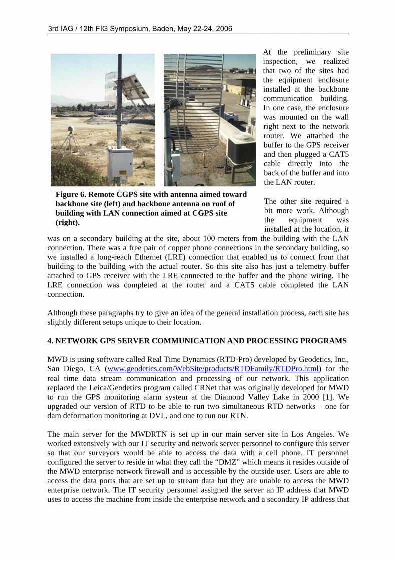
Figure 6. Remote CGPS site with antenna aimed toward backbone site (left) and backbone antenna on roof of building with LAN connection aimed at CGPS site (right).
At the preliminary site inspection, we realized that two of the sites had the equipment enclosure installed at the backbone communication building. In one case, the enclosure was mounted on the wall right next to the network router. We attached the buffer to the GPS receiver and then plugged a CAT5 cable directly into the back of the buffer and into the LAN router. The other site required a bit more work. Although the equipment was installed at the location, it
was on a secondary building at the site, about 100 meters from the building with the LAN connection. There was a free pair of copper phone connections in the secondary building, so we installed a long-reach Ethernet (LRE) connection that enabled us to connect from that building to the building with the actual router. So this site also has just a telemetry buffer attached to GPS receiver with the LRE connected to the buffer and the phone wiring. The LRE connection was completed at the router and a CAT5 cable completed the LAN connection. Although these paragraphs try to give an idea of the general installation process, each site has slightly different setups unique to their location. 4. NETWORK GPS SERVER COMMUNICATION AND PROCESSING PROGRAMS MWD is using software called Real Time Dynamics (RTD-Pro) developed by Geodetics, Inc., San Diego, CA (www.geodetics.com/WebSite/products/RTDFamily/RTDPro.html) for the real time data stream communication and processing of our network. This application replaced the Leica/Geodetics program called CRNet that was originally developed for MWD to run the GPS monitoring alarm system at the Diamond Valley Lake in 2000 [1]. We upgraded our version of RTD to be able to run two simultaneous RTD networks – one for dam deformation monitoring at DVL, and one to run our RTN. The main server for the MWDRTN is set up in our main server site in Los Angeles. We worked extensively with our IT security and network server personnel to configure this server so that our surveyors would be able to access the data with a cell phone. IT personnel configured the server to reside in what they call the “DMZ” which means it resides outside of the MWD enterprise network firewall and is accessible by the outside user. Users are able to access the data ports that are set up to stream data but they are unable to access the MWD enterprise network. The IT security personnel assigned the server an IP address that MWD uses to access the machine from inside the enterprise network and a secondary IP address that
3rd IAG / 12th FIG Symposium, Baden, May 22-24, 2006____________________________________________________________________
the public is able to access. This server runs both the DVL monitoring network and the MWDRTN. The RTD software suite [2] includes an executable called CommLinkProxy that handles the data streaming (Figure 4). The MWDRTN server uses CommLinkProxy to direct the data flow so each different CGPS data stream is assigned a server port that receives the incoming data stream and a second port where the outgoing data can be received by MWD’s RTD program. The outgoing raw data stream is also available to SOPAC, who archives the data and makes them available as part of the California Real Time Network. The CRTN broadcasts to all CGPS sites upgraded to real time in California (http://sopac.ucsd.edu/projects/realtime). The data can be broadcast in WGS84, ITRF, NAD83, or any other datum. Since the MWDRTN is for use by our surveyors, we are broadcasting NAD83 values in the 1991.35 epoch of our state-wide High Precision Geodetic Network (HPGN). This is because all of our facilities were mapped using that epoch. The same data, served to the public by Scripps, are broadcast in the NAD83 2004.0 epoch HPGN (the current HPGN epoch) from one designated set of server ports and in ITRF2000 from another set of server ports for scientific users. 5. DISCUSSION The MWD service area stretches from the Colorado River (California/Arizona border) west to the Pacific Ocean. The San Andreas Fault (among many others) dissects our service area. The challenge MWD faces is trying to establish a network over its entire infrastructure when part of it is moving, however slowly, away from the other part. We need the horizontal positions for all infrastructure relative to the same geodetic epoch for determining water flow, redesigns, repairs, new construction, etc. Trying to keep all facilities (service-district-wide) accurately positioned relative to each other is a challenge that we are slowly losing, in a static sense. This scenario is further complicated by large earthquakes within our region such as occurred in 1992 and 1999, which caused up to several meters of horizontal deformation near the earthquake epicentres. Historically, we have completed field surveys that incorporated 1991.35 epoch ground control. As we started utilizing CGPS sites with our static surveys we included 1991.35 ground control, so that we could establish 1991.35 values on the CGPS sites. As time passed survey accuracy deteriorated, since the velocities of the two types of control sites (conventional geodetic monuments and CGPS) were not being taken into account. As more and more data from the 300+ CGPS sites poured into SOPAC, they were able to develop a velocity model based utility of the CGPS sites that allowed a user to request any epoch date they required for a CGPS site. SOPAC’s SECTOR utility (http://csrc.ucsd.edu/cgi-bin/sector.cgi) allows the user to transform a current survey to a past epoch date based on real (observed) velocities, greatly improving our post-processed results. As far as RTK surveying goes, our main concern has always been the issue of radial surveying. It is far too easy to get an “answer” and pass it on to the contactor who is breathing down your neck. The RTD-Pro software helps us address both of these concerns. As shown in [3-4], the RTD software handles the issues that come from trying to establish fixed positions on a differentially moving region of land. The RTD program handles the adjustment of the network for the real time data streams on an every epoch (1 Hz) basis [2-4]. It provides instantaneous wide-area network RTK functionality, but at the same time it monitors the deformation or the station degradation of the CGPS sites that are included in the network. The
3rd IAG / 12th FIG Symposium, Baden, May 22-24, 2006____________________________________________________________________
program takes into account the velocities and past coseismic deformations of all the CGPS sites in the network and adjusts the network every epoch. This is all done in the ITRF2000 reference frame utilizing ultra-rapid orbits from IGS (http://igscb.jpl.nasa.gov). The software that resides in the “rover”/data collector (RTD Rover; www.geodetics.com/WebSite/products/RTDFamily/RTDRoverSpecs.html) works in conjunction with a Carlson Software program (SurvCE; www.carlsonsw.com/PL_survCE.htm) to transform the ITRF2000 positions to “on-the-fly” NAD83 positions for the field surveyor. (Due to delays in the manufacturing process, we have not yet received the Carlson equipment at this writing. A future paper will address the field-testing of the rover software and initial results.) RTD-Pro also offers a network RTK rover mode called Smart Client, in addition to standard RTK formats [4]. The Smart Client allows the field surveyor to get a rigorous, adjusted position from two or three CGPS sites in the network (usually three closest). This adjusted position is based on the whole network, taking into account site velocities, coseismic displacements, and tropospheric models. The field surveyor is now able to take as many epoch measurements as needed, to be assured that the final averaged position is accurate (within RTK specifications of equipment) in the field. We feel this mode of RTK surveying will allow us to broaden our use of RTK survey methods. 6. SUMMARY The goal of this paper was to describe some of the details and reasoning behind the RTK network design that MWD has chosen. This is a truly multi-disciplinary project with aspects of surveying, geodesy, telemetry and various types of communication networks. The first phase is mostly complete with nine field sites installed and two others pending completion. With the existing upgraded SCIGN sites, there are now 33 real-time CGPS in our target area. Each field site offers it own challenges with radio line of sight issues, power, etc, but these can usually be resolved. The RTN server is set up at our main server site in the Los Angeles headquarters. The IT personnel have configured the server to be very secure and user friendly. The RTD program on the server is configured for MWD use in the NAD83 1991.35 epoch date. The raw and RTK data is currently streaming to Scripps who archives it and broadcasts to users in the NAD83 2004.0 epoch date and in ITRF2000, as part of the CRTN project We plan to report on the use of this system in field situations in a future paper. The biggest hurdle, if you will, of a project of this sort are the IT issues in a large enterprise communication network. The authors would recommend inclusion of IT personnel at the start if you plan to tackle a network such as described herein. MWD is fortunate to have an IT group that includes expertise in server and network communications, information security, telecommunications, radio and microwave communications and the patience to put up with surveyors who are working outside their area of expertise. Without the MWD IT team’s expertise, this project would not have come to fruition and we hereby acknowledge their gracious assistance. The primary author would also like to acknowledge the tremendous amount of training, support and assistance offered by Scripps personnel.
3rd IAG / 12th FIG Symposium, Baden, May 22-24, 2006____________________________________________________________________
REFERENCES [1] Bock, Yehuda, Paul J. de Jonge, David Honcik, Michael Bevis, Lydia Bock and Steve
Wilson (2001). “Epoch-by-Epoch™ Positioning Applied to Dam Deformation Monitoring at Diamond Valley Lake, Southern California.” Proceedings of Commission 6, of the International Federation of Surveyors, Deformation Working Group, 10th International Symposium on Deformation Measurements, Orange, California, USA, March 19 – 22, 2001, pp.78 -87. http://www.fig.net/com6_orange/pdf/Session%20III_Paper%201.pdf
[2] Bock, Yehuda, Paul J. de Jonge, David Honcik and Jeff Fayman (2003). “Wireless
Instantaneous Network RTK: Positioning and Navigation.” Proceedings of the Institute of Navigation (ION), ION GPS 2003. Portland, Oregon, September 9-12, 2003, pp. 1397-1405.
[3] Bock, Yehuda (2004). “Instantaneous Network RTK Positioning in Areas of Active
Deformation.” Geodetics, Inc., La Jolla, CA. http://www.geodetics.com/WebSite/papers/YBock_ION2004.pdf
[4] Bock, Yehuda, Jeff Fayman, David Honcik, Paul de Jonge and Lydia Bock, Precise
Instantaneous Network Positioning: Inverse Network RTK and Position Server, Proceedings of the Institute of Navigation (ION), ION GNSS 2005, Long Beach, California, September, 2005.
[5] Duffy, Michael A. and Cecilia Whitaker (1999). "Deformation Monitoring Scheme using
Static GPS and Continuous Operating Reference Stations (CORS) in California." Proceedings of the Institute of Navigation (ION), ION GPS '99. Nashville, Tennessee, September 14-17, 1999, pp. 63 -70.
[6] Duffy, Michael A., Chris Hill, Cecilia Whitaker, Adam Chrzanowski, James Lutes and
Geoffrey Bastin (2001). "An Automated and Integrated Monitoring Program for Diamond Valley Lake in California." Proceedings of Commission 6, of the International Federation of Surveyors, Deformation Working Group, 10th International Symposium on Deformation Measurements, Orange, California, USA, March 19 – 22, 2001, pp. K-1 to K-23. http://www.fig.net/figtree/com6_orange/pdf/Keynote Technical Presentation.pdf
[7] Duffy, Michael A. and Cecilia Whitaker (2003). "Utilization of Continuous Operating
Reference Stations (CORS) in Southern California for Deformation Monitoring." Proceedings of Commission 6, of the International Federation of Surveyors, Deformation Working Group, 11th International Symposium on Deformation Measurements, Santorini, Greece, May 25 – 28, 2003, pp 16 - 22. http://www.fig.net/figtree/commission6/santorini/A-TECTONOPHYSICS%20&%20SEISMOLOGY/A1.pdf
[8] Hudnut, Kenneth W., Yehuda Bock, John E. Galetzka, Frank H. Webb, and William H.
Young (2001). "The Southern California Integrated GPS Network (SCIGN)." Proceedings of Commission 6, of the International Federation of Surveyors, Deformation Working Group, 10th International Symposium on Deformation Measurements, Orange, California, USA, pp. 129 to 148. http://www.fig.net/com6_orange/pdf/Session%20IV_Paper%201.pdf
3rd IAG / 12th FIG Symposium, Baden, May 22-24, 2006____________________________________________________________________