Embed Size (px)
Citation preview
Design and flight test of a civil unmanned aerial vehicle for
maritime patrol: the use of 3D-printed structural
components.
Mario Ferraro, Andrew Lock, James P. Scanlan, Andy J. Keane
Computational Engineering Design Group
Southampton Boldrewood Innovation Campus
University of Southampton
SO16 7QF
UK
This paper describes the design of the “Spotter” unmanned aerial vehicle, developed by the University of
Southampton as part of the 2SEAS-3i European Interreg project. Spotter is a twin engine, 4m wing span,
fixed-wing aircraft which has been designed to perform long-endurance, all-weather patrol missions in
coastal and maritime environments. Reliability and safety have been among the strongest design drivers
of this project; Spotter is able to survive the failure of one engine and of any single control surface. A
modular approach has been adopted for the payload unit in order to allow the users to rapidly
interchange the sensors required to perform different missions.
One of the most innovative aspects of Spotter is the extensive use of the Selective Laser Sintering (SLS)
technology (also known as 3D printing) for many of the components of its airframe. By eliminating
tooling and manual labour, the 3D printing technology allows the designer to produce complex and high-
performance structures at a relatively low cost and within hours of the completion of the design.
Spotter and a sub-20kg version, codenamed 2SEAS-20, have undergone an extensive flight test campaign,
totalling hundreds of autonomous flights (including autonomous take-off and landings) and many flight
hours. This has provided the opportunity to test the reliability and robustness of the system and to gain a
deeper insight into the opportunities and problems presented by the use of 3D printed structures for large
airframe components.
Nomenclature
2SEAS-3i Integrated coastal zone management via Increased situational awareness through Innovations
on unmanned aircraft systems
CAD Computer-Aided Design
SULSA Southampton University Laser Sintered Aircraft
UAV Unmanned Aerial Vehicle
1 Introduction
The 2SEAS-3i is a European Interreg project that aims to “make the public, government and industry aware of
Unmanned Aircraft Vehicles, their potential applications on gathering data and creating a safer and more
sustainable area; their research challenges and the possibilities for SMEs to develop related products and
services”1. The project has been undertaken by a consortium of partners including universities, specialist
organizations, public sector entities and commercial companies based in three different countries (UK,
Netherlands and France). One of the goals of the 2SEAS-3i project has been to develop a UAV system that
would perform missions in maritime safety scenarios. The role of the University of Southampton has been to
1 http://www.2seas-uav.com/

develop an aircraft capable of meeting the end-users requirements – in this case police forces and port
authorities – while keeping the system cost as low as possible. The system development has been strongly
influenced by the time constraint; the overall design, building and flight test campaign has been realized within
the two years life-span of the project. In order to meet these ambitious goals, the airframe has been designed
with rapid manufacturing in mind. In particular there has been an extensive use of 3D printed components.
3D printing refers to a number of additive manufacturing techniques. Additive manufacturing entails the
creation of a three-dimensional object from a computer-aided design (CAD) representation through the
deposition of material. 3D printing is also referred as rapid prototyping as the technology was initially
developed to help engineers and designers to better visualize the parts they were working on. However, the use
of 3D printing to produce final parts is becoming increasingly common due to improvements in the technology
and reduction of costs [1, 2].
There are a number of different 3D-printing techniques, but all of them share the same workflow. First, the
object CAD model is divided into thin “slices” (layers); the initial layer is created by joining together particles
of a raw material; when this is complete, a second layer is built on the first and the process repeated until the
object is complete. The various additive manufacturing techniques differ for the material used, the process used
to bond together the particles of material and the initial state of the raw material (typically liquid or powder).
Each of these techniques presents its own advantages and limitations which have been extensively studied in
previous works [3–7]. This work will focus on the use of Selective Laser Sintering (SLS) plastic components for
aerospace applications.
Recently, aircraft designers have started to consider 3D printing as a competitive manufacturing option for at
least some parts of the final product [8–10], particularly in the world of small unmanned aircraft [11, 12]. The
University of Southampton has been pioneering this trend by realising and flying the world’s first entirely 3D-
printed aircraft (codenamed SULSA) [13] and with the DECODE project [14–16]. Spotter represents the latest
continuation of this work on a larger scale; the fuselage, fuel tank and most of the high-complexity parts of the
wing and empennage have been produced in SLS nylon.
This paper will briefly present the main characteristics of “Spotter”, focus on the use of 3D-printed structural
component and briefly present the results of the flight test campaign.
2 Spotter design characteristics
2.1 System requirements
The 2SEAS-3i project initiated with a meeting between technical experts in the field of unmanned systems and
potential end-users. The latter were represented by the Kent Police (UK), the Port of Rotterdam and the Dutch
National Police (NL). The goal of this initial phase was for the system developers to try to understand the
customer needs and translate them into technical requirements; and for the end-users to understand the potential
of the UAVs and propose operational scenarios. The focus was on maritime missions because of the reduced
risks compared to the operation over densely populated European land. The partners identified a number of
typical missions that would greatly benefit from the use of an unmanned system, both in terms of cost reduction
and enhanced effectiveness over current operations. These included environmental monitoring and prevention of
pollution at sea, identification of boats before they enter the port, monitoring and protecting off-shore wind
farms, emergency response for accidents at sea, shore activity monitoring, and other tasks.
The team identified the following important system requirements and desirable characteristics:
1- Safety. The end-users were very concerned by the risk of an aircraft crashing in proximity of people or
infrastructure. Particularly, accidents in large commercial ports could result in catastrophic
consequences due to the presence of dangerous chemicals. The missions performed over the sea and far
from populated areas were considered less hazardous. However, even in this case, there was a clear
desire for a system that could reliably bring back the expensive sensors used to perform the mission.

Finally, the aircraft had to demonstrate a high safety standard in order to obtain the permission to fly
from the civil aviation authority.
2- Low-cost. The main argument for the adoption of an unmanned system by the police forces and port
authorities is the opportunity to cut the cost of their operations while retaining or enhancing their
capabilities. A study describing the cost-benefit analysis of the use of UAV in the 2SEAS-3i
operational scenarios has been presented in a different publication [17].
3- All-weather. In order to operate in the harsh maritime environment, the aircraft has to be able to fly in
strong winds and be resistant to rain and salt water.
4- Long endurance and range. A minimum endurance of 4 hours and an operative range of 10 km from
the shoreline were considered satisfactory.
5- Versatility. The ability to perform a range of different missions requiring different payloads (cameras,
infrared cameras, chemical sensors, etc.) was identified as highly desirable.
6- Minimal infrastructure requirement. The system (including ground station) should be self-contained
and capable of deployment from small areas.
7- Ease of handling. The system should be quick to deploy and straightforward to operate and maintain.
8- Short development time. Able to develop and test a number of prototypes within the two-year project
duration.
a
b
Figure 1 – Three views of 2SEAS-20 (a) and Spotter (b)
2.2 System description
The design effort led to the development of a fixed-wing unmanned aircraft. It has been developed in two
versions: the first prototype, codenamed 2SEAS-20, was designed to have an empty weight (i.e. the aircraft mass
with no fuel or payload on board) below 20kg and hence be classified as a Small Unmanned Aircraft (SUA) by
the UK Civil Aviation Authority (CAA) [18]. This allowed the team to perform the initial flight test campaign
under simplified air regulations at the cost of some compromises of the performance and payload capability of
the system. 2SEAS-20 had its maiden flight within 9 months of the beginning of the project. The second version,
Spotter, is 40% heavier and therefore classified as a Light UAS, requiring a flight exemption certificate from the
CAA.
Both versions share the same configuration and overall dimensions: the aircraft are of twin-fuselage, twin-boom
configuration with a taildragger undercarriage arrangement (Figure 1) and are propelled by two petrol engines
arranged in a tractor configuration. Spotter features a number of enhancements over 2SEAS-20: it is equipped
with quieter, more powerful and fuel efficient 4-stroke engines, a larger capacity fuel tank, ruggedised avionics
and an increased level of redundancy of the control surfaces, actuators and the system health monitoring sensors.
A comparison of the specifications and performance of the two versions is presented in Table 1.

2SEAS-20 Spotter
S
pec
ific
atio
ns
Length 2.12 2.18 m
Wing span 3.74 3.92 m
Wing area 1.4 1.46 m2
Aspect ratio 10 10.5 -
Empty weight 19.2 23.5 kg
Maximum fuel load 4.5 6 kg
MTOW 24.5 34.5 kg
Engines 2x 2-stroke
28cc
2x 4-stroke
40cc -
Payload 0.8 5 kg
Per
form
ance
Maximum speed 41 41 m/s
Cruise speed 26 30 m/s
Stall speed clean 15 17.5 m/s
Stall speed take off flaps 14.5 16.5 m/s
Stall speed landing flaps 13.5 15.5 m/s
Maximum flap extended speed 20 20 m/s
Take-off distance 55 105 m
Distance to clear 10 m obstacle 85 140 m
Endurance (standard operating conditions) 2.5 >5 h
Table 1 – Comparison between the specification and performance at maximum take-off weight of 2SEAS-20 and
Spotter
In order to maximise the versatility of the system, the aircraft has been designed to accommodate a modular
payload unit connected underneath the central wing. The end-user can have a set of mission-specific payload
units that can be quickly interchanged by sliding the payload pod on the rails of the connection interface showed
in Figure 2. The location of the payload pod is particularly favourable because it provides the sensors with an
unobstructed view of the ground. The central wing, located between the two fuselages, is a one-piece 3D printed
part that provides the payload connection interface and hosts an integral fuel tank. In this way, both the fuel
mass and the payload pod are located very close to centre of gravity (CoG) of the plane. This arrangement
allows the aircraft to fly at its maximum and minimum weight with minimal impact on the stability, trim and
flight characteristics. The large fuel capacity, coupled with the two electrical power generators driven by the
engines, provides the system with endurance of more than 5 hours.
a
b
Figure 2 – Payload interface test piece (a) and payload pod showing the connection interface (b)
In the growing UAV commercial world, the need for a high safety standard is generally addressed following one
of two alternative approaches: the first is to rely on expensive, highly reliable components that were originally
developed for military unmanned aircraft; the second is to use cheap, off-the-shelf components used in the
model aircraft world and accept a relatively higher number of failures, reducing the risk by limiting the mass of
the aircraft and its cost (and in the limit; having disposable systems). The first approach is generally used for
medium-large and expensive UAVs that provide a high capability level at a relatively high cost; the opposite
side of the spectrum is constituted by small and cheap systems (typically of a few kg of mass) that carry
inexpensive sensors and have very limited performance in terms of endurance and payload capacity. When it
comes to components such as servo-actuators or engines, the difference in price between high-standard
components and model planes components is typically of one order of magnitude. On the other end, it is often
impossible to obtain data about the reliability of model aircraft components from the manufacturers. The
approach used on the spotter is hybrid: whenever possible, off the shelf parts available on the model aircraft
market have been used, but the overall system has been provided with dual redundant sub-systems. In this way,
the single points of failure have been minimised and a good compromise between cost, performance and safety
has been achieved. Spotter has been designed to be able to fly after the failure (in isolation) of most of its
components. For example, the aircraft can tolerate the loss of one engine, the jamming of any single control
surface and the failure of any control actuator or control linkage. The presence of two independent generators
and backup batteries ensures that the system is resilient to problems with the power management system. The
system is also equipped with dual receiver/transmitter systems, and work is ongoing to replace the current single
autopilot system with a dual redundant autopilot version.
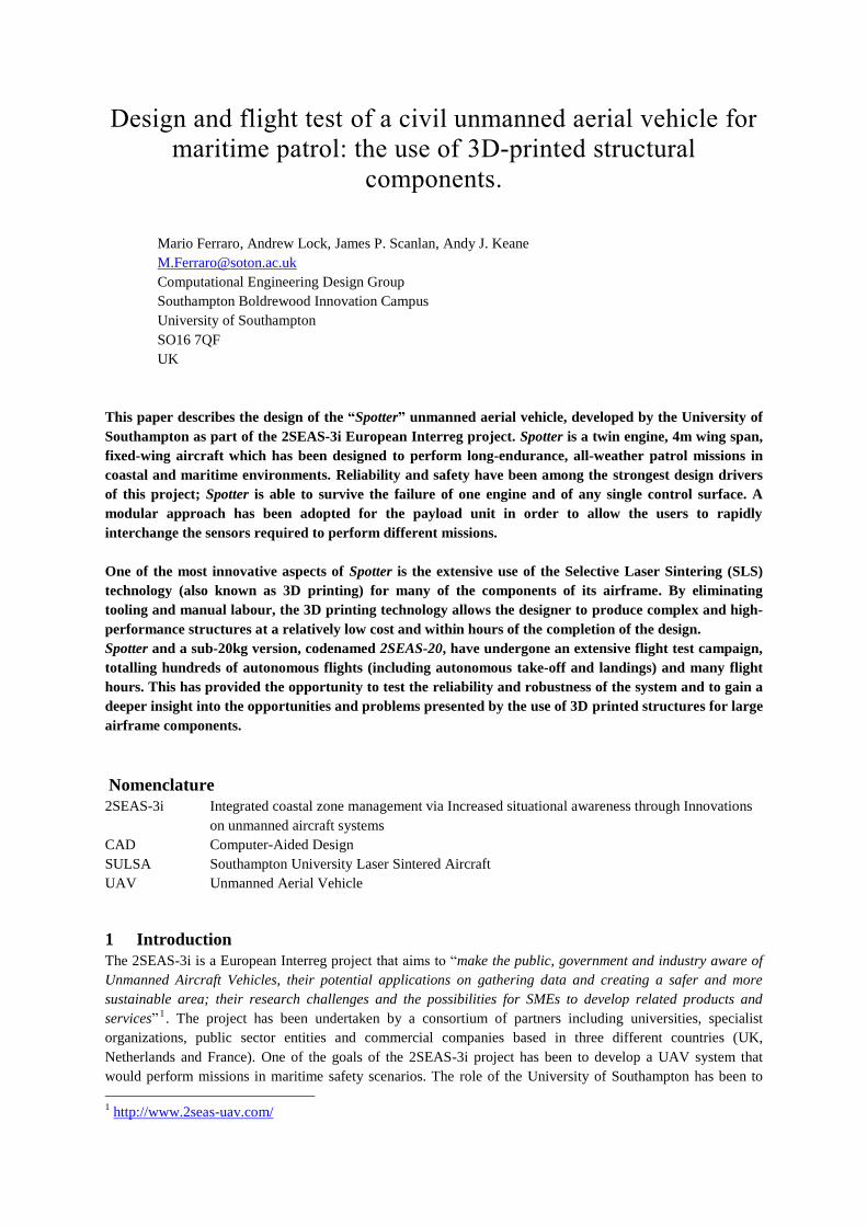
Spotter requirements in terms of supporting infrastructure are minimal. The aircraft can take-off and land from
semi-prepared fields in less than 150m. It can be disassembled and carried in a box of 1.2m high, 0.7m wide and
1.4m long (Figure 3).This allows the aircraft to be transported in a medium-sized van and thanks to quick
assembly features it can be deployed within 15 minutes.
a
b Figure 3 – (a) Spotter partly disassembled for transportation. (b) Spotter in the flight box
3 Rapid manufacturing of airframe components through Selective Laser Sintering
One of the biggest design challenges posed by the 2SEAS-3i project was tight timescale available for the system
development. The team had to build and test the UAV in less than two years (allowing time for a few design
iterations). This pointed at the use of rapid manufacturing techniques and off the shelf components. Carbon fibre
tubes have been used for the wing spars, empennage spars and tail booms. The wing and empennage
aerodynamic surfaces have been manufactured from CNC hot-wire cut foam coated with protective material.
The parts that required a higher level of detail and geometrical complexity were instead produced using a
selective laser sintered polymer. A great effort was placed on producing a set of parts that needed little or no
manual labour, hence reducing the human work to merely assembling components. Thanks to this design

approach, it was possible to go from the CAD model to the final airframe in two weeks with the help of only
two technicians (Figure 4).
a
b Figure 4 – (a) 2SEAS-20 exploded view. (b) 2SEAS-20 in flight.
The SLS technique is of particular interest because it induces a novel approach to the design of parts: the
designer is freed from traditional manufacture constraints and can focus on optimising the geometry for
functionality, assembly and structural performance [8, 19–21]. In the following sections the SLS process is
briefly described and its impact on the design decision illustrated through the description of one of the most
complex parts of the airframe.
3.1 Short description of Selective Laser Sintering of nylon
The Selective Laser Sintering is an additive manufacturing technique in which a powder of raw material is
sintered together by a laser beam. It is available in a number of variants that use different materials including
metals, polymers, and combinations of the two [4]. In this work, the focus is on nylon based SLS because of its
versatility in terms of geometry, the maximum size achievable and its relatively low cost. Nylon is a synthetic
polymer that has excellent durability and chemical resistance coupled with respectable mechanical properties.
SLS nylon mechanical properties are only marginally inferior to the equivalent injected nylon. The properties of
the material used in the 2SEAS-3i project are given in
Table 2.
Material Specification: Nylon 12
Density of Laser Sintered Part 0.9 to 0.95g/cm³
Tensile Modulus 1700 ± 150MPa
Tensile Strength 45 ± 3MPa
Elongation at Break 20 ± 5%
Flexural Modulus 1240 ± 130MPa
Table 2 – Nylon properties (source 3T-RPD)
The SLS process starts with the printer applying a thin layer of nylon powder in a chamber at a temperature
slightly lower that the material’s melting point. A laser beam selectively heats and hence bonds together (sinters)
the particles of the first layer of the object. A piston then lowers the chamber by the layer thickness, a new layer
of powder is applied and the laser sintering is repeated. The process continues layer by layer, until the desired 3-
dimensional geometry is achieved. In the end, the part is loosely contained in a “cake” of powder from which it
can be easily removed after a cooling period (dependant on the size and geometry of the part). The technicians
then remove remaining powder by blasting air onto the part (Figure 5).

a
b
Figure 5 – (a) “cake” of powder containing the final part. (b) Technician removing powder from the final part.
The only geometrical constraint is the maximum size achievable for the single part, which depends on the size
of the SLS printer. Even structures with enclosed cavities can be printed, but the cavities will be filled with un-
sintered powder. Integrated assemblies are also possible: for example, Figure 5b shows a UAV wing printed
with a hinged control surface.
3.2 Designing for 3d-printing: the integral fuel tank
The inner wing of the Spotter is an emblematic example of how the designers can exploit the advantages of SLS
manufacturing in order to obtain high-performance multifunctional structures at a competitive price. The
mechanical properties of nylon are poor if compared with materials more traditionally used for airframes, such
as aluminium or carbon fibre composites. Moreover, the cost of producing large 3D-printed parts can be
relatively high for mass production if compared with traditional techniques such as injection moulding or high
pressure die-casting: the break-even point depends on a number of factors, including the shape, size, material
and design characteristics of the object and whether the assembly and post processing cost is included in the cost
analysis. Results of previous studies vary from a few tens of units to several thousand [8, 22]. With SLS, the
number of details and the complexity of the geometry do not impact the cost of the parts and little or no manual
labour is required after the part is removed from the printer. By exploiting these characteristics, the designer can
achieve parts with very high strength to weight ratio and decrease the total cost of the airframe by reducing the
number of parts and hence reduce the assembly cost.
Figure 6 – Spotter’s inner wing assembly. The integral fuel tank is shown in transparency.

The inner wing assembly is showed in Error! Reference source not found.: it consists of a large 3D-printed
part (transparent) connected to the inner flap and the wing spars. The fuel tank, shown in Figure 7, exploits an
integral design approach to serve many functions:
- Contain the fuel
- Contribute to the lift generation of the aircraft
- Provide hinge line for the central flap and mounting point for its servo actuator
- Provide the structural connection between the aircraft main spars and the payload
- Provide the connection interface with the payload and it’s retaining mechanism
- Connect the two fuselages and provide the cable routing between them and to the payload pod
- Provide mounting points for the fuel level sensors
a
b
Figure 7 – Two views of the Spotter’s integral fuel tank
The fuel tank has a wall thickness of 1.2mm and is reinforced by a system of crossing webs and stringers. The
overall part weighs just under 1kg and can contain up to 8 litres of fuel, hold a 5kg payload and is designed to
cope with loads of more than 7g. The benefits of 3D printing can be illustrated through a description of some of
the tank’s main design features.
The T-shape of the integral fuel tank ensures that the pick-ups are submerged in fuel until the tank is completely
empty. The airfoil shaped section also provides a low-drag mounting pylon for the payload. In order to avoid
trapping fuel in the reinforcement framework, the stringers in the bottom surface are printed externally, as
visible in Figure 7-b and Figure 8. The tank is divided in two halves by a longitudinal baffle to prevent the fuel
from sloshing from one side to the other. The sine-waved design provides the baffle with great rigidity while
avoiding the complication of the framework. The two halves of the tank are connected through small holes at the
bottom of the baffle that allow the aircraft to exploit the whole fuel load even when running on a single engine.
A tank liner is applied to the internal volume to seal the tank and avoid absorption of fuel by the porous 3D
printed nylon. The part has a number of built-in connection interfaces, these allowing technicians to quickly
couple the tank with other mechanical parts and avionics sub-systems.

Figure 8 – Fuel tank section view
One of the greatest advantages of 3D printing is the fact that the designers don’t have to commit to early
decisions and can continue to improve and adapt the design at no extra cost. The integral fuel tank has
undergone a series of design iterations as a result of knowledge gathered through further analysis, more
demanding requirements and changes in the other airplane’s systems. Two examples are described below.
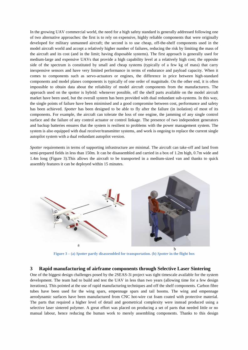
Figure 9 and Figure 10 show the result of stress computation performed on one of the design iterations of the
part using a finite element model. In this test, the model was constrained with frictionless supports at the spar
locations (approximated as infinitely rigid) and the inertial load of fuel and payload during an asymmetric 7g
landing was applied. The pictures show how both the framework and the baffle contribute to transfer the load to
the carbon fibre spars, leaving the skin with a relatively low stress level. The safety factor is higher than 5 in all
the points apart from a small region of stress concentration around the baffle’s holes where it is 3.5 (Figure 10b).
Thanks to the flexibility of 3D-printing, it has been possible to reinforce this region in the next iteration of the
part (Figure 11).
Another example of design iteration is shown in Figure 12. In the first version of the integral fuel tank, designed
for the 2SEAS-20, the tank’s cap was designed such that, when screwed in, it was completely flush with the
upper surface of the wing. To achieve this, the cap thread was penetrating into the tank volume (Figure 12a).
This was causing two problems: firstly, it was not possible to exploit the volume of the tank above the level of
the cap’s interface; secondly, the female thread was on the inside of the tank and hence was difficult to protect
from the tank liner during the sealing operation, which in turn caused a poor coupling between the two threaded
parts. The second iteration, shown in Figure 12b, solves both these issues. The fuel cap interface has been
slightly raised over the wing’s top surface and protected with an aerodynamic fairing, and the thread coupling
has been reversed (male thread on the tank and female on the cap). In this new version, used on Spotter, the fuel
capacity is increased by 30%.
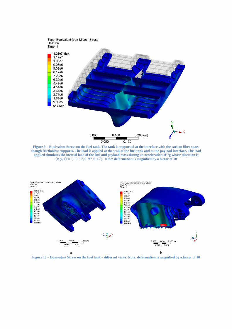
Figure 9 – Equivalent Stress on the fuel tank. The tank is supported at the interface with the carbon fibre spars
though frictionless supports. The load is applied at the wall of the fuel tank and at the payload interface. The load
applied simulates the inertial load of the fuel and payload mass during an acceleration of 7g whose direction is ( ) ( ). Note: deformation is magnified by a factor of 10
a
b Figure 10 – Equivalent Stress on the fuel tank – different views. Note: deformation is magnified by a factor of 10

a
b
Figure 11 – Design iteration example: the hole in the baffle of the fuel tank has been reinforced to avoid stress
concentration.
a
b
Figure 12 – Design iteration example: the redesign of the tank’s cap has increased the fuel volume by 30%
4 Flight tests
2SEAS-20 and Spotter have undergone a rigorous flight test campaign that started in May 2013 with the first
flight of 2SEAS-20. Spotter had its maiden flight in April 2014 and has since accumulated more than 300 flights.
The tests were designed to record the flight performance and to prove the effectiveness of the redundant design
in several failure scenarios. They were performed following an incremental risk approach: the first flights were
aimed at assessing the general handling characteristics and were performed under the control of a human pilot.
During this phase the entire flight envelope was explored and the flight performance recorded.
The second phase has been dedicated to the automatic flights performed using the on-board autopilot. During
this stage, hundreds of automatic take-offs and landings and several completely automated flights have been
accomplished. The results are illustrated by Figure 13, which shows the trails and the landing touch down points
of 23 completely automated flights performed at the port of Ramsgate in February 2014.
Finally, the team has dedicated particular attention to the tests simulating sub-system failures. These tests
included:
- Single engine failure
- Failure of the engine throttle servo actuator in a position that commanded full power
- Jamming of one of elevator, aileron, rudder or flap in the worst possible position
- Failure of one of the independent power buses causing complete loss of power to half of the control
surfaces
In all the cases the UAV has been able to retain sufficient power and control authority to land undamaged.
a
b
Figure 13 – (a) Trails of 23 automatic flights at Ramsgate port. (b) Automatic landing touch-down points
Alongside the many successful flights, there were a few mishaps during the testing, the most severe of which
was a crash landing that damaged most of the airframe components. The accident was due to the failure of a flap
during a remotely piloted flight; the aircraft exceeded the maximum speed in the full-flap configuration causing
one of the flap servo protection fuses to blow. The ground crew failed to promptly recognise the cause of the
resulting rolling moment and although the pilot was initially able to regain some control by fully deflecting the
ailerons, there was not enough control authority left on approach to allow an emergency landing. The aircraft
impacted the runway at a 40 bank angle causing it to cartwheel resulting in damage to the structure. A number
of changes have been implemented in the airframe and procedure to avoid the repetition of the accident. These
include more powerful flap servos to provide a larger safety factor on the maximum torque and a more strict
policy concerning flap deployment. Also, the two flap servos have been connected electronically so that the
input power is cut to both of them simultaneously if an anomaly is detected. This mishap has also provided an
opportunity to validate one of the design features: despite the damage to the fuselages, wings and empennage,
the payload pod and the fuel tank have been protected by the airframe configuration and have survived the crash
undamaged.
Until now, all the tests have been performed keeping a visual line of sight with the UAV in order to constantly
have a human safety pilot ready to override the autopilot inputs in case of emergency. The goal of the upcoming
months is to perform missions with incrementally longer operative range in segregated airspace. The aircraft
position will be monitored using a secondary radar as well as the GPS.
5 Conclusions
This paper has briefly described the characteristics of Spotter, a 35kg unmanned aircraft designed for maritime
patrol missions. Spotter presents some unique characteristics for an airplane of this size: it has double redundant
systems for increased safety and reliability and is produced through rapid manufacturing techniques. In
particular, the use of selective laser sintered nylon parts and the impact that this technology has on the design of
the parts have been demonstrated through the description of the integral fuel tank, one of the most complex parts
of the airframe.
The paper has mentioned some of the results of the initial flight tests: the airplane has exhibited excellent flight
characteristics and the validity of the dual redundant approach has been demonstrated in many cases. The flight
testing has also validated the suitability of 3D printing for the manufacture of major airframe components, with
the SLS nylon parts withstanding the rigours of normal operation. Further development of the airframe and more
ambitious flight testing is planned for the near future in order to enhance the capabilities of the system.

References
1. Wohlers, T.: Tracking Global Growth in Industrial-Scale Additive Manufacturing. 3D Print. Addit.
Manuf. 1, (2014).
2. Yeh, C.-C.: Trend Analysis for the Market and Application Development of 3D Printing. Int. J. Autom.
Smart Technol. 4, 1–3 (2014).
3. Bryden, D.: CAD and Rapid Prototyping for Product Design. Laurence King Publishing Limited (2014).
4. Wong, K. V., Hernandez, A.: A Review of Additive Manufacturing. ISRN Mech. Eng. 2012, 1–10
(2012).
5. Hopkinson, N., Dicknes, P.: Analysis of rapid manufacturing - using layer manufacturing processes for
production. Proc. Inst. Mech. Eng. Part C J. Mech. Eng. Sci. (2003).
6. Kulkarni, P., Marsan, A., Dutta, D.: A review of process planning techniques in layered manufacturing.
Rapid Prototyp. J. Vol. 6, pp.18 – 35 (2000).
7. Groover, M.P.: Fundamentals of modern manufacturing: materials processes, and systems. John Wiley
& Sons (2010).
8. Atzeni, E., Salmi, A.: Economics of additive manufacturing for end-usable metal parts. Int. J. Adv.
Manuf. Technol. 62, 1147–1155 (2012).
9. Petrovic, V., Haro Gonzalez, J.V., Jordá Ferrando, O., Delgado Gordillo, J., Blasco Puchades, J.R.,
Portolés Griñan, L.: Additive layered manufacturing: sectors of industrial application shown through
case studies. Int. J. Prod. Res. 49, 1061–1079 (2011).
10. Gasser, A., Backes, G., Kelbassa, I.: Laser Additive Manufacturing - Laser Metal Deposition ( LMD )
and Selective Laser. Laser Addit. Manuf. 58–63 (2010).
11. A Military-Grade Drone That Can Be Printed Anywhere, http://www.wired.com/2014/09/military-
grade-drone-can-printed-anywhere/.
12. 3D printing trials of unmanned aircraft broaden the possibilities for this emergent technology - News
releases - News - The University of Sheffield, http://www.sheffield.ac.uk/news/nr/3d-printing-trials-of-
unmanned-aircraft-1.364084.
13. Marks, P.: 3D printing: The world’s first printed plane, http://www.newscientist.com/article/dn20737-
3d-printing-the-worlds-first-printed-plane.html?full=true#.VBWAqfn-N8E, (2011).
14. Ferraro, M., Gorissen, D., Scanlan, J., Keane, A., Quaranta, E., Schumann, B., van Schaik, J., Bolinches
i Gisbert, M.: Toward Value-Driven Design of a Small, Low-Cost UAV. 53rd Structures, Structural
Dynamics, and Materials Conference (SDM) (2012).
15. Gorissen, D., Quaranta, E., Ferraro, M., Schumann, B., Schaik, J. Van, Gisbert, M.B.I., Keane, A.,
Scanlan, J.: Value-Based Decision Environment: Vision and Application. J. Aircr. 51, 1360–1372
(2014).
16. Surendra, A., Ferraro, M., Schumann, B., van Schaik, J., Daniels, J.J., Gorissen, D., Scanlan, J.P., Keane,
A.J.: The Challenges of using Value-Driven Design for practical design of UAVs. J. Aerosp. Oper. 1,
377–386 (2012).
17. Schumann, B., Ferraro, M., Surendra, A., Scanlan, J.P., Fangohr, H.: Better Design Decisions Through
Operational Modeling During the Early Design Phases. J. Aerosp. Inf. Syst. 11, (2014).

18. CAA: CAP 722 - Unmanned Aircraft System Operations in UK Airspace – Guidance. (2012).
19. Hague, R., Campbell, I., Dickens, P.: Implications on design of rapid manufacturing. Proc. Inst. Mech.
Eng. Part C J. Mech. Eng. Sci. 217, 25–30 (2003).
20. Hague, R., Mansour, S., Saleh, N.: Design opportunities with rapid manufacturing. Assem. Autom. 23,
346–356 (2003).
21. Gibson, I., Goenka, G., Narasimhan, R., Bhat, N.: Design Rules for Additive Manufacture. Proceedings
of the Solid Freeform Fabrication 2010 international symposium. pp. 705–716. , Austin, Texas (2010).
22. Ruffo, M., Tuck, C., Hague, R.: Cost estimation for rapid manufacturing-laser sintering production for
low to medium volumes. J. Eng. Manuf. (2006).