Embed Size (px)
Citation preview

Design and Field Test of a Full Scale Performance Augmentation Network (PAN)
2014 GMRC Research Project
W. Norman Shade, PE & John J. Bazaar, ACI Services, Inc. Kelly Eberle & Mehdi Arjmand, Beta Machinery Analysis
Glen F. Chatfield & Dale K. Wells, OPTIMUM Pumping Technology Scott Schubring, Williams
1
2014 GMRC Gas Machinery Conference Nashville, TN – October 6-8, 2014
2
Design and Field Test of a Full Scale PAN
End User Interest and Objectives
• Support advancement of new technology • Significant commercial benefit from
• More flow from compressors for given driver size & rating • Higher efficiency reduces fuel cost & specific exhaust emissions • Reduce no. & size of multiple parallel drivers at a station
• Such advancements may become mandatory in future • Recently announced DOE efficiency initiative • EPA GHG reduction initiatives
3
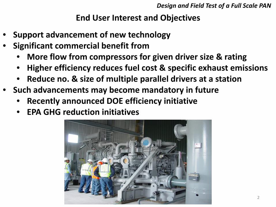
PAN & Bottle Systems Are Fundamentally Different
PAN Systems
95% recovered
all throws Interleaved
Insignificant
tuned pipe lengths tuned pipe diameters
primary Y or W junctions secondary Y junctions
Design and Field Test of a Full Scale PAN
Bottle Systems
95% dissipated
Individually
can be large
expansion bottles baffles
choke tubes orifice plates
Pulsation energy Throw phasing Pressure & HP losses Components
4
Design and Field Test of a Full Scale PAN
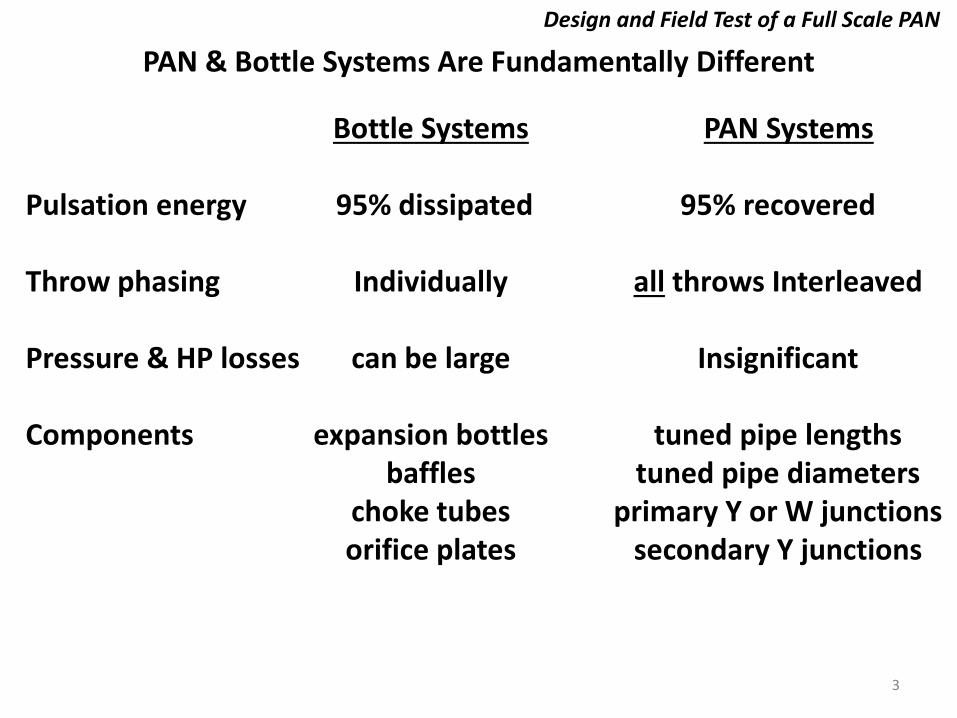
Brief PAN Technology Development History
• 1994 engine technology development begins with Univ. of Belfast • 2006 modeled 1st compressor cylinder • 2007 GMC paper on 1st PAN compressor model • 2008 GMC paper on lab air compressor PAN testing • 2009 GMC paper on TGT Ellisburg station PAN field test • 2010 El Paso sta. 96 PAN conversion designed; project suspended • 2011 GMRC project - PAN conversion at El Paso Batesville station • 2011 GMC paper on efficiency increase with PAN tuning • 2012 El Paso sale cancelled Batesville host & GMRC project on hold • 2013 GMRC project - PAN conversion at Williams sta. 85; withdrawn • 2014 GMRC project – Williams Zick station (this paper!)

5
Design and Field Test of a Full Scale PAN
Project Objectives
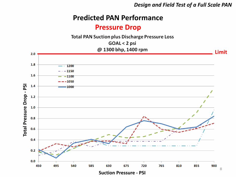
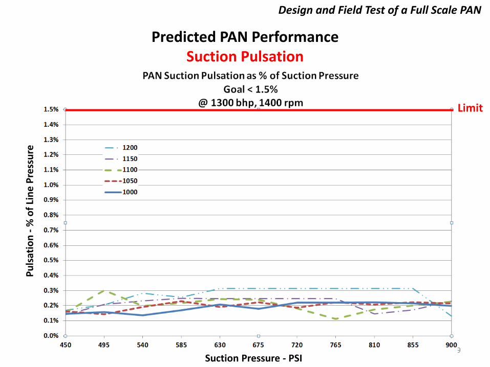
Primary • Cover operating range from 450-900 suction & 1000-1200 discharge • Maximize capacity at all conditions at rated power & speed • Total system (line to line) pressure drop <2.0 psig at all conditions • Control pulsations to <1.5% of line pressure level at all conditions • Control mechanical vibrations and stress levels to API 618 M5 • 10% reduction in BHP/MMSCFD at the high flow condition (compared to existing bottle unit) Secondary • Validate predictive accuracy of OPT VPS software • Demonstrate ability to create optimal PAN that simultaneously achieves all objectives • Achieve performance with unloading limited to HE VVCPs • Fit factory-built PAN entirely onto the compressor package skid • Dependable operation over 1300 to 1400 rpm speed range

6
Design and Field Test of a Full Scale PAN
Compressor Package Specifications
• Caterpillar G3516 gas engine driver • 1380 BHP @ 1400 rpm • Ariel JGT/4 4.5” stroke compressor • (4) 6.75” cylinders with HE VVCP • Single stage • Suction pressure 450 to 900 psig • Discharge pressure 1000 to 1200 psig • Separate motor-driven cooler • Single suction scrubber

7
Design and Field Test of a Full Scale PAN
Specified PAN System Design Points
Operating Condition Suction Pressure (psig)
Discharge Pressure (psig)
Low suct; Low disch. (low flow) 450 1000 Low suct; high disch. (high ratio) 450 1200 Center of operating map (design pt.) 675 1100 High suct; low disch. (low ratio/high flow) 900 1000 High suct; high disch. 900 1200
8
Design and Field Test of a Full Scale PAN
Predicted PAN Performance Pressure Drop
Limit
Tota
l Pre
ssur
e Dr
op -
PSI
Suction Pressure - PSI
9
Design and Field Test of a Full Scale PAN
Predicted PAN Performance Suction Pulsation
Limit
Puls
atio
n - %
of L
ine
Pres
sure
Suction Pressure - PSI

10
Design and Field Test of a Full Scale PAN
Predicted PAN Performance Discharge Pulsation
Limit
Suction Pressure - PSI
Puls
atio
n - %
of L
ine
Pres
sure

11
Design and Field Test of a Full Scale PAN
Predicted Pressure Drop Reduction PAN Unit vs. Baseline Bottle Unit
1300 BHP @1400 rpm
Table Average – 91.5%
12
Design and Field Test of a Full Scale PAN
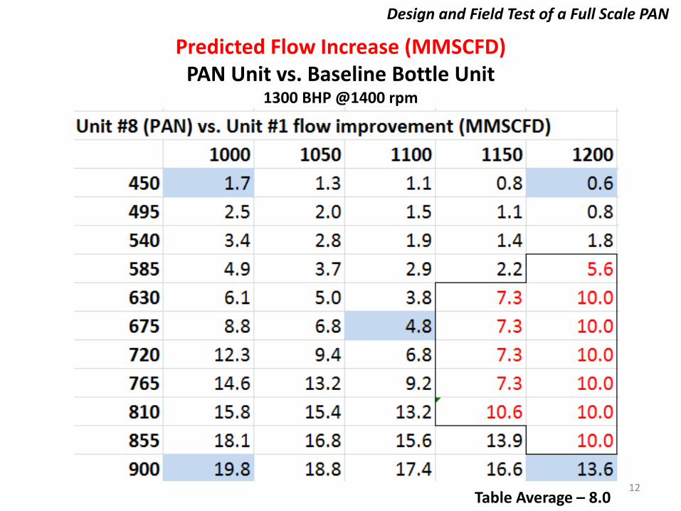
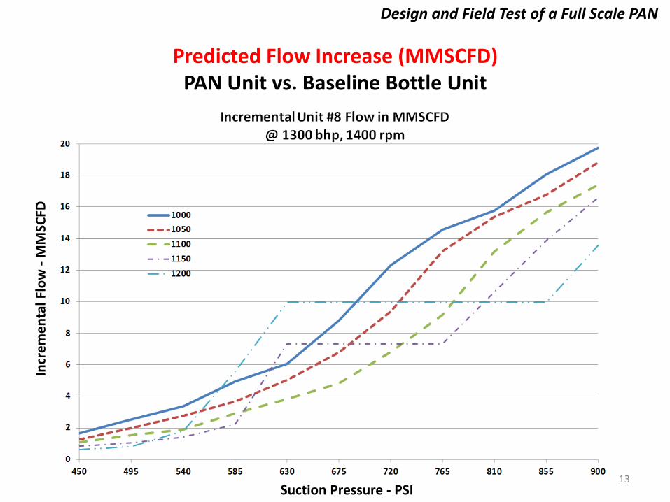
Predicted Flow Increase (MMSCFD) PAN Unit vs. Baseline Bottle Unit
1300 BHP @1400 rpm
Table Average – 8.0
13
Design and Field Test of a Full Scale PAN
Predicted Flow Increase (MMSCFD) PAN Unit vs. Baseline Bottle Unit
Suction Pressure - PSI
Incr
emen
tal F
low
- M
MSC
FD

14
Design and Field Test of a Full Scale PAN
Predicted % Improvement in BHP/MMSCFD PAN Unit vs. Baseline Bottle Unit
1300 BHP @1400 rpm
Table Average – 13.5%

15
Design and Field Test of a Full Scale PAN
Predicted % Improvement in BHP/MMSCFD PAN Unit vs. Baseline Bottle Unit
Goal @ 1000 PD
BHP/
MM
SCFD
Red
uctio
n - %
16
Design and Field Test of a Full Scale PAN
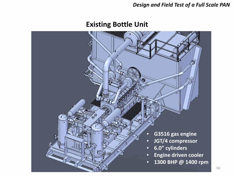
Existing Bottle Unit
• G3516 gas engine • JGT/4 compressor • 6.0” cylinders • Engine driven cooler • 1300 BHP @ 1400 rpm
17
Design and Field Test of a Full Scale PAN
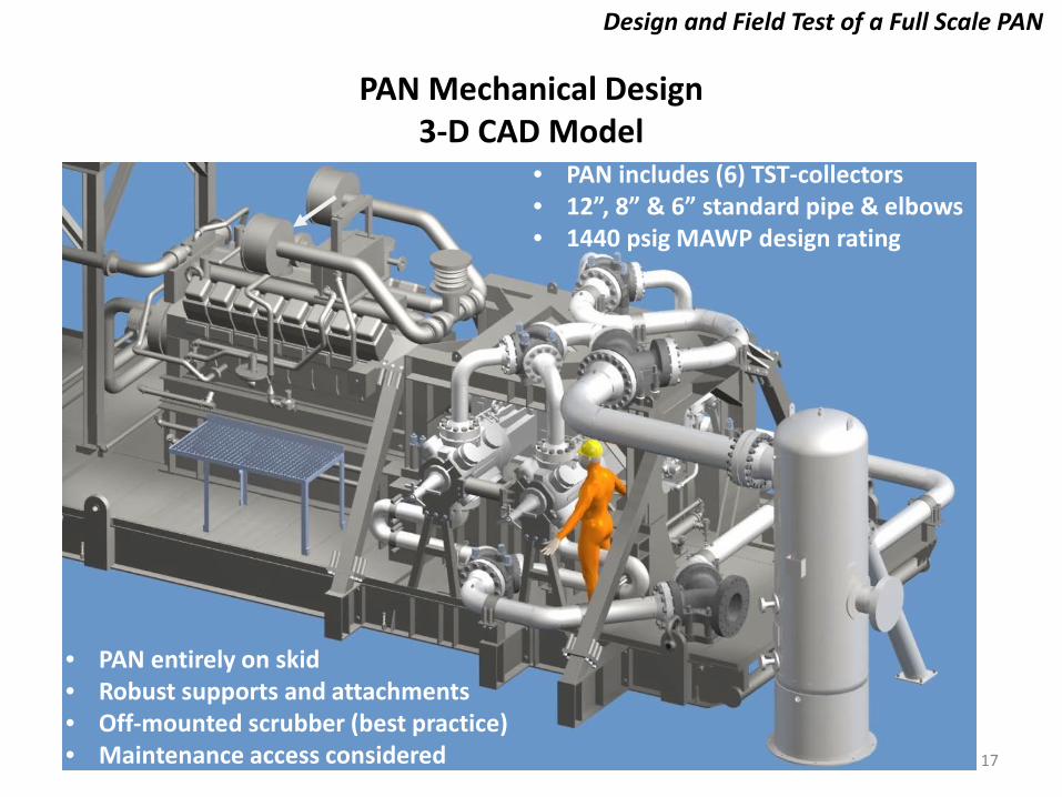
PAN Mechanical Design 3-D CAD Model
• PAN entirely on skid • Robust supports and attachments • Off-mounted scrubber (best practice) • Maintenance access considered
• PAN includes (6) TST-collectors • 12”, 8” & 6” standard pipe & elbows • 1440 psig MAWP design rating

18
Design and Field Test of a Full Scale PAN
PAN Mechanical Design 3-D CAD Model
Suction PAN designed for 45° Phase Delay
Discharge PAN designed for 135° Phase Delay

19
Design and Field Test of a Full Scale PAN
PAN Mechanical Design Completed Package

20
Design and Field Test of a Full Scale PAN
PAN Mechanical Design Completed Package

21
Design and Field Test of a Full Scale PAN
PAN Mechanical Design TST-Collectors
• (4) 8x6x6 Y-collectors • (2) 12x8x8 Y-collectors • ASTM A395 Cast DI • 1500 psig MAWP • Serialized Items
22
Design and Field Test of a Full Scale PAN
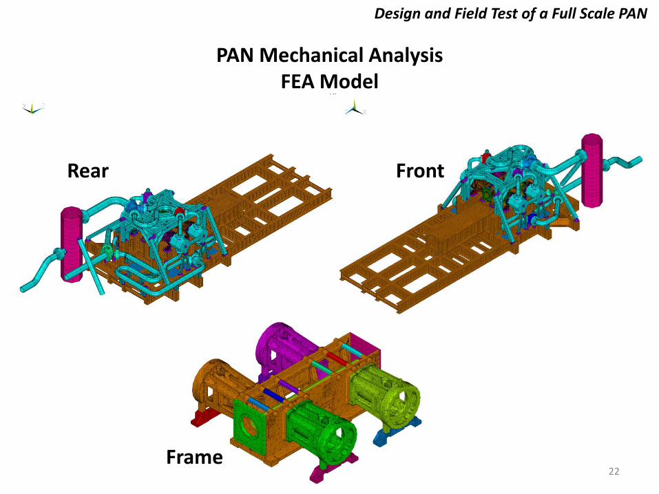
PAN Mechanical Analysis FEA Model
Rear Front
Frame

Dynamic Loads • Compressor reciprocating and rotating inertia • Cylinder gas force (stretch force) • Crosshead guide force • Pressure pulsations
24
Design and Field Test of a Full Scale PAN
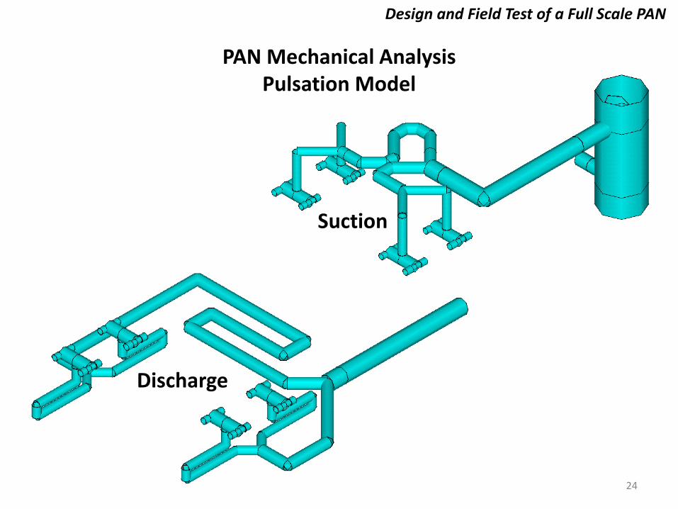
Suction
Discharge
PAN Mechanical Analysis Pulsation Model

25
Design and Field Test of a Full Scale PAN
PAN Mechanical Analysis Maximum Shaking Forces - Suction
Guideline
Shak
ing
Forc
e (lb
pk-
pk)
Resonance at 4x Compressor Speed
26
Design and Field Test of a Full Scale PAN
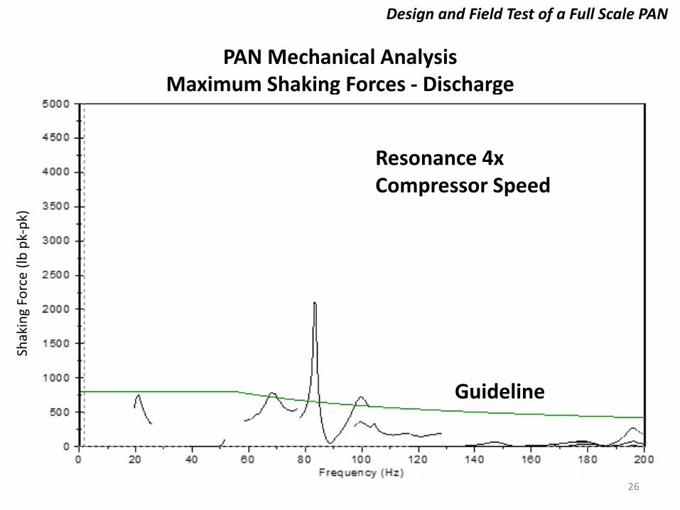
PAN Mechanical Analysis Maximum Shaking Forces - Discharge
Guideline
Shak
ing
Forc
e (lb
pk-
pk)
Resonance 4x Compressor Speed
27
Design and Field Test of a Full Scale PAN
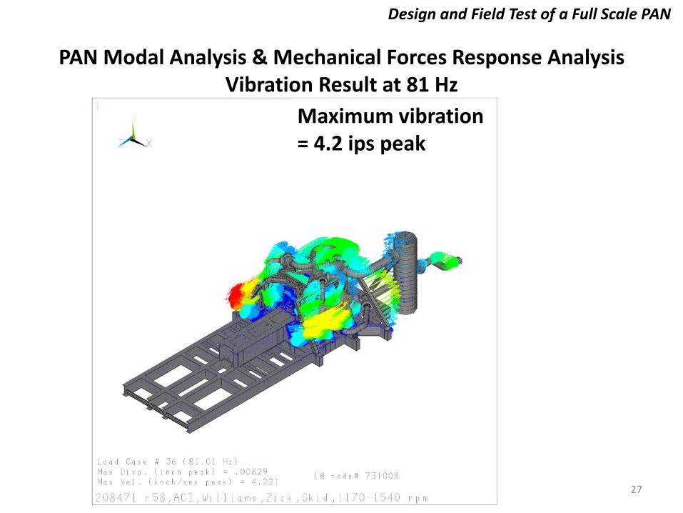
PAN Modal Analysis & Mechanical Forces Response Analysis Vibration Result at 81 Hz
Maximum vibration = 4.2 ips peak

28
Design and Field Test of a Full Scale PAN
PAN Modal Analysis & Mechanical Forces Response Analysis Vibration Result at 81 Hz – Cyl. 1 & 3 Side View
Maximum vibration = 4.2 ips peak

29
Design and Field Test of a Full Scale PAN
PAN Modal Analysis & Mechanical Forces Response Analysis Dynamic Stress at 81 Hz
Maximum dynamic stress = 3,460 psi peak

30
Design and Field Test of a Full Scale PAN
Preliminary Results
• Vibration = 4.1 ips peak at 81 Hz o Guideline is 1 ips peak
• Dynamic stress = 3,460 psi peak at 81 Hz o Guideline is 1,500 psi peak
• Assumptions o 81 Hz resonance occurs (81 Hz at 4x = 1215
rpm). Normal operating speed is 1300-1400 rpm.
o Damping ratio is 1%. Typical damping ratio for this mode is 2% to 4%.
• Vibration and dynamic stress will be lower at normal operating speed and higher damping
31
Design and Field Test of a Full Scale PAN
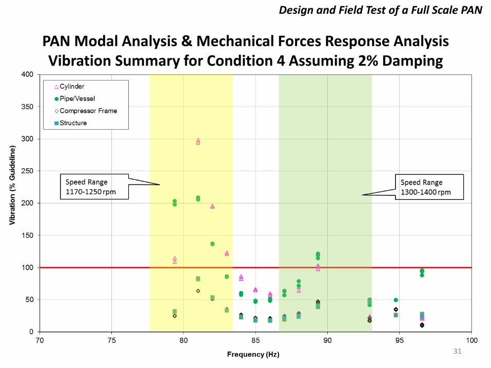
PAN Modal Analysis & Mechanical Forces Response Analysis Vibration Summary for Condition 4 Assuming 2% Damping
32
Design and Field Test of a Full Scale PAN
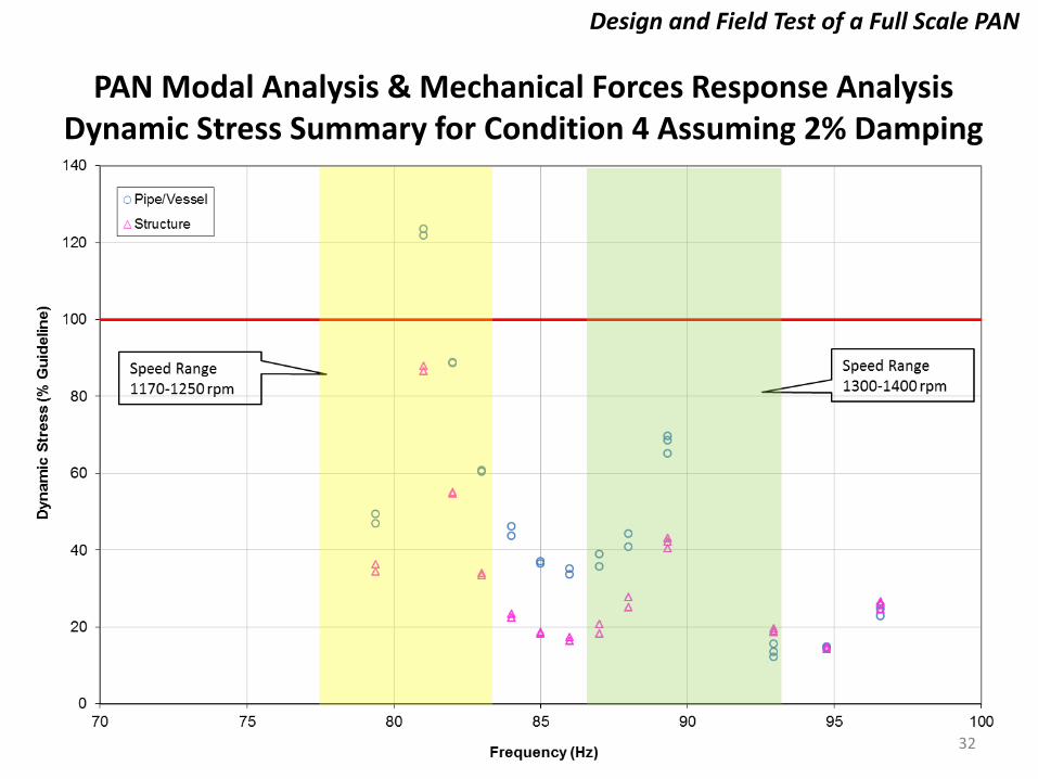
PAN Modal Analysis & Mechanical Forces Response Analysis Dynamic Stress Summary for Condition 4 Assuming 2% Damping

33
Design and Field Test of a Full Scale PAN
PAN Modal Analysis & Mechanical Forces Response Analysis Scrubber Detuning
12” to 18” diameter cut-out in skirt
Recently scrubber inlet piping design was finalized. Potential scrubber resonance.
Proposed Solution: Skirt Cut-out

34
Design and Field Test of a Full Scale PAN
PAN Modal Analysis & Mechanical Forces Response Analysis Mechanical Recommendations
• Design & assembly care to avoid pipe strain • Small bore piping natural frequency testing • Shop bump testing to verify model MNF predictions • Shop bump testing to verify damping ratio assumptions • Field bump testing to verify MNF placement & response • Running test to verify acceptable vibration limits at first start-up • Inspect pipe clamps, flange studs & other critical fasteners at regular intervals to ensure there is no vibratory loosening.
35
Design and Field Test of a Full Scale PAN
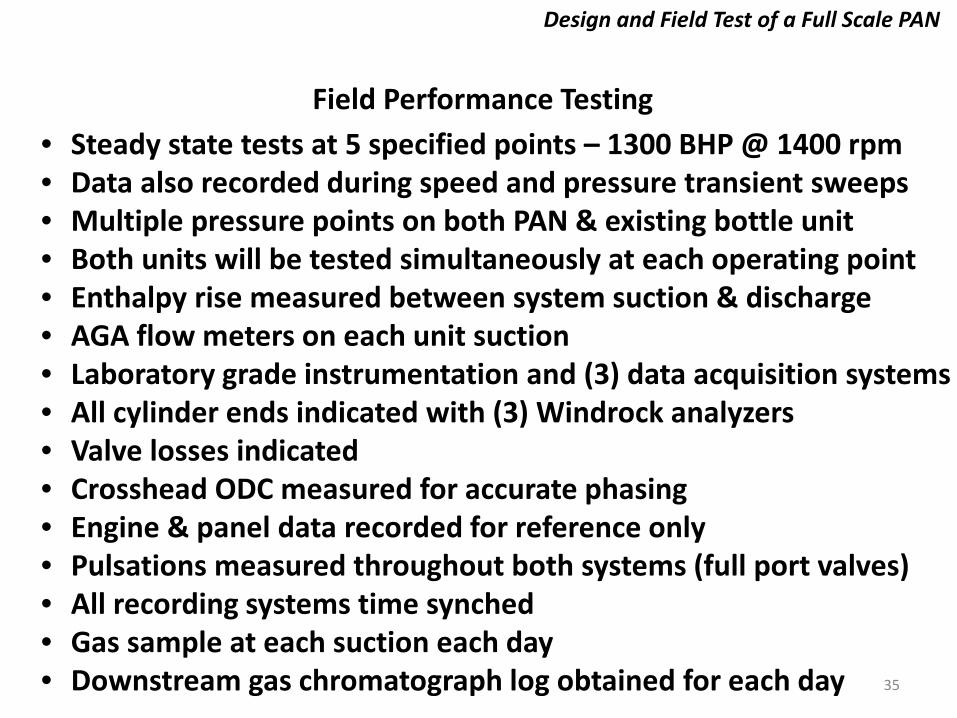
Field Performance Testing • Steady state tests at 5 specified points – 1300 BHP @ 1400 rpm • Data also recorded during speed and pressure transient sweeps • Multiple pressure points on both PAN & existing bottle unit • Both units will be tested simultaneously at each operating point • Enthalpy rise measured between system suction & discharge • AGA flow meters on each unit suction • Laboratory grade instrumentation and (3) data acquisition systems • All cylinder ends indicated with (3) Windrock analyzers • Valve losses indicated • Crosshead ODC measured for accurate phasing • Engine & panel data recorded for reference only • Pulsations measured throughout both systems (full port valves) • All recording systems time synched • Gas sample at each suction each day • Downstream gas chromatograph log obtained for each day

36
Design and Field Test of a Full Scale PAN
Field Performance Testing PAN System Test Points
37
Design and Field Test of a Full Scale PAN
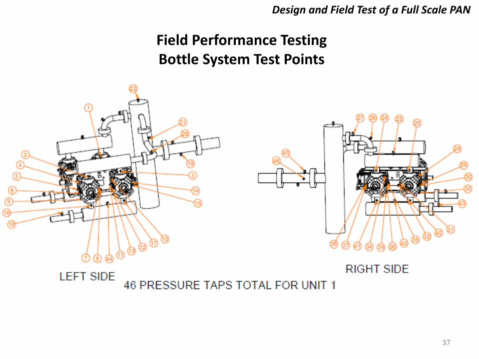
Field Performance Testing Bottle System Test Points

38
Design and Field Test of a Full Scale PAN
Field Performance Testing • Test team of 13-14 people with detailed protocol established. • Calculation methods pre-established. • VMG and NIST gas data. • Data adjusted for differences in cylinders (based on predictions). • Comparison of measured and predicted results for both units. • Unfortunately, construction delays prevented test data for paper. • Mechanical testing this week. • Performance testing late October awaiting higher gas flows to reach high end of suction pressure required for test points.
39
Design and Field Test of a Full Scale PAN
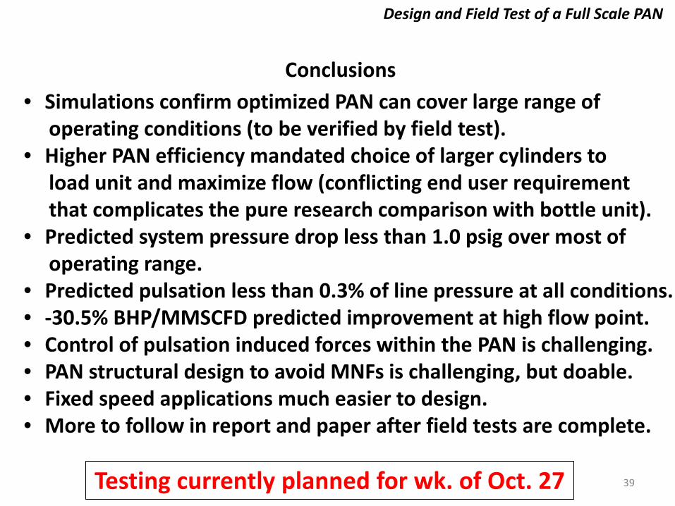
Conclusions • Simulations confirm optimized PAN can cover large range of operating conditions (to be verified by field test). • Higher PAN efficiency mandated choice of larger cylinders to load unit and maximize flow (conflicting end user requirement that complicates the pure research comparison with bottle unit). • Predicted system pressure drop less than 1.0 psig over most of operating range. • Predicted pulsation less than 0.3% of line pressure at all conditions. • -30.5% BHP/MMSCFD predicted improvement at high flow point. • Control of pulsation induced forces within the PAN is challenging. • PAN structural design to avoid MNFs is challenging, but doable. • Fixed speed applications much easier to design. • More to follow in report and paper after field tests are complete.
Testing currently planned for wk. of Oct. 27
40
Design and Field Test of a Full Scale PAN
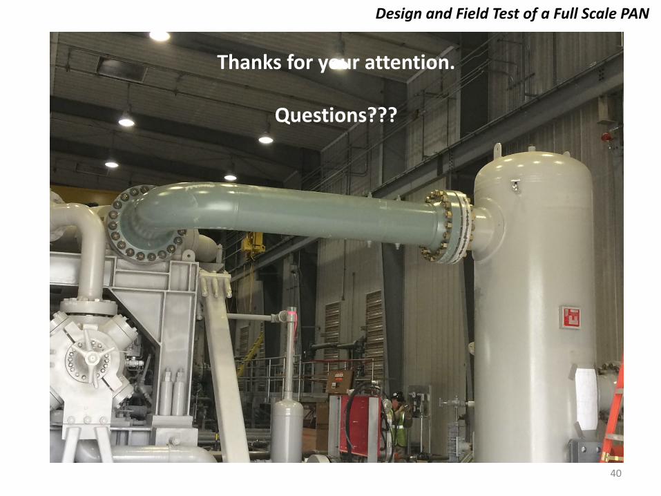
Thanks for your attention.
Questions???


![QUALITY TOOL BOX OSTEOPOROSIS GENERAL & MEDICAL REHABILITATION COUNCIL [GMRC]](https://img.pdfslide.us/doc/110x75/56649e925503460f94b97ba8/quality-tool-box-osteoporosis-general-medical-rehabilitation-council-gmrc.jpg)