Embed Size (px)
Citation preview
7/31/2019 Design and Fabrication of Cnt Sandwhich
http://slidepdf.com/reader/full/design-and-fabrication-of-cnt-sandwhich 1/7
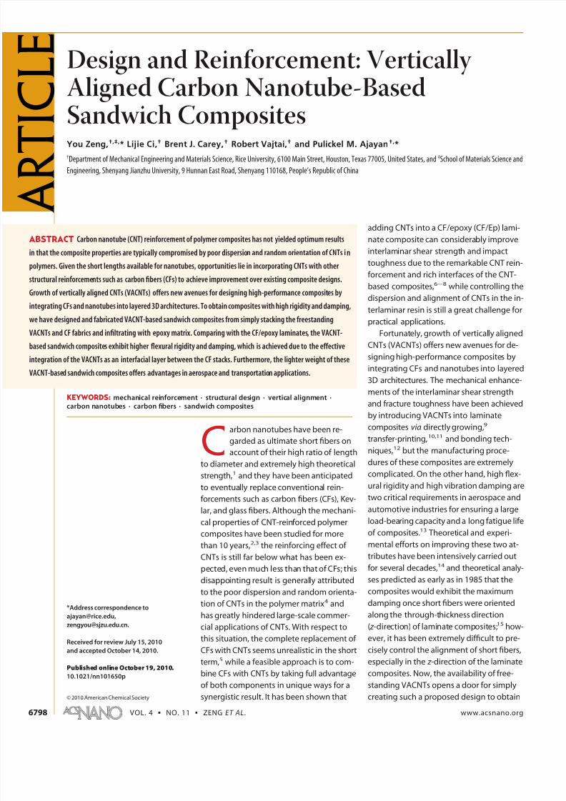
Design and Reinforcement: Vertically Aligned Carbon Nanotube-BasedSandwich CompositesYou Zeng,†,‡,* Lijie Ci,† Brent J. Carey,† Robert Vajtai,† and Pulickel M. Ajayan†,*
†Department of Mechanical Engineering and Materials Science, Rice University, 6100 Main Street, Houston, Texas 77005, United States, and ‡School of Materials Science and
Engineering, Shenyang Jianzhu University, 9 Hunnan East Road, Shenyang 110168, People’s Republic of China
Carbon nanotubes have been re-
garded as ultimate short fibers on
account of their high ratio of length
to diameter and extremely high theoretical
strength,1 and they have been anticipated
to eventually replace conventional rein-
forcements such as carbon fibers (CFs), Kev-
lar, and glass fibers. Although the mechani-
cal properties of CNT-reinforced polymer
composites have been studied for more
than 10 years,2,3 the reinforcing effect of
CNTs is still far below what has been ex-
pected, even much less than that of CFs; this
disappointing result is generally attributed
to the poor dispersion and random orienta-
tion of CNTs in the polymer matrix4 and
has greatly hindered large-scale commer-
cial applications of CNTs. With respect to
this situation, the complete replacement of
CFs with CNTs seems unrealistic in the short
term,5 while a feasible approach is to com-
bine CFs with CNTs by taking full advantage
of both components in unique ways for a
synergistic result. It has been shown that
adding CNTs into a CF/epoxy (CF/Ep) lami-
nate composite can considerably improve
interlaminar shear strength and impact
toughness due to the remarkable CNT rein-
forcement and rich interfaces of the CNT-
based composites,68 while controlling the
dispersion and alignment of CNTs in the in-
terlaminar resin is still a great challenge for
practical applications.
Fortunately, growth of vertically aligned
CNTs (VACNTs) offers new avenues for de-
signing high-performance composites by
integrating CFs and nanotubes into layered
3D architectures. The mechanical enhance-
ments of the interlaminar shear strength
and fracture toughness have been achieved
by introducing VACNTs into laminate
composites via directly growing,9
transfer-printing,10,11 and bonding tech-
niques,12 but the manufacturing proce-
dures of these composites are extremely
complicated. On the other hand, high flex-
ural rigidity and high vibration damping are
two critical requirements in aerospace and
automotive industries for ensuring a large
load-bearing capacity and a long fatigue life
of composites.13 Theoretical and experi-
mental efforts on improving these two at-
tributes have been intensively carried out
for several decades,14 and theoretical analy-
ses predicted as early as in 1985 that the
composites would exhibit the maximum
damping once short fibers were oriented
along the through-thickness direction
( z -direction) of laminate composites;15 how-
ever, it has been extremely difficult to pre-
cisely control the alignment of short fibers,
especially in the z -direction of the laminate
composites. Now, the availability of free-
standing VACNTs opens a door for simply
creating such a proposed design to obtain
*Address correspondence to
Received for review July 15, 2010
and accepted October 14, 2010.
Published onlineOctober19, 2010.
10.1021/nn101650p
© 2010 American Chemical Society
ABSTRACT Carbon nanotube (CNT) reinforcement of polymer composites has not yielded optimum results
in that the composite properties are typically compromised by poor dispersion and random orientation of CNTs in
polymers. Given the short lengths available for nanotubes, opportunities lie in incorporating CNTs with other
structural reinforcements such as carbon fibers (CFs) to achieve improvement over existing composite designs.Growth of vertically aligned CNTs (VACNTs) offers new avenues for designing high-performance composites by
integrating CFs and nanotubes into layered 3D architectures. To obtain composites with high rigidity and damping,
we have designed and fabricated VACNT-based sandwich composites from simply stacking the freestanding
VACNTs and CF fabrics and infiltrating with epoxy matrix. Comparing with the CF/epoxy laminates, the VACNT-
based sandwich composites exhibit higher flexural rigidity and damping, which is achieved due to the effective
integration of the VACNTs as an interfacial layer between the CF stacks. Furthermore, the lighter weight of these
VACNT-based sandwich composites offers advantages in aerospace and transportation applications.
KEYWORDS: mechanical reinforcement · structural design · vertical alignment ·carbon nanotubes · carbon fibers · sandwich composites
A R T
I C L E
VOL. 4 ▪ NO. 11 ▪ ZENG ET AL. www.acsnano.org6798
7/31/2019 Design and Fabrication of Cnt Sandwhich
http://slidepdf.com/reader/full/design-and-fabrication-of-cnt-sandwhich 2/7
high flexural rigidity and damping, which has not been
reported in literature so far.
Here, our objective is to design and fabricate aVACNT-based sandwich composite (VACNT sandwich)
by simply stacking the freestanding VACNTs with CF
fabrics to obtain a significant reinforcement of the flex-
ural rigidity and damping. We fabricated the VACNT
sandwich by using a vacuum-assisted resin transfer
mold (VARTM) technique and measured the flexural ri-
gidity and damping by means of dynamic mechanical
analysis. We found that the VACNT sandwich exhibits
higher flexural rigidity and higher damping than the
conventional CF/Ep laminate due to the vertical align-
ment of CNTs and the rich interfaces of the CNT-based
composites; furthermore, the VACNT sandwich shows
lighter weight and lower density on account of the ef-
fective replacement of CFs with VACNTs and the opti-
mal structural design.
RESULTS AND DISCUSSION
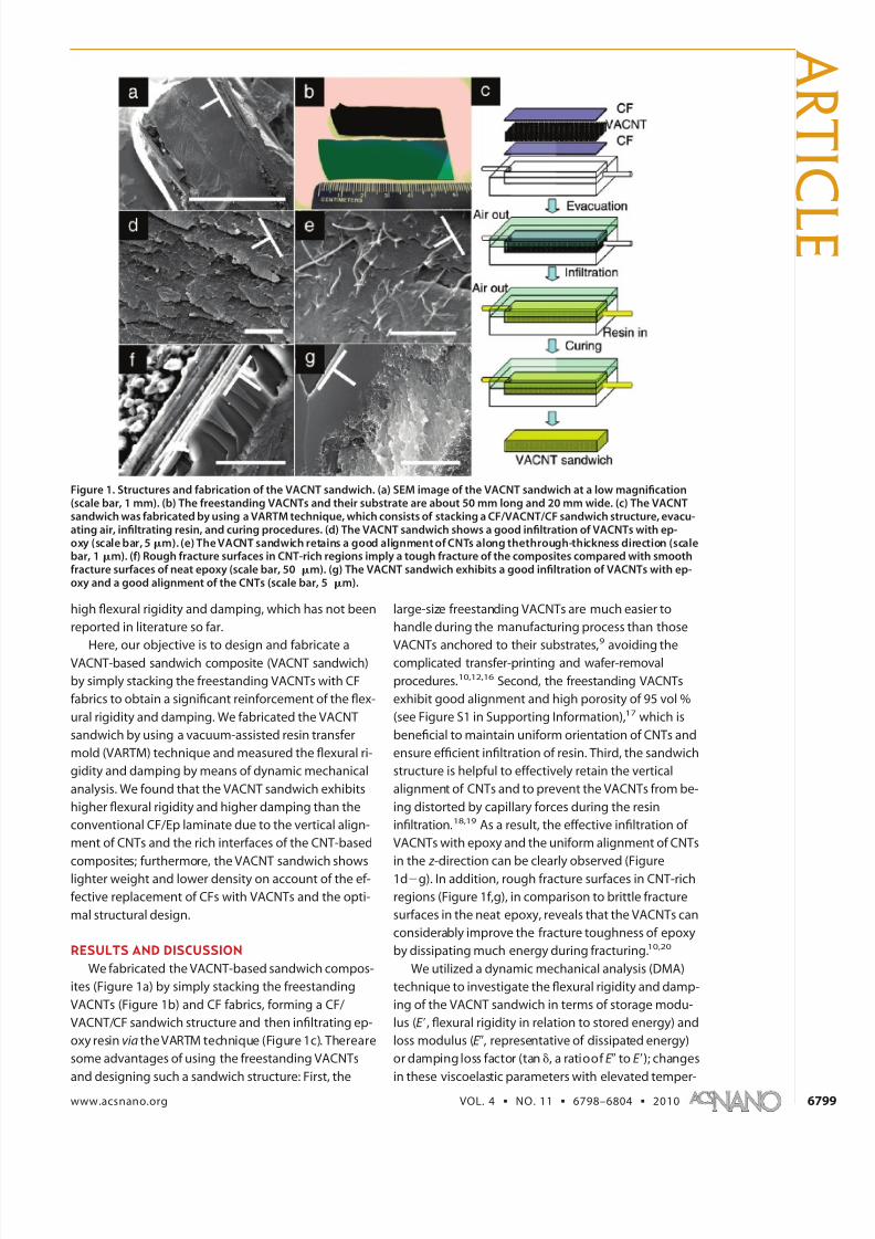
We fabricated the VACNT-based sandwich compos-
ites (Figure 1a) by simply stacking the freestanding
VACNTs (Figure 1b) and CF fabrics, forming a CF/
VACNT/CF sandwich structure and then infiltrating ep-
oxy resin via the VARTM technique (Figure 1c). Thereare
some advantages of using the freestanding VACNTs
and designing such a sandwich structure: First, the
large-size freestanding VACNTs are much easier to
handle during the manufacturing process than those
VACNTs anchored to their substrates,
9
avoiding thecomplicated transfer-printing and wafer-removal
procedures.10,12,16 Second, the freestanding VACNTs
exhibit good alignment and high porosity of 95 vol %
(see Figure S1 in Supporting Information),17 which is
beneficial to maintain uniform orientation of CNTs and
ensure efficient infiltration of resin. Third, the sandwich
structure is helpful to effectively retain the vertical
alignment of CNTs and to prevent the VACNTs from be-
ing distorted by capillary forces during the resin
infiltration.18,19 As a result, the effective infiltration of
VACNTs with epoxy and the uniform alignment of CNTs
in the z -direction can be clearly observed (Figure
1dg). In addition, rough fracture surfaces in CNT-rich
regions (Figure 1f,g), in comparison to brittle fracture
surfaces in the neat epoxy, reveals that the VACNTs can
considerably improve the fracture toughness of epoxy
by dissipating much energy during fracturing.10,20
We utilized a dynamic mechanical analysis (DMA)
technique to investigate the flexural rigidity and damp-
ing of the VACNT sandwich in terms of storage modu-
lus (E =, flexural rigidity in relation to stored energy) and
loss modulus (E , representative of dissipated energy)
or damping loss factor (tan , a ratioof E to E =); changes
in these viscoelastic parameters with elevated temper-
Figure 1. Structures and fabrication of the VACNT sandwich. (a) SEM image of the VACNT sandwich at a low magnification(scale bar, 1 mm). (b) The freestanding VACNTs and their substrate are about 50 mm long and 20 mm wide. (c) The VACNTsandwich was fabricated by using a VARTM technique, which consists of stacking a CF/VACNT/CF sandwich structure, evacu-ating air, infiltrating resin, and curing procedures. (d) The VACNT sandwich shows a good infiltration of VACNTs with ep-oxy (scale bar, 5m). (e) The VACNT sandwich retains a good alignment of CNTs along thethrough-thickness direction (scalebar, 1 m). (f) Rough fracture surfaces in CNT-rich regions imply a tough fracture of the composites compared with smoothfracture surfaces of neat epoxy (scale bar, 50 m). (g) The VACNT sandwich exhibits a good infiltration of VACNTs with ep-oxy and a good alignment of the CNTs (scale bar, 5 m).
A R T I C
L E
www.acsnano.org VOL. 4 ▪ NO. 11 ▪ 6798–6804 ▪ 2010 6799
7/31/2019 Design and Fabrication of Cnt Sandwhich
http://slidepdf.com/reader/full/design-and-fabrication-of-cnt-sandwhich 3/7
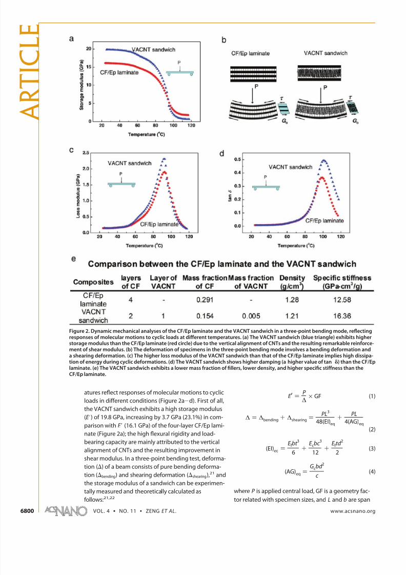
atures reflect responses of molecular motions to cyclic
loads in different conditions (Figure 2ad). First of all,the VACNT sandwich exhibits a high storage modulus
(E =) of 19.8 GPa, increasing by 3.7 GPa (23.1%) in com-
parison with E = (16.1 GPa) of the four-layer CF/Ep lami-
nate (Figure 2a); the high flexural rigidity and load-
bearing capacity are mainly attributed to the vertical
alignment of CNTs and the resulting improvement in
shear modulus. In a three-point bending test, deforma-
tion () of a beam consists of pure bending deforma-
tion (bending) and shearing deformation (shearing),21 and
the storage modulus of a sandwich can be experimen-
tally measured and theoretically calculated as
follows:21,22where P is applied central load, GF is a geometry fac-
tor related with specimen sizes, and L and b are span
Figure 2. Dynamic mechanical analyses of the CF/Ep laminate and the VACNT sandwich in a three-point bending mode, reflectingresponses of molecular motions to cyclic loads at different temperatures. (a) The VACNT sandwich (blue triangle) exhibits higherstorage modulus than the CF/Ep laminate (red circle) due to the vertical alignment of CNTs and the resulting remarkable reinforce-ment of shear modulus. (b) The deformation of specimens in the three-point bending mode involves a bending deformation anda shearing deformation. (c) The higher loss modulus of the VACNT sandwich than that of the CF/Ep laminate implies high dissipa-tion of energy during cyclic deformations. (d) The VACNT sandwich shows higher damping (a higher value of tan ) than the CF/Eplaminate. (e) The VACNT sandwich exhibits a lower mass fraction of fillers, lower density, and higher specific stiffness than theCF/Ep laminate.
E )P
∆× GF (1)
∆ ) ∆bending + ∆shearing )PL3
48(EI)eq
+PL
4(AG)eq
(2)
(EI)eq )E f bt
3
6+
E cbc 3
12+
E f td 2
2(3)
(AG)eq )
Gcbd 2
c (4)
A R
T I C L E
VOL. 4 ▪ NO. 11 ▪ ZENG ET AL. www.acsnano.org6800
7/31/2019 Design and Fabrication of Cnt Sandwhich
http://slidepdf.com/reader/full/design-and-fabrication-of-cnt-sandwhich 4/7
length and specimen width, respectively; (EI)eq and
(AG)eq are equivalent flexural rigidity and equivalent
shear rigidity; t , c , and d are thicknesses of the face
sheet, core, and sandwich, respectively; E f and E c are
elastic modulus of the face sheet and that of the core,
and Gc is shear modulus of the core. For the conven-
ience of comparison, the CF/Ep laminate investigated
can be considered as a CF/Ep-core sandwich, which has
the same CF/Ep face sheets (E f ) and geometric sizes (b,
t , c , and d ) as the VACNT sandwich; therefore, the differ-
ence in storage modulus (E =) between the CF/Ep lami-
nate and the VACNT sandwich only depends on the val-
ues of E c and Gc. It is worth mentioning that the
VACNT/Ep core generally has a lower elastic modulus
(E c) than the CF/Ep core due to the waviness of CNTs
and low CNT content (less than 0.5 wt %),5,17 but the
VACNT/Ep core exhibits a much higher shear modulus
(Gc) than the CF/Ep core due to the vertical alignment of
CNTs. According to mechanics of composites, the value
of the shear modulus strongly depends on the fiber ori-
entation; the composites with the fiber orientation inthe z -direction have much higher shear modulus than
those in the in-plane direction.23,24 In the case of the
VACNT/Ep core, the fiber orientation is nearly vertical
to the direction of shear stress (; Figure 2b), while the
case is just opposite for the CF/Ep core; as a result, the
VACNT/Ep core exhibits much higher value of Gc than
the CF/Ep core. In our work, the VACNTs play an impor-
tant role in integrating and anchoring two CF/Ep lay-
ers, significantly increasing the shear modulus, effec-
tively transferring shear stress in the through-thickness
direction, and resulting in a high flexural rigidity, which
is consistent with the CNT reinforcement of interlami-nar shear strength of laminate composites.12,25 More-
over, it is notable that the high flexural rigidity for the
VACNT sandwich generally implies a high resistance to
delamination failure which plagues conventional lami-
nate composites.
The VACNT sandwich shows higher values of loss
modulus (E ==) and tan than the CF/Ep laminate (Fig-
ure 2c,d); the high damping is closely associated with
the vertical alignment of CNTs, rich interfacial areas
of the nanocomposites, and high thermal conductivity
of the VACNTs. First, the VACNT/Ep core exhibits high
anisotropy due to the vertical alignment of CNTs, andits elastic modulus in the in-plane direction is much
lower than that in the z -direction.17 Correspondingly,
the interfacial slip in the in-plane direction is rather eas-
ily triggered under compressive and tensile loads dur-
ing the three-point bending deformation (Figure 2b)
and then results in much higher dissipation of
energy.15,26 Second, the VACNT sandwich has much
more interfacial areas than the CF/Ep laminate on ac-
count of the small diameter and large specific surface
area of the CNTs, and consequently, much interfacial
slip occurs during cyclic deformations and leads to the
high energy dissipation and loss modulus;2729 such a
phenomenon can also be observed by comparing the
CF/Ep laminate with the neat epoxy (see Figure S2 in
Supporting Information). Third, the high thermal con-
ductivity of the VACNTs can also accelerate the dissipa-
tion of energy as heat and cause a damping
improvement.16,30,31 Therefore, the high dissipation of
energy and the high damping of the VACNT sandwich is
mainly attributed to the vertical alignment of CNTs,
the rich interfacial areas of the CNT-based composites,
and the high thermal conductivity of CNTs.
Besides the high flexural rigidity and damping, the
VACNT sandwich exhibits a lower density and higher
specific stiffness (a ratio of flexural rigidity to density)
than the CF/Ep laminate (Figure 2e). It is worth men-
tioning that the VACNT sandwich has only half the mass
fraction of fillers of the CF/Ep laminate, but it exhibits
much higher flexural rigidity and damping, implying
that the VACNTs can not only partially replace CF fab-
rics and reduce weight, but also further improve the dy-
namic mechanical properties as a result of the optimal
design of composite structures. Owing to low densityand high stiffness and damping, the VACNT sandwiches
can be utilized as competitive candidates for high-
performance composites in aerospace and transporta-
tion fields.
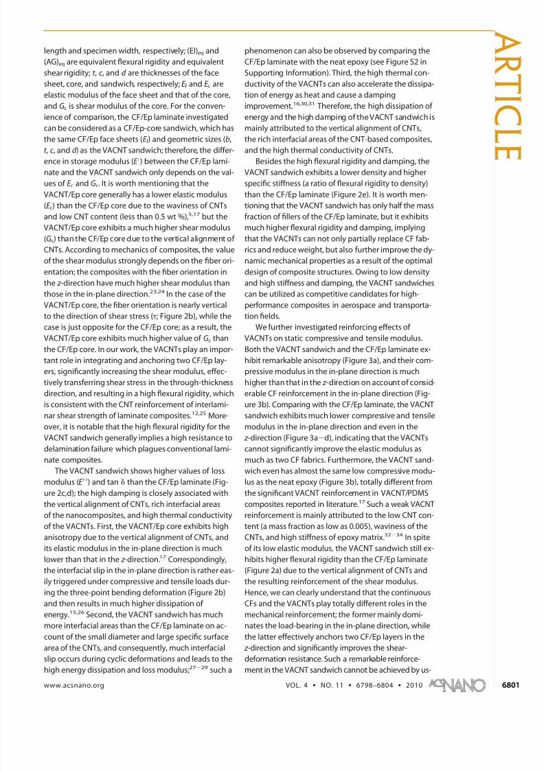
We further investigated reinforcing effects of
VACNTs on static compressive and tensile modulus.
Both the VACNT sandwich and the CF/Ep laminate ex-
hibit remarkable anisotropy (Figure 3a), and their com-
pressive modulus in the in-plane direction is much
higher than that in the z -direction on account of consid-
erable CF reinforcement in the in-plane direction (Fig-
ure 3b). Comparing with the CF/Ep laminate, the VACNTsandwich exhibits much lower compressive and tensile
modulus in the in-plane direction and even in the
z -direction (Figure 3ad), indicating that the VACNTs
cannot significantly improve the elastic modulus as
much as two CF fabrics. Furthermore, the VACNT sand-
wich even has almost the same low compressive modu-
lus as the neat epoxy (Figure 3b), totally different from
the significant VACNT reinforcement in VACNT/PDMS
composites reported in literature.17 Such a weak VACNT
reinforcement is mainly attributed to the low CNT con-
tent (a mass fraction as low as 0.005), waviness of the
CNTs, and high stiffness of epoxy matrix.3234
In spiteof its low elastic modulus, the VACNT sandwich still ex-
hibits higher flexural rigidity than the CF/Ep laminate
(Figure 2a) due to the vertical alignment of CNTs and
the resulting reinforcement of the shear modulus.
Hence, we can clearly understand that the continuous
CFs and the VACNTs play totally different roles in the
mechanical reinforcement; the former mainly domi-
nates the load-bearing in the in-plane direction, while
the latter effectively anchors two CF/Ep layers in the
z -direction and significantly improves the shear-
deformation resistance. Such a remarkable reinforce-
ment in the VACNT sandwich cannot be achieved by us-
A R T I C
L E
www.acsnano.org VOL. 4 ▪ NO. 11 ▪ 6798–6804 ▪ 2010 6801
7/31/2019 Design and Fabrication of Cnt Sandwhich
http://slidepdf.com/reader/full/design-and-fabrication-of-cnt-sandwhich 5/7
ing conventional CF fabrics and random CNTs separately.
Therefore, combining CF fabrics with VACNTs via an opti-
mal design is an effective method for taking full advan-
tages of both two components to obtain high-
performance composites.
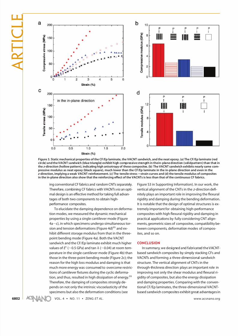
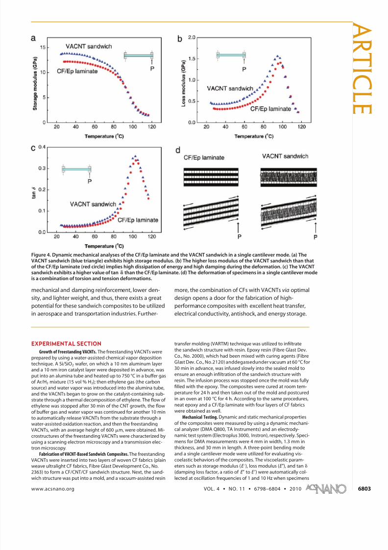
To elucidate the damping dependence on deforma-
tion modes, we measured the dynamic mechanical
properties by using a single cantilever mode (Figure
4ac), in which specimens undergo simultaneous tor-
sion and tension deformations (Figure 4d)35 and ex-
hibit different storage modulus from that in the three-
point bending mode (Figure 4a). Both the VACNT
sandwich and the CF/Ep laminate exhibit much higher
values of E (0.5 GPa) and tan (0.04) at room tem-
perature in the single cantilever mode (Figure 4b) than
those in the three-point bending mode (Figure 2c); the
reason for the high loss modulus and damping is that
much more energy was consumed to overcome restric-
tions of cantilever fixtures during the cyclic deforma-
tion, and thus, resulted in high dissipation of energy.35
Therefore, the damping of composites strongly de-
pends on not only the intrinsic viscoelasticity of the
specimens but also the deformation conditions (see
Figure S3 in Supporting Information). In our work, the
vertical alignment of the CNTs in the z -direction defi-
nitely plays an important role in improving the flexural
rigidity and damping during the bending deformation.
It is notable that the design of optimal structures is ex-
tremely important for obtaining high-performance
composites with high flexural rigidity and damping in
practical applications by fully considering CNT align-
ments, geometric sizes of composites, compatibility be-
tween components, deformation modes of compos-
ites, and so on.
CONCLUSION
In summary, we designed and fabricated the VACNT-
based sandwich composites by simply stacking CFs and
VACNTs and forming a three-dimensional sandwich
structure. The vertical alignment of CNTs in the
through-thickness direction plays an important role in
improving not only the shear modulus and flexural ri-
gidity of composites, but also the energy dissipation
and damping properties. Comparing with the conven-
tional CF/Ep laminates, the three-dimensional VACNT-
based sandwich composites exhibit great advantages in
Figure 3. Static mechanical properties of the CF/Ep laminate, the VACNT sandwich, and the neat epoxy. (a) The CF/Ep laminate (redcircle) and the VACNT sandwich (blue triangle) exhibit high compressive strength in thein-plane direction (solidpattern) than that inthe z -direction (hollow pattern), indicating high anisotropy of these composites. (b) The VACNT sandwich exhibits nearly same com-pressive modulus as neat epoxy (black square), much lower than the CF/Ep laminate in the in-plane direction and even in the z -direction, implying a weak VACNT-reinforcement. (c) The tensile stressstrain curves and (d) the tensile modulus of composites
in the in-plane direction also show that the reinforcing effect of the VACNTs is less than that of the continuous CF fabrics.
A R
T I C L E
VOL. 4 ▪ NO. 11 ▪ ZENG ET AL. www.acsnano.org6802
7/31/2019 Design and Fabrication of Cnt Sandwhich
http://slidepdf.com/reader/full/design-and-fabrication-of-cnt-sandwhich 6/7
mechanical and damping reinforcement, lower den-sity, and lighter weight, and thus, there exists a great
potential for these sandwich composites to be utilized
in aerospace and transportation industries. Further-
more, the combination of CFs with VACNTs via optimaldesign opens a door for the fabrication of high-
performance composites with excellent heat transfer,
electrical conductivity, antishock, and energy storage.
EXPERIMENTAL SECTION
Growth of Freestanding VACNTs. The freestanding VACNTs were
prepared by using a water-assisted chemical vapor deposition
technique. A Si/SiO2 wafer, on which a 10 nm aluminum layer
and a 10 nm iron catalyst layer were deposited in advance, was
put into an alumina tube and heated up to 750 °C in a buffer gas
of Ar/H2 mixture (15 vol % H2); then ethylene gas (the carbon
source) and water vapor was introduced into the alumina tube,
and the VACNTs began to grow on the catalyst-containing sub-
strate through a thermal decomposition of ethylene. The flow of
ethylene was stopped after 30 min of the CNT growth, the flow
of buffer gas and water vapor was continued for another 10 min
to automatically release VACNTs from the substrate through a
water-assisted oxidation reaction, and then the freestanding
VACNTs, with an average height of 600 m, were obtained. Mi-
crostructures of the freestanding VACNTs were characterized by
using a scanning electron microscopy and a transmission elec-
tron microscopy.
Fabrication of VACNT-Based Sandwich Composites. The freestanding
VACNTs were inserted into two layers of woven CF fabrics (plain
weave ultralight CF fabrics, Fibre Glast Development Co., No.
2363) to form a CF/CNT/CF sandwich structure. Next, the sand-
wich structure was put into a mold, and a vacuum-assisted resin
transfer molding (VARTM) technique was utilized to infiltrate
the sandwich structure with resin. Epoxy resin (Fibre Glast Dev.
Co., No. 2000), which had been mixed with curing agents (Fibre
Glast Dev. Co., No.2120) anddegassedunder vacuum at 60 °C for
30 min in advance, was infused slowly into the sealed mold to
ensure an enough infiltration of the sandwich structure with
resin. The infusion process was stopped once the mold was fully
filled with the epoxy. The composites were cured at room tem-perature for 24 h and then taken out of the mold and postcured
in an oven at 100 °C for 4 h. According to the same procedures,
neat epoxy and a CF/Ep laminate with four layers of CF fabrics
were obtained as well.
Mechanical Testing. Dynamic and static mechanical properties
of the composites were measured by using a dynamic mechani-
cal analyzer (DMA Q800, TA Instruments) and an electrody-
namic test system (Electroplus 3000, Instron), respectively. Speci-
mens for DMA measurements were 4 mm in width, 1.3 mm in
thickness, and 30 mm in length. A three-point bending mode
and a single cantilever mode were utilized for evaluating vis-
coelastic behaviors of the composites. The viscoelastic param-
eters such as storage modulus (E =), loss modulus (E ), and tan
(damping loss factor, a ratio of E to E =) were automatically col-
lected at oscillation frequencies of 1 and 10 Hz when specimens
Figure 4. Dynamic mechanical analyses of the CF/Ep laminate and the VACNT sandwich in a single cantilever mode. (a) TheVACNT sandwich (blue triangle) exhibits high storage modulus. (b) The higher loss modulus of the VACNT sandwich than thatof the CF/Ep laminate (red circle) implies high dissipation of energy and high damping during the deformation. (c) The VACNTsandwich exhibits a higher value of tan than the CF/Ep laminate. (d) The deformation of specimens in a single cantilever modeis a combination of torsion and tension deformations.
A R T I C
L E
www.acsnano.org VOL. 4 ▪ NO. 11 ▪ 6798–6804 ▪ 2010 6803
7/31/2019 Design and Fabrication of Cnt Sandwhich
http://slidepdf.com/reader/full/design-and-fabrication-of-cnt-sandwhich 7/7
were heated up from room temperature to 120 °C at a constantheating rate of 2 °C · min1. It is worth mentioning that thedamping measurement by using DMA method here is some-what different from that by using conventional mechanical im-pedance method, but analyses from both methods are consis-
tent in describing the viscoelastic behaviors of the composites,that is, the response of molecular motions to cyclic loads in dif-ferent conditions. Dumbbell-shaped and cubic specimens wereprepared for tensile and compressive measurements, and thetensile and compressive rates were 1 and 0.5 mm · min1,
respectively.
Acknowledgment. The authors thank Dr. L. Song, Dr. L. M.Reddy, C. Rong, and Prof. A. Srivastava for many helpful discus-sions. Y.Z. acknowledges the support from National Natural Sci-ence Foundation of China under Grant 90606008 and Liang Edu-cation Department of China under Grant 220589 and LS2010128.
Supporting Information Available: SEMand TEM imagesshow-
ing the microstructures of the freestanding VACNTs and vis-coelasticity of composites in three-point bending and single can-tilever modes. This material is available free of charge via theInternet at http://pubs.acs.org.
REFERENCES AND NOTES
1. Endo, M.; Strano, M. S.; Ajayan, P. M. Potential Applications
of Carbon Nanotubes. In Carbon Nanotubes; Jorio, A.,Dresselhaus, G., Dresselhaus, M. S., Eds.; Springer: Berlin,2008; Vol. 111, pp 1361.
2. Ajayan, P. M.; Tour, J. M. Nanotube Composites. Nature2007, 447 , 1066–1068.
3. Ajayan, P. M.; Charlier, J. C.; Rinzler, A. G. Carbon
Nanotubes: From Macromolecules to Nanotechnology.
Proc. Natl. Acad. Sci. U.S.A. 1999, 96, 14199–14200.4. Coleman, J. N.; Khan, U.; Blau, W. J.; Gun’ko, Y. K. Small But
Strong: A Review of the Mechanical Properties of CarbonNanotube-Polymer Composites. Carbon 2006, 44,1624–1652.
5. Njuguna, J.; Pielichowski, K.; Alcock, J. R. Epoxy-Based FibreReinforced Nanocomposites. Adv. Eng. Mater. 2007, 9,835–847.
6. Chou, T. W.; Gao, L. M.; Thostenson, E. T.; Zhang, Z. G.;
Byun, J. H. An Assessment of the Science and Technologyof Carbon Nanotube-Based Fibers and Composites.
Compos. Sci. Technol. 2010, 70, 1–19.7. Dzenis, Y. Materials Science O Structural Nanocomposites.
Science2008, 319, 419–420.8. Wicks, S. S.; de Villoria, R. G.; Wardle, B. L. Interlaminar and
Intralaminar Reinforcement of Composite Laminates withAligned Carbon Nanotubes. Compos. Sci. Technol. 2010, 70,
20–28.9. Veedu, V. P.; Cao, A. Y.; Li, X. S.; Ma, K. G.; Soldano, C.; Kar,
S.; Ajayan, P. M.; Ghasemi-Nejhad, M. N. MultifunctionalComposites Using Reinforced Laminae with Carbon-Nanotube Forests. Nat. Mater. 2006, 5, 457–462.
10. Garcia, E. J.; Wardle, B. L.; Hart, A. J. Joining PrepregComposite Interfaces with Aligned Carbon Nanotubes.
Composites, Part A 2008, 39, 1065–1070.
11. Blanco, J.; Garcia, E. J.; De Villoria, R. G.; Wardle, B. L.Limiting Mechanisms of Mode I Interlaminar Tougheningof Composites Reinforced with Aligned CarbonNanotubes. J. Compos. Mater. 2009, 43, 825–841.
12. Abot, J. L.; Song, Y.; Schulz, M. J.; Shanov, V. N. NovelCarbon Nanotube Array-Reinforced Laminated CompositeMaterials with Higher Interlaminar Elastic Properties.
Compos. Sci. Technol. 2008, 68, 2755–2760.13. Finegan, I. C.; Gibson, R. F. Recent Research on
Enhancement of Damping in Polymer Composites.
Compos. Struct. 1999, 44, 89–98.14. Gibson, R. F.; Ayorinde, E. O.; Wen, Y. F. Vibrations of
Carbon Nanotubes and Their Composites: A Review.
Compos. Sci. Technol. 2007, 67 , 1–28.15. Sun, C. T.; Gibson, R. F.; Chaturvedi, S. K. Internal Material
Damping of Polymer Matrix Composites under Off-AxisLoading. J. Mater. Sci. 1985, 20, 2575–2585.
16. Huang, H.; Liu, C. H.; Wu, Y.; Fan, S. S. Aligned CarbonNanotube Composite Films for Thermal Management. Adv.Mater. 2005, 17 , 1652–1656.
17. Ci, L.; Suhr, J.; Pushparaj, V.; Zhang, X.; Ajayan, P. M.Continuous Carbon Nanotube Reinforced Composites.
Nano Lett. 2008, 8, 2762–2766.18. Chakrapani, N.; Wei, B. Q.; Carrillo, A.; Ajayan, P. M.; Kane,
R. S. Capillarity-Driven Assembly of Two-DimensionalCellular Carbon Nanotube Foams. Proc. Natl. Acad. Sci.U.S.A. 2004, 101, 4009–4012.
19. Garcı́a, E. J.; Hart, A. J.; Wardle, B. L.; Slocum, A. H.Fabrication of Composite Microstructures by Capillarity-Driven Wetting of Aligned Carbon Nanotubes withPolymers. Nanotechnology 2007, 18, 165602.
20. Srivastava, I.; Koratkar, N. Fatigue and Fracture Toughnessof Epoxy Nanocomposites. JOM 2010, 62, 50–57.
21. Davies, J. M. Lightweight Sandwich Construction; Blackwell:Oxford, 2001; pp 193226.
22. Sharma, R. S.; Raghupathy, V. P. A Holistic Approach toStatic Design of Sandwich Beams with Foam Cores. J.Sandwich Struct. Mater. 2008, 10, 429–441.
23. Jones, R. M. Mechanics of Composite Materials, 2nd ed.; Taylor & Francis: Philadelphia, 1999; pp 4578.
24. Seidel, G. D.; Lagoudas, D. C. Micromechanical Analysis of the Effective Elastic Properties of Carbon NanotubeReinforced Composites. Mech. Mater. 2006, 38, 884–907.
25. Fan, Z. H.; Santare, M. H.; Advani, S. G. Interlaminar ShearStrength of Glass Fiber Reinforced Epoxy CompositesEnhanced with Multi-Walled Carbon Nanotubes.
Composites, Part A 2008, 39, 540–554.26. Finegan, I. C.; Tibbetts, G. G.; Gibson, R. F. Modeling and
Characterization of Damping in CarbonNanofiber/Polypropylene Composites. Compos. Sci.Technol. 2003, 63, 1629–1635.
27. Suhr, J.; Koratkar, N.; Keblinski, P.; Ajayan, P. Viscoelasticityin Carbon Nanotube Composites. Nat. Mater. 2005, 4,134–137.
28. Suhr, J.; Koratkar, N. A. Energy Dissipation in CarbonNanotube Composites: A Review. J. Mater. Sci. 2008, 43,4370–4382.
29. Sun, L. Y.; Gibson, R. F.; Gordaninejad, F.; Suhr, J. EnergyAbsorption Capability of Nanocomposites: A Review.
Compos. Sci. Technol. 2009, 69, 2392–2409.
30. Salehi-Khojin, A.; Jana, S.; Zhong, W. H. Thermal-Mechanical Properties of a Graphitic-NanofibersReinforced Epoxy. J. Nanosci. Nanotechnol. 2007, 7 ,898–906.
31. Shaikh, S.; Li, L.; Lafdi, K.; Huie, J. Thermal Conductivity of an Aligned Carbon Nanotube Array. Carbon 2007, 45,2608–2613.
32. Cebeci, H.; de Villoria, R. G.; Hart, A. J.; Wardle, B. L.Multifunctional Properties of High Volume FractionAligned Carbon Nanotube Polymer Composites withControlled Morphology. Compos. Sci. Technol. 2009, 69,2649–2656.
33. Li, C. Y.; Chou, T. W. Failure of Carbon Nanotube/PolymerComposites and the Effect of Nanotube Waviness.
Composites, Part A 2009, 40, 1580–1586.34. Ci, L.; Bai, J. The Reinforcement Role of Carbon Nanotubes
in Epoxy Composites with Different Matrix Stiffness.Compos. Sci. Technol. 2006, 66, 599–603.
35. Menard, K. P. Dynamic Mechanical Analysis: A Practical Introduction; CRC Press: Boca Raton, 1999; pp 7282.
A R
T I C L E
VOL. 4 ▪ NO. 11 ▪ ZENG ET AL. www.acsnano.org6804