Embed Size (px)
Citation preview

Design and Development of
Sodium Submersible Electromagnetic Pump
for High Temperature Application
By
B.K. NASHINE (ENGG02200804010)
Indira Gandhi Centre for Atomic Research
Kalpakkam
A thesis submitted to the
Board of Studies in Engineering Sciences
In partial fulfillment of requirements
for the Degree of
DOCTOR OF PHILOSOPHY
of
Homi Bhabha National Institute
April, 2015


Dedicated to my parents,
wife and children


CONTENTS Page No.
Synopsis i
List of Figures iii
List of Tables vi
Glossary vii
List of Symbols viii
CHAPTER 1
INTRODUCTION & REVIEW OF LITERATURE
1.1 Indian Nuclear Power Program 1
1.2 Description of Prototype Fast Breeder Reactor (PFBR)
1.3 Research Objective
1.4 Motivation for the Present Study
1.5 Brief Description of Electromagnetic Pumps
1.6 Status of EM Pumps - a review
4
6
7
8
13
1.7 Knowledge Gained from the Literature Survey
1.8 Organization of Thesis
25
26
CHAPTER 2
DEVELOPMENT OF MATHEMATICAL MODEL FOR
ANNULAR LINEAR INDUCTION PUMP (ALIP)
2.1 Introduction
2.2 Design Methodology of Annular Linear Induction Pump
2.3 Working Principle and Equivalent Circuit of ALIP
2.4 Estimation of Equivalent Circuit Parameters – A First Principle
Approach
2.5 Summary
27
27
27
32
41
CHAPTER 3
SUBMERSIBLE ANNULAR LINEAR INDUCTION PUMP DESIGN
AND ANALYSIS
3.1 Design Requirement 42

3.2 Design of Submersible Annular Linear Induction Pump 42
3.3 Dimensions of Designed ALIP 43
3.4 Simulation of Submersible ALIP 45
3.5 Effect of Stainless Steel Sheath of Winding and Winding Retainer Plate
on ALIP and Derivation of Modified Equivalent Circuit for MI Cable
Wound ALIP
57
3.6 Theoretical Characteristics of Developed Submersible ALIP 62
3.7 Calulation of Magnetic Reynolds Number for the developed
Submersible ALIP
63
3.8 Summary 64
CHAPTER 4
ANNULAR LINEAR INDUCTION PUMP DEVELOPMENT &
MANUFACTURING
4.1 Development of Induction Motor with MI Cable Winding (Stage-1) 65
4.2 Design of Induction Motor with class H insulation 65
4.3 Design of High Temperature Induction Motor with Mineral Insulated
Cable Winding
70
4.4. Demonstration of Use of MI Cable for Rewinding of conventional
Induction Motor
80
4.5 Development and Testing of Mineral Insulated Stainless Steel Sheathed
Cable for ALIP (Stage II)
81
4.6 Manufacture of Submersible Annular Linear Induction Pump (Stage III) 82
4.7 Summary 84
CHAPTER 5
PERFORMANCE EVALUATION OF SODIUM SUBMERSIBLE ALIP
5.1 Introduction 85
5.2 Description of Sodium Test Facility 85
5.3 Cover Gas System 86
5.4 Sodium Pressure Measurement Methodology 86
5.5 Power Supply Scheme for Testing of Submersible ALIP 87
5.6 Preheating System 87
5.7 Instrumentation and Control 88
5.8 Control Logics 89
5.9 Performance Evaluation of Sodium Submersible ALIP 90
5.10 Testing Procedure 91
5.11 Test Results 92
5.12 Discussion on Test Results 93
5.13 Summary 95
CHAPTER 6
SUMMARY AND FUTURE PROSPECTS
6.1 Summary 110
6.2 Future Research Prospects 113
APPENDIX-A
APPENDIX-B
REFERENCES
115
126
130
PUBLICATIONS 134
i
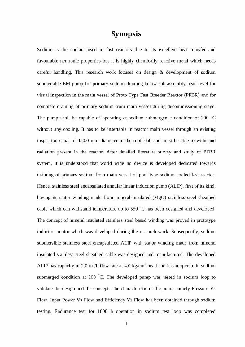
Synopsis
Sodium is the coolant used in fast reactors due to its excellent heat transfer and
favourable neutronic properties but it is highly chemically reactive metal which needs
careful handling. This research work focuses on design & development of sodium
submersible EM pump for primary sodium draining below sub-assembly head level for
visual inspection in the main vessel of Proto Type Fast Breeder Reactor (PFBR) and for
complete draining of primary sodium from main vessel during decommissioning stage.
The pump shall be capable of operating at sodium submergence condition of 200 0C
without any cooling. It has to be insertable in reactor main vessel through an existing
inspection canal of 450.0 mm diameter in the roof slab and must be able to withstand
radiation present in the reactor. After detailed literature survey and study of PFBR
system, it is understood that world wide no device is developed dedicated towards
draining of primary sodium from main vessel of pool type sodium cooled fast reactor.
Hence, stainless steel encapsulated annular linear induction pump (ALIP), first of its kind,
having its stator winding made from mineral insulated (MgO) stainless steel sheathed
cable which can withstand temperature up to 550 0C has been designed and developed.
The concept of mineral insulated stainless steel based winding was proved in prototype
induction motor which was developed during the research work. Subsequently, sodium
submersible stainless steel encapsulated ALIP with stator winding made from mineral
insulated stainless steel sheathed cable was designed and manufactured. The developed
ALIP has capacity of 2.0 m3/h flow rate at 4.0 kg/cm
2 head and it can operate in sodium
submerged condition at 200 °C. The developed pump was tested in sodium loop to
validate the design and the concept. The characteristic of the pump namely Pressure Vs
Flow, Input Power Vs Flow and Efficiency Vs Flow has been obtained through sodium
testing. Endurance test for 1000 h operation in sodium test loop was completed
ii
successfully. The ALIP has worked without cavitation at 0.3 kg/cm2 (abs) pressure at
inlet. The overstress test at 300 °C successfully also confirmed the robustness of the new
design. The pump has not shown any flow instability. The pump was tested sodium
submerged condition at temperature of 250 oC to 500
oC for 2000 h. The outcome of
research is mainly technology demonstration of new concept and design for sodium
submersible annular linear induction pump. The research work has also brought out
evolution of new equivalent circuit for the developed annular linear induction pump to
take care of effect of eddy current in the mineral insulated SS sheathed cable winding of
the pump, which has not been reported in open literature. The research work has also
opened up new avenues for further research in ALIP area such as research for accurate
analysis of eddy current loss in mineral insulated stainless steel cable used in ALIP and
its effect on performance of ALIP, optimization of design, study towards flow instability
and use of VFD for ALIP operation. The concept has also opened up path for
development of fire survival induction motor which can be used in high temperature
application as well as fire fighting domain. Research to develop model to take account of
stainless steel sheath in winding is also one of the potential area.

iii
List of Figures
Figure No. Caption Page No.
Fig.1.1 PFBR Reactor assembly 4
Fig.1.2 PFBR Flow Sheet 5
Fig.1.3 Broad classification of the electromagnetic pumps 9
Fig 1.4 Schematic of a DC conduction pump 10
Fig.1.5 Schematic of FLIP 12
Fig.1.6 General assembly and principle of an ALIP 13
Fig.2.1 Schematic construction and working principle of ALIP 28
Fig.2.2 Equivalent circuit of ALIP 29
Fig.2.3 Definition of parameters related to coils and slots 30
Fig.2.4 Cross-section view of ALIP along with definition of various
parameters
30
Fig.2.5 Different leakage fluxes of primary winding 33
Fig.2.6 Non-magnetic jacket over central core 37
Fig.2.7 Schematic of annular gap D1 38
Fig.3.1 Flow chart for ALIP design calculations 43
Fig.3.2 General assembly of submersible ALIP 44
Fig.3.3 Simulation model in COMSOL 46
Fig.3.4 Simulation model of ALIP 49
Fig.3.5 Mesh used in simulation 50
Fig.3.6 Flux density at 2.0 m3/h flow 50
Fig.3.7 Magnitude of magnetic flux density in sodium duct at
2.0 m3/h
51
Fig.3.8 Variation of radial component of magnetic flux density in
duct
51
Fig.3.9 Contour plot of radial component of magnetic flux density 52
Fig.3.10 Arrow plot depicting the magnetic flux density lines 53
Fig.3.11 Model predicted current density in sodium duct 53
Fig.3.12 Volume force in sodium duct at 2.0 m3/h 54
Fig.3.13 Pressure development in sodium duct at 2.0 m3/h 55
Fig.3.14 Variation in developed pressure with flow 55

iv
Fig. 3.15 Comparison of theoretical developed pressure by COMSOL
and equivalent circuit model
57
Fig. 3.16 Winding arrangement in the slot 61
Fig. 3.17 Modified equivalent circuit of ALIP for taking into account
the losses taking place in SS sheath of MI cable and in SS
retainer plates
61
Fig. 3.18 Theoretical Head Vs Flow curve at 200 º C 62
Fig. 3.19 Theoretical Input Electrical Power Vs Flow at 200 ºC 62
Fig. 3.20 Theoretical Efficiency Vs Flow at 200 0C 63
Fig.4.1 Cross sectional view of stator 66
Fig.4.2 Cross sectional view of rotor 69
Fig.4.3 Cross sectional view of rotor slot 69
Fig.4.4 Low power induction motor 70
Fig. 4.5 Test set up for induction motor 70
Fig. 4.6 Schematic of test set-up for MI cable 71
Fig. 4.7 MI Cable in wound condition over a pipe and slot
arrangement
72
Fig. 4.8 Test set up without wound condition. 72
Fig. 4.9 Thermocouple reading at 10 A 72
Fig. 4.10 Current carrying capacity of MI cable 73
Fig. 4.11 Low power induction motor with MI cable 76
Fig. 4.12 Stator of low power motor with MI cable 76
Fig. 4.13 Motor in open condition 76
Fig. 4.14 Two dimensional model of induction motor 78
Fig. 4.15 External current density in stator slot (A/mm2) 79
Fig. 4.16 Magnetic flux density plot in stator (T) 79
Fig. 4.17 Magnetic flux density plot in rotor (T) 79
Fig. 4.18 Torque - slip characteristics 80
Fig. 4.19 Surface temperature Vs time 80
Fig. 4.20 Conventional motor winding replaced with MI cable winding 81
Fig. 4.21 Cross-section of MI Cable 81
Fig.4.22 View of developed MI cable 81
Fig.4.23 MI cable winding of submersible ALIP along with fixtures 83

v
and support
Fig. 4.24 Submersible ALIP with MI Cable winding and CRGO
laminations
83
Fig. 4.25 Manufactured submersible ALIP with outer stainless steel
enclosure
84
Fig. 4.26 Photograph of manufactured submersible ALIP other view 84
Fig. 5.1 Flow sheet of BIM loop with submersible ALIP 97
Fig. 5.2 Piping for submersible ALIP testing 98
Fig. 5.3 Pressure pot with level probe details 99
Fig. 5.4 Argon cover gas header for pressure pots of ALIP testing
facility
100
Fig. 5.5 Power supply wiring diagram for submersible ALIP 101
Fig. 5.6 Control circuit wiring diagram for submersible ALIP 102
Fig. 5.7 Photograph of pump erected in BIM loop 103
Fig. 5.8 Photograph of control and instrument panel and other
electrical systems
103
Fig. 5.9 Experimental Pressure Head Vs Flow Characteristics at 200
ºC
104
Fig. 5.10 Comparison of Experimental and Theoretical Pressure Head
Vs Flow Characteristics at 200 ºC
104
Fig. 5.11 Experimental Input Electrical Power Vs Flow at 200 ºC 105
Fig. 5.12 Comparison of Experimental and Theoretical Input Electrical
Power Vs Flow at 200 ºC
105
Fig. 5.13 Experimental Efficiency Vs Flow at 200 0C 106
Fig. 5.14 Comparison of Experimental and Theoretical Efficiency Vs
Flow at 200 °C
106
Fig. 5.15 Experimental Pressure Vs Flow at 300 °C (Overstress Test) 107
Fig. 5.16
Pressure Vs Flow characteristics after endurance test of 1000
h
107
Fig. 5.17 Schematic of submersible ALIP in ICT 108
Fig. 5.18 Erection of submersible ALIP for testing in ICT 109
vi
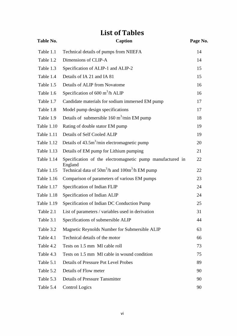
List of Tables Table No. Caption Page No.
Table 1.1 Technical details of pumps from NIIEFA 14
Table 1.2 Dimensions of CLIP-A 14
Table 1.3 Specification of ALIP-1 and ALIP-2 15
Table 1.4 Details of IA 21 and IA 81 15
Table 1.5 Details of ALIP from Novatome 16
Table 1.6 Specification of 600 m3/h ALIP 16
Table 1.7 Candidate materials for sodium immersed EM pump 17
Table 1.8 Model pump design specifications 17
Table 1.9 Details of submersible 160 m3/min EM pump 18
Table 1.10 Rating of double stator EM pump 19
Table 1.11 Details of Self Cooled ALIP 19
Table 1.12 Details of 43.5m3/min electromagnetic pump 20
Table 1.13 Details of EM pump for Lithium pumping 21
Table 1.14 Specification of the electromagnetic pump manufactured in
England
22
Table 1.15 Technical data of 50m3/h and 100m
3/h EM pump 22
Table 1.16 Comparison of parameters of various EM pumps 23
Table 1.17 Specification of Indian FLIP 24
Table 1.18 Specification of Indian ALIP 24
Table 1.19 Specification of Indian DC Conduction Pump 25
Table 2.1 List of parameters / variables used in derivation 31
Table 3.1 Specifications of submersible ALIP 44
Table 3.2 Magnetic Reynolds Number for Submersible ALIP 63
Table 4.1 Technical details of the motor 66
Table 4.2 Tests on 1.5 mm MI cable roll 73
Table 4.3 Tests on 1.5 mm MI cable in wound condition 75
Table 5.1 Details of Pressure Pot Level Probes 89
Table 5.2 Details of Flow meter 90
Table 5.3 Details of Pressure Tansmitter 90
Table 5.4 Control Logics 90

vii
Glossary
MWe Mega Watt electric
PHWR Pressurized Heavy Water Reactors
AHWR Advance Heavy Water Reactor
FBR Fast Breeder Reactors
SFR Sodium Cooled Fast Reactor
MOX Mixed Oxide
ALIP Annular Linear Induction Pump
SALIP Submersible Annular Linear Induction Pump
DCCP DC Conduction Pump
ACCP AC Conduction Pump
FLIP Flat Linear Induction Pump
MI Mineral Insulated
MgO Magnesium Oxide
FEM Finite Element Method

viii
List of Symbols
D1 Radial annular width for liquid metal passage
D2 Radial thickness of outer sodium duct
D3 Radial gap between outer sodium duct and Stator bore
D4 Thickness of stainless steel jacket surrounding the central core
D5 Total non-magnetic gap
D6 Pole Pitch
D7 Mean diameter of Annulus
D8 Bore diameter of stator surface
D9 Diameter of central core
D10 Width of stator tooth D11 Width of stator slot D12 Clearance between top of coil and top of slot
D13 Depth of coil side
D14 Slot Depth
D15 Mean length of coil turn
N1 Number of Poles produced by stator winding
N2 Number of phases
N3 Slots per pole per phase
N4 Number of slots in stator
N5 Number of teeth in stator
N7 Number of turns per coil
N8 Carter co-efficient
N9 Multiplier for D5 to account for apparent increase in D5 due to
slots
Nsc Effective number of turns in series per phase in stator R1 Stator Winding Resistance per phase (Ω / ph) Rj Equivalent resistance of jacket around central core (Ω / ph)
Rw Equivalent resistance of outer annulus wall (Ω / ph) Rf Equivalent resistance of liquid metal (Ω / ph)
Rcf Equivalent resistance of Rw, Rj and Rf in parallel X1 Stator winding Leakage Reactance per phase (Ω / ph)
Xm Magnetizing Reactance (Ω / ph)
ρCu Resistivity of copper wire
ρSS Resistivity of Stainless Steel
ρNa Resistivity of sodium Img Magnetising Current kp Pitch factor
kd Winding distribution factor p No. of pole-pairs
Vsyn Synchronous velocity of traveling magnetic field VL Velocity of liquid metal VR Relative velocity between traveling magnetic field and liquid
metal
ΔP Differential pressure developed by pump
f Stator electrical frequency (Hz) μ0 Permeability of vacuum

ix
Flux
I Current
Bm Peak value of flux density
Hm Magnetic field intensity
Fa Stator mmf
Tph Turns per phase
p Pole pairs
EA voltage induced across Xm
τ Pole pitch
U Uranium
Pu Plutonium ω
ω Angular velocity
J Current dencity
σ Electrical conductivity η Efficiency


1
CHAPTER – 1
INTRODUCTION AND REVIEW OF LITERATURE
1.1 Indian Nuclear Power Program
Nuclear energy is a viable alternative energy source to meet ever-growing demand
for energy with less impact on environment [1]. Presently, nuclear energy provides over
15% of the world’s total electricity. As of July 2014, there are around 435 nuclear
reactors in 31 countries with a total installed capacity of 3.70 GigaWattt electric (GWe).
In India, currently about 3% of total energy production is coming from nuclear energy.
When a fissile element atom is bombarded by neutron, the fissile element breaks into low
atomic mass elements and this gives approximately 200 MeV equivalent thermal energy.
If this nuclear reaction is continued, it has capability to produce 200 MeV energy per
fission continuously. Splitting of multiple atoms can produce high amount of energy
proportional to number of fissile atoms split and this is the basis of producing nuclear
energy in a nuclear reactor. U235
is naturally available fissile material while Pu239
and U233
are man made fissile materials by transmutation of U238
and Th232
respectively in a
nuclear reactor. Transmutation is a radioactive phenomenon in which bombardement of
neutrons on some element, results in conversion of element into other element. This
happens because of absorption of neutron by the element leading to increase in atomic
weight of element, hence converting the original element into other element. All the
above mentioned three fissile materials give approximately 200 MeV energy per atom
split on bombardment of neutron.
Uranium resources (~110,000 tonnes) in India are limited, which is around 2% of
world uranium resources. But India has vast resources of thorium (~ 800,000 tonnes
estimated) which is around 25% of world thorium resources. The available U235
resources can generate around 10 GWe for about 40 years according to Nuclear Power

2
Corporation of India Limited (NPCIL). According to Department of Atomic Energy
(DAE), the country can produce more than 500 GWe for 400 years using country’s
economically extractable thorium reserves. In order to exploit the nuclear fuel resources
for energy production, a sequential three-stage programme is envisaged in India based on
a closed fuel cycle, where the spent fuel of one stage is reprocessed to produce fuel for
the next stage. The first stage of Indian nuclear programme involves deployment of
Pressurized Heavy Water Reactors (PHWRs), where natural uranium (U238
+ U235
) in
oxide form is used as fuel. It produces energy and some part of U238
gets transmuted to
fissile element Pu239
[4,5].
In the second stage, Fast Breeder Reactors (FBRs) employ mixed oxide (MOX)
fuel made of Pu239
(recovered by reprocessing of spent fuel from the first stage) and
uranium. In FBRs, Pu239
undergoes fission reaction to produce energy. Further, Pu239
is
produced by transmutation of U238
present in the fuel. FBRs can produce more fuel than
they consume and hence, termed breeders. Over a period of time, plutonium inventory
can be built up by transmutation of U238
. Similarly Th232
is not a fissile element but can be
converted to a fissile material (U233
) by transmutation in FBRs. The third stage of the
programme will be based on advanced heavy water reactor in which U233
will be used as
the fuel for producing electricity and Th232
will be transmuted to obtain U233
to form a
self-sustaining series of Th232
and U233
fuelled reactors, with appropriate reprocessing
programme.
Now, India is in the second stage of the nuclear program, where sodium cooled
fast reactors are being used for power generation. The fast breeder reactor operates in fast
neutron energy spectrum where high energy fast neutrons are used for the nuclear chain
reaction. These fast neutrons bombard the fissile elements present in the fuel for
producing nuclear energy. Since the reactor has to operate in fast neuton energy spectrum,

3
the nuclear fuel (Plutonium and Uranium) are placed in a compact manner, so that fast
neutrons have to travel lesser distance without loosing much of energy for remaining in
fast spectrum energy level, before meeting fissile atoms for chain reaction. This makes
the FBR core very small but enriched with plutonium, resulting in volumetric high power
density. The coolant in the FBR should not reduce the energy of fast neutrons i.e. it
should not moderate the neutrons. The typical linear fuel power density in FBR can be of
the order of 450 W/cm. This high power density heat can be efficiently removed only by
a coolant that has very good heat transfer property. Hence in Indian FBR, sodium is used
as a coolant due to its excellent heat transfer property and favourable neutronic property
which does not moderate the neutrons. Sodium is a highly reactive element and it reacts
violently when it comes in contact with oxygen and moisture. Hence, it has to be kept
always in inert atmosphere. Proto type Fast Breeder Reactor (PFBR) uses sodium as
coolant. Sodium will be continued to be used as coolant for several other future fast
reactors [2,3,6]. Use of large amount of sodium in primary coolant system is also
advantageous from the standpoint of safety, because of high heat capacity of sodium and
natural circulation flow. Sodium has good electrical conductivity and this facilitates the
use of electromagnetic pumps for pumping sodium in fast reactors as well as in
experimental sodium facilities. In a FBR, sodium has to be pumped from cold zone to hot
zone for heat transfer. The pumping of sodium is done by centrifugal mechanical pumps
and by electromagnetic (EM) pumps. The centrifugal mechanical pumps are used in main
heat transport circuits while EM pumps are used in auxiliary purification circuits in
FBRs. EM pumps are also used for pumping sodium in experimental facilities where
various fast reactor components are tested for their performance evaluation.

4
1.2 Description of Prototype Fast Breeder Reactor (PFBR)
India is on the verge of commissioning of prototype fast breeder reactor (PFBR)
which forms the second stage of India’s nuclear program [2]. Fig.1.1 shows the PFBR
reactor assembly and Fig.1.2 shows the PFBR flow sheet. About 1200 t of primary
sodium (main coolant) is contained in the main vessel.
Fig.1.1 PFBR Reactor assembly [2]

5
Fig.1.2 PFBR Flow Sheet [2]
The nuclear fuel core, primary sodium pump, intermediate heat exchanger (IHX)
and fuel transfer machine are housed in main vessel. The secondary sodium circuit and
steam water ciruit are outside the main vessel as shown in Fig.1.2.
The main vessel is divided into two zones, namely, cold pool and hot pool. The
primary sodium pump sucks cold sodium (397 °C) from cold pool and pumps out to the
fuel core zone. The pumped cold sodium extracts heat from the fuel core and attains a
temperature of 547 °C. This hot sodium passes through the intermediate heat exchanger
(IHX) which transfers the heat to secondary sodium that is pumped out by other sodium
pump called, secondary sodium pump. The hot primary sodium, after loosing the heat in
IHX, becomes cold and comes back to the cold pool for recirculation. The secondary
sodium transfers the heat to steam-water circuit to generate the steam which rotates the
turbine and alternator for generating the electricity. The primary sodium always remains
6
in the primary sodium pool contained in the main vessel and pumped by the mechanical
sodium pump [2,3].
1.3 Research Objective
In PFBR, hot pool primary sodium is maintained at 547 °C and cold pool sodium
is maintained at 397 °C during full power operation. The primary sodium is maintained at
200 °C during fuel handling period, which is minimum temperature of sodium permitted
in PFBR. As stated earlier, primary radioactive sodium is always contained in the main
vessel through out the reactor life of 40-60 years. In case of any untoward incident,
requiring visual inspection of the fuel sub-assembly head using periscope or for reactor
decommissioning, the primary sodium has to be drained outside the main vessel to a
storage tank. Presently, there is no provision for large scale draining of primary sodium to
outside storage tank. This needs pumping device which has to be submerged in sodium
and operate at 200 °C without provision of any external cooling arrangement. The
pumping device has to be placed inside the reactor through available inspection canal of
maximum diameter of 450 mm. The pump shall be capable of operating in radiation field.
The drained sodium shall also come out through pump outlet line passing through the
inspection canal through which the pump is inserted [7]. Hence the techonological
challenges to be considered while designing the device for draining the primary sodium
from the main vessel of FBRs are:
1) operation in sodium submerged condition
2) operation to withstand sodium temperature upto 200 oC
3) operation without any external cooling
4) slender and compact construction which can be inserted inside reactor through
inspection canal of 450 mm diameter
5) operation in high radiation field present in the reactor

7
Keeping the above constraints in mind, the research objective was set to design
and develop a sodium submersible pump capable of operating in radiation field at 200 °C
sodium without any external cooling facility and with a maximum diameter of 400 mm.
Preliminary studies were carried out to finalize the option available for achieving
the above mentioned aim. The primary sodium pump, even though submerged in primary
sodium, can only circulate sodium within the main vessel and it can not drain primary
sodium out side the main vessel. Hence, existing primary sodium pump is not considered.
The draining of sodium using present purification circuit and its electromagnetic pump is
not possible because it can not drain the primary sodium upto fuel sub-assembly head
level and below. Use of small centrifugal pump which can be inserted through the
inspection canal for draining is not possible due to space constraints because it is difficult
to have the pump shaft and outlet line through same inspection canal. Deployment of a
mechanical jet pump inside reactor for pumping out sodium is not possible because it
needs extra pumps working outside the reactor and needs priming which is not possible in
PFBR configuration. DC conduction pump is a possibility. However, its bulkiness and
requirement of high power DC power supply makes it unattractive. The option of annular
linear induction pump has potential of overcoming all the above constraints. Hence, this
research work is aimed at development of a radiation resisitant sodium submersible
annular linear induction pump (ALIP) which can operate at 200 °C without any external
cooling and which is compact enough (400 mm dia) for insertion through inspection
canal.
1.4 Motivation for the Present Study
Compact, high temperature sodium submersible ALIP which can be operated in
high radiation field is technological challenge. Presently there is no device which meets
all the challenges mentioned above and hence none of the fast reactor has been provided

8
with a system which can completely drain primary sodium from SFR main vessel. Partial
draining has been achieved by existing EM pump in the primary purification circuit of the
reactor. In present day scenario, draining of sodium upto sub-assembly head is desired
safety creiteria for enhanced reactor safety. The challenges stated motivated to take up
research work for development of ALIP capable of operating in high temperature sodium
submerged condition and radiation environment. In present application, the winding
temperature of ALIP may go as high as 550 °C. Conventional organic electrical
insulation can only withstand temperatures upto 200 °C. Hence, selection of non organic
mineral insulation, which can withstand high temperature and radiation field [14] is one
of the research problem.
1.5 Brief Description of Electromagnetic Pumps
For pumping of liquid metal, mechanical or electromagnetic (EM) pumps are
used. Sodium, which finds application in fast reactors as coolant, is a good conductor of
electricity and this property is exploited in the design and development of electromagnetic
pumps. The function of EM pump is to force the liquid sodium to flow through a defined
path. Mechanical sodium pump imparts the pumping energy to sodium by means of
mechanical movement of the impeller. There is a relative motion between the stationary
parts and the moving impeller of pump. Hence, complete sealing of sodium is difficult.
Presence of physical moving parts in the mechanical pump makes it prone to failures, and
this demands more maintenance.
1.5.1 Principle of EM pumps
In EM pumps, an electric current is forced (either conduction or induction) to flow
through a liquid metal. When the current carrying liquid metal is placed in the magnetic
field, it experiences an electromagnetic body force (Lorentz force) as per Eqn.1.1. The
direction of the force is decided by Fleming’s left-hand rule.

9
BIL(F) Force (1.1)
where B is the flux density, I is the current and L is the length of current carrying liquid
metal. All the parameters mentioned above are 90° to each other. The above principle is
exploited in all types of electromagnetic pumps.
The electromagnetic pumps have no moving parts, and this makes it maintenance
free. Sodium is hermetically sealed in EM pumps, and this eliminates the problem of
sodium leakage. However, EM pumps have lower efficiency as compared to the
mechanical pumps. World over, EM pumps are preferred in purification circuits because
they do not need oil seal and have no narrow gaps like hydrostatic bearing of mechanical
pumps, eliminating the possibility of impure sodium plugging in the narrow gap. In
mechanical pump, narrow gap exists in hydrostatic bearing where possibility of plugging
of impure sodium always exists. Due to this reason, EM pumps are used for
purification/other auxiliary sodium circuits of the reactor and experimental sodium loops
which are of comparatively low capacity where lower efficiency is not of concern.
1.5.2 Classification
EM pumps are classified into two broad categories, viz, conduction pump and
induction pump. Principal classification of the EM pumps is shown in Fig.1.3.
Conduction pumps are the simplest type in construction where the current through the
liquid metal is fed directly from the source. The induction pumps are those in which, the
current induced in the liquid metal is by transformer action.
Electromagnetic
pumps
Conduction
pumps
Induction
pumps
D C
Conduction
pumps
A C
Conduction
pumps
Flat Linerar Annular
linerar
Helical
Fig. 1.3 Broad classification of the electromagnetic pumps [12]
10
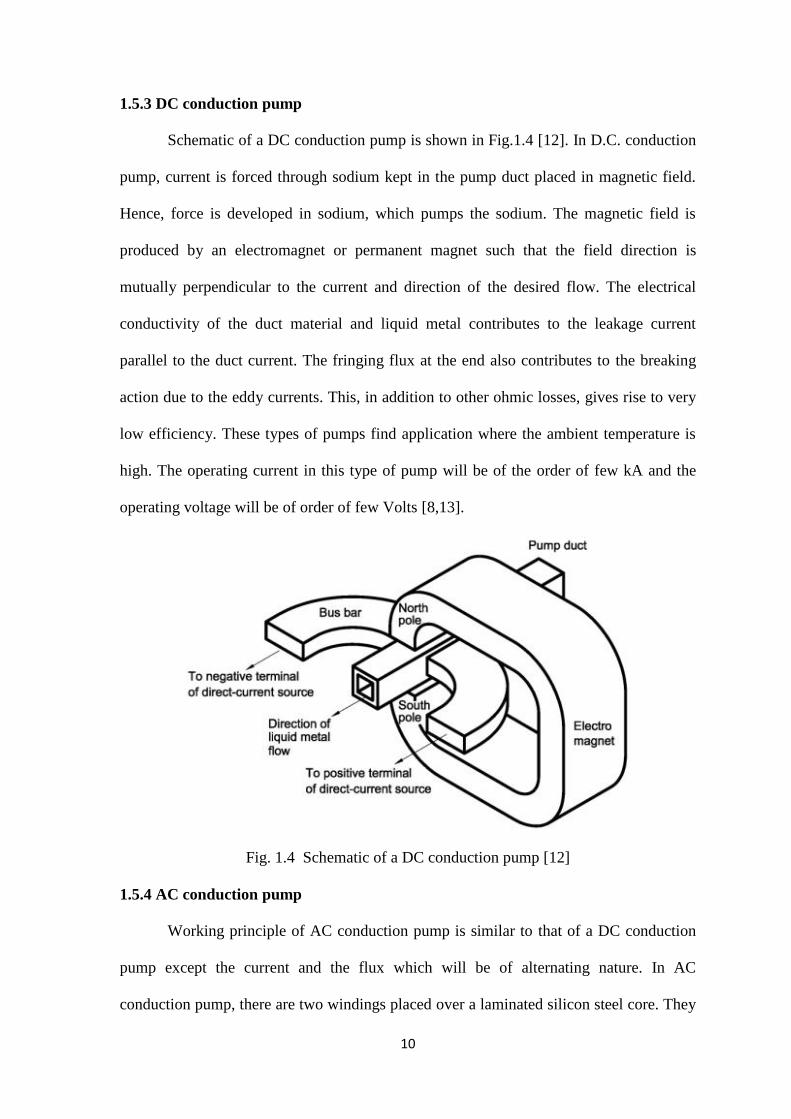
1.5.3 DC conduction pump
Schematic of a DC conduction pump is shown in Fig.1.4 [12]. In D.C. conduction
pump, current is forced through sodium kept in the pump duct placed in magnetic field.
Hence, force is developed in sodium, which pumps the sodium. The magnetic field is
produced by an electromagnet or permanent magnet such that the field direction is
mutually perpendicular to the current and direction of the desired flow. The electrical
conductivity of the duct material and liquid metal contributes to the leakage current
parallel to the duct current. The fringing flux at the end also contributes to the breaking
action due to the eddy currents. This, in addition to other ohmic losses, gives rise to very
low efficiency. These types of pumps find application where the ambient temperature is
high. The operating current in this type of pump will be of the order of few kA and the
operating voltage will be of order of few Volts [8,13].
Fig. 1.4 Schematic of a DC conduction pump [12]
1.5.4 AC conduction pump
Working principle of AC conduction pump is similar to that of a DC conduction
pump except the current and the flux which will be of alternating nature. In AC
conduction pump, there are two windings placed over a laminated silicon steel core. They

11
are primary multi-turn coil and secondary single-turn coil. Sodium is placed in the duct.
Secondary current alternating in nature is induced in single turn short circuited secondary
coil due to linking of primary main flux. The secondary alternating current also passes
through sodium placed in the duct since duct is part of secondary single turn coil. The
primary winding produces pulsating field in the same core. This field interacts with the
alternating current in sodium resulting in a unidirectional pumping force. The pressure
developed in the pump pulsates at twice the supply frequency as explained below.
Magnetic force acting on sodium is calculated as per Eqn. 1.1, where B and I are
alternating in nature as given below.
tsinBB max (1.2)
)(sinmax tII (1.3)
where ωt = 2πft and f is the supply frequency. Then the force Eq. 1.1 yields
LtItBF )(sinsin maxmax (1.4)
by using trigonometric identities, we can write
2
sinsincos)cos1(maxmax
ttIBF (1.5)
The termωt gives rise to double frequency pulsation in developed pressure which can
create noise and vibration. AC conduction pumps find applications in various
experimental liquid metal loops having low head and flow rate. Conduction pumps are
not normally used except in certain high temperature requirements due to their lower
efficiency in the order of 2 – 5 %.
1.5.5 Flat linear induction pump (FLIP)
Flat linear induction pump is the simplest form of linear induction pump. The
schematic of FLIP [12] is shown in Fig.1.5. The FLIP consists of duct carrying sodium
and a three phase stator winding placed in slots perpendicular to the direction of flow

12
which generates a traveling magnetic field. A copper bar is brazed at both sides of duct
along the length which plays the role of end ring like in conventional cylindrical
induction motor. When the stator is excited from a three phase power supply, it creates a
traveling magnetic field along the pump duct, inducing electric current in the conducting
liquid sodium. The interaction between the traveling magnetic field of stator and the
induced current in sodium produces an electromagnetic body force, pumping the liquid
sodium through the duct.
Fig. 1.5 Schematic of FLIP [12]
1.5.6 Annular linear induction pump (ALIP)
The general assembly of an Annular Linear Induction Pump (ALIP) [12] is shown
in Fig.1.6. In ALIP, the annular duct contains the liquid sodium. The stator consists of
three-phase circular distributed winding over the duct. The coils are placed in the slots of
laminated stator stacks. The working principle of ALIP is similar to that of FLIP. The
stator produces a radial magnetic field in annular duct region, travelling linearly along the
length of annulus and linking with sodium in annular gap, which induces current in the
sodium filled in annulus. Interaction of this induced current in sodium with the stator
magnetic field produces a pumping force in sodium. ALIP has potential to operate as

13
sodium submersible pump at higher temperatures. Hence, this type of pump is chosen for
development to meet the objective of research work [12].
Fig. 1.6 : General Assembly and Principle of an ALIP [12]
1.6 Status of EM Pumps - a review
Electromagnetic pumps of various types have been designed, manufactured and
tested in various countries. Many of these pumps were used in experimental facilities and
many in nuclear reactors. Electromagnetic pumps are mainly used for pumping sodium
metal. The literature on electromagnetic pump development is quite scattered since not
many details are available at one place in open literature. Therefore, it was considered to
list the available details of various electromagnetic pumps developed around the globe.
The survey of electromagnetic pumps is arranged country-wise. The pumps of various
countries cannot be compared in all respects since they were designed to meet specific
14
application of each country’s program, moreover these pumps were developed in different
periods of time also. Therefore, some of the relevant parameters of the pumps developed
in various countries are presented in this chapter.
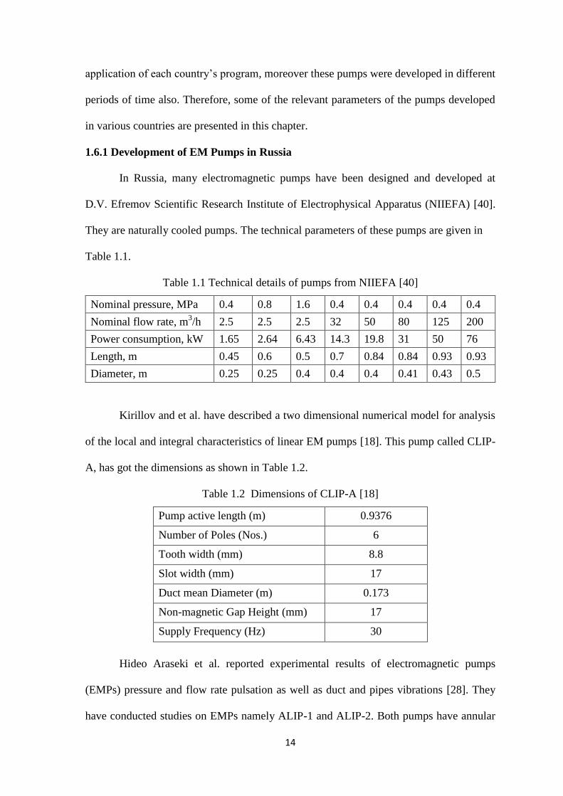
1.6.1 Development of EM Pumps in Russia
In Russia, many electromagnetic pumps have been designed and developed at
D.V. Efremov Scientific Research Institute of Electrophysical Apparatus (NIIEFA) [40].
They are naturally cooled pumps. The technical parameters of these pumps are given in
Table 1.1.
Table 1.1 Technical details of pumps from NIIEFA [40]
Nominal pressure, MPa 0.4 0.8 1.6 0.4 0.4 0.4 0.4 0.4
Nominal flow rate, m3/h 2.5 2.5 2.5 32 50 80 125 200
Power consumption, kW 1.65 2.64 6.43 14.3 19.8 31 50 76
Length, m 0.45 0.6 0.5 0.7 0.84 0.84 0.93 0.93
Diameter, m 0.25 0.25 0.4 0.4 0.4 0.41 0.43 0.5
Kirillov and et al. have described a two dimensional numerical model for analysis
of the local and integral characteristics of linear EM pumps [18]. This pump called CLIP-
A, has got the dimensions as shown in Table 1.2.
Table 1.2 Dimensions of CLIP-A [18]
Pump active length (m) 0.9376
Number of Poles (Nos.) 6
Tooth width (mm) 8.8
Slot width (mm) 17
Duct mean Diameter (m) 0.173
Non-magnetic Gap Height (mm) 17
Supply Frequency (Hz) 30
Hideo Araseki et al. reported experimental results of electromagnetic pumps
(EMPs) pressure and flow rate pulsation as well as duct and pipes vibrations [28]. They
have conducted studies on EMPs namely ALIP-1 and ALIP-2. Both pumps have annular

15
ducts of return flow type, i.e. sodium is pumped upward in an outer duct between inner
and outer magnetic structure and then is flowing downward over the central duct. The
details of the pumps are given in Table 1.3.
Table 1.3 Specification of ALIP-1 and ALIP-2 [28]
Nominal Parameters ALIP-1 ALIP-2
Flow Rate (m3/min) 2.1 7.2
Developed pressure (MPa) 0.2 0.15
Frequency (Hz) 20 50
Phase Voltage (V) 225 380
Phase Current (A) 60 180
Stator Length (m) 0.938 0.85
Duct Average Diameter (m) 0.173 0.296
Duct Width (m) 0.01 0.012
Number of winding poles 6 6
Number of winding slots 36 36
1.6.2 Development of EM Pumps in France
Two Annular Linear Induction Pumps have been described in the specifications of
French company Novatome [45]. The pumps have got the trade names IA 21 and IA 81
and its details are given in Table 1.4. Details of other pumps are given in Table 1.5.
Table 1.4 Details of IA 21 and IA 81 [45]
Nominal Parameters IA 21 IA 81
Flow Rate (m3/hr) 4 8
Na Temperature (οC) 600 600
Differential Pressure rise (bars) 1.3 1.5
Active Power (kW) 2 2.5
Current at nominal flow (A) 4.5 6
Preheating Secondary circuit voltage (V) 6.5 13

16
Table 1.5 Details of ALIP from Novatome [45]
Description IA 124 IA 251 IA 501 IA 1401
Delivery (m3/h) 12 25 50 140
Na Temperature (°C) 600 600 600 600
Differential pressure (bars) 3 5 5 4
N.P.S.H. (bars) 0.8 0.8 0.8 1
Active Power (kW) 8 25 45 80
Construction and tests in sodium of a 600 m3/h ALIP were carried out. The specifications
of the pump are in Table 1.6.
Table 1.6: Specification of 600 m3/h ALIP [41]
Overall length (mm) 3930
Overall transverse dimensions (mm) 740 x 790
Pump weight inclucive of frame (tons) 4.5
Connecting duct diameter (mm) 219
Cooling mode Axial air cooling
Air flow rate (m3/hr) 4990
Head loss in cooling (mbar) 34
Power supply Cyclo-converter 460 kVA
Frequency range 0-15 Hz
Calculated performance Pump with
no end pole
Pump with
end pole
Pump with
end pole
Sodium temperature (°C) 200 200 400
Nominal flow rate (m3/hr) 480 480 600
Differential pressure (bar) 4.42 5.17 5.45
Frequency (Hz) 8 8 10
Voltage per phase (V) 265 265 365
Current per phase (A) 295 295 295
Power requirement (kW) 143 144 193
Efficiency (%) 41.1 47.8 47
Power factor 0.611 0.615 0.597
Sodium velocity (m/s) 5.2 5.2 6.5

17
1.6.3 Development of EM Pumps in Japan
Nakazaki et al. [25] have described a sodium immersed self-cooled
electromagnetic pump. The pump diameter is about 0.5 m and length about 1 m. About
90 % of the total heat generated at the stator is calculated to be transferred to the sodium
inside the duct. The candidate materials proposed by Nakazaki et al. for sodium immersed
self-cooled electromagnetic pump are given in Table 1.7. Model pump design
specifications are provided in Table 1.8.
Table 1.7 Candidate materials for sodium immersed EM pump [25]
Electrical
Components
Operating
Temperature Required Functions Candidate Materials
Conductor 550°C High Electrical
Conductivity &
Mechanical Strength
Alumina-Dispersion
Strengthened Copper
Insulation 550°C High BOV
Characteristics, High
Resistivity, Mechanical
Strength
Alumina-Cloth Backed
Mica-Tape
Lamination 550°C Magnetic Characteristics. Ceramic-Coated
Electrical Steel
Table 1.8 Model pump design specifications [25]
Parameter Self-cooled ALIP specifications
Flow rate (m3/min) 1
Developed head (MPa) 0.37
Sodium temperature (°C) 350
NPSH (m Sodium) 10
Voltage (V) 350
Current (A) 85
Power factor 0.53
Input power (kVA) 51
Efficiency (%) 22
A 160 m3/min capacity sodium immersed self cooled electromagnetic pump has
also been developed for application as a main circulation pumps of FBR [26]. This

18
advanced pump is a submersible annular linear induction pump designed to be self-cooled
by immersing into sodium and applying high temperature electrical insulation. Almost all
the internal electrical losses were transferred to the surrounding sodium which can be
recovered as electricity by turbine generators. The boundary between flow stability and
instability of the EM pump operation has been defined by peak position of the Q-H curve,
which was specified by magnetic Reynolds’ number times slip of 1.4 to 1.5 at 335 °C.
The specifications of the pump are indicated in Table 1.9.
Table 1.9 Details of submersible 160 m3/min EM pump [26]
Parameter ALIP Specifications
Flow rate (m3/min) 160
Developed pressure (MPa) 0.25
Sodium temperature (°C) 335
Input power (kW) 1680
Terminal voltage (V) 1350
Phase current (A) 884
Frequency (Hz) 20
Number of poles 14
Flow gap (mm) 77
Flow velocity (m/s) 10.4
Number of coils 84 x 2
Outer dia. of casing (mm) 1900
Boundaries SUS 304, ALLOY 625
Stator iron Electrical Steel
Coil electrical insulations Alumina Cloth, glass
cloth and mica tape
Coil conductors Copper
1.6.4 Development of EM Pumps in USA
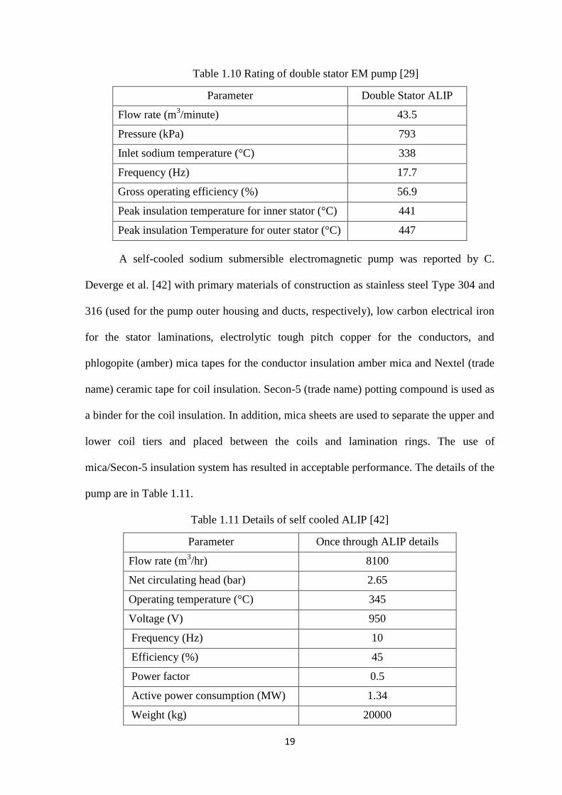
A double stator electromagnetic pump has been described in [29] for the primary system
of the Advanced Liquid Metal Reactor. The ratings of the pump are in Table 1.10.
19
Table 1.10 Rating of double stator EM pump [29]
Parameter Double Stator ALIP
Flow rate (m3/minute) 43.5
Pressure (kPa) 793
Inlet sodium temperature (°C) 338
Frequency (Hz) 17.7
Gross operating efficiency (%) 56.9
Peak insulation temperature for inner stator (°C) 441
Peak insulation Temperature for outer stator (°C) 447
A self-cooled sodium submersible electromagnetic pump was reported by C.
Deverge et al. [42] with primary materials of construction as stainless steel Type 304 and
316 (used for the pump outer housing and ducts, respectively), low carbon electrical iron
for the stator laminations, electrolytic tough pitch copper for the conductors, and
phlogopite (amber) mica tapes for the conductor insulation amber mica and Nextel (trade
name) ceramic tape for coil insulation. Secon-5 (trade name) potting compound is used as
a binder for the coil insulation. In addition, mica sheets are used to separate the upper and
lower coil tiers and placed between the coils and lamination rings. The use of
mica/Secon-5 insulation system has resulted in acceptable performance. The details of the
pump are in Table 1.11.
Table 1.11 Details of self cooled ALIP [42]
Parameter Once through ALIP details
Flow rate (m3/hr) 8100
Net circulating head (bar) 2.65
Operating temperature (°C) 345
Voltage (V) 950
Frequency (Hz) 10
Efficiency (%) 45
Power factor 0.5
Active power consumption (MW) 1.34
Weight (kg) 20000

20
Testing of a 43.5 m3/min EM pump in sodium has been described in [27]. The
testing was carried at various v/f ratios. Details of the EM pump are given in Table 1.12.
Table 1.12 Details of 43.5 m3/min electromagnetic pump [27]
Flow (m3/min) 43.5
Pressure (kPa) 98
Sodium temperature (°C) 352
Net positive suction head (m-Na) 13.3
Input (kVA) 317
Terminal voltage (V) 850
Frequency (Hz) 18.7
Flow velocity (m/s) 9.2
GEC-REL direct current conduction pumps are designed for sodium and NaK
liquid metals at operating temperatures up to 650°C. Four standard sizes cover a range of
outputs, the maximum nominal output of 20 m3/h with a developed head of 6.7 kg/cm
2.
With low voltage electric supply, the conductors need no insulation and therefore these
pumps are suitable for application at high temperatures without the need for cooling,
provided that the magnet temperature does not rise above 550°C. The D.C. pump has a
characteristic of non-pulsating flow and can operate free from cavitation at an inlet
pressure as low as 0.3 kg/cm2 absolute.
The magnetic field of the pump is produced by a stabilized permanent magnet
manufactured from Alcomax III. The duct is made of stainless steel 316. Two oxygen free
copper electrodes are nickel plated to prevent their corrosion. They are brazed to the duct
using high temperature vacuum technique.
Three annular linear induction pumps namely MK-1, MK-II and Auxiliary EM
Lithium pump were developed by Liquid Metal Engineering. The MK-1 pump was
operated flawlessly for 8600 h. Maximum temperature rise in the pump was about 55 °C,
during pumping of lithium at 270 °C. Efficiency at the design point was 48 %.

21
Changes in MK-II include higher flow and heat capability (750 gpm, 62 psi) and
re-design of inlet region to achieve improved hydraulic characteristics were incorporated.
Improved hydraulic design of MK-II included magnetically graded end poles to reduce
the end losses. A streamlined flux-return torpedo resulted in less hydraulic pressure drop
through the pump. Due to the above changes, the pump was able to operate at lower
NPSH with lithium as a pumping fluid. Details of EM pump for lithium pumping are
given in Table 1.13.
Table 1.13 Details of EM pump for Lithium pumping
Parameter MK-I MK-II Auxiliary pump
Structural design
basis
Requirements of ASME Code Section III, Class 1; except
no “N” stamp required.
Fluid Lithium
Line voltage (V AC) 480 660 200
Line current (A) 90 200 40
Input power (kW) 60 200 20
Phases 3 3 3
No. of poles 6 6 6
Design point 0.038 m3/s at
228 kPa
0.047 m3/s at
428 kPa
0.00063 m3/s at
276 kPa
Duct diameter (cm) 15.2 15.2 5.08
Length (cm) 101 213 91.44
Diameter (cm) 40.6 40.6 25.4
Weight (kg) 522.7 613.63 75.91
Maximum
Temperature (°C)
538 648 538
Cooling Natural convection in air, radiation and heat transfer to
lithium
External
environment
Air at ambient conditions
1.6.5 Development of EM Pumps in England
Electromagnetic pumps were designed and manufactured in England mainly for DFR and
PFR. FLIP, ALIP, DC Conduction pumps have been described in [13,20]

22
Details of one EM pump manufactured in England are given in Table 1.14 [13].
Table 1.14 Specification of the electromagnetic pump manufactured in England [13]
Fluid Sodium
Pump output (hp) 14
Maximum metal temperature (°C) 500
Capacity (gpm) 400
Generated pressure head (lb/in2) 50
Frequency (Hz) 50
Power factor 0.3
Efficiency in % 36
1.6.6 Development of EM Pumps in Germany
The manual of Interatom describes two electromagnetic pumps of capacities 50
m3/h and 100 m
3/h [43]. The pumps described are reflux types. At the end of the pump
length, the liquid metal flow is deflected and flows through the inner pipe to the outlet.
The magnetic frame can be removed or mounted at the free end without interfering in the
closed pipe system. Due to the eddy current losses in the annular gap, the pump can be
started up without external trace heating. The technical data are given in Table 1.15.
Table 1.15: Technical data of 50 m3/h and 100 m
3/h EM pump [43]
Design (m3/h) 100 50
Operating temperature (°C) 200 550 200 550
Discharge capacity (m3/h) 100 50
Discharge pressure (bar) 6.4 9.7 3.2 4.6
Power consumption in (kVA) 108 160 54 80
Operating voltage (V) 256 380 255 380
Power factor 0.77 0.85 0.76 0.83
Efficiency (%) 15.3 17 13.8 15.3
Weight (kg) 280 180
Number of coils 36 18
23
Comparison regarding MHD instability has been made in [21] among i) Soviet
CLIP-3 / 3500 with a maximum sodium delivery of 3600 m3/h, ii) a French Prototype
with a maximum delivery of 700 m3/h and iii) a West German EMP of 600 m
3/h built by
Interatom Society. Parameters of all the three electromagnetic pumps are provided in
Table 1.16.
Table 1.16 Comparison of parameters of various EM pumps [21]
Parameters Prototype
French
CLIP-3/ 3500
Russian
Interatom NWA
German
Temperature (°C) 200 300 350
Delivery (m3/h) 600 3600 609
Frequency (Hz) 10 50 40
Velocity (m/s) 6.5 12.9 9.52
Pole pitch (mm) 450 156 210
Wave number k (m-1
) 6.98 20.14 14.96
Rm 3.33 0.96 3.09
Duct height (mm) 32.4 26 14.9
Mean radius (mm) 125.8 475 190
Length of the inductor (mm) 2270 5000 1000
It is seen that Russian pump is having capacity much higer than other two pumps hence
length and diameter are high. All the three pumps operate at different frequency. Design
velocity in the Russian pump is 12.9 m/s which is higher than the conventional design
value of 10.0 m/s [12]
1.6.7 Development of EM Pumps in India
In India, developmental work related to EM Pump started with the development of
Flat Linear Induction Pump (FLIP) of 20 m3/h, 5 kg/cm
2 capacity at Indira Gandhi Centre
for Atomic Research, Kalpakkam. The pump was manufactured, tested and is being used
in an experimental sodium loop. Further development of FLIP was not pursued because
of stringent requirement of stainless steel duct to copper welding required in it, hence
24
attention switched over to annular linear induction pump (ALIP) which does not need
stainless steel to copper welding and manufacturing is comparatively easy. ALIPs of
5 m3/h, 5 kg/cm
2 capacity and 170 m
3/h, 4 kg/cm
2 capacity were developed and tested.
Further, DC Conduction Pump of 0.36 m3/h, 1.45 kg/cm
2 capacity was developed and
tested. The pumps developed proved indigenous design and manufacturing capability for
sodium application. These ALIPs and FLIPs were designed and manufactured using
conventional electrical insulation in the pump winding. The developed pumps were used
in auxiliary circuits of Prototype Fast Breeder Reactor. The developed DC conduction
pump can operate in sodium submerged condition. Specifications of FLIP, ALIP and DC
Conduction Pump developed are given in Table 1.17, Table 1.18 and Table 1.19
respectively [8, 19].
Table 1.17 Specification of Indian FLIP
Flow (m3/h) 20
Pipe size (mm) 63
Differential pressure (kg/cm2) 5
Fluid Sodium
Temperature (οC) 530
Rating (kVA) 36
Efficiency (%) 20
Insulation Class H
Table 1.18 Specification of Indian ALIP [19]
Flow (m3/h) 5 170
Head (kg/cm2) 5 5
3 Phase line voltage (V) 415 360
Sodium temperature (οC) 400 450
Input power (kW) 11.5 98
Power factor 0.47 0.5
Efficiency (%) 6.8 19
Phase current (A) 21 308
Winding Insulation Class H Class H
25
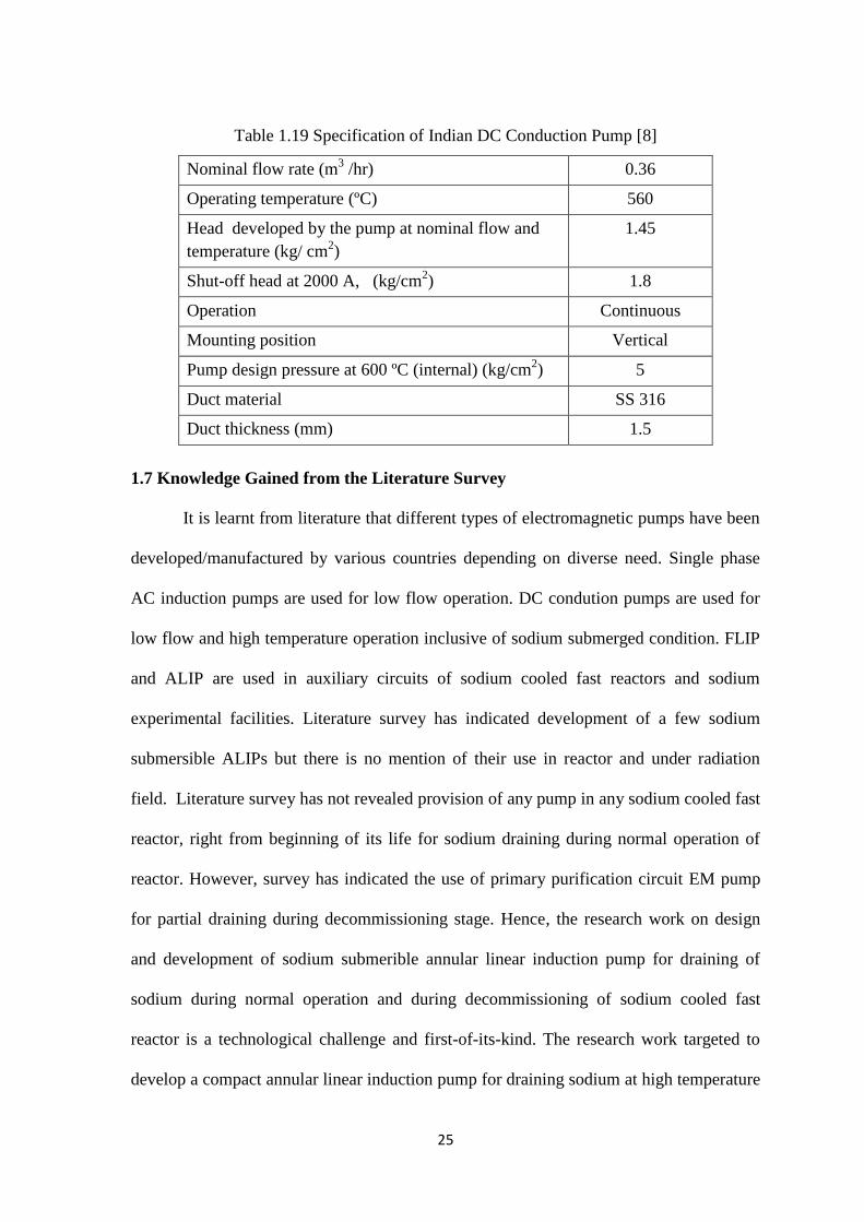
Table 1.19 Specification of Indian DC Conduction Pump [8]
Nominal flow rate (m3 /hr) 0.36
Operating temperature (ºC) 560
Head developed by the pump at nominal flow and
temperature (kg/ cm2)
1.45
Shut-off head at 2000 A, (kg/cm2) 1.8
Operation Continuous
Mounting position Vertical
Pump design pressure at 600 ºC (internal) (kg/cm2) 5
Duct material SS 316
Duct thickness (mm) 1.5
1.7 Knowledge Gained from the Literature Survey
It is learnt from literature that different types of electromagnetic pumps have been
developed/manufactured by various countries depending on diverse need. Single phase
AC induction pumps are used for low flow operation. DC condution pumps are used for
low flow and high temperature operation inclusive of sodium submerged condition. FLIP
and ALIP are used in auxiliary circuits of sodium cooled fast reactors and sodium
experimental facilities. Literature survey has indicated development of a few sodium
submersible ALIPs but there is no mention of their use in reactor and under radiation
field. Literature survey has not revealed provision of any pump in any sodium cooled fast
reactor, right from beginning of its life for sodium draining during normal operation of
reactor. However, survey has indicated the use of primary purification circuit EM pump
for partial draining during decommissioning stage. Hence, the research work on design
and development of sodium submerible annular linear induction pump for draining of
sodium during normal operation and during decommissioning of sodium cooled fast
reactor is a technological challenge and first-of-its-kind. The research work targeted to
develop a compact annular linear induction pump for draining sodium at high temperature

26
without external cooling and to operate at intense radiation field in the reactor, to over
come the technological challenge.
1.8 Organization of Thesis
The aim of the present research is to design and develop a compact high
temperature sodium submersible annular linear induction pump which can be used for
draining of primary sodium from main vessel of PFBR.
Chapter 2 deals with development of a mathematical model for annular linear
induction pump. In this chapter, various equations of of the pump parameters are derived
using basic principles.
Chapter 3 comprises of design of submersible annular linear induction pump and
analysis.
Chapter 4 gives a detailed account of annular linear induction pump development
and manufacture. Various aspects of the pump development are dealt here.
Chapter 5 illustrates the experimental sodium facility used for testing the
developed submersible ALIP. This chapter also deals with experimental performance
evaluation of the submersible ALIP developed.
Chapter 6 briefs about summary and future prospects.

27
CHAPTER – 2
DEVELOPMENT OF MATHEMATICAL MODEL FOR ANNULAR
LINEAR INDUCTION PUMP (ALIP)
2.1 Introduction
The aim of research work is to develop sodium submersible device which can
pump out radioactive sodium at 200 °C from main vessel of PFBR [2]. Literature survey
and study of various systems lead to the conclusion that annular linear induction pump
(ALIP) has the potential to achieve the research aim. Use of mineral insulated winding
can overcome the challenges associated in the development of ALIP for operation at high
temperature and radiation field. Literature survey also indicated that use of mineral
insulated cable in ALIP is first of its kind and is not reported in open literature.
Parametric studies on conventional ALIP [9, 10, 11, 15, and 19] was carried out for
understanding the functionality of ALIP and development of mathematical model was
carried out.
This chapter deals with derivation of governing equations used in design of ALIP.
2.2 Design Methodology of Annular Linear Induction Pump (ALIP)
Generally, design and performance evaluation of ALIP are being done using
equivalent circuit analysis similar to analysis being carried out for an induction motor [16,
17]. The equivalent circuit approach is based on lumped model of ALIP and is used for
determining various parameters [12].
2.3 Working Principle and Equivalent Circuit of ALIP
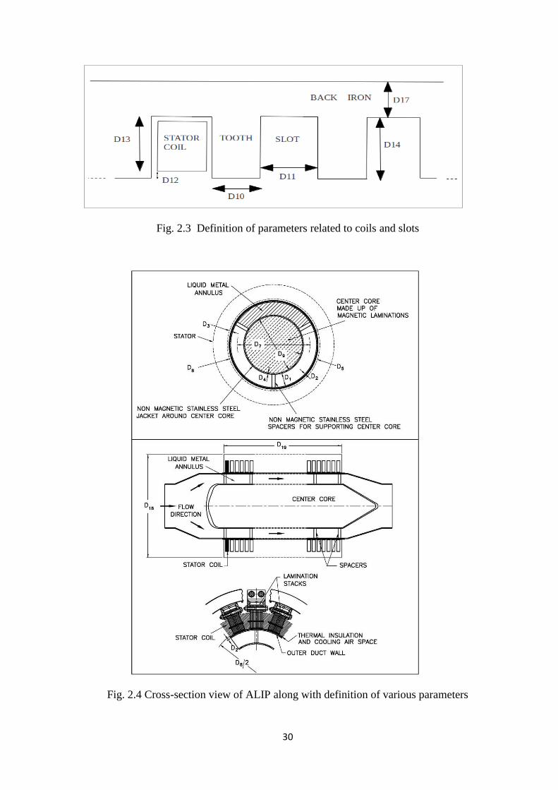
Schematic construction of ALIP is shown in Fig. 2.1. It consists of annular
stainless steel duct over which three phase winding is placed. Laminated stator core and
centre core provide high permeance path for magnetic flux. The sodium to be pumped is
placed in a stainless steel annular duct. ALIP has a 3-phase distributed winding which

28
produces a linearly traveling magnetic field. This traveling magnetic field induces current
in sodium. Interaction of the induced current in sodium with the traveling magnetic field
gives rise to a pumping force as per equation 1.1.
Fig. 2.1: Schematic construction and working principle of ALIP [12]
2.3.1 Equivalent circuit of ALIP
The equivalent circuit of ALIP, similar to equivalent circuit of an induction motor
is depicted in Fig. 2.2. The symbol Eb in the equivalent circuit (Fig. 2.2) represents
applied phase voltage. The constructional details of ALIP along with definition of various
parameters are shown in Fig. 2.3 and Fig. 2.4 [12, 20]. The coil in ALIP is a circular pan-
cake type which surrounds the central core and sodium completely. The coils are placed
in slots and are thermally and electrically insulated from the stainless steel duct. The
conductor in the coil does not occupy full space due to insulation. The entire flux
produced by primary winding does not link the secondary and hence, the primary winding

29
has got a leakage reactance. The magnetic circuit is completed by cold rolled grain
oriented (CRGO) laminations which are stacked together and arranged along the
periphery of the duct as shown in Fig. 2.4. The non-magnetic stainless steel duct forms
the annular space through which liquid sodium flows. This duct also has circulating
current and it acts as short circuited secondary. The sodium in the duct is equivalent to a
single turn secondary.
In the equivalent circuit, all the parameters of the secondary are referred to the
primary side. Leakage inductance of secondary is assumed to be negligible. The symbols
used in figures and derivations are given in Table- 2.1. The equivalent circuit analysis is
carried out per phase basis with the assumption of symmetrical phase distribution of
voltage and current in all the three phases. The end-effects are neglected in this approach.
The cross-section view of ALIP is shown in Fig. 2.4.
Fig. 2.2: Equivalent circuit of ALIP
30
Fig. 2.3 Definition of parameters related to coils and slots
Fig. 2.4 Cross-section view of ALIP along with definition of various parameters
31
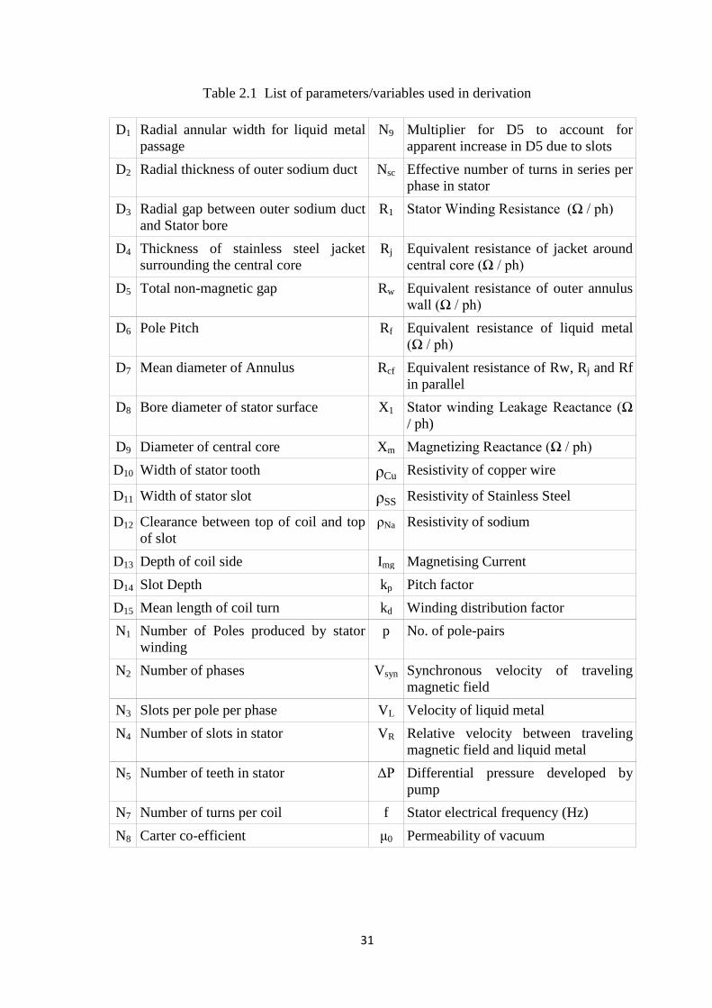
Table 2.1 List of parameters/variables used in derivation
D1 Radial annular width for liquid metal
passage
N9 Multiplier for D5 to account for
apparent increase in D5 due to slots
D2 Radial thickness of outer sodium duct Nsc Effective number of turns in series per
phase in stator
D3 Radial gap between outer sodium duct
and Stator bore
R1 Stator Winding Resistance (Ω / ph)
D4 Thickness of stainless steel jacket
surrounding the central core
Rj Equivalent resistance of jacket around
central core (Ω / ph)
D5 Total non-magnetic gap Rw Equivalent resistance of outer annulus
wall (Ω / ph)
D6 Pole Pitch Rf Equivalent resistance of liquid metal
(Ω / ph)
D7 Mean diameter of Annulus Rcf Equivalent resistance of Rw, Rj and Rf
in parallel
D8 Bore diameter of stator surface X1 Stator winding Leakage Reactance (Ω
/ ph)
D9 Diameter of central core Xm Magnetizing Reactance (Ω / ph)
D10 Width of stator tooth ρCu Resistivity of copper wire
D11 Width of stator slot ρSS Resistivity of Stainless Steel
D12 Clearance between top of coil and top
of slot
ρNa Resistivity of sodium
D13 Depth of coil side Img Magnetising Current
D14 Slot Depth kp Pitch factor
D15 Mean length of coil turn kd Winding distribution factor
N1 Number of Poles produced by stator
winding
p No. of pole-pairs
N2 Number of phases Vsyn Synchronous velocity of traveling
magnetic field
N3 Slots per pole per phase VL Velocity of liquid metal
N4 Number of slots in stator VR Relative velocity between traveling
magnetic field and liquid metal
N5 Number of teeth in stator ΔP Differential pressure developed by
pump
N7 Number of turns per coil f Stator electrical frequency (Hz)
N8 Carter co-efficient μ0 Permeability of vacuum

32
2.4 Estimation of Equivalent Circuit Parameters – A First Principle Approach
Design and performance evaluation of ALIP is done using the equivalent circuit
approach, from the first principles.
2.4.1 Stator winding resistance (R1)
Conventional ALIP has circular pan-cake winding which is made of enameled
insulated copper wire. This circular winding is housed in stator slot. The expression for
conventional ALIP winding resistance is obtained from the formula
Area(A)
)(Length)(y resistivit=)(R Resistance 1
L (2.1)
Total length of one phase of primary winding 2
4715
N
NND= (2.2)
Assuming 60% of slot cross-sectional area is occupied by copper
Copper area in one slot = 7
1114 0.6
N
DD= (2.3)
As a standard practice in design, 1114 5D=D
Wire cross-section (A) 7
2
11
7
1111 30.65
N
D=
N
DD= (2.4)
2
112
4
2
715
7
2
11
2
4715
133 DN
NNDρ=
N
D
N
NNDρ
=A
ρl=R Cu
Cu
(2.5)
The assumption of 60% of slot cross-section area occupied by copper and equality
1114 5D=D are made to have similarity of expression for R1 given in Handbook of
Electromagnetic Pump Technology [12]. However this expression is not used in the
design calculation for the developed ALIP. R1 is calculated using Eq 2.1 and actual cross-
section of copper in MI cable without considering the slot fill factor of 60%. The
calculation carried out is indicated in Annexure-A Eqn. (A-22) in Page no. 120.

33
2.4.2 Stator winding leakage reactance
The leakage reactance (X1) is due to the fact that some of the primary flux is
leaked from main flux path resulting in leakage reactance of the winding. The total
leakage flux mainly consists of two components ( 1 and 2 ) as shown in Fig. 2.5 where
1 is the leakage flux passing through winding portion and 2 is the leakage flux where
winding is not present.
Fig. 2.5 Different leakage fluxes of primary winding
Let L be the inductance per coil and I current in the winding, then
Primary winding leakage reactance per phase becomes
31 2 NπfLN=X 1 (2.6)
212
71
77 L+L=I
N+I
N=I
N=L (2.7)
where, I is the current in the conductor of the winding & is the total leakage flux.
I
N=L 171 and
IN=L 2
72 (2.8)
Amp-turns at strip (refer Fig. 2.5) d 1 = x..13
7
D
NI (2.9)
Reluctance of the strip = FlowFlux of Area flowflux of Area
FlowFlux ofLength
0
11
0 μ
D=
μ (2.10)
Area for flux flow dxD8 , (flux flow referred in Eq 2.10 is parallel to pump
longitudinal axis)

34
This is because, the perimeter of stator lamination at the stator bore diameter through
which the flux passes (magnetic material width) is πD8, where D8 is the diameter of the
stator bore surface and height of the strip is dx.
11
80
13
71 x...
strip of reluctance
stripat mmf
D
dxπDμ
D
NI==d (2.11)
Turns enclosed by x.13
71
D
N=d (2.12)
dxD
Dx
D
NIx
D
N=dturns
11
80
13
7
13
71 .....
dxDD
xIμπDN=dturns
11
2
13
2
08
2
71
. (2.13)
of linkageflux 1117 dturns=N
dxDD
xIμπDNdturns
11
2
13
2
08
2
71
. (2.14)
13
0
3
11
2
13
8
2
72
11
2
13
8
2
7
11
2
13
2
08
2
71171
3
..D
00 x
DD
DNπμ=dxx
DD
DNπμ=dx
IDD
xIμπDN=
I
dturns=
I
N=L
…(2.15)
11
138
2
71
3D
DDNπμ=L 0 (2.16)
For flux 2 which is enclosed by the entire ampere turns of the slot.
IN= 7 turns-Amp
1280
11
20
11
20
2
flow flux of Area flow flux of Area
flow flux ofLength Reluctance
DD
D
μ
D=
μ= (2.17)
Area for flux 2 flow = πD8D12 where D8 is the diameter of the stator bore
surface and D12 is height as shown in Fig. 2.5.
11
128072
reluctance D
DπDμIN=
mmf= (2.18)

35
11
1280
2
7
11
12807727 .
D
DDN
D
DπDμ
I
INN=
I
N (2.19)
Total inductance
128138
11
2
721
27
17
3DD+
DD
D
πμN=L+L=
IN+
IN=L 0 (2.20)
Total Leakage Impedance of stator
128138
11
2
73131
322 DD+
DD
D
πμNNπfN=NπfLN=X 0
1
128138
11
2
731
5
13
102.48DD+
DD
D
NNNf=X (2.21 a)
Multiplying and dividing the Eq (2.21 a) by 2, above expression for X1 becomes
26
104.96 128138
11
2
731
5
1
DD+
DD
D
NNNf=X (2.21 b)
It can be observed that expression of X1 indicated in Eq (2.21 b) is same as of expression
of X1 given in Handbook of Electromagnetic Pump [12], this confirms the correctness of
methodology followed for estimation of expression for X1 from first principle approach.
2.4.3 Magnetizing reactance (Xm)
Magnetizing reactance (Xm) is responsible for producing flux in air gap.
Let flux per pole be Φ then Average air-gap flux density A= /
Peak value of flux density /A)/2)((=Bm (assuming a sinusoidal flux distribution)
Effective air gap length 59 DN=
where N9 is the multiplier to account for apparent increase in air-gap D5 due to the
presence of slots
59
0
59
0
59
1
2 turns-Amp DN
μA
π=DN
μ
B=DNH= m
m (2.22)
Fundamental component of stator mmf (Fa)
36
poleper turn amp1.35
p
KkIT=F
emph
a [17] (2.23)
Where, Fa – amplitude of fundamental component
I – Magnetising current (rms) = Img
Tph – Turns per phase = Nsc
km – distribution factor = kd
ke = span factor = kp
p – pole pairs = N1/2
In terms of the notations used in this thesis
11
21.35
2
1.35
N
KkNI=
N
KkNI=F
pdscmgpdscmg
a (2.24)
Equating equations (2.22) & (2.24)
59
01
1
2
21.35DN
μA
φπ=
N
KkNI pdscmg
dpsc
g
dpsc
gmgkkN
BDNN
μ
π=
kkN
NDN
μB
π=I
519
0
159
0 2
1
1.35
11
221.35
1
2
dpsc
g
dpsc
g
mgkkN
BDNN=
kkN
BDNN
π
π=I
51965197
100.4632
1
1.35
1
4
10
2 (2.25)
EA – voltage induced across Xm
1
2f22
1
N
Nφkk
π=E sc
TpdA (2.26)
167 NDπDB=φ gT (2.27)
pdscggsc
pdA kkNDπDπfB=NDπDBN
Nk=E 67167
1
2.22fk 2.22 (2.28)
591
76
2
6
5916
67 )(1015.06
100.463
2.22
DNN
DDkkNf=
KKN
BDNN
kkNDπDπfB=
I
E=X
pdsc
dpsc
g
pdscg
m
Am (2.29)
37
Multiplying and dividing by N2 i.e. Number of phases which are normally 3
591
76
2
26
591
76
2
2
2
6 )(
3
1015.06)(1015.06
DNN
DDkkNfN=
DNN
DDkkNfN
N=X
pdscpdsc
m
In the above expression, one N2 has been taken as 3 to have similarity with the expression
given in Handbook of Electromagnetic Pump[12].
591
76
2
26)(
105.02DNN
DDkkNfN=X
pdsc
m (2.30)
The above expression (2.30) is valid for a 3 phase machine only.
2.4.4 Equivalent resistance of outer annulus wall (Rw):
Mean diameter of outer pipe = 21721
7 22
22
D+D+D=D
+D
+D (2.31)
The circumference length of outer pipe = )D+D+(Dπ 217 (2.32)
Pipe cross-section area (pump length x wall thickness) = )DN+D(ND 1051142 (2.33)
Cross-section Area /phase = 2
1051142
N
)DN+D(ND (2.34)
)DN+D(ND
)kk(N)ND+D+π(Dρ=
N
N
A
ρl=R
dpscSS
ondary
primary
w
1051142
2
2217
2
sec
(2.35)
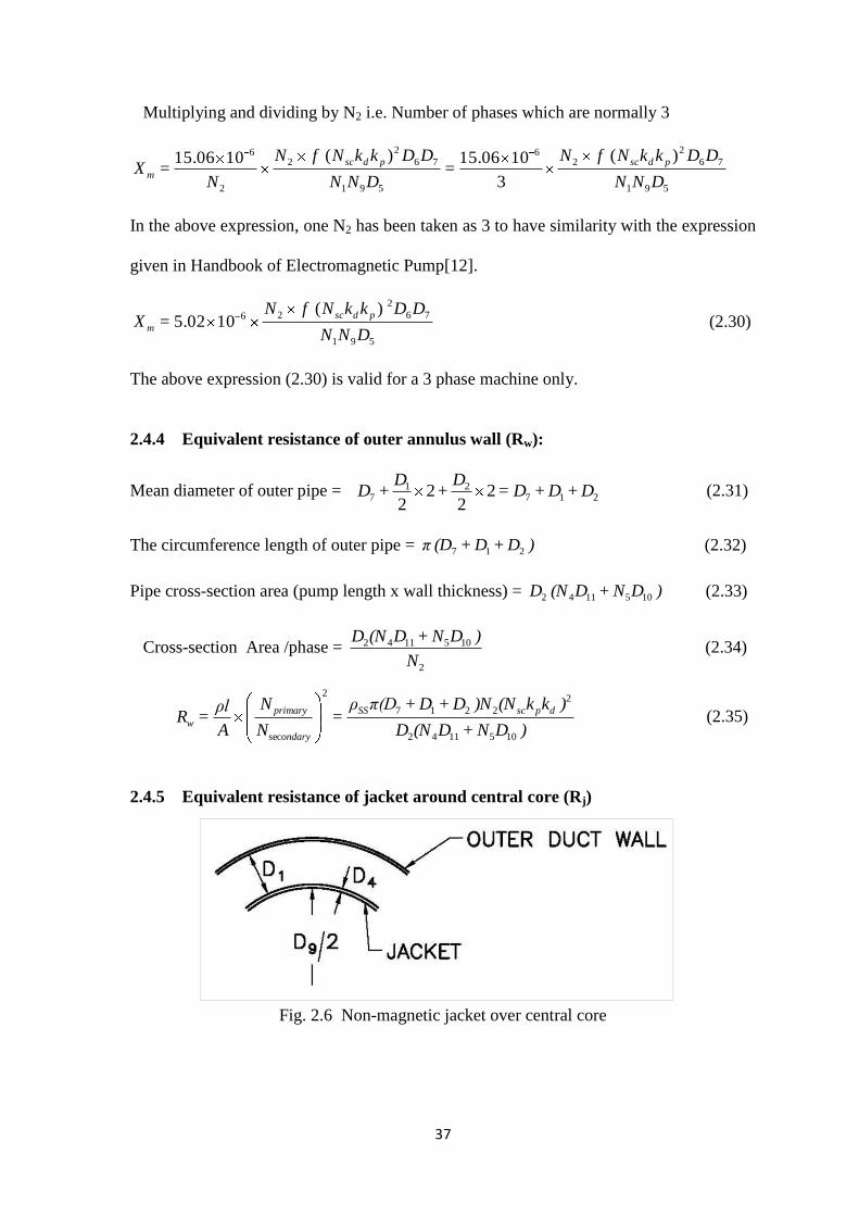
2.4.5 Equivalent resistance of jacket around central core (Rj)
Fig. 2.6 Non-magnetic jacket over central core

38
As per Fig. 2.6,
Mean circumferential length of jacket = )D+π(D=D
+Dπ 494
9 22
(2.36)
Jacket cross-section area = pump length x wall thickness = 2
1051144
N
)DN+D(ND (2.37)
)DN+D(ND
)kk(N)ND+π(Dρ=
N
N
A
ρl=R
dpscSS
ondary
primary
j
1051144
2
249
2
sec
(2.38)
2.4.6 Equivalent resistance of liquid metal (Rf):
Mean circumferential length of liquid metal = 7D
Cross-section of liquid metal per phase = 2
1051141
N
)DN+D(ND (2.39)
)DN+D(ND
)kk(NNDπρ=R
dpscNa
f
1051141
2
27 (2.40)
Mean length of annular space = 7Dπ
Stator length = τ x N1 where τ is pole pitch, so Rf can also be expressed as
11
2
27
NτD
)kk(NNDπρ=R
dpscNa
f (2.41)
2.4.7 Derivation of differential pressure developed on liquid sodium by ALIP
The differential pressure developed on liquid sodium by ALIP was derived using
schematic shown in Fig 2.7.
Fig. 2.7: Schematic of annular gap D1

39
D1 is annular gap where liquid sodium is filled
At a point x, gap flux density = Bx
x)βt(ωB=B mx sin (2.42)
where, τ
π=
τ
π=β
2
2
Synchronous velocity = 2 f τ = Vsyn
slip syn
Lsyn
V
VV=s (2.43)
and relative velocity
VR = Vsyn – VL = s Vsyn
At point x emf induced = Bx L VR ( in this section L is the length)
Current in the element dx = 7
1
1
7 Dπρ
dxDLVB=
dxD
Dπρ
LVB=I
Na
Rx
Na
Rxx (2.44)
Force on the element dx = dxDπρ
DVLB=LIB=dF
Na
Rxxx
7
1
22
(2.45)
Force over a pole pair = dxBDπρ
DVL=F x
Na
Rp
2
7
1
2
(2.46)
dxx)βt(ω
B=x)dxβt(ωB=dxB mmx2
cos21sin 2222 (2.47)
= )cos2(2
2
x)dx)βt(ωdxBm applying limit 0 to 2 τ
=β
tω
β
τ)βt(ω+τ
B=
β
x)βt(ωx
B m
τ
m
2
sin2
2
2sin22
22
sin2
2
22
0
2
= β
tω
β
t)(ω+τ
B=
β
tω
β
π)t(ω+τ
B mm
2
sin2
2
sin22
22
sin2
2
2sin22
2
22
= 2
mB
40
Therefore, τBDπρ
DVL=dxB
Dπρ
DVL=F m
Na
Rx
Na
Rp
2
7
1
22
7
1
2
(2.48)
Total force on (N1/2) pole pairs = 22
1
2
7
1
2
1 NτB
Dπρ
DVL=
NF=F m
Na
Rp (2.49)
Differential pressure = 17
1
2
7
1
2
17 2 DDπ
NτB
Dπρ
DVL=
DDπ
F=
area
F=Δp m
Na
R (2.50)
L=πD7 and VR = s Vsyn substituting these values in the above equation
17
1
2
7
1
2
7
2
2 DDπ
NτB
Dπρ
DsVDπ=F m
Na
syn (2.51)
Re-arranging the equation
17
2
7
22
7
11
2 DDπ
sVDπB
Dρπ
NτD=F
synm
Na
(2.52)
Equivalent resistance of liquid metal Rf is given by
11
2
27
NτD
)kk(NNDπρ=R
dpscNa
f
Re-arranging the terms we get the following equation
f
dpsc
Na R
)kk(NN=
Dρπ
NτD2
2
7
11 (2.53)
The rms voltage induced in fluid per phase at synchronous velocity
syn
ma VDπ
B=e 7
2 (2.54)
Equivalent voltage referred to primary winding (i.e. voltage across Xm)
)kk(NVDπB
=)kk(Ne=E dpscsynm
dpscaA 72
(2.55)
2
222
7
22
2)kk(NVDπB
=Edpscsynm
A (2.56)
Re-arranging the above equation the following equation is obtained
41
2
22
7
22 2
)kk(NV
E=VDπB
dpscsyn
Asynm (2.57)
Substituting values derived in eqn (2.53) and (2.57) in (2.50) the following equation is
obtained
17
2
22
2
2
2
DπD
s
)kk(NV
E
R
)kk(NN=Δp
dpscsyn
A
f
dpsc
17
2
22
2
2
2
DπD
s
)kk(NV
E
R
)kk(NN=Δp
dpscsyn
A
f
dpsc (2.58)
synf
A
synf
A
QR
EsN=
VDDπR
sEN=Δp
2
2
17
2
2 (2.59)
The above expression (Eqn. 2.59) for differential pressure does not take into
account the hydraulic losses and entry and exit end-effect losses. The entry and exit losses
decrease with increase in number of poles and this effect has been accounted empirically
by the factor (N1-1)/(N1+1) [12]. After taking into account the exit and entry end-effect
losses, expression for pressure developed in ALIP is derived as;
synf
A
QR
EsN
+N
N=ΔP
2
2
1
1
1
1 (2.60)
2.5 Summary
Mathematical model for annular linear induction pump using first principle
approach was made. Derivation of formulae for equivalent circuit parameters like
winding resistance, leakage reactance, magnetizing reactance, resistance of wall, jacket,
pumped fluid and pressure developed by the pump were used in design. Derivation of the
formulae gives more in-sight of design of the pump and also it makes base for
modification in equivalent circuit for incorporating effect of eddy current loss in stainless
steel sheath of winding in newly designed pump.


42
CHAPTER – 3
SUBMERSIBLE ANNULAR LINEAR INDUCTION PUMP DESIGN AND ANALYSIS
3.1 Design Requirement
Using equivalent circuit approach, design and development of sodium submersible
annular linear induction pump for draining of sodium from PFBR Main Vessel is taken up.
This necessitated the development of annular linear induction pump which is totally enclosed in
stainless steel enclosure and its winding made of mineral insulated stainless steel sheathed
cable capable of withstanding temperature upto 550 °C. The design is aimed for compact,
hermetically sealed annular linear induction pump to achieve sodium submersible operation at
sodium temperature of 200 °C. An ALIP of 2.0 m3/h flow and 4.0 kg/cm
2 pressure head is
designed for sodium draining. While designing, care was taken to achieve pump diameter less
than 450 mm to facilitate easy insertion through available inspection canal in PFBR roof slab.
3.2 Design of Submersible Annular Linear Induction Pump
The flow rate of 2.0 m3/h was selected for the pump to maintain compactness of pump
having reasonable drain time. Pressure head of 4.0 kg/cm2 was selected to overcome static head
in PFBR vessel and frictional losses in the drain pipe. Design of ALIP was carried out as per
flow chart shown in Fig. 3.1 and the design calculations are provided in Appendix-A. ALIP is
designed with winding made from mineral insulated stainless steel sheathed cable which can
withstand temperature upto 550 οC and intense radiation field. Retainer plates are used to retain
the windings made from the mineral insulated stainless steel sheathed cable since this cable is
not flexible as conventional winding cable. Introduction of mineral insulated stainless steel
sheathed cable facilitates ALIP for high temperature operation but also introduces higher loss
due additional loss in stainless steel sheath and retainer plate.
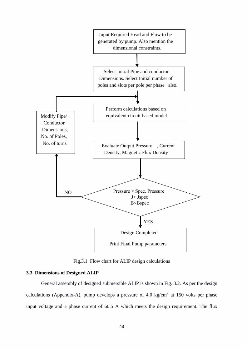
43
Fig.3.1 Flow chart for ALIP design calculations
3.3 Dimensions of Designed ALIP
General assembly of designed submersible ALIP is shown in Fig. 3.2. As per the design
calculations (Appendix-A), pump develops a pressure of 4.0 kg/cm2 at 150 volts per phase
input voltage and a phase current of 60.5 A which meets the design requirement. The flux
YES
Input Required Head and Flow to be
generated by pump. Also mention the
dimensional constraints.
Select Initial Pipe and conductor
Dimensions. Select Initial number of
poles and slots per pole per phase also.
Perform calculations based on
equivalent circuit based model
Evaluate Output Pressure , Current
Density, Magnetic Flux Density
Design Completed
Print Final Pump parameters
Pressure ≥ Spec. Pressure
J< Jspec
B<Bspec
Modify Pipe/
Conductor
Dimens ions,
No. of Poles,
No. of turns
NO

44
density in the core is within the permissible limit of 1.2 T. The specification of developed
submersible ALIP is given in Table 3.1.
Fig. 3.2 General assembly of submersible ALIP
Table 3.1 Specifications of submersible ALIP
Designation of Pump Submersible ALIP
Normal Flow rate 2.0 m3/h
Head to be Developed at Nominal
flow Rate and Temperature 0.4 MPa
Rated Voltage 150 V, 3 Phase, 50 Hz
kVA Rating 30 kVA
Line Current 105 Amps (phase current – 60 Amp)
Insulation Mineral Insulated SS Sheathed
Copper Conductor
Cooling No external cooling required
Maximum Sodium Temperature
Permissible 873 K(600 °C)
Normal Sodium Temperature 473K (200 °C)
Shut off head of pump 0.5 MPa
Duct design Pressure 1.2 MPa at 873 K
Type of ALIP Once Through Type
45
3.4 Simulation of Submersible ALIP
This section deals with simulation of submersible annular linear induction pump. In
order to house the MI cable winding 1.0 mm thick SS plates are provided in the slots. The
design of submersible ALIP was done using the equivalent circuit approach. Finite element
based simulation was carried out to compare with the analytical design calculations. The
convergence of the two diverse techniques helps in enhancing the confidence for building the
pump design.
Following assumptions were made in the finite element model of ALIP.
i. 2-D axisymmetry was assumed. The central core and duct are axisymmetric but the stator
lamination stacks are not. Though, the arrangement of stator laminations is such that
when the magnetic flux enters the sodium duct, it is axisymmetric. Therefore, the
assumption of axisymmetry is justified.
ii. The individual conductors and turns of MI cable winding were not modeled, rather
conductor area and number of turns in each slot were given as input. This implies that the
SS sheath surrounding the copper was not modeled.
iii. The winding was housed in a stainless steel plate housing. This housing was not modeled.
iv. The MI cable has additional length of leads (approximately 20 m on both start and finish
ends of the winding). This lead length was not included. This means that the actual
winding will have more resistance than that in the model. This additional length of the
winding has been added in the winding resistance in the equivalent circuit based
calculations.
v. Magnetic properties of the materials were assumed to be linear. This means that B-H
curves of material used is linear. Magnetic properties are assumed to be independent of
temperature though, electrical conductivity of material varies with temperature in the
simulation model.

46
vi. Grain orientation of magnetic material was not modeled.
3.4.1 Geometric details of finite element based model
The geometry of the pump as modeled in COMSOL is shown in Fig. 3.3. The pump has been
modeled as an axisymmetric object.
Fig. 3.3: Simulation model in COMSOL
3.4.2 Applicable equations
The simulation model solves both the electromagnetic and turbulent flow equations but
not simultaneously. The simulation of ALIP has been done in the following three stages in
COMSOL.
a. First Navier Stokes equations are solved for flow (in Turbulent Region) and the velocity
profile is obtained for the specified flow.
47
b. Electromagnetic force is computed for the velocity obtained in a.
c. Flow equations are once again solved for the electromagnetic force obtained in b and
the pressure developed at the pump exit is obtained.
The simulation of ALIP has been done in time harmonic domain and coupled with steady state
hydrodynamic Navier Stokes equations. Following are the applicable Maxwell’s equations.
J H (3.1)
t
B E
(3.2)
B)Vσ(EJ (3.3)
0.B (3.4)
BJfEM (3.5)
Navier Stokes equation for steady state flow is given by
EMfVηp-) V(Vρ (3.6)
For incompressible steady state flow, the mass conservation equation becomes
0V).(ρ (3.7)
The coupling between electromagnetic field and the fluid flow is simulated by adding the
volume electromagnetic force fEM to the force term of the Navier Stokes equation. The effect of
velocity on the magnetic field is simulated by adding the term BV to the ohms’ law σEJ .
3.4.3 Boundary conditions
3.4.3.1 Electromagnetic Boundary Conditions
For electromagnetic boundary conditions the central axis is assigned axisymmetry
boundary condition where as the outer boundaries are assigned magnetic insulation boundary
condition which makes the magnetic field tangential to the outer boundary or in other words the
magnetic field does not cross the outer boundary. The outer boundary is a rectangular box

48
whose edges are 250 mm away from the pump outer boundary. Since the simulation is in low
frequency range (<1000Hz) this distance was found to be acceptable.
COMSOL feature of multi-turn domain was used to model the coils with specified
number of turns. The conductivity of the conductor material (i.e. copper) was set as per
temperature. Voltage was given as input to the coil. All the 3-phase coils were excited by the
same voltage but displaced in phase by 120° electrical.
3.4.3.2 Fluid flow Boundary Conditions
The central axis was assigned axisymmetry boundary condition. The walls of the pipe
were assigned logarithmic wall function to account for the variation of flow velocity in
turbulent region. The fluid flow has been solved using the k-ε turbulence model. The inlet was
assigned a pressure of zero Pascal and the outlet boundary was assigned the velocity
corresponding to the desired flow rate.
3.4.4 Coupling Between Electromagnetic and Fluid Models
The electromagnetic force produced in the liquid metal is coupled to the fluid flow by
adding the electromagnetic force to the Navier-Stokes equation as a volume force. Then the
resultant pressure obtained from solving Navier Stokes equation yields the pressure developed
by the pump. The hydraulic losses are already accounted in the Navier Stokes equation.
In COMSOL simulation first flow is simulated without the electromagnetic field and
the velocity profile in the annular duct region is obtained. Thereafter, the electromagnetic force
corresponding to the obtained velocity is computed. In the third stage, Navier-Stokes equation
is solved once again and the pressure developed by the pump is obtained. Thus, the effect of
velocity profile and end effects due to motion of conducting liquid metal in magnetic field are
accounted in the simulation model.
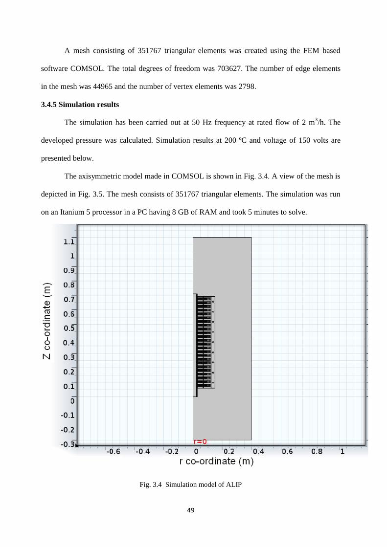
49
A mesh consisting of 351767 triangular elements was created using the FEM based
software COMSOL. The total degrees of freedom was 703627. The number of edge elements
in the mesh was 44965 and the number of vertex elements was 2798.
3.4.5 Simulation results
The simulation has been carried out at 50 Hz frequency at rated flow of 2 m3/h. The
developed pressure was calculated. Simulation results at 200 ºC and voltage of 150 volts are
presented below.
The axisymmetric model made in COMSOL is shown in Fig. 3.4. A view of the mesh is
depicted in Fig. 3.5. The mesh consists of 351767 triangular elements. The simulation was run
on an Itanium 5 processor in a PC having 8 GB of RAM and took 5 minutes to solve.
Fig. 3.4 Simulation model of ALIP
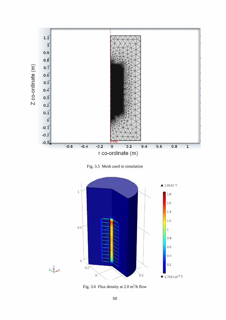
50
Fig. 3.5 Mesh used in simulation
Fig. 3.6 Flux density at 2.0 m3/h flow
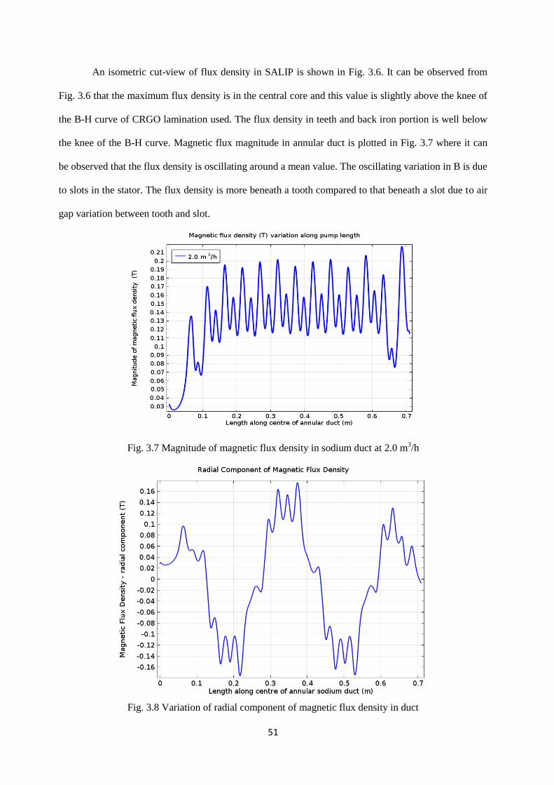
51
An isometric cut-view of flux density in SALIP is shown in Fig. 3.6. It can be observed from
Fig. 3.6 that the maximum flux density is in the central core and this value is slightly above the knee of
the B-H curve of CRGO lamination used. The flux density in teeth and back iron portion is well below
the knee of the B-H curve. Magnetic flux magnitude in annular duct is plotted in Fig. 3.7 where it can
be observed that the flux density is oscillating around a mean value. The oscillating variation in B is due
to slots in the stator. The flux density is more beneath a tooth compared to that beneath a slot due to air
gap variation between tooth and slot.
Fig. 3.7 Magnitude of magnetic flux density in sodium duct at 2.0 m3/h
Fig. 3.8 Variation of radial component of magnetic flux density in duct

52
Variation in radial component of magnetic flux density is shown in Fig. 3.8. The field is having
a predominant fundamental component along with harmonics imposed due to slots. From the variation
of magnetic field it can also be observed that the winding produces 4 magnetic poles.
Fig. 3.9 Contour plot of radial component of magnetic flux density
Contour plot of radial component of magnetic flux density is shown in Fig. 3.9 where it
is observed that the maximum radial magnetic flux density is 1.2 T well below the knee of the
B-H curve. The arrow plot of Fig. 3.10 depicts the flow of magnetic flux from tooth to central
core and from central core back to tooth. Crowding of flux (higher flux densities) is observed in
the central core region compared to that in the teeth region.

53
Fig. 3.10 Arrow plot depicting the magnetic flux density lines
Fig. 3.11 Model predicted current density in sodium duct

54
Induced current density plot in annular sodium duct is shown in Fig. 3.11. The variation
is approximately sinusoidal in nature. The interaction of this induced current with magnetic
field produced by the winding results in volume force on liquid sodium as per the equation 3.5.
The volume force generation in the sodium duct is shown in Fig. 3.12. The negative
volume force at the entry and exit of the pump is due to the so called “end- effects” which
occur due to discontinuity in magnetic field. These effects are not present in an induction motor
since the magnetic circuit is closed. The oscillation in force along the length is due to the
presence of slots and teeth. These oscillations do not result in any observable fluctuations in
sodium flow due to the inertia of sodium and it flows as per the average force produced.
The developed pressure, as a result of this volume force on liquid sodium is plotted and
shown in Fig. 3.13. It can be observed that the pressure increases linearly with length of the
pump. The variation in output pressure at different flow rates is shown in Fig. 3.14. The
reduction in pressure at higher flow rates is due to the end-effects which gain prominence at
higher liquid metal velocity.
Fig. 3.12 Volume force in sodium duct at 2.0 m3/h

55
Fig. 3.13 Pressure development in sodium duct at 2.0 m3/h
Fig. 3.14 Variation in developed pressure with flow
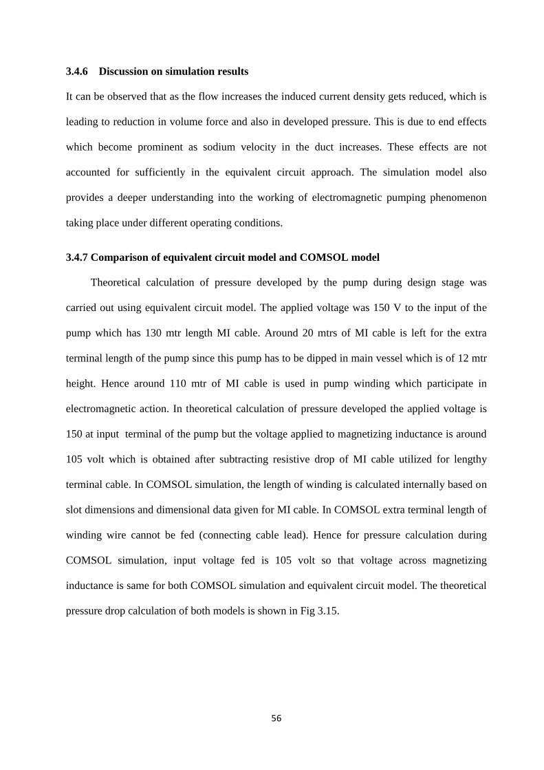
56
3.4.6 Discussion on simulation results
It can be observed that as the flow increases the induced current density gets reduced, which is
leading to reduction in volume force and also in developed pressure. This is due to end effects
which become prominent as sodium velocity in the duct increases. These effects are not
accounted for sufficiently in the equivalent circuit approach. The simulation model also
provides a deeper understanding into the working of electromagnetic pumping phenomenon
taking place under different operating conditions.
3.4.7 Comparison of equivalent circuit model and COMSOL model
Theoretical calculation of pressure developed by the pump during design stage was
carried out using equivalent circuit model. The applied voltage was 150 V to the input of the
pump which has 130 mtr length MI cable. Around 20 mtrs of MI cable is left for the extra
terminal length of the pump since this pump has to be dipped in main vessel which is of 12 mtr
height. Hence around 110 mtr of MI cable is used in pump winding which participate in
electromagnetic action. In theoretical calculation of pressure developed the applied voltage is
150 at input terminal of the pump but the voltage applied to magnetizing inductance is around
105 volt which is obtained after subtracting resistive drop of MI cable utilized for lengthy
terminal cable. In COMSOL simulation, the length of winding is calculated internally based on
slot dimensions and dimensional data given for MI cable. In COMSOL extra terminal length of
winding wire cannot be fed (connecting cable lead). Hence for pressure calculation during
COMSOL simulation, input voltage fed is 105 volt so that voltage across magnetizing
inductance is same for both COMSOL simulation and equivalent circuit model. The theoretical
pressure drop calculation of both models is shown in Fig 3.15.
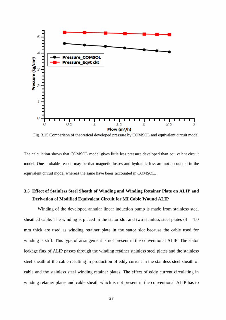
57
Fig. 3.15 Comparison of theoretical developed pressure by COMSOL and equivalent circuit model
The calculation shows that COMSOL model gives little less pressure developed than equivalent circuit
model. One probable reason may be that magnetic losses and hydraulic loss are not accounted in the
equivalent circuit model whereas the same have been accounted in COMSOL.
3.5 Effect of Stainless Steel Sheath of Winding and Winding Retainer Plate on ALIP and
Derivation of Modified Equivalent Circuit for MI Cable Wound ALIP
Winding of the developed annular linear induction pump is made from stainless steel
sheathed cable. The winding is placed in the stator slot and two stainless steel plates of 1.0
mm thick are used as winding retainer plate in the stator slot because the cable used for
winding is stiff. This type of arrangement is not present in the conventional ALIP. The stator
leakage flux of ALIP passes through the winding retainer stainless steel plates and the stainless
steel sheath of the cable resulting in production of eddy current in the stainless steel sheath of
cable and the stainless steel winding retainer plates. The effect of eddy current circulating in
winding retainer plates and cable sheath which is not present in the conventional ALIP has to

58
be accounted while predicting theoretical performance of the ALIP. The presence of two layers
of stainless steel sheath of winding and two winding retainer plates are approximated as
presence of total six stainless steel plates of 1.0 mm thick present in the slot for determining
eddy current effect. The winding arrangement in the slot is shown in Fig. 3.16. To account
effect of eddy current in winding and retainer plate, the equivalent circuit of ALIP is modified
as shown in Fig. 3.17 and theoretical performance is evaluated based on modified equivalent
circuit [23].
3.5.1 Calculation of eddy current in sheath and plates and its equivalent resistance
referred to primary
ϕl is the leakage flux in the slot which causes eddy current in the sheath and plate.
ϕl as given below can be obtained from equations 2.15 & 2.16 of chapter 2.
11
13807l
D
D
3
DIN (3.8)
Where N7 = 22, I= 60 A, µ0= 4π x 10-7
, D8= 62.48x10⁻³
m, D13=77x10-3
m, D11=16x10-3
m
16
48.62
3
10771046022 77
l
wb1022.5 4
l
V16399.05021022.5e 4
lrms (3.9)
Resistance of retainer disc is calculated as follows
Area
LengthRdisc (3.10)
OD of Disc = 230.0 mm
ID of Disc = 60.0 mm
Therefore, inner radius of disc, r1=30.0 mm
Outer radius of disc, r2=115.0 mm
Width of disc for current flow= r2-r1=85.0 mm
59
Mean Radius 2
rrr 121 (3.11)
Mean Radius = 72.5 mm
Mean Length = 2 π X 72.5 x 10-3
= 455.5 x 10⁻³
m (3.12)
area = thickness x height
area = 1 x 10 -3
x 85 x 10 -3
= 85.0 x 10⁻⁶
m2
3
6
36
disc 10971.51085
105.455101144.1
Area
LengthR (3.13)
Amp46.2710971.5
16399.0
R
eI
3
disc
rmseddy (3.14)
Loss in one Disc
watt5.410971.546.27RI 32
disc
2
eddy (3.15)
There are 8 slots per phase having 6 equivalent discs (this includes SS discs and sheathed
cables)
Therefore, Eddy Current Loss per phase = 4.5 x 6 x 8 = 216.0 watt (3.16)
Total mmf in all discs in a slot = 6 x 27.46 = 164.76 Amp Turn (3.17)
Total mmf of disc in per phase = 164.76 x 8 = 1318 Amp Turn (3.18)
No. of Turns in primary per phase = Nsc X Ieq eddy current in primary = 1318 (3.19)
Ieq eddy current in primary 176
1318 = 7.5 Amp (3.20)
'
eddyR = Resistance of disc reflected to primary side
216R5.7 '
eddy
2.0 (3.21)
84.3R '
eddy
'
eddyR is designated as Rsp in the modified equivalent circuit. Rsp represents resistance of SS
sheath of cable and retainer plate in the slot referred to primary.

60
3.5.2 Calculation for effect of opposing MMF due to eddy current
rms
11
13870rms I
D
DDN
3e (3.22)
eddy
rms
11
13870eddy
R
I
D
DDN
3I (3.23)
The eddy currents oppose the main mmf in the slot
Therefore, the net effective mmf in the slot
Net Slot MMF eddy
rms
11
13870prms7
R
I
D
DDN
3NIN (3.24)
Np = No. of equivalent SS plates = 6
Net Slot MMF rms7
eddy11
1380p IN
R
1
D
DD
3N1 (3.25)
For the dimensional parameters of the designed Submersible ALIP
,104 7
0 ,m1048.62D 3
8 ,m100.77D 3
13,m100.16D 3
11
,10971.5R 3
eddy Np=6
Therefore, Net Slot MMF
rms733
337
IN10971.5
1
1016
50210771048.62
3
10461
Net Slot MMF = rms7rms7 IN875.0IN)1249.01( (3.26)
This implies that the effective number of primary turns in the slots becomes 87.5 % of the
wound turns due to the effect of eddy currents in the stator winding as well as in the retainer
plates. Theoretical performance of the pump is calculated based on this effective number of
primary turns in the slot. While calculating the performance, the i2R loss in the equivalent
sheath plates is also taken into account. Hence, based on the effect of sheath plate, the
equivalent circuit of the pump is modified and shown in Fig. 3.17.

61
Fig. 3. 17 Modified equivalent circuit of ALIP for taking into account the losses taking place
in SS sheath of MI cable and in SS retainer plates.
View of MI cable winding of Submersible
ALIP
Zoomed view depicting retainer plates & MI cable
winding
Equivalent winding with MI cable sheath replaced by
SS plate
Fig. 3.16 Winding arrangement in the slot
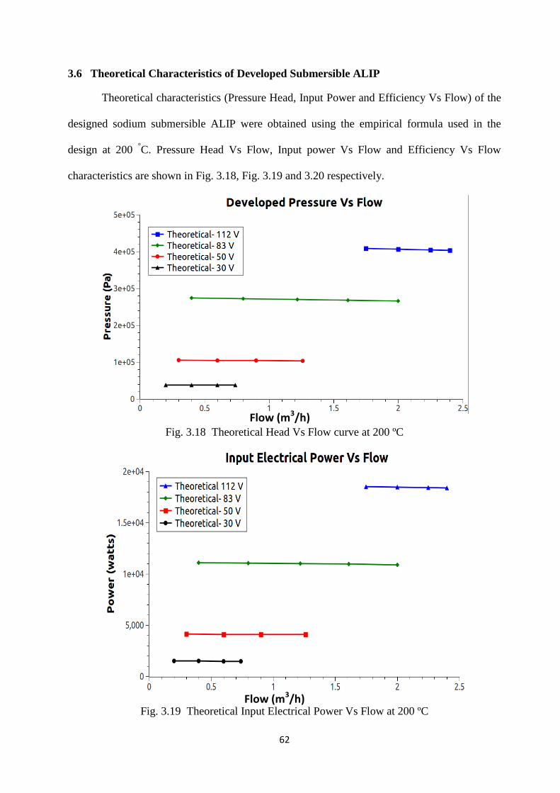
62
3.6 Theoretical Characteristics of Developed Submersible ALIP
Theoretical characteristics (Pressure Head, Input Power and Efficiency Vs Flow) of the
designed sodium submersible ALIP were obtained using the empirical formula used in the
design at 200 °C. Pressure Head Vs Flow, Input power Vs Flow and Efficiency Vs Flow
characteristics are shown in Fig. 3.18, Fig. 3.19 and 3.20 respectively.
Fig. 3.18 Theoretical Head Vs Flow curve at 200 ºC
Fig. 3.19 Theoretical Input Electrical Power Vs Flow at 200 ºC
Flow (m3/h)
Flow (m3/h)
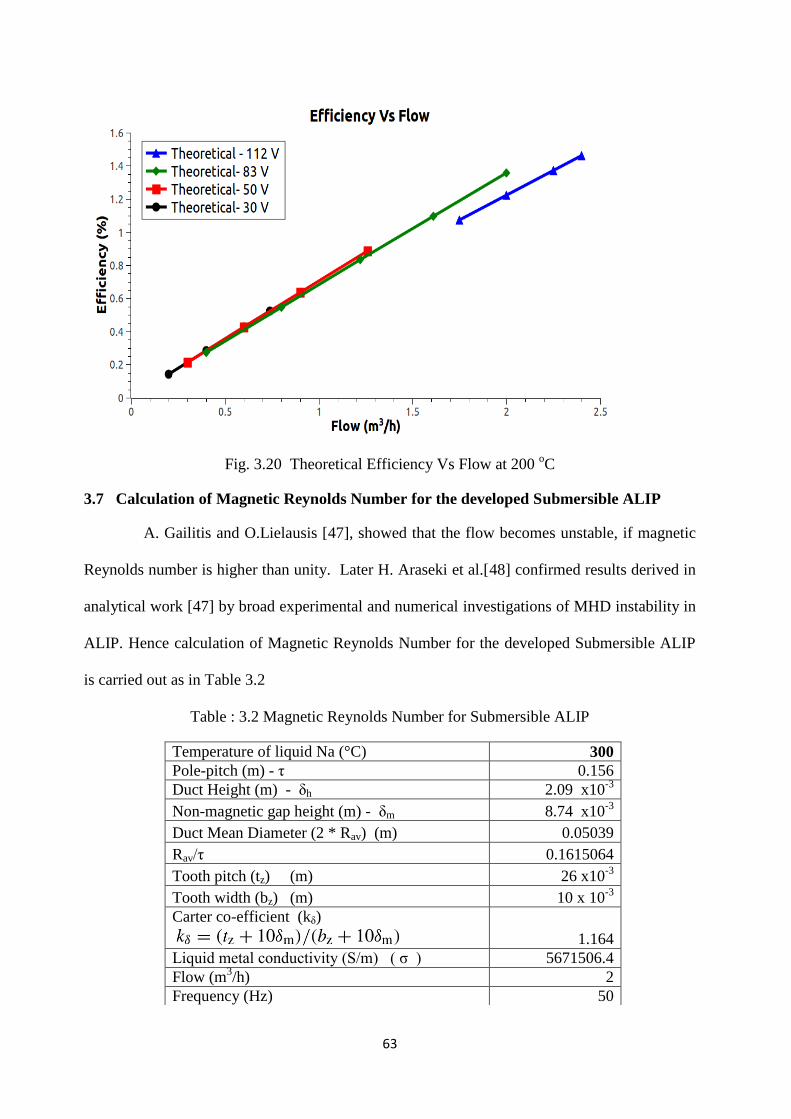
63
Fig. 3.20 Theoretical Efficiency Vs Flow at 200 oC
3.7 Calculation of Magnetic Reynolds Number for the developed Submersible ALIP
A. Gailitis and O.Lielausis [47], showed that the flow becomes unstable, if magnetic
Reynolds number is higher than unity. Later H. Araseki et al.[48] confirmed results derived in
analytical work [47] by broad experimental and numerical investigations of MHD instability in
ALIP. Hence calculation of Magnetic Reynolds Number for the developed Submersible ALIP
is carried out as in Table 3.2
Table : 3.2 Magnetic Reynolds Number for Submersible ALIP
Temperature of liquid Na (°C) 300
Pole-pitch (m) - η 0.156
Duct Height (m) - δh 2.09 x10⁻³
Non-magnetic gap height (m) - δm 8.74 x10⁻³
Duct Mean Diameter (2 * Rav) (m) 0.05039
Rav/η 0.1615064
Tooth pitch (tz) (m) 26 x10-3
Tooth width (bz) (m) 10 x 10-3
Carter co-efficient (kδ)
1.164
Liquid metal conductivity (S/m) ( ζ ) 5671506.4
Flow (m3/h) 2
Frequency (Hz) 50

64
It is seen from calculation that Magnetic Reynolds Number is not higher than unity.
Theoretical Pressure Vs Flow characteristic obtained as shown in Fig. 3.18 shows dP/dQ
negative. Other condition for unstable flow is that dP/dQ should be positive[47]. Since
Magnetic Reynolds Number is not higher than unity and also dP/dQ is negative, it is concluded
that developed flow will not become unstable. Theoretically it is foreseen that pump will
develop stable flow in its operating region.
3.8 Summary
Sodium submersible ALIP having 2.0 m3/h flowrate and 4.0 kg/cm
2 pressure head was
designed. A lateral dimension of 400.0 mm was achieved. The winding of pump is made of
stainless steel sheathed mineral insulated cable capable of withstanding 550 °C. Its
performance was evaluated using FEM analysis. Comparison of theoretical pressure developed
by the designed pump using equivalent circuit model and by the FEM analysis using COMSOL
was carried out. The effect of eddy currents in the sheath of winding on the pump performance
was carried out. Modification of the equivalent circuit to take account of effect of eddy currents
is brought out and this is an important aspect in this research work. Theoretical pump
characteristics are also obtained using empirical formula used in the design. Theoretical
calculation has indicated that pump flow will be stable and pump instability is not predicted.
Angular Frequency (ω) 314.15
synchronous velocity (m/s) 15.6
flow velocity (m/s) 1.6784156
Slip (s) 0.8924093
magnetic permeability (μ) 1.257 x 10⁻⁶
α=π/η (i.e. π/pole pitch) 20.137821
Magnetic Reynolds Number,
1.00


65
CHAPTER- 4
ANNULAR LINEAR INDUCTION PUMP DEVELOPMENT AND
MANUFACTURING
Annular linear induction pump having stator winding made from mineral insulated
stainless steel sheathed cable capable of withstanding high temperature sodium atmosphere as
per the research aim was manufactured in three stages. In first stage, a compact three phase
induction motor with mineral insulated cable winding was developed to prove the concept of
motor winding made from mineral insulated stainless steel sheathed cable. In second stage,
mineral insulated stainless steel sheathed cable of 6 mm diameter required as per designed
ALIP was developed. In third stage, compact stainless steel enclosed ALIP having stator
winding made from mineral insulated stainless steel sheathed cable as per design was
developed.
4.1 Development of Induction Motor with MI Cable Winding (Stage-1)
In the first stage, design, fabrication and testing of a compact three phase 50 W, 110
V, 3600 rpm squirrel cage induction motor with Mineral Insulated (MI) cable winding were
carried out in two phases. In the first phase, one compact induction motor with class-H
insulation winding was developed. In second phase, stator windings of the motor were
replaced with MI cable winding to make it suitable for operation in high temperature
environment.
4.2. Design of Induction Motor with class H insulation
4.2.1 Induction motor design
One 50 W, 3ø, 110 V, 3600 rpm, squirrel cage induction motor was designed as per
technical details given in Table. 4.1. The overall dimensions of the motor were fixed as per
process requirements. CRNGO lamination of 0.35 mm thickness was used to form the stator
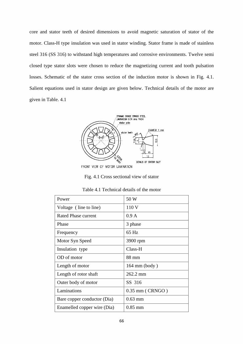
66
core and stator teeth of desired dimensions to avoid magnetic saturation of stator of the
motor. Class-H type insulation was used in stator winding. Stator frame is made of stainless
steel 316 (SS 316) to withstand high temperatures and corrosive environments. Twelve semi
closed type stator slots were chosen to reduce the magnetizing current and tooth pulsation
losses. Schematic of the stator cross section of the induction motor is shown in Fig. 4.1.
Salient equations used in stator design are given below. Technical details of the motor are
given in Table. 4.1
Fig. 4.1 Cross sectional view of stator
Table 4.1 Technical details of the motor
Power 50 W
Voltage ( line to line) 110 V
Rated Phase current 0.9 A
Phase 3 phase
Frequency 65 Hz
Motor Syn Speed 3900 rpm
Insulation type Class-H
OD of motor 88 mm
Length of motor 164 mm (body )
Length of rotor shaft 262.2 mm
Outer body of motor SS 316
Laminations 0.35 mm ( CRNGO )
Bare copper conductor (Dia) 0.63 mm
Enamelled copper wire (Dia) 0.85 mm
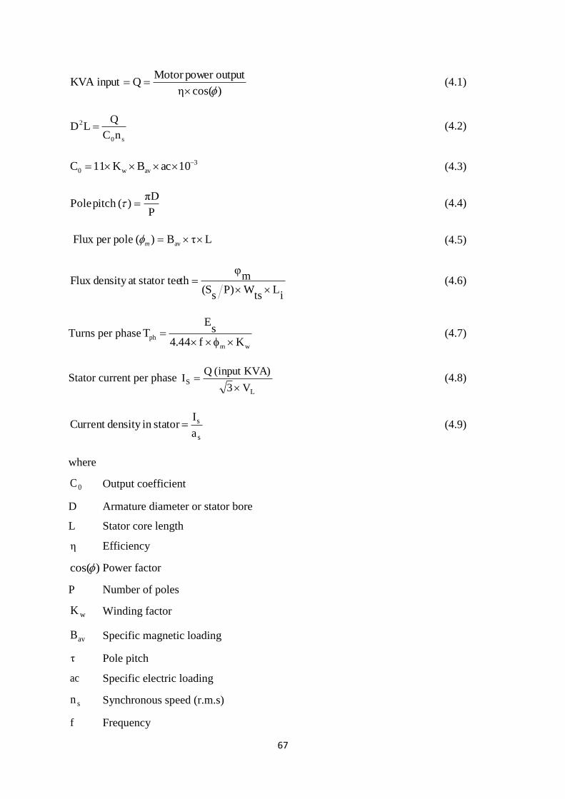
67
)cos(η
outputpower Motor QinputKVA
(4.1)
s0
2
nC
QLD (4.2)
3
avw0 10acBK11C (4.3)
P
πD)(pitch Pole (4.4)
LτB)(poleper Flux av m (4.5)
iL
tsW)P
sS(
mφ
thstator teeat density Flux
(4.6)
Turns per phasewm
phKf44.4
sE
T
(4.7)
Stator current per phase L
SV 3
KVA)(input QI
(4.8)
s
s
a
Istatorin density Current (4.9)
where
0C Output coefficient
D Armature diameter or stator bore
L Stator core length
η Efficiency
)cos( Power factor
P Number of poles
wK Winding factor
avB Specific magnetic loading
τ Pole pitch
ac Specific electric loading
sn Synchronous speed (r.m.s)
f Frequency

68
sS Number of stator slots
tsW Width of tooth
iL Net iron length
LV Line voltage
sI Stator line current
CRNGO lamination of 0.35 mm thickness, die cast Aluminium rotor bar and end
rings were used in rotor of the motor. Rotor with seventeen semi closed rectangular slots was
chosen to avoid magnetic locking, for better overload capacity and high starting torque.
Rotor cross section is shown in Fig. 4.2 and Fig. 4.3. Rotor bars shape chosen helps in higher
starting torque and lower operating losses. Pictorial view of the developed low power
induction motor is shown in Fig. 4.4. Equations used for rotor design are given below.
DL20.2lg (4.10)
gsir l2DD (4.11)
Where
gl Length of air gap
rD Diameter of rotor
siD Inner diameter of stator
rS
D gapair at pitch slot Rotor
(4.12)
rS
)cos(×Is×Tph×Kws×s
m×2
bI
(4.13)
b
bI
ba
(4.14)
ir
m
Lhrotor teetP
S
φth)(Rotor tee
maxB
(4.15)

69
P
IS
eI br
(4.16)
e
eI
ea
(4.17)
Where
bI Rotor bar current
ba Area of rotor bar
eI End ring current
ea Area of end ring
b Current density in rotor bar
Fig. 4.2 Cross sectional view of rotor
Fig. 4.3 Cross sectional view of rotor slot

70
Fig. 4.4 Low power induction motor
The induction motor developed was tested. The test set up for measuring various
electrical parameters of the motor is shown in Fig. 4.5. Input current and power
measurements were carried out at no load and locked rotor conditions.
Fig. 4.5 Test set up for induction motor.
4.3. Design of High Temperature Induction Motor with Mineral Insulated Cable
Winding
After successful testing of the compact motor, the work on development of high
temperature induction motor was taken up. The conventional winding of the developed motor
was replaced with mineral insulated cable winding. Stator winding of the motor was
fabricated with Mineral Insulated (MI) cables of 1.0 mm outer diameter. MI cable consists of
Stainless Steel (SS) sheath, MgO powder and copper conductor at the center of the cable. The
MI cable does not undergo any major changes in the radiation field and being used in various
sensors for high temperature application up to 550 °C. Use of MI cable in electromagnets of

71
the shut down systems submerged in sodium and operating at high temperature is a classical
example of suitability of MI cable under hostile environments.
4.3.1 Properties and testing of MI cable
4.3.1.1 Properties of MI cable
MI cable consists of central copper conductor concentrically placed inside a SS tube.
SS tube and central copper conductor are electrically insulated by a densly packed high pure
Magnesium Oxide. The SS sheath of required thickness on the cable is formed by drawing a
single tube. Both ends of the cable are sealed using epoxy sealants. MI cable was tested for
conductor resistance, insulation resistance at room and high temperatures, SS sheath integrity
and high voltage.
4.3.1.2 Current carrying capacity test on MI cable
In order to utilize the MI cable for high current density applications, experiment was
conducted to determine the current carrying capacity of the MI cable of 1.5 mm outer
diameter and 0.8 mm conductor diameter. The schematic of the test set-up is shown in Fig.
4.6. The pictorial view of the test set-up is shown in Fig. 4.7, Fig. 4.8 and Fig. 4.9. A
thermocouple (K type) was used to monitor the temperature of the MI cable coil. A rheostat
with ratings of 50 Ω and 10A was used in series with MI cable coil to vary the current in the
coil.
Fig. 4.6 Schematic of test set-up for MI cable
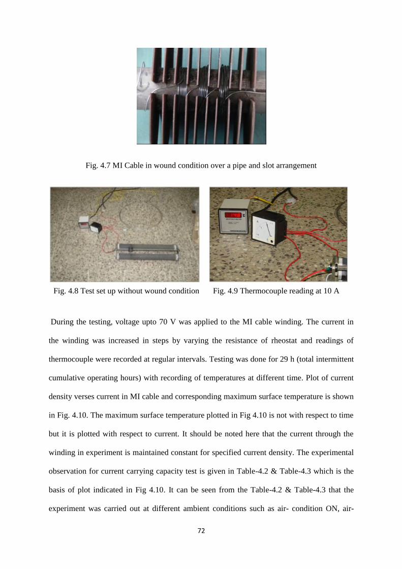
72
Fig. 4.7 MI Cable in wound condition over a pipe and slot arrangement
During the testing, voltage upto 70 V was applied to the MI cable winding. The current in
the winding was increased in steps by varying the resistance of rheostat and readings of
thermocouple were recorded at regular intervals. Testing was done for 29 h (total intermittent
cumulative operating hours) with recording of temperatures at different time. Plot of current
density verses current in MI cable and corresponding maximum surface temperature is shown
in Fig. 4.10. The maximum surface temperature plotted in Fig 4.10 is not with respect to time
but it is plotted with respect to current. It should be noted here that the current through the
winding in experiment is maintained constant for specified current density. The experimental
observation for current carrying capacity test is given in Table-4.2 & Table-4.3 which is the
basis of plot indicated in Fig 4.10. It can be seen from the Table-4.2 & Table-4.3 that the
experiment was carried out at different ambient conditions such as air- condition ON, air-
Fig. 4.8 Test set up without wound condition Fig. 4.9 Thermocouple reading at 10 A

73
condition OFF, Fan ON, Fan OFF etc. but by maintaining same current value. The
maxiumum temperature reading obtained is during no fan and no air-condition operation. It is
observed that MI cable is able to carry currents with current density up to 20 A/mm2, which is
much higher than conventional motor winding cable capability (2 to 5 A/mm2).
Fig. 4.10 Current carrying capacity of MI cable
Table 4.2 : Tests on 1.5 mm MI cable roll
Sl. No. Time Current (Amps) Current Density
(Amp/mm2)
Temperature (° C) Ambient Conditions
1 14:25 4 7.96 38 NO FAN NO AC
2 14:40 4 7.96 43 NO FAN NO AC
3 14:50 4 7.96 43 NO FAN NO AC
4 16:20 4 7.96 43 NO FAN NO AC
Next Day
5 09:30 5 9.95 39 NO FAN NO AC
6 09:40 5 9.95 53 NO FAN NO AC
7 09:45 5 9.95 56 NO FAN NO AC
8 09:55 5 9.95 54 AC only
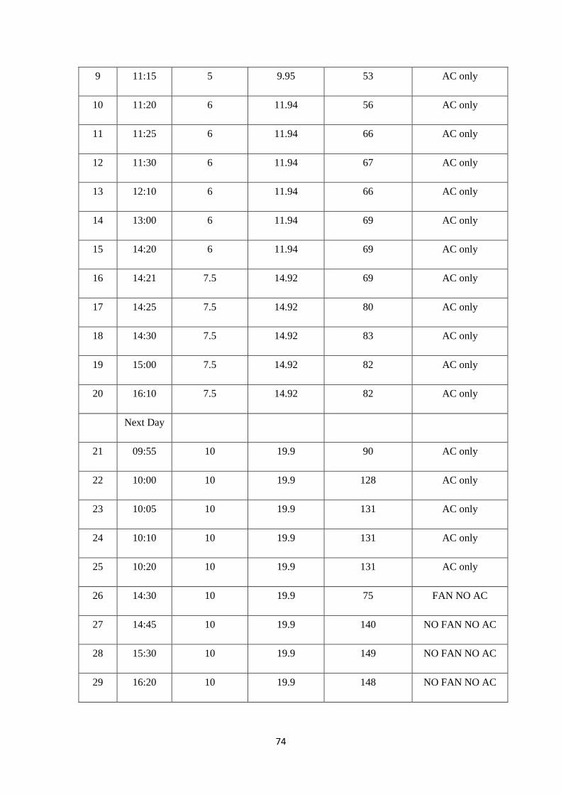
74
9 11:15 5 9.95 53 AC only
10 11:20 6 11.94 56 AC only
11 11:25 6 11.94 66 AC only
12 11:30 6 11.94 67 AC only
13 12:10 6 11.94 66 AC only
14 13:00 6 11.94 69 AC only
15 14:20 6 11.94 69 AC only
16 14:21 7.5 14.92 69 AC only
17 14:25 7.5 14.92 80 AC only
18 14:30 7.5 14.92 83 AC only
19 15:00 7.5 14.92 82 AC only
20 16:10 7.5 14.92 82 AC only
Next Day
21 09:55 10 19.9 90 AC only
22 10:00 10 19.9 128 AC only
23 10:05 10 19.9 131 AC only
24 10:10 10 19.9 131 AC only
25 10:20 10 19.9 131 AC only
26 14:30 10 19.9 75 FAN NO AC
27 14:45 10 19.9 140 NO FAN NO AC
28 15:30 10 19.9 149 NO FAN NO AC
29 16:20 10 19.9 148 NO FAN NO AC

75
Table 4.3 : Tests on 1.5 mm MI cable in wound condition
Sl. No. Time Current (Amps) Current Density
(Amp/mm2)
Temperature (° C) Ambient Conditions
1 15:10 6 11.94 32 NO FAN NO AC
2 15:35 6 11.94 48 NO FAN NO AC
3 15:45 6 11.94 49 NO FAN NO AC
4 15:46 10 19.9 58 NO FAN NO AC
5 15:55 10 19.9 77 NO FAN NO AC
6 16:25 10 19.9 87 NO FAN NO AC
7 17:00 10 19.9 87 NO FAN NO AC
4.3.2 High temperature induction motor with MI cable
The designed stator frame and rotor was used for high temperature induction motor,
except the stator winding, which is now made from MI cable. The stator outer diameter and
length was maintained same due to process requirements.
4.3.2.1 Motor design
Apart from stator windings, all other specifications of motor mentioned in Section4.2
were kept same as given in Table. 4.1. Stator windings were formed with SS sheathed MI
cable of 1.0 mm diameter with central copper conductor of 0.35 mm. Photographs of low
power motor with MI cable winding are shown in Fig. 4.11, Fig. 4.12 and Fig. 4.13.

76
Fig. 4.11 Low power induction motor with MI cable
With reduction in space factor by 50 % because of usage of MI cable in stator
windings, only 55 turns per phase were possible. Reduction in number of turns led to increase
in air gap flux for a rated voltage. High flux resulted in high magnetizing current, leading to
higher copper losses and rise in winding temperature. High temperatures in winding did not
affect the reliability of motor due to higher thermal withstand capacity of MI cable stator
winding. Stator was designed for star connection and stator flux value was obtained as per
following equation.
V 63.53
110Ephaseper tageStator vol s (4.18)
Fig. 4.12 Stator of low power
motor with MI cable Fig. 4.13 Motor in open condition

77
Flux per pole for phase voltage of 63.5 V is
wph
sm
KTf4.44
Eφ
(4.19)
Where
phT Turns per phase
wK Winding factor
Wb0.0041890.95555654.44
63.5φm
Magnetic flux density corresponding to the flux per pole given above is 0.6 T.
4.3.3 FEM analysis of high temperature induction motor
FEM analysis of high temperature induction motor was carried out using FEMM code
to check the saturation of various parts of the motor and to predict the rotor torque. Two
dimensional model of induction motor with MI cable was simulated using non linear
ferromagnetic laminated steel BH curves. Magnetic flux density values in various parts of
motors with fixed stator current were simulated and used for predicting torque slip
characteristics using Maxwell stress tensor method [34,35,36,37,38]. Two dimensional model
of high temperature induction motor with dimensions given in Section 2 is shown in Fig.
4.14. Stator and rotor core highlighted in pink color were modeled as silicon steel
laminations. Three phase stator windings are placed in stator as shown in Fig 4.14. Constant
three-phase currents were applied to the stator windings in model. Stator and rotor core were
modeled as silicon steel lamination. The aluminium rotor bars were modeled with a
conductivity of 34.45 MS/m [39]. Following approximations were made for two dimensional
modeling.
Increase in rotor resistance due to increase in temperature during long operations was
neglected.
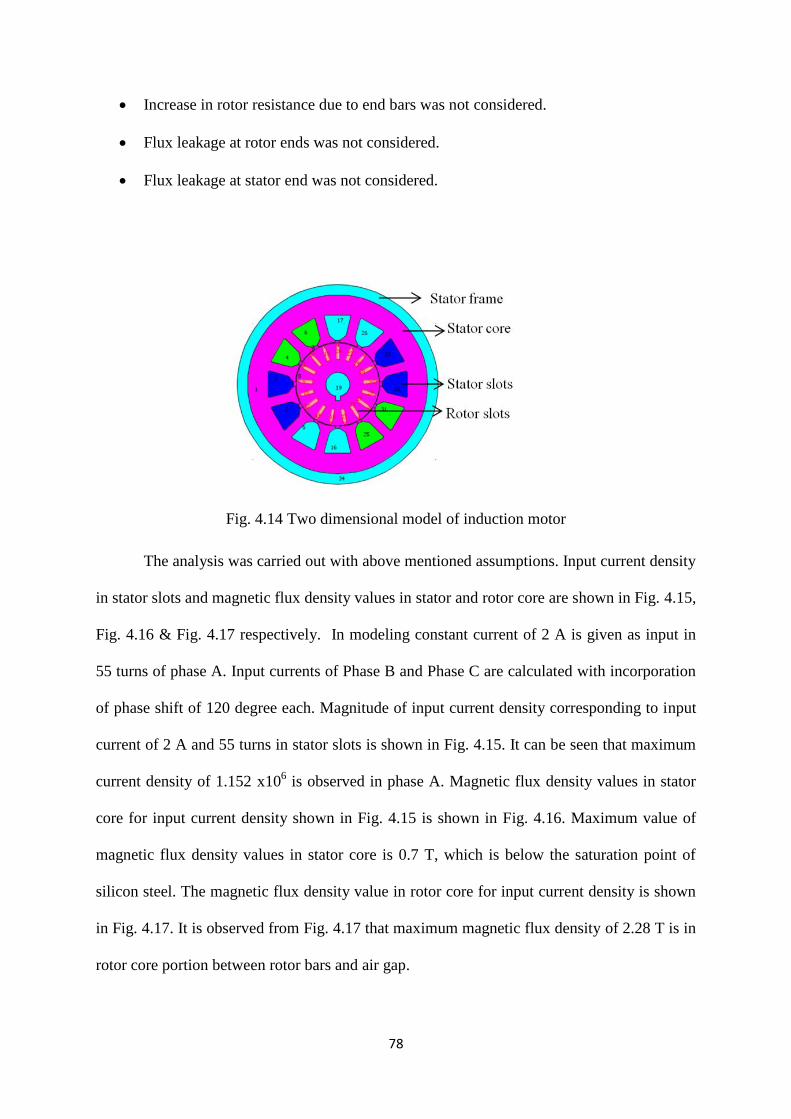
78
Increase in rotor resistance due to end bars was not considered.
Flux leakage at rotor ends was not considered.
Flux leakage at stator end was not considered.
Fig. 4.14 Two dimensional model of induction motor
The analysis was carried out with above mentioned assumptions. Input current density
in stator slots and magnetic flux density values in stator and rotor core are shown in Fig. 4.15,
Fig. 4.16 & Fig. 4.17 respectively. In modeling constant current of 2 A is given as input in
55 turns of phase A. Input currents of Phase B and Phase C are calculated with incorporation
of phase shift of 120 degree each. Magnitude of input current density corresponding to input
current of 2 A and 55 turns in stator slots is shown in Fig. 4.15. It can be seen that maximum
current density of 1.152 x10⁶ is observed in phase A. Magnetic flux density values in stator
core for input current density shown in Fig. 4.15 is shown in Fig. 4.16. Maximum value of
magnetic flux density values in stator core is 0.7 T, which is below the saturation point of
silicon steel. The magnetic flux density value in rotor core for input current density is shown
in Fig. 4.17. It is observed from Fig. 4.17 that maximum magnetic flux density of 2.28 T is in
rotor core portion between rotor bars and air gap.

79
Electromagnetic torque acting on the rotor is calculated using the Maxwell stress
tensor method. Torque verses slip characteristics obtained using FEM analysis for the
designed high temperature induction motor is shown in Fig. 4.18. It is observed that trend of
the torque characteristics is similar to that of the conventional induction motor. The
maximum torque obtained is 0.7 N-m, stable and unstable operating zones are shown in the
curve.
Fig. 4.15 External current density in stator slot (A/mm2)
Fig. 4.16 Magnetic flux density plot in stator (T)
Fig. 4.17 Magnetic flux density plot in rotor (T)

80
Fig.4.18 Torque - slip characteristics
4.3.4 Test results for high temperature induction motor
The induction motor was tested for its rated current of 2 A at 180 ºC. The plot in
Fig. 4.19 shows the rise in temperature with respect to time during operation of the motor.
The temperature rises initially and then stabilizes at 180 °C. The successful running of motor
at 180 ºC proved the design intent. Motor testing above 180 °C was not carried out due to the
temperature limitations of mechanical bearings used in the motor. The designed motor can be
used even for higher temperature operation, if ceramic bearings are used which can withstand
higher temperature.
Fig. 4.19 Surface temperature Vs time.
4.4 Demonstration of Use of MI Cable for Rewinding of Conventional Induction Motor
Concept of stator winding made from mineral insulated stainless steel sheathed cable was
also proved by rewinding the damaged conventional induction motor using mineral insulated

81
stainless steel sheathed cable in place of conventional copper cable. The rewound motor
shown in Fig. 4.20 worked satisfactorily.
Fig. 4.20 Conventional motor winding replaced with MI cable winding
4.5 Development and Testing of Mineral Insulated Stainless Steel Sheathed Cable
for ALIP (Stage II)
Encouraged with the success in development of mineral insulated stainless steel
sheathed cable wound compact induction motor, development of mineral insulated stainless
steel sheathed cable of 6.0 mm size required for sodium submersible ALIP was initiated.
Keeping this in view, specifications were prepared for MI cable to meet the requirement.
After few experimental trials, the MI cable was successfully developed.
4.5.1 Construction details of mineral insulated cable
Mineral insulated stainless steel sheathed cable consists of a central copper conductor
concentrically placed inside an SS tube. Cross-section of the cable is shown in Fig. 4.21 and
its length is 125.0 meters. Figure 4.22 shows the photograph of the develeped MI cable.
Fig.4.21 Cross-section of MI Cable Fig.4.22: View of developed MI cable

82
4.5.2 Tests carried out on MI cable
The following tests were carried out on the MI cable
1. Electrical Resistance Test
2. Cold Insulation Resistance Test
3. Hot Insulation Resistance Test
4. High Voltage Test
5. Radiographic Test
6. Ductility test
7. Cold bend test
The developed MI cable passed all the above tests as per technical specifications.
4.6 Manufacture of Submersible Annular Linear Induction Pump (Stage III)
As part of research work, submersible ALIP was designed and manufactured for
sodium draining from reactor pool. The submersible ALIP consists of following important
parts/sub-assembly.
Pump duct
Lamination and core
Support flange and cover
Coil and winding
The above parts are manufactured as per specifications. Material specification and
inspections followed during manufacturing are enumerated in Appendix- B.
Conventional electrical insulation can withstand temperatures only upto 200 °C
whereas in case of sodium draining from reactor pool, the winding temperature may go as
high as 550 °C. Therefore, it was decided to use mineral insulated (MI) stainless steel
sheathed cable (with MgO insulation). Manufacturing of submersible ALIP differs from
conventional ALIP since a single length of MI cable is needed for making the pump winding.
The stainless steel sheathed cable has lower flexibility than the copper cable and hence to
gain experience in winding mineral insulated stainless steel sheathed cable, a mockup trial
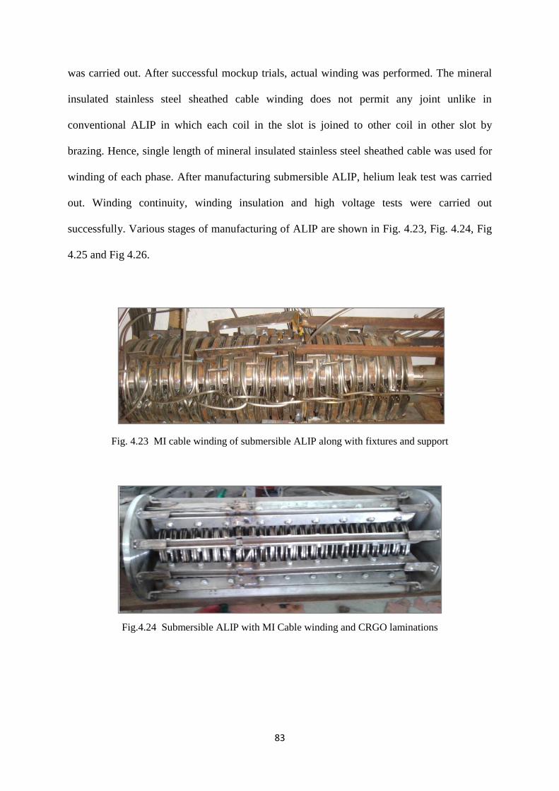
83
was carried out. After successful mockup trials, actual winding was performed. The mineral
insulated stainless steel sheathed cable winding does not permit any joint unlike in
conventional ALIP in which each coil in the slot is joined to other coil in other slot by
brazing. Hence, single length of mineral insulated stainless steel sheathed cable was used for
winding of each phase. After manufacturing submersible ALIP, helium leak test was carried
out. Winding continuity, winding insulation and high voltage tests were carried out
successfully. Various stages of manufacturing of ALIP are shown in Fig. 4.23, Fig. 4.24, Fig
4.25 and Fig 4.26.
Fig. 4.23 MI cable winding of submersible ALIP along with fixtures and support
Fig.4.24 Submersible ALIP with MI Cable winding and CRGO laminations

84
Fig.4.25 Manufactured submersible ALIP with outer stainless steel enclosure
Fig. 4.26 Photograph of manufactured submersible ALIP other view
4.7 Summary
Development of compact sodium submersible ALIP was carried out in three stages. In
the first stage, a compact three phase induction motor with mineral insulated stainless steel
sheath cable winding was developed to prove the concept of new type of winding. In the
second stage, 6.0 mm diameter stainless steel sheathed mineral insulated cable for use in
submersible ALIP was developed. In the third stage, sodium submersible ALIP having stator
winding made from mineral insulated stainless steel sheathed cable for high temperature
application was developed. Helium leak test on pump duct, winding continuity test, insulation
test and high voltage test on each phase winding were carried out for the developed ALIP.


85
CHAPTER-5
PERFORMANCE EVALUATION OF SODIUM SUBMERSIBLE ALIP
5.1 Introduction
Performance evaluation of the developed pump in sodium is needed to validate the
design and qualify it for reactor worthiness. As part of qualification of the pump for
reactor operation, its characteristics (Head, Power and Efficiency Vs Flow) and general
mechanical/ electrical performances are to be evaluated experimentally in a sodium loop.
An experimental facility was designed and erected in existing Bi-Metallic Loop [BIM
loop] at IGCAR [46] for testing the sodium submersible ALIP. The details of the test
setup in BIM loop along with its mechanical, electrical and instrumentation systems are
provided along with operation procedure for testing of the sodium submersible ALIP.
5.2 Description of Sodium Test Facility
The sodium submersible ALIP was installed at cold leg of the Bi-metallic loop in
series with the existing 5.0 m3/h pump in the loop. The suction line of the submersible
ALIP is connected to the loop return line and the discharge is connected to the existing
pump suction through valves. A 1” bypass line was provided for the submersible ALIP
test setup so that the main loop alone can be operated after isolating the test setup. The
flow sheet of the BIM loop with sodium submersible ALIP is shown in Fig. 5.1. The
isometric view of the piping for pump testing setup is shown in Fig. 5.2.
Three manually operated 1” bellow sealed valves were provided in the main flow
path viz. pump bypass (VNa11), pump suction (VNa12) and pump discharge (VNa13).
Bellow sealed valve VNa12 provided in the pump inlet and bellow sealed valve VNa13
provided in the pump discharge regulate the flow through the pump.
Pressure Pots PP-1 and PP-2 were installed at suitable elevations and connected to
the pump suction and discharge lines respectively through ½” Sch. 40 SS pipe lines for

86
measuring pump developed pressure using pressure balance method. Two ½” bellow
sealed valves VNa14 and VNa15 were provided in the pump pressure measuring paths
below Pressure pot PP-1 and Pressure pot PP-2 respectively. The pressure pots were
provided with four resistance type level probes (RTLP) corresponding to Low, Operation
Low, Operation high and Very high sodium levels. The details of the pressure pots are
shown in Fig. 5.3. One permanent magnet type flow meter of range 0-5 m3/h having
sensitivity of 1.96 mV/m3/h was installed in the main flow circuit of the BIM loop. The
flow through the flow meter is equal to the pump flow when purification circuit of BIM is
kept in closed condition.
5.3 Cover Gas System
One argon cover gas system as shown in Fig. 5.4 was provided in the pump test
setup. Inlet and outlet lines of ALIP are connected to the Pressure Pots PP-1 and PP-2
through separate lines. The cover gas header is having separate venting and pressurising
headers. The pressure pots were individually pressurised and vented during pump testing.
Manual and solenoid valves are provided in the cover gas header for pressure regulation
in the pressure pots. The solenoid valves are operated from instrumentation control
panel.
5.3.1 Inert atmosphere inside submersible ALIP casing
The inert atmosphere inside the submersible ALIP casing is ensured for inhibiting
the entry of moisture into the pump and to prevent oxidation of MI cable sheath and
magnetic laminations. For maintaining the inert atmosphere, argon line is provided in MI
cable entry pipe with provision of argon header with argon cylinder.
5.4 Sodium Pressure Measurement Methodology
To measure the differential pressure across the pump suction and delivery, sodium
is allowed to rise in the pressure pots PP-1 and PP-2 when pump under test is in

87
operation. Sodium levels in pressure pots PP-1 and PP-2 are maintained in between
‘Operation Low’ and ‘Operation High’ by regulting the cover gas pressure. The pressure
head developed by the pump is measured through differential pressure at pressure pots
PP-1 and PP-2 at the time when sodium levels in both pressure pots are between
‘Operation Low’ and ‘Operation High’ for the applied voltage and flow. The differential
pressure guage reading is noted down along with flow and applied voltage readings for
plotting the hydraulic characteristic.
5.5 Power Supply Scheme for Testing of Submersible ALIP
Power supply to submersible annular linear induction pump is arranged through a
200 A, 3-phase motorized auto-transformer and a DOL starter. Input voltage of ALIP is
controlled by auto-transformer to vary the pressure head developed. Flow and head
variation of pump can be obtained using an auto-transformer or using variable frequency
drive (VFD). VFD concept is better than auto-transformer for obtaining variation in pump
flow. However in order to demonstrate the proof of concept of Submersible ALIP, auto-
transformer readily available was used. Use of VFD has been indicated for future research
work for improving efficiency of EM pump. Auto-transformer voltage can be varied
remotely from field instrument panel. All control and safety logics are wired to the
secondary side contactor. Power wiring diagram for submersible ALIP is shown in Fig.
5.5 and control circuit for ALIP is shown in Fig. 5.6. Auto-transformer secondary voltage,
current, pump power and power factor are measured by a digital multifunction meter.
Thermal overload relay, HRC fuses and instantaneous over current relay were provided
for protection against over load and short circuit.
5.6 Preheating System
Heaters were provided for preheating the sodium pipe lines and for maintaining
desired temperature at the surface of submersible ALIP to simulate sodium temperature

88
when pump is submerged in it.
5.7 Instrumentation and Control
5.7.1 Temperature measurement
Ninteen SS sheathed MgO insulated 3.0 mm dia ungrounded Chromel-Alumel (K
type) thermocouples and six SS sheathed MgO insulated 2.0 mm dia ungrounded
Chromel-Alumel (K type) thermocouples were used to measure the temperature of ALIP
and associated pipe lines. Among them, 23 thermocouples were connected to a
temperature indicator through toggle switches in instrumentation panel and remaining two
thermocouples (T/C No.8 and T/C No. 8A) were connected to existing Data Acquisition
System of BIM Loop.
5.7.2 Level measurement
Pressure pots PP-1 and PP-2 were provided with four resistance type level probes
(RTLP) in each pot to measure the sodium level. Level probes were connected to
respective electronic system in the instrumentation panel. Level indications namely Low,
Operationn Low, Operation High and High are provided in the instrumentation panel.
High levels of sodium in PP-1, PP-2 and appearance /disappearance of level give lamp
indication and alarm annunciation in the instrument panel. Details of pressure pot level
probes are provided in Table 5.1.
5.7.3 Flow measurement
One permanent magnet type flow meter is provided to measure the sodium flow in
submersible ALIP. The flow meter output is connected to a flow indicator mounted in the
instrument panel and indication is in engineering units. Flowmeter details are provided in
Table 5.2.

89
5.7.4 Pressure measurement
Two pressure transmitters are provided to measure the cover gas pressure of
pressure pot PP-1 and PP-2. One differential pressure transmitter is connected between
pressure pot PP-1 and PP-2 to measure the differential pressure. Pressure indicators are
provided in the instrument panel with indications in engineering units. Pressure
transmitter details are provided in Table 5.3.
A red illuminated push button for pressurization and a green illuminated push
button for venting the cover gas for each pressure pots are provided in the instrument
panel. DC supply of 24 V is provided to the all the solenoid valves through push buttons.
5.8 Control Logics
Control logics are implemented to ensure the safety and maintaining various
parameters for testing and operation of submersible ALIP. Control logics are wired to trip
the submersible ALIP for high levels of sodium in pressure pots and low sodium flow.
Trip bypass facility is also provided for high sodium levels in pressure pots and low flow.
All the control logics are hard wired. Control logic details are provided in Table 5.4.
Table 5.1 Details of Pressure Pot Level Probes
S.No. Sensor No. of Probes Level indication Remarks
1 RTLP in PP-1 4
Low
Operation low
Operation high
High
1055.0 mm
550.0 mm
540.0 mm
400.0 mm
2 RTLP in PP-2 4
Low
Operation low
Operation high
High
1055.0 mm
550.0 mm
540.0 mm
400.0 mm

90
Table 5.2 Details of Flow Meter
S.No. Sensor Range Sensitivity Location
1 Permanent magnet
flow meter
0-5.0
m3/h
1.96
mV/m3/h
Submersible
ALIP outlet
Table 5.3 Details of Pressure Transmitter
S.No. Sensor Range Location
1 Pressure transmitter 0-10.0 kg/cm2 PP1
2 Pressure transmitter 0-10.0 kg/cm2 PP2
3 Differential Pressure
transmitter 0-5.0 kg/cm
2 Between PP1 and PP2
Table 5.4 Control Logics
S.No. Sensor Measuring
parameter
Alaram set
point Indication Safety action
1 PP-1
RTLP
High level in
PP-1
High level
appear Lamp, alarm
Trip SALIP
(trip bypass provided)
2 PP-2
RTLP
High level in
PP-2
High level
appear Lamp, alarm
Trip SALIP
(trip bypass provided)
5.9 Performance Evaluation of Sodium Submersible ALIP
Experimental validation of design and concept was carried out by performing tests
on the developed sodium submersible ALIP in sodium loop at conditions similar to
reactor conditions except radiation. The pump was tested in sodium loop at sodium
temperature of 200 οC to obtain the following characteristics:
i) Head Vs Flow
ii) Input power Vs Flow
iii) Efficiency Vs Flow
The above characterisitics cannot be obtained if pump is submerged in sodium
because measurement of the developed pressure head is not possible with pressure
balance technique. Hence, the pump has to be tested in sodium loop as per the
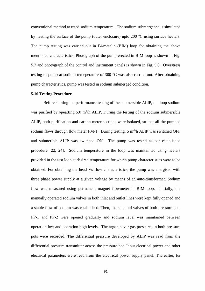
91
conventional method at rated sodium temperature. The sodium submergence is simulated
by heating the surface of the pump (outer enclosure) upto 200 οC using surface heaters.
The pump testing was carried out in Bi-metalic (BIM) loop for obtaining the above
mentioned characteristics. Photograph of the pump erected in BIM loop is shown in Fig.
5.7 and photograph of the control and instrument panels is shown in Fig. 5.8. Overstress
testing of pump at sodium temeperature of 300 οC was also carried out. After obtaining
pump characteristics, pump was tested in sodium submerged condition.
5.10 Testing Procedure
Before starting the performance testing of the submersible ALIP, the loop sodium
was purified by opearting 5.0 m3/h ALIP. During the testing of the sodium submersible
ALIP, both purification and carbon meter sections were isolated, so that all the pumped
sodium flows through flow meter FM-1. During testing, 5 m3/h ALIP was switched OFF
and submerible ALIP was switched ON. The pump was tested as per established
procedure [22, 24]. Sodium temperature in the loop was maintainted using heaters
provided in the test loop at desired temperature for which pump characteristics were to be
obtained. For obtaining the head Vs flow characteristics, the pump was energised with
three phase power supply at a given voltage by means of an auto-transformer. Sodium
flow was measured using permanent magnet flowmeter in BIM loop. Initially, the
manually operated sodium valves in both inlet and outlet lines were kept fully opened and
a stable flow of sodium was established. Then, the solenoid valves of both pressure pots
PP-1 and PP-2 were opened gradually and sodium level was maintained between
operation low and operation high levels. The argon cover gas pressures in both pressure
pots were recorded. The differential pressure developed by ALIP was read from the
differential pressure transmitter across the pressure pot. Input electrical power and other
electrical parameters were read from the electrical power supply panel. Thereafter, for
92
different sodium flow, the outlet sodium valve was throttled and the corresponding
pressure head readings were obtained for head Vs flow characteristics. This exercise was
repeated at various voltages in the range of 30 V to 120 V.
Experimental readings like pump head developed in kg/cm2, flow in m
3/h, applied
voltage in volts, input current in Amps, pump input electrical power in kW, winding
temperature and sodium temperature were recorded. Using experimental data of head
and flow, pump hydraulic characteristic of head Vs flow was drawn. Input power Vs flow
characteristics was obtained from the experimental readings. Efficiency of the pump was
calculated as follows:
Efficiency = Output power/Input power (5.1)
Output power = 27.25 x Flow x Head (5.2)
where Flow is in m3/h and Head is in kg/cm
2
Input power in kW is obtained from the experimental reading while the output
power in kW is calculated from the experimental data as per equation 5.2.
5.11 Test Results
Test results on pump characteristics and their comparision with theoretical
characterists are shown in Fig. 5.9 to Fig. 5.14.
Overstress test performed at 300 οC confirmed operation of the pump and its
sturdiness at higher temperature. The characteristic of the pump at 300 °C is shown in
Fig. 5.15.
After completion of above hydraulic performance testing, endurance testing for
1000 h at 200 °C, 2.0 m3/h and 4.0 kg/cm
2 of submersible ALIP was carried out. The
objective of the endurance testing was to confirm the satisfactory performance of the
Submersible ALIP over a long period of operation.

93
Cavitation test on ALIP was carried to evaluate the limit of inlet presure in pump
which may cause cavitation in the pump. Experiments revealed that the operation of
pump at inlet pressure of 0.3 kg/cm2 (abs) was cavitation free . The low inlet pressure
was obtained by throttling the inlet valve. The measurement of inlet pressure was done at
constant sodium level in inlet pressure pot using a vacuum pump.
Pressure vs flow characteristic was again obtained after 1000 h of endurance test
and the characteristic is shown in Fig. 5.16 ( 112 V- R curve).
The pump was tested in sodium submerged condition at sodium temperature
ranging from 250 oC to 500
oC for 2000 h. The drawing of facility where sodium
submerged test is carried out is shown in Fig. 5.17. Photograph of submerible ALIP
along with Integrated Cold Trap (ICT) during erection in the facility for sodium
submerged test is shown in Fig. 5.18.
5.12 Discussion on Test Results
Experimental hydraulic characteristic (Head Vs Flow) shown in Fig. 5.9 indicates
that pump is capable of developing the required head of 4.0 kg/cm2 at 2.0 m
3/h flow as
per design specification at reactor fuel handling temperature of 200 °C. The
experimental head Vs flow characteristic at 112 Volt is not smooth; this may be due to
manual error in measurement of head. Manual measurement of the head by pressure
balance technique is a tedious process and human errors are possible. The head Vs flow
characterisitic has trend of straight line which is attributed to higher resistance value of
MI cable winding since the copper conductor used in the MI cable winding is of smaller
size. Since the ALIP works on similar principle as of induction motor with exception of
field moving linearly instead of rotating, the head Vs flow characteristic of ALIP is
similar to torque Vs speed characterisitic of induction motor with high resistive winding.
The high resistive winding of ALIP makes the head Vs flow characteristic of ALIP as

94
drooping straight line as obtained in Fig. 5.9. The trend of experimental characteristic
(Head Vs Flow) is similar to theoretical characteric (Fig. 5.10). It is seen that
experimental head developed is marginally lower than the theoretical head and this may
be attributed to the manufacturing tolerances (slightly higher air gap). During the
experiment, flow instability and pump vibrations were not observed which verifies the
theretical calculation in Sec 3.7.
Experimental characteristic (input power Vs flow) at 200 °C is shown in Fig. 5.11.
The trend of experimental is similar to theoretical characteric (Fig. 5.12). The
experimental input power is slightly higher than the calculated input power. This may be
due to presence of core loss in experiment which is not considered in theoretical
calculation.
Experimental efficiency Vs flow at 200 °C is shown in Fig. 5.13. The trend of
experimental characteristic is similar to the theoretical characteristic (Fig. 5.14). The
efficiency of the developed submersible ALIP (around 1.2%) is found to be less than
conventional ALIP (around 5%) of same size. This is due to (i) use of MI cable, which
introduces higher resistance in winding hence higher copper loss, (ii) higher eddy current
loss in MI cable sheath and winding retainer plate. The higher losses results in lower
efficiency.
The overstress test at 300 °C proved robustness of the design and the concept
(Fig. 5.15). Experimental characteristic of the pressure head Vs flow obtained after 1000
h endurance test is shown in Fig. 5.16 ( 112 V- R curve) and the result obtained is nearly
same as that of experiments conducted before the endurance test. The repeat test after the
endurance test revealed that ther is no signinificant change in the hydraulic characteristic
(Head Vs Flow) and the pump continues to develop rated pressure even after considerable
duration (1000 h) of operation of the pump at rated operating temperature. Experiments
95
also revealed that the operation of pump at inlet pressure of 0.3 kg/cm2 (abs) was
cavitation free. Pump testing in sodium submerged condtion was also carried out for
2000h.
5.13 Summary
The developed sodium submersible ALIP was tested in a sodium loop that was
modified for carrying out the tests. Pressure measurement in sodium loop was carried out
by maintaining constant sodium levels in both inlet and outlet pressure pots using argon
pressure. The difference in argon pressure to maintain constant sodium levels in both the
sodium pots is a measure of the pressure developed by the pump. The experimental
characteristics obtained are compared with the theoretical predicted characteristics. The
experimental characteristics obtained validated the design and concept of annular linear
induction pump having winding made from mineral insulated stainless steel sheathed
cable. Tests confirmed the design of ALIP for use in high temperature submerged sodium
environment without need of any external cooling. The experimental head developed is
slightly less than the theoretical predicted head for given voltage. Similarly, experimental
power input is higher than the theroretical power input which results in lower
experimental efficiency than the theoretical efficiency. The reasons for above deviation
may be attributed to manufacturing tolerance and additional copper loss in pump.
Increase in small air gap will cause higher magnetizing current and hence, less pressure
head developed. In experiment no flow instability was observed.
In the theoretical model, core loss and duct hydraulic loss are not considered. In
the experiments, the input power consists of core as well as hydraulic losses resulting in
difference in theoretical and experimental values of various parameters. Eddy current in
stainless steel sheathed MI cable and winding retaining steel plate is accounted in the
theoretical design calculations with some assumptions and hence there is scope of
96
difference in theoretical and experimental values. The pressure measurements were
carried out manually and level fluctuation in pressure pot may have slight effect on
measurements. The overstress test at 300 oC proved robustness of the design and the
concept. The pump was operated for 1000 h as endurance test. The pump showed no sign
of cavitation during test at below atmospherics pressure in the inlet side. Also testing of
pump in fully sodium submerged condition at sodium temperature of 250 oC to 500
oC
was carried out for 2000 h operation. The successful performance testing of developed
ALIP in sodium has indicated the fulfillment of research objective.

97
Fig. 5.1 Flow sheet of BIM loop with submersible ALIP

98
Fig. 5.2 Piping for submersible ALIP testing

99
Fig. 5.3 Pressure pot with level probe details

100
Fig. 5.4 Argon cover gas header for pressure pots of ALIP testing facility

101
Fig. 5.5 Power supply wiring diagram for submersible ALIP
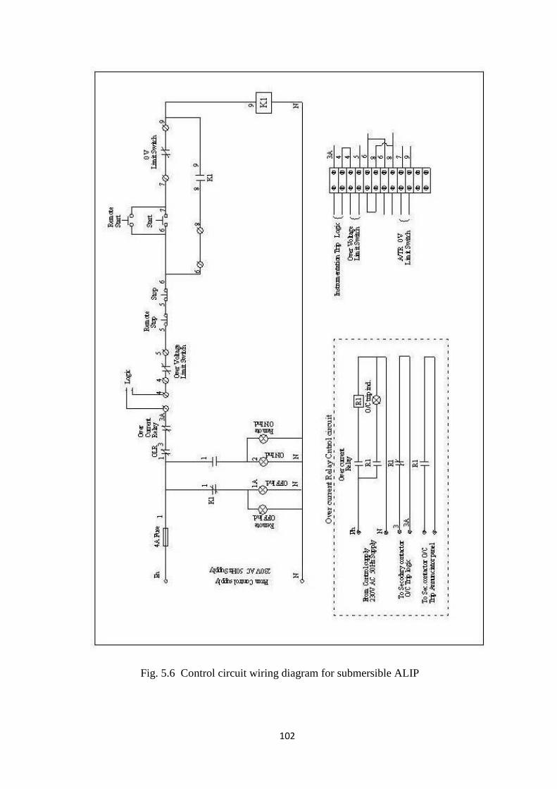
102
Fig. 5.6 Control circuit wiring diagram for submersible ALIP

103
Fig. 5.7 Photograph of pump erected in BIM loop
Fig. 5.8 Photograph of control and instrument panel and other electrical systems

104
ALIP Test Results
Fig. 5.9 Experimental Pressure Head Vs Flow characteristics at 200 ºC
Fig. 5.10 Comparison of experimental and theoretical
Pressure Head Vs Flow characteristics at 200 ºC

105
Fig. 5.11 Experimental Input Electrical Power Vs Flow at 200 ºC
Fig. 5.12 Comparison of Experimental and Theoretical
Input Electrical Power Vs Flow at 200 ºC

106
Fig. 5.13 Experimental Efficiency Vs Flow at 200 oC
Fig. 5.14 Comparison of Experimental and Theoretical Efficiency Vs Flow at 200 oC

107
Fig. 5.15 Experimental Pressure Vs Flow at 300 °C (Overstress Test)
Fig. 5.16 Pressure Vs Flow characteristics after endurance test of 1000 h

108
Fig. 5.17 Schematic of submersible ALIP in ICT

109
Fig. 5.18 Erection of submersible ALIP for testing in ICT
Submersible ALIP


110
CHAPTER 6
SUMMARY AND FUTURE PROSPECTS
6.1 Summary
Research work towards design and development of sodium submersible EM pump
for high temperature application was taken up for draining of sodium at 200 oC from the
main vessel of PFBR. Sodium draining is envisaged for inspection of sub-assembly
during shut down period of reactor operation and during reactor decommissioning.
Earlier to this research work, there was no device available which can be used for
draining of sodium from main vessel of PFBR. Other countries also had no dedicated
device for complete sodium draining, however, electromagnetic pump provided in
purification circuit was used for partial draining of sodium during decommissioning stage
[44]. Full draining of sodium using purification circuit electromagnetic pump is not
possible due to cavitation problem. After studying the constraints, development of device
was taken up with the following requirements:
1) Operating in sodium submerged condition
2) Withstanding sodium temperature of 200 oC
3) Operating without any external cooling
4) Getting inserted through inspection canal of 450.0 mm diameter and
5) Withstanding radiation field present in the reactor.
Various options were studied and based on the literature survey on
electromagnetic pumps, it was concluded that annular linear induction pump (ALIP) has
the potential to meet the above mentioned requirements. Considering this, research work
was carried out to develop an ALIP having stator winding made from mineral insulated
stainless steel sheathed cable. This cable had proved its capability for high temperature
operation and radiation withstanding capability in various devices such as mutual
111
inductance type level probe and DSRDM electromagnetic coil [14, 32]. Mathematical
modelling and derivation of various ALIP pump parameters were carried out using first
principles for better understanding. Design of 2.0 m3/h and 4.0 kg/cm
2 capacity ALIP was
carried out keeping sodium submerged pump hermetically sealed, compact, capable of
high temperature operation and radiation withstand capability criteria in mind. Finite
Element Method (FEM) analysis was carried out to predict theoretical performance of the
designed pump.
In this research work, design of ALIP was initiated with prevailing equivalent
circuit approach. This research work resulted in modification of prevailing equivalent
circuit to take into account the effect of eddy currents in stainless steel sheathed winding
and retainer plates. The modification incorporated in equivalent circuit is new knowledge
brought out in the field of ALIP. Design and development of a compact sodium
submersible ALIP having mineral insulated stainless steel sheathed winding capable of
working in sodium submerged condition at 200 oC without any need of external cooling
has demonstrated the fulfilment of research objective.
Manufacturing of ALIP was carried out in three stages. In the first stage,
development of 50 W three phase induction motor with 1.5 mm diameter mineral
insulated stainless steel sheathed cable was undertaken to prove the concept of mineral
insulated cable winding. In the second stage, manufacturing of 6.0 mm diameter mineral
insulated cable as per the design requirement of the ALIP was demonstrated. In the third
stage, sodium submersible ALIP was fabricated, prior to which, mock up trials for ALIP
winding with mineral insulated stainless steel cable were carried out. Stainless steel,
mineral insulation and copper conductor (for carrying current) were the materials used in
the ALIP. All these materials have proven record of withstanding high temperature and

112
radiation field. Hence, the designed ALIP can withstand the designated high temperature
as well as radiation field making it well suited for reactor operation.
In submersible ALIP winding, copper conductor occupies less area in the stator
slot because high percentage of area is being occupied by MgO insulation as well as
stainless steel sheath. Less conductor area results in higher current density. The mineral
insulated stainless steel sheathed cable can withstand high current density upto 20 A/mm2
compared to 2 - 5 A/mm2 in conventional EM pump. However this results in higher
copper loss in the winding. The eddy current loss due to stainless steel sheathed winding,
retainer plate and higher copper loss in winding has reduced the efficiency of the
designed ALIP considerably low (around 1.5 %) compared to conventional ALIP of same
capacity which may have efficiency around 5.0 %. The designed ALIP is capable of
developing required pumping pressure of 4.0 kg/cm2
at 2.0 m3/h flow. The designed
pump has 400.0 mm diameter lateral dimension which can be easily inserted through
available inspection canal of PFBR.
The concept of ALIP, having stator winding made from mineral insulated
stainless steel sheath cable which can withstand temperature up to 550 oC is new and it is
not reported in open literature. ALIP design was carried out as per lump parameter
model and the design was analysed using a commercial FEM software.
The manufactured ALIP was tested in sodium loop under similar condition to
reactor (except radiation). The sodium testing at 200 οC without any external cooling of
ALIP has validated the design and the new concept. The stator winding withstood
temperature of 550 οC during endurance testing of 1000 h. During testing, no flow
instability was observed. Pump characteristics such as Pressure Head V/s Flow, Input
Power Vs Flow, Efficiency Vs Flow at 200 οC were obtained from experiments.
Overstress test at 300 οC and endurance testing for 1000 h proves robustness of the

113
design and the concept. The pump has operated without cavitation at low inlet pressure
at rated flow. The pump has been also operated in sodium submerged condition for 2000
h at temperature varying from 250 oC to 500
oC which is much above the rated operating
condition.
Application of this research work is not limited to above mentioned application
but it can be used in many other applications in sodium cooled fast reactors and sodium
experimental facilities such as integrated cold trap system and in-core material testing.
6.2 Future Research Prospects
The completed research work has opened new avenues of research. Research
work can be initiated for development of fire survival induction motor based on stator
winding made from mineral insulated stainless steel sheath cable. The fire survival
induction motor can be used for pumping fire extinguisher even they themselves are
engulfed in fire.
The present bearing used in the motor can not work at high temperature (>150 °C)
because of evaporation of lubricant. This opens an avenue for development of high
temperature bearings made of ceramic, which does not require the use of any lubricant.
Ceramcis are also suggested because they can withstand high temperature due to lower
coefficient of thermal expansion compared to metal.
In the present design, considerable slot space is used by non-current carrying
materials like steel and MgO, resulting in higher resistance of winding due to lower area
available for copper, leading to higher loss and lower efficincy of ALIP. In future,
research work may be extended to develop winding insulation using Mica and other
ceramic powder with suitable adhesive for high temperature operation in radiation field.
This research will lead to better slot utilization by copper winding, resulting in better
efficiency of ALIP.
114
In future, research work can be initiated for precise calculation of eddy current
loss in mineral insulated stainless steel sheath cable of ALIP and its effect on ALIP
performance. Further research in the domain of use of variable frequency power supply
for improving the efficiency of ALIP may be carried out. FEM modelling may be
efficient tool for carrying out further research towards analysis of pump magnetic field
and performance evaluation. In the modelling, it is essential to take account of stainless
steel sheath over the copper core and azimuthal irregularity of positioning of stator core
for accurate theoretical performance evaluation. This can also be taken up as future
research work. Research can be extended towards optimization of pump performance as
well as in the field of understanding pump instability criteria.
*****


115
APPENDIX-A
CALCULATIONS FOR 2.0 m3/h, 4.0 kg/cm
2 SUBMERSIBLE ANNULAR LINEAR
INDUCTION PUMP (ALIP)
Various parameters of the pump were designed as per the mathematical model developed
in chapter 2 and as per electromagnetic hand book [12]. In design, some of the input
parameters are chosen as per requirement and based on earlier experience and other are
computed as per the developed model.
Flow = 2.0 m3/hr
Eb= Input Voltage = 150 V
TCu= Temperature of the Copper/ MI Winding = 600°C.
T1=Specified Liquid Metal Temperature = 600° C
D1=Annular passage = 2.09 mm
D2= Thickness of the outer duct wall = 3 mm
D3 = Clearance between Outer duct wall and the stator bore surface = 2 mm
D4 = Thickness of SS jacket surrounding the core = 1.65 mm
D9 = Diameter of centre core = 45 mm
D12= Clearance between bottom of coil side and bottom of slot = 0 mm
D13 = Depth of coil side = 11 layers of Dia 6.05 mm MI Cable = 11 x 7 = 77 mm
(Taking coil expansion during winding into account since winding may not remain
very tight during winding process.)
D10 = Width of Stator Tooth = 10 mm
D11 = Width of Stator Slot = 16 mm
N1 = Number of Poles = 4
N2 = Number of Phases = 3
N3 = Number of slots per pole per phase = 2
N7= Number of turns per coil = 22
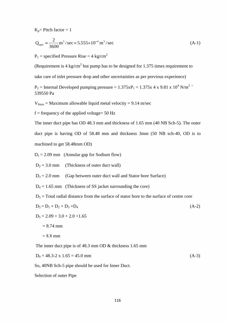
116
Kp= Pitch factor = 1
sec/m10555.5sec/m3600
2Q 343
spec (A-1)
P1 = specified Pressure Rise = 4 kg/cm2
(Requirement is 4 kg/cm2 but pump has to be designed for 1.375 times requirement to
take care of inlet pressure drop and other uncertainties as per previous experience)
P2 = Internal Developed pumping pressure = 1.375xP1 = 1.375x 4 x 9.81 x 104 N/m
2 =
539550 Pa
Vfmax = Maximum allowable liquid metal velocity = 9.14 m/sec
f = frequency of the applied voltage= 50 Hz
The inner duct pipe has OD 48.3 mm and thickness of 1.65 mm (40 NB Sch-5). The outer
duct pipe is having OD of 58.48 mm and thickness 3mm (50 NB sch-40, OD is to
machined to get 58.48mm OD)
D1 = 2.09 mm (Annular gap for Sodium flow)
D2 = 3.0 mm (Thickness of outer duct wall)
D3 = 2.0 mm (Gap between outer duct wall and Stator bore Surface)
D4 = 1.65 mm (Thickness of SS jacket surrounding the core)
D5 = Total radial distance from the surface of stator bore to the surface of centre core
D5 = D1 + D2 + D3 +D4 (A-2)
D5 = 2.09 + 3.0 + 2.0 +1.65
= 8.74 mm
≈ 8.8 mm
The inner duct pipe is of 48.3 mm OD & thickness 1.65 mm
D9 = 48.3-2 x 1.65 = 45.0 mm (A-3)
So, 40NB Sch-5 pipe should be used for Inner Duct.
Selection of outer Pipe
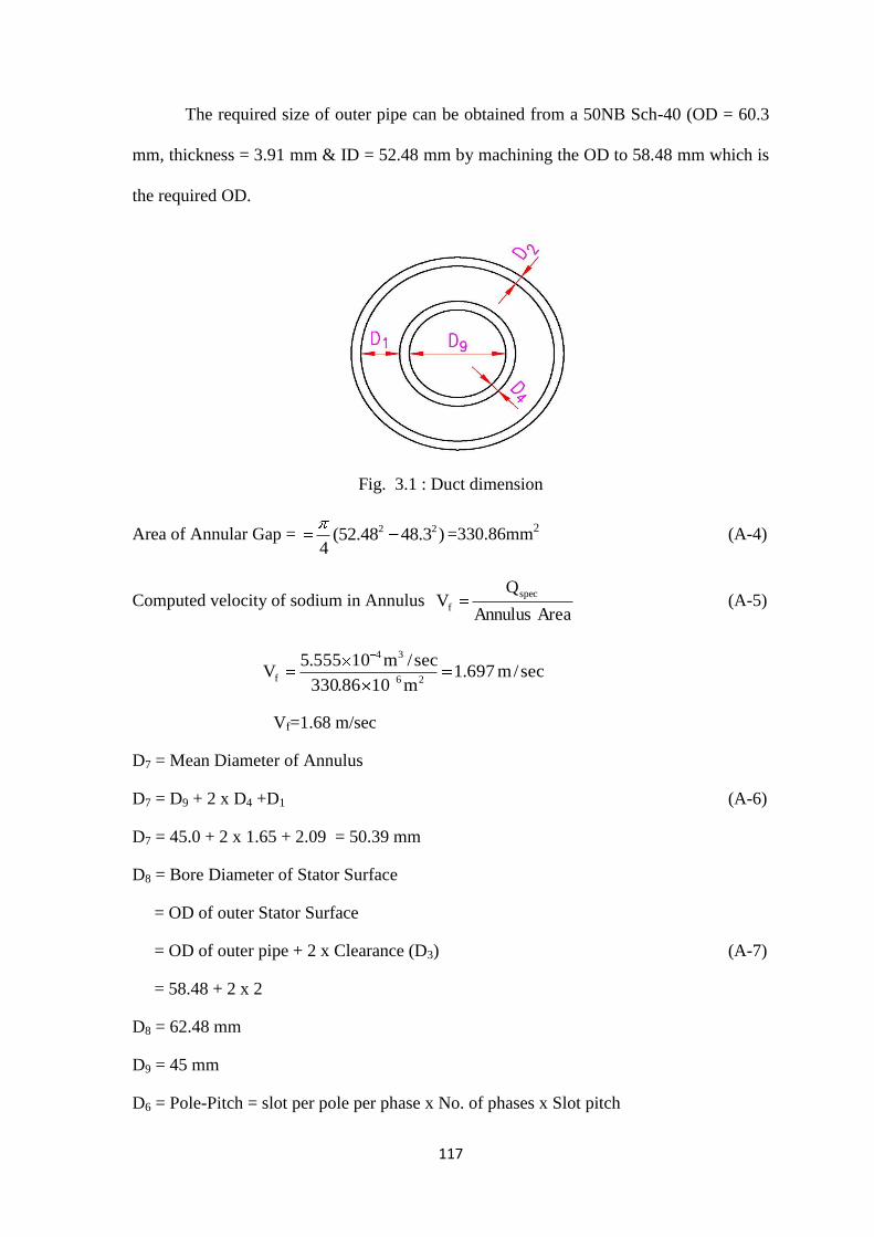
117
The required size of outer pipe can be obtained from a 50NB Sch-40 (OD = 60.3
mm, thickness = 3.91 mm & ID = 52.48 mm by machining the OD to 58.48 mm which is
the required OD.
Fig. 3.1 : Duct dimension
Area of Annular Gap = 2 2(52.48 48.3 )4
=330.86mm2
(A-4)
Computed velocity of sodium in Annulus AreaAnnulus
QV
spec
f (A-5)
sec/m697.1m1086.330
sec/m10555.5V
26
34
f
Vf=1.68 m/sec
D7 = Mean Diameter of Annulus
D7 = D9 + 2 x D4 +D1 (A-6)
D7 = 45.0 + 2 x 1.65 + 2.09 = 50.39 mm
D8 = Bore Diameter of Stator Surface
= OD of outer Stator Surface
= OD of outer pipe + 2 x Clearance (D3) (A-7)
= 58.48 + 2 x 2
D8 = 62.48 mm
D9 = 45 mm
D6 = Pole-Pitch = slot per pole per phase x No. of phases x Slot pitch

118
D6 = N3 N2 (D10+D11) (A-8)
D6 = 2 x 3 x (10 + 16)
D6 = 156 mm
D12 = Clearance between bottom of coil side and bottom of slot = 0 mm
D13 = Depth of coil side = 11x 7 =77 mm
D14 = Depth of slot = 90 mm
(Depth of the slot has been provided somewhat extra to take care of the compressibility
of MI cable in the slot)
D15 = Mean length of coil turn = π x Mean diameter of coil (A-9)
= π x (Bore dia + Slot Depth)
= π x (62.48 + 90 )
D15 = 479.03 mm
N1 = No. of Poles produced by stator = 4
N2 = No. of Phases = 3
N3 = No. of slots per pole per phase = 2
N4 = No. of slots in the stator = N1 x N2 x N3 = 24
N5 = No. of teeth in the stator = N4 + 1 = 25
N6 = No. of Stator coils = N4 = No. of Slots = 24
N7 = No. of Turns per coil = 22
D17 = Depth of back iron (yoke) = 29 mm
D18 = Overall Diameter of pump
D18 = D8 + 2 x D14 + 2 x D17 (A-10)
D18 = 62.48 + 2 x 90 + 2 x 29 = 300.48mm
D19 = Pump Length = N4 (D10 + D11) + D10 (A-11)
D19 = 24 x (10 + 18) +10 = 634mm
Nsc = Effective Number of turns in series per phase
turns1763
2422
N
NN
2
67 (A-12)
119
Kp = pitch factor = 1
Kd = Winding Distribution Factor
9659.015sin2
30sin
232
180sin2
32
180sin
NN2sinN
N2sin
K
32
3
2
d (A-13)
N8 = Carter Co-efficient
2
5
11
11
5
5
111
2D
D1ln
D
D
D2
Dtan
2 (A-14)
2
1
28.8
161ln
16
8.8
8.82
16tan
2
N8 = 0.26024
N9 = Multiplier for D5 to account for apparent increase in D5 due to slot
)26024.01(1610
1610
)N1(DD
DD
81110
1110 (A-15)
N9 = 1.1906
Qsyn = 2πfD7D1D6 (A-16)
= 2π x 50 x 50.39 x 2.09 x 156 x 10-9
m3/sec
Qsyn = 5.1612 x 10⁻³
m3/sec
Qspec = flow/sec = 2.0/3600 = 5.55555 x 10⁻⁴
m3/sec
Sodium velocity in Annulus = 1.68 m/sec
Slip 3
43
syn
specsyn
101612.5
105555.5101612.5
Q
QQ (A-17)
Slip = 0.8923
Resistivity of Copper at 600 °C
ρCu = [148.54 + 0.2748(1.8 x TCu + 32) + 0.000058 (1.8TCu + 32)2] x 10
-10 (A-18)
ρCu = [148.54 + 0.2748(1.8 x 600 + 32) + 0.000058 (1.8x 600 + 32)2] x 10
-10
ρCu = [148.54 +311.1376 +71.7195] x 10-10

120
ρCu = 531.397 x 10⁻¹⁰
Ω m
Resistivity of Stainless Steel at 600 °C
ρSS = [6.96 x 10⁻⁷
+ 8.78 x 10⁻¹⁰
x TSS -3.01 x 10⁻¹³
TSS2] (A-19)
Temperature of Stainless Steel TSS = Temperature of Liquid Metal = T1= 600 °C
ρSS = [6.96 x 10⁻⁷
+ 8.78 x 10-10
x 600 -3.01 x 10⁻¹³
6002]
ρSS = [6.96 x 10⁻⁷
+5.268 x 10⁻⁷
-1.0836 x 10⁻⁷
]
ρSS =1.11444 x 10⁻⁶
Ω m
Resistivity of Sodium at 600°C
ρNa = 8.14 x 10⁻⁸
+ 2.27 x 10⁻¹⁰
x T1 + 2.99 x 10⁻¹³
T12
(A-20)
ρNa = 8.14 x 10⁻⁸
+ 2.27 x 10-10
x 600 + 2.99 x 10-13
x 6002
ρNa = 8.14 x 10⁻⁸
+1.362 x 10⁻⁷
+ 1.0764 x 10⁻⁷
ρNa = 3.2524 x 10⁻⁷
Ω m
R1, Resistance of Stator Copper Winding
Length of Cu-winding = Length of mean turn x Total no. of turns per phase
= D15 x Nsc (A-21)
= 479.03 x 176 = 84.309 metres
Taking into account the compressibility of MI Cable and the extra length required for
making the terminations, the length of the MI winding can be taken as 130 metres.
Therefore, Resistance of Stator MI winding per phase
conductorCopper of Area
dingCopper win ofLength C 600at Copper ofy resistivit (A-22)
For the chosen MI Cable, the conductor diameter is 2.6mm
Therefore, area of copper conductor = (π/4) x (2.6 x 10-3
)2 = 5.26837 x 10
-6 m
2
Resistance R1 6
10
1026837.5
10397.531130= 1.3112 Ω per phase
X1 – Stator winding Leakage Reactance

121
X1 =2
DD
6
DD
D
NNNf1096.4 128138
11
2
731
5
(A-23)
2
01048.62
6
10771048.62
1016
2224501096.4 333
3
25
X1 = 0.4812 Ω per phase
Xm – Magnetising Reactance
Xm=591
2
dpsc762db
6
DNN
)KKN(DDNfff105.2 (A-24)
fd = Flux distribution factor – the ratio of the average value of flux wave to the maximum
value of the flux wave. For sinusoidal flux distribution, fd = 0.637 (or, (2/π)).
fb = Form factor of flux wave; represents the ration of the peak value to the rms value. For
a sinusoidal flux wave, fb = 1.11
3
2336
m108.81906.14
)9659.01176(1039.50101563637.011.150105.2X
Xm = 1.4502 Ω per phase
Rw – Equivalent Resistance of the outer annulus Wall
Rw )DNDN(D
)KKN()DDD(N
1051142
2
dpsc7212SS (A-25)
33
236
10)10251624(103
)9659.01176(10)39.500.309.2(31011444.1
Rw = 8.8538 Ω per phase
Rj- Equivalent Resistance of jacket around Centre Core
Rj )DNDN(D
)KKN)(DD(N
1051144
2
dpsc942SS (A-26)
33
236
10)10251624(1065.1
)9659.01176(10)4565.1(3101144.1
Rj = 13.5357 Ω per phase
Rc- Equivalent Resistance of Rw and Rj in parallel
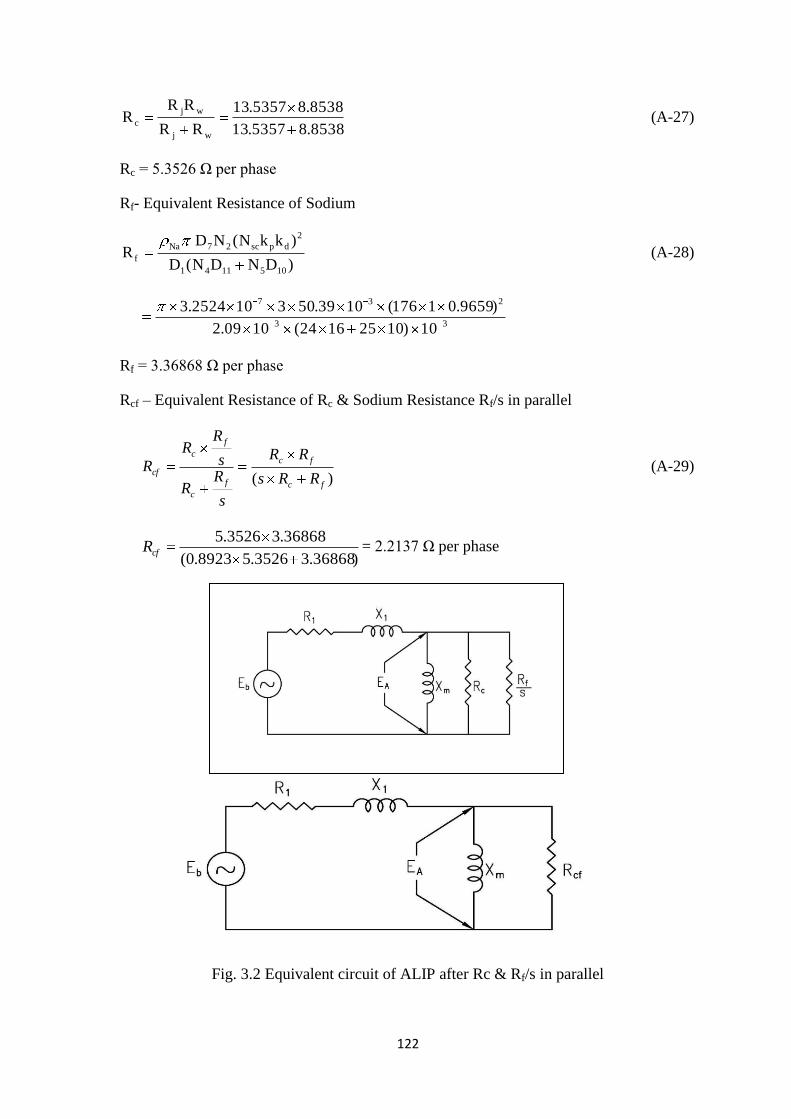
122
8538.85357.13
8538.85357.13
RR
RRR
wj
wj
c (A-27)
Rc = 5.3526 Ω per phase
Rf- Equivalent Resistance of Sodium
)DNDN(D
)kkN(NDR
1051141
2
dpsc27Na
f (A-28)
33
237
10)10251624(1009.2
)9659.01176(1039.503102524.3
Rf = 3.36868 Ω per phase
Rcf – Equivalent Resistance of Rc & Sodium Resistance Rf/s in parallel
)( fc
fc
f
c
f
c
cfRRs
RR
s
RR
s
RR
R (A-29)
)36868.33526.58923.0(
36868.33526.5cfR = 2.2137 Ω per phase
Fig. 3.2 Equivalent circuit of ALIP after Rc & Rf/s in parallel
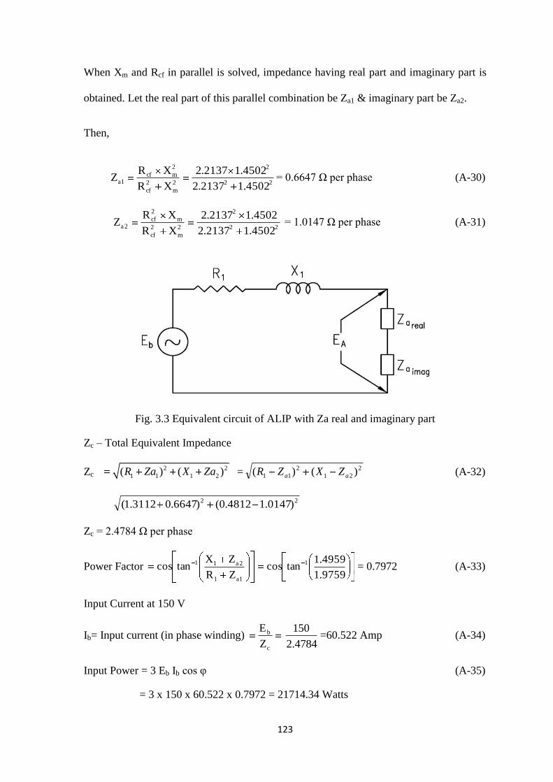
123
When Xm and Rcf in parallel is solved, impedance having real part and imaginary part is
obtained. Let the real part of this parallel combination be Za1 & imaginary part be Za2.
Then,
22
2
2
m
2
cf
2
mcf1a
4502.12137.2
4502.12137.2
XR
XRZ = 0.6647 Ω per phase (A-30)
22
2
2
m
2
cf
m
2
cf2a
4502.12137.2
4502.12137.2
XR
XRZ = 1.0147 Ω per phase (A-31)
Fig. 3.3 Equivalent circuit of ALIP with Za real and imaginary part
Zc – Total Equivalent Impedance
Zc 2 2
1 1 1 2( ) ( )R Za X Za =2
21
2
11 )()( aa ZXZR (A-32)
22 )0147.14812.0()6647.03112.1(
Zc = 2.4784 Ω per phase
Power Factor 9759.1
4959.1tancos
ZR
ZXtancos 1
1a1
2a11= 0.7972 (A-33)
Input Current at 150 V
Ib= Input current (in phase winding) c
b
Z
E 150
2.4784=60.522 Amp (A-34)
Input Power = 3 Eb Ib cos φ (A-35)
= 3 x 150 x 60.522 x 0.7972 = 21714.34 Watts
124
Input Power = 21.71 kW
EA – Voltage induced in Xm
EA bb IjXRE )(0 11 (A-36)
= 69.146 + j 24.681
EA = 73.419 Volts
Phase angle of EA with respect to Eb = tan-1 24.681
69.146 = 19.64° (A-37)
Po – Pressure rise across the pump
2
spec1
synf
2
A2
1
1o Qk
QR
sEN
1N
1NP (A-38)
Neglecting Hydraulic losses
synf
2
A2
1
1o
QR
sEN
1N
1NP (A-39)
3
2
101612.536868.3
419.738923.03
14
14
Po = 497993.4345 Pascal
Po = 4
497993.4345
9.81x 10 = 5.076 kg/cm
2 (A-40)
Taking conservative approach, therefore, the head developed by pump at rated flow and
at 150 V = 4 kg/cm2. This is meeting the requirement.
Output of Pump = Po x Qspec (A-41)
=497993.4345 x 5.55 x 10-4
= 276.66 Watts
Efficiency of Pump Pump output (mech) Power
Pump Input (Electrical) Powerx 100 % (A-42)
276.66
21714.34x 100
Efficiency of Pump = 1.274 %

125
Total Flux φt scdpb
A1
Nkkff2
EN (A-43)
1769659.0111.1502
419.734
φt = 0.015663394 wb
Bj - Jacket Flux Density
232
91
tj
)1045(4
015663394.0637.0
DN
637.0B (A-44)
Bj = 1.2239 Wb/m2
Bt – Tooth Flux Density
d1085
tt
f9.0DDNB (A-45)
637.09.010101048.6225
015663394.0B
33t
Bt = 0.5532 Wb/m2
Wall Losses
Loss in Wall 3526.5
419.733
R
ENL
2
c
2
A2w =3021.18 Watts (A-46)
Lw = 3021.18 kW
Losses in Sodium,3686.3
)419.738923.0(3 222
2
f
Asod
R
EsNL (A-47)
Lsod = 3822.65 Watts
Cu-loss in Stator (LCu)
LCu = N2I2R1, LCu = 3 x 60.90
2 x 1.3112 (A-48)
LCu = 14409.402 Watts. LCu =14.409 kW
Im Magnetising Current
Amp62.504502.1
419.73
X
EI
m
Am (A-49)


126
APPENDIX – B
Material specification and inspections followed during manufacturing
B.1 Specification of cold rolled grain oriented steel (CRGO – 41) for lamination
a) Applicable Standard : IS 3024 (Wherever applicable)
b) Nominal Thickness : 0.28mm
c) Insulation : Both surface of lamination are insulated with inorganic insulation coating
capable of withstanding stress relief annealing.
d) Annealing : Punched and sheared laminations were annealed at 1033 K – 1063K by
Conveyor Annealing process and IR was checked at regular interval to ensure no
appreciable drop in IR as per standard.
e) Lamination : i) Grain orientation for stator is along the tooth length. The laminations
were free from burrs and irregularities to enable proper stacking. Minimum oil was
used during punching and all traces of oil were removed before taking up annealing.
ii) For centre core, direction of grain orientation was along the length of the
lamination. No oil was used while shearing.
f) Guaranteed maximum iron loss: 0.9 W/kg at 1.5T and 50 Hz. In the direction of grain
orientation.
g) Inspection of CRGO 41:
i) Chemical analysis of CRGO-41 material
(Minimum content of Silicon shall be 3%)
ii) Test certificate from a mutually accepted agency for maximum iron loss value
was checked to confirm that the material corresponds to CRGO-41
iii) Dimensions of the punched and sheared laminations, insulation resistance of
inorganic coating by 50V megger, watt loss and grain orientation were inspected.
iv) Stress relief annealing was carried out and watt loss and IR were checked again.

127
B.2 ALIP Assembly
First coils were wound on the outer duct assembly as shown in the drawings and
checks mentioned were carried out. The inner duct assembly was manufactured and
inserted inside the outer duct assembly and tack welded. Both the support flanges were
inserted from both the ends of duct assembly. All the stator core assembly were fixed
between support flange one by one. Support flanges and outer duct were welded. MI
cable leads were brought out suitably from the top/right flange through cylindrical pipe of
suitable length. Then the outer cylindrical enclosure was inserted over two support
flanges and welded to both the support flanges. Suitable sealing arrangement for the MI
cable leads to come out from the ALIP was made.
B.3 Inspection and Tests
B.3.1 Dimensional inspection
Dimensional check for the individual components and the completed pump were
carried out as per the approved procedures.
B.3.2 Non-destructive examinations
B.3.2.1 Liquid penetrant examination of weld edge preparation, root pass & final pass for
all butt welds and root pass & final pass for all fillet welds was carried out as per
specification. No indication was acceptance criteria for weld edge preparation.
B.3.2.2 Radiographic examination was carried out for 100% weld length on all the finish
butt welds as per specification. The acceptance criteria for radiographic
examination was as per class-1. In case of full penetration weld joints where
radiographic examination cannot be performed satisfactorily, ultrasonic
examination for 100% weld length as per was carried out.
B.3.2.3 Leak detection of completed / finished component was done under vacuum with
helium. Wherever weld joints were not accessible for repair after global leak

128
testing, that individual component was helium leak tested stage wise before final
assembly. Whenever leak detection under vacuum was not feasible, leak detection
using helium under pressure was done.
B.3.3 Inspection on assembly of stainless steel sodium duct
a) Dimension check : On all individual machined/fabricated parts and assemblies.
b) Measurement of weight of centre core assembly and ring flux test on centre core
assembly was done before welding of centre core.
c) Welding inspection:
i) Dimensional check on edge preparation
ii) Liquid penetration (LP) check on edge preparation
iii) LP check on each weld pass.
d) Radiography: All the butt weld joints of stainless steel are 100%
radiographed after final pass.
e) Pneumatic test and Helium leak test:
i) Pneumatic and Helium test on outer duct assembly before fabrication of
winding on duct:
After completing the duct assembly (outer duct with fins welded), pneumatic test
(on duct assembly) was carried out with 2.0 MPa (g) and the test procedure and
acceptance criteria was as per ASME Section III sub-section NB. Pneumatic test
was followed by Helium leak test by evacuating the outer duct.
ii) Pneumatic and Helium test on complete duct assembly with fabricated winding
on duct:
After completing the duct assembly (outer and inner duct welded), pneumatic test
(on duct assembly) was carried out with 2.0 MPa (g) and the test procedure and
acceptance criteria was as per ASME Section III sub-section NB. Pneumatic test
129
was followed by Helium leak test by evacuating the duct.
iii) Pneumatic & Helium leak test on inner duct assembly:
After completion of lamination filling in the inner core and after welding the
diffuser cone, the entire inner duct assembly underwent pneumatic pressure test
(external) as per ASME section III, sub-section NB. The test pressure was 2.0
MPa (g) external to the inner duct assembly. A separate container of carbon
steel was made to keep the inner duct assembly for pressure testing.
Helium leak test for inner duct under vacuum was carried out after the
completion of pneumatic test. A hole drilled for helium leak test was plugged
and welded after the test and DP check was carried out as per specification.
iv) Pneumatic & Helium leak test on Duct assembly:
After completing the duct assembly (outer duct with fins welded and central core
assembled), pneumatic test (on duct assembly) was carried out with 2.0 MPa (g)
and test procedure and acceptance criteria were as per ASME Section III sub-
section NB. Pneumatic test was followed by Helium leak test by evacuating the
outer duct and it was carried out as per specification.
B.3.4 Inspection on coil/winding during manufacture
a) Winding inspection during coil fabrication
i. Proper laying of coil and checking of proper direction of coil
ii. Insulation resistance between coil conductor and the ground. IR value was
greater than 100000 Mega ohms ( measurement as per IS 7816).
iii HV test at 2.5 kV r.m.s for one minute between Phase to earth and between
phase to phase. It withstood the HV test.
iv) Vibrations and current balance checked at 60 to 80 V in the final
assembly for short time not exceeding 3 minutes.


130
REFERENCES
1 Anil Kakodkar, ―Evolution of nuclear reactor containments in India: Addressing the
present day challenges‖, Nuclear Engineering and Design 269 (2014) 3–22.
2 Chetal, S.C., Balasubramaniyan, V., Chellapandi, P., Mohanakrishnan, P.,
Puthiyavinayagam, P., Pillai, C.P., Raghupathy, S., Shanmugham, T.K., Pillai, C.S.,
The design of the prototype fast breeder reactor. Nuclear Engineering and Design 236,
852–860, 2006.
3 Kazumi Aoto, Philippe Dufour, Yang Hongyi, Jean Paul Glatz, Yeong-il Kim, Yury
Ashurko, Robert Hill, Nariaki Uto, ―A summary of sodium-cooled fast reactor
development‖,Progress in Nuclear Energy, 2014,
http://dx.doi.org/10.1016/j.pnucene.2014.05.008
4 R.K. Sinha, A. Kakodkar, ―Design and development of the AHWR—the Indian thorium
fuelled innovative nuclear reactor‖, Nuclear Engineering and Design 236 (2006) 683–
700.
5 Jagdish Tyagi, Mithilesh Kumar, H.G. Lele, P. Munshi, ―Thermal hydraulic analysis of
the AHWR—The Indian thorium fuelled innovative nuclear reactor‖, Nuclear
Engineering and Design 262 (2013) 21–28.
6 G. Srinivasan , K.V. Suresh Kumar, B. Rajendran, P.V. Ramalingam, ―The Fast Breeder
Test Reactor—Design and operating experiences‖, Nuclear Engineering and Design
236 (2006) 796–811.
7 J.I. Sylvia, M.R. Jeyan, M. Anbucheliyan, C. Asokane, V. Rajan Babu, B.Babu, K.K.
Rajan, K. Velusamy, T. Jayakumar, ―Ultrasonic imaging of projected components of
PFBR‖, Nuclear Engineering and Design 258 (2013) 266–274.
8 B K Nashine,S K Dash,K Gurumurthy,U Kale, V D Sharma, R Prabhakar,M Rajan &
G.Vaidyanathan, ―Performance testing of indigenously developed DC conduction pump
for sodium cooled fast reactor‖, Indian Journal of Engineering & Materials Sciences
Vol. 14, June 2007, pp. 209-214
9 Aizawa Kosuke, Chikazawa Yoshitaka, Kotake Shoji, Ara Kuniaki, Aizawa Rie and Ota
Hiroyuki, Electromagnetic Pumps for main cooling Systems of Commercialized sodium-
cooled fast reactor, Journal of Nuclear Science and Technology, Vol. 48, No.3, p. 344-
352, 2011.
131
10 Andreev, A. M. , Danilin, V. G. , Karasev B. G. , Kirillov, I.R. , Choice of constructional
schemes of electromagnetic pumps for atomic energy stations with fast reactors,
Magnitnaya Gidrodinamika, No. 1, pp- 101-105, January-March, 1982.
11 Anisimov, A. M. , Vitkovsky, I.V., Golovanov, M. M. , Kirillov, I. R., Krizhanovsky, S.
A. , Preslitsky, G. V. , Chaika, P. Yu., Zotov, V. G. , and Sedakov, V. Yu.,
Electromagnetic Pumps for BN-800, Atomic Energy, Vol. 112, No. 6, October 2012.
12 Baker, R.S. and Tessier, M.J., "Handbook of Electromagnetic Pump Technology‖,
Elsevier Publications, 1987.
13 Blake, L.R. , Conduction and induction pumps for liquid metals, Proceedings of the IEE
- Part A: Power Engineering, Volume 104, Issue 13, p. 49 – 67, February 1957.
14 J.I. Sylvia , P. Vijayamohana Rao, B. Babu, K. Madhusoodanan, ―Development of
mutual inductance type sodium level detectors for PFBR‖, Nuclear Engineering and
Design 262 (2013) 219–227.
15 Kirillov, I.R., Electromagnetic Pumps for nuclear power, Magnitnaya Gidrodinamika,
No.3, pp. 87-97, July-September, 1982.
16 Hee Reyoung Kim, Yong Bum Lee, A design and characteristic experiment of the small
annular linear induction electromagnetic pump, Annals of Nuclear Energy 38 , 1046-
1052, 2011.
17 Say, M.G., The Performance and Design of Alternating Current Machines, Third
Edition, CBS Publishers, 2000
18 Kirillov, I.R., Obukhov, D.M., ―Two Dimensional model for analysis of cylindrical
linear induction pump characteristics: model description and numerical analysis‖,,
Energy Conversion and Management 44 (2003).
19 Sharma Prashant, Sivakumar L.S. Rajendra Prasad, R., Saxena D.K., Suresh Kumar
V.A., Nashine B. K., Noushad I.B., Rajan, K.K., Kalyanasundaram, P.,―Design,
Development and Testing of A Large Capacity Annular Linear Induction Pump‖,
Journal Of Energy Procedia, Vol.7, pp.622-629, 2011.
20 Watt, D. A. ―The design of electromagnetic Pumps for Liquid metals‖, The Institution of
Electrical Engineers, Paper No. 2763 U, Dec. 1958.
21 Werkoff, F., ―Finite-Length Effects and Stability of Electromagnetic Pumps‖,
Experimental Thermal and Fluid Science 1991.
22 Masayoshi Nakazaki, et al, Performance evaluation of the Sodium Immersed Self
Cooled Electromagnetic Pump, Proceeding of ICONE 5, May 26-30,1997, Nice, France
132
23 H.V. Khang, A. Arkkio, ―Eddy-Current Loss Modelling for Form- Wound Induction
Motor Using Circuit Model‖, IEEE Transaction on Magnetics, Vol.48, No 2, Feb 2012.
24 Hee Reyoung KIM, Sang Hee HONG, Design and Experimental Characterization of an
EM Pump, Journal of Korean Physical Society, Vol 35, No 4, Oct 1999, pp 309-314
25 M Nakazaki, et al Development of Sodium Immersed Self Cooled Electromagnetic
Pump, FR91, Tokyo 1991, P2.16-1 to P2. 16-7
26 Hiroyuki OTA, et al, Development of 160 m3/h Large Capacity Sodium Immersed Self
Cooled Electromagnetic Pump, Journal of Nuclear Science and Technology, Vol 41,
No4, p 511-523, April 2004
27 W. Kwant, A. W. Fanning, Y. Dayal, H. Ikeda, J. Taguchi, M. Nakazaki, J. M. Boggio,
In –Sodium Testing and Performance of A 43.5 m3/min Electromagnetic Pump for LMR
Application, Proceeding of ICONE 5, May 26-30,1997, Nice, France
28 Hideo Araseki, Igor Kirillov, Anatoly Ogorondnikov, Gennady Preslitsky, Pulsations of
Parameters in Annular Linear Electromagnetic Pumps for Fast Breeder Reactors, 11th
International Conference On Nuclear Engineering, Tokyo, Japan, April 20-23, 2003
29 A.W.Fanning, W.Kwant, M.Patel, Double Stator Electromagnetic Pump for the ALMR
Primary System‖, International Conference on design and Safety of Advance NPPS,
Tokyo October 92.
30 P. Del Vecchio, A. Geri and G.M.Vecca,Superconducting Magnet for Electromagnetic
D.C.Pumps‖, IEEE Trans. on Magnetics, VOL. MAG-21, NO.2, MARCH 1985.
31 Vitkovskii, I.V., Kirillov, I.R. , Chaika. P. Yu., Kryuchkov, E. A. , Poplavskii, V. M.,
Nosov, Yu. V., and Oshkanov, N. N., Performance-based reliability assessment of
electromagnetic pumps, Atomic Energy, vol. 102, 2007.
32 H. Bock and M. Suleiman, Investigations of mineral insulated cables exposed to high
temperature and intense gamma radiation, Nuclear Instruments and Methods- 148-
(1978) 43-50; North-Holland Publishing Co.
33 Prashant Sharma, R.Vijayashree, B.K. Nashine, S.K. Dash, G. Vijayakumar, K.A.Gopal,
S. Sosamma, C. Babu Rao, K.K. Rajan, Sensor development for position detection of
diverse safety rod of fast reactor, Annals of Nuclear Energy, Volume 46, August 2012,
Pages 189–196.
34 D. C. Meeker, Finite Element Method, Magnetics, Version 4.2.
35 J. Pedra, I. Candela, A.Barrera, Saturation model for squirrel-cage induction motors,
Electric Power Systems Research 79 (2009) 1054–1061.
133
36 B. Laporte, G. Vinsard, J.C. Mercier, A computation method for induction motors
in steady-state, Mathematics and Computers in Simulation 38 (1995) 369-376.
37 Y.S. Chen, Y.D. Cheng, J.J. Liao, C.C. Chiou, Development of a finite element solution
module for the analysis of the dynamic behaviour and balancing effects of an induction
motor system, Finite Elements in Analysis and Design 44 (2008) 483 – 492.
38 D. Sarkar, A.K. Naskar, Computation of thermal condition in an induction motor during
reactor starting, Electrical Power and Energy Systems 44 (2013) 938–948.
39 Ying Xie, Yunyang Wang, 3D temperature field analysis of the induction motors with
broken bar fault, Applied Thermal Engineering 66 (2014) 25-34.
40 http://www.niiefa.spb.su/site/right/energy/mgd/electromagnetic_pumps_for_liquid_
metals /?lang=en
41 S. Poinsot, J.Rapin, Construction and tests In Sodium of A 600m3/hour Annular Linear
Induction Pump Computation / Experience and Comparison, 4th
International
Conference Liquid Metal Engineering and Technology, Avignon, France, October 1988,
Vol-1..
42 C.Deverge, J.P.Lefrere, P.Peturaud, M.Sauvage, The use of electromagnetic pumps in
large LMFBR plants, Proc. of the 3rd International Conference on Liquid Engineering
and Technology, Vol. 3, 245, April 1984, Oxford.
43 Electromagnetic Induction Pump for Liquid Metal, Types: 100m3/h and 50 m
3/h,
Interatom Manual, 1988.
44 Decommissioning of Fast Reactors after Sodium Draining, IAEA- Techdoc-1633.
45 Annular Induction Pumps, IA-21 – IA -81, Novatome Manual, May 1982.
46 N. Sivai bharasi, K. Thyagarajan, H. Shaikh, M. Radhika, A.K. balamurugan, S.
Venugopal, A. Moitra, S. Kalavathy,S. Chandramouli, A.K. Tyagi, R.K. Dayal, and
K.K. Rajan, Evaluation of Microstructural, Mechanical Properties and Corrosion
Behavior of AISI Type 316LN Stainless Steel and Modified 9Cr-1Mo Steel Exposed in
a Dynamic Bimetallic Sodium Loop at 798 K (525 °C) for 16,000 Hours, Metallurgical
and Materials Transactions A, Volume 43A, February 2012.
47 A. Gailitis, O. Lielausis, Instability of homogeneous velocity distribution in an induction
type MHD machine, Magetohydrodynamics, (1975), No 1, pp 87-101.
48 H. Araseki, I. R. Kirillov, G.V. Preslitsky, A.P. Ogorodnikov, Magentohydrodynamic
instability in annular linear induction pump, Part I. Experiment and numerical analysis,
Nuclear Enginering and Design (2004), pp 29-55
134
PUBLICATIONS
Publications
(a) Published:
1. Design, in-sodium testing and performance evaluation of annular linear induction
pump for a sodium cooled fast reactor
B.K. Nashine and B.Purna Chandra Rao
Journal of Annals of Nuclear Energy, 73, 2014, 527-536.
2. Design of high temperature induction motor for application in sodium cooled fast
reactor control system
B.K. Nashine, Vijay Sharma and B. Purna Chandra Rao
The Journal of CPRI, Vol. 11, No. 2, June 2015
.


![DESIGN of Sodium Carbonate PRODUCTION PLANT[Comprehensive Design Project]](https://img.pdfslide.us/doc/110x75/577c7ef31a28abe054a2afd4/design-of-sodium-carbonate-production-plantcomprehensive-design-project.jpg)