Embed Size (px)
Citation preview

Semi-Submersible Wind Turbine Hull Shape Design fora Favorable System Response Behavior
Frank Lemmer, Wei Yu, Kolja Mller1, Po Wen Cheng
University of Stuttgart (SWE), Allmandring 5B, 70569 Stuttgart, Germany
Abstract
Floating offshore wind turbines are a novel technology, which has reached, withthe first wind farm in operation, an advanced state of development. The ques-tion of how floating wind systems can be optimized to operate smoothly in harshwind and wave conditions is the subject of the present work. An integrated op-timization was conducted, where the hull shape of a semi-submersible, as well asthe wind turbine controller were varied with the goal of finding a cost-efficientdesign, which does not respond to wind and wave excitations, resulting in smallstructural fatigue and extreme loads.
The optimum design was found to have a remarkably low tower-base fa-tigue load response and small rotor fore-aft amplitudes. Further investigationsshowed that the reason for the good dynamic behavior is a particularly favorableresponse to first-order wave loads: The floating wind turbine rotates in pitch-direction about a point close to the rotor hub and the rotor fore-aft motion isalmost unaffected by the wave excitation. As a result, the power productionand the blade loads are not influenced by the waves. A comparable effect wasso far known for Tension Leg Platforms but not for semi-submersible wind tur-bines. The methodology builds on a low-order simulation model, coupled to aparametric panel code model, a detailed viscous drag model and an individuallytuned blade pitch controller. The results are confirmed by the higher-fidelitymodel FAST. A new indicator to express the optimal behavior through a singledesign criterion has been developed.
Keywords: Floating wind turbine, Integrated design, Wave cancellation,Counter-phase pitch response, Systems Engineering2010 MSC: 00-01, 99-00
1. Introduction
First concept and feasibility studies for Floating Offshore Wind Turbines(FOWTs) appeared more than 15 years ago [1]. Since then, prototypes of
Email address: [email protected] (Frank Lemmer)1Independent researcher
Preprint submitted to Marine Structures May 28, 2020
arX
iv:2
005.
1344
0v1
[cs
.CE
] 2
5 M
ay 2
020

spars, semi-submersibles, barges and Tension Leg Platforms (TLPs) have beenbuilt [2]. The present paper aims at particular design indicators for semi-submersibles for a favorable response behavior in wind and waves. The nextsections will first provide an introduction of the inherent FOWT dynamic char-acteristics followed by a review of published design procedures.
1.1. System dynamics of floating wind turbines
The commonly employed dynamic aero-hydro-elastic models for FOWTs in-volve assumptions comparable to the FAST model by National Renewable En-ergy Laboratory, Boulder, USA (NREL) [3]. This open-source tool is used as areference model in the present work.
Most models employ elastic Multibody Systems (MBSs) of reduced orderthrough an approximation of the tower and blade deformation with a super-position of their respective mode shapes. FAST has in this work 25 enabledDegrees of Freedom (DoFs). The low-order model, on the other hand, has sixDoFs, covering only the 2D planar motion of the system. The term “low-order”refers in this work to the number of DoFs of the dynamic equations of motion.Coupled dynamic models consider, next to the elastic forces, centrifugal, gyro-scopic and Coriolis forces, which are significant for systems of large rigid-bodymotions. The coupling effects are important for the system dynamics, becausethe elastic body mode shapes vary when coupled into a multibody system. Anexample is the coupling of the tower flexibility with the floater rigid body modesor the controller closed-loop dynamics with the fore-aft mode.
The wind turbine blade pitch controller is especially critical for FOWTs:A standard rotor-speed controller for above-rated wind speeds will pitch theblades when the rotor speed exceeds its rated value. In the case of FOWTs,this feedback loop can imply, as a side-effect, that the tower or the platformexperiences large excursions, due to the aerodynamic properties of the rotor.When the relative wind speed (the one seen by the rotor) increases, the con-troller will pitch the blades towards feather (increasing blade pitch angle) andthereby reduce the aerodynamic rotor torque. As a consequence, the thrustalso decreases. This means, on the other hand, that an oscillation of the plat-form in pitch will become unstable if the controller reacts sufficiently fast to thesinusoidally oscillating relative wind speed, see [4, 5].
External excitations arise from wind and waves. The wind turbulence ex-cites the low-frequency platform modes as well as the blades and the tower-top at multiples of the rotor rotational frequencies. Dynamic effects due tothe fore-aft motion of the rotor, accelerating the bulk flow across the turbineare subject to current research, i.e. [6, 7, 8]. Hydrodynamic forces, impor-tant for the system dynamics of semi-submersibles, are the Froude-Krylov waveloads including diffraction, viscous drag excitation, viscous drag damping (bothfrom Morison’s drag term) [9, 10, 11] and second-order slow-drift forces at thedifference-frequency of bichromatic waves from potential flow theory, i.e. [12, 13].The first-order wave force coefficient can feature an attenuation range for semi-submersibles, also called the “wave cancellation effect”, see [14] and [15, p. 290].
2
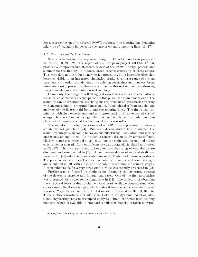
For a representation of the overall FOWT response, the mooring line dynamicsmight be of negligible influence in the case of catenary mooring lines [16, 17].
1.2. Floating wind turbine design
Several schemes for the sequential design of FOWTs have been publishedin [18, 19, 20, 21, 22]. The report of the European project LIFES50+2 [23]provides a comprehensive literature review of the FOWT design process andsummarizes the findings in a consolidated scheme consisting of three stages.This work does not introduce a new design procedure, but a favorable effect thatbecomes visible in an integrated simulation study, covering a range of systemparameters. In order to understand the existing constraints and barriers for anintegrated design procedure, these are outlined in this section, before addressingthe present design and simulation methodology.
Commonly, the design of a floating platform starts with static calculations,the so-called spreadsheet design phase. In this phase, the main dimensions of thestructure can be determined, satisfying the requirement of hydrostatic restoringwith an approximate structural dimensioning. It includes also frequency-domainanalyses of the floater rigid body and the mooring lines. The first stage ter-minates with first experiments and an approximation of the expected cost ofenergy. In the subsequent stage, the first coupled dynamic simulations takeplace, which require a wind turbine model and a controller.
The manifold of design constraints of a FOWT are represented in variousstandards and guidelines [24]. Published design studies have addressed thestructural integrity, dynamic behavior, manufacturing, installation and marineoperations, among others. An academic concept design study across differentplatform types was presented in [25], outlining the main assumptions and designconstraints. A spar platform out of concrete was designed, simulated and testedin [26, 27]. The constraints and options for manufacturing of that design arediscussed and summarized in [28]. A comparable design of reduced draft waspresented in [29] with a focus on seakeeping of the floater and marine operations.The peculiar loads of a steel semi-submersible with submerged counter-weightare calculated in [30] with a focus on the cables, sustaining the counter-weight.A semi-submersible for a very large wind turbine was recently presented in [22].
Further studies focused on methods for obtaining the structural stressesof the floater in extreme and fatigue load cases. One of the first approacheswas presented for a steel semi-submersible in [31]. The difficulty of obtainingthe structural loads is due to the fact that most available coupled simulationcodes assume the floater is rigid, which makes it impossible to calculate internalstresses. Ways to overcome this limitation were presented in [32, 33, 34, 35].These methods involve either additional DoFs of the dynamic model or addi-tional engineering steps in decoupled analyses. Often, the tower-base bendingmoment, which is available in standard simulation models, is taken as repre-
2http://www.lifes50plus.eu, accessed on July 18, 2018.
3
sentative structural load in optimization studies. It is influenced by both, windand wave loads.
First integrated optimization studies for TLPs and spars were presentedin [36]. A coupled frequency-domain model was used to calculate the tower-topacceleration for various shapes of the floating platform and different slack andtaught mooring configurations. Later, optimization studies on spar platformswere presented [37], including load calculations and a cost model. An adaptationof the wind turbine controller was first included using the same simulation modelas in the present work in [38, 39].
A large optimization study across different platform types was publishedin [40] and later extended in [41]. It includes the hull shape and mooring linedesign and a genetic optimizer. In that work, a frequency-domain model is de-rived from the code FAST [3], with a linear representation of the hydrodynamicviscous damping but without representing the wind turbine controller. The ob-jective was also here a low nacelle acceleration, next to the estimated cost. Theobjective of the present work, as well as the design and simulation methodologywill be outlined in the next section.
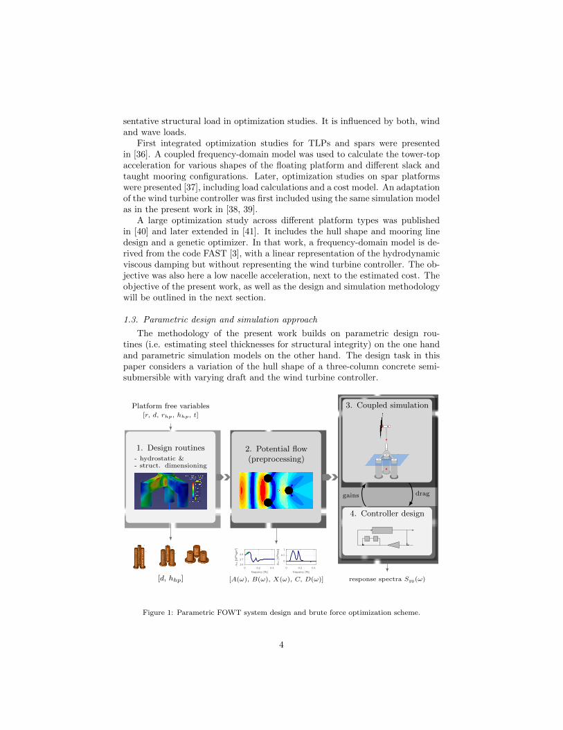
1.3. Parametric design and simulation approach
The methodology of the present work builds on parametric design rou-tines (i.e. estimating steel thicknesses for structural integrity) on the one handand parametric simulation models on the other hand. The design task in thispaper considers a variation of the hull shape of a three-column concrete semi-submersible with varying draft and the wind turbine controller.
Platform free variables[r, d, rhp, hhp, t]
1. Design routines- hydrostatic &- struct. dimensioning
[d, hhp]
2. Potential flow(preprocessing)
frequency [Hz]
B55
[109 N
ms]
frequency [Hz]
A55
[1010
kgm
2 ]
0 0.2 0.40 0.2 0.4
0
0.5
1
2.6
2.7
2.8
[A(ω), B(ω), X(ω), C, D(ω)]
3. Coupled simulation
4. Controller design
response spectra Syy(ω)response spectra Syy(ω)
draggains
Figure 1: Parametric FOWT system design and brute force optimization scheme.
4
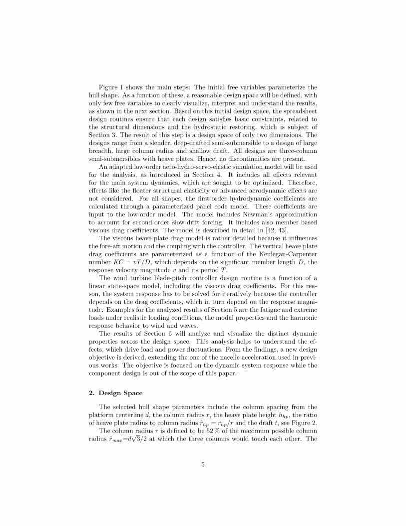
Figure 1 shows the main steps: The initial free variables parameterize thehull shape. As a function of these, a reasonable design space will be defined, withonly few free variables to clearly visualize, interpret and understand the results,as shown in the next section. Based on this initial design space, the spreadsheetdesign routines ensure that each design satisfies basic constraints, related tothe structural dimensions and the hydrostatic restoring, which is subject ofSection 3. The result of this step is a design space of only two dimensions. Thedesigns range from a slender, deep-drafted semi-submersible to a design of largebreadth, large column radius and shallow draft. All designs are three-columnsemi-submersibles with heave plates. Hence, no discontinuities are present.
An adapted low-order aero-hydro-servo-elastic simulation model will be usedfor the analysis, as introduced in Section 4. It includes all effects relevantfor the main system dynamics, which are sought to be optimized. Therefore,effects like the floater structural elasticity or advanced aerodynamic effects arenot considered. For all shapes, the first-order hydrodynamic coefficients arecalculated through a parameterized panel code model. These coefficients areinput to the low-order model. The model includes Newman’s approximationto account for second-order slow-drift forcing. It includes also member-basedviscous drag coefficients. The model is described in detail in [42, 43].
The viscous heave plate drag model is rather detailed because it influencesthe fore-aft motion and the coupling with the controller. The vertical heave platedrag coefficients are parameterized as a function of the Keulegan-Carpenternumber KC = vT/D, which depends on the significant member length D, theresponse velocity magnitude v and its period T .
The wind turbine blade-pitch controller design routine is a function of alinear state-space model, including the viscous drag coefficients. For this rea-son, the system response has to be solved for iteratively because the controllerdepends on the drag coefficients, which in turn depend on the response magni-tude. Examples for the analyzed results of Section 5 are the fatigue and extremeloads under realistic loading conditions, the modal properties and the harmonicresponse behavior to wind and waves.
The results of Section 6 will analyze and visualize the distinct dynamicproperties across the design space. This analysis helps to understand the ef-fects, which drive load and power fluctuations. From the findings, a new designobjective is derived, extending the one of the nacelle acceleration used in previ-ous works. The objective is focused on the dynamic system response while thecomponent design is out of the scope of this paper.
2. Design Space
The selected hull shape parameters include the column spacing from theplatform centerline d, the column radius r, the heave plate height hhp, the ratioof heave plate radius to column radius rhp = rhp/r and the draft t, see Figure 2.
The column radius r is defined to be 52 % of the maximum possible columnradius rmax=d
√3/2 at which the three columns would touch each other. The
5

d
r
hhp
rhp
SWL
t
Figure 2: Free variables for parametric hull shape design, [43].
heave plate-to-column radius ratio is intended to be rhp,in=2 for all designs inorder to ensure that the heave plates are large enough to effectively alter verticaladded mass and Froude-Krylov forces. The heave plate-to-column radius ratio isaltered, however, for the designs where the heave plates of the different columnswould get too close to each other through an exponential function
rhp = rhp/r = (rmax (d)− 1)(1− exp
(rhp,in − 1
rmax − 1
)+ 1. (1)
This ensures that no designs with unrealistically large heave plates result, whichmight not be manufacturable. The distance between overall center of mass andmetacenter GM , i.e. [11], determines the restoring as
C55 = ρgOGM , (2)
with the displaced volume O of density ρ and the gravity constant g. Ballastingis such that zero trim is achieved. Thus, for given column diameters, a re-quired C∗
55 can be obtained by increasing the draft t, which lowers the center ofgravity more than it raises the center of buoyancy and therefore increases C55.
An upper draft limit of 80 m was considered in the a-priori definition of thebounds of the free variables. Hence, any shape considered in this study can bedescribed by the two free variables column spacing d and heave plate height hhp.This means that the design space (of the free variables) is Cartesian and therange of every variable does not depend on the values of the others. The smalldesign space of feasible platforms makes a visualization and thorough analysis ofthe results possible. Table 1 lists the free variables and the dependent variables.
The semi-submersible main dimensions of the 2D design space are shownin Figure 3 with a column spacing range d = 15.0(1.0)24.0 m and a heaveplate height range hhp = 1.0(3.5)8.0 m. The designs range from slender, ratherballast-stabilized towards buoyancy-stabilized shallow-drafted semi-submersibles.Larger column spacings than the ones considered are expected to result in ex-cessive bending stresses in the tripod structure. The variable heave plate heighthas the main effect of modifying the vertical Froude-Krylov forcing. Thus, thisvariable may be able to facilitate the above-mentioned wave cancellation effect.The images on top of Figure 3 show that the column radius is largest for the
6

Table 1: FOWT hull shape design parameters [43].
Free variables Dependent variables• Column spacing d • Column radius r• Heave plate height hhp • Heave plate radius rhp
• Draft t• Steel tripod strut width &
sheet thickness• Ballast mass• Platform mass distribution• Mooring line fairleads position• Wind turbine controller gains
lowest draft. The cost increases generally for increasing column radii r but de-creases for the buoyancy-stabilized ones of shallow draft. The assumptions forthe material cost estimation will be given in Section 3, it is roughly proportionalto the submerged volume. The three designs shown in Figure 3 will be selectedin a number of the upcoming analyses and indicated by “deep draft”, “mediumdraft”, and “shallow draft”.
PSfrag replacements
col. spacing d [m]
sub.
vol.
[1
03m
3]
cost
[Me
]
col.
radiu
sr
[m]
dra
ftt
[m]
15 16 17 18 19 20 21 22 23 24
30
40
1112131468
1012
−80
−60
−40
−20
0
Figure 3: Design space with two dimensions: column spacing from centerline and heave plateheight. Heave plate height hhp = [1.0, 4.5, 8.0] m (increasing darkness), [43].
7
3. Parametric Design Routines
This section addresses the design routines, which determine the dependentvariables of Table 1. It starts with the structural design of the concrete floaterwith the steel tripod on top, followed by the mooring lines and the tower.Hydrostatic computations and the panel code calculations follow thereafter inSections 3.2–3.3. The wind turbine controller is also parameterized and sub-ject of Section 3.4. The wind turbine design, used for all platforms, is theDTU 10 MW Reference Wind Turbine (RWT) of [44].
3.1. Structural design
Design routines, which were developed for the concrete columns, the heaveplates and the steel tripod will be described in this section. The result ofthe structural design calculation is mainly the mass distribution, next to theshape of the hull, which will be input to the coupled simulation model. Theassumed material properties, costs and wall thicknesses of the columns are listedin Table 2, based on [45].
Table 2: Structural design assumptions, [43].
Parameter Unit ValueReinforced concrete average density [kg/m3] 2750.0Steel density [kg/m3] 7750.0Ballast density [kg/m3] 2500.0Processed steel cost [e/t] 4500Processed concrete cost [e/t] 399Concrete column wall thickness [m] 0.6Heave plate upper and lower lid thickness [m] 0.4
3.1.1. Steel tripod
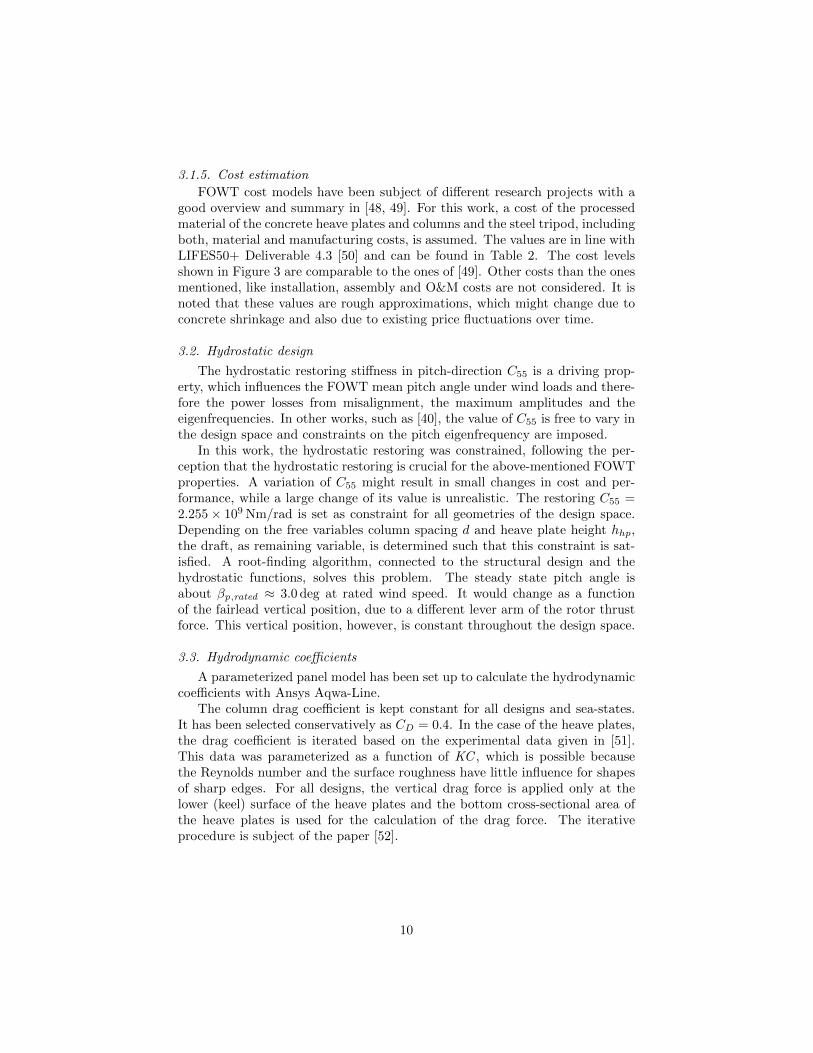
For the steel tripod, various Finite Element (FE) analyses were performed,covering the range of radial distances of the columns d as shown in Figure 3.The results of these calculations allow a parameterization of the dimensions ofthe steel legs like the sheet metal thickness, the strut width and height. Thecalculations assume a static thrust force at the tower-top of 4605 kN, as givenin [44, p. 61]. The notch stress at the joint between the tower and the tripodstruts is assumed to be the critical failure mode. The dimensions of the strutsare determined such that the maximum notch stress is of comparable magnitudeas the one resulting from the same calculation with a comparable commercialtripile. The method was first applied in the European project INNWIND.EU3,of which details can be found in [46]. The dimensions of the tripod of theminimum and maximum column spacing are shown in Table 3.
3http://www.innwind.eu, accessed on July 18, 2018.
8
Table 3: Parametric design of the TripleSpar steel tripod, [43].
Min. column spacing Max. column spacing
50 mm
5 m
60 mm
7 m
Column spacing10.0 m 35.0 m
(distance to center)Strut width & height 5.0 m 7.0 mSteel wall thickness 50 mm 60 mmMaximum stress 146.0 N/mm2 142.0 N/mm2
Tripod mass 447 t 1716 t
3.1.2. Concrete columns and heave plates
The concrete columns are of pre-stressed concrete following the example ofthe AFOSP spar design, see [26]. The cylindric walls have a constant thicknessfor all of the hull shape variations, see Table 2. The heave plates are made outof reinforced concrete with the material properties given in Table 2. The heaveplates are concrete rings, flush mounted to the lower ends of the columns. Thisassumption is rather conservative and accounts for further compartmentationand reinforcements of the detailed design phase.
3.1.3. Mooring lines
The properties of the mooring system can be found in [45]. It was designedfor the TripleSpar design [45, 47], with two upwind lines and one downwind linewith fairleads above Still Water Level (SWL), at zfrlds = 8.7 m and a radialdistance from the tower centerline of dfrlds = 26 m. This large distance makes itpossible to keep the same mooring system for all column spacings d of Figure 3.
3.1.4. Tower
The tower design is not varied in the optimization study but the parametersof the reference TripleSpar are used [45]. For FOWTs it is important that thetower eigenfrequency does not coincide with the Three-Times-Per-Revolution(3p)-frequency range of the rotor. However, the considered platforms of Figure 3show only little variations of the eigenfrequencies. This is mainly due to thehydrostatic design constraints (Section 3.2). Consequently, no adaptation of thetower design is considered in this work.
9
3.1.5. Cost estimation
FOWT cost models have been subject of different research projects with agood overview and summary in [48, 49]. For this work, a cost of the processedmaterial of the concrete heave plates and columns and the steel tripod, includingboth, material and manufacturing costs, is assumed. The values are in line withLIFES50+ Deliverable 4.3 [50] and can be found in Table 2. The cost levelsshown in Figure 3 are comparable to the ones of [49]. Other costs than the onesmentioned, like installation, assembly and O&M costs are not considered. It isnoted that these values are rough approximations, which might change due toconcrete shrinkage and also due to existing price fluctuations over time.
3.2. Hydrostatic design
The hydrostatic restoring stiffness in pitch-direction C55 is a driving prop-erty, which influences the FOWT mean pitch angle under wind loads and there-fore the power losses from misalignment, the maximum amplitudes and theeigenfrequencies. In other works, such as [40], the value of C55 is free to vary inthe design space and constraints on the pitch eigenfrequency are imposed.
In this work, the hydrostatic restoring was constrained, following the per-ception that the hydrostatic restoring is crucial for the above-mentioned FOWTproperties. A variation of C55 might result in small changes in cost and per-formance, while a large change of its value is unrealistic. The restoring C55 =2.255× 10⁹ Nm/rad is set as constraint for all geometries of the design space.Depending on the free variables column spacing d and heave plate height hhp,the draft, as remaining variable, is determined such that this constraint is sat-isfied. A root-finding algorithm, connected to the structural design and thehydrostatic functions, solves this problem. The steady state pitch angle isabout βp,rated ≈ 3.0 deg at rated wind speed. It would change as a functionof the fairlead vertical position, due to a different lever arm of the rotor thrustforce. This vertical position, however, is constant throughout the design space.
3.3. Hydrodynamic coefficients
A parameterized panel model has been set up to calculate the hydrodynamiccoefficients with Ansys Aqwa-Line.
The column drag coefficient is kept constant for all designs and sea-states.It has been selected conservatively as CD = 0.4. In the case of the heave plates,the drag coefficient is iterated based on the experimental data given in [51].This data was parameterized as a function of KC , which is possible becausethe Reynolds number and the surface roughness have little influence for shapesof sharp edges. For all designs, the vertical drag force is applied only at thelower (keel) surface of the heave plates and the bottom cross-sectional area ofthe heave plates is used for the calculation of the drag force. The iterativeprocedure is subject of the paper [52].
10

3.4. Controller design
As introduced in Section 1, the blade pitch controller of the wind turbine forabove-rated wind speeds is critical for the FOWT system stability. In order toensure a properly tuned controller for each of the designs of Figure 3, a methodwas developed to automate the design of a Single-Input-Single-Output (SISO)Proportional-Integral (PI)-controller, depending on the linear dynamic model.This model will be introduced in Section 4. The controller design procedure issubject of the companion paper [53] and part of the thesis [43], which includesa comparison against a multivariable controller.
Figure 1 of Section 1 shows on the right the iterative solution procedure toobtain the controller gains: It follows from the implementation of [52], whichconsiders viscous drag coefficients of the heave plates that are a function of theKC -number, which is itself a function of the nodal response magnitude. Theresulting platform viscous damping eventually determines how aggressive thewind turbine controller can be tuned. Thus, the viscous drag and the bladepitch controller gains are obtained iteratively.
The parameterized control design routine has proven to be valid throughoutthe entire design space of platforms, which was verified through simulations overall operating wind speeds. Especially the rotor speed and power overshoots arefor all platforms within the design space and the metocean conditions of [54,Chap. 7] inside commonly used design constraints.
4. Simulation Model
The numerical FOWT model used for the computation of the load responsein this work was described in [43, 42]. Figure 4 shows a mechanical sketch ofthe Simplified Low-Order Wind Turbine (SLOW) model. The intended purposeof the model is to represent the overall rigid-body and elastic dynamics of thesystem. It shall, on the other side, disregard all effects which increase complexitywithout contributing to the main system response. Through the improvement ofcomputational speed, an efficient calculation of the load response for all designsis possible. The model derivation starts with physical (as opposed to black-box) models, keeping the inherent nonlinearities. Subsequently, these modelsare linearized and the frequency-domain response spectra will be used here,which is subject of Section 5.
The structural model is derived using the theory of flexible MBS. An advan-tage of the implemented algorithm is that the setup of the equations of motionis user-defined. Thus, the multibody structure can be adapted to the analyzedproblem. In this work, the equations of motion have been set up for six DoFsin 2D: The floating platform rigid body in surge (xp), heave (zp) and pitch (βp),a flexible tower with one generalized coordinate xt, the rotor speed Ω and theblade pitch actuator θ1 is selected, see Figure 4. These DoFs are chosen withthe aim of reducing the system to the most important forces and response dy-namics. The largest environmental forces act usually in the direction of windand waves (x).
11

z
x
Ω
θ
y
xt
zp
xp
βp
• Structural dynamics: 6 DoFs, 2D motion
• Aerodynamics: Quasi-static, rotationally sampledturbulence
• Hydrodynamics: 1st-order coefficients, Morisonviscous drag, parametric heave plate drag, simpli-fied radiation, 2nd-order slow-drift approximation
• Mooring dynamics: Quasi-static
• Control: Model-based PI
• Time-domain & frequency-domain
Figure 4: Low-order simulation model SLOW properties. Reprinted from [52] with permissionfrom MDPI, 2018.
The aerodynamic model avoids an iterative solution of the lift and dragforces on the blade sections [55]. Instead, the bulk flow across the entire rotoris considered and the rotor thrust and torque is calculated as function of theTip Speed Ratio (TSR) and the blade pitch angle, using the rotor thrust andpower coefficient. This method neglects azimuth-dependent forcing, especiallythrough wind shears. These are re-introduced through a rotational sampling ofturbulence at the rotor rotational frequency. The method has proven to be agood tradeoff between accuracy and efficiency, especially for the optimizationof the FOWT substructure, as shown in [43].
The hydrodynamic model uses the first-order panel code coefficients anda node-based Morison drag model for a reliable representation of the fore-aftviscous damping, as introduced in Section 1. A significant improvement of thecomputational efficiency is achieved through the frequency-independent addedmass and the neglected radiation damping. It is shown in [43] that radiationdamping is of little influence for the considered platforms, because the dominantforces at the frequencies of nonzero radiation damping are the first-order waveforces. Newman’s approximation [56] is employed to account for low-frequencyslow-drift forcing. The mooring forces result from a quasi-static model.
The nonlinear equations of motion are linearized about all operating points,resulting in a linear state-space description. The aerodynamics are linearizedwith a tangent approximation of the rotor coefficients through a central differ-ence scheme. The quadratic drag is linearized through Borgman’s method [57],using the Standard Deviation (STD) of the platform nodes, obtained from aniterative frequency-domain solution. The linear model is only valid for small
12

deviations of the states from the operating point. For this reason, the analyzedresults focus on operational rather than extreme load cases. To prove the valid-ity of the results, Section 5 will include a comparison against the higher-fidelityFAST model.
5. Load Calculation
This section presents the results of load calculations in operational condi-tions across the design space. First, selected signal statistics will be compared,weighted with the probability of occurrence of each environmental condition overa lifetime of 20 years in the same way as [58]. Thereafter, the frequency-domainresponse will be analyzed and the results will be verified through a comparisonagainst the reference model FAST. A design indicator will be presented at theend of this section, which is able to predict the optimal response behavior.
The environmental conditions of the project LIFES50+ are used with asignificant wave height up to Hs = 8.3 m, see Table 4. For each wind speed,three different peak spectral periods Tp are considered, each with a probability ofoccurrence of 1/3 for the respective mean wind speed. One-hour simulations areperformed with both time-domain models, cutting the transient for statisticalevaluation.
Table 4: Environmental conditions for operational load cases of [54, Chap. 7].
Wind speed v [m/s] 5.0 7.1 10.3 13.9 17.9 22.1 25Significant wave
1.4 1.7 2.2 3.0 4.3 6.2 8.3height Hs [m]Peak spectral
5.0 5.0 5.0 7.0 7.5 10.0 10.0period Tp1 [s]Tp2 [s] 7.0 8.0 8.0 9.5 10.0 12.5 12.0Tp3 [s] 11.0 11.0 11.0 12.0 13.0 15.0 14.0Probability f [%] 14.8 25.0 28.7 17.5 5.9 0.9 0.1
5.1. Operational load response
The linear frequency-domain SLOW model of Section 4 is used to simulatethe response to the metocean conditions of Table 4 for thirty platform designsof the parameter space of Figure 3.
Figure 5 shows the statistical results of the IEC Design Load Case (DLC)1.2 [59], weighted with the Weibull probability density function of Table 4.The Damage-Equivalent Load (DEL) of the tower-base fore-aft bending mo-ment Myt is calculated for a lifetime of 20 years with a Wohler exponent of m =4. The STDs are normalized with the corresponding values for the onshoreDTU 10 MW RWT with the same turbulent wind fields. For onshore turbines,the significant loading through the waves is not present and only the harmonicloads of the Once-Per-Revolution (1p) and 3p-frequencies are the main fatiguedrivers. It can be seen that the weighted DEL of Myt has a minimum at
13

the shallow-draft shape (d = 24 m, hhp = 4.5 m). The same holds for theweighted STD of the rotor speed Ω (which is proportional to the power forabove-rated winds) and the platform pitch angle βp (here the minimum is atthe thinnest heave plate hhp = 1.0 m). The blade pitch activity (θ) is ratherconstant over the design space.
These results show a tower-base bending damage variation of more than 30 %.The fatigue damage is for the optimal design only 50 % greater than for the on-shore turbine, although the wave conditions are rather severe. The estimatedmaterial cost of this design is not significantly higher than the one of the deeperdraft, see Figure 3, although the shallow-draft platform has a large columnspacing of d = 24 m and a column radius of r = 10.8 m with heave platesof rhp = 17.4 m.
column spacing d [m]
ST
D(θ
)[-]
ST
D(Ω
)[-]
column spacing d [m]
ST
D(β
p)
[deg
]D
EL(M
yT
)[-]
16 18 20 22 2416 18 20 22 240.4
0.45
0.5
0.550.8
1
1.2
0.4
0.6
0.81
1.5
2
2.5
Figure 5: Linear response statistics of operational DLC1.2, of [54, Chap. 7], weighted ac-cording to wind speed distribution. DEL/STD are normalized results with correspond-ing FAST onshore simulations of DTU 10 MW RWT with the same wind fields. Heave plateheight hhp = [1.0, 8.0] m (increasing darkness), [43].
Figure 6 shows a comparison of the response spectra of the deep-draft andthe shallow-draft platforms. The shallow-draft shape has a larger difference-frequency and wind-induced response in surge at the lower end of the frequencyaxis. Except for this, the reason for the good performance, indicated by Figure 5,becomes clear: The shallow-draft platform has visibly smaller responses at thepitch eigenfrequency of fd,pitch ≈ 0.04 Hz but, even more importantly, at thefirst-order wave frequencies of 0.1 Hz (vhub = 17.9 m/s, left) and 0.08 Hz (vhub =25 m/s, right). This effect is noticeable for the platform motion response βp buteven more for the tower bending (xt, Myt), the rotor speed Ω and the electricalpower P .
5.2. Comparison of design model and reference model
Figure 7 shows the same response signals as Figure 5 with a comparisonbetween the nonlinear and the linearized SLOW models and the FAST model.
14

v = 25 m/sv = 17.9 m/s
frequency [Hz]frequency [Hz]
twr-
ben
dM
yt
[GN
m2/H
z]
pow
erP
[MW
2/H
z]
bld
ptc
h(θ
)
[deg
2/H
z]
rot-
spd
Ω
[rpm
2/H
z]
twr-
top
xt
[m2/H
z]
pit
chβ
p
[deg
2/H
z]
surg
ex
p
[m2/H
z]
wave
ζ 0
[m2/H
z]
win
dv0
[m2/s2
/H
z]
0 0.05 0.1 0.15 0.20 0.05 0.1 0.15 0.2
10−3
10−1
10−2
101
10−1
102
10−1
101
10−2
100
10−2
102
100
103
100
102
10−1
102
Figure 6: Comparison of deep-draft (spacing d = 15 m, blue) and shallow-draft (spacingd = 24 m, red) platforms for vhub = 17.9 m/s (left) and vhub = 25.0 m/s (right) with PI-controller, computed by FAST, [43].
15

The comparison shows the results of all column spacings d for the flattest heaveplate hhp = 1.5 m and the thickest heave plate hhp = 8 m. The qualitativeoptimum towards large d (shallow drafts) is predicted equally by all models.Consequently, the low-order model is generally suitable for the considered con-ditions and assessed response quantities.
hhp = 8 mhhp = 1 m
col. spacing (from tower centerline) [m]col. spacing (from tower centerline) [m]
ST
D(θ
)
[deg
]
ST
D(Ω
)
[rpm
]
ST
D(β
p)
[deg
]
DE
L(M
yT
)
[GN
m]
16 18 20 22 2416 18 20 22 24
0.5
1
0.4
0.5
0.6
0.4
0.6
0.8
0.2
0.3
Figure 7: Response statistics of operational DLC1.2 with PI-controller, weighted for allwind speeds with distribution. Linear SLOW model (blue), nonlinear SLOW model (red),FAST (green), [43].
There is a constant concept-independent offset of the DEL between theSLOW models and FAST. The reason for this offset is the simplified actua-tor disk model. The excitation of the blades through wind shear is only re-introduced through a rotational sampling of the blade-effective wind at thenominal rotor speed, see [42]. The offset of the rotor speed Ω and blade pitchangle θ is related to the linearized SLOW model. The linearized model under-predicts the variation of the rotor responses because of the nonlinear switchingalgorithm of the controller. The objective of the below-rated controller is tomaximize power production, while the above-rated controller aims at limitingthe power production. The switching between the control regions is a highlynonlinear effect, which cannot be modeled with the linear frequency-domainmodel. It is, however, modeled in the time-domain model, which agrees no-tably better with FAST for Ω and θ. The platform pitch angle variation is wellaligned among the time-domain models with a slight underprediction of SLOWfor the platforms of deep draft. The linearized model underpredicts the pitch-STD for the shallow-draft platforms. This effect is distinct for the two heaveplate heights hhp and might therefore be due to the simplified radiation model,
16

see [42].
5.3. Extreme load response
The load response to IEC DLC 6.1 with 50-year wind and wave conditionsis presented in this section. The reference model FAST was used in this casebecause of large expected excursions, where especially the aerodynamic modelof SLOW might not predict reliable results, due to its simplifications. Turbulentwind and irregular wave timeseries were generated according to [54, p. 58, 64].Figure 8 shows the mean of the maxima of the tower-base bending moment Myt
and the tower-top acceleration xtt (the absolute one, including platform ac-celerations) of three one-hour simulations. The results confirm the findings ofFigure 5: The shallow-draft platform has small tower-top accelerations of lessthan 0.3g. The LIFES50+ design basis [60] would accept these values evenduring operation, while the limits for shut-down conditions are xtt,max = 0.3g.
column spacing d [m]
MA
X(x
tt)
[ms−
2]
column spacing d [m]
MA
X(M
yt)
[MN
m]
16 18 20 22 2416 18 20 22 24
3
4
5
200
300
400
Figure 8: DLC 6.1 extreme sea state with 50-year extreme conditions of v50 = 44 m/s, Hs =10.9 m and Tp = 15 s. Tower-base bending moment (left) and absolute tower-top acceleration(right) simulated with FAST. Heave plate height hhp = 4.5 m.
6. Results Analysis and Design Indicators
A key to understanding the underlying effect for this remarkable ability of theshallow-draft platform (d = 24 m) to reject disturbances is the analysis how thesystem responds to sinusoidal disturbances, meaning regular waves of differentfrequencies or harmonically oscillating wind speed. The ability to reject thesedisturbances will be quantified with a new design indicator at the end of thissection.
6.1. Harmonic response to wind and waves
Figure 9 shows the harmonic response to wind and wave forces. The lines,representing each a different frequency, stand for the FOWT centerline response.The horizontal distance of each point on the lines to the y-axis indicates theamplitude of oscillation of the system response at all elevations z along the cen-terline to sinusoidal wind (upper) and wave excitations (lower). The analysis is
17

made with the low-order linearized model of Section 4 with first-order hydro-dynamics, quasi-static mooring lines, an elastic tower, aerodynamics and thetuned PI-controller at vhub = 13.9 m/s. The centerline amplitude |Φx,i(z, ω)|results from the disturbance transfer function or Response Amplitude Operator(RAO) Gdi,xk
(ω) from wind (i = 1) and waves (i = 2) to the states surge, pitchand tower-bending, represented by xk as
|Φx,i(z, ω)| = |Gdi,xp (ω) +Gdiβp(ω) z +Gdi,xt (ω)ϕx(z)|. (3)
The tower shape function is denoted by ϕx(z).The solid black horizontal lines indicate the overall Center of Mass (CM)
of the FOWT and the dashed line indicates the center of buoyancy. For ships,the instantaneous center of roll motions is usually the metacenter, [61, p. 62].Here, the instantaneous center of rotation in pitch is the vertical location on theplatform with near-zero amplitude. The response to harmonic wind excitationsshows a center of rotation equal to the CM. The same behavior is generallyobservable for all platforms.
The lower part of Figure 9 shows the harmonic response to waves. Here,the instantaneous center of rotation is below the platform-CM for the platformsof deep draft. The platform of the lowest draft (d = 24 m) has a differentbehavior: Its instantaneous center of rotation is at higher elevations, near therotor hub. This is remarkable because it means that the hub does not respondwith a horizontal movement to wave excitations. Consequently, the wind turbinepower production is almost not affected by the waves and the rotor does not seeany platform-induced relative wind speed. The shallow-draft platform respondsin a way that surge is positive, when pitch is negative. Thus, these DoFs are out-of-phase, as opposed to the other platforms, which have an in-phase responseof surge and pitch to waves. Therefore, this optimality cannot be found whenthe surge or pitch RAO is sought to be minimized. The same idea inspired thedevelopers of a TLP platform to arrange the taut mooring lines, such that thesystem is forced to rotate about the hub, see [62]. The fact that this behaviorcan be obtained for semi-submersibles has not been published yet.
The cause leading to this response behavior are the Froude-Krylov pressures,integrated over the hull surface. The coupled magnitude and phases of the force-RAO vector X(ω) are for the optimal shape such that the presented response ofthe FOWT system is obtained. Semi-submersibles are predestined for a “shap-ing” of the force-RAO because the floater members see different phases of thewaves and, additionally, the horizontal (heave plates) and vertical (columns)surfaces experience different phases of the Froude-Krylov pressures, which allowa counter-phase surge and pitch forcing.
Eventually, the shallow-draft platform motion is not constrained but a mo-tion response to mitigate the wave pressures is allowed. Important is the factthat the allowed motion response is favorable, such that the transmissibility ofthe wave forcing towards the wind turbine is reduced. The smaller tower-topmotion yields smaller inertial forces of the Rotor-Nacelle Assembly (RNA). Thebending moments from the gravitational forces of the RNA are reduced because
18

0.095Hz
0.102Hz
0.109Hz
0.116Hz
0.123Hz
0.130Hz
0.137Hz
0.144Hz
0.151Hz
0.158Hz
0.010Hz
0.017Hz
0.024Hz
0.031Hz
0.038Hz
0.045Hz
0.052Hz
0.059Hz
0.066Hz
0.073Hz
d = 24 m, r = 10.8 md = 19 m, r = 8.6 md = 15 m, r = 6.8 m
x [m]
x [m]
x [m]
x [m]
x [m]
harm
onic
resp
onse
tounit
wave
z[m
]
x [m]
harm
onic
resp
onse
tounit
win
d
z[m
]
0 0.5 1
0 5 10
0 1 2
0 10 20
0 1 2
0 10 20
-60
-40
-20
SWL
20
40
60
80
100
hub
140
160
-60
-40
-20
SWL
20
40
60
80
100
hub
140
160
Figure 9: Harmonic response of FOWT system over typical wind frequencies (top) and wavefrequencies (bottom) at v0 = 13.9 m/s with heave plate height hhp = 4.5 m. Solid black line:FOWT overall center of mass, dashed black line: center of buoyancy, [43].
19

the platform pitch angle is also smaller for the shallow-draft design (Figure 5).The aerodynamic damping forces are not significant at the wave frequencies [63].In conclusion, the stationary hub does not only yield a smooth power produc-tion but also reduced tower-base bending moments. Small adjustments in theoptimal harmonic response shape can be expected when taking other outputs,like the mooring fatigue, into account.
The “counter-phase pitch response” of Figure 9 is important for the con-troller design: Because of the minimal motion response at the hub, the powerfluctuations are reduced. Also, the coupling of the substructure dynamics withthe controller is reduced. Common controllers feed back the rotor speed devia-tion from the set point. If the rotor responds less to the wave forces, there willbe less wave-induced rotor speed deviation and the wave response will not beamplified by the controller as with regular FOWT platforms. It is emphasizedthat the harmonic response is not to be confused with the modal response toturbulence and slow-drift forces. This one can be well damped by wind turbinecontrollers, which feed back a fore-aft velocity signal, as in [64], [65] or [66].It was shown in [64, 63] that the system response to first-order waves cannotbe damped by the controller because of their large magnitude. Consequently,the shaping of the hull which yields the favorable first-order wave response canbe effectively complemented by a controller, which damps the low-frequencymotion response.
The sensitivity of this behavior to the peak spectral wave period Tp is ob-vious from Figure 9. Thus, the favorable design is site-dependent. It can beseen, however, that the sensitivity is not very pronounced, meaning that theinstantaneous center of rotation does not move significantly as a function of thewave frequency. This shows a certain robustness of the response behavior interms of the environmental conditions.
6.2. Design indicator: Minimum required control action
The harmonic response of Figure 9 helps to understand the reason for thefavorable behavior of the shallow-draft platforms. In this section, a new designindicator will be introduced to generally judge the goodness of a platform interms of its induced wind turbine response. The idea is to quantify the nec-essary controller action to perfectly cancel the external forcing from wind andwaves. The smaller the controller activity, the better the capability of the de-sign to inherently reject disturbances itself. Figure 10 shows the linear FOWTsystem transfer function in the Laplace domain G(jω) with additive distur-bance transfer functions Gd,i for the control inputs generator torque and bladepitch angle u = [Mg, θ]
T and the outputs rotor speed and tower-top bend-ing y = [Ω, xt]
T . Both, the plant G(jω) and the disturbance transfer functionfor wind Gd,v0(jω) and the one for waves Gd,ζ(jω), collected in Gd, are ob-tained from the linear SLOW model and scaled as in [63]. This is convenient asit means that a response yi ≥ 1 exceeds the design limits, see [67].
In order to quantify the impact of disturbances on a linear system, Sko-gestad [68] calculates the 2-norm of the control input, theoretically necessary
20

θ
v0
G(jω)
ΩMg
ζ0
xt
Gd,1 Gd,2
Figure 10: FOWT square plant with additive disturbances.
to perfectly cancel the disturbances. This analysis does not consider the con-troller dynamics but only the actuator authority on the system response. Therequired control input u can be obtained, given a disturbance d, through systeminversion as
u = −G−1(jω)Gd(jω)d. (4)
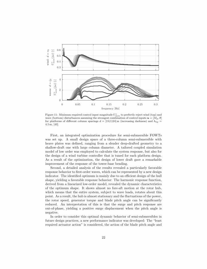
The least necessary actuation4 has been calculated for the different plat-forms for the wind excitation d = v0 = 1 and wave excitation d = ζ0 = 1independently in Figure 11. The part from wind excitation (upper part of Fig-ure 11) does not show a large variation over the different platforms, except forthe changing eigenfrequencies. It is different for the wave excitation: The bestperformance (equal to the least required actuation U∗
min) results here for thelargest column spacing d = 24 m. Consequently, the assessment of the minimumrequired control input can well predict the optimality of the semi-submersibles,seen in the Figure 5 and 9.
This indicator allows a general quantification of the ability of a FOWTplatform to support a wind turbine without transmitting detrimental externalexcitation forces. It is the basis for a platform design, particularly adapted tothe requirements of the wind turbine.
Parameters of optimum design. A FAST model of the optimum shape can bedownloaded [69]. The hull shape has a column radius of r = 10.81 m, a spacingfrom the centerline of d = 24 m a heave plate thickness of hhp = 4.5 m a draftof t = 21.94 m. The platform has a mass including ballast of m = 3.115× 10⁴ tand a center of mass below SWL of zcm,ptfm = 13.36 m.
7. Conclusions
The study can be summarized by two parts:
4Calculated for both control inputs u, assuming the most effective combination of them,through a Singular Value Decomposition (SVD) of G. U∗
min(ω) is the 2-norm of the controlinput vector.
21
PSfrag replacements
frequency [Hz]
waves
:d
=ζ 0
U∗ m
in(j
ω)
[-]
win
d:
d=
v0
U∗ m
in(j
ω)
[-]
0 0.05 0.1 0.15 0.2 0.25 0.3
0
2
4
0.3
0.4
0.5
0.6
Figure 11: Minimum required control input magnitude U∗min to perfectly reject wind (top) and
wave (bottom) disturbances assuming the strongest combination of control inputs u = [Mg , θ]for platforms of different column spacings d = [15(1)24] m (increasing darkness) and hhp =4.5 m, [43].
First, an integrated optimization procedure for semi-submersible FOWTswas set up. A small design space of a three-column semi-submersible withheave plates was defined, ranging from a slender deep-drafted geometry to ashallow-draft one with large column diameter. A tailored coupled simulationmodel of low order was employed to calculate the system response, but also forthe design of a wind turbine controller that is tuned for each platform design.As a result of the optimization, the design of lower draft gave a remarkableimprovement of the response of the tower-base bending.
Second, a detailed analysis of the results revealed a particularly favorableresponse behavior to first-order waves, which can be represented by a new designindicator. The identified optimum is mainly due to an efficient design of the hullshape, yielding a favorable response behavior: The harmonic response function,derived from a linearized low-order model, revealed the dynamic characteristicsof the optimum shape. It shows almost no fore-aft motion at the rotor hub,which means that the entire system, subject to wave loads, rotates about thispoint. As a result, the hub is almost stationary and the fluctuations of the power,the rotor speed, generator torque and blade pitch angle can be significantlyreduced. An interpretation of this is that the surge and pitch response areout-of-phase, yielding a positive surge displacement when the pitch angle isnegative.
In order to consider this optimal dynamic behavior of semi-submersibles infuture design practices, a new performance indicator was developed: The “leastrequired actuator action” is considered, the action of the blade pitch angle and
22

generator torque. Their magnitude, necessary to reject the wave loads, is anindicator, which can effectively predict how well a floating platform is able toinherently reject disturbances itself, without transmitting them to the windturbine.
The study showed that it is possible to design a FOWT platform, specificallysuitable to carry a wind turbine, minimizing the effect of the waves on thepower production. While the first-order wave loads cannot be mitigated bythe controller, a further improvement of the low-frequency response behaviorthrough the controller is possible. The presented harmonic response graph canbe a good means for the selection of additional feedback loops. Although thecost model of this work is simple, the work follows the idea that a smoothbehavior in harsh met-ocean conditions is a key for a sustainable and low-costFOWT design.
Further studies will address the impact of the counter-phase response on themooring line loads and integrate them into an optimization process.
Acknowledgements
The research leading to these results has received funding from the Euro-pean Union’s Horizon 2020 research and innovation programme under grantagreement No. 640741 (LIFES50+).
References
[1] A. Henderson, Analysis tools for large floating offshore wind farms, Ph.D.thesis, University College London (2000).
[2] J. O. G. Tande, K. Merz, U. S. Paulsen, H. G. Svendsen, Floating offshoreturbines, Wiley Interdisciplinary Reviews: Energy and Environment 4 (3)(2015) 213–228. doi:10.1002/wene.130.
[3] NWTC, NWTC information portal (FAST v8) (2016).URL https://nwtc.nrel.gov/FAST8
[4] J. Jonkman, Influence of control on the pitch damping of a floating windturbine, in: Proceedings of the 46th AIAA Aerospace Sciences Meeting andExhibit, AIAA, Reno, USA, 2008. doi:10.2514/6.2008-1306.
[5] T. J. Larsen, T. D. Hanson, A method to avoid negative damped low fre-quent tower vibrations for a floating, pitch controlled wind turbine, Journalof Physics: Conference Series 75. doi:10.1088/1742-6596/75/1/012073.
[6] M. O. L. Hansen, Influence of rigid body motions on rotor induced ve-locities and aerodynamic loads of a floating horizontal axis wind tur-bine, in: Proceedings of the ASME 33rd International Conference onOcean, Offshore and Arctic Engineering, San Francisco, USA, 2014. doi:
10.1115/OMAE2014-24227.
23

[7] T. T. Tran, D. H. Kim, The platform pitching motion of floating offshorewind turbine: A preliminary unsteady aerodynamic analysis, Journal ofWind Engineering and Industrial Aerodynamics 142 (2015) 65–81. doi:
10.1016/j.jweia.2015.03.009.
[8] M. Lennie, D. Marten, G. Pechlivanoglou, C. N. Nayeri, C. O. Paschereit,Modern methods for investigating the stability of a pitching floating plat-form wind turbine, Wind Energy Science 2 (2) (2017) 671–683. doi:
10.5194/wes-2-671-2017.
[9] D. Matha, F. Lemmer, M. Muskulus, Offshore turbines with bottom-fixedor floating substructures, in: P. Veers (Ed.), Wind Energy Modeling andSimulation - Volume 2: Turbine and System, The IET, 2019. doi:10.
1049/PBPO125G_ch5.
[10] J. Journee, W. W. Massie, Offshore Hydromechanics, 1st Edition, DelftUniversity of Technology, 2001.URL https://ocw.tudelft.nl/wp-content/uploads/
OffshoreHydromechanics_Journee_Massie.pdf
[11] M. E. McCormick, Ocean Engineering Mechanics, Cambridge UniversityPress, New York, 2010.
[12] O. M. Faltinsen, Sea Loads On Ships And Offshore Structures, CambridgeUniversity Press, 1993.
[13] T. Duarte, A. Sarmento, J. Jonkman, Effects of second-order hydrodynamicforces on floating offshore wind turbines, in: Proceedings of the AIAASciTech, National Harbor, USA, 2014. doi:10.2514/6.2014-0361.
[14] S. Y. Hanna, Wave cancellation effects and extreme wave dynamics, in:Proceedings of the Offshore Technology Conference, Houston, USA, 1986.
[15] M. H. Patel, Dynamics of offshore structures, 1st Edition, Butterworths,London, 1989.
[16] J. Azcona, D. Palacio, X. Munduate, L. Gonzalez, T. A. Nygaard, Im-pact of mooring lines dynamics on the fatigue and ultimate loads ofthree offshore floating wind turbines computed with IEC 61400-3 guide-line, Wind Energy 20 (5) (2016) 797–813. arXiv:arXiv:1006.4405v1,doi:10.1002/we.2064.
[17] D. Matha, Impact of aerodynamics and mooring system on dynamic re-sponse of floating wind turbines, Ph.D. thesis, University of Stuttgart(2016).
[18] F. Huijs, J. Mikx, F. Savenije, E.-J. D. Ridder, Integrated design of floater,mooring and control system for a semi-submersible floating wind turbine,in: Proceedings of the European Wind Energy Association Offshore WindConference and Exhibition, 2013.
24
[19] J. Azcona, D. Bekiropoulos, H. Bredmose, A. Fischer, N. F. Heilskov,A. Krieger, T. Lutz, A. Manjock, D. Manolas, D. Matha, K. Meister,R. Pereira, J. Ronby, F. Sandner, S. Voutsinas, INNWIND.EU D4.21:State-of-the-art and implementation of design tools for floating structures,Tech. Rep. November, INNWIND.EU (2013).
[20] J. Fernandez, A. Laidler, J. Izarra, M. Innovation, D. Murueta, B. Mal-loape, Design considerations of a semisubmersible platform for offshorewind turbines, in: Proceedings of the European Wind Energy AssociationOffshore Wind Conference and Exhibition, 2013.
[21] A. Crozier, Design and dynamic modeling of the support structure for a10MW offshore wind turbine (2011).
[22] J. Liu, E. Thomas, L. Manuel, D. Griffith, K. Ruehl, M. Barone, Inte-grated system design for a large wind turbine supported on a moored semi-submersible platform, Journal of Marine Science and Engineering 6 (1)(2018) 9. doi:10.3390/jmse6010009.
[23] K. Muller, F. Lemmer, F. Borisade, M. Kretschmer, J. Gruber, L. Hage-mann, N.-D. Nguyen, L. Vita, LIFES50+ D7.4 State-of-the-art FOWTdesign practice and guidelines, Tech. rep., University of Stuttgart (2015).URL http://lifes50plus.eu/wp-content/uploads/2015/11/GA_
640741_LIFES50_D7.4.pdf
[24] M. Atcheson, A. Garrad, L. Cradden, A. Henderson, D. Matha, J. Nichols,D. Roddier, J. Sandberg, Floating Offshore Wind Energy, Springer, 2016.
[25] S. Lefebvre, M. Collu, Preliminary design of a floating support structurefor a 5MW offshore wind turbine, Ocean Engineering 40 (2012) 15–26.doi:10.1016/j.oceaneng.2011.12.009.URL http://linkinghub.elsevier.com/retrieve/pii/
S0029801811002769
[26] C. Molins, A. Campos, F. Sandner, D. Matha, Monolithic concrete off-shore floating structure for wind turbines, in: Proceedings of the EuropeanWind Energy Association Annual Event, Barcelona, Spain, 2014.
[27] D. Matha, F. Sandner, C. Molins, A. Campos, P. W. Cheng, Efficientpreliminary floating offshore wind turbine design and testing methodologiesand application to a concrete spar design, Philosophical Transactions of theRoyal Society A 373 (2035). doi:10.1098/rsta.2014.0350.
[28] C. Molins, A. Yague, P. Trubat, Construction possibilities for monolithicconcrete spar buoy serial production, Journal of Physics: Conference Series1104 (2018) 012020. doi:10.1088/1742-6596/1104/1/012020.
[29] S. de Guzman, D. Maron, P. Bueno, M. Tabaoda, M. Moreu, A reduceddraft spar concept for large offshore wind turbines, in: Proceedings of the
25

ASME 37th International Conference on Ocean, Offshore and Arctic Engi-neering, Madrid, Spain, 2018. doi:10.1115/OMAE2018-77787.
[30] B. Pereyra, Z. Jiang, Z. Gao, M. T. Andersen, H. Stiesdal, Parametricstudy of a counter weight suspension system for the tetraspar floating windturbine, in: Proceedings of the ASME 2018 1st International Offshore WindTechnical Conference, ASME, San Francisco, USA, 2018.
[31] A. Aubault, C. Cermelli, D. Roddier, Windfloat: A floating foundationfor offshore wind turbines part III: Structural analysis, in: Proceedings ofthe ASME 28th International Conference on Ocean, Offshore and ArcticEngineering, 2009. doi:10.1115/OMAE2009-79232.
[32] C. Luan, Z. Gao, T. Moan, Modelling and analysis of a semi-submersiblewind turbine with a central tower with emphasis on the brace system,in: Proceedings of the ASME 32nd International Conference on Ocean,Offshore and Arctic Engineering, ASME, Nantes, France, 2013. doi:10.
1115/OMAE2013-10408.
[33] C. Luan, Z. Gao, T. Moan, Development and verification of a time-domainapproach for determining forces and moments in structural components offloaters with an application to floating wind turbines, Marine Structures51 (2017) 87–109. doi:10.1016/j.marstruc.2016.10.002.
[34] M. Borg, H. Bredmose, A. M. Hansen, Elastic deformations of floaters foroffshore wind turbines: dynamic modelling and sectional load calculations,in: Proceedings of the ASME 36th International Conference on Ocean,Offshore and Arctic Engineering, Trondheim, Norway, 2017. doi:10.1115/OMAE2017-61466.
[35] T. A. Nygaard, Design, analysis and wave tank testing of a semi-submersible braceless concrete offshore wind turbine platform, in: EERADeepwind, Trondheim, Norway, 2015.URL http://www.sintef.no/Projectweb/Deepwind_2015/
Presentations/
[36] P. D. Sclavounos, C. Tracy, S. Lee, Floating offshore wind turbines: Re-sponses in a seastate, pareto optimal designs and economic assessment,in: Proceedings of the ASME 27th International Conference on OffshoreMechanics and Arctic Engineering, 2007. doi:10.1115/OMAE2008-57056.
[37] I. Fylling, P. A. Berthelsen, Windopt – An optimization tool for float-ing support structures for deep water wind turbines, in: Proceedings ofthe ASME 30th International Conference on Ocean, Offshore and Arc-tic Engineering, ASME, Rotterdam, Netherlands, 2011. doi:10.1115/
OMAE2011-49985.
26
[38] F. Sandner, D. Schlipf, D. Matha, P. W. Cheng, Integrated optimizationof floating wind turbine systems, in: Proceedings of the ASME 33rd In-ternational Conference on Ocean, Offshore and Arctic Engineering, SanFrancisco, USA, 2014. doi:10.1115/OMAE2014-24244.
[39] F. Lemmer, K. Muller, W. Yu, D. Schlipf, P. W. Cheng, Optimizationof floating offshore wind turbine platforms with a self-tuning controller,in: Proceedings of the ASME 36th International Conference on Ocean,Offshore and Arctic Engineering, Trondheim, Norway, 2017. doi:10.1115/OMAE2017-62038.
[40] M. Hall, B. Buckham, C. Crawford, Evolving offshore wind: A geneticalgorithm-based support structure optimization framework for floatingwind turbines, in: Proceedings of the OCEANS MTS/IEEE, IEEE, Bergen,Norway, 2013. doi:10.1109/OCEANS-Bergen.2013.6608173.
[41] M. Karimi, Frequency Domain Modeling and Multidisciplinary DesignOptimization of Floating Offshore Wind Turbines, Ph.D. thesis, Universityof Victoria, Canada (2018).URL https://www.researchgate.net/publication/328575575_
Frequency_domain_modeling_and_multidisciplinary_design_
optimization_of_floating_offshore_wind_turbines
[42] F. Lemmer, W. Yu, B. Luhmann, D. Schlipf, P. W. Cheng, Multibody mod-eling for concept-level floating offshore wind turbine design, Multibody Sys-tem Dynamics 49 (2) (2020) 203–236. doi:10.1007/s11044-020-09729-x.
[43] F. Lemmer, Low-Order Modeling, Controller Design and Optimization ofFloating Offshore Wind Turbines, Ph.D. thesis, University of Stuttgart(2018).
[44] C. Bak, F. Zahle, R. Bitsche, T. Kim, A. Yde, L. Henriksen, M. H. Hansen,J. Blasques, M. Gaunaa, A. Natarajan, The DTU 10-MW Reference WindTurbine, Tech. rep., Technical University of Denmark, Roskilde, Denmark(2013).URL https://orbit.dtu.dk/en/publications/
the-dtu-10-mw-reference-wind-turbine
[45] F. Lemmer, K. Muller, A. Pegalajar-Jurado, M. Borg, H. Bredmose,LIFES50+ D4.1: Simple numerical models for upscaled design, Tech. rep.,University of Stuttgart (2016).URL https://lifes50plus.eu/wp-content/uploads/2018/04/
LIFES50_D4-1_final_rev1_public.pdf
[46] F. Sandner, W. Yu, D. Matha, J. Azcona, X. Munduate, E. Grela,S. Voutsinas, A. Natarajan, INNWIND.EU D4.33: Innovative concepts forfloating structures, Tech. rep., University of Stuttgart (2014).URL http://www.innwind.eu/-/media/Sites/innwind/
27

Publications/Deliverables/DeliverableD4-33_
Innovative-Concepts-for-Floating-Structures_INNWIND-EU
[47] H. Bredmose, F. Lemmer, M. Borg, A. Pegalajar-Jurado, R. F. Mikkelsen,T. Stoklund Larsen, T. Fjelstrup, W. Yu, A. K. Lomholt, L. Boehm, J. Az-cona, The TripleSpar campaign: Model tests of a 10MW floating windturbine with waves, wind and pitch control, Energy Procedia 137 (2017)58–76. doi:10.1016/j.egypro.2017.10.334.
[48] G. Benveniste, M. Lerch, M. de Prada, M. Kretschmer, J. Berque,A. Lopez, G. Perez-Moran, LIFES50+ D2.2 LCOE tool description,technical and environmental impact evaluation procedure, Tech. rep.,Catalonia Institute for Energy Research, Barcelona, Spain (2015).URL http://lifes50plus.eu/wp-content/uploads/2016/10/GA_
640741_D2.2-internal.pdf
[49] M. Lerch, M. De-Prada-Gil, C. Molins, G. Benveniste, Sensitivity analysison the levelized cost of energy for floating offshore wind farms, SustainableEnergy Technologies and Assessments 30 (2018) 77–90. doi:10.1016/j.
seta.2018.09.005.
[50] F. Lemmer, K. Muller, W. Yu, R. Faerron-Guzman, M. Kretschmer,LIFES50+ D4.3 Optimization framework and methodology for optimizedfloater design, Tech. rep., University of Stuttgart (2016).URL http://lifes50plus.eu/wp-content/uploads/2015/11/GA_
640741_LIFES50_D4.3-web.pdf
[51] L. Tao, D. Dray, Hydrodynamic performance of solid and porous heaveplates, Ocean Engineering 35 (10) (2008) 1006–1014. doi:10.1016/j.
oceaneng.2008.03.003.
[52] F. Lemmer, W. Yu, P. W. Cheng, Iterative frequency-domain response offloating wind turbines with parametric drag, Journal of Marine Science andEngineering 6 (4). doi:10.3390/jmse6040118.
[53] F. Lemmer, W. Yu, D. Schlipf, P. W. Cheng, Robust gain scheduling base-line controller for floating offshore wind turbines, Wind Energy 23 (1).doi:10.1002/we.2408.
[54] A. Krieger, G. K. V. Ramachandran, L. Vita, P. Gomez Alonso, J. Berque,G. Aguirre-Suso, LIFES50+ D7.2 Design basis, Tech. rep., DNV-GL(2016).URL http://lifes50plus.eu/wp-content/uploads/2015/11/D72_
Design_Basis_Retyped-v1.1.pdf
[55] M. O. L. Hansen, Aerodynamics of Wind Turbines, 2nd Edition, Earthscan,2000.
28

[56] R. Standing, W. Brendling, D. Wilson, Recent developments in the analysisof wave drift forces, low-frequency damping and response, in: Proceedingsof the Offshore Technology Conference, Houston, USA, 1987. doi:10.
4043/5456-MS.
[57] L. E. Borgman, The spectral density for ocean wave forces,in: Proceedings of the Santa Barbara Coastal Engineering Con-ference, Santa Barbara, USA, 1965, pp. 147–182. arXiv:uuid:
ad7a5c81-2a6e-45dc-868d-1cce4fd95df1.
[58] E. Smilden, E. E. Bachynski, A. Sørensen, Key contributors to lifetimeaccumulated fatigue damage in an offshore wind turbine support structure,in: Proceedings of the ASME 36th International Conference on Ocean,Offshore and Arctic Engineering, Trondheim, Norway, 2017. doi:10.1115/OMAE2017-61708.
[59] IEC, 61400-3 Wind turbines - Part 3: Design requirements for offshorewind turbines (2007).
[60] G. Ramachandran, L. Vita, A. Krieger, K. Mueller, Design basis for thefeasibility evaluation of four different floater designs, Energy Procedia 137(2017) 186–195. doi:10.1016/j.egypro.2017.10.345.
[61] T. Fossen, Handbook of Marine Craft Hydrodynamics and Motion Control,1st Edition, John Wiley and Sons, 2011. doi:10.1002/9781119994138.
[62] C. Melis, F. Caille, T. Perdrizet, Y. Poirette, P. Bozonnet, A novel tension-leg application for floating offshore wind: Targeting lower nacelle motions,in: Proceedings of the ASME 35th International Conference on Ocean,Offshore and Arctic Engineering, Busan, South Korea, 2016. doi:10.1115/OMAE2016-54961.
[63] F. Lemmer, D. Schlipf, P. W. Cheng, Control design methods for float-ing wind turbines for optimal disturbance rejection, Journal of Physics:Conference Series 753. doi:10.18419/opus-8906.
[64] P. Fleming, A. Peiffer, D. Schlipf, Wind turbine controller to mitigatestructural loads on a floating wind turbine platform, in: Proceedings ofthe ASME 35th International Conference on Ocean, Offshore and ArcticEngineering, Busan, Korea, 2016. doi:10.1115/OMAE2016-54536.
[65] J. Olondriz, I. Elorza, C. Calleja, J. Jugo, A. Pujana, Platform negativedamping, blade root and tower base bending moment reductions with anadvanced control technique, in: Proceedings of the WindEurope Conferenceand Exhibition, Amsterdam, Netherlands, 2017.
[66] W. Yu, F. Lemmer, D. Schlipf, P. W. Cheng, B. Visser, H. Links, N. Gupta,S. Dankelmann, B. Counago, J. Serna, Evaluation of control methods forfloating offshore wind turbines, Journal of Physics: Conference Series 1104(2018) 012033. doi:10.1088/1742-6596/1104/1/012033.
29

[67] S. Skogestad, I. Postlethwaite, Multivariable Feedback Control: Analysisand Design, 2nd Edition, John Wiley and Sons, Chichester, 2007.
[68] S. Skogestad, E. Wolff, Controllability measures for disturbance rejection,Journal of Modeling, Identification and Control 17 (3) (1996) 167–182.doi:10.4173/mic.1996.3.1.
[69] F. Lemmer, K. Muller, W. Yu, FAST model of the SWE-CPP semi-submersible floating wind turbine platform for the DTU 10MW referencewind turbine (2020). doi:10.18419/darus-621.
30