Embed Size (px)
Citation preview
American Journal of Embedded Systems and Applications 2014; 2(3): 21-28 Published online June 30, 2014 (http://www.sciencepublishinggroup.com/j/ajesa) doi: 10.11648/j.ajesa.20140203.12
Design and development of a project-based embedded system laboratory using PIC 18F25K20
Rajeswari Cherukuri1, Raghavendra Rao Kanchi
2, *
1Research Student, VLSI & Embedded System Laboratory, Sri Krishnadevaraya University, Anantapuramu, 515003, INDIA 2Chairman, BOS in Physics, VLSI & Embedded System Laboratory, Sri Krishnadevaraya University, Anantapuramu, 515003, INDIA
Email address: [email protected] (R. R. Kanchi)
To cite this article: Rajeswari Cherukuri, Raghavendra Rao Kanchi. Design and Development of a Project-Based Embedded System Laboratory Using PIC
18F25K20. American Journal of Embedded Systems and Applications. Vol. 2, No. 3, 2014, pp. 21-28. doi: 10.11648/j.ajesa.20140203.12
Abstract: In this paper we present experiments and projects which gives hands-on experience to the students who start
working with microcontrollers initially. As PIC microcontrollers have become popular and are one of the best
microcontrollers to start working with in an introductory embedded system laboratory, we have chosen PIC 18F25K20
microcontroller available on the market in a palm size module by name: AMICUS. The exercises described in this paper can
be introduced as a one-third semester laboratory course. The AMICUS module is inexpensive and can be used to perform
basic and project-based exercises. It is well suited for an under graduate engineering or science course, with electronics,
computer science as major. If it is a introductory laboratory course on microcontrollers, it gives an opportunity for the student
to use his previous knowledge on basic electronic circuits, digital system design, computer architecture and software
development. This paper is not only useful for academics but also useful for amateur electronics hobbyist.
Keywords: Embedded System Laboratory, PIC 18F25K20, Project-Based Experiments
1. Introduction
We have communicated a couple of papers [1, 2] to this
journal, describing the methodology to get acquainted
with different advanced microcontrollers, which paves path
for designing an embedded system laboratory. Indeed it is
not only useful for academics, but also for amateur
electronics hobbyist to learn using microcontrollers, which
is the heart of the embedded system design. We received
appreciation mails on these papers. Continuing in this
direction, we have chosen designing with PIC
microcontrollers which are widely used in industry, robotics
and entertainment.
The technological advancement in the field of
system-on-chip (SOC) has lead to the design and
development of embedded systems. Further, the
proliferation of such embedded systems in diversified fields
has already begun. Embedded systems are widely used in
cellular phones, digital cameras, home appliances, human
healthcare, structure health monitoring systems, space
applications up to ubiquitous computing. Looking from
this perspective, it is the need of the hour to bring out young
engineers who can take up challenging jobs in industry.
Looking from the industrial perspective, the outgoing
student should have been exposed to team work, reasonably
complex projects, in addition to the subject knowledge.
This calls for practical and application-oriented training in
education, with cooperative problem solving. If the course
work satisfies all these aspects, the student can learn faster
in the presence of team work and develop leadership
qualities.
Research work was also carried out in different fields
using PIC18F25K20 [3-7]. Keeping these facts in view
point, we have developed more than a dozen of interfacing
experiments using microchip low-power mixed signal
controller PIC 18F25K20. Of course, microcontrollers with
advanced architecture are also available. Our aim is to start
humbly, with a simple microcontroller and then move to
complex architectures.
In this paper, we used Amicus 18 development board; it
was purchased from NSK Electronics, Bangalore [8].
Amicus 18 is an embedded system platform based on a
simple open hardware design for a single-board
microcontroller, with embedded I/O support and a standard
programming language. The programming language is a
version of Crownhill’s proton BASIC. Amicus 18 is used to
22 Rajeswari Cherukuri and Raghavendra Rao Kanchi: Design and Development of a Project-Based Embedded System Laboratory Using PIC 18F25K20
develop stand-alone interactive objects or it can be
connected to a host computer. An Amicus 18 board consists
of an 8-bit microchip PIC microcontroller: 18F25K20, with
complementary components to facilitate programming and
incorporation in to other circuits. The board includes both
5V and 3V linear regulators and a 16 MHz crystal oscillator,
thus allowing 16-MIPS operation. The Amicus 18’s
microcontroller (18F25K20) is also pre-programmed with a
boot-loader that simplifies uploading of programs to the
on-chip flash memory compared to other devices that
typically need an external chip programmer; Amicus 18 can
be programmed via a USB cable that also serves as a means
of power and communication to the board.
The Amicus 18 board is extremely easy to use; in fact, no
previous microcontroller’s experience is required in order
to get the first project started up and running. Figure 1
shows the Amicus 18 development board.
Fig. 1. Amicus 18 Development Board.
The experiments presented in this paper start with LED
interfacing and goes up to the projects with interfacing of
sensors. The systematic approach of learn-while-doing
increase the confidence in students. Further, majority of the
components used in the present work are off the shelf or
low-cost, hence students can purchase on their own [9].
The experiments explained here, can also be useful for
fresh research and graduate students who wants to work in
the fields of instrumentation and electronics.
PIC 18F25K20 microcontroller is mixed signal controller
that posses high processing power and sufficient on-chip
memory. The hardware designed for experiments consume
less power, and hence can be operated using battery.
Further, it also occupies less space and function properly in
real-time. These are the best qualifications for embedded
system design.
This paper is organized as: Section-2 gives brief
description of the architectural details of PIC 18F25K20
microchip mixed signal controller and programming
procedure of the controller using proton BASIC. Section-3
gives the details of hardware and software, developed in the
present study. Conclusions and scope for future work are
included in Section 4.
2. Architecture and Programming
Procedure using Proton BASIC
2.1. Architecture of PIC 18F25K20
The PIC 18F25K20 is an 8-bit mixed signal controller
from Microchip, and is one of the most widely used
microcontroller in a number of embedded system
applications such as automobiles, industrial control etc.
PIC 18F25K20 microcontroller offers low power
consumption. It is this microcontroller used on the Amicus
18 board has 32768 bytes of flash memory, 1536 bytes of
RAM, and operates at 64 MHz.
It has different power management modes, like: run, idle,
and sleep, with two speed oscillation start up. It has four
different timers, called Timer 0, Timer 1, Timer 2, and Timer
3, and also supports a sleep and watchdog timer. On utilizing
these timers, the sensor node can be kept working for a
longer period of time [10]. Other important features are:
→ It has high performance RISC CPU up to 16-MIPS
operation.
→ It has flexible oscillator structure with 16MHz
oscillator.
The on-chip peripheral components of the PIC 18F25K20
include: 12 10-bit Analog-to-Digital converter channels,
2-Analog comparator module, Two 10-bit PWM outputs, A
USART, SPI, I2C and 4-timers [11]. It supports the
operating system such as windows. Figure 2 shows the
internal architecture of PIC 18F25K20
Fig. 2. Internal Architecture of PIC 18F25K20.
2.2. Programming Procedure using Proton BASIC with
Amicus IDE
The proton Amicus 18 IDE is a professional and powerful
Integrated Development Environment (IDE) designed
specifically for the Amicus 18 development board. It is
designed to accelerate product development in a comfortable
user friendly environment without compromising
American Journal of Embedded Systems and Applications 2014; 2(3): 21-28 23
performance, flexibility or control. The proton BASIC
compiler is free compiler specially adapted for the Amicus
18 development platform. The compiler has no restrictions
or time limits and is fully functional [12].
Programming steps involved in the development of a
project are given below:
Install the Amicus 18 BASIC compiler which is around
50 Mb in size. Once installed, clicking on the Amicus 18
IDE, Icon is brought to the main program IDE. This is to
write and edit the BASIC source code and start the compile
process. Now it is ready to generate the HEX code for
transferring to the on chip microcontroller PIC 18F25K20.
The Amicus IDE is divided into four main parts.
1. The menu and tool bar will be at the top. 2. Below the
toolbar there is code explorer window at the left side. As
we start to write the program, variables, labels and other
definitions will appear on this window. 3. On right side there
is large main code entry window where we enter the
program source text. 4. There is a bottom section where
status of information is shown.
Once entered the text, it is always required to save
program. By Pressing the “save” button from the toolbar,
the IDE asks where would you like to store the file. Then
store the files at the default location (or) any other place.
Do not place them at the root of a drive. When the compile
process starts it creates all sorts of additional files that soon
clutter the place up.
Give the file name, for example program 1 and press the
save button in the dialogue box.
Next locate the “compile” button on the IDE toolbar (left
hand side) and click it. Amicus will perform a sequence of
activities including checking the text for obvious errors and
attempting to turn the statements to in PIC assembler (.ASM
file).
Fig. 3. Screen shot for save the project.
If the typed program is correct then a few seconds later the
bottom of the IDE screen change to something like this:
Fig. 4. Screen shot for compilation.
If the program has mistakes, the compiler will attempt to
tell where they are.
Once finished writing the program, by hitting
compile+program and the Amicus IDE will promtly have
the PIC flashed.
Fig 5. Screen shot for dumping the program in to the Amicus 18.
3. Details of Individual Experiments
The total experiments developed and described in this
paper are divided into three modules A,B and C. The first
module explains the basic input/output interfacing. Module
B corresponds to the experiments for exploitation of the
on-chip peripherals. Sensor interfacing with Amicus 18 is
described in module C.
Module A: Basic I/O Interfacing
This module contains interfacing experiments, relating to
I/O programming. Interfacing exercises starts with LED
blinking program and covers push button, stepper motor and
LCD.
Ex.A 1: LED Blinking
The first experiment is LED blinking/ toggling. This is
the basic experiment in embedded systems. Light Emitting
Diode (LED) is the most commonly used component,
usually for displaying the digital status of I/O pins.
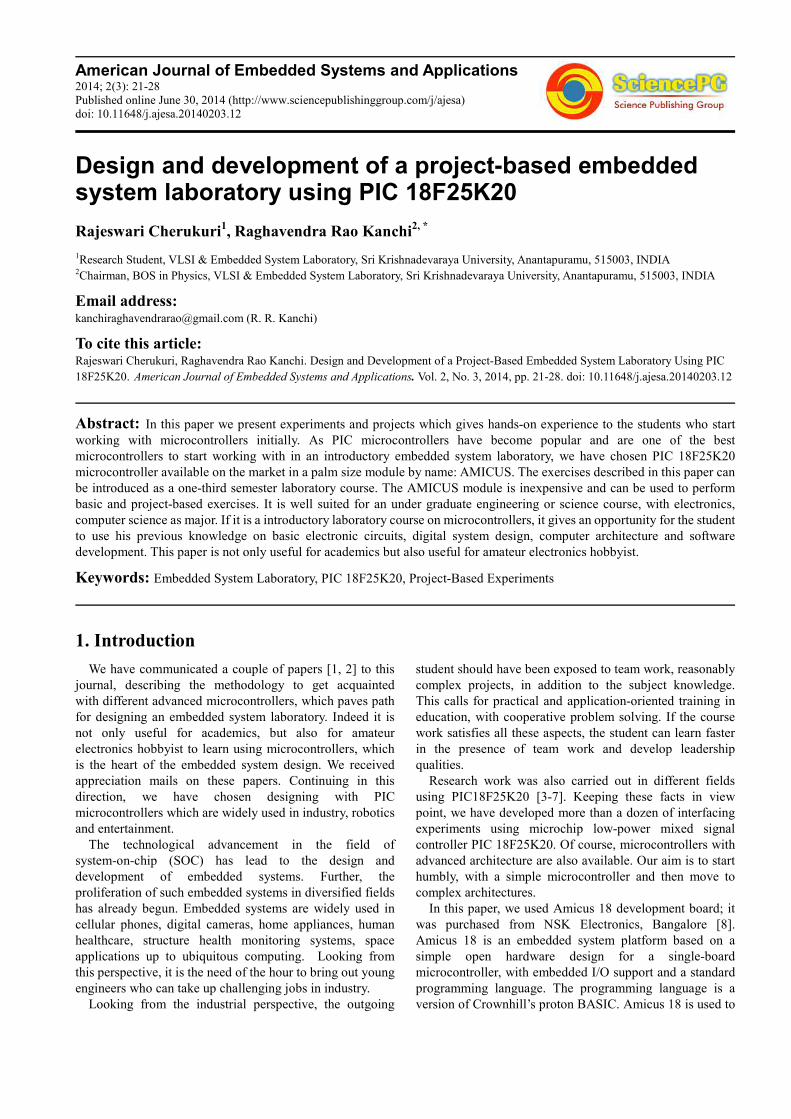
To get acquainted with GPIO pins, LEDs are connected to
port pins RB0 to RB7 of PORT B with current limiting
resistors (220Ω), mounted on a bread board. The program
is developed using proton BASIC .
The software is developed based on the following
algorithm:
Step 1. Start
Step 2. Create a variable to hold the state of PORT B.
Step 3. Make Port B output low.
Step 4. Transfer the variable value to Port B.
Step 5. Shift a bit left one position.
Step 6. Shift a bit right one positin.
Step 7. Do it forever.
Figure A1 shows the photograph of the experiment
24 Rajeswari Cherukuri and Raghavendra Rao Kanchi: Design and Development of a Project-Based Embedded System Laboratory Using PIC 18F25K20
Fig. A1. Amicus 18 interfaced with LEDs
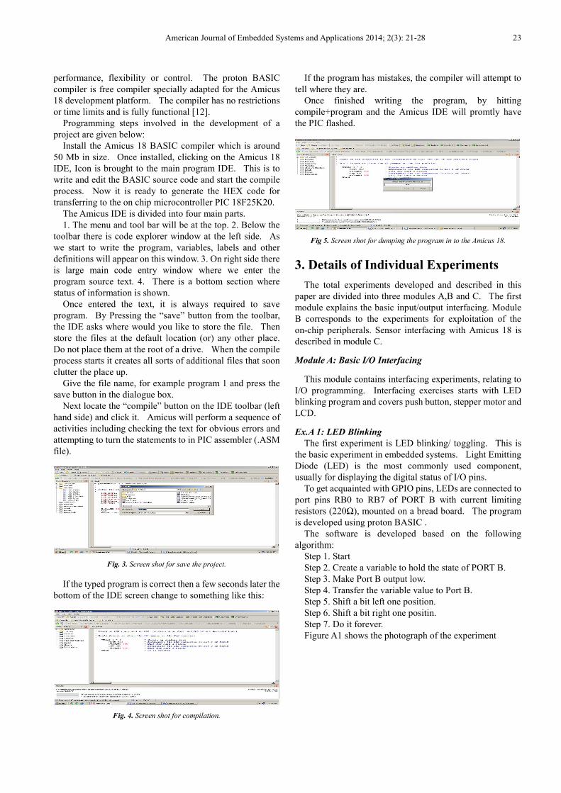
Ex. A 2: Push button interface
The main aim of the experiment is to debounce a
mechanical switch by software while counting the number
of times the button is pressed. The status of the pushbutton
after debouncing is observed using LED connected to RB0
while the push button is connected to RB1. All these
components are placed on the bread board and connected to
Amicus18 board as shown in figure A2.
The software is developed based on the following
algorithm:
Step 1. Start
Step 2. Define a variable to hold the switch pressing.
Step 3. Make Port B as output.
Step 4. Make the switch pin input
Step 5. Debounce the switch.
Step 6. Do it forever.
Figure A2 shows the photograph of the experiment
Fig. A2. Amicus 18 interfaced with push button
Ex .A 3: Seven segment Display
In this experiment RB0 to RB7 of PortB pins are used for
interfacing a seven segment display. Common anode type
seven segment display, current limiting resistors, bread
board and connecting wires are required to construct the
hardware.
The software is developed based on the following
algorithm
Step 1. Start
Step 2. Define a variable to hold the data to be displayed.
Step 3. Make Port B as output.
Step4. Display variable data on Port B.
Step5. Define delay
Step 6. Repeat forever
Figure A3 shows the photograph of the experiment
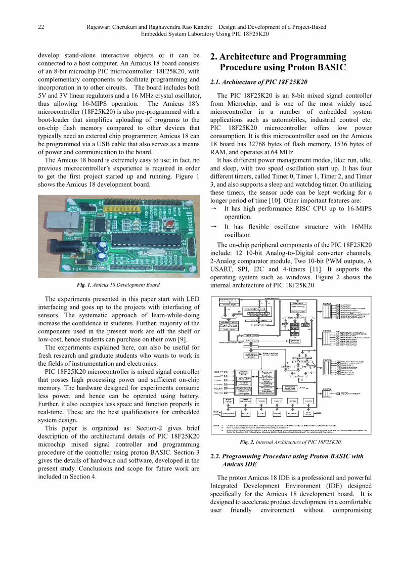
Fig. A3. Amicus 18 interfaced with seven segment, Hex value ‘8’ is
displayed on the seven segment display
Ex . A 4: Stepper Motor Interfacing Experiment
In this experiment the stepper motor is interfaced with
Amicus 18 board using Port B pins RB0 to RB 7. ULN
2003 is used for driving the motor. Because the controller
can’t give the sufficient current to output port to driven the
motor. Required components are stepper motor, IC ULN
2003, Connecting wires and bread board.
The stepper motor is rotated in steps continuously, by
developing the software basing on the following algorithm:
Step 1. Start
Step2. Initialize Port B as output port.
Step 3. Put 88H in B register.
Step 4. Call delay.
Step 5. Rotate B register right.
Step 6. Stop
Figure A4 shows the photograph of the experiment
Fig. A4. Amicus 18 interfaced with stepper motor
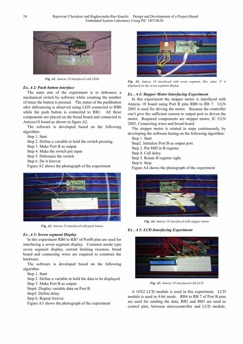
Ex . A 5: LCD Interfacing Experiment
Fig. A5. Amicus 18 interfaced with LCD
A 16X2 LCD module is used in this experiment. LCD
module is used in 4-bit mode. RB4 to RB 7 of Port B pins
are used for sending the data, RB2 and RB3 are used as
control pins, between microcontroller and LCD module.
American Journal of Embedded Systems and Applications 2014; 2(3): 21-28 25
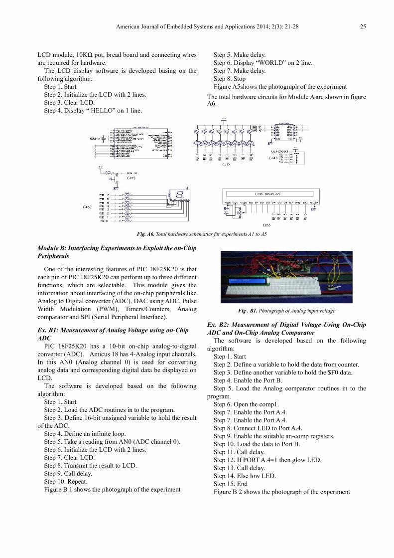
LCD module, 10KΩ pot, bread board and connecting wires
are required for hardware.
The LCD display software is developed basing on the
following algorithm:
Step 1. Start
Step 2. Initialize the LCD with 2 lines.
Step 3. Clear LCD.
Step 4. Display “ HELLO” on 1 line.
Step 5. Make delay.
Step 6. Display “WORLD” on 2 line.
Step 7. Make delay.
Step 8. Stop
Figure A5shows the photograph of the experiment
The total hardware circuits for Module A are shown in figure A6.
Fig. A6. Total hardware schematics for experiments A1 to A5
Module B: Interfacing Experiments to Exploit the on-Chip
Peripherals
One of the interesting features of PIC 18F25K20 is that
each pin of PIC 18F25K20 can perform up to three different
functions, which are selectable. This module gives the
information about interfacing of the on-chip peripherals like
Analog to Digital converter (ADC), DAC using ADC, Pulse
Width Modulation (PWM), Timers/Counters, Analog
comparator and SPI (Serial Peripheral Interface).
Ex. B1: Measurement of Analog Voltage using on-Chip
ADC
PIC 18F25K20 has a 10-bit on-chip analog-to-digital
converter (ADC). Amicus 18 has 4-Analog input channels.
In this AN0 (Analog channel 0) is used for converting
analog data and corresponding digital data be displayed on
LCD.
The software is developed based on the following
algorithm:
Step 1. Start
Step 2. Load the ADC routines in to the program.
Step 3. Define 16-bit unsigned variable to hold the result
of the ADC.
Step 4. Define an infinite loop.
Step 5. Take a reading from AN0 (ADC channel 0).
Step 6. Initialize the LCD with 2 lines.
Step 7. Clear LCD.
Step 8. Transmit the result to LCD.
Step 9. Call delay.
Step 10. Repeat.
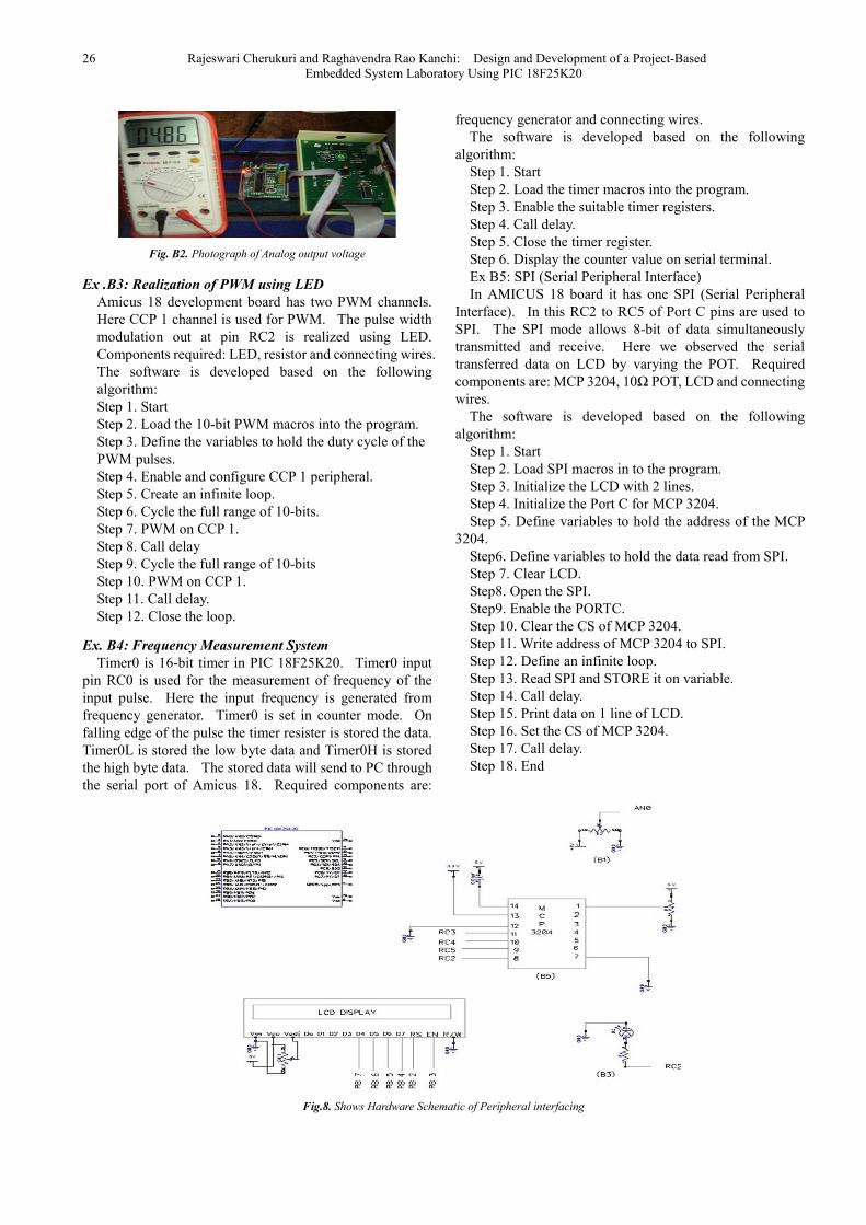
Figure B 1 shows the photograph of the experiment
Fig . B1. Photograph of Analog input voltage
Ex. B2: Measurement of Digital Voltage Using On-Chip
ADC and On-Chip Analog Comparator
The software is developed based on the following
algorithm:
Step 1. Start
Step 2. Define a variable to hold the data from counter.
Step 3. Define another variable to hold the $F0 data.
Step 4. Enable the Port B.
Step 5. Load the Analog comparator routines in to the
program.
Step 6. Open the comp1.
Step 7. Enable the Port A.4.
Step 7. Enable the Port A.4.
Step 8. Connect LED to Port A.4.
Step 9. Enable the suitable an-comp registers.
Step 10. Load the data to Port B.
Step 11. Call delay.
Step 12. If PORT A.4=1 then glow LED.
Step 13. Call delay.
Step 14. Else low LED.
Step 15. End
Figure B 2 shows the photograph of the experiment
26 Rajeswari Cherukuri and Raghavendra Rao Kanchi: Design and Development of a Project-Based Embedded System Laboratory Using PIC 18F25K20
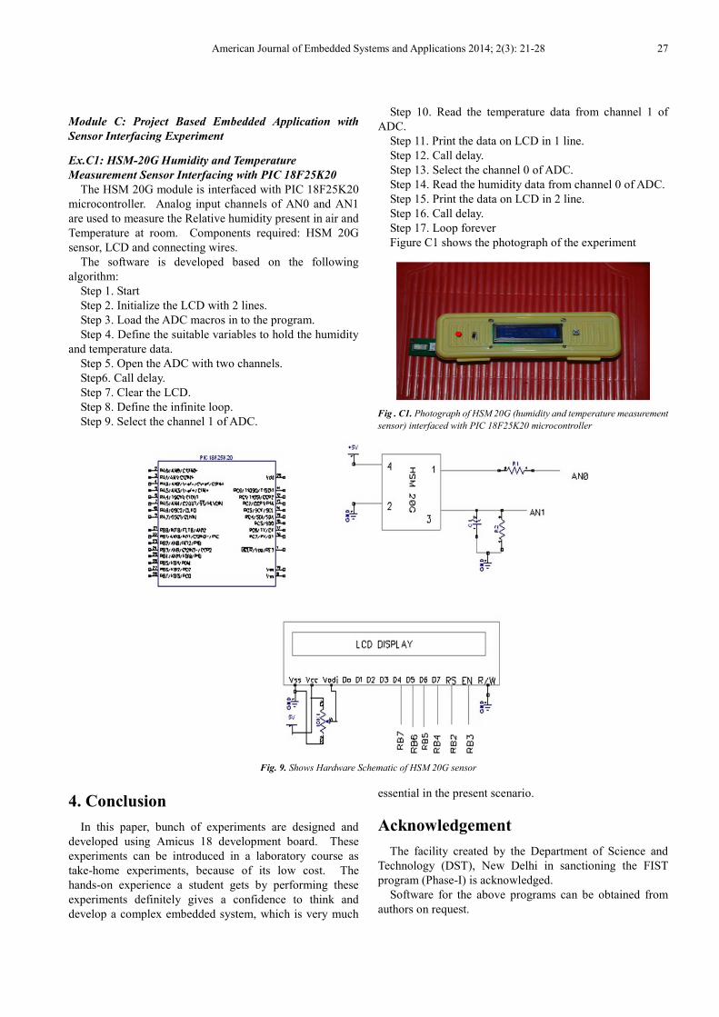
Fig. B2. Photograph of Analog output voltage
Ex .B3: Realization of PWM using LED
Amicus 18 development board has two PWM channels.
Here CCP 1 channel is used for PWM. The pulse width
modulation out at pin RC2 is realized using LED.
Components required: LED, resistor and connecting wires.
The software is developed based on the following
algorithm:
Step 1. Start
Step 2. Load the 10-bit PWM macros into the program.
Step 3. Define the variables to hold the duty cycle of the
PWM pulses.
Step 4. Enable and configure CCP 1 peripheral.
Step 5. Create an infinite loop.
Step 6. Cycle the full range of 10-bits.
Step 7. PWM on CCP 1.
Step 8. Call delay
Step 9. Cycle the full range of 10-bits
Step 10. PWM on CCP 1.
Step 11. Call delay.
Step 12. Close the loop.
Ex. B4: Frequency Measurement System
Timer0 is 16-bit timer in PIC 18F25K20. Timer0 input
pin RC0 is used for the measurement of frequency of the
input pulse. Here the input frequency is generated from
frequency generator. Timer0 is set in counter mode. On
falling edge of the pulse the timer resister is stored the data.
Timer0L is stored the low byte data and Timer0H is stored
the high byte data. The stored data will send to PC through
the serial port of Amicus 18. Required components are:
frequency generator and connecting wires.
The software is developed based on the following
algorithm:
Step 1. Start
Step 2. Load the timer macros into the program.
Step 3. Enable the suitable timer registers.
Step 4. Call delay.
Step 5. Close the timer register.
Step 6. Display the counter value on serial terminal.
Ex B5: SPI (Serial Peripheral Interface)
In AMICUS 18 board it has one SPI (Serial Peripheral
Interface). In this RC2 to RC5 of Port C pins are used to
SPI. The SPI mode allows 8-bit of data simultaneously
transmitted and receive. Here we observed the serial
transferred data on LCD by varying the POT. Required
components are: MCP 3204, 10Ω POT, LCD and connecting
wires.
The software is developed based on the following
algorithm:
Step 1. Start
Step 2. Load SPI macros in to the program.
Step 3. Initialize the LCD with 2 lines.
Step 4. Initialize the Port C for MCP 3204.
Step 5. Define variables to hold the address of the MCP
3204.
Step6. Define variables to hold the data read from SPI.
Step 7. Clear LCD.
Step8. Open the SPI.
Step9. Enable the PORTC.
Step 10. Clear the CS of MCP 3204.
Step 11. Write address of MCP 3204 to SPI.
Step 12. Define an infinite loop.
Step 13. Read SPI and STORE it on variable.
Step 14. Call delay.
Step 15. Print data on 1 line of LCD.
Step 16. Set the CS of MCP 3204.
Step 17. Call delay.
Step 18. End
Fig.8. Shows Hardware Schematic of Peripheral interfacing
American Journal of Embedded Systems and Applications 2014; 2(3): 21-28 27
Module C: Project Based Embedded Application with
Sensor Interfacing Experiment
Ex.C1: HSM-20G Humidity and Temperature
Measurement Sensor Interfacing with PIC 18F25K20
The HSM 20G module is interfaced with PIC 18F25K20
microcontroller. Analog input channels of AN0 and AN1
are used to measure the Relative humidity present in air and
Temperature at room. Components required: HSM 20G
sensor, LCD and connecting wires.
The software is developed based on the following
algorithm:
Step 1. Start
Step 2. Initialize the LCD with 2 lines.
Step 3. Load the ADC macros in to the program.
Step 4. Define the suitable variables to hold the humidity
and temperature data.
Step 5. Open the ADC with two channels.
Step6. Call delay.
Step 7. Clear the LCD.
Step 8. Define the infinite loop.
Step 9. Select the channel 1 of ADC.
Step 10. Read the temperature data from channel 1 of
ADC.
Step 11. Print the data on LCD in 1 line.
Step 12. Call delay.
Step 13. Select the channel 0 of ADC.
Step 14. Read the humidity data from channel 0 of ADC.
Step 15. Print the data on LCD in 2 line.
Step 16. Call delay.
Step 17. Loop forever
Figure C1 shows the photograph of the experiment
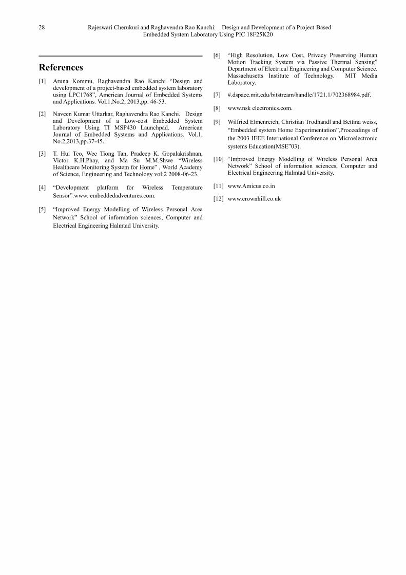
Fig . C1. Photograph of HSM 20G (humidity and temperature measurement
sensor) interfaced with PIC 18F25K20 microcontroller
Fig. 9. Shows Hardware Schematic of HSM 20G sensor
4. Conclusion
In this paper, bunch of experiments are designed and
developed using Amicus 18 development board. These
experiments can be introduced in a laboratory course as
take-home experiments, because of its low cost. The
hands-on experience a student gets by performing these
experiments definitely gives a confidence to think and
develop a complex embedded system, which is very much
essential in the present scenario.
Acknowledgement
The facility created by the Department of Science and
Technology (DST), New Delhi in sanctioning the FIST
program (Phase-I) is acknowledged.
Software for the above programs can be obtained from
authors on request.
28 Rajeswari Cherukuri and Raghavendra Rao Kanchi: Design and Development of a Project-Based Embedded System Laboratory Using PIC 18F25K20
References
[1] Aruna Kommu, Raghavendra Rao Kanchi “Design and development of a project-based embedded system laboratory using LPC1768”, American Journal of Embedded Systems and Applications. Vol.1,No.2, 2013,pp. 46-53.
[2] Naveen Kumar Uttarkar, Raghavendra Rao Kanchi. Design and Development of a Low-cost Embedded System Laboratory Using TI MSP430 Launchpad. American Journal of Embedded Systems and Applications. Vol.1, No.2,2013,pp.37-45.
[3] T. Hui Teo, Wee Tiong Tan, Pradeep K. Gopalakrishnan, Victor K.H.Phay, and Ma Su M.M.Shwe “Wireless Healthcare Monitoring System for Home” , World Academy of Science, Engineering and Technology vol:2 2008-06-23.
[4] “Development platform for Wireless Temperature
Sensor”.www. embeddedadventures.com.
[5] “Improved Energy Modelling of Wireless Personal Area
Network” School of information sciences, Computer and
Electrical Engineering Halmtad University.
[6] “High Resolution, Low Cost, Privacy Preserving Human Motion Tracking System via Passive Thermal Sensing” Department of Electrical Engineering and Computer Science. Massachusetts Institute of Technology. MIT Media Laboratory.
[7] #.dspace.mit.edu/bitstream/handle/1721.1/702368984.pdf.
[8] www.nsk electronics.com.
[9] Wilfried Elmenreich, Christian Trodhandl and Bettina weiss,
“Embedded system Home Experimentation”,Proceedings of
the 2003 IEEE International Conference on Microelectronic
systems Education(MSE”03).
[10] “Improved Energy Modelling of Wireless Personal Area Network” School of information sciences, Computer and Electrical Engineering Halmtad University.
[11] www.Amicus.co.in
[12] www.crownhill.co.uk