Embed Size (px)
Citation preview

Effective: November 16, 2000 DESIGN AND CONSTRUCTION STANDARDS 10-i
CITY OF BOULDERDESIGN AND CONSTRUCTION STANDARDS
CHAPTER 10STREETSCAPING STANDARDS
TABLE OF CONTENTS
Section Page
10.01 GENERAL..............................................................................................................................................................................1
(A) INTENT .................................................................................................................................................................................1(B) SCOPE...................................................................................................................................................................................1(C) REFERENCE STANDARDS ....................................................................................................................................................1(D) CITY APPROVAL REQUIRED................................................................................................................................................1(E) WATER CONSERVATION .....................................................................................................................................................1(F) PUBLIC LANDS OTHER THAN PUBLIC RIGHTS-OF-WAY ..................................................................................................1
10.02 SITE PREPARATION .........................................................................................................................................................1
(A) DESCRIPTION .......................................................................................................................................................................1(B) MATERIALS .........................................................................................................................................................................1(C) CONSTRUCTION REQUIREMENTS........................................................................................................................................2
10.03 PLANTING............................................................................................................................................................................5
(A) DESCRIPTION .......................................................................................................................................................................5(B) MATERIALS .........................................................................................................................................................................5(C) CONSTRUCTION REQUIREMENTS........................................................................................................................................7
10.04 SEEDING/SODDING........................................................................................................................................................11
(A) DESCRIPTION .....................................................................................................................................................................11(B) MATERIALS .......................................................................................................................................................................11(C) CONSTRUCTION REQUIREMENTS......................................................................................................................................16
10.05 UNDERGROUND IRRIGATION SYSTEM...................................................................................................................19
(A) DESCRIPTION .....................................................................................................................................................................19(B) MATERIALS .......................................................................................................................................................................19(C) CONSTRUCTION REQUIREMENTS......................................................................................................................................24
LIST OF TABLES
Number Page
Table 10-1: Topsoil Mechanical Analysis ............................................................................................................................... 10-2Table 10-2: Minimum Root Ball Sizes ....................................................................................................................................... 10-7Table 10-3: Wildflowers............................................................................................................................................................ 10-14Table 10-4: Grasses ................................................................................................................................................................... 10-15Table 10-5: Soil Amendment Mix Mechanical Analysis ...................................................................................................... 10-15


Effective: November 16, 2000 DESIGN AND CONSTRUCTION STANDARDS 10-1
10.01 General
(A) IntentThe Streetscaping Standards are intended to compliment the design standards specified in Chapter 3,“Streetscape Design and Tree Protection,” of these Standards, and provide minimum standards forthe construction and planting of streetscapes in public rights-of-way.
(B) ScopeThese Standards apply to streetscapes located, standing, or growing within or upon any City ofBoulder public right-of-way. The streetscape requirements of this chapter are in addition to those setforth in Chapter 3, “Streetscape Design and Tree Protection,” and applicable streetscape drawings inChapter 11, “Technical Drawings,” of these Standards and the B.R.C. 1981
(C) Reference StandardsWhere not specified in these Standards or the B.R.C. 1981, in order to protect the public health,safety, and welfare, the Director of Public Works in consultation with the Director of Parks andRecreation will specify the standards to be applied to the design and construction of streetscapes andthe planting of trees, and may refer to one or more of the references listed in the References Sectionof these Standards.
(D) City Approval RequiredAll work associated with the planting, maintenance, and removal of trees and landscaping materialslocated, standing, or growing within or upon any City of Boulder public right-of-way is subject toCity of Boulder approval or permit issuance as set forth in Chapter 8-5, “Work in the PublicRight-of-Way and Public Easements,” and Chapter 6-6, “Protection of Tree and Plants,” B.R.C.1981.
(E) Water ConservationAll landscaping shall be designed for maximum water efficiency, as specified in Section 9-3.3-3,“Landscape Design Standards,” B.R.C. 1981.
(F) Public Lands Other Than Public Rights-of-WayLandscaping construction activities on public lands other than public rights-of-way, such as parks,open space and greenway corridors, are exempt from the construction and planting requirements ofthese Standards. However, these Standards may be used as a basis for construction and plantingactivities on all public lands.
10.02 Site Preparation
(A) DescriptionSite preparation includes, without limitation, layout, tree protection, demolition, clearing, excavation,fill and backfill, topsoiling, and finish-grading.
(B) Materials
(1) Imported Fill: Imported fill for landscaping shall be clean, fertile, sandy loam soil that is

DESIGN AND CONSTRUCTION STANDARDS Effective: November 16, 200010-2
free from turf, lime, ashes, debris, noxious weeds, roots, stones over 4 inches in diameter,harmful chemicals, or other materials that are detrimental to plant growth. Fill shall have apH of 6.0 to 8.0, salt of less than 2 mmhos/cm, sodium absorption ratio of less than eight,and at least an 85 percent germination rate for narrow and broadleaf plants. Fill shall not behauled in a frozen, wet, or muddy condition.
(2) Topsoil
(a) Topsoil shall be fertile, friable, sandy loam topsoil. Topsoil shall be of any admixtureof subsoil or slag and shall be free of stones over 1 ½ inches in diameter, lumps,refuse, plants or their roots, sticks, noxious weeds, salts, soil sterilants or othermaterial that is detrimental to plant growth. If topsoil is delivered, it shall beobtained from a well-drained site that is free of flooding. Topsoil shall not bedelivered or used while in a frozen or muddy condition.
(b) Topsoil shall have an acidity range of pH 6.0 to 7.5 and contain not less than 5percent organic matter as determined by loss on ignition of moisture-free samplesdried at 100 degrees Centigrade. Topsoil shall have salt of less than 2 mmhos/cmand a sodium absorption ratio of less than eight.
(c) Topsoil shall meet the mechanical analysis outlined in Table 10-1, “TopsoilMechanical Analysis,” of these Standards:
Table 10-1: Topsoil Mechanical Analysis
Passing percent Retained percent
1-inch screen 100% 0 - 0%
½-inch screen 97 - 100% 0 - 3%
No. 100 mesh sieve 60 - 40% 40 - 60%
(d) Topsoil shall have at least an 85 percent germination rate for narrow and broadleafplants.
(C) Construction Requirements
(1) Layout
(a) The contractor is responsible for:
(i) Establishing and recording all necessary boundary points, lines, elevations,grades, access points, and benchmarks onsite for proper control, landscapeprotection, coordination with subcontractors, and execution of the work.
(ii) Verifying all furnished survey and topographic data, all points, lines, andelevations.
(iii) Notifying the Director of any discrepancies between information onapproved construction plans and actual site or field conditions ormeasurements and receive approval for required modification prior to

Effective: November 16, 2000 DESIGN AND CONSTRUCTION STANDARDS 10-3
continuing work.
(iv) Staking all cuts and fills on the sites as shown on the grading plan.
(b) Shoulders and toes of slopes shall be smoothly blended to the flat areas.
(c) No cut or fill is allowed within the dripline of existing trees without the priorapproval of the City.
(2) Clearing of Project Site: The contractor is responsible for:
(a) Removing from the site all trees and shrubs, brush and weed growth, stumps, androot systems designated on the approved construction plans for removal.
(i) All trees to be removed shall be marked with an “X” in blue permanentmarking and approved by the City prior to removal.
(ii) All other plant material not designated for removal shall be protected andmaintained.
(iii) Stripped-off brush and weed growth shall be hauled offsite. No burning ornesting of materials shall be permitted onsite.
(b) Maintaining adequate fire protection while clearing operations are underway.
(c) Replacing any existing sod damaged by construction operations. Replacement sodshall meet the standards of Section 10.04, “Seeding/Sodding,” of these Standards.
(d) If specifically required on the approved construction plans, scalping the top of soil,including grasses and roots, to a depth specified in the plans and stockpile onsite orremove as indicated.
(3) Excavation: The contractor is responsible for:
(a) Stripping, stockpiling, and replacing existing topsoil in areas of fill on the finishedgrade to at least 4 inches deep.
(b) Excavating so as to provide adequate drainage of the site at all times.
(c) Using hand methods of excavation within the dripline of trees.
(4) Fill and Backfill Operations: The contractor is responsible for the following:
(a) Obtaining the Director’s approval of the subgrade before commencing soilpreparation, topsoiling, finish grading or planting, and obtaining the Director’sapproval of the finish grade before commencing planting, mulching or othersubsequent operations. The following grading tolerances shall be applied:
(i) Tolerances shall not exceed 0.1 feet above or below desired subgradeelevations in planted areas, and no tolerance will be allowed on subgrades

DESIGN AND CONSTRUCTION STANDARDS Effective: November 16, 200010-4
prepared for paving or site improvements, or subgrades immediatelyadjacent to curbs or island pavements.
(ii) Settling of finish grade shall not exceed 0.1 feet.
(b) Completing clearing operations before beginning any filling or backfilling.
(c) If sufficient suitable fill or backfill material is not available on the project site, furnishing additional materials according to standards for hauled-in fill or topsoil, asrequired in these Standards.
(d) Placing fill and backfill in layers not to exceed 6 inches in compacted depth with thefollowing compaction standards:
(i) Each layer shall be compacted to the specified density. Landscaping fill andbackfill shall be compacted to no less than 80 percent and no more than 85percent density in areas to be planted.
(ii) Compaction shall not occur when soil is wet.
(e) Ensuring that filling and backfilling shall provide adequate site drainage at all times. Fill or backfill shall not be placed on wet ground.
(5) Finish Grading
(a) Work in this section shall consist of cutting, filling, shaping, and grading accordingto the lines, grades, elevations and cross sections on the approved landscaping plans.
(b) The contractor is responsible for the following:
(i) Completing all finish grading onsite. The top of the subgrade shall be thedepth below the finished grade as required for pavements, sod, walks,mulches and other site improvements.
(ii) Protecting the finish grade areas and regrading to correct any irregularitiescaused by hauling materials or by other operations over the finished grade.
(iii) Repairing any erosion or other damage resulting from weathering actionbefore final acceptance.
(c) Excavated and filled sections and adjacent transition areas shall be smooth, properlycompacted and free from irregular surface changes. The degree of finish gradingshall be that ordinarily obtained from either blade, grader, or scraper operations. Where finishing cannot be satisfactorily completed with power equipment, handmethods shall be used.
(d) Unless otherwise indicated, the subgrade shall be evenly sloped to provide drainageaway from site improvements or the centerline of medians. Swales shall be cut asshown on the plans, but shall not reduce the thickness of the topsoil specified.

Effective: November 16, 2000 DESIGN AND CONSTRUCTION STANDARDS 10-5
(e) Finish grading shall conform to the grade elevations shown on an approvedlandscaping plan and shall be free from debris and other materials that would bedetrimental to the subgrade. Settling of any finish grade shall not be more than 0.1feet, and if settling is greater, the contractor shall bring the grade to specifiedelevations.
10.03 Planting
(A) DescriptionPlanting includes, without limitation, the placement of live trees and shrubs, the placement ofmaterials to protect and enhance plant growth, and the methods applied in planting and maintaininglandscape plants.
(B) Materials
(1) Edger: Ryerson or approved equivalent steel edger, 1/8-inch by 4- inch steel with steelstakes, painted with rust-inhibiting black paint. The edger shall have a rolled or folded edgeor be capped with plastic safety-edged material.
(2) Filter Fabric: 30.1-mil DeWitt Weed Barrier or approved equivalent.
(3) Pesticides: Comply with the specifications of Section 6-10, “Pesticide Use,” B.R.C. 1981.
(4) Tree Wrapping Material: New, 4-inch wide, bituminous impregnated tape, corrugated orcrepe paper, brown in color, specifically manufactured for tree wrapping. Tree wrappingshall be fixed with pliable or nonbinding tape. No wire shall be used.
(5) Compost: Well-weathered and weed-free cow or sheep manure or other compostedmaterials. No mountain peat shall be used.
(6) Stakes: Green 8-foot steel tee posts with blade.
(a) Trees shall be secured to stakes using minimum 2 inch wide nylon and cotton blendwebbing with heat sealed ends, a tensile strength of 1000 pounds and brassgrommets for attachment of wire between strap and stake.
(b) Grommets shall be 1 ¼ - inch in diameter with a ½ -inch diameter e ye that is set atleast ½ -inch from end of strap.
(c) Wire shall be 12-gauge galvanized steel covered with a PVC sleeve.
(d) Straps shall be of sufficient length in relation to tree caliper so that grommets do nottouch trunk.
(e) A protective cap shall be secured to the top of all stakes.
(7) Mulch:

DESIGN AND CONSTRUCTION STANDARDS Effective: November 16, 200010-6
(a) Wood chip mulch shall be clean wood chips free of soil or man-made debrisshredded into coarse pieces ranging in size from 1 inches to 3 inches. All medianlandscape plantings shall be mulched with 4 to 6 inches of wood chips. 2 to 4 inchesof “Squeegee” (1/4-inch minus washed sand) may be substituted for wood mulchfor street median applications only.
(b) Rock mulch shall not be used in planting beds, except as a temporary mulch untilfull plant coverage is achieved, or as permanent mulch under shrubs. Rocks used inthe public right-of-way or adjacent to sidewalks must be 1 ½ to 3 inches in diameter. Gravel or cobblestone shall not be used as mulch.
(c) For medians and bikeways, landscape fabric shall not be used as a weed barrier.
(8) Plant Materials:
(a) All plants shall be “Colorado Grown,” “Colorado Fielded,” or “Northern Grown” asdescribed below, unless otherwise specified in these Standards, except for plants ofthe genus Juniperus.
(i) Colorado Grown: plants grown in Colorado nursery fields for the majorportion of their lives.
(ii) Colorado Fielded: plants shipped in or collected that have grown in Coloradonursery fields for at least two full growing seasons prior to delivery.
(iii) Northern Grown: plants grown in nurseries for at least two full growingseasons located in hardiness Zones 1 through 5, as shown on a UnitedStates Department of Agriculture map.
(b) All plants shall be of species identified under and allowed by these Standards andshall conform to the following:
(i) Selected to meet the goal of maximum water efficiency and zoned orgrouped according to their water requirements.
(ii) Individually identified on legible, weatherproof labels securely attached tothe plants. Labels shall be durable and shall remain legible for at least 60days from site delivery.
(iii) Labels shall include the correct genus, species, variety name and acceptedcommon name of the plant as well as the size or grade of stock.
(iv) Labels shall remain until after City inspection and then shall be removed bythe contractor.
(c) Tree selection and placement shall be in accordance with Section 3.03, “TreeSelection and Placement,” of the these Standards.
(d) Trees shall conform to and have the following characteristics:

Effective: November 16, 2000 DESIGN AND CONSTRUCTION STANDARDS 10-7
(i) A well-developed branch structure typical of the size and species with no“V” crotches, codominate stems, or included bark. The height of branchingshould bear a relationship typical of size and species so that the crown ofthe tree will be in balance as the tree grows.
(ii) Healthy buds, stems, and bark that are without mechanical, insect, ordisease injury.
(iii) Healthy, vigorous, and free from visual defects, mechanical injuries, plantdiseases, and all forms of insect infestation until final acceptance.
(iv) A well-branched and vigorous root system typical of size and species andfree from bent or kinked roots, roots girdling the trunk, and other defects.
(v) Root balls shall have a sufficient diameter for the fiberous and feeding rootsystem necessary to provide for full recovery of the tree following planting.Minimum root ball sizes shall meet the following specifications outlined inTable 10-2,
(vi)
Table 10-2: Minimum Root Ball Sizes
Caliper Minimum Root Ball Diameter Caliper Minimum Root Ball Diameter1 ½” 20” 3” 32”1 ¾” 22” 3 ½” 38”2” 24” 4” 42”
2 ½” 28” 4 ½” 48”
(e) All trees and shrubs shall be freshly dug at time of delivery, unless they arecontainer-grown. Plants other than bare root stock that have been heeled-in formore than 1 month or that exhibit roots outside the original ball shall not beaccepted. Bare root stock placed in cold storage for more than 2 months or thatexhibits new top growth will not be accepted.
(f) Moss rock shall be sandstone boulders with 75 percent or more exposed surfacecovered with lichens. Boulders shall have rounded natural edges and a character andshape consistent with native landscape rock settings. No split, bruised face, slab-type, layered, or slide rocks shall be used without prior approval and acceptance bythe .
(C) Construction Requirements
(1) Layout and Identification: The contractor shall use stakes, flags, or containerized plantsto locate all trees and shrubs according to an approved landscape plan.
(2) Schedule

DESIGN AND CONSTRUCTION STANDARDS Effective: November 16, 200010-8
(a) Nothing shall be planted between October 15 and March 1 without prior writtenapproval of the City. Stock, other than container-grown stock, shall not be plantedbetween June 1 and September 1 without prior written approval of the City. Bareroot stock shall not be planted after April 30 or if plants have begun to leaf out.
(b) Nothing shall be planted during freezing or excessively windy, hot, or wet weatheror when the ground conditions cannot be properly worked for digging, mixing,raking, or grading.
(c) Nothing shall be planted until the adjacent site improvements, pavements, irrigationinstallation and finish grading is completed. The contractor shall test the irrigationsystem in the presence of the Director. The irrigation system shall be in approved,operating condition prior to any planting.
(3) Plant Protection and Delivery
(a) The contractor shall protect all installed plant material from injury, excessive dryingor winds, improper ventilation, over watering, freezing, high temperatures, or anyother condition damaging to the plant until final acceptance. Any plants showingevidence of poor care or that are molded, mildewed, wilted, or dried-out shall berejected. Colored waxes or other materials that coat the aerial parts of plants, or theremoval of primary buds and/or shoots, including terminal buds and first orderleaders, of plants are not acceptable.
(b) Plant materials shall be planted on the day of delivery if possible. All plants notplanted on day of delivery shall be placed in a temporary nursery, kept moist, shadedand protected from sun and wind. If balled and burlapped plants are not planted onthe day of delivery, they shall be heeled-in immediately in the temporary nursery,kept moist and protected with damp soil, moss, or other acceptable material. Allplants shall be planted within 48 hours after delivery. Plants shall not be bound withwire or rope that may damage the bark or break branches. Plants shall be lifted andhandled from bottom of ball or container, and shall not be dropped or lifted by thetrunk, stem or foliage. Plants with balls that are loose, cracked, broken, man-madeor completely dry or plants with trunks loose in the ball before or during plantingoperations shall not be accepted and shall be removed from the site at contractor'sexpense. The root collar is not to be deeper than 4 inches below the top of the soilball.
(c) The contractor shall deliver all packaged landscape materials to the site in originalunopened containers bearing name, trade name, manufacturer, trademark, andconformance to State Law.
(d) Existing trees shall be protected per Section 3.05, “Tree Protection for ConstructionSites,” of these Standards.
(4) Excavation of Planting Pit
(a) All plant pits shall be centered on the plant location and excavated in a cylindricalshape with vertical sides and flat bottom. The depth of the plant pit shall bemeasured from the finished grade of the soil, not from the mulch. The base of all

Effective: November 16, 2000 DESIGN AND CONSTRUCTION STANDARDS 10-9
soil balls shall be placed on undisturbed soil.
(b) Trees: The diameter of all tree pits shall be at least two times the diameter of the ballor spread of the roots. Tree pits shall be excavated so that the top of the ball will be3 inches above finished grade when irrigated and 2 inches when not irrigated.
(c) Shrubs: The diameter of all shrub pits shall be at least two times diameter of the ballor spread of roots. Shrub pits shall be excavated so that the top of the ball will be 1inch above finish grade.
(d) Vines and Ground Covers: The diameter of all vine and ground cover pits shall betwo times the spread of roots. The planting pit shall be excavated so that the top ofthe ball is 1 inch above finish grade.
(e) All holes and pits shall be protected as specified in the General Conditions at all timeswhen work is not being carried on at the site of excavation.
(5) Planting and Staking for Plant Installation
(a) Plants shall be set in the center of the pit on the undisturbed subgrade. Immediatelyafter setting in the pit, all materials shall be completely removed from the ball andtrunk, including but not limited to plastic, metal, wire, wood, cardboard, paper,fiber, burlap, and twine. Container removal and plant handling shall minimize injuryto the plant, the root system, and the soil ball. If the root system of a containergrown plant has become container-bound, the roots shall be gently vertically cut ontwo sides of the root ball prior to planting.
(b) All plants shall be placed and kept plumb and straight as the pit is filled with backfill. Any plant that is not plumb prior to final acceptance shall be rejected.
(c) After placing plant in the pit, the hole around the plant root system shall be halfwaybackfilled and any large air pockets removed by hand with the blunt, handle end of ashovel or other such hand tool. If the ball is excessively dry, the contractor shallthen insert a deep watering device into the ball at a 45 degree angle every 12 inchesfor 1 minute. The pit shall then be lightly filled with backfill mix and compactedagain with the shovel. No mechanical compaction shall be allowed. The pit shallthen be watered by thoroughly saturating the backfill with water to a minimum depthof 3 feet. No watering shall be done prior to this time. Watering shall be repeatedonce when all free water has disappeared; this second watering shall not becompleted if the subgrade around the pit is already moist. After watering, thecontractor shall add the necessary soil to establish the finish grade level beforeadding specified mulch. The contractor shall remove all surplus soil and debris, andstake and guy trees immediately after planting.
(d) Unless otherwise specified, all areas designated for mass planting such as for groundcovers or vines shall be amended with 6 cubic yards per 1,000 square feet ofmanure compost. The contractor shall first prepare the subgrade by discing orrototilling the subgrade to a depth of 8 inches. No ripping or chiseling shall beallowed. After preparing the subgrade, the amendments shall be thoroughlyrototilled into the soil to a depth of 8 inches. The contractor shall remove any

DESIGN AND CONSTRUCTION STANDARDS Effective: November 16, 200010-10
rocks, debris or foreign matter in excess of 1 inch in length or diameter encounteredto an 8-inch depth.
(e) For all trees, the contractor shall drive stakes 3 feet vertically into firm soil outsidethe plant pit with blade on tree side. The contractor shall run a double strand ofwire through one grommet in the strap, wrap the strap around trunk at no more thanone-third the height of tree, and run wire through other grommet and back to stake. Strap and wire attachment between the stake and tree shall be adjusted so thatstraps are under just enough tension to avoid visible sag in lines. Rigid guying shallnot be accepted. Straps and wires shall be placed so as to be perpendicular to thetrunk. Stakes shall be parallel or slightly angled away from the trunk.
(f) The contractor shall place stakes according to tree height or caliper as follows:deciduous trees 2 inches and under - one stake oriented northwest; deciduous treeslarger than 2 inches but less than 3 inches and evergreen trees less than 5 feet inheight - two stakes oriented northwest and southeast; deciduous trees 3 inches andlarger and evergreen trees 5 feet and larger - three stakes with one orientednorthwest and the other two oriented 120 degrees in either direction formnorthwest. All deciduous trees shall have a sod-free base at least 3 feet in diameter. All evergreen trees shall have a sod free base extending to the dripline. This sodfree area shall be extended where necessary to include all stakes. The contractorshall return to the site and remove stakes between May 21 and June 7 the followingspring.
(g) The contractor shall remove all stakes and guy wires no more than one year fromthe date of tree installation.
(6) Spraying, Wrapping, Pruning, Watering and Mulching for Plant Installation
(a) All deciduous trees shall be wrapped by the contractor from November 1 - 15 of theyear in which they are planted. Specified tree wrap shall be cut in a continuous stripof sufficient length to wrap the tree. This wrapping shall begin at the ground linewith overlapping wraps of 1½ inches terminating above the lowest main branch ofthe tree. Final wrap shall be secured with tape in at least three places. Thecontractor shall return to the site and remove wrap from April 1 - 15 of thefollowing spring. The contractor shall notify the City at least 1 week prior to wrapremoval.
(b) After inspection, and with the approval of the City, the contractor shall prune plantsas necessary to remove only dead, injured, diseased, or crossing branches. All cutsshall be made just outside of the flare (branch collar) of the branch base. Allpruning shall be executed so as to preserve the natural form and character of theplant. The contractor shall return to the site between May 21 and June 7 thefollowing spring and prune all dead, diseased or injured branches from plants asspecified above. The contractor shall notify the City at least 1 week prior tocommencing pruning.
(c) After watering on the day of planting, and throughout the maintenance period, thecontractor shall ensure that plants are not over watered.
(d) Wood chip mulch shall be placed in all planting beds, shrub areas and the sod-free

Effective: November 16, 2000 DESIGN AND CONSTRUCTION STANDARDS 10-11
area of a 3-foot radius at the base of each tree. The mulch shall be spread carefullyand evenly to a depth of 4 inches. Shredded wood chip mulch shall be wateredthoroughly two times to aid in matting the mulch in place. The mulched areas shallbe graded so that the top of the mulch will be flush with the top of the curb,sidewalk, edging or sod.
(e) Rock mulch shall be placed evenly to a minimum depth of 2 inches.
(f) The contractor shall be responsible for damage to any underground utility, irrigationline, paving, adjacent structures or other improvements. In the event a pipe, line,rock formation, or other obstruction interferes with a plant location, the contractorshall notify the Director to receive approval for a new plant location.
(7) Moss Rock Installation Procedure
(a) The contractor shall notify the Director prior to moss rock placement work in orderto direct the contractor in a continuous operation of placing the rock with thedesignated quantities. The contractor shall provide manpower and equipment toplace rock in 1 day and shall haul excess rock away from site.
(b) The contractor shall install rock boulders according to the layout and configurationof the rock work as shown on the plans. Moss rock shall be set on a compactedbase (to 90 percent Proctor Density within 2 percent optimum moisture content). Rockwork joints shall be made tight by butting natural faces together in place. Soilgrades shall be adjusted to stabilize rocks in position and regraded in place toestablish the placement of each rock so that they blend into adjacent terrain. Rocksare to be placed by terracing or stepped layers to achieve a naturalized effect. Finishgrades shall be re-established as necessary.
10.04 Seeding/Sodding
(A) Description
(1) Seeding/sodding includes, without limitation, the planting and installation of grasses,preparation of soils and grading, and the methods to be applied in planting and maintaininggrasses.
(2) Medians less than 12 feet wide shall be landscaped with materials other than irrigatedturfgrass.
(B) Materials
(1) Fertilizer: Specified fertilizer shall be supplied in the original supplier's containers with labeland order form showing composition and quantity. Fertilizer shall be intact, free-flowing,dry and in quantity, as specified for sodded or seeded areas, as shown on the plans. Fertilizer for sod and seeding soil preparation shall be a compound equivalent to 0-46-0applied at the rate of 10 pounds per 1,000 square feet.
(2) Bluegrass: Bluegrass shall be Colorado-grown, 100 percent certified Kentucky Bluegrass,

DESIGN AND CONSTRUCTION STANDARDS Effective: November 16, 200010-12
of three improved bluegrass varieties complying with applicable Colorado and Federalregulations. Newport, Park, Delta and Common Kentucky Bluegrass are not acceptablevarieties for the sod mixture. The sod shall have a vigorous and healthy root system and topgrowth and shall have been regularly fertilized, watered, mowed, sprayed and shall be freefrom objectionable weeds and/or grasses. Sod strip shall have from 5/8 inch minimum to 1inch maximum thickness of soil adhering to root system, cut into strips 18-inch maximumwidth by 4 feet minimum length. Sod that has dried out, or sod with adhering soil thatbreaks, tears or crumbles away will not be accepted. Sod cut for more than 24 hours shallnot be accepted. Sod rolls shall be kept moist, protected from sun, heat or wind in transportand after delivery. Prior to cutting, the sod shall be evenly mowed for a blade length of atleast 1 inch but not more than 2 inches.
(3) Turf-type Tall Fescue: Turf-type tall fescue seed or sod shall be purchased from areputable seed dealer, complying with requirements specified. Seed mixture shall be of atleast three varieties (a maximum of five) of dwarf type tall fescue (i.e., Monarch, El Dorado,Rebel Jr., Crew Cut, SR 8200, or other approved varieties).
(a) PLS shall not be less than 88 percent.
(b) Specified PLS shall be calculated as shown in Section (5)
(4) Buffalo Grass: Buffalo grass shall be either seed, plugs, or sod.
(a) Buffalo grass seed shall be purchased from a reputable seed dealer, complying withthe requirements specified. Seed mixture shall be “Texoka” or “Sharp's Improved”or approved equivalent.
(i) PLS shall not be less than 75 percent.
(ii) Specified PLS shall be calculated as shown in Subsection (B)(5).
(b) Buffalo grass plugs or sod shall be 100 percent certified turf-forming variety 609, orapproved equivalent. Buffalo grass imported from states south of Colorado may beapproved due to the difficulty in establishing sod in the front range climate.
(i) All sod shall be healthy, in vigorous condition, of natural green color, free ofdisease and harmful insects. The sod shall be laid within 48 hours ofharvest.
(ii) Plugs shall be cut from sod as described in this Section. Nursery grownplugs are acceptable with prior approval by the Director.
(c) If sod is to be used for medians larger than 12 feet wide, Buffalo grass is preferred.
(5) Native Seed: Native grasses and wildflowers for median plantings are listed in tables 10-3and 10-4. Native grass seed shall be purchased from a reputable seed dealer, complying withrequirements specified. Seed mixture shall be “Foothills” mix as provided by ArkansasValley Seed Company (303.320.7500), or approved equivalent.
(a) PLS shall not be less than 80 percent (average for the seed mix).

Effective: November 16, 2000 DESIGN AND CONSTRUCTION STANDARDS 10-13
(b) Quantity of bulk seed required to provide the specified PLS shall be calculated frompurity and germination percentage rates listed on the lot tag of seed actuallypurchased, using the following two formulas:
Purity Percentage x Germination Percentage = PLS Percentage
lbs. PLS specified per 1000 square feet = Bulk lbs. required per PLS percentage 1000 square feet

DESIGN AND CONSTRUCTION STANDARDS Effective: November 16, 200010-14
Table 10-3: Wildflowers
Common Name Latin Name
Blanket flower Gaillardia aristata
Blue flax Adenolinum (Linum) lewisiiBroom snakeweed Gutierrezia sarothrae
Bush sunflower Helianthus pumilus
Fringed sage Artemisia frigida
Greenleaf penstemon (blue mist) Penstemon virens
Nelson's larkspur Delphinium nelsonii
One-sided penstemon Penstemon secundiflorus
Prairie clover Dalea purpurea
Prairie coneflower Ratibida columnifera
Prairie sage (Sagewort) Artemisia ludoviciana
Prickly pear cactus Opuntia macrorhiza (compressa)
Rocky Mountain beeplant Cleome serrulata
Scarlet globe mallow Sphaeralcea coccinea
Spiderwort Tradescantia occidentalis
Spiny goldenweed Machaeranthera pinnatifida
Spotted gayfeather (Dotted gayfeather) Liatris punctata
Sulphur flower Eriogonum umbellatum
Western wallflower Erysimum asperum
White evening primrose Oenothera caespitosa
White yarrow (Woolly yarrow) Achillea lanulosa
Wild bergamot (Horsemint or Beebalm) Monarda fistulosa
Wild verbena Glandularia (Verbena) bipinnatifida
Yellow stemless evening primrose Oenothera howardii (brachycarpa)
Effective: November 16, 2000 DESIGN AND CONSTRUCTION STANDARDS 10-15
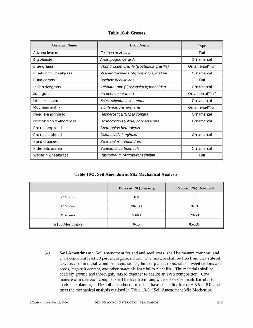
Table 10-4: Grasses
Common Name Latin Name Type
Arizona fescue Festuca arizonica Turf
Big bluestem Andropogon gerardii Ornamental
Blue grama Chondrosum gracile (Bouteloua gracilis) Ornamental/Turf
Bluebunch wheatgrass Pseudoroegneria (Agropyron) spicatum Ornamental
Buffalograss Buchloe dactyloides Turf
Indian ricegrass Achnatherum (Orzyopsis) hymenoides Ornamental
Junegrass Koeleria macrantha Ornamental/Turf
Little bluestem Schizachyrium scoparium Ornamental
Mountain muhly Muhlenbergia montana Ornamental/Turf
Needle-and-thread Hesperostipa (Stipa) comata Ornamental
New Mexico feathergrass Hesperostipa (Stipa) neomexicana Ornamental
Prairie dropseed Sporobolus heterolepis
Prairie sandreed Calamovilfa longifolia Ornamental
Sand dropseed Sporobolus cryptandrus
Side-oats grama Bouteloua curtipendula Ornamental
Western wheatgrass Pascopyrum (Agropyron) smithii Turf
Table 10-5: Soil Amendment Mix Mechanical Analysis
Percent (%) Passing Percent (%) Retained
2" Screen 100 0
1" Screen 90-100 0-10
½ " Screen 50-80 20-50
#100 Mesh Sieve 0-15 85-100
(4) Soil Amendment: Soil amendment for sod and seed areas, shall be manure compost, andshall contain at least 50 percent organic matter. The mixture shall be free from clay subsoil,sawdust, commercial wood products, stones, lumps, plants, roots, sticks, weed stolons andseeds, high salt content, and other materials harmful to plant life. The materials shall becoarsely ground and thoroughly mixed together to ensure an even composition. Cowmanure or mushroom compost shall be free from lumps, debris or chemicals harmful tolandscape plantings. The soil amendment mix shall have an acidity from pH 5.5 to 8.0, andmeet the mechanical analysis outlined in Table 10-3, “Soil Amendment Mix Mechanical

DESIGN AND CONSTRUCTION STANDARDS Effective: November 16, 200010-16
Analysis,” of these Standards.
(5) Erosion Control Netting: Jute mesh erosion control netting or approved equivalent shall beused.
(C) Construction Requirements
(1) Subgrade and Soil Preparation
(a) The contractor shall lay out and stake the boundary of all areas to be sodded,seeded, or plugged prior to commencing any work. After Director approval offinish grades, the contractor shall prepare the subgrade of all seeded or sodded areasby discing or rototilling the soil to a depth of 6 inches. No ripping or chiseling shallbe allowed. No rototilling or discing is to be done within the protection area ofexisting trees. After the subgrade has been completed, soil preparation shall beginby spreading the soil amendment evenly within the seeding or sodding limits at therate of 3 cubic yards per 1,000 square feet. If topsoil is used as the subgrade forsod or seed, soil amendment will not be required. Soil amendment is not required inareas to be seeded with native grasses.
(b) For sod, 0-46-0 fertilizer shall then be spread uniformly over the entire area at therates as specified for soil preparation. The area shall again be disced or rototilled atright angles to the first tillage, then formed by rolling to provide a proper seed bed orsodding surface. The sod or seed bed shall be totally free from rock, debris,vegetable matter, noxious weeds or clay clods over ½ inch diameter, prior to anysodding or seeding operations.
(2) Finish and Fine Grading
(a) Positive Surface Drainage: The contractor shall finish and fine-grade the projectarea to establish an even and well-matched grade over the entire surface. Positivesurface drainage shall be assured, and there shall be no depressions, subsequentsettling or irregularities in the finished grade.
(b) Transitional Areas: At any transitional point or line where one plane intersectsanother, such as from a sloping area or berm to a level area, a smooth and gentletransition shall be made. There shall be no abrupt changes in grade. There shall alsobe a smooth transition between existing turf and the new sod. The grade elevationsof the two areas shall be matching.
(3) Schedule: All seeding shall be scheduled between March 1 and October 15 unless priorwritten approval from the Director has been obtained.
(a) No sodding and seeding shall take place during inclement weather.
(b) No sodding and seeding work shall commence until the adjacent site improvements,pavements, irrigation installation and finish grading is completed. The irrigationsystem shall have been tested and be in operating order prior to any seeding orsodding.

Effective: November 16, 2000 DESIGN AND CONSTRUCTION STANDARDS 10-17
(c) The contractor shall barricade sodded area immediately after sod installation asspecified on the approved construction plans or in these Standards. The barricadeshall include the following:
(i) Standard construction lath at 5 foot intervals connected with three tiers ofcolored plastic flagging.
(ii) “KEEP OFF THE SOD” signs attached to the barricading every 25 feet.
(4) Seeding
(a) Following approval of the seed bed by the Director, seeding shall be done with aBrillion drill or approved mechanical seeder. Seed shall be evenly distributed on astill day into a slightly moist seed bed. Seed shall be drilled 1/8 inch into theprepared seed bed. If the slope is too steep to drill, seed shall be broadcast at doublethe application rate and covered with 1/8 inch of soil with a harrow or hand rake forsmall areas. The seeding shall be done in two separate applications crossing the areaat right angles to guarantee proper coverage. Drill seed across slopes rather than upand down, following the contour to reduce erosion.
(i) Native grasses shall be seeded at a rate of 20 pounds PLS/acre when drilledand 35 pounds PLS/acre when broadcast.
(ii) Buffalo grass shall be seeded at a rate of 3 pounds PLS/1000 square feetwhen drilled and 5 pounds PLS/1000 square feet. when broadcast.
(iii) Turf type tall fescue shall be seeded at a rate of 6 pounds/1000 square feetwhen drilled and 9 pounds/1000 square feet when broadcast.
(b) After seeding operations have been completed, the entire seeded area shall behydromulched with “Conwed 2000" or approved equal hydro mulch material. Thehydro mulch shall be applied by using mechanical hydromulcher, evenly distributedon a still day. The hydro mulch material shall be applied at the rates recommendedby the manufacturer. Within 12 hours after seeding, the sprinkler system shall beactivated to moisten seeded areas to a depth of 1 inch. All seeded areas shall be keptso moistened by frequent light watering until final acceptance of the project or asrequired by City Land Use Regulations, and such watering shall be the responsibilityof the contractor.
(c) Protect seeded slopes (greater than 2.5 horizontal to one vertical) with erosioncontrol netting or other methods acceptable to the Director. Cover netting withstraw or other acceptable mulch.
(5) Bluegrass Sodding
(a) Sod shall be laid on a firm, premoistened bed with tight joints so that no voids occurunder or between strips. All end joints shall be staggered and the sod roll lengthshall run perpendicular to all slope fall lines. Sod shall be tamped, rolled, and

DESIGN AND CONSTRUCTION STANDARDS Effective: November 16, 200010-18
watered immediately after sodding operations are completed.
(b) No sod shall be installed within a radius of 3 feet around any tree within the projectlimits. Shredded wood chips shall be installed to a 3 inch depth in this 3 foot area. All rolls terminating at the project limits shall be cut in a straight line unlessotherwise specified and the exposed edge covered with topsoil. All sod installedaround planting beds shall be cut to conform to the shape of the bed as shown onplan or laid out onsite. Sod shall be laid flush with paving, curbs and irrigation headsand 1 inch below the top edge of steel edging.
(c) In the event that sod dries or shrinks, a mixture of screened topsoil and specifiedbluegrass seed shall be brushed into the cracks and tamped flush. Excessivelyshrunk sod (over 3/4 inch shrinkage) shall be replaced with new sod. Any sod laidon slopes steeper than 3:1 (33 percent) shall be laid at a 90 degree angle to the slopeand held in place with two wooden dowels per sod piece.
(d) The contractor shall activate the sprinkler system to water sod immediately aftereach section of sod is laid. The contractor shall operate the sprinkler to soak all sodand the underlying soil to a depth of 2 inches and maintain this moisture level untilfinal acceptance. The contractor shall water the sod in the early morning and lateafternoon for the duration of this period.
(6) Buffalo Grass Sod
(a) Prior to sodding, the site should be lightly irrigated to alleviate “sod-wicking” anddesiccation. The sod shall be laid by staggering joints with all edges touching. Installation shall be performed between April 1 to August 31. Immediately followingthe laying of the sod, the sod should be rolled with a roller, weighing at least 150pounds, heavy enough to imprint the sod into the soil.
(b) The contractor shall irrigate immediately after any sod installation, so that the sodand underlying soil is completely wetted to a depth of 4 to 6 inches (saturated). Subsequent irrigation shall be applied as necessary as determined by daily inspectionof the sod panels. Daily inspection should consist of manually raising several sodpanels and testing the level of moistness in the soil by pinching the soil together. Ifthe soil remains 'pinched' together, and is moist, and the panel's sod pad is alsomoist, then the sod does not require watering that day. If the soil, after beingpinched, falls apart, the sod shall be irrigated to retain the required moisture level. The sod soil pad and underlying soil should be moist at all times.
(c) Rainfall received during the establishment period may reduce the irrigation required. If temperatures exceed 95 degrees for periods of several days, the sod may have tobe inspected more frequently and additional daily irrigation cycles may be required. If the soil that has been sodded is extremely hard, or compacted, and not easilysaturated, or dries out quickly, the sod and soil shall be kept consistently moist thefirst ten days.
(d) Normal establishment should display the following characteristics. Within 48 hoursof installation the sod should turn a straw color, which is called a dormant stage,although the roots would continue to grow while the top growth is dormant. Within5 to 7 days feeder roots should begin appearing. Within 14 to 21 days new green

Effective: November 16, 2000 DESIGN AND CONSTRUCTION STANDARDS 10-19
top growth should be seen and the sod should be firmly rooted. Once this occurs,daily manual inspections would no longer be required. Sod should then be watered1½ inches per week for 2 to three months, to prevent drought stress, until deeperrooting takes place.
(e) The contractor is to thoroughly discuss required installation, establishment and post-establishment methods, irrigation, and maintenance requirements with the sodsupplier (specifically for sod maintenance - weed control/removal, i.e., whatchemical can safely be used, etc.).
(7) Buffalo Grass Plugs
(a) Plugs shall be planted on 12 inch centers with a requirement of at least nine (9)plugs per square yard of ground. Plugging machinery must convert 16 x 24 inchsod panels into plugs and plant in one operation. Each 16 x 24 inch sod panel yields24 4 inch square plugs, with a total of 81 plugs cut from a yard of sod. At least 80percent of the plugs shall be a 4 inch square plug (4 x 4 inches); minimumacceptable size for the remainder of the plugs is 2 x 4 inches, nor maximum size anylarger than 4 inch x 4 inch. Coordinate equipment passes to maintain parallel, evenlyspaced rows. Immediately following plugging, the plugs should be rolled with aroller, weighing at least 150 pounds, heavy enough to imprint the plugs into the soil.
(b) All plugs shall be planted within 48 hours of harvest of the sod. All plugs shall behealthy, in vigorous condition, of natural green color, free of disease and harmfulinsects. Water after any portion of the plugging is complete, within 4 hours ofplanting, so that the plugs are completely wetted and the underlying soil is wetted toa depth of 4 to 6 inches.
(c) All buffalo grass sod establishment, irrigation, and maintenance requirements shallapply to plugs. Plugs will require more frequent manual inspection and morefrequent watering. After the initial establishment period, plugs should be watered 1inches per week until desired coverage is achieved.
10.05 Underground Irrigation System
(A) Description
Underground irrigation includes, without limitation, installing a complete underground irrigationsystem consisting of irrigation pipelines, sprinklers, valves, and controllers as part of any landscapingproject.
(B) Materials
(1) Sprinkler System Components: All sprinkler system components shall be those of themanufacturers specified in these Standards, or be an approved equivalent, and shall beinstalled in accordance with these Standards.
(2) Sprinkler Heads: Pop-up rotary impact or stream spray sprinklers shall be used to watersod and shrub areas, using full and part circle heads as specified on any approved landscapeplans. Requirements for the sprinklers include the following:

DESIGN AND CONSTRUCTION STANDARDS Effective: November 16, 200010-20
(a) Sprinklers shall provide coverage as specified on any approved landscape plans, plusor minus 5 percent of the flow rate and 2 ½ feet within the design radius during alow wind situation.
(b) Sprinkler heads shall meet the following specifications:
(i) Minimum pop-up height of 2-5/16 inches with heavy retract spring;
(ii) Part circle sprinklers shall be adjustable for any arc between 20 and 340degrees;
(iii) Have built-in check valves in the head to control low head drainage andreduce air compression in lines. The check valve shall be serviceable fromthe top of the head without requiring excavation and removal of the headfrom the riser.
(c) Sprinklers shall be vandal resistant, and shall have vandal-resistant cover screws orno exposed screws in the cover.
(d) Sprinklers shall be tamper resistant to prevent changing the direction of throws bymeans of locking friction collars, gear drives, and limited access features.
(e) Sprinklers shall have a drive mechanism that will ensure proper and even rotationand coverage on 4:1 slopes.
(f) Sprinklers shall have rubber covers or similar protective devices.
(3) Bubblers: Requirements for bubbler heads shall include the following items.
(a) Heads shall operate properly between 10 psi and 80 psi;
(b) Heads shall have a molded plastic body with a ½ inch female pipe thread;
(c) Heads shall have a nozzle flow adjusting screw, providing fully open to completelyclosed positions;
(d) Heads shall have a plastic basket screen to protect nozzles from clogging.
(4) Automatic Control Valves
(a) Automatic electric remote control valves shall be slow acting diaphragm-typeelectric solenoid valves. Solenoids shall be two-watt running, current 24 volt AC,50/60 cycle operation. The valve shall be slow opening and closing by means of a“shunt” resistor to avoid damage from surge pressures. Valve flow range shall be 1to 200 gallons per minute depending on size with a pressure range of 10 to 200 PSI.
(b) All valve bodies and bonnets shall be constructed of heavy case bronze withaccurately machined valve seat surfaces and internal parts. Inlet part of diaphragmchamber shall have a removable screen for easy cleaning, accessible without

Effective: November 16, 2000 DESIGN AND CONSTRUCTION STANDARDS 10-21
removing bonnet from valve body. Valve bonnets shall be equipped with a slottedplug or bleed screw for manual operation of valves at any time without energizingthe solenoid, and a manual flow control stem.
(5) Isolation Gate Valves: Isolation gate valves for installation on main lines shall be of brassconstruction, designed for 200 psi working pressures, and have solid disc, non-rising stemswith a heel and screwed ends. Gate valves 3 inches or larger shall be brass or iron AWWAgate valves with rubber gaskets or mechanical joints.
(6) Quick-Coupling Valves: Quick-coupling valves installed in main lines shall be of a castbrass body construction, and have a self-closing and locking protective cover. The throatshall incorporate a single keyway with positions for regulation of water flow, with a flowrange of 10 to 70 gallons per minute and a pressure range of 5 to 125 psi. Replaceable sealsshall be provided at the valve seat and throat, and the internal parts shall be removable forservice. Installation on a main line in shall include a 10-inch circular locking valve box overthe coupler body. Size shall be 1 inch. Quick-coupling valve keys shall have 1 inch male toppipe threads. Swivel hose ells shall be 1 inch N.P.T. x 3/4 inch hose thread.
(7) Manual Drain Valves: The system shall be equipped with 3/4 inch manual globe drainvalves at all low points on main lines. Valves shall be of bronze construction with threadedconnections, cross handles, and operating keys. Install valves in a locking valve box. Anglevalves will not be accepted.
(8) Y-Strainers: Y-Strainers for installation on main line shall be bronze “Y” type strainers witha screen mesh.
(9) Wire Connectors: All wire connections at electric control valves and all splices of wire inthe field shall be made using “snap-tits,” or an approved equivalent, wire connectors. Significant requirements for connectors include the following items:
(a) Connectors shall be rated at 600 volts for PVC insulated copper wire, UnderwritersLaboratory listed, and water-resistant.
(b) Connectors shall consist of a PVC base socket, sealing plug, and wire crimpingsleeve and shall provide a permanent waterproof joint by using a sealer for jointmakeup.
(10) Controllers
(a) Automatic sprinkler controllers shall be completely automatic in operation, and shallelectrically start all sprinkler cycles and time the individual stations. Controllers shallhave standard 117 volt power inputs, 24.0 volt, 60 cycle outputs with separateindependent timing stations, 14 day programming, and be capable of automaticallystarting a watering cycle at the beginning of any hour for 23 hours per day. Eachstation shall have an “OFF” switch for “0" time and individual incremental timingcontrol for 0 to 60 minute station timing. Each station shall have an “ON-Repeat”switch for eliminating one or more stations from initiating a repeat cycle on any orall stations after the normal watering cycle has been completed. A 14 day clockshall be provided for maximum programming versatility and any timer pins shall beof the captive type to prevent loss. It shall be possible to operate controller manually

DESIGN AND CONSTRUCTION STANDARDS Effective: November 16, 200010-22
and to select and operate manually any station. All controls shall be capable of beingmanipulated at any time in any sequence without damage to controller. Thecontroller shall have the ability for dual programming and shall have soil moisturesensing equipment.
(b) Soil moisture sensing equipment shall have an adjustable control module with anoverride function, and at least two in-ground sensors/tensiometers. Sensors mustbuffer salinity, and have the ability to withstand winter conditions without removal.
(c) A reset circuit breaker shall protect each controller from damage due to excessivecurrent. A master “ON-OFF” switch shall provide for turning controller “OFF”during rainy weather, while allowing day and hour clocks to continue in operation. The controller shall have as standard built-in features an electrical circuit to operate amaster valve and moisture sensor circuit to allow operation of controllers inconjunction with a moisture sensing device. Install valve output surge protectionarresters for control wiring and common.
(d) All wiring to and from controllers shall be through color-coded plugs and sockets. Controller cabinets shall be locking, weatherproof type, constructed of heavy gaugesteel with corrosion resistant enamel finish inside and out.
(e) Controllers shall conform to NEC Class 2 requirements of 24 volt valves. Controllers shall be for wall or pedestal mounting.
(11) Valve Boxes: Valve boxes shall be sized to provide maintenance access to all valve andcontroller component. The underside of all control valve boxes shall be clearly marked toindicate controller numbers and valve numbers.
(12) Pipe
(a) Main Line Pipes:
(i) Main pressure line pipe shall be NSF approved virgin polyvinyl chloridepipe. Pipe shall be suitable for use at maximum hydrostatic workingpressures of 200 PSI. Pipe shall be made from clean, virgin, NSFapproved, type 1, grade 1 PVC, conforming to Astin Resin specificationD1784-60 and project standard D2241 for PVC 1120 SDR 26 or SDR 21. PVC pipe is to be belled end and solvent weld. Solvent cement and primershall be of the type prescribed by the manufacturer.
(ii) Gasket pipe and fittings shall be used for main lines 3 inches or larger. Gasketed pipe shall be of the type prescribed by the manufacturer. Noinsert gaskets or insert gasket fittings shall be accepted. Thrust blocks shallbe provided in accordance with pipe manufacturer's recommendations.
(b) Marking and Declaration of Compliance: Pipe marking shall show the size, series,identification, and manufacturer's trade name at intervals of not more than 20 feet. Pipe shall include the seal of approval of the National Sanitation Foundation spacedat intervals required by NSF regulations.
(c) PVC Fittings: All pipe fittings shall be schedule 40 PVC (ASTM D2466 and D1784).

Effective: November 16, 2000 DESIGN AND CONSTRUCTION STANDARDS 10-23
Solvent cement shall conform to ASTM D2564.
(d) Brass Pipe and Fittings:
(i) Brass pipe shall be 85 percent red brass, (ANSI) Schedule 40.
(ii) Fittings shall be medium brass, 125 pound class, screwed type.
(iii) Dielectric unions shall be used wherever a copper based metal (copper,brass, bronze) is connected to an iron based metal (iron, galvanized andstainless steel).
(e) Copper Pipe: Copper pipe shall meet the requirements of Type K, ASTM B88.Fittings shall be copper or cast bronze. Silver solder shall be used for joints.
(f) Lateral Line Pipes: Pipe for rotary sprinkler laterals shall be NSF approvedpolyethylene, rated at 100 PSI, using nylon insert fittings and adjustable stainlesssteel clamps with stainless steel screws. All piping shall be CS-256-63 ASTMD2239, PE 2306-100. 3 inch or larger lateral piping shall meet the standards formain line pipes.
(g) Static Pressure Reduction: Static pressure on the main line shall be relieved by theinstallation of a “master” automatic control valve.
(13) Risers: Rotary pop-up sprinklers shall have an adjustable swing joint riser assemblyconsisting of Schedule 80 PVC nipples, and marlex and Schedule 40 PVC ells.
(14) Irrigation Sleeves: All horizontal sleeves under paved areas and vertical sleeves shall bePVC Class 200 pipe, 4 inch diameter for lines 2 inches and smaller, and 6 inch diameter forlines 2 ½ inches to 3 inches. A separate 2 inch diameter sleeve for control valve wires shallbe laid under any new pavements. This sleeve shall be placed next to the main line sleeve.
(15) Backflow Prevention Device: Backflow prevention devices shall be installed in accordancewith these Standards and B.R.C. 1981.
(16) Electrical Copper Wires: Electrical copper wires from valves to controller shall be 14gauge or larger PVC-insulated copper and UNDERWRITERS LABORATORY approved fordirect burial. Use 10 inch valve boxes for all wire splice locations. Control wires shall bered and common wires shall be white.
(17) Drip Valve Assemblies: Drip valve assemblies shall have strainers with a 120 mesh nylonscreen and ½ inch blow-out. Pressure reducing valves shall have manual adjusting nuts.
(18) Drip Emitters and Tubing: Drip emitters shall use drip tubing conforming to ASTM D1248and ASTM D3350. Capillary tubing shall have 1/8 inch i.d.
(19) Drip Line Blow Out Stubs: Drip line blow out stubs shall be installed at all ends of driptubing.

DESIGN AND CONSTRUCTION STANDARDS Effective: November 16, 200010-24
(C) Construction Requirements
(1) Applicable Standards
(a) All work involving standard plumbing systems shall be executed by a licensed andbonded plumber. Electrical services to controllers shall be installed by a licensedelectrician. All work shall be executed according to the B.R.C. 1981, and theseStandards. The contractor shall schedule inspection of electrical services tocontrollers with the City and allow at least 7 working days for subsequent approvaland connection to the power source by the Public Service Company. Thecontractor shall furnish any additional material and labor when required to complywith the B.R.C. 1981, and these Standards.
(b) The contractor shall perform a leakage test on all systems on the site at normalworking pressures.
(c) The contractor shall guarantee irrigation application in accordance with anyapproved landscape plan; any unwatered areas due to poor layout, placement of orinsufficient sprinklers shall be corrected by the contractor at their expense.
(d) Work shall be in accordance with good practices prevailing in the piping trades.
(e) All work shall be protected from vandals or flooding during construction.
(2) Layout of Work: Before any installation operations are started, the contractor shallcompletely stake out the irrigation system on the site. Any discrepancies in irrigation watercoverage shall be reported and corrected at this time.
(3) Schedule
(a) No sprinkler system construction shall take place during wet weather or whentemperatures are less than 40 degrees Fahrenheit.
(b) All required sleeving shall be performed prior to any paving operations. Allprocedures necessary for the insertion and installation of irrigation pipe and wiresinto sleeves shall be performed after paving operations have been completed.
(c) Installation of the system shall not take place until all earthwork has beensubstantially completed and compacted and all other site improvements, pavements,etc. have been completed.
(4) Trenching and Piping
(a) The contractor shall perform all necessary excavation for installation of their work. Over-excavations shall be backfilled and hand tamped prior to installing pipe. Anypumping, shoring, or bracing shall be provided by contractor.
(b) Manufacturer's specifications covering installation of their material shall be followed. Underground lines up to 2 inches shall have minimum horizontal clearance of 2

Effective: November 16, 2000 DESIGN AND CONSTRUCTION STANDARDS 10-25
inches of each other, and larger lines shall have a clearance of 4 inches. Nosprinkler lines shall be stacked vertically in a common trench. Lines shall haveminimum horizontal clearance of 12 inches from the lines of other trades. Thereshall be a minimum 2 inch vertical clearance between any lines crossing 45 degrees -90 degrees. Minimum cover over lateral piping shall be 12 inches, or to a depth toaccommodate valves and other equipment, whichever is greater. All PVC main lineshall be at 18-inch minimum depth of bury. PVC main line is to be encased in sand4 inches on all sides.
(c) Where trenches and lines run adjacent to existing irrigation lines and properties,damage to these shall be avoided and shall be restored to their original condition
(d) When pipe laying is not in progress, or at end of each day, pipe ends shall be closedwith tight plug or cap. All work shall be performed in accordance with goodpractices prevailing in the piping trades.
(e) Tunneling will be permitted where the pipe must pass under any obstruction thatcannot be removed. In backfilling the tunnel, the final density of the backfill mustmatch that of the surrounding soil. It shall be acceptable to use a casing of suitablediameter that shall be installed first by tunneling or jacking, and the pipe shall then belaid through the casing, observing the same precautions as though it were installed inopen trench.
(f) Trenches shall be cut to true line and grade, and shall be excavated so that the pipeshall be supported uniformly. The contractor shall be responsible for staking thetrench lines. Minimum grade of piping to drain shall be 3 inches/100 feet.
(g) If ground water is encountered during trench excavation above the elevation of thebottom of the pipe grade, such water shall be drained until the pipe has beeninstalled. Pipe joints and open ends shall be plugged to prevent ground water fromentering the pipe.
(h) Thrust blocks shall be installed behind all gasketed fittings, in line valves, and caps. Gasket pipe fittings shall be installed according to manufacturer's recommendations. Concrete for thrust blocks shall cure for 72 hours before pressure is applied to thesystem.
(5) Threaded Joints
(a) Field-threading of plastic pipe or fittings shall not be permitted. Only factory-formed threads shall be used.
(b) Factory-made nipples shall be used wherever possible. Field-cut threads in metallicpipe will be permitted only where absolutely necessary. When field threading, cutthreads accurately on axis with sharp dies.
(c) All threaded joints shall be assembled with pipe joint compound consisting of liquidTeflon. The compound is to be applied to male threads only.

DESIGN AND CONSTRUCTION STANDARDS Effective: November 16, 200010-26
(d) Where assembling soft metal (brass or copper) or plastic pipe, strap type frictionwrenches shall be used; metal-jawed wrenches shall not be used.
(6) Sleeves
(a) The contractor shall furnish and install sleeves of appropriate size, depth, andlocation to accommodate all irrigation pipe beneath any paved surfaces prior to pipeinstallation as specified herein, unless they have been previously installed. Whereirrigation lines run under proposed paved surfaces, the contractor shall sleeve thelines a distance 2 feet beyond the edge of the surface. Sleeves shall be PVC Class200 pipe.
(b) Installation of sleeves shall precede construction paving. Sleeves shall be encased insand 4 inches on all sides, with backfill compacted to 95 percent of standardProctor density. Sleeves shall be buried at a depth of 18 inches. Separate sleevesplaced at the 18 -inch bury depth shall be provided for wires passing under pavedsections.
(c) All sleeves shall be marked by the placement of nylon rope, or an approvedequivalent marking material.
(7) Backfilling
(a) Trenches shall not be backfilled until all required tests on the system have beencompleted and until the line has been inspected and approved by the Director. Trenches shall be carefully backfilled with suitable materials, free from stones largerthan 2 inches in maximum dimension, by depositing the material in 6 inch layers andthoroughly compacting the backfill to 95 percent of standard Proctor density.
(b) Ponding and/or jetting may be used only if prior approval is obtained and only whenthe backfill material is sandy or gravelly. An excess of water shall be avoided inorder to prevent disturbance of the earth under and around the pipe. Likewise theamount of water used shall be controlled so as not to risk “floating” the pipe out ofposition. Adequate dikes shall be constructed along the trench to retain and guidethe water. When jetting is used, jets shall be of an approved design and of sufficientlength to reach the bottom of each layer and the water supply shall be continuous.
(c) Site excavation material will generally be considered satisfactory for backfillpurposes provided that backfill materials are free from rubbish, vegetable matter,frozen materials, or stones larger than 2 inches in maximum dimension. Anymaterial not meeting these specifications for backfill shall be removed from site.
(d) Backfilling shall not be performed in freezing weather. All trenches shall be leftslightly mounded to allow for settlement after the backfilling is completed. Ifsinking of the trenches occurs, it is the responsibility of the contractor to correctsuch conditions.
(8) Manual Drain Valves: Manual drain valves shall be located, furnished, and installed by thecontractor at all low points on sprinkler lines. A drain sump of not less than 6 cubic feet of

Effective: November 16, 2000 DESIGN AND CONSTRUCTION STANDARDS 10-27
3/4 inch washed gravel shall be installed surrounding each drain valve. All manual drainvalves are to be installed with drain valve sleeves.
(9) Electric Control Valves
(a) Electric control valves shall be automatic and purchased from the manufacturerspecified, or be an approved equivalent, matching size, model and quantity as listedon an approved landscape plan. All control valves shall be installed at the locationsshown on the approved landscape plan.
(b) Electric control valves shall be installed in accordance with the manufacturer'srecommendations. All valves shall have sufficient clearance from adjacentobstructions to provide accessibility for maintenance. All valves shall be installed atsufficient depth to provide at least 6 inches cover to finished grade. Only onecontrol valve per valve box shall be installed.
(c) Control wire shall have an 18-inch expansion loop at each valve and elsewhere asnecessary to prevent possible wire breaks. Where more than one control wire islocated in the trench, the wires shall be taped together at 20 foot intervals tomaintain orderly and efficient installation. All control wires shall be placed carefullyalongside and slightly below the main line for protection. Control wires notprotected by the irrigation main shall be laid in a 2 inch PVC class 200 sleeve. Electrical control wires shall be extended along the irrigation main and connected tothe controller.
(d) Electrical control wires shall be connected with snap-tits connectors. Splicing willbe permitted only on runs exceeding 500 feet in length, and shall be located at valvelocations. Wires shall be bundled and taped at 20 foot intervals. A minimum wireloop of 24 inches shall be provided at each control valve, splice, and every 100 feetof wiring. Two spare #14-1 wires, blue in color, shall be installed along the entirelength of the main line from the controller to farthest control valve on each andevery branch of the main line.
(10) Pressure Reducing Valves: Pressure reducing valves (PRV) shall be installed to ensureproper operating pressures at sprinkler locations.
(11) Valve Boxes: All automatic control valves, pressure reducing valves, backflow preventiondevices, isolation gate valves, manual drain valves, and quick-coupling valves are to beinstalled in valve boxes. The valve box and cover shall be flush with the final grade andlevel. The valve box shall be installed with a 2 inch layer of washed gravel on the sides andbelow the box. If the box encloses a double check valve assembly, the gravel layer belowthe box shall be equal in volume to the volume of the box.
(12) Quick-Coupling Valves: Quick-coupling valves shall be installed in conformance withthese Standards. Additional quick-coupling valves shall be located every 200 feet along themain line. All valves shall be installed in separate 10-inch circular valve boxes placed flushwith the final grade and level.
(13) Isolation Gate Valves: Isolation gate valves on the main line shall be plumb with finishedgrade and installed in a valve box placed flush with the final grade and level. Extensions may

DESIGN AND CONSTRUCTION STANDARDS Effective: November 16, 200010-28
be added onto the valve box as necessary to level box with finish grade.
(14) Sprinklers
(a) Installation of sprinklers includes furnishing, installing, and testing, risers, fittings,sprinkler heads, bubblers, and other sprinkler system components in accordancewith an approved landscape plan. Sprinkler piping shall be thoroughly flushedbefore the installation of the sprinkler heads and bubblers.
(b) Sprinkler heads shall be set plumb and level with finished grade at locations shownon an approved landscape plan. Sprinklers shall be set 3 inches behind concreteimprovements such as curb and gutter or sidewalks. Sprinklers installed wheregrass has not been sodded shall be installed on temporary risers extending minimum3 inches above grade. After finished grades are established and the ground hassettled, the contractor shall lower sprinklers to finished grade.
(c) Bubblers shall be set plumb and level before mulch is installed.
(d) Rotary pop-up sprinklers on swing joint risers shall be installed as shown in theseStandards and may be adjusted in the field as necessary.
(15) Drip Valve Assemblies: Installation of drip valve assemblies shall in conformance withthese Standards.
(16) Drip Emitters and Tubing: Installation of drip emitters and tubing shall be installed inconformance with these Standards at a depth of 4 inches below top of grade. For thispurpose, top of grade does not include mulch or rock layers. Drip line blow-out stubs are tobe installed at all ends of drip tubing. Drip tubing may be installed in turf areas as lateralpiping.
(17) Controllers and Related Work: The controller shall be mounted on three wolmanizedCCA 6 inch x 6 inch ties, set at least 24 inches below grade and a maximum of 18 inchesabove grade. The controller shall be located as shown on an approved landscape plan, andbe mounted inside a locking, weather-proof metal cabinet. The contractor shall provide andinstall a 15-amp electrical circuit breaker in a locking, weatherproof box. The contractorshall wire the circuit breaker and controller and run wire to the Public Service Company pullbox, leaving an 18-inch tail of wire in the pull box or sleeve. After connection, thecontractor shall notify the City’s Inspection Services to inspect controller and circuit breakerwiring prior to notifying Public Service Company to connect power to the wiring. Thecontractor shall be responsible for manual operation of the sprinkler system until power isconnected. All wiring shall be performed by a licensed electrician.
(18) Testing and Adjusting
(a) All main lines having continuous pressure shall be tested at a minimum pressure of100 psi. Visual inspection shall be performed and any leak shall be repaired. Repaired lines shall be retested until no leakage is occurring.
(i) Zone lateral lines shall be tested at the design operating pressure of the zone.Any leaks found shall be repaired and the zone retested. All sprinklers shall

Effective: November 16, 2000 DESIGN AND CONSTRUCTION STANDARDS 10-29
be operating at the same pressure plus or minus 7 percent.
(ii) The entire irrigation system shall be tested at normal working pressure forleaks in the system and retested until no leakage is occurring. The pressuretest shall be performed under the observation of the Director for finalapproval.
(iii) After testing, the entire irrigation system shall be thoroughly flushed with atleast 100 percent of operating flow passing through each pipe, beginningwith larger mains and continuing through smaller lines in sequence.
(b) The entire system shall be “fine-tuned” by regulating valves, adjusting patterns andbreakup arms, setting pressure reducing valves at proper pressure and similar, toprovide optimum and efficient coverage.
(c) Final inspection shall include observation and approval by the Director of theperformance, method of operation, and coverage of the irrigation system.
(d) The contractor shall furnish two sets of keys for all quick-couplers, manual drainvalves, gate valves, and controllers as well as padlocks and keys for controllercircuit breaker boxes, two sprinklers and nozzles of each type, hose ells for all quickcouplers, and all related loose parts necessary to operate the system, as part of thefinal acceptance by the Director.
(19) Record Drawings (As-Builts): Upon completion of improvements and prior to finalacceptance, the contractor shall submit as-built drawings of the irrigation system to theDirector. The as-built drawings shall comply with the requirements of Subsection 1.03(G),“As-Built Drawings,” of these Standards, and shall include the location of following items:
(a) Connection to existing water lines.
(b) Routing of sprinkler pressure lines (maximum 100 feet along routing).
(c) Sprinkler control valves.
(d) Quick coupling valves.
(e) Drain valves.
(f) Drip line blow-out stubs.
(g) Control wire routing if not with pressure main line.
(h) All gate valves.
(i) Other related equipment as directed by the City.
(20) Operation Instruction: Prior to final acceptance of improvements, the contractor shallsubmit three written sets of operating instructions, with cut sheets of all products, and a

DESIGN AND CONSTRUCTION STANDARDS Effective: November 16, 200010-30
guideline summer watering program.
(21) Controller Charts
(a) Controller charts shall be prepared for the Director once record (as-built) drawingshave been accepted.
(b) A controller chart shall be provided for each automatic controller installed.
(c) The controller chart may be a reproduction of the record drawing, if scale permitsfitting of the chart to the controller door. If photo reduction prints are required, thereductions shall be sized to ensure full legibility.
(d) The controller chart shall represent the actual “as-built” system, showing thespecific area covered by that controller.
(e) The controller chart shall identify the area of coverage of each remote control valve,using a distinctly different pastel color on drawing over the entire area of coverage.