Embed Size (px)
Citation preview
Building Design & Construction Standards
October 1, 2013 Edited: February 5, 2019
Authored by:

City of Fort Collins Building Design Standards
INTRODUCTION INTENT AND USE OF DOCUMENT This document entitled BUILDING DESIGN STANDARD is an attempt by City of Fort Collins (CFC), Operation Services Department to streamline the communication process by summarizing, in written form, critical information required by design consultants to successfully design all types of government facilities and support facilities including new buildings as well as additions, renovations, and alterations/maintenance of existing facilities. The information and criteria presented in this BUILDING DESIGN STANDARD is not to be construed as limiting creative design or functional and economic considerations, but to assist the design professionals by providing a degree of uniformity for all CFC facilities and thereby assist the City in their effort to standardize facilities and facilitate ease of maintenance as administered by Operation Services Department.
The BUILDING DESIGN STANDARD is intended to be used as advisory documents only. Design consultants assume full professional responsibility for research, design, engineering, regulatory compliance, and other requirements defined by statutes and prevailing standards of professional care. Under no circumstances is the BUILDING DESIGN STANDARD to be used as master specifications in the preparation of construction documents. Specific products identified in the BUILDING DESIGN STANDARD are intended to provide a level of quality and acceptable minimum criteria for satisfying a particular need of CFC. It is the responsibility of the design consultant, contractor, or engineer to verify that listed products and criteria are applicable for the particular design solution under consideration by the design professional and/or contractor. Should any information or item contained in this document be contrary to current state-of-the-art practices and materials, it is the responsibility of the design consultants to inform the City of such items and provide information on alternatives. Notes within plans, specifications, and submittals shall stand alone and not reference back to this document. CFC has established general environmental goals for design and for construction of Project; Contractor, subcontractors, suppliers, and manufacturers (construction team) are encouraged to participate where possible to realize CFC’s environmental goals. The Intent is for environmental goals to be achieved in manner that ultimately provides safe and healthy environment for building occupants with minimal impact on local, regional and global environment. Environmental goals shall meet or exceed with the current LEED standard and the City’s code amendments regarding green building. Buildings or renovations over 5,000 square feet must meet a minimum of LEED Gold. Contract Documents are not intended to limit alternative means of achieving environmental goals. A team approach and suggestions from construction team for implementing goals are encouraged. The building is to be designed to earn Energy Star certification. This will be coordinated with the Energy Manager of Ft. Collins.
The City of Fort Collins is a title 2 entity and must comply with all ADA requirements. The City’s wants to be as inclusive and accessible as possible. Therefore we request that design teams go above the minimum dimensions and designs spaces to be usable by individuals that utilize a variety of mobility devices, including but not limited to manual wheelchair and electric wheelchair. All new construction will not be subject to construction tolerances on ADA dimensions. For example; the operable part of a light switch must be less than 48” AFF. If the operable part is installed at 48 ¼” it will be required that the contractor and design firm under contract correct the problem and lower the switch. For all colors, textures, materials a mock up shall be completed and approved by the Owner’s representative. This will be done for both interior and exterior. Size and scope to be determined by Owner’s representative. MODIFICATION PROCESS The BUILDING DESIGN STANDARD is a living document that will be continually updated and improved. In order to furnish the most complete and reliable data for CFC projects, this document has been formatted to accommodate record keeping for all revisions. The BUILDING DESIGN STANDARD will be updated at CFC Project Management meetings as needed. The entire team will receive notification of any changes made to confirm that the changes are appropriate for all teams. At the end of the BUILDING DESIGN STANDARD, there is a revision log that will provide a record of changes made to the document. This log will include the date of a change, a description of the change made, how the change came about, and who initiated the change. The Director of Operation Services, or designee, will be the ‘owner’ of this document and will manage the modification process. The master version of this document will reside on ‘Opserv’ (server) with one hard copy held by the document ‘owner’. The document ‘owner’ is Operation Services. Any individual department can propose a change to these standards. Changes should be submitted in writing, along with the justification for the change, to the Director of Operation Services. The proposed changes will be presented to a committee, consisting of representatives from PMPD, Facilities Maintenance, Systems Control, and the Director of Operation Services. If the majority agrees, the change will become part of the standards. Abbreviations
ACI American Concrete Institute
ADA Americans with Disabilities Act
ADAAG ADA Accessibility Guidelines - Buildings and Facilities
AlA American Institute of Architects
ANSI American National Standards Institute
ARI Air Conditioning & Refrigeration Institute
ASA American Standards Association

ASHRAE American Society of Heating, Refrigeration & Air Conditioning Engineers
ASLA American Society of Landscape Architects
ASM American Society of Metals
ASME American Society of Mechanical Engineers
ASPE American Society of Plumbing Engineers
ASTM American Society for Testing & Materials
CFC City of Fort Collins
CSI Construction Specifications Institute
IBC International Building Code
IECC International Energy Conservation Code
IES Illuminating Engineering Society
IFC International Fire Code
IMC International Mechanical Code
IPC International Plumbing Code
LEED Leadership in Energy & Environmental Design
NCMA National Concrete Masonry Association
NEC National Electric Code
NEMA National Electrical Manufacturer’s Association
NFPA National Fire Protection Association
PCA Portland Cement Association
UL Underwriter’s Laboratories, Inc.
Table of Contents
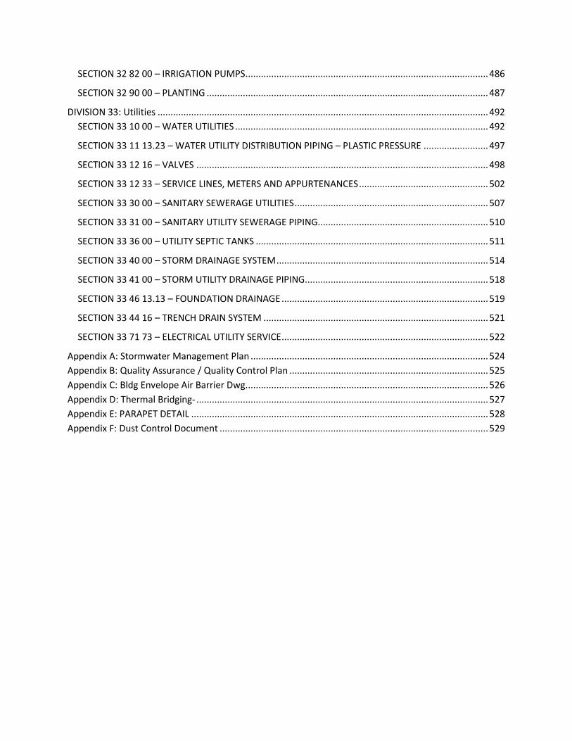
INTRODUCTION ............................................................................................................................................. 1 DIVISION 00: Procurement and Contracting Requirements ....................................................................... 11
SECTION 00 62 00 – CERTIFICATES AND OTHER FORMS......................................................................... 11
SUMMARY OF SOLID WASTE DISPOSAL AND DIVERSION ....................................................................... 12
SECTION 00 72 00 – GENERAL CONDITIONS ........................................................................................... 36
DIVISION 01: General Requirements .......................................................................................................... 37 SECTION 01 11 00 – SUMMARY OF WORK ............................................................................................. 37
SECTION 01 15 00 – UNIVERSAL SPACE STANDARDS.............................................................................. 38
SECTION 01 25 13 – PRODUCT SUBSTITUTION PROCEDURE .................................................................. 40
SECTION 01 26 00 – CONTRACT MODIFICATION PROCEDURES ............................................................. 40
SECTION 01 29 00 – APPLICATION FOR PAYMENT ................................................................................. 40
SECTION 01 29 73 – SCHEDULE OF VALUES ............................................................................................ 40
SECTION 01 32 16 – PROGRESS SCHEDULES AND REPORTS ................................................................... 40
SECTION 01 33 00 – Weather Delays ...................................................................................................... 41
SECTION 01 35 10 – CONSTRUCTION RECYCLING ................................................................................... 42
SECTION 01 35 23 – SAFETY / ENVIRONMENTAL REQUIRMENTS .......................................................... 42
SECTION 01 35 63 – SUSTAINABILITY CERTIFICATION PROJECT REQUIREMENTS .................................. 43
SECTION 01 43 26 – TESTING LABORATORY-AGENCY SERIVCES............................................................. 45
SECTION 01 45 00 – QUALITY CONTROL ................................................................................................. 45
SECTION 01 61 00 – COMMON PRODUCT REQUIREMENTS ................................................................... 45
SECTION 01 66 00 – NON-UTILIZATION OF ASBESTOS MATERIAL .......................................................... 49
SECTION 01 74 00 – CLEANING AND WASTE MANAGMENT .................................................................. 49
SECTION 01 81 13 – SUSTAINABLE DESIGN REQUIREMENTS ................................................................. 52
SECTION 01 81 19 – INDOOR AIR QUALITY REQUIREMENTS .................................................................. 65

SECTION 01 90 00 – LIFE CYCLE COSTING ............................................................................................... 71
SECTION 01 91 00 – COMMISSIONING ................................................................................................... 76
DIVISION 02: Existing Conditions ................................................................................................................ 89 SECTION 02 41 13 – SELECTIVE SITE DEMOLITION ................................................................................. 89
DIVISION 03: Concrete ................................................................................................................................ 90 SECTION 03 00 00 – CONCRETE .............................................................................................................. 90
SECTION 03 05 00 – COMMON WORK RESULTS OF CONCRETE ............................................................. 90
SECTION 03 20 00 – CONCRETE REINFORCING ....................................................................................... 92
SECTION 03 30 00 – CAST-IN-PLACE CONCRETE ..................................................................................... 92
SECTION 03 45 00 – PRECAST ARCHITECTURAL CONCRETE ................................................................... 93
SECTION 03 60 00 – GROUT .................................................................................................................... 94
SECTION 03 90 00 – CONCRETE FINISHING ............................................................................................. 95
DIVISION 04: Masonry ................................................................................................................................ 96 SECTION 04 00 00 – MASONRY ............................................................................................................... 96
SECTION 04 05 13 – MASONRY MORTAR AND GROUT .......................................................................... 97
SECTION 04 20 00 – UNIT MASONRY ...................................................................................................... 99
DIVISION 05: Metals .................................................................................................................................. 107 SECTION 05 00 00 – METALS ................................................................................................................. 107
SECTION 05 12 00 – STRUCTURAL STEEL FRAMING.............................................................................. 108
SECTION 05 21 00 – STEEL JOIST FRAMING .......................................................................................... 111
SECTION 05 31 00 – STEEL DECKING ..................................................................................................... 112
SECTION 05 40 00 – COLD-FORMED METAL FRAMING ........................................................................ 115
SECTION 05 50 00 – METAL FABRICATIONS .......................................................................................... 118
SECTION 05 58 00 – FORMED METAL FABRICATIONS .......................................................................... 123
SECTION 05 60 00 - STEEL STAIRS AND RAILINGS ................................................................................. 125
DIVISION 06: Wood and Plastics ............................................................................................................... 127 SECTION 06 10 00 – ROUGH CARPENTRY ............................................................................................. 127
SECTION 06 20 00 – FINISH CARPENTRY ............................................................................................... 130
SECTION 06 60 00 – PLASTIC FABRICATIONS ........................................................................................ 137
DIVISION 07: Thermal and Moisture Protection ....................................................................................... 139 SECTION 07 05 00 – COMMON WORK RESULTS OF THERMAL AND MOISTURE PROTECTION ............ 139
SECTION 07 10 00 – DAMPPROOFING AND WATERPROOFING ............................................................ 140
SECTION 07 20 00 – THERMAL PROTECTION ........................................................................................ 142

SECTION 07 50 00 – MEMBRANE ROOFING .......................................................................................... 144
SECTION 07 72 33 – ROOF HATCHES .................................................................................................... 146
DIVISION 08: Doors and Windows ............................................................................................................ 146 SECTION 08 00 00 – OPENINGS ............................................................................................................. 146
SECTION 08 05 00 – COMMON WORK RESULTS FOR DOORS AND WINDOWS .................................... 147
SECTION 08 11 00 – METAL DOORS AND FRAMES ............................................................................... 149
SECTION 08 14 00 – WOOD, LAMINATE, AND SPECIALTY DOORS ........................................................ 152
SECTION 08 31 00 – ACCESS DOORS AND PANELS ............................................................................... 154
SECTION 08 33 23 – OVERHEAD COILING DOORS ................................................................................ 154
SECTION 08 41 13 – ALUMINUM-FRAMED ENTRANCES AND STOREFRONTS ...................................... 156
SECTION 08 45 00 – TRANSLUCENT WALL AND ROOF ASSEMBLIES ..................................................... 159
SECTION 08 50 00 – WINDOWS ............................................................................................................ 160
Glass and Glazing for Aluminum Clad Wood Windows. ........................................................................... 160 SECTION 08 62 00 – UNIT SKYLIGHTS ................................................................................................... 164
SECTION 08 70 00 - HARDWARE ........................................................................................................... 165
SECTION 08 80 00 – GLAZING ............................................................................................................... 175
DIVISION 09 Finishes ................................................................................................................................. 178 SECTION 09 05 00 – COMMON WORK RESULTS FOR FINISHES ............................................................ 178
SECTION 09 29 00 - GYPSUM BOARD .................................................................................................... 178
SECTION 09 51 00 – ACOUSTICAL CEILINGS .......................................................................................... 182
SECTION 09 60 00 – FLOORING ............................................................................................................. 184
SECTION 09 98 60 – FIBER REINFORCED PANELS .................................................................................. 196
SECTION 09 95 00 – WALL COVERING .................................................................................................. 196
SECTION 09 90 00 – PAINTS AND COATINGS ........................................................................................ 198
DIVISION 10: Specialties ............................................................................................................................ 206 SECTION 10 05 00 – COMMON WORK RESULTS OF SPECIALTIES ......................................................... 206
SECTION 10 14 00 - SIGNAGE ................................................................................................................ 206
SECTION 10 21 00 – COMPARTMENTS AND CUBICLES ......................................................................... 208
SECTION 10 22 00 – PARTITIONS .......................................................................................................... 211
SECTION 10 28 00 – TOILET, BATH, AND LAUNDRY ACCESSORIES ....................................................... 214
SECTION 10 44 00 – FIRE EXTINGUISHERS, CABINETS, AND ACCESSORIES .......................................... 216
SECTION 10 51 13 – LOCKERS AND LOCKER ROOM BENCHES .............................................................. 217
SECTION 10 56 00 - STORAGE ASSEMBLIES .......................................................................................... 219

SECTION 10 57 00 – WARDROBE AND CLOSET SPECIALTIES................................................................. 220
SECTION 10 75 00 – ALUMINUM FLAGPOLES ....................................................................................... 221
DIVISION 11: Equipment ........................................................................................................................... 224 SECTION 11 13 00 – LOADING DOCK EQUIPMENT ............................................................................... 224
SECTION 11 31 00 – RESIDENTIAL APPLIANCES .................................................................................... 224
SECTION 11 40 00 – KITCHEN EQUIPMENT ........................................................................................... 225
DIVISION 12: Furnishings .......................................................................................................................... 233 SECTION 12 05 00 – COMMON WORK RESULTS OF FURNISHINGS ...................................................... 233
SECTION 12 20 00 – WINDOW TREATMENTS ....................................................................................... 233
SECTION 12 30 00 – CASEWORK ........................................................................................................... 239
SECTION 12 50 00 – FURNITURE ........................................................................................................... 240
DIVISION 13: Special Construction ............................................................................................................ 240 SECTION 13 27 00 – VAULTS ................................................................................................................. 240
DIVISION 14: Conveying Equipment ......................................................................................................... 243 SECTION 14 20 00 – ELEVATORS ........................................................................................................... 243
DIVISION 21: Fire Suppression .................................................................................................................. 248 SECTION 21 05 00 – COMMON WORK RESULTS OF FIRE PROTECTION ................................................ 248
SECTION 21 11 00 – FACILITY FIRE-SUPPRESSION WATER-SERVICE PIPING ......................................... 248
DIVISION 22: Plumbing.............................................................................................................................. 251 SECTION 22 05 00 – COMMON WORK RESULTS FOR PLUMBING ........................................................ 251
SECTION 22 05 19 – METERS AND GAUGES FOR PLUMBING PIPING ................................................... 253
SECTION 22 05 23 – GENERAL-DUTY VALVES AND UNIONS FOR PLUMBING ....................................... 259
SECTION 22 05 29 – HANGERS AND SUPPORTS FOR PLUMBING PIPING AND EQUIPMENT ................ 262
SECTION 22 05 48 – VIBRATION AND SEISMIC CONTROL FOR PLUMBING PIPING AND EQUIPMENT . 272
SECTION 22 05 53 – IDENTIFICATION FOR PLUMBING PIPING AND EQUIPMENT ................................ 275
SECTION 22 07 16 – PLUMBING EQUIPMENT INSULATION .................................................................. 279
SECTION 22 07 19 – PLUMBING PIPING INSULATION ........................................................................... 281
SECTION 22 11 13 – FACILITY WATER DISTRIBUTION PIPING ............................................................... 284
SECTION 22 11 23 – FACILITY NATURAL GAS PIPING ............................................................................ 292
SECTION 22 13 16 – SANITARY WASTE AND VENT PIPING ................................................................... 296
SECTION 22 13 23 – SANITARY WASTE INTERCEPTORS ........................................................................ 300
SECTION 22 14 13 – FACILITY STORM DRAINAGE PIPING ..................................................................... 301
SECTION 22 16 00 – KITCHEN PIPING ................................................................................................... 303

SECTION 22 30 00 – PLUMBING EQUIPMENT ....................................................................................... 304
SECTION 22 31 00 – WATER TREATMENT ............................................................................................. 307
SECTION 22 33 00 – DOMESTIC WATER HEATERS ................................................................................ 310
SECTION 22 40 00 – PLUMBING FIXTURES............................................................................................ 312
SECTION 22 70 00 – PUMPS .................................................................................................................. 315
SECTION 22 80 00 IRRIGATION INSTALLATION ..................................................................................... 318
DIVISION 23: Heating, Ventilation, and Air Conditioning ......................................................................... 328 SECTION 23 05 00 – COMMON WORK RESULTS FOR HVAC ................................................................. 328
SECTION 23 05 29 – HANGERS AND SUPPORTS HVAC .......................................................................... 332
SECTION 23 05 53 – IDENTIFICATION FOR HVAC EQUIPMENT ............................................................. 334
SECTION 23 05 93 – TESTING, ADJUSTING, AND BALANCING FOR HVAC ............................................. 335
SECTION 23 07 00 – HVAC INSULATION .................................................................................................... 337 SECTION 23 30 00 – HVAC AIR DISTRIBUTION ...................................................................................... 338
SECTION 23 31 13 – DUCTWORK .......................................................................................................... 341
SECTION 23 33 00 – AIR DUCT ACCESSORIES ........................................................................................ 344
SECTION 23 34 00 – HVAC FANS ........................................................................................................... 347
SECTION 23 35 13 – DUST COLLECTION SYSTEMS ................................................................................ 348
SECTION 23 36 00 – AIR TERMINAL UNITS............................................................................................ 350
SECTION 23 37 00 – AIR OUTLETS AND INLETS ..................................................................................... 350
SECTION 23 50 00 – CENTRAL HEATING EQUIPMENT .......................................................................... 351
SECTION 23 51 00 – BREECHINGS, CHIMNEYS, AND STACKS................................................................ 354
SECTION 23 52 00 – HEATING BOILERS ................................................................................................. 355
SECTION 23 55 00 – FUEL-FIRED HEATERS ............................................................................................ 357
SECTION 23 57 00 – HEAT EXCHANGERS FOR HVAC ............................................................................. 358
SECTION 23 60 00 – CENTRAL COOLING EQUIPMENT .......................................................................... 358
SECTION 23 65 13 – FORCED-DRAFT COOLING TOWERS ...................................................................... 363
SECTION 23 71 20 – GLYCOL SYSTEMS .................................................................................................. 364
SECTION 23 72 00 – OUTDOOR AIR VENTILATION (AIR TO AIR SYSTEMS) ........................................... 365
SECTION 23 74 00 – PACKAGED OUTDOOR HVAC EQUIPMENT ........................................................... 366
SECTION 23 81 43 – HEAT PUMPS ........................................................................................................ 367
DIVISION 25: Integrated Automation ....................................................................................................... 368 SECTION 25 00 00 – INTEGRATED AUTOMATION ................................................................................. 368

SECTION 25 09 23 – DIRECT-DIGITAL CONTROL SYSTEM FOR HVAC .................................................... 371
SECTION 25 09 33 – ELECTRIC AND ELECTRONIC CONTROL SYSTEM FOR HVAC ................................. 372
SECTION 25 13 00 – INTEGRATED AUTOMATION CONTROL AND MONITORING NETWORK (DASHBOARDS) ..................................................................................................................................... 376
DIVISION 26: Electrical .............................................................................................................................. 380 SECTION 26 01 00 – GENERAL REQUIREMENTS .................................................................................... 380
SECTION 26 01 00 – ARC FLASH HAZARD STUDY ................................................................................. 382
SECTION 26 01 26 – MAINTENANCE TESTING OF ELECTRICAL SYSTEMS .............................................. 387
SECTION 26 05 00 – COMMON WORK RESULTS OF ELECTRICAL .......................................................... 387
SECTION 26 05 26 – GROUNDING AND BONDING FOR ELECTRICAL SYSTEMS ..................................... 390
SECTION 26 12 00 – MEDIUM VOLTAGE TRANSFORMERS ................................................................... 390
SECTION 26 24 00 – PANELBOARDS ...................................................................................................... 391
SECTION 26 32 00 – PACKAGED GENERATOR ASSEMBLIES .................................................................. 392
SECTION 26 50 00 – LIGHTING .............................................................................................................. 392
SECTION 26 56 29 – SITE LIGHTING ...................................................................................................... 393
SECTION 26 57 00 – PROGRAMMABLE LIGHTING CONTROL SYSTEM .................................................. 394
DIVISION 27: Communications & Technology .......................................................................................... 395 SECTION 27 20 00 – DATA COMMUNICATIONS / SECTION 27 30 00 – VOICE COMMUNICATIONS ..... 406
SECTION 27 40 00 – AUDIOVISUAL SYSTEMS........................................................................................ 425
SECTION 27 50 00 – PROGRAMMABLE COMMUNICATIONS SYSTEMS ................................................ 426
DIVISION 28: Electronic Safety and Security ............................................................................................. 426 SECTION 28 05 00 – COMMON WORK RESULTS FOR ELECTRONIC SAFETY AND SECURITY ................. 426
SECTION 28 13 53 – ACCESS SYSTEM .................................................................................................... 428
SECTION 28 23 00 – VIDEO SURVEILLANCE .......................................................................................... 429
SECTION 28 31 00 – FIRE DETECTION AND ALARM .............................................................................. 430
DIVISION 31: Earthwork ............................................................................................................................ 457 SECTION 31 00 00 – EARTHWORK ........................................................................................................ 457
SECTION 31 10 00 – SITE CLEARING ...................................................................................................... 467
SECTION 31 23 00 – EXCAVATION AND FILL ......................................................................................... 468
DIVISION 32: Exterior Improvements ....................................................................................................... 474 SECTION 32 05 00 – COMMON WORK RESULTS OF EXTERIOR IMPROVEMENTS ................................. 474
SECTION 32 10 00 – PAVING, SIDEWALKS, AND CURBING ................................................................... 474
SECTION 32 80 00 – IRRIGATION .......................................................................................................... 478
SECTION 32 82 00 – IRRIGATION PUMPS .............................................................................................. 486
SECTION 32 90 00 – PLANTING ............................................................................................................. 487
DIVISION 33: Utilities ................................................................................................................................ 492 SECTION 33 10 00 – WATER UTILITIES .................................................................................................. 492
SECTION 33 11 13.23 – WATER UTILITY DISTRIBUTION PIPING – PLASTIC PRESSURE ......................... 497
SECTION 33 12 16 – VALVES ................................................................................................................. 498
SECTION 33 12 33 – SERVICE LINES, METERS AND APPURTENANCES .................................................. 502
SECTION 33 30 00 – SANITARY SEWERAGE UTILITIES ........................................................................... 507
SECTION 33 31 00 – SANITARY UTILITY SEWERAGE PIPING.................................................................. 510
SECTION 33 36 00 – UTILITY SEPTIC TANKS .......................................................................................... 511
SECTION 33 40 00 – STORM DRAINAGE SYSTEM .................................................................................. 514
SECTION 33 41 00 – STORM UTILITY DRAINAGE PIPING....................................................................... 518
SECTION 33 46 13.13 – FOUNDATION DRAINAGE ................................................................................ 519
SECTION 33 44 16 – TRENCH DRAIN SYSTEM ....................................................................................... 521
SECTION 33 71 73 – ELECTRICAL UTILITY SERVICE ................................................................................ 522
Appendix A: Stormwater Management Plan ............................................................................................ 524 Appendix B: Quality Assurance / Quality Control Plan ............................................................................. 525 Appendix C: Bldg Envelope Air Barrier Dwg. ............................................................................................. 526 Appendix D: Thermal Bridging- ................................................................................................................. 527 Appendix E: PARAPET DETAIL ................................................................................................................... 528 Appendix F: Dust Control Document ........................................................................................................ 529

February 2016 Division 00: Procurement and Contracting 11
DIVISION 00: Procurement and Contracting Requirements
SECTION 00 62 00 – CERTIFICATES AND OTHER FORMS Part 1: General 1.01 Summary
A. Construction Waste Diversion Form B. Recycled Content of Materials Form C. Minimum Sustainability Reporting Requirements D. Building Asbestos Free Certification Form
February 2016 Division 00: Procurement and Contracting 12
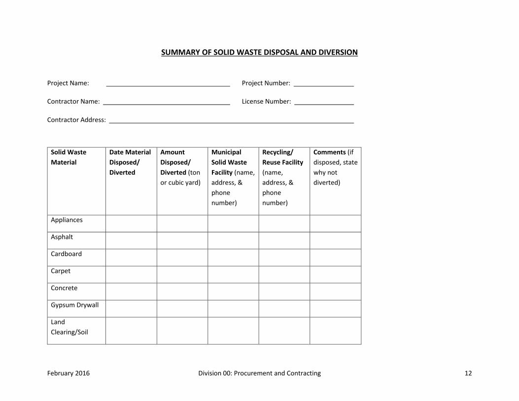
SUMMARY OF SOLID WASTE DISPOSAL AND DIVERSION
Project Name: Project Number:
Contractor Name: License Number:
Contractor Address:
Solid Waste Material
Date Material Disposed/ Diverted
Amount Disposed/ Diverted (ton or cubic yard)
Municipal Solid Waste Facility (name, address, & phone number)
Recycling/ Reuse Facility (name, address, & phone number)
Comments (if disposed, state why not diverted)
Appliances
Asphalt
Cardboard
Carpet
Concrete
Gypsum Drywall
Land Clearing/Soil

February 2016 Division 00: Procurement and Contracting 13
Masonry
Metals: Ferrous
Metals: Non-ferrous
Mixed/Co-mingled Waste
Plastic
Roofing: Asphalt-based
Roofing: EPDM
Salvaged/Surplus Materials for Reuse
Wood: Land clearing Debris
Wood: Scrap Lumber
Ceiling Tiles
Other:
February 2016 Division 00: Procurement and Contracting 14
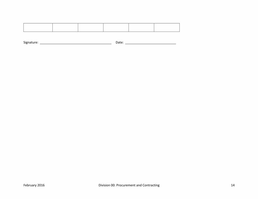
Signature: Date:

February 2016 Division 00: Procurement and Contracting 15
AFFIRMATIVE PROCUREMENT REPORTING FORM Recycled Content Materials & Biobased Content Materials
Project Name: Project Number:
Contractor Name: License Number:
Contractor Address:
Product Total $ value
provided
Total $ value w/ recycled content
Pre-consume
r
Total $ value w/ recycled content
Post-consume
r
Total $ value w/ bio based content
Exempted indicate 1,2,3,4
Comments
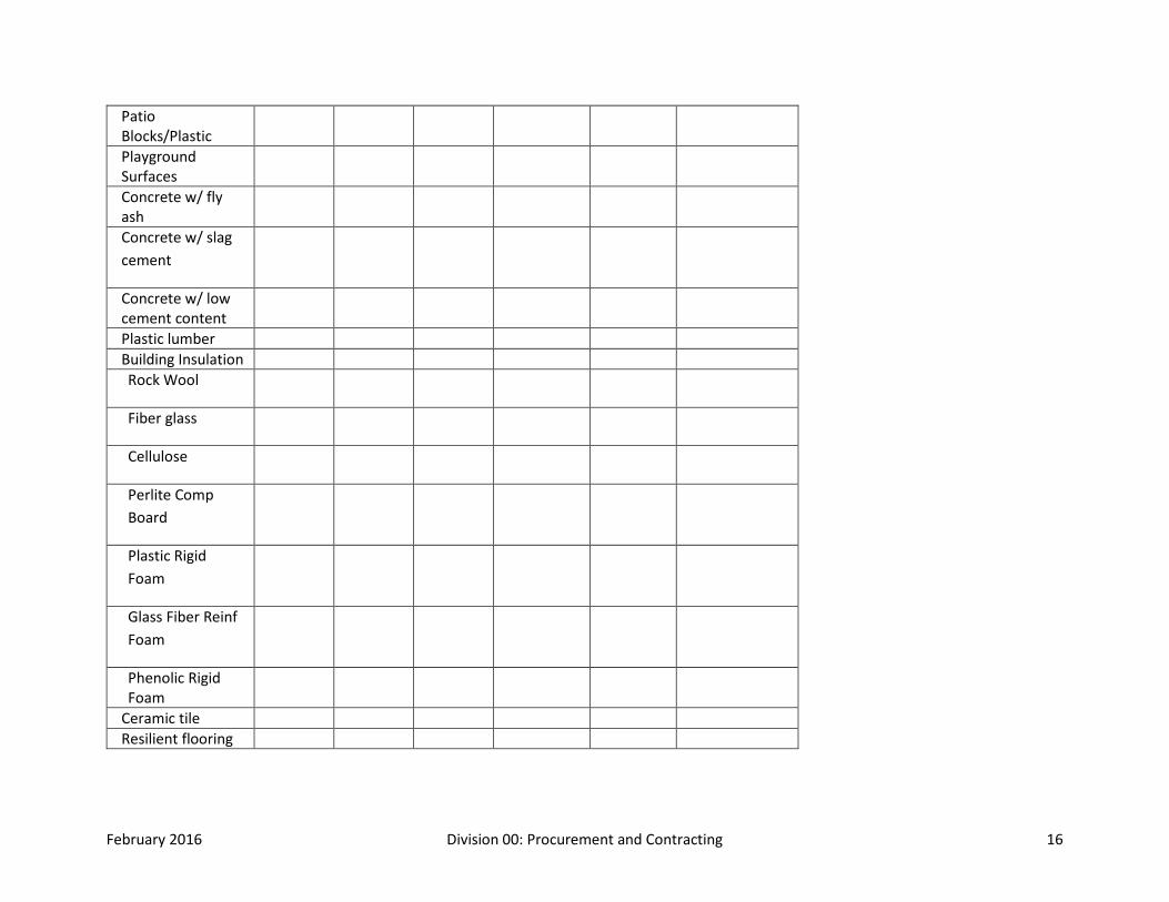
Hydraulic Mulch (paper based)
Hydraulic Mulch (wood based)
Compost Parking Stops (Concrete w/ fly ash, slag cement or low cement content)
Parking Stops (Plastic/Rubber)
Patio Blocks/Rubber
February 2016 Division 00: Procurement and Contracting 16
Patio Blocks/Plastic
Playground Surfaces
Concrete w/ fly ash
Concrete w/ slag cement
Concrete w/ low cement content
Plastic lumber Building Insulation Rock Wool
Fiber glass
Cellulose
Perlite Comp Board
Plastic Rigid Foam
Glass Fiber Reinf Foam
Phenolic Rigid Foam
Ceramic tile Resilient flooring

February 2016 Division 00: Procurement and Contracting 17
Floor Tiles/Rubber
Floor Tiles/Plastic Running Tracks
Carpet (PET) Paint Reprocessed Latex Paint White & Light Colors
Reprocessed Latex Dark Colors
Consolidated Latex Paint
toilet/shower partitions (plastic or steel)
Other
CERTIFICATION
I hereby certify the information provided herein is accurate and that the requisition/procurement of all materials listed on this form comply with current EPA standards for recycled/recovered materials content.
The following exemptions may apply to the non-procurement of recycled/recovered content materials:
February 2016 Division 00: Procurement and Contracting 18
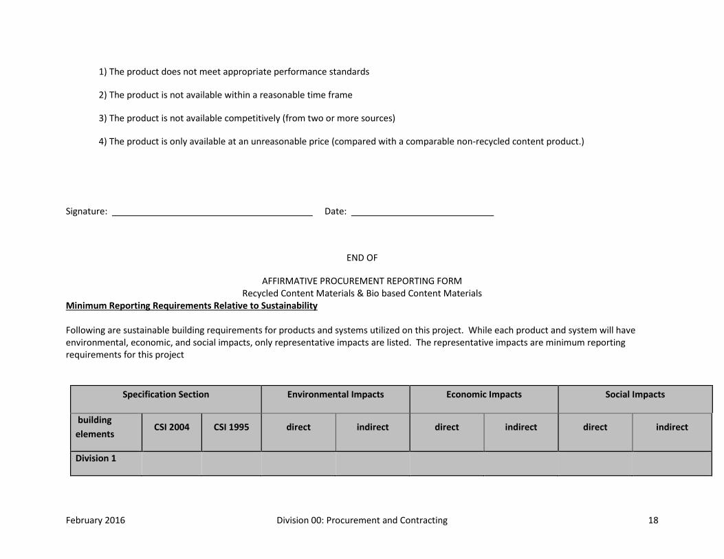
1) The product does not meet appropriate performance standards
2) The product is not available within a reasonable time frame
3) The product is not available competitively (from two or more sources)
4) The product is only available at an unreasonable price (compared with a comparable non-recycled content product.)
Signature: Date:
END OF
AFFIRMATIVE PROCUREMENT REPORTING FORM Recycled Content Materials & Bio based Content Materials
Minimum Reporting Requirements Relative to Sustainability Following are sustainable building requirements for products and systems utilized on this project. While each product and system will have environmental, economic, and social impacts, only representative impacts are listed. The representative impacts are minimum reporting requirements for this project
Specification Section Environmental Impacts Economic Impacts Social Impacts
building elements
CSI 2004 CSI 1995 direct indirect direct indirect direct indirect
Division 1

February 2016 Division 00: Procurement and Contracting 19
summary 01 10 00 01100 green building rating
certification
total cost for green features and consulting
services
EPA National Performance
Track
continual improvement of environmental quality
01 43 50 01435 environmental performance summary per
building rating program &
consistent with Agency EMS
documentation of contractor’s Environmental Management System (EMS)
Energy Star performance
rating
IAQ management
01 57 19.11 01352 total cost estimated $ value of worker
productivity based on IAQ impact of 3%
noise management
01 57 19.12 01353 total cost dB maximum level and duration
environmental management
01 57 19.13 01354 compliance with NPDES
relationship to adjacent & connected:
wildlife corridors,
natural
total cost coordination with Agency
EMS protocols
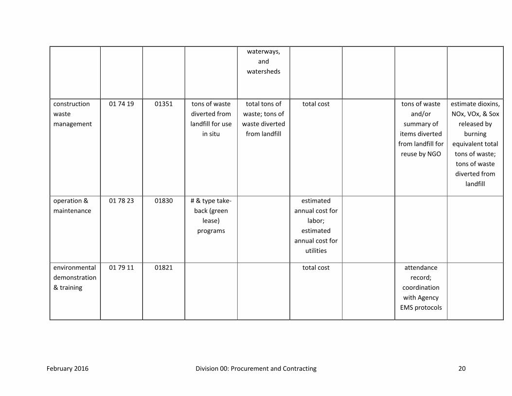
February 2016 Division 00: Procurement and Contracting 20
waterways, and
watersheds
construction waste management
01 74 19 01351 tons of waste diverted from landfill for use
in situ
total tons of waste; tons of waste diverted
from landfill
total cost tons of waste and/or
summary of items diverted
from landfill for reuse by NGO
estimate dioxins, NOx, VOx, & Sox
released by burning
equivalent total tons of waste; tons of waste diverted from
landfill
operation & maintenance
01 78 23 01830 # & type take-back (green
lease) programs
estimated annual cost for
labor; estimated
annual cost for utilities
environmental demonstration & training
01 79 11 01821 total cost attendance record;
coordination with Agency
EMS protocols
February 2016 Division 00: Procurement and Contracting 21
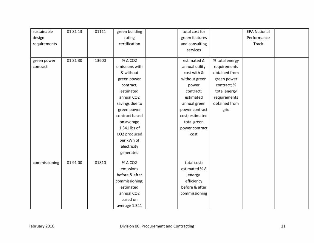
sustainable design requirements
01 81 13 01111 green building rating
certification
total cost for green features and consulting
services
EPA National Performance
Track
green power contract
01 81 30 13600 % Δ CO2 emissions with
& without green power
contract; estimated
annual CO2 savings due to green power
contract based on average 1.341 lbs of
CO2 produced per kWh of electricity generated
estimated Δ annual utility cost with &
without green power
contract; estimated
annual green power contract cost; estimated
total green power contract
cost
% total energy requirements obtained from green power contract; % total energy
requirements obtained from
grid
commissioning 01 91 00 01810 % Δ CO2 emissions
before & after commissioning;
estimated annual CO2
based on average 1.341
total cost; estimated % Δ
energy efficiency
before & after commissioning
February 2016 Division 00: Procurement and Contracting 22
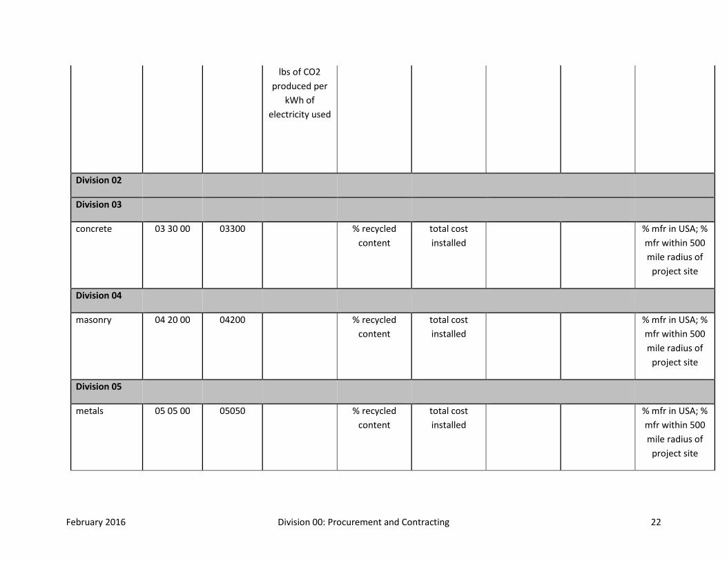
lbs of CO2 produced per
kWh of electricity used
Division 02
Division 03
concrete 03 30 00 03300 % recycled content
total cost installed
% mfr in USA; % mfr within 500 mile radius of
project site
Division 04
masonry 04 20 00 04200 % recycled content
total cost installed
% mfr in USA; % mfr within 500 mile radius of
project site
Division 05
metals 05 05 00 05050 % recycled content
total cost installed
% mfr in USA; % mfr within 500 mile radius of
project site

February 2016 Division 00: Procurement and Contracting 23
structural metal framing
05 10 00 05100 % recycled content
total cost installed
% mfr in USA; % mfr within 500 mile radius of
project site
Division 06
rough carpentry
06 10 00 06100 % non-CCA treated wood
% wood from certified
sustainably managed forests; % alternative
species
total cost installed
% non-urea formaldehyde treated wood
% wood from USA forests
finish carpentry
06 20 00 06200 % wood from certified
sustainably managed forests; % alternative
species
total cost installed
% non-urea formaldehyde treated wood
% wood from USA forests
plastic fabrications
06 60 00 06600 % recycled content
total cost installed
% mfr in USA; % mfr within 500 mile radius of
project site
alternative agricultural products
06 90 00 06700 % biobased content
total cost installed
% bio based from USA
agriculture
February 2016 Division 00: Procurement and Contracting 24
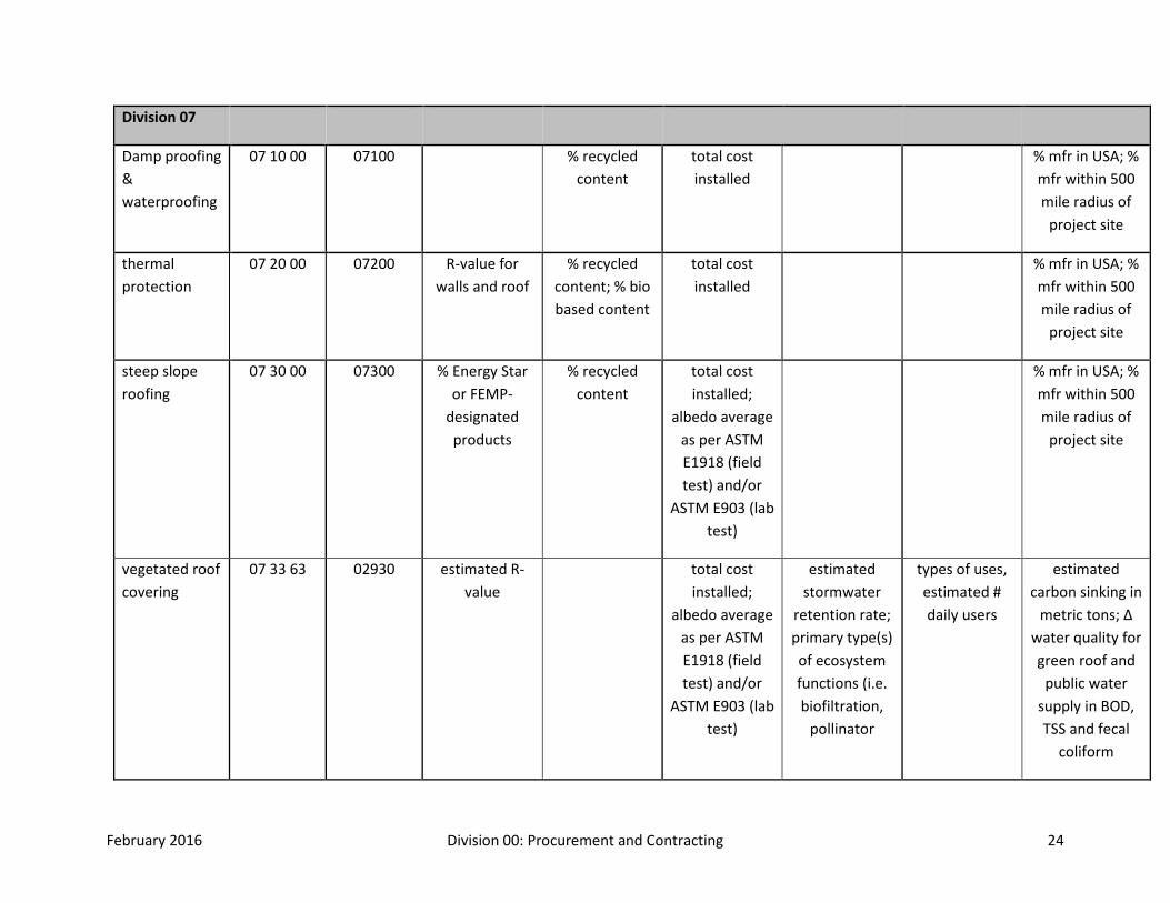
Division 07
Damp proofing & waterproofing
07 10 00 07100 % recycled content
total cost installed
% mfr in USA; % mfr within 500 mile radius of
project site
thermal protection
07 20 00 07200 R-value for walls and roof
% recycled content; % bio based content
total cost installed
% mfr in USA; % mfr within 500 mile radius of
project site
steep slope roofing
07 30 00 07300 % Energy Star or FEMP-
designated products
% recycled content
total cost installed;
albedo average as per ASTM E1918 (field test) and/or
ASTM E903 (lab test)
% mfr in USA; % mfr within 500 mile radius of
project site
vegetated roof covering
07 33 63 02930 estimated R-value
total cost installed;
albedo average as per ASTM E1918 (field test) and/or
ASTM E903 (lab test)
estimated stormwater
retention rate; primary type(s) of ecosystem functions (i.e. biofiltration,
pollinator
types of uses, estimated # daily users
estimated carbon sinking in
metric tons; Δ water quality for green roof and
public water supply in BOD, TSS and fecal
coliform
February 2016 Division 00: Procurement and Contracting 25
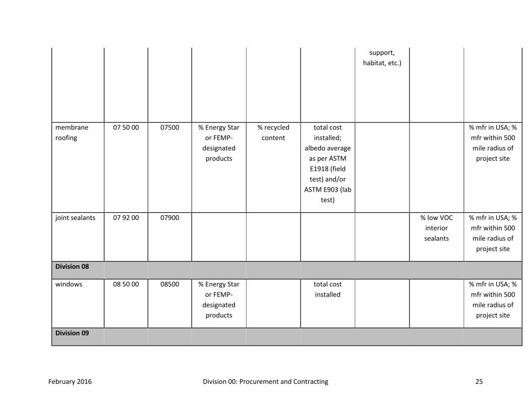
support, habitat, etc.)
membrane roofing
07 50 00 07500 % Energy Star or FEMP-
designated products
% recycled content
total cost installed;
albedo average as per ASTM E1918 (field test) and/or
ASTM E903 (lab test)
% mfr in USA; % mfr within 500 mile radius of
project site
joint sealants 07 92 00 07900 % low VOC interior sealants
% mfr in USA; % mfr within 500 mile radius of
project site
Division 08
windows 08 50 00 08500 % Energy Star or FEMP-
designated products
total cost installed
% mfr in USA; % mfr within 500 mile radius of
project site
Division 09
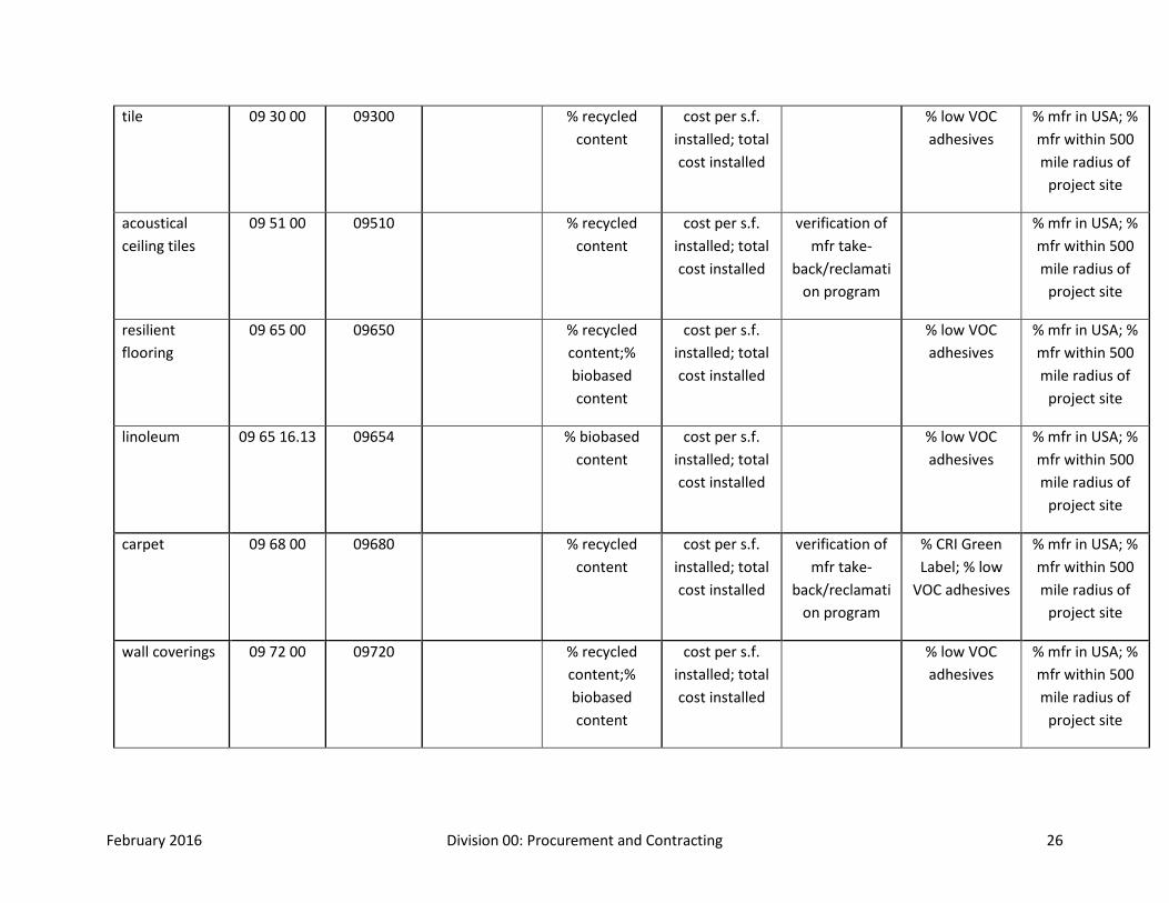
February 2016 Division 00: Procurement and Contracting 26
tile 09 30 00 09300 % recycled content
cost per s.f. installed; total cost installed
% low VOC adhesives
% mfr in USA; % mfr within 500 mile radius of
project site
acoustical ceiling tiles
09 51 00 09510 % recycled content
cost per s.f. installed; total cost installed
verification of mfr take-
back/reclamation program
% mfr in USA; % mfr within 500 mile radius of
project site
resilient flooring
09 65 00 09650 % recycled content;% biobased content
cost per s.f. installed; total cost installed
% low VOC adhesives
% mfr in USA; % mfr within 500 mile radius of
project site
linoleum 09 65 16.13 09654 % biobased content
cost per s.f. installed; total cost installed
% low VOC adhesives
% mfr in USA; % mfr within 500 mile radius of
project site
carpet 09 68 00 09680 % recycled content
cost per s.f. installed; total cost installed
verification of mfr take-
back/reclamation program
% CRI Green Label; % low
VOC adhesives
% mfr in USA; % mfr within 500 mile radius of
project site
wall coverings 09 72 00 09720 % recycled content;% biobased content
cost per s.f. installed; total cost installed
% low VOC adhesives
% mfr in USA; % mfr within 500 mile radius of
project site

February 2016 Division 00: Procurement and Contracting 27
paint 09 90 00 09900 % recycled content
cost per s.f. installed; total cost installed
% low VOC; % Green Seal
labeled
% mfr in USA; % mfr within 500 mile radius of
project site
Division 10
plastic toilet compartments
10 21 13.19 10170 % recycled content
total cost installed
% mfr in USA; % mfr within 500 mile radius of
project site
bat houses 10 81 16.13 02872 # houses; estimated #
bats accommodated
relationship to adjacent & connected:
wildlife corridors,
natural waterways,
and watersheds
total cost installed
% mfr in USA; % mfr within 500 mile radius of
project site
integrated pest management (IPM)
10 81 50 10295 total cost estimated $ value of worker
productivity based on IAQ impact of 3%
estimated grams or liters (solid or
liquid) of conventional
pesticides avoided annually
Division 11

February 2016 Division 00: Procurement and Contracting 28
loading dock equipment
11 13 00 11160 % recycled content
total cost installed
% mfr in USA; % mfr within 500 mile radius of
project site
office equipment
11 28 00 11680 % Energy Star or FEMP-
designated products
total cost installed
% mfr in USA; % mfr within 500 mile radius of
project site
residential equipment
11 30 00 11450 % Energy Star or FEMP-
designated products
total cost installed
% mfr in USA; % mfr within 500 mile radius of
project site
Division 12
artwork 12 10 00 12100 % recycled content
total cost installed
% mfr in USA; % mfr within 500 mile radius of
project site
floor mats 12 48 13 12482 % recycled content
total cost installed
% mfr in USA; % mfr within 500 mile radius of
project site

February 2016 Division 00: Procurement and Contracting 29
systems furniture
12 59 00 12700 % recycled content;
%biobased content; % wood from
certified sustainably managed forests; % alternative
species
total cost installed
verification of mfr take-
back/reclamation program
% low VOC adhesives
% mfr in USA; % mfr within 500 mile radius of
project site
Division 13
Division 14
elevators 14 20 00 14200 Motor Master assessment
% biobased hydraulic fluids
total cost installed
% mfr in USA; % mfr within 500 mile radius of
project site
Division 15-30
plumbing fixtures & equipment
22 40 00 15400 % reduction in water use from
baseline (Energy Policy Act 1992); %
FEMP-
total cost installed
% mfr in USA; % mfr within 500 mile radius of
project site
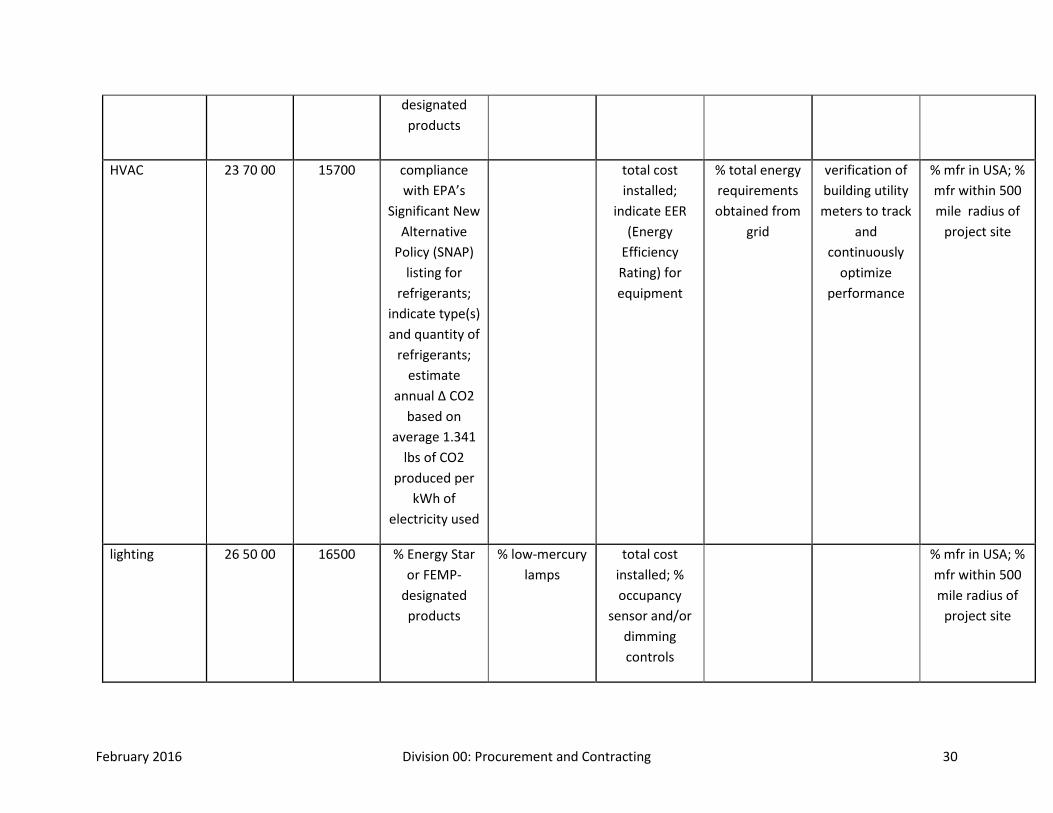
February 2016 Division 00: Procurement and Contracting 30
designated products
HVAC 23 70 00 15700 compliance with EPA’s
Significant New Alternative
Policy (SNAP) listing for
refrigerants; indicate type(s) and quantity of
refrigerants; estimate
annual Δ CO2 based on
average 1.341 lbs of CO2
produced per kWh of
electricity used
total cost installed;
indicate EER (Energy
Efficiency Rating) for equipment
% total energy requirements obtained from
grid
verification of building utility meters to track
and continuously
optimize performance
% mfr in USA; % mfr within 500 mile radius of
project site
lighting 26 50 00 16500 % Energy Star or FEMP-
designated products
% low-mercury lamps
total cost installed; % occupancy
sensor and/or dimming controls
% mfr in USA; % mfr within 500 mile radius of
project site
February 2016 Division 00: Procurement and Contracting 31
Division 31-40
stormwater management by compost
31 25 73 02635 % Δ estimated soil
productivity before & after
compost (assume 12
month application)
% biobased content
total cost installed
estimated stormwater
retention rate
% mfr in USA; % mfr within 500 mile radius of
project site
soil treatment 31 31 00 02360 gallons termiticide
avoided
relationship to adjacent & connected: water table,
natural waterways and
watersheds
total cost installed
bases, ballasts & pavement
32 10 00 02700 % recycled content
total cost installed;
albedo average as per ASTM E1918 (field test) and/or
ASTM E903 (lab test)
% mfr in USA; % mfr within 500 mile radius of
project site
February 2016 Division 00: Procurement and Contracting 32
porous paving 32 12 43 02795 minimum permeability
rate
% recycled content
total cost installed;
albedo average as per ASTM E1918 (field test) and/or
ASTM E903 (lab test)
estimated stormwater
retention rate
% mfr in USA; % mfr within 500 mile radius of
project site
constructed wetlands
32 71 00 02670 estimated gallons water diverted from
public treatment
system annually
total cost installed
estimated carbon sinking in
metric tons; Δ water quality for
wetlands and public water
supply in BOD, TSS and fecal
coliform
planting irrigation
32 84 00 02810 % reduction in water use from
baseline (Energy Policy
Act 1992)
total cost installed
% mfr in USA; % mfr within 500 mile radius of
project site

February 2016 Division 00: Procurement and Contracting 33
planting 32 90 00 02900 % reduction in water use from
baseline (Energy Policy
Act 1992)
s.f. native landscaping;
primary type(s) of ecosystems
on site; primary type(s) of connection
to wildlife corridors
total cost installed;
albedo average as per ASTM E1918 (field test) and/or
ASTM E903 (lab test)
estimated stormwater
retention rate; primary type(s) of ecosystem functions (i.e. biofiltration,
pollinator support,
habitat, etc.)
types of uses, estimated # daily users
estimated carbon sinking in
metric tons
rainwater harvesting
33 16 20 11201 % reduction in water use from
baseline (Energy Policy
Act 1992)
estimated annual rain
water collection in gallons; %
estimate rain water used in lieu of public
supply
estimated stormwater
retention rate
% mfr in USA; % mfr within 500 mile radius of project site; Δ
water quality for rain water
harvested and public water
supply in BOD, TSS and fecal
coliform
Division 41-49
water reuse 44 40 10 11202 % reduction in water use from
baseline (Energy Policy
Act 1992
estimated gallons water diverted from
public treatment
total cost installed
Δ water quality for reclaimed
water and potable water supply in BOD,

February 2016 Division 00: Procurement and Contracting 34
system annually
TSS and fecal coliform
renewable energy systems
48 14 00;
48 15 00
13600 % Δ CO2 emissions with
& without renewable
energy systems;
estimated annual CO2
savings due to renewable
energy systems based on
average 1.341 lbs of CO2
produced per kWh of
electricity generated
total cost installed; estimated
annual energy generation in
BtUs; % estimate
renewable energy used in lieu of public
supply
% total energy requirements obtained from
renewable energy
systems; % total energy
requirements obtained from
grid
% mfr in USA; % mfr within 500 mile radius of
project site
END OF SECTION 00 62 00
SECTION 00 70 00 – CONDITIONS OF CONTRACT
February 2016 Division 00: Procurement and Contracting 35
Part 1: General 1.01 Summary
A. Preference will be given to contractors who demonstrate sustainability in their own operations and incorporate the highest level of sustainable practices feasible
B. Performance Contract C. Integrated Project Delivery
ASBESTOS FREE CERTIFICATION FORM Date: City of Fort Collins Project Manager City of Fort Collins Operation Services P.O. Box 580 Fort Collins, CO. 80528 Project Title - Asbestos Free Certification Letter Project Manager This letter is to certify there were no asbestos materials either specified to be used in the construction documents or any asbestos material brought on site or incorporated in to the building construction at the following address. Project Address: _________________________________________________________. ARCHITECT OF RECORD: CONTRACTOR:
February 2016 Division 00: Procurement and Contracting 36
Name of Firm Name of Firm Printed Name Printed Name Signature Signature Date Date
END OF SECTION 00 70 00
SECTION 00 72 00 – GENERAL CONDITIONS Part 1: General 1.01 Summary The “General Conditions of the Contract for Construction” AIA Document A201, 2007 Edition, as issued by The American Institute of Architects and amended by City of Fort Collins shall be used on this Project.
END OF SECTION 00 72 00

February 2016 01: General Requirements 37
DIVISION 01: General Requirements
SECTION 01 11 00 – SUMMARY OF WORK Refer to RFP or Bid documents for scope of work in relation to a specific project.
1. Design and construction shall conform to or exceed the minimum applicable standards of the City of Fort Collins Zoning and Building Codes, City of Fort Collins Green Building Code, the Fort Collins’ Energy Code for commercial, industrial and high-rise residential buildings, Fort Collins’ City Plan, LEED Gold rating, Larimer County Health Department (Typically applicable to commercial kitchens), and the ADA.
2. With respect to additional governing jurisdictional authorities, they shall be referred to as supportive and/or in addition to the City Building Code requirements when applicable. The following authorities shall be considered in any given project design: • Poudre Fire Authority • Larimer County Health Department • City of Fort Collins Community Planning • City of Fort Collins Utility Services • City of Fort Collins Cultural Library and Recreation Services • City of Fort Collins Transportation Services
3. Specific Code requirements are to be adhered to when referring to kitchen facilities, restroom facilities, firefighting access and fire exiting/life safety aspects, swimming/wading pools and HVAC systems.
4. All new projects to be reviewed by a third party for ADA compliance in the design development phase.
5. Security drawings to be reviewed by Risk Management at schematic design development stage. 6. All project participants will furnish owner with a complete construction set and as-builts of project
drawings and materials including electronic drawings. Electronic files will be available to the owner at any time during the project. Format shall be AutoCAD, Revit, or Sketchup for electronic files. Files are required from any discipline that worked on the project; including but not limited to: architect; civil, structural, mechanical, plumbing, or electrical engineer; interior designer; landscape architect; energy modeler; sustainability consultant; or commissioning agent.
o Files are required at the time of 100% CD and any addendums that are issued. o Upon completion of the project, each discipline including but not limited to Architect,
Engineers, consultants, commissioning agents, etc. shall submit a complete and up to date set of record drawings, both in electronic and paper versions. These record drawings shall be submitted to the P.M. no later than 30 days after completion of the project.
o Note that all final material selections and correct keys must be included as a part of the record drawings
7. All Operation and Maintenance Manuals and a Materials Chart listing each material and product used in the new building shall be submitted electronically to the project manager or facility designer at the completion of the project.

February 2016 01: General Requirements 38
SECTION 01 15 00 – UNIVERSAL SPACE STANDARDS Employee spaces to be in compliance with the square footage below for all new construction and any renovation where furniture is replaced. Square footage allowances are based on primarily on employee location on City organizational chart. Coordinate with Facility Designer for individual designations. Common and collaboration building spaces will be determined and approved on a per project basis.
DESCRIPTION AREA (SF) Space Type
Service Area Director 180 Square Feet Private Office
Director/ Division Head Department Head 140 Square Feet Private Office
Supervisor / Manager 80 Square Feet Workstation*
Staff typical 64 square feet Workstation*
Field Crew 1 / Flex / Intern 32 square feet Workstation or Benching
Field Crew 2 16 square feet Benching
Field Crew 1 = Staff that spends approximately 50% of time in office and 50% of time in the field.
Field Crew 2 = Staff that checks in a few times a day, but spends the majority of their time in the field.
Please note that all positions will fit within one of the above descriptions, even if it is not listed a specific position. The majority of City staff will be accommodated in a 64, 32, or 16 square foot workstations.
*If special requirements for confidentiality are needed for a person, a request can be made to enclose an 80 or 64 square foot workstation as a private office. The intent is not to increase the square footage, rather keep it in line with the position allotments while offering additional acoustic privacy. Requests to be made to Operation Services and will have final approved by the City Manager, City Attorney, or Municipal Judge.
General Notes:
1. All new construction for offices, conference room, or collaboration room will be provided with a clear glass front.
2. Include spaces for intentional collaboration or collision spaces. Plan for a minimum of 1 space per every 15 employees that will be housed in the building.
3. All new construction will include one unisex / family use ADA compliant restroom in addition to those required by code.
4. All new construction will include at least 1 quiet / nursing space per federal regulations.

February 2016 01: General Requirements 39
5. All new construction will include a janitor’s closet that is at least 1% of the total square footage. 6. All conference rooms will include a chair rail. 7. All new parking garage construction will include electric vehicle charging stations and bike lockers.
Quantity will be provided from Project Manager on a per project basis. 8. All new parking lots to include electric vehicle charging stations.
February 2016 01: General Requirements 40
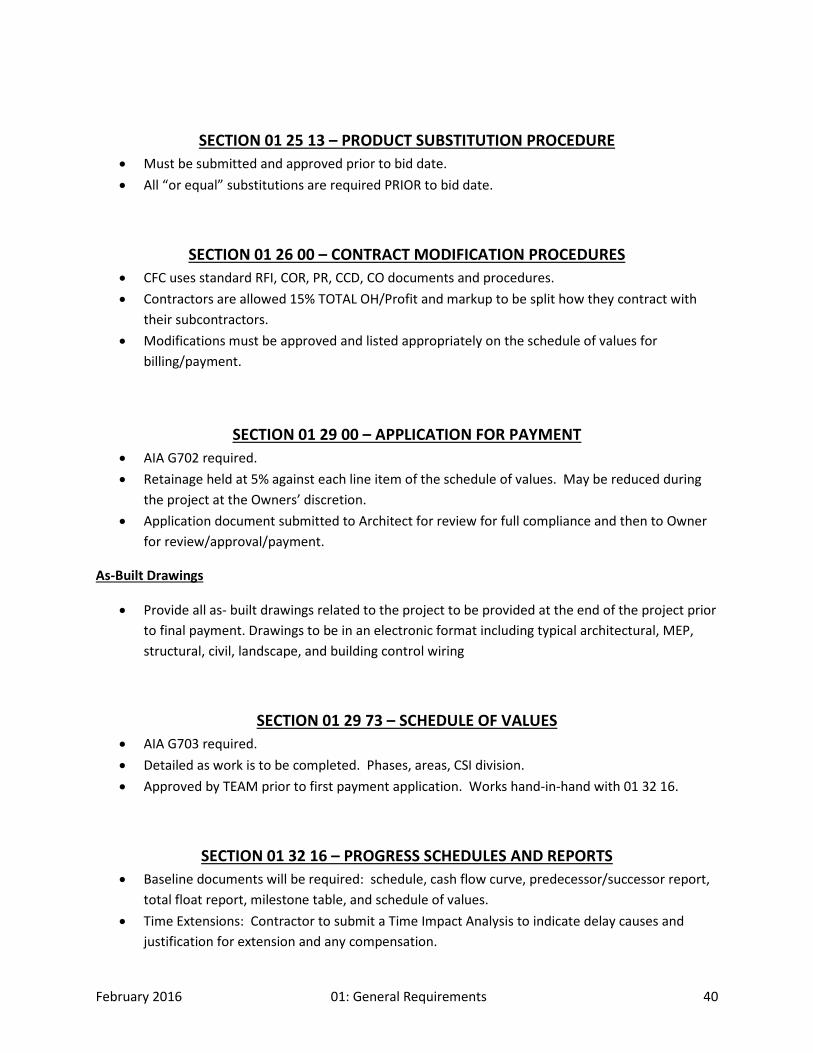
SECTION 01 25 13 – PRODUCT SUBSTITUTION PROCEDURE • Must be submitted and approved prior to bid date. • All “or equal” substitutions are required PRIOR to bid date.
SECTION 01 26 00 – CONTRACT MODIFICATION PROCEDURES • CFC uses standard RFI, COR, PR, CCD, CO documents and procedures. • Contractors are allowed 15% TOTAL OH/Profit and markup to be split how they contract with
their subcontractors. • Modifications must be approved and listed appropriately on the schedule of values for
billing/payment.
SECTION 01 29 00 – APPLICATION FOR PAYMENT • AIA G702 required. • Retainage held at 5% against each line item of the schedule of values. May be reduced during
the project at the Owners’ discretion. • Application document submitted to Architect for review for full compliance and then to Owner
for review/approval/payment.
As-Built Drawings
• Provide all as- built drawings related to the project to be provided at the end of the project prior to final payment. Drawings to be in an electronic format including typical architectural, MEP, structural, civil, landscape, and building control wiring
SECTION 01 29 73 – SCHEDULE OF VALUES • AIA G703 required. • Detailed as work is to be completed. Phases, areas, CSI division. • Approved by TEAM prior to first payment application. Works hand-in-hand with 01 32 16.
SECTION 01 32 16 – PROGRESS SCHEDULES AND REPORTS • Baseline documents will be required: schedule, cash flow curve, predecessor/successor report,
total float report, milestone table, and schedule of values. • Time Extensions: Contractor to submit a Time Impact Analysis to indicate delay causes and
justification for extension and any compensation.
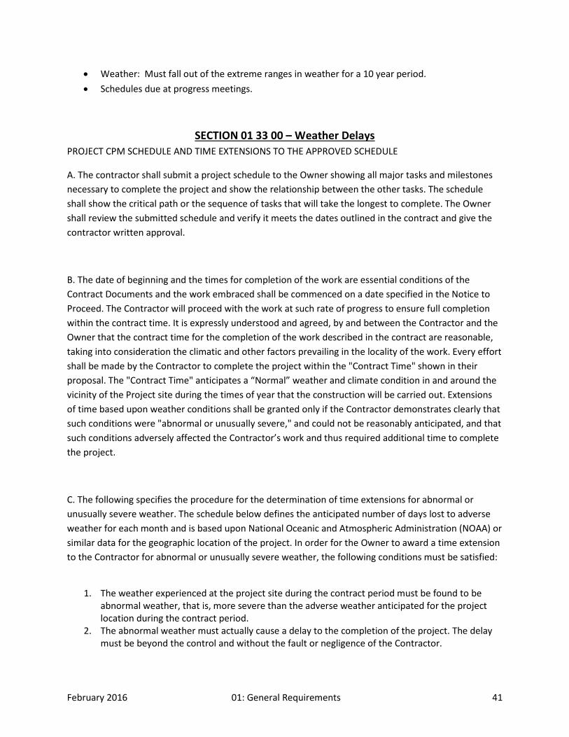
February 2016 01: General Requirements 41
• Weather: Must fall out of the extreme ranges in weather for a 10 year period. • Schedules due at progress meetings.
SECTION 01 33 00 – Weather Delays PROJECT CPM SCHEDULE AND TIME EXTENSIONS TO THE APPROVED SCHEDULE
A. The contractor shall submit a project schedule to the Owner showing all major tasks and milestones necessary to complete the project and show the relationship between the other tasks. The schedule shall show the critical path or the sequence of tasks that will take the longest to complete. The Owner shall review the submitted schedule and verify it meets the dates outlined in the contract and give the contractor written approval.
B. The date of beginning and the times for completion of the work are essential conditions of the Contract Documents and the work embraced shall be commenced on a date specified in the Notice to Proceed. The Contractor will proceed with the work at such rate of progress to ensure full completion within the contract time. It is expressly understood and agreed, by and between the Contractor and the Owner that the contract time for the completion of the work described in the contract are reasonable, taking into consideration the climatic and other factors prevailing in the locality of the work. Every effort shall be made by the Contractor to complete the project within the "Contract Time" shown in their proposal. The "Contract Time" anticipates a “Normal” weather and climate condition in and around the vicinity of the Project site during the times of year that the construction will be carried out. Extensions of time based upon weather conditions shall be granted only if the Contractor demonstrates clearly that such conditions were "abnormal or unusually severe," and could not be reasonably anticipated, and that such conditions adversely affected the Contractor’s work and thus required additional time to complete the project.
C. The following specifies the procedure for the determination of time extensions for abnormal or unusually severe weather. The schedule below defines the anticipated number of days lost to adverse weather for each month and is based upon National Oceanic and Atmospheric Administration (NOAA) or similar data for the geographic location of the project. In order for the Owner to award a time extension to the Contractor for abnormal or unusually severe weather, the following conditions must be satisfied:
1. The weather experienced at the project site during the contract period must be found to be
abnormal weather, that is, more severe than the adverse weather anticipated for the project location during the contract period.
2. The abnormal weather must actually cause a delay to the completion of the project. The delay must be beyond the control and without the fault or negligence of the Contractor.
February 2016 01: General Requirements 42
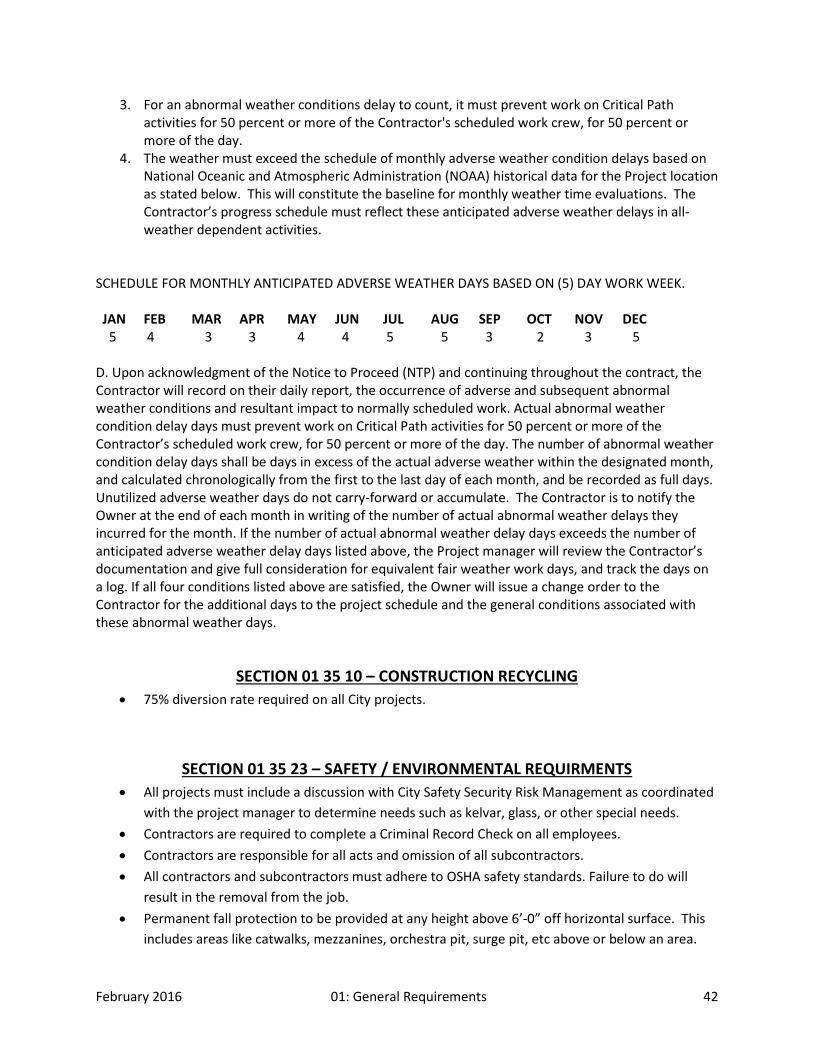
3. For an abnormal weather conditions delay to count, it must prevent work on Critical Path activities for 50 percent or more of the Contractor's scheduled work crew, for 50 percent or more of the day.
4. The weather must exceed the schedule of monthly adverse weather condition delays based on National Oceanic and Atmospheric Administration (NOAA) historical data for the Project location as stated below. This will constitute the baseline for monthly weather time evaluations. The Contractor’s progress schedule must reflect these anticipated adverse weather delays in all-weather dependent activities.
SCHEDULE FOR MONTHLY ANTICIPATED ADVERSE WEATHER DAYS BASED ON (5) DAY WORK WEEK. JAN FEB MAR APR MAY JUN JUL AUG SEP OCT NOV DEC 5 4 3 3 4 4 5 5 3 2 3 5 D. Upon acknowledgment of the Notice to Proceed (NTP) and continuing throughout the contract, the Contractor will record on their daily report, the occurrence of adverse and subsequent abnormal weather conditions and resultant impact to normally scheduled work. Actual abnormal weather condition delay days must prevent work on Critical Path activities for 50 percent or more of the Contractor’s scheduled work crew, for 50 percent or more of the day. The number of abnormal weather condition delay days shall be days in excess of the actual adverse weather within the designated month, and calculated chronologically from the first to the last day of each month, and be recorded as full days. Unutilized adverse weather days do not carry-forward or accumulate. The Contractor is to notify the Owner at the end of each month in writing of the number of actual abnormal weather delays they incurred for the month. If the number of actual abnormal weather delay days exceeds the number of anticipated adverse weather delay days listed above, the Project manager will review the Contractor’s documentation and give full consideration for equivalent fair weather work days, and track the days on a log. If all four conditions listed above are satisfied, the Owner will issue a change order to the Contractor for the additional days to the project schedule and the general conditions associated with these abnormal weather days.
SECTION 01 35 10 – CONSTRUCTION RECYCLING • 75% diversion rate required on all City projects.
SECTION 01 35 23 – SAFETY / ENVIRONMENTAL REQUIRMENTS • All projects must include a discussion with City Safety Security Risk Management as coordinated
with the project manager to determine needs such as kelvar, glass, or other special needs. • Contractors are required to complete a Criminal Record Check on all employees. • Contractors are responsible for all acts and omission of all subcontractors. • All contractors and subcontractors must adhere to OSHA safety standards. Failure to do will
result in the removal from the job. • Permanent fall protection to be provided at any height above 6’-0” off horizontal surface. This
includes areas like catwalks, mezzanines, orchestra pit, surge pit, etc above or below an area.

February 2016 01: General Requirements 43
Protection could include parapet wall, roof anchors, or other applicable method as determined by project manager and City team.
• All buildings will include Arc Flash study in accordance with NFPA 70E.
1. Prohibited Materials. The use of the following materials is prohibited on all projects:
• Products containing asbestos. • Products containing urea formaldehyde. • Products containing polychlorinated biphenyls. • Solder or flux containing more than 0.2 percent lead and domestic water pipe or pipe fittings
containing more than 8 percent lead. • Paint containing lead. • HBCD (Hexabromocyclododecane) – Commonly used in rigid insulation material as a fire-
retardant. • E.I.F.S.
2. Lead-Based Paint in Alteration or Demolition Projects. When alteration or demolition requires sanding, burning, welding or scraping painted surfaces, test the paint for lead content. If lead is found, implement the controls required by OSHA in 29 CFR 1926.62.
3. Recycled Materials. Architects and Engineers should use recycled materials to the maximum extent practical and economically viable within the project requirements.
4. Prior to occupancy, run a purge cycle of 100% outside air for several days.
SECTION 01 35 63 – SUSTAINABILITY CERTIFICATION PROJECT REQUIREMENTS
Part 1: General 1.01 Summary
A. CFC recognizes there are several existing and emerging green building standards that are applicable to government facilities. Our philosophy is to keep apprised of relevant standards and to determine which will be employed on a project-by-project basis. However, typical

February 2016 01: General Requirements 44
requirements are that all projects greater than 5,000 square feet will meet LEED Gold Certification based on the current rating system. The design of these buildings shall incorporate as many of green building principles (energy & water conservation, material selection, site location, etc.) as feasible to reduce building operating and maintenance costs along with minimizing environmental impacts. The minimum goal is 15 points; set target points with project manager and C.F.C. energy manager.
B. The costs and benefits will play into decisions about LEEDTM on an individual project basis. To maintain fiscal integrity of the project – if the payback from the additional cost of meeting Gold Certification over that of meeting Silver Certification is greater than ten years OR if the payback from the additional cost of meeting Gold Certification when compared to the local market cost for a similar building type is greater than ten years, then the City staff will recommend which level of LEED certification is appropriate for that particular project.
C. The CFC is targeting Net Zero Buildings for the future. By the year 2020 all new construction of city buildings will be Net Zero. The amount of energy a Net Zero Building uses on an annual basis is roughly equal to the amount of renewable energy created on the site.
D. CFC recognizes as these resources as potentially valuable design aides for future projects: 1. LEED™ 2. Green Globes 3. City of Fort Collins Green Building Code 4. City of Fort Collins Green Purchasing Guide 5. City Plan 6. AIA Integrated Design 7. Zero Energy Performance Index 8. If there are questions regarding the viability of additional design aides, approval before use
is required by the Director of Operation Services, assigned Project Manager, or the City Staff Architect.
E. The following features collectively represent a comprehensive, facility: 1. Sustainable site planning and landscape design 2. Use of renewable energy sources 3. High quality and energy efficient lighting 4. Energy efficient building shell 5. Energy efficient HVAC systems 6. Indoor environmental quality, including environmentally preferable building materials,
indoor air quality, acoustics and total moisture control 7. Water conservation 8. Security 9. Kitchen operations 10. Recycling and waste management 11. Construction waste reduction and recycling 12. Commissioning 13. Maintainability
1.02 Related Sections 1.03 Definitions 1.04 Submittals Required 1.05 Quality Assurance 1.06 Scheduling 1.07 Delivery, Storage, and Handling 1.08 Regulatory Requirements

February 2016 01: General Requirements 45
Part 2: Products 2.01 Manufacturers 2.02 Products
• Products will meet energy star, green seal, green guard, or equivalent, where applicable.
Part 3: Execution 3.01 Preparation 3.02 Installation 3.03 Cleaning and Protection
END OF SECTION 01 35 63
SECTION 01 43 26 – TESTING LABORATORY-AGENCY SERIVCES The Owner will employ and pay for services of an independent testing agency.
SECTION 01 45 00 – QUALITY CONTROL • Contractor to maintain daily reports, take regular photographs, maintain a project survey. • Contractor to GPS underground utilities. • Remodels – contractor to take extensive before/after video or pictures for future reference/
claims against either party for damages. • A Quality Assurance / Quality Control manual will be provided by the project manager to the
contractor.
SECTION 01 61 00 – COMMON PRODUCT REQUIREMENTS
Part 1: General 1.01 Summary 1.02 Related Sections 1.03 Definitions 1.04 Submittals Required
A. Material sample boards must be duplicated if they cannot be kept at the Owner’s office so that a set resides with the Facility Designer.

February 2016 01: General Requirements 46
B. All colors and finishes for both the interior and exterior must be submitted and approved prior to purchase. This includes landscaping materials.
1.05 Quality Assurance 1.06 Scheduling 1.07 Delivery, Storage, and Handling
A. Preference will be given to manufacturers that minimize/eliminate the use of product packaging.
1.08 Regulatory Requirements A. Observe environmental precautions based on conditions.
Part 2: Products 2.01 Manufacturers
A. Preference will be given to manufacturers who demonstrate sustainability practices in their own operations.
B. Preference given to manufacturers that take back excess and used material for recycling/reuse. Note that unless stated for a specific product, 3% of materials must be turned over to the City for attic stock.
C. All cleaning and maintenance instruction to be included in operations and maintenance chart (see 01.11.00).
2.02 Products
A. Source materials and products regionally whenever possible. Submit documentation of manufacturing locations and origins of materials for products manufactured and/or sourced from within 500 miles of the building site. Local materials have less energy cost and air pollution associated with their transportation and can help sustain a local economy.
B. Use recycled and/or rapidly renewable materials whenever possible. Submit invoices and listings of recycled and/or rapidly renewable materials that are used. 1. Indicate recycled content; indicate percentage of pre-consumer and post-consumer
recycled content per unit of product. 2. Select products with the highest recycled or rapidly renewable content that is readily
available C. Use salvaged and recovered products where feasible. Submit documentation showing the
origins of any salvaged products. D. Equipment: all purchased appliances/equipment must be Energy Star certified. E. All products installed in an interior location or location that can off-gas to the interior of the
building shall comply with the following VOC limits: 1. Plywood Adhesive: Water based contact cement with VOC content not to exceed 10 grams
per liter. 2. Total VOC for Upholstered Assembly: Not greater than 0.5 mg/m2/hr. 3. Formaldehyde Emission for Fabric: Not greater than 0.05 mg/m2/hr. 4. Formaldehyde Emission for Adhesive: Not greater than 0.05 mg/m2/hr. 5. 4 - Phenylcydohexene Emission: Not greater than 0.05 mg/m2/hr. 6. Styrene Emission: Not greater than 0.05 mg/m2/hr. 7. 2 Ethyl - 1 Hexanol Emission: Not greater than 3.00 mg/m2/hr. 8. General Adhesives: Water based adhesives with VOC content not to exceed 250 grams per
liter.

February 2016 01: General Requirements 47
9. Do not provide adhesives or accessories for wood flooring installation with a VOC content greater than 150 grams per liter (excluding finishing materials).
10. Finishing Material Adhesive: Water based adhesives with VOC content not to exceed 350 grams per liter.
F. Metals: 1. The following recycled content standards must be met for all metals applications, unless
otherwise noted: i. Steel Recycled Content: Minimum 23 percent post-consumer recycled content, or
minimum 7 percent pre-consumer recycled content at contractor’s option. ii. Aluminum Recycled Content: Minimum 5 percent post-consumer recycled content,
or minimum 20 percent pre-consumer recycled content at contractor’s option. iii. Copper Recycled Content: Minimum 5 percent post-consumer recycled content, or
minimum 20 percent pre-consumer recycled content at contractor’s option. G. Wood:
1. All wood-based materials and products shall be certified in accordance with the Forest Stewardship Council’s (FSC) Principles and Criteria. Submit FSC Chain of Custody Certification Numbers for all wood based materials and products used in the project.
2. Source wood from beetle damaged forests when possible. 3. All composite wood should not contain urea formaldehyde resin binders. Provide
appropriate documentation. 4. The following product alternatives should be applied in wood sheathing projects, and the
respective standards met, whenever feasible: i. Bio-based content for Engineered Wood Products
a. Interior Panels: Engineered products designed specifically for interior applications and providing a surface that is impact-, scratch-, and wear-resistant and that does not absorb or retain moisture. Provide minimum 55% bio-based content.
b. Structural Interior Panels: Engineered products designed for use in structural construction applications, including cabinetry, casework, paneling, and decorative panels. Provide minimum 89% bio-based content.
c. Structural Wall Panels: Engineered products designed for use in structural walls, curtain walls, floors and flat roofs in commercial buildings. Provide minimum 94% bio-based content.
ii. Fiberboard recycled content: a. Structural: Minimum 80 percent recycled content. b. Non-Structural: Minimum 100 percent post-consumer recycled content.
iii. Cellulose Honeycomb Panels: with 100 percent post-consumer recycled content. H. Plastic:
1. Plastic fabrications: i. Polyolefin-Based Plastic Lumber Decking Boards: Comply with ASTM D6662. ii. Extruded and Compression Molded Basic Shapes Made from Thermoplastic Polyester
(TPES): Comply with ASTM D6261. iii. Extruded, Compression Molded, and Injection Molded Basic Shapes of Poly(aryl ether
ketone) (PAEK): Comply with ASTM D6262. iv. Ultra-High-Molecular-Weight Polyethylene (UHMW-PE) Solid Plastic Shapes: Comply
with ASTM D6712. v. Compostable Plastics: Comply with ASTM D6400.
2. Plastic Lumber:
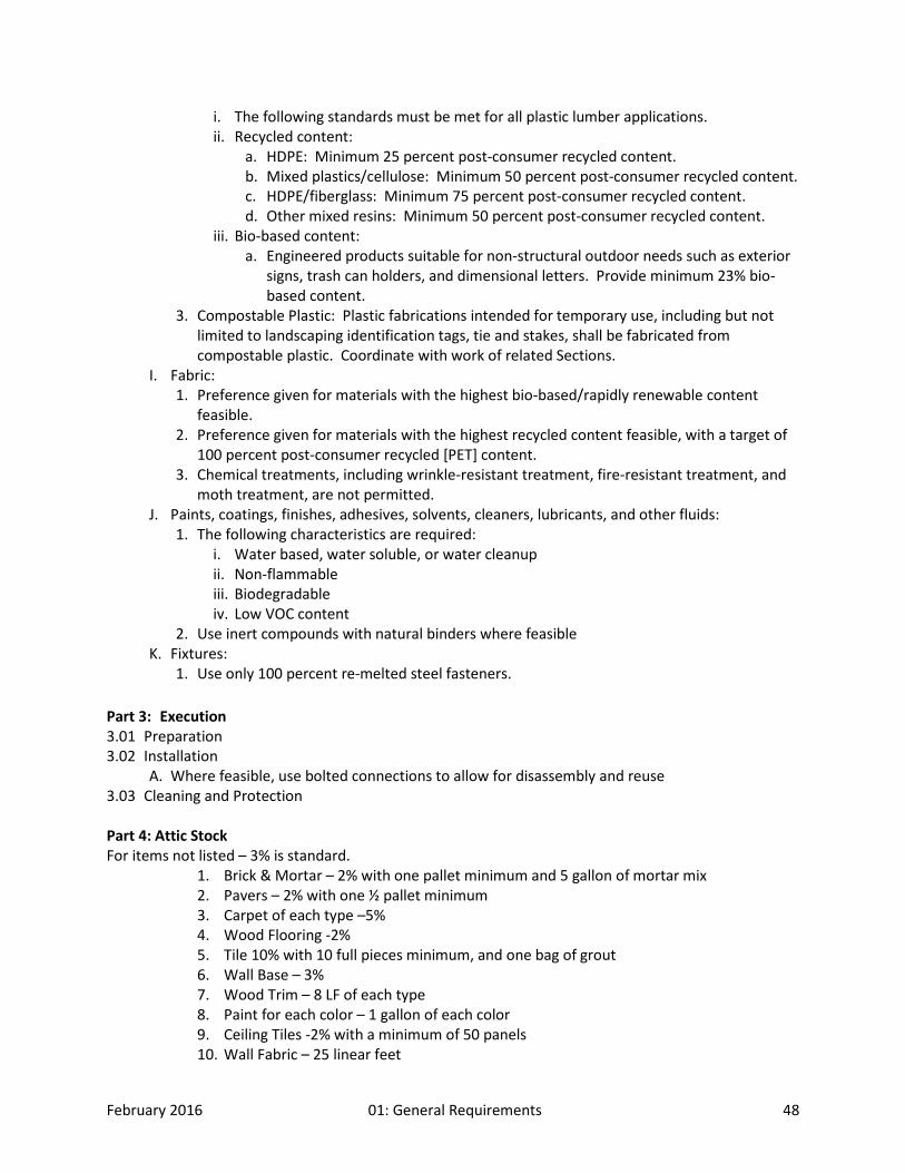
February 2016 01: General Requirements 48
i. The following standards must be met for all plastic lumber applications. ii. Recycled content:
a. HDPE: Minimum 25 percent post-consumer recycled content. b. Mixed plastics/cellulose: Minimum 50 percent post-consumer recycled content. c. HDPE/fiberglass: Minimum 75 percent post-consumer recycled content. d. Other mixed resins: Minimum 50 percent post-consumer recycled content.
iii. Bio-based content: a. Engineered products suitable for non-structural outdoor needs such as exterior
signs, trash can holders, and dimensional letters. Provide minimum 23% bio-based content.
3. Compostable Plastic: Plastic fabrications intended for temporary use, including but not limited to landscaping identification tags, tie and stakes, shall be fabricated from compostable plastic. Coordinate with work of related Sections.
I. Fabric: 1. Preference given for materials with the highest bio-based/rapidly renewable content
feasible. 2. Preference given for materials with the highest recycled content feasible, with a target of
100 percent post-consumer recycled [PET] content. 3. Chemical treatments, including wrinkle-resistant treatment, fire-resistant treatment, and
moth treatment, are not permitted. J. Paints, coatings, finishes, adhesives, solvents, cleaners, lubricants, and other fluids:
1. The following characteristics are required: i. Water based, water soluble, or water cleanup ii. Non-flammable iii. Biodegradable iv. Low VOC content
2. Use inert compounds with natural binders where feasible K. Fixtures:
1. Use only 100 percent re-melted steel fasteners.
Part 3: Execution 3.01 Preparation 3.02 Installation
A. Where feasible, use bolted connections to allow for disassembly and reuse 3.03 Cleaning and Protection Part 4: Attic Stock For items not listed – 3% is standard.
1. Brick & Mortar – 2% with one pallet minimum and 5 gallon of mortar mix 2. Pavers – 2% with one ½ pallet minimum 3. Carpet of each type –5% 4. Wood Flooring -2% 5. Tile 10% with 10 full pieces minimum, and one bag of grout 6. Wall Base – 3% 7. Wood Trim – 8 LF of each type 8. Paint for each color – 1 gallon of each color 9. Ceiling Tiles -2% with a minimum of 50 panels 10. Wall Fabric – 25 linear feet
February 2016 01: General Requirements 49
11. Sprinkler heads – 2 of each type 12. Light bulbs 13. Filters - Two sets of filters for filter separator, TWO SETS OF FILTER BAGS, TWO SETS OF
BELTS FOR EACH FAN. 14. VCT – not less than 2% 15. Valve wrenches – 2 for each type installed
END OF SECTION 01 61 00
SECTION 01 66 00 – NON-UTILIZATION OF ASBESTOS MATERIAL Asbestos is not to be used on any CFC projects. Contractor must certify all materials are free of asbestos containing materials.
SECTION 01 74 00 – CLEANING AND WASTE MANAGMENT
Part 1: General 1.01 Summary
A. Environmental Issues: Project requires special Site Waste Management Program and Stormwater management. 1. Waste Management Goals: A minimum of 75% of total Project waste shall be diverted
from landfill. 2. Provide documentation to show evidence that waste management, recycling, and reuse of
recyclable and reusable materials have been maximized. 3. Effect optimum control of solid wastes. 4. Prevent environmental pollution and damage. 5. Refer to the storm water procedures guide that will be provided by the project manager. A
copy of this guide must be kept on-site at all times for reference. 1.02 Related Sections 1.03 Definitions
A. Inert Fill: A permitted facility that accepts inert waste such as asphalt and concrete exclusively. B. Class III Landfill: A landfill that accepts non-hazardous waste such as household, commercial,
and industrial waste, including construction, remodeling, repair, and demolition operations. C. Construction and Demolition Waste: Includes solid wastes, such as building materials,
packaging, rubbish, debris, and rubble resulting from construction, remodeling, repair, and demolition operations. 1. Rubbish: Includes both combustible and noncombustible wastes, such as paper, boxes,
glass, crockery, metal and lumber scrap, tin cans, and bones. 2. Debris: Includes both combustible and noncombustible wastes, such as leaves and tree

February 2016 01: General Requirements 50
trimmings that result from construction or maintenance and repair work. D. Chemical Waste: Includes petroleum products, bituminous materials, salts, acids, alkalis,
herbicides, pesticides, organic chemicals and inorganic wastes. E. Sanitary Wastes:
1. Garbage: Refuse and scraps resulting from preparation, cooking, distribution, or consumption of food.
2. Sewage: Domestic sanitary sewage. 1.04 Submittals Required
A. Site Waste Management Program: Prior to commencement of Work, schedule and conduct meeting with CFC and Architect to discuss proposed Site Waste Management Program. 1. Develop mutual understanding relative to details of recycling, and rebate programs. 2. Prepare and submit a written and graphic Site Waste Management Program including, but
not limited to, the following: i. Indicate procedures to be implemented. ii. Estimate total Project waste to be generated and estimated cost of disposing of
Project waste in landfills. iii. Estimate total cubic yards of following waste categories to be diverted from landfill.
a. Clean dimensional wood, palette wood. b. Plywood, oriented strand board, and medium density fiberboard. c. Cardboard, paper, packaging. d. Other items as directed by CFC and Architect.
iv. Estimate amounts of following waste categories in appropriate units (weight, feet, square yards, gallons).
a. Metals. b. Gypsum board. c. Carpet. d. Paint. e. Other items as directed by CFC and Architect.
v. Submit permit or license and location of waste disposal areas. vi. Submit procedures for recycling/re-use program. vii. Submit procedures for rebate programs. viii. Revise and resubmit Site Waste Management Program.
a. Review of Contractor's Site Waste Management Program will not relieve Contractor of responsibility for control of pollutants and other environmental protection measures.
B. Submit summary of solid waste generated by Project with each application for progress payment. Include the following information: 1. Name of firm accepting the recovered materials or waste materials. 2. Specify type of facility (e.g. recycler, processor, Class III landfill, MRF). 3. Location of the facility. 4. Type of materials. 5. Net weights of each type of recovered material. 6. Date of delivery. 7. Value of the materials or tipping fee paid.
C. Prepare 3-ring binder with rebate information and product documentation as required for rebate programs; submit binder with final closeout submittals.
1.05 Quality Assurance 1.06 Recycling Program

February 2016 01: General Requirements 51
A. Recycling: Implement recycling program that includes separate collection of waste materials of following types as applicable to Project: 1. Asphalt. 2. Land clearing debris. 3. Soil. 4. Trees and shrubs. 5. Concrete and concrete blocks. 6. Brick and masonry materials. 7. Untreated lumber. 8. Clean dimensional wood and palette wood. 9. Plywood, oriented strand board, and medium density fiberboard. 10. Paper – bond. 11. Paper (e.g. newsprint). 12. Cardboard and paper packaging materials. 13. Plastics. 14. Rigid foam. 15. Insulation. 16. Ferrous metal. 17. Non-ferrous metals (e.g. copper, aluminum, etc.). 18. Glass. 19. Gypsum board (unpainted). 20. Carpet and pad. 21. Paint. 22. Beverage containers. 23. Plumbing fixtures. 24. Electrical fixtures and wires. 25. Others as appropriate.
B. Separation of Waste: Contractor and subcontractors are both required to separate recyclable materials into bins and to arrange for delivery of recyclable materials to recycling depot. Clearly label all recycling containers and list acceptable and unacceptable materials.
C. Handling: Keep materials free of dirt, adhesives, solvents, petroleum contamination, and other substances deleterious to recycling process. 1. Clean materials that are contaminated prior to placing in collection containers. 2. Arrange for collection by or delivery to appropriate recycling center or transfer station that
accepts construction and demolition waste for purpose of recycling. D. Participate in Re-Use Programs: Rebates, tax credits, and other savings obtained for recycled
or re-used materials shall accrue to Contractor. 1.07 Delivery, Storage, and Handling 1.08 Regulatory Requirements
Part 2: Products 2.01 Manufacturers 2.02 Products
Part 3: Execution 3.01 Preparation

February 2016 01: General Requirements 52
3.02 Installation 3.03 Cleaning and Protection
END OF SECTION 01 74 00
SECTION 01 81 13 – SUSTAINABLE DESIGN REQUIREMENTS
Part 1: General 1.01 Summary
A. The current LEED standard, with a gold rating, is the minimal threshold for sustainable requirements.
B. All CFC building projects should include the four basic and overlapping principles of Crime Prevention Through Environmental Design 1. Natural Surveillance - Create environments where there is significant opportunity
available for people engaged in their normal behavior to observe the space around them. Natural surveillance occurs by designing the placement of physical features, activities and people in such a way as to maximize visibility and foster positive social interaction among legitimate users of the space. Surveillance or the placing of legitimate ‘eyes on the street’ increases the perceived scrutiny and potential risk of offenders.
2. Natural Access Control - Selectively place entrances and exits, fencing, lighting, landscape and signs to control the flow of or to limit access, with the goal of promoting natural access control. Natural access control relies on both physical and psychological barriers to keep unauthorized persons out of a particular place if they do not have a legitimate reason for being there.
3. Natural Territorial Reinforcement - Utilize buildings, fences, pavement, signs, lighting and landscape to express ownership and define space, in order to facilitate natural territorial reinforcement. An environment designed to clearly delineate private space does two things. First, it creates a sense of ownership. Owners have vested interest and are more likely to challenge intruders to report them to the police. Second, the sense of owned space creates an environment where “strangers” or “intruders” stand out and are more easily identified.
4. Maintenance and Management - Maintenance and management need to be considered at the design stage, as the selection of material and finishes will impact on the types of maintenance requirements that can be sustained over time. This is related to the neighborhood’s sense of ‘pride of place’ and territorial reinforcement. The more dilapidated an area, the more likely it is to attract unwanted activities. The maintenance and ‘image’ of an area can have a major impact on whether it will become targeted.
C. Acoustics: Appropriate acoustical design is extremely important in all types of government facilities. The design consultant shall provide acoustical separation or isolate noise-generating activities, areas, and equipment. The spaces shall be designed with appropriate acoustical separations, acoustical absorption and reverberation time for all intended activities and the various acoustical volumes. As a minimum standard, the design of classrooms and other core learning spaces shall meet the requirements of ―Prerequisite #3, Minimum Acoustical Performance, LEED for New Construction and Major Renovations, 2007. Special attention shall
February 2016 01: General Requirements 53
be paid to providing vibration control and sound isolation for mechanical and electrical equipment, particularly mechanical rooftop units placed above occupied spaces.
D. Integrated Project Design and Whole Building Design 1. CFC believes the key to achieving a sustainable facility is to employ an integrated design
approach. This has been misinterpreted by some to mean putting together a good team that works well together. Integrated design extends beyond this meaning in two ways: 1. holistic, rather than systems-based design, and 2. collaboration that extends beyond the design team and beyond traditional perspectives. To fully incorporate the Integrated Design Process the following groups should be included at initial partnering meetings: Owner, Architect, Engineers, Contractor, Sustainability Consultant, Energy Modeling Consultant and any other applicable roles that will be utilized throughout the construction process.
2. The design process largely analyzed individual components and subsystems of each building, optimizing them separately. Whole building design not only looks at how materials, systems, and products of a building connect and overlap, but also considers how the building and its systems can be integrated with supporting systems on its site and in its community. A successful whole building design is a solution that is greater than the sum of its parts. The fundamental challenge of whole building design is to understand that all building systems are interdependent.
E. Building Performance goal values will be set on a case-by-case basis, but could include the following: 1. ENERGY STARTM rating 2. LEEDTM gold rating or better 3. Energy use (e.g., kBtu/ft2/yr) 4. Electric demand limits for peak periods 5. Water use and uniformity 6. Construction recycling diversion rate 7. Lighting load and electric plug load densities 8. Lighting and heating, ventilation, and air conditioning (HVAC) occupancy schedules 9. HVAC occupied/unoccupied set points
F. Each project shall set the following energy performance goals: 1. Exceed ASHRAE 90.1 by 60% 2. Energy Star score of 90 3. 35 kBtu/sq. ft./yr or better
G. Building Modeling
Introduction
The purpose of this document is to provide a structure for energy modeling for City of Fort Collins building design projects. For the purpose of this document, modeling refers to computer building simulation using hourly weather data.
Modeling can be used for a number of purposes within a project, such as providing information for the design process, setting targets, documentation for certifications (e.g. LEED), and post-occupancy

February 2016 01: General Requirements 54
tracking/reporting/operations. It is important for the design team to specify the purpose(s) for the model.
Modeling is one of many tools used in an integrated design process. It may not always be the appropriate tool for all building design projects or for all stages. For small projects and/or simple decisions it may be more cost effective and appropriate to use bin calculations or spreadsheet tools rather than an hourly computer simulation. For example, it may make more sense with a small building for which a few HVAC measures are being considered to use a spreadsheet bin analysis to examine the options rather than going to a more expensive and time-consuming hourly energy model. Thus, it is up to the design team to clarify which questions need to be answered and the appropriate tool to provide the answers.
It will be important for the modeler to work closely with the rest of the design team. Through an integrated design process the modeler should be kept aware of key design element changes affecting the model.
It will be important to set energy goals for the project. Options for doing so are detailed below.
Energy modeling is both a science and an art. At the stage in the design process when energy modeling is most useful, the building is not well defined. The modeler will have to make assumptions, in conjunction with the design team, in order to create the model. As the design develops and design decisions replace assumptions, the model will need to be refined so it represents the most current design. Throughout the modeling process, the model informs the design and the design informs the model. This dynamic will be active throughout the design process. As such it is important that the design team immediately inform the modeler as to changes in direction and that the modeler reacts quickly to requests for information from the design team. Timing is critical to making this process work. Modeling before there is enough information produces unreliable results. Waiting too long gives more reliable results that are of little use because the design has marched on. The modeling should be adequate to answer questions being presented and the results should be presented in enough detail to adequately inform decisions. Key modeling assumptions should be reported in enough detail to give the design team confidence in the results. Timely communication and quick turnaround between the design team and the modeler are important to making the process work well, especially early in the design process.
This activity must all be weighed against the modeling budget. Hourly simulation is a time-consuming and potentially expensive activity. The design team and modeler will have to strike a balance between providing enough information to make decisions and staying within budget.
Energy Modeler Contracting Guidelines
Ideally, the energy modeler should be brought into the design team during conceptual design or at the latest by the beginning of schematic design.

February 2016 01: General Requirements 55
The modeler will be hired by the City of Fort Collins and modeling activities and reporting will be coordinated through the City Project Manager in conjunction with the design team. The modeler must provide documentation that they are a certified ASHRAE Building Energy Modeling Professional.
Modeling RFP
The modeling RFP will include energy goals for the respective building(s) set by the City prior to the RFP. These goals will be set based on an evaluation of best practices for existing buildings of a similar type, Energy Star Target Finder, and desired percentage of points from the Energy and Atmosphere category of LEED. The energy goal should stretch the design team to be leading edge, but not so much as to be “bleeding edge” with too many untested concepts and technologies.
The RFP will also specify the type(s) of baseline models required. The reference (baseline) model will be dependent on the purpose of modeling. For the purpose of LEED certification, ASHRAE 90.1 Appendix G (version specified in LEED) should be used to define the reference model. For seeking funding from the Fort Collins Utilities Integrated Design Assistance Program (IDAP), the requirements in the current City of Fort Collins building code, with amendments, should be used to create the reference case. In some cases, the design team may want a baseline design model that is already above code. It is important to define the baseline(s) to be established in the modeling contract.
Programming/Pre-design/Conceptual Design
The objectives with regards to energy modeling prior to Schematic Design are to:
1. Set energy goals; 2. Establish a reference base case building model; 3. Evaluate passive elements such as shape, orientation, and fenestration/daylighting.
Requirements for developing the reference base case building model are given above. At this early stage, there may be a conceptual design for which a baseline reference model can be built. This model can be used to make changes in order to answer questions about passive elements of the building. At this stage, the model will have to be simple enough that the modeling budget is not significantly impacted and detailed enough that some basic design questions can be addressed. In some cases, it may be useful to use the model to help set energy goals (e.g. for unique building types).
Schematic Design
The objectives of Schematic Design (SD) with regards to energy modeling are to:
1. Optimize passive building elements, such as shape, orientation, envelope design (roof, wall, windows), insulation type and levels, mass, and daylighting schemes;

February 2016 01: General Requirements 56
2. Identify Energy Efficiency Measures (EEMs) with regards to HVAC, lighting and other building systems;
3. Select the most promising EEMs based on life-cycle cost. Packages of complimentary EEMs should be presented. Utility and other incentives should be evaluated in this assessment. Some measures that might be “thrown out” on initial analysis might make more sense when incentives are included.
4. Re-evaluate energy goals.
As the building design becomes more refined, it will be necessary to update the model. Prospective EEMs should be compared against the baseline individually and in combination to achieve the project energy goal.
The modeler will need to work closely with mechanical and electrical designers. The modeler will need to raise “red flags” when they see critical design issues emerging, especially for which quick decisions will need to be made.
SD reporting requirements –
Two formal SD reports are required, one at 50% SD and at 100% SD. The 50% report is one of the most critical junctures in the design process. Major design decisions are in the process of being made and it is important that the 50% SD report provides adequate information to make good decisions. It is also important for the design team to check modeling assumptions at this stage to be assured they reflect the intended design conditions. Required reporting elements are given in Appendix B.
In addition to the two formal SD reports, it is expected that several “mini-studies” be performed prior to 50% and 100% SD reports. The purpose of these mini-studies is to provide quick feedback to the design team on critical path items. The subjects of these mini-studies could be high-profile, critical-path EEMs for which decisions must be made quickly or evaluations of more subtle EEMs as individual items or in groups. The intent is to do enough modeling so that a go, no-go decision can be made on a particular design element to keep the design process moving.
Design Development
The objectives of Design Development (DD) with regards to energy modeling are to:
1. Refine definition and savings results for EEMs selected in SD; 2. Provide the owner with adequate information to select the final group of EEMs for the project; 3. Provide a comprehensive energy report.

February 2016 01: General Requirements 57
DD Reporting requirements –
Two formal DD reports are required, one at 50% DD and at 100% DD. Required reporting elements are given in Appendix B.
Construction Documents
The purpose of modeling during the CD stage is to clarify unanswered questions about the design/systems and to document the final design for use with LEED certification, incentives, and/or post-occupancy energy management.
CD Reporting requirements –
Two formal CD reports are required, one at 50% CD and at 100% CD. Required reporting elements are given in Appendix B.
An additional purpose of the CD models can be to help inform the sizing of the building transformer(s) to prevent the common practice of oversizing.
As-Built Drawings
Provide all as- built drawings related to the project to be provided at the end of the project prior to final payment. Drawings to be in an electronic format including typical architectural, MEP, structural, civil, landscape, and building control wiring.
Post Occupancy
In some cases there may be a request to adjust the model to reflect as-built conditions. The model may also be used in the Measurement and Verification (M&V) process to assess whether the actual performance reflects modeled performance. In cases where there is a mismatch it will be necessary to determine if it is due to an error in the modeling or something with the actual system.
Modeling Requirements
1. Modeling Tool
i. The modeling tool must be ASHRAE 140 certified 2. Inputs

February 2016 01: General Requirements 58
i. Weather input file – Fort Collins TMY3 ii. Utility rates:
a. Electric – Fort Collins Utilities Rates http://www.fcgov.com/utilities/business/rates/electric . See below required modeling details for electric rates.
b. Gas – Current Xcel Energy gas rates. Check with City Energy Manager for the appropriate rate.
c. Assume 3% utility annual increase. iii. Setpoints
a. For building setpoints, use 70°F for the occupied heating and 75°F for the occupied cooling. Unoccupied setback in heating mode is 65° and off for unoccupied cooling. The occupied/unoccupied times will be defined by the design team in conjunction with the Owner.
iv. Coincident Peak a. Use the load on the peak day for each month at the following hours to
determine the Coincident Peak value. Month Hour Ending
Jan 7:00 PM
Feb 7:00 PM
Mar 7:00 PM
Apr 9:00 PM
May 5:00 PM
Jun 5:00 PM
Jul 5:00 PM
Aug 5:00 PM
Sep 5:00 PM
Oct 7:00 PM
Nov 7:00 PM
Dec 7:00 PM
For explanations of Facility and Coincident Peaks, see http://www.fcgov.com/utilities/rts-bz-elctrc.php
v. Summer Peak Demand Savings a. When calculating Summer Peak Demand Savings, first find the peak hour in the
reference model and then use the load for the same day and hour in the proposed models to calculate savings. Summer Peak kW is defined as the
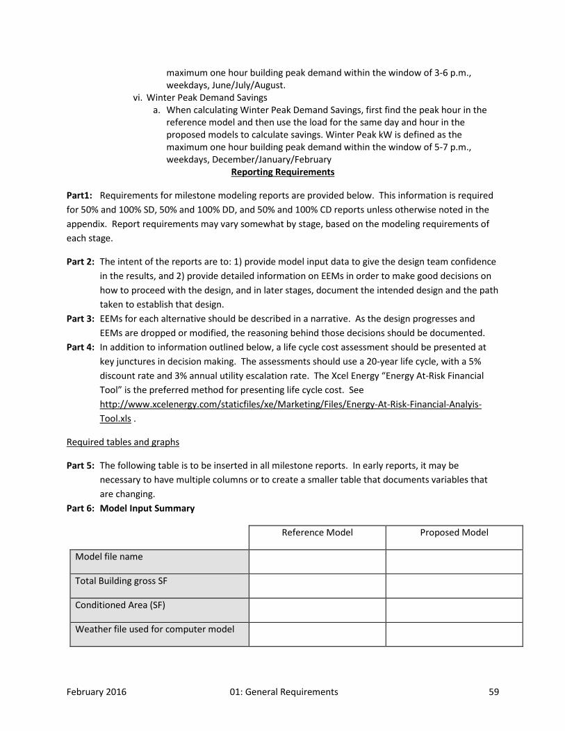
February 2016 01: General Requirements 59
maximum one hour building peak demand within the window of 3-6 p.m., weekdays, June/July/August.
vi. Winter Peak Demand Savings a. When calculating Winter Peak Demand Savings, first find the peak hour in the
reference model and then use the load for the same day and hour in the proposed models to calculate savings. Winter Peak kW is defined as the maximum one hour building peak demand within the window of 5-7 p.m., weekdays, December/January/February
Reporting Requirements
Part1: Requirements for milestone modeling reports are provided below. This information is required for 50% and 100% SD, 50% and 100% DD, and 50% and 100% CD reports unless otherwise noted in the appendix. Report requirements may vary somewhat by stage, based on the modeling requirements of each stage.
Part 2: The intent of the reports are to: 1) provide model input data to give the design team confidence in the results, and 2) provide detailed information on EEMs in order to make good decisions on how to proceed with the design, and in later stages, document the intended design and the path taken to establish that design.
Part 3: EEMs for each alternative should be described in a narrative. As the design progresses and EEMs are dropped or modified, the reasoning behind those decisions should be documented.
Part 4: In addition to information outlined below, a life cycle cost assessment should be presented at key junctures in decision making. The assessments should use a 20-year life cycle, with a 5% discount rate and 3% annual utility escalation rate. The Xcel Energy “Energy At-Risk Financial Tool” is the preferred method for presenting life cycle cost. See http://www.xcelenergy.com/staticfiles/xe/Marketing/Files/Energy-At-Risk-Financial-Analyis-Tool.xls .
Required tables and graphs
Part 5: The following table is to be inserted in all milestone reports. In early reports, it may be necessary to have multiple columns or to create a smaller table that documents variables that are changing.
Part 6: Model Input Summary
Reference Model Proposed Model
Model file name
Total Building gross SF
Conditioned Area (SF)
Weather file used for computer model
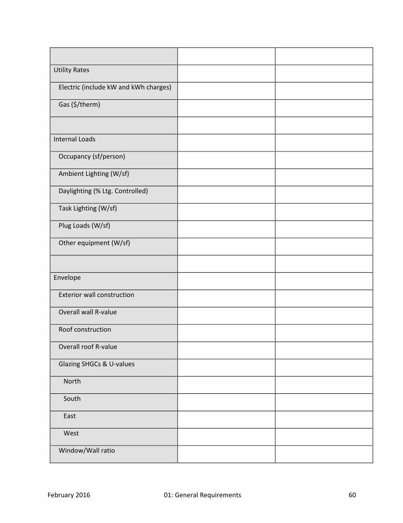
February 2016 01: General Requirements 60
Utility Rates
Electric (include kW and kWh charges)
Gas ($/therm)
Internal Loads
Occupancy (sf/person)
Ambient Lighting (W/sf)
Daylighting (% Ltg. Controlled)
Task Lighting (W/sf)
Plug Loads (W/sf)
Other equipment (W/sf)
Envelope
Exterior wall construction
Overall wall R-value
Roof construction
Overall roof R-value
Glazing SHGCs & U-values
North
South
East
West
Window/Wall ratio

February 2016 01: General Requirements 61
Infiltration (e.g. cfm/sf² of wall & roof area)
HVAC
Primary cooling system type (centrifugal chiller, DX, etc.)
Cooling Plant fuel type (electric, gas, etc.)
Primary Cooling efficiency (kW/ton)
Primary heating system type (condensing boiler, furnace, etc.)
Thermal storage (Y/N), type, capacity
Heating plant fuel type (gas, electric, etc.)
Heating plant efficiency
Secondary system type (VAV w/ electric reheat, constant volume, etc.)
Supply fan control (inlet vanes, VFD, etc.)
Return fan control
Supply air temperature
OA reset used (Yes/No)
Occupied Setpoints (Htg./Clg.)
Unoccupied Setpoints
Total supply CFM
Outside air CFM
Exhaust air CFM
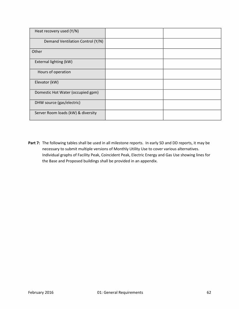
February 2016 01: General Requirements 62
Heat recovery used (Y/N)
Demand Ventilation Control (Y/N)
Other
External lighting (kW)
Hours of operation
Elevator (kW)
Domestic Hot Water (occupied gpm)
DHW source (gas/electric)
Server Room loads (kW) & diversity
Part 7: The following tables shall be used in all milestone reports. In early SD and DD reports, it may be necessary to submit multiple versions of Monthly Utility Use to cover various alternatives. Individual graphs of Facility Peak, Coincident Peak, Electric Energy and Gas Use showing lines for the Base and Proposed buildings shall be provided in an appendix.

February 2016 01: General Requirements 63
Model Utility Use Data
Energy Model EUI (kBtu/SF/yr)
Summer electric peak (kW)
Winter electric peak (kW)
Electric energy (kWh/yr)
Electric Cost ($/yr)
Gas (therms/yr)
Gas Cost ($/yr)
Total energy cost ($/yr)
Cost Savings ($/yr)
Incremental cost ($)
Reference Case
Alternate 1
Alternate 2
Alternate 3
…
Monthly Utility Use
Base Building Jan Feb Mar Apr May Jun Jul Aug Sep Oct Nov Dec Total
Facility Peak (kW)*
Coincident Peak (kW)*
Electric Energy (kWh)
Gas Use (Therms)
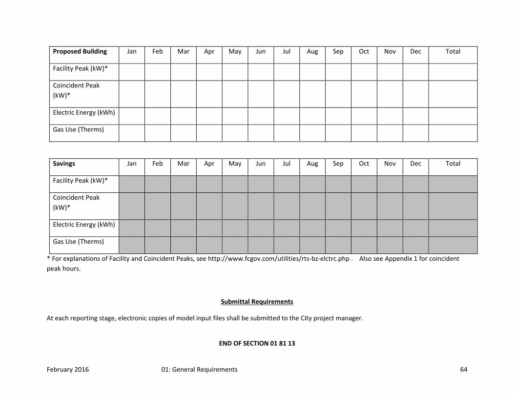
February 2016 01: General Requirements 64
Proposed Building Jan Feb Mar Apr May Jun Jul Aug Sep Oct Nov Dec Total
Facility Peak (kW)*
Coincident Peak (kW)*
Electric Energy (kWh)
Gas Use (Therms)
Savings Jan Feb Mar Apr May Jun Jul Aug Sep Oct Nov Dec Total
Facility Peak (kW)*
Coincident Peak (kW)*
Electric Energy (kWh)
Gas Use (Therms)
* For explanations of Facility and Coincident Peaks, see http://www.fcgov.com/utilities/rts-bz-elctrc.php . Also see Appendix 1 for coincident peak hours.
Submittal Requirements
At each reporting stage, electronic copies of model input files shall be submitted to the City project manager.
END OF SECTION 01 81 13

February 2016 01: General Requirements 65
SECTION 01 81 19 – INDOOR AIR QUALITY REQUIREMENTS
Part 1: General 1.01 Summary
A. Indoor Environmental and Air Quality: Materials are selected and processes specified, such as preconditioning and temporary ventilation, to maximize healthy indoor air quality. Cleaning, surface coating, and renewal or replacement of interior materials should be feasible with lowest practical use of toxic, irritating, or odorous compounds. Ventilation system design, construction, and commissioning ensure adequate outside air supply under all anticipated conditions of use. Documentation of system design assumptions is included in Project Manuals to enable building operators and management to use and modify the system as required to provide continued assurance of indoor air quality. Additionally, materials are selected to provide appropriate indoor environmental qualities such as good acoustics and lighting.
1.02 Related Sections 1.03 Definitions 1.04 Submittals Required
A. Indoor Air Quality (IAQ) Data: 1. Environmental Issues: Submit emission test data produced by acceptable testing
laboratory listed in Quality Assurance Article for materials as required in each specific Specification section.
i. Laboratory reports shall contain emissions test data on VOCs including total VOCs (TVOC), specific individual VOCs, formaldehyde and other aldehydes as described in this Specification Section.
ii. In special cases it may be necessary to identify other specific chemicals for listing based on known quantity present or on known odor, irritation or toxicity.
iii. Identify all VOCs emitted by each material as required in these Specifications. iv. Specific test conditions and requirements are set forth in this Section. For required
tests, submit documentation of sample acquisition, handling, and test specimen preparation, as well as test conditions, methods, and procedures. The tests consist of a ten-day conditioning period followed by a 96-h test period.
a. Samples collected during the test period at 24, 48, and 96 hours shall be analyzed for TVOC and formaldehyde.
b. VOC samples collected at 96 hours shall be identified and quantified for all compounds that are Chemicals of Concern on lists in Article 2.
1.05 Quality Assurance A. Acceptable Indoor Air Emissions Testing Laboratories:
1. Berkeley Analytical Associates; 815 Harbour Way South, Suite 6, Richmond, California 94804; telephone 510.236.2325; fax 510.236.2335; e-mail [email protected] .
2. Air Quality Sciences, Inc.; 1337 Capital Circle, Atlanta, Georgia 30067; telephone 770.933.0638; fax 770.933.0641; e-mail [email protected].
3. Other Laboratories: i. Selection of testing laboratories shall include assessment of prior experience in
conducting indoor source emissions tests. ii. Many laboratories participate in and are certified by American Industrial Hygiene
Association laboratory accreditation program. http://www.aiha.org/lists.html. a. These laboratories are accredited to do analysis for hazards at levels of concern
for industrial workplaces and not necessarily accredited, organized, or able to

February 2016 01: General Requirements 66
perform analysis for chemicals and particulate matter at concentrations of concern for indoor air.
iii. The proposed laboratory shall be an independent company or organization not related to manufacturer of product to be tested.
iv. Submit documentation on proposed laboratory for review and approval by CFC. B. Indoor Air Emissions Tests:
1. Provide environmental chamber test data from tests based on ASTM Standard D5116-97, Guide for Small Scale Environmental Chamber Determination of Organic Emissions from Indoor Materials/Products. (Refer to ASTM, Annual Book of Standards, Volume 11.03. West Conshohocken, PA: American Society for Testing and Materials. http://www.astm.org.)
2. Tests shall be conducted according to guidance contained in ASTM Standard D5116-97 on material test specimens pre-conditioned in clean air prior to testing.
i. Review test specimen collection, documentation, collection, preparation and shipping procedures with testing laboratory prior to preparing and shipping sample.
ii. Test specimens shall be packaged in the normal manner at the factory and shipped directly to testing laboratory by the manufacturer. For materials that are not packaged in convenient consumer units, alternate procedures to preserve the chemical integrity of the specimen are required. Obtain test laboratory procedure sheet covering the handling and shipping of materials. If such information is not provided by the laboratory, then wrap the specimen in a manner that will eliminate direct contact with air or packaging materials other than an inert air barrier such as foil or laboratory grade plastic sheet wrapping material.
iii. Conditioning: Condition all test specimens for ten days in clean air. Clean air should be free from the Chemicals of Concern listed in Article 2. Hold in clean vessels approximately the size of the test chambers and ventilated at the same air flow rate to be used in the test period. Suspend or place specimens on wire racks so that air freely circulates around all sides during the conditioning period. The air temperature and relative humidity during the conditioning period shall be 23±2ºC and 50±10% RH. Otherwise, the material must be held in an environmental chamber for the entire period.
iv. For wet-applied products and material assemblies, a realistic test specimen shall be prepared using the substrate material on which it will be applied in the building. Alternately, it may be necessary to use a substrate material that closely simulates the actual building substrate.
v. For material assemblies (e.g., floor and wall systems where the finish material is placed over a substrate, either with or without the use of adhesives), individual components of the assembly system shall be tested separately. If all components meet the emissions criteria established herein, no further testing shall be required. For assemblies where one component, such as a floor or wall covering adhesive, does not meet the criteria, the assembled system may be tested with specimen preparation following the manufacturer’s recommended procedures for application of wet components and assembly of the system. If there is a difference between the manufacturers’ recommended procedures and procedures required by the project specifications, the project specifications shall be followed.
vi. Wall and other types of paints shall be tested according to the specifications for the particular material. For example, if two coats are to be applied over a primer coat, then the test specimen shall be prepared accordingly, dried between coats per

February 2016 01: General Requirements 67
manufacturer’s label instructions, and tested as a complete assembly after required conditioning. The total quantity of paint applied shall be reported based on the weight of the assembly immediately before and after the application of each coat.
3. The maximum concentration for any chemical emitted at 96 hours in emissions tests shall not result in a modeled indoor air concentration greater than ½ the chronic inhalation REL concentration of California Office of Environmental Health Hazard Assessment (OEHHA) Chronic Reference Exposure Limit (REL), with the exception of formaldehyde, which is discussed separately below.
4. Formaldehyde: No single product shall contribute more than one half (½) the OEHHA staff recommended indoor air limit of 33 μg/m3 (27 ppb) for formaldehyde. The calculated concentration of formaldehyde shall not exceed 16.5 μg/m3. Same modeling procedure as described above shall be used for formaldehyde. This concentration limit shall apply to all building and occupancy types.
5. Construction adhesives used in Work shall comply with following requirement: no component present in adhesive at more than 1% of total mass of adhesive shall be a carcinogen or reproductive toxicant as defined in the lists in this specification section.
6. Provide calculations of modeled concentrations based on emissions test results. i. Calculations shall be submitted with all other documentation. This requires the
calculation of emission factors based on emissions tests, then application of the emission factors, product loading factors in the building, and building parameters in a steady state mass-balance model. The model assumes zero outdoor concentrations, perfect mixing and no sink effects. Alternatively, follow procedures in ASTM D5116-97 and submit assumptions and calculations.
ii. The concentration of a compound in the building shall be calculated using the following Equation;
Concentration = (Emission factor) * (Loading factor)
(Air change rate)
For this equation, the units are: μg/m3 = (μg/m2 hr) * (m2/m3)
(h-1) This can be simplified as follows: Concentration = Emission rate Air change rate Note that the weekly average air change rate must be used in the calculations of concentrations of contaminants.
iii. Calculation of emission rate. Determine the emission rate by multiplying the emission factor by the amount of the material to be used in the building or air handler zone being evaluated. Multiply the emission factor by the area of the material in the building zone being assessed. Note that in some cases a length or mass may be the appropriate unit for emission factor that must then be multiplied by the length or mass of the emission source.
iv. Provide to the laboratory the total area of the zone being assessed by consulting the
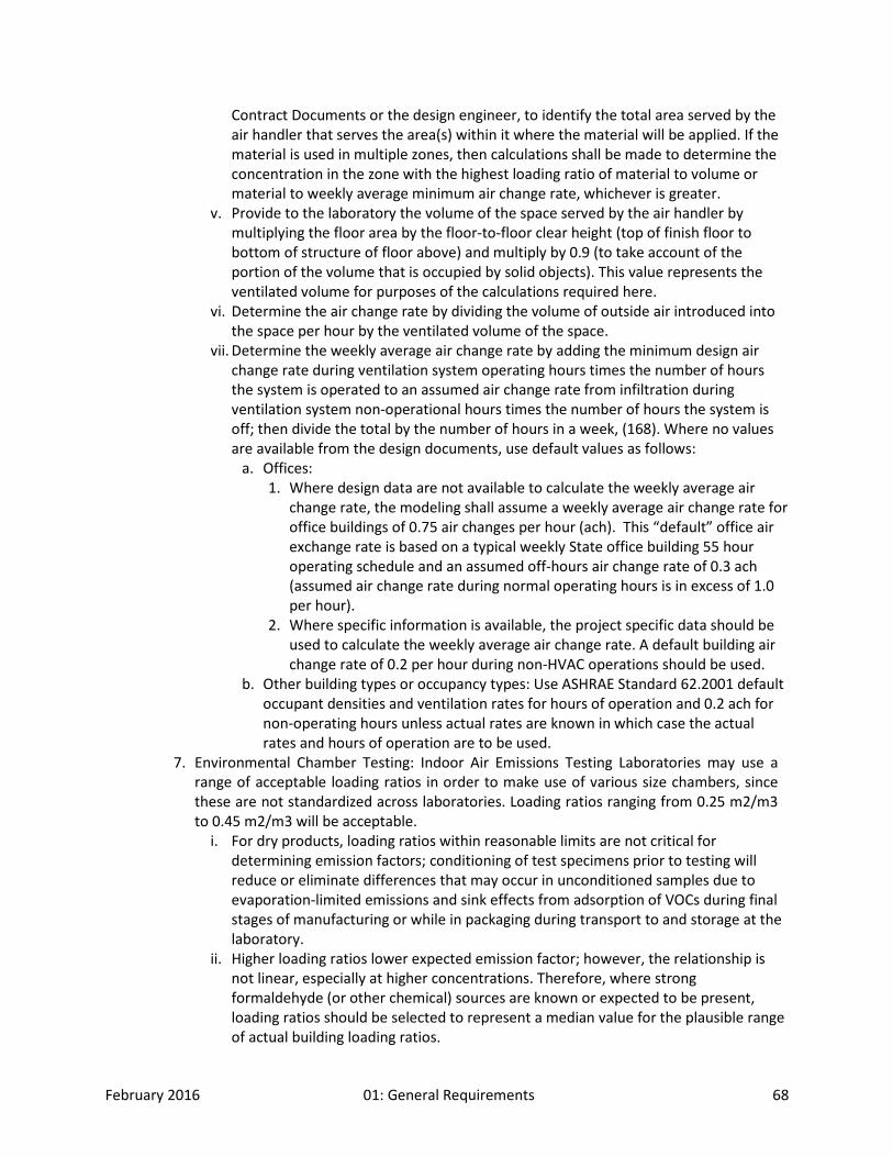
February 2016 01: General Requirements 68
Contract Documents or the design engineer, to identify the total area served by the air handler that serves the area(s) within it where the material will be applied. If the material is used in multiple zones, then calculations shall be made to determine the concentration in the zone with the highest loading ratio of material to volume or material to weekly average minimum air change rate, whichever is greater.
v. Provide to the laboratory the volume of the space served by the air handler by multiplying the floor area by the floor-to-floor clear height (top of finish floor to bottom of structure of floor above) and multiply by 0.9 (to take account of the portion of the volume that is occupied by solid objects). This value represents the ventilated volume for purposes of the calculations required here.
vi. Determine the air change rate by dividing the volume of outside air introduced into the space per hour by the ventilated volume of the space.
vii. Determine the weekly average air change rate by adding the minimum design air change rate during ventilation system operating hours times the number of hours the system is operated to an assumed air change rate from infiltration during ventilation system non-operational hours times the number of hours the system is off; then divide the total by the number of hours in a week, (168). Where no values are available from the design documents, use default values as follows:
a. Offices: 1. Where design data are not available to calculate the weekly average air
change rate, the modeling shall assume a weekly average air change rate for office buildings of 0.75 air changes per hour (ach). This “default” office air exchange rate is based on a typical weekly State office building 55 hour operating schedule and an assumed off-hours air change rate of 0.3 ach (assumed air change rate during normal operating hours is in excess of 1.0 per hour).
2. Where specific information is available, the project specific data should be used to calculate the weekly average air change rate. A default building air change rate of 0.2 per hour during non-HVAC operations should be used.
b. Other building types or occupancy types: Use ASHRAE Standard 62.2001 default occupant densities and ventilation rates for hours of operation and 0.2 ach for non-operating hours unless actual rates are known in which case the actual rates and hours of operation are to be used.
7. Environmental Chamber Testing: Indoor Air Emissions Testing Laboratories may use a range of acceptable loading ratios in order to make use of various size chambers, since these are not standardized across laboratories. Loading ratios ranging from 0.25 m2/m3 to 0.45 m2/m3 will be acceptable.
i. For dry products, loading ratios within reasonable limits are not critical for determining emission factors; conditioning of test specimens prior to testing will reduce or eliminate differences that may occur in unconditioned samples due to evaporation-limited emissions and sink effects from adsorption of VOCs during final stages of manufacturing or while in packaging during transport to and storage at the laboratory.
ii. Higher loading ratios lower expected emission factor; however, the relationship is not linear, especially at higher concentrations. Therefore, where strong formaldehyde (or other chemical) sources are known or expected to be present, loading ratios should be selected to represent a median value for the plausible range of actual building loading ratios.

February 2016 01: General Requirements 69
iii. Loading ratios used shall be included in test report. iv. Contractors shall provide to product manufacturers information on actual quantity of
material to be used in Project. The product manufacturers will then forward this information to Indoor Air Emissions Testing Laboratory so loading ratios can be adjusted toward actual loading ratio of Project. However, for most low-emitting materials used in construction, actual loading ratio will not significantly affect emission rates except for strong formaldehyde sources, primarily products using urea-formaldehyde resins.
8. Sample Preparation Requirements: i. Substrates for environmental chamber emissions tests of individual products or
materials (materials tested separately): a. Dry solid sheet type products: b. Sheet stainless steel or aluminum tray to provide tight fit at edges and reduce
emissions from edge of material specimen. If material does not fit very snugly, then use aluminized, low-emitting, clean room tape to seal edges. Dry fabric type products: 1. No substrate necessary.
c. Wet products such as adhesives and sealers: 1. Sheet stainless steel, aluminum, or glass unless product is to be applied to
gypsum board or other highly absorbent material. If substrate is a highly absorbent material, use a sample the substrate pre-conditioned for 24 hours to the temperature and humidity of the test chamber.
d. Substrates for specific products: 1. Wood products: sample to be suspended or supported in chamber with all
edges exposed and no edge masking. 2. Gypsum Board: no substrate (testing required ONLY if recycled content
gypsum board or if water resistant types are used). 3. Acoustical Ceiling Panels: no substrate, sample to be suspended or
supported in chamber with no edge masking. 4. Resilient flooring: stainless steel tray, fitted tightly so that only the upper
surface is exposed. Alternately, cover back of flooring with sheet stainless steel and seal edges with low-VOC emitting aluminized clean room tape so only wear surface of flooring is exposed.
5. Carpet Tile and Broadloom Carpet: stainless steel tray, fitted tightly so that only the upper surface is exposed.
6. Satin Paints: 5/8" gypsum board. 7. Semi-gloss paints: Where applied to metal, use sheet stainless steel. Where
applied to gypsum board, use gypsum board conditioned as described in subsection c below.
8. Joint Sealers: Steel channel 0.64 cm by 0.64 cm by 25.4 cm Channel shall be filled with sealant.
ii. Substrates for environmental chamber emissions tests of assemblies of products or materials (materials tested in an assembly):
a. Laminates or wood veneers applied with adhesives (Section 06060): Medium density fiberboard (MDF).
b. Resilient flooring applied with adhesives (Section 09650): Sheet stainless steel or glass plate.
c. Broadloom Carpet applied with adhesives and adhesives (Section 09680): Sheet

February 2016 01: General Requirements 70
stainless steel or glass plate. d. Wall Coverings applied with adhesives (Section 09950 Series): 5/8” gypsum
board. Prior to preparation of the test specimen, Gypsum board substrate shall be pre-conditioned for at least 24 hours at 23 ± 2oC and 50 ± 10% RH while ventilated with clean air.
iii. Protocol for Paint Testing: Preparation and handling of paint test specimen. e. Satin Paints: f. Apply paints to 5/8" thick gypsum board. Hold Gypsum board substrate for at
least 24 hours at 23 ± 2oC and 50 ± 10% RH while ventilated with clean air. Accurately weigh substrate just prior to painting, mask borders to avoid paint dripping on edges and leave center area for paint. Alternative approaches to protecting the edges are acceptable and shall be reported if used. 1. Apply paint using standardized roller procedure that simulates application
of paint in building. For most wall paint applications use a 4” wide 3/8” nap roller intended for smooth surfaces.
2. Stir paint in container and transfer 100 mL of paint to heavy-duty aluminum foil disposable tray.
3. Saturate roller cover with paint by running back and forth in tray. 4. Apply paint to substrate using four strokes, two in vertical direction and two
in horizontal direction, so entire area is uniformly covered. 5. Remove tape from substrate and re-weigh substrate. 6. Difference in weight determines amount of applied paint and coverage in
grams of wet paint per square meter of substrate surface. 7. Place substrate on 6" by 6" piece of sheet stainless steel to cover entirely
the back surface. Attach substrate to stainless steel with strips of low VOC aluminized clean room tape so only painted surface is exposed. For a blank specimen, similarly prepare an unpainted piece of gypsum. Alternate procedures to cover unpainted surfaces of gypsum board may be used and must be adequately described in the laboratory report if used.
8. Place sample in conditioning environment immediately and hold for ten days.
9. Where multiple coats, which may include primer, are being tested, apply paints and follow manufacturers’ instructions for drying time between coats. Report weight of test specimen prior to and after each coat of paint is applied. Hold specimen in conditioning environment between coats. The ten-day conditioning period begins after application of final coat. Apply semi-gloss paint to clean steel sheet following same procedure as above for “satin paints.” No tape should be used. Sheet should be weighed immediately before and after painting.
9. Chemical Analyses: i. VOC Analysis: Make multi-point calibrations using pure compounds whenever such
compounds are available from commercial suppliers (such as Aldrich Chemical Company, Sigma Aldrich). Quantitative analyses performed using surrogate compounds shall be indicated in reported test results. Identify EPA and ASTM standard methods and practices, and testing laboratory calibration procedures, which should include a calibration at least once every three (3) months.
ii. Formaldehyde and Acetaldehyde Analysis: Formaldehyde and Acetaldehyde analysis shall be performed following ASTM Standard D 5197 "Standard Test Method for
February 2016 01: General Requirements 71
Formaldehyde and other Carbonyl Compounds in Air (Active Sampler Methodology)" 10. Reporting Requirements: In addition to reporting requirement stated elsewhere in
Specifications, reports shall include: (a) all compounds emitted from sample that are on the most recent Chronic Reference Exposure Level list as published by the California Office of Environmental Health Hazard Assessment and listed in their website at http://www.oehha.org/air/chronic_rels/allChrels.html, (b) all compounds on the California Proposition 65 list, and (c) all compounds on the California Toxic Air Contaminant list. In addition, the ten most abundant compounds shall be reported separately if not listed on any of these lists. For these compounds, report following:
i. Measured chamber concentrations at each required time point. ii. Calculated emission factors. iii. Calculated building concentrations and assumptions used to make calculation.
1.06 Scheduling 1.07 Delivery, Storage, and Handling 1.08 Regulatory Requirements
Part 2: Products 2.01 Manufacturers 2.02 Products
Part 3: Execution 3.01 Preparation 3.02 Installation 3.03 Cleaning and Protection
END OF SECTION 01 81 19
SECTION 01 90 00 – LIFE CYCLE COSTING Part 1: General
1.01 Summary
1. Life cycle costing is an important analysis used in the selection of systems that generate significant operating costs and/or replacement costs.
In designs for new buildings and major alterations, life cycle cost analyses shall be performed to assist in the selection of various systems and is required in the A/E’s scope of work. An example of an HVAC life cycle cost analysis is provided in Appendix B-1.
February 2016 01: General Requirements 72
2. Cost Elements: The life cycle cost analysis should use present value calculations.
It is important to note that present value calculations are only meaningful for design decision comparisons. Present value costs should never be used to make budgetary projections of actual costs.
Note: The following terms are used within present value life cycle cost formula:
FV = future value
PV = present value
TV = today’s value
D = real discount rate
E = real growth escalation rate (the differential escalation rate that exists after removing the influence of general inflation)
N = number of years to occurrence or the analysis period, as appropriate
3. Sustainability: An additional consideration to L.C.C. is the material’s environmental appropriateness and ecological sensitivity when analyzed on a cradle-to-grave basis.
The complete life-cycle energy, environmental, and waste implications of each building material must be examined. This cradle-to-grave analysis is the tracing of a material or product, and its by-products, from its initial source availability and extraction through refinement, fabrication, treatment and additives, transportation, use, and eventual reuse or disposal. This tracing must include the tabulation of energy consumed and the environmental impacts of each action and material.
4. The following general design objectives shall be considered and utilized where feasible when designing or planning the construction of new buildings or renovation of existing buildings.
a. Reduce environmental impact through respect for natural systems and the ecology of the site by considering storm water management & pollution prevention, storm water detention & retention, natural solar shading, incorporating renewable resource use and other innovative environmental impact reduction designs.

February 2016 01: General Requirements 73
b. Ensure energy efficiency by incorporating the use of sustainable energy sources, reduce energy costs reduction strategies through building design, maximizing the use of natural day light, daylighting, the use of energy efficient artificial lighting, passive heating/cooling and other cost effective energy conservation designs.
c. Ensuring resource conservation when considering the use of land, materials & building in the most efficient & effective manner through the use of pre-used construction materials, use of construction materials made from recycled materials, the minimizing construction waste, the use of water minimizing fixtures and other cost effective source conservation designs and activities.
d. Ensure the health & well-being of the building occupants & visitors through the use of low VOC materials (paint, cleaners, etc.), efficient HVAC design with fresh air to maintain the recommended CO2 levels and other indoor air quality and indoor environmental enhancing designs and activities.
e. Strive to incorporate all the above sustainable approaches to achieve a comprehensive and holistic environmentally sustainable facility.
Factors Considered in Choosing Products and Materials Energy efficiency Energy-efficient production methods
Energy-efficient use Use of renewable source of energy
Resource responsibility Minimal need for other materials Lower maintenance, durability Efficient use of resource material Recycled content Recyclable
Social/Public health responsibility Avoidance of harmful chemicals in production Reduction of off-gassing Avoidance of harmful chemicals in disposal And reuse
Economic/functional responsibility Cost effectiveness Availability Acceptability
Qualities of supplier on manufacturer Local resource Local manufacture Local economic benefit In-house environmental programs

February 2016 01: General Requirements 74
SAMPLE LIFE CYCLE COST ANALYSIS
Building Name: Building No:
Project Name: Project No:
Concept Title:
Analysis Period: 25 Years Real Disc. Rate: 4.7%
Energy Savings (2) Building Energy Use: 1,010,000 KJ/SM/YR
Cost Elements Baselines Alternate Difference
a. Construction Cost $2,979,961 $2,997,613
b. Contingencies
c. Design Fee + Award Costs N.A. N.A.
d. Construction Supervision N.A. N.A.
e. Moving Costs N.A. N.A.
f. Relocation Costs N.A. N.A.
g. Initial Training Costs N.A. N.A.
h. Other First Costs $309,773 $311,607
(1) Subtotal (add above) $3,289,734 $3,309,220 w. -$19,486
i. TV Energy Cost/Year
j. PV All Energy Costs $3,215,089 $3,108,595 y. $106,494
k. TV Maintenance Cost/Year $26,000 $26,000
l. PV All Maintenance Costs $329,101 $329,101
m. TV Service Cost/Year
n. PV Service Cost

February 2016 01: General Requirements 75
Another option is the Life Cycle Costing Analysis could be performed using the latest version of the Building Life Cycle Cost (BLCC) computer program developed by the National Institute of Standards and Technology (NIST).
(2) Subtotal ( j + l + n ) $3,544,190 $3,437,696 v. $106,494
o. TV Future Replacements
p. PV All Future Replacements
$111,415 $111,415
q. TV Salvage Value $0 $0
r. PV Salvage Value $0 $0
s. Depreciated Residual Worth
t. PV Residual Worth $0 $0
(3) Subtotal (p - r or t ) $111,415 $111,415 x. $0
TOTAL LIFE CYCLE COST
( 1 + 2 + 3 ) $6,945,339 $6,858,331 u. $87,008
Indicies:
Net Savings (NS = u): $87,008 Savings to Investment Ratio (SIR = v / ( w + x ) ): 5.47
For Energy Conservation Projects: ESIR = z / w ECSR = y / w

February 2016 01: General Requirements 76
SECTION 01 91 00 – COMMISSIONING Part 1: General 1.01 Summary
A. THIS SECTION IS WRITTEN FOR LARGER PROJECTS AND NEW BUILDINGS. THE INTENT IS CLEAR FOR ALL CFC PROJECTS. HOWEVER, THE REQUIREMENTS HEREIN MAY BE ALTERED TO FIT THE INDIVIDUAL PROJECT IT IS TO BE USED ON.
B. Commissioning is a comprehensive and systematic process to verify that the building systems perform as designed to meet the owner’s requirements. Commissioning during the construction, acceptance, and warranty phases is intended to achieve the following specific objectives: Verify and document that equipment is installed and started per manufacturer’s recommendations and to industry accepted minimum standards. 1. Verify and document that equipment and systems receive complete operational checkout
by installing contractors. 2. Verify and document equipment and system performance. 3. Verify the completeness of operations and maintenance materials. 4. Ensure that the owner’s operating personnel are adequately trained on the operation and
maintenance of building equipment. i. The commissioning process does not take away from or reduce the responsibility of
the system designers or installing contractors to provide a finished and fully functioning product.
ii. The Commissioning Authority is hired by and under contract with the owner. The general contractor that is awarded the project shall not include the cost of the Commissioning Authority in their price. The general contractor (and their sub-contractors) shall include cost for their involvement in the commissioning process including demonstration of installed equipment to the commissioning team members during the acceptance portion of the project, and other responsibilities as described in the specification.
C. The design intent of the building enclosure is to provide exterior floor, wall, and roof assemblies which prevent uncontrolled air and water infiltration and include products and assemblies that are technically sound, durable and serviceable. This section includes requirements for non-structural commissioning of the building enclosure, including, but not limited to the following:
1. Below-grade construction, including foundation walls and slabs-on-grade. 2. Above-grade construction, including: exterior wall materials and assemblies; steep-slope
and low-slope roofing, outdoor plazas, planters and plaza paving systems and assemblies over occupied space, as well as glazed window, curtain wall and sloped glazing systems.
3. Interface conditions (flashings, expansion joints, sealant) between each of the materials, components and systems that comprise the above and below-grade building exterior enclosure.
4. Thermal and Moisture Protection standards to meet or exceed the City of Fort Collins Green Building Code. See Appendix C-Bldg. Envelope and Air Barrier Dwg. Appendix D-Thermal Bridging.
D. The purpose of the building enclosure commissioning (BECx) is to provide a process for independent, third-party verification that the installed performance of the building enclosure meets or exceeds the minimum performance requirements set forth by the Contract Documents for this project. The materials, components, systems, and assemblies that

February 2016 01: General Requirements 77
comprise the above and below-grade building exterior enclosure will be evaluated and tested as outlined in this Section, as well as in accordance with each of the technical Sections associated with the design and construction of the building enclosure.
1.02 Related Sections 1.03 Definitions
A. Commissioning Team. Commissioning Authority (CA), the Owner’s Representative (PM), the General Contractor (GC or Contractor), the architect and design engineers (A/E), the Mechanical Contractor (MC), the Electrical Contractor (EC), the Controls Contractor (CC), the owner’s maintenance staff, and any other installing subcontractors or suppliers of equipment.
B. The responsibilities of various parties in the commissioning process are provided in this section. The responsibilities of the mechanical contractor, TAB and controls contractor and those of the electrical contractor are in their respective divisions. It is noted that the services for the Project Manager, Design Team, and Commissioning Authority are not provided for in this contract. That is, the Contractor is not responsible for providing their services. Their responsibilities are listed here to clarify the commissioning process. 1. All Parties
i. Attend commissioning scoping meeting and additional coordination meetings, as necessary.
ii. Preliminary HVAC design meeting (required); include the energy model team. 2. Architect (A/E) – Architect of Record
i. Construction and Acceptance Phase a. Attend the commissioning scoping meeting and selected commissioning team
meetings. b. Provide design narrative documentation requested by the CA. c. Coordinate resolution of system deficiencies identified during commissioning,
according to the contract documents.
3. Mechanical and Electrical Designers/Engineers (A/E) i. Construction and Acceptance Phase
a. Provide design narrative and sequences documentation requested by the CA. b. Attend commissioning scoping meetings and other selected commissioning
team meetings. c. Participate in the resolution of system deficiencies identified during
commissioning, according to the contract documents. d. Optional: Review the equipment start-up and pre-functional checklists. Review
the functional performance test plans. Witness performance testing 4. Commissioning Authority (CA). The CA is not responsible for design concept, design
criteria, compliance with codes, design or general construction scheduling, cost estimating, or construction management. The CA may assist with problem-solving non-conformance or deficiencies, but ultimately that responsibility resides with the general contractor and the A/E team. The primary role of the CA is to develop and coordinate the execution of a testing plan, observe and document performance—that systems are functioning in accordance with the documented design intent and the Contract Documents.
i. Construction and Acceptance Phase
February 2016 01: General Requirements 78
a. Coordinates and directs all commissioning activities in a logical and efficient manner. Work with the GC and PM to ensure that commissioning activities are being scheduled.
b. Revise, as necessary, the Commissioning Plan. c. Plan and conduct a commissioning scoping meeting. d. Request and review additional information required to perform commissioning
tasks, including O&M materials, contractor start-up and checkout procedures, and sequences of operation.
e. Review Contractor submittals applicable to systems being commissioned for compliance with commissioning needs, concurrent with the A/E reviews.
f. Develop start-up and checkout plan with Subs. Write and distribute pre-functional checklists.
g. Perform site visits, as necessary, to observe component and system installations. Attend selected planning and job-site meetings to obtain information on construction progress.
h. Review completed pre-functional checklist and start-up reports for owner approval.
i. Coordinate any start-up requirements with TAB contractor. j. Write the functional performance test procedures for equipment and systems.
Submit to PM and A/E for review. k. Coordinate, witness, and document functional performance tests performed by
installing contractors. Coordinate retesting as necessary until satisfactory performance is achieved.
l. Maintain a master deficiency and resolution record. Provide the PM with written progress reports and test results with recommended actions.
m. Review the training of the Owner’s operating personnel. n. Review the preparation of the O&M manuals. o. Provide a final commissioning report.
ii. Warranty Period a. Coordinate and supervise required seasonal or deferred testing and deficiency
corrections. b. Assist in the development of a preventative maintenance plan and review as-
built documentation. 5. Owner’s Project Manager (PM)
i. Construction and Acceptance Phase a. Arrange for facility operating and maintenance personnel to attend various field
commissioning activities and field training sessions according to the Commissioning Plan.
b. Provide final approval for the completion of the commissioning work. 6. General Contractor (GC)
i. Construction and Acceptance Phase a. Facilitate the coordination of the commissioning work by the CA. b. Furnish a copy of all construction documents, addenda, change orders and
approved submittals and shop drawings related to commissioned equipment to the CA.
c. In each purchase order or subcontract written, include requirements for submittal data, O&M data, commissioning tasks and training.
February 2016 01: General Requirements 79
d. Ensure that all Subs execute their commissioning responsibilities according to the Contract Documents and schedule.
e. A representative shall attend a commissioning scoping meeting and other necessary meetings scheduled by the CA to facilitate the commissioning process.
f. Coordinate the training of owner personnel. g. Prepare O&M manuals, according to the Contract Documents, including
clarifying and updating the original sequences of operation to as-built conditions.
h. All O&M manuals to be submitted electronically. ii. Warranty Period
a. Ensure that Subs execute required seasonal or deferred functional performance testing.
b. Ensure that Subs correct deficiencies and make necessary adjustments to O&M manuals and as-built drawings for issues identified in seasonal testing.
7. Mechanical, Controls and TAB Contractors. The commissioning responsibilities applicable to each of the mechanical, controls and TAB contractors are as follows:
i. Construction and Acceptance Phases a. Attend a commissioning scoping meeting and other meetings necessary to
facilitate the Cx process. b. Contractors shall provide the CA with normal cut sheets and shop drawing
submittals of commissioned equipment. c. Provide additional requested documentation, prior to normal O&M manual
submittals, to the CA for development of start-up and functional testing procedures.
d. Contractors shall assist (along with the design engineers) in clarifying the operation and control of commissioned equipment in areas where the specifications, control drawings or equipment documentation is not sufficient for writing detailed testing procedures.
e. Develop a full start-up and initial checkout plan using manufacturer’s start-up procedures and the pre-functional checklists from the CA for all commissioned equipment. Submit to CA for review and approval prior to startup.
f. During the startup and initial checkout process, execute the mechanical-related portions of the pre-functional checklists for all commissioned equipment. Perform and clearly document all completed startup and system operational checkout procedures, providing a copy to the CA.
g. Address current A/E punch list items before functional testing. Air and water TAB shall be completed with discrepancies and problems remedied before functional testing of the respective air- or water-related systems.
h. Perform functional performance testing under the direction of the CA for specified equipment.
i. Correct deficiencies (differences between specified and observed performance) as interpreted by the CA, PM and A/E and retest the equipment.
j. Prepare O&M manuals according to the Contract Documents, including clarifying and updating the original sequences of operation to as-built conditions.
k. Provide training of the Owner’s operating personnel as specified.
February 2016 01: General Requirements 80
l. Coordinate with equipment manufacturers to determine specific requirements to maintain the validity of the warranty.
ii. Warranty Period a. Execute seasonal or deferred functional performance testing, witnessed by the
CA, according to the commissioning plan. b. Correct deficiencies and make necessary adjustments to O&M manuals and as-
built drawings for applicable issues identified in any seasonal testing. 8. Electrical Contractors. The commissioning responsibilities applicable to the electrical
contractor may include the items listed in 1.08 B.
9. Building Enclosure: The physical separator between the interior and exterior environments of a building. Typical building enclosure components include the base floor systems, below-grade wall systems, above-grade wall systems (including windows and doors), and the roof systems. See Appendix C for Bldg. envelope and Air Barrier Dwg. Appendix D for Thermal Bridging. Appendix E for Parapets
10. Building Enclosure Commissioning (BECx): The process of inspecting and testing building components and assemblies to ensure the installed performance of the building enclosure meets or exceeds the minimum performance requirements set forth by the Contract Documents.
11. Building Enclosure Commissioning Authority (BECxA): The Party retained by the Commissioning Authority which will manage the BECx process, develop and stipulate the BECx requirements, and validate that the components and assemblies are designed, constructed, and tested to meet requirements set forth in the in the Contract Documents.
12. Building Enclosure Commissioning Plan (BECxP): Project-specific protocol developed by the BECxA, which outlines the BECx process for all related components and assemblies. This document will identify the Commissioning Team and include comprehensive checklists and general schedule of all tasks involved in the BECx, including design reviews, construction observations, mockup construction and testing, whole building air leakage testing, and technical reports that will be produced over the course of the Project.
13. Building Enclosure Commissioning Report: The final deliverable from the BECx process, this
document includes a full summary report with appropriate documentation including the following information: a narrative describing the BECx items and issues found, a summary and list of enclosure systems and components included in the commissioning program, a description of non-compliant conditions noted during site observations with follow up documentation on the means and methods to resolve, and summary results of building performance testing.
14. Building Enclosure Commissioning Team: Owner and their consultants, Contractor,
Architect, Commissioning Authority, and Building Enclosure Commissioning Authority.

February 2016 01: General Requirements 81
15. Commissioning Authority (CxA): The Party responsible for coordinating and carrying out
the entire scope of the commissioning process. The Commissioning Authority collaborates with the BECxA to accomplish the building enclosure commissioning.
16. Contract Documents: Documents governing the responsibilities and relationships between
Parties involved in the design and construction of this project, including (but not limited to): Agreements/Contracts, Drawings and Specifications, Addenda, Change Orders, BECx Plan (for reference only).
17. Construction Documents: Refers to the Contract Documents that dictate the details of construction.
18. Contractor: As used herein, ‘Contractor’ is a general reference to the installing Party and can therefore refer to the General Contractor, Project Manager, subcontractors, or vendors as inferred by its usage.
1.04 Submittals Required 1.05 Quality Assurance
A. A minimum 4 years of experience in the practices that encompass BECx-related consulting services, including all of the following: 1. Performing architectural drawing and specification design peer reviews. 2. Evaluating submittal compliance. 3. Administering pre-design and pre-construction meetings. 4. Performing/supervising relevant field performance and diagnostic testing. 5. Evaluating as-built component/assembly compliance. 6. Performing forensic evaluations of as-built construction.
B. A minimum 4 years of direct experience in the commissioning of building envelope systems, with a minimum of 3 projects in commercial and institutional buildings. Experience must include performing/supervising all field performance and diagnostic tests referenced in Part 3 of this Specification Section.
C. Level I Certified Infrared Thermographer designation or greater by a nationally accredited certification institution.
1.06 Scheduling 1.07 Delivery, Storage, and Handling 1.08 Regulatory Requirements
A. Current registered Professional Engineer, Licensed/Registered Architect, or a commissioning entity (Commissioning Authority) certified by one of the following or as listed in the City of Fort Collins Green Building Code.

February 2016 01: General Requirements 82
Certification Organization
CxA ACG (AABC Commissioning Group)
CBCP AEE (Association of Energy Engineers)
CPMP ASHRAE (American Society of Heating Refrigeration and AC Engineers)
CCP BCA (Building Commissioning Association)
CxAP or CAP UWM (University of Wisconsin Madison)
CxM UWM
GcxP or GCP UWM
B. The building commissioning scope must be completed prior to the issuance of substantial completion of the project.
C. Systems to be Commissioned 1. The following systems ARE TYPICALLY commissioned.
HVAC System Electrical System
Chillers Generator
Pumps Sweep or scheduled lighting controls
Cooling tower Daylight dimming controls
Boilers Lighting occupancy sensors
Piping systems Power quality
Ductwork Security system
Variable frequency drives Emergency power system
Air handlers UPS systems
Packaged units (AC and HP) Fire and smoke alarm
Terminal units (air) Fire protection systems
Unit heaters Communications system
Heat exchangers Public address/paging
Computer room units Distribution Cable

February 2016 01: General Requirements 83
Fume hoods Main Breaker
Lab room pressures Ground Fault Detection
Specialty fans Automatic Transfer Switch
Testing, Adjusting and Balancing
Chemical treatment systems Other Systems
HVAC control system Irrigation systems
Fire and smoke HVAC interlocks Fire Management System
Indoor air quality Service water booster pumps
Equipment sound control Refrigeration systems
Equipment vibration control Kitchen Equipment
Egress pressurization Plumbing systems
C. Building Envelope Analysis – The analysis as conducted through the commissioning process shall include the following tasks: 1. Prepare Building Enclosure Moisture Management Observations and Building Preparation
Survey 2. Produce a Building Preparation Measures and Air Barrier Test Plan prior to testing and
diagnostics. 3. Prepare a Building for Whole Building Air and Thermal Barrier Testing and Diagnostics 4. Conduct Whole Building Air and Thermal Barrier Testing with Infrared Thermography and
Smoke Generation Diagnostics 5. Produce an Air, Thermal & Moisture Barrier Report; to include test results, diagnostics,
recommendations, and prioritized order of magnitude repair or remediation approximated cost estimates.
Part 2: Products 2.01 Manufacturers 2.02 Products
Part 3: Execution 3.01 Preparation 3.02 Installation
A. Start-up, Pre-functional Checklists and Initial Checkout 1. The following procedures apply to all equipment to be commissioned.

February 2016 01: General Requirements 84
2. General. Pre-functional Checklists are developed and completed for all major equipment and systems being commissioned. The checklist captures equipment nameplate and characteristics data, confirming the as-built status of the equipment or system. These checklists also ensure that the systems are complete and operational, so that the functional performance testing can be scheduled. The checklists are created by the CA, and completed (filled out) by the installing contractor.
3. Start-up and Initial Checkout Plan. The CA shall assist the commissioning team members responsible for startup of any equipment in developing detailed start-up plans for all equipment. The primary role of the CA in this process is to ensure that there is written documentation that each of the manufacturer-recommended procedures have been completed.
i. The CA creates the pre-functional checklists, based primarily on the manufacturer’s startup and initial checkout procedures. Each checkout item will have a place to document that proper installation has occurred. Once the pre-functional checklist is completed by the installing contractor, this signifies to the commissioning team that the equipment is properly installed per manufacturer’s procedures, and the controls and TAB are complete and the equipment is ready for final functional performance testing. The Contractor determines which Sub is responsible for executing and documenting each of the line item tasks.
4. Sensor Calibration. Calibration of all sensors shall be included as part of the pre-functional checklists performed by the Contractors.
5. Execution of Pre-functional Checklists and Startup. i. Subs and vendors schedule startup and checkout with the PM, GC and CA. ii. The CA shall observe, at minimum, the procedures for each piece of primary
equipment, unless there are multiple units, (in which case a sampling strategy may be used as approved by the PM).
iii. For lower-level components of equipment, (e.g., VAV boxes, reheat coils), the CA shall observe a sampling of the pre-functional and start-up procedures. The sampling procedures are identified in the commissioning plan.
iv. The Subs and vendors shall execute startup and provide the CA with a signed and dated copy of the completed start-up and pre-functional checklists.
v. Only individuals that have direct knowledge and witnessed that a line item task on the pre-functional checklist was actually performed shall initial or check that item off.
6. Deficiencies, Non-Conformance and Approval in Checklists and Startup. i. The Subs shall clearly list any outstanding items of the initial start-up and pre-
functional procedures that were not completed successfully, at the bottom of the procedures form or on an attached sheet. The procedures form and any outstanding deficiencies are provided to the CA within two days of test completion.
ii. The CA reviews the report and recommends approval to the PM. The CA shall work with the Subs and vendors to correct and retest deficiencies or uncompleted items. The CA will involve the PM and others as necessary.
B. Functional Performance Testing 1. Objectives and Scope. The objective of functional performance testing is to demonstrate
that each system is operating according to the documented design intent and Contract Documents. In general, each system should be operated through all modes of operation (seasonal, occupied, unoccupied, warm-up, cool-down, part- and full-load) where there is a specified system response. Verifying each sequence in the sequences of operation is

February 2016 01: General Requirements 85
required. Proper responses to such modes and conditions as power failure, freeze condition, low oil pressure, no flow, equipment failure, etc. shall also be tested.
2. Development of Test Procedures. Before test procedures are written, the CA shall obtain all requested documentation and a current list of change orders affecting equipment or systems, including an updated points list, program code, control sequences and parameters. The CA shall develop specific test procedures and forms to verify and document proper operation of each piece of equipment and system. Prior to execution, the CA shall provide a copy of the test procedures to the Sub(s) who shall review the tests for feasibility, safety, equipment and warranty protection. The CA shall review owner-contracted or factory testing which the CA is not responsible to oversee and shall determine what further testing may be required to comply with the Specifications. Redundancy of testing shall be minimized.
i. The test procedure forms developed by the CA shall include the following information:
a. System and equipment or component name(s). b. Equipment location and ID number. c. Date. d. Project name. e. Participating parties. f. Reference to the specification section describing the test requirements. g. A copy of the specific sequence of operations. h. Instructions for setting up the test. i. Special cautions, alarm limits, etc. j. Specific step-by-step procedures to execute the test. k. Acceptance criteria of proper performance with a Yes / No check box. l. A section for comments. m. Signatures and date block for the CA.
C. Test Methods. 1. Functional performance testing and verification may be achieved by manual testing
(persons manipulate the equipment and observe performance) or by monitoring the performance and analyzing the results using the control system’s trend log capabilities or by stand-alone data loggers. The CA will determine which method is most appropriate.
2. Setup. Each function and test shall be performed under conditions that simulate actual conditions as close as is practically possible. The Sub executing the test shall provide all necessary materials, system modifications, etc. to produce the necessary flows, pressures, temperatures, etc. necessary to execute the test according to the specified conditions. At completion of the test, the Sub shall return all affected building equipment and systems, due to these temporary modifications, to their pre-test condition.
3. Sampling. Multiple identical pieces of non-life-safety or non-critical equipment may be functionally tested using a sampling strategy. The sampling strategy will be developed by the CA and approved by the PM. If, after three attempts at testing the specified sample percentage, failures are still present, then all remaining units are tested at the contractors’ expense.
4. Coordination and Scheduling. The Subs shall provide sufficient notice to the CA regarding their completion schedule for the pre-functional checklists and startup of all equipment and systems. The CA will schedule functional tests through the PM, GC and affected Subs. The CA shall direct, witness and document the functional testing of all equipment and systems. The Subs shall execute the tests.

February 2016 01: General Requirements 86
5. Problem Solving. The CA will recommend solutions to problems found; however the burden of responsibility to solve, correct and retest problems is with the GC, Subs and A/E team.
D. Documentation, Non-conformance and Approval of Tests 1. Documentation. The CA shall witness and document the results of all functional
performance tests using forms developed for that purpose. Prior to testing, these forms may be provided to the PM for review and approval if the PM desires.
2. Non-Conformance. i. The CA will record the results of the functional test on the procedure or test form.
All deficiencies or non-conformance issues shall be noted and reported to the PM on a standard form.
ii. Corrections of minor deficiencies identified may be made during the tests at the discretion of the CA. In such cases the deficiency and resolution will be documented on the procedure form.
iii. Every effort will be made to expedite the testing process and minimize unnecessary delays, while not compromising the integrity of the procedures.
iv. As tests progress and a deficiency is identified: a. When there is no dispute on the deficiency and the responsibility to correct it:
1. The CA documents the deficiency and the Sub’s response and intentions the testing continues. The Sub corrects the deficiency and notifies the CA that the equipment is ready to be retested.
2. The CA reschedules the test and the test is repeated. b. If there is a dispute about a deficiency or who is responsible: 1) The deficiency
shall be documented on the non-compliance form and a copy given to the PM and GC. 1. Resolutions are made at the lowest management level possible. Other
parties are brought into the discussions as needed. Final interpretive authority is with the A/E team. Final acceptance authority is with the Project Manager.
2. The CA documents the resolution process. 3. Once the interpretation and resolution have been decided, the appropriate
party corrects the deficiency and notifies the CA that the equipment is ready to be retested. The CA reschedules the test and the test is repeated until satisfactory performance is achieved.
v. Cost of Retesting. a. The cost for the Sub to retest a pre-functional or functional test, if they are
responsible for the deficiency, shall be theirs. If they are not responsible, any cost recovery for retesting costs shall be negotiated with the GC.
b. The time for the CA and PM to direct any retesting required because a specific pre-functional checklist or start-up test item, reported to have been successfully completed, but determined during functional testing to be faulty, will be back charged to the GC, who may choose to recover costs from the party responsible for executing the faulty pre-functional test.
3. Approval. The CA notes each satisfactorily demonstrated function on the test form. Formal approval of the functional test is made later after review by the CA. The CA recommends acceptance of each test to the PM. The PM gives final approval on each test, providing a signed copy to the CA and the Contractor.
E. Operation and Maintenance Manuals

February 2016 01: General Requirements 87
1. Standard O&M Manuals. i. CA Review and Approval. Prior to substantial completion, the CA shall review the
O&M manuals, documentation and redline as-builts for systems that were commissioned to verify compliance with the Specifications. The CA will communicate deficiencies in the manuals to the PM.
2. Commissioning Record in O&M Manuals. i. The CA is responsible to compile, organize and index all commissioning data by
equipment into labeled, indexed and tabbed, three-ring binders and deliver it to the PM. Three copies of the manuals will be provided. The manuals shall include the Commissioning Plan, Final Commissioning Report, System Type, Startup and Pre-functional checklists, Functional performance tests, trending and analysis, approvals and corrections, training plan, records, and approvals.
F. Training of Owner Personnel 1. The GC shall be responsible for training coordination and scheduling and for ensuring that
training is completed. 2. The CA shall be responsible for overseeing and approving the content and adequacy of the
training of Owner personnel for commissioned equipment. i. The specific training requirements of Owner personnel by Subs and vendors are
specified in the appropriate division. ii. For the primary HVAC equipment, the Controls Contractor shall provide a short
discussion of the control of the equipment during the mechanical or electrical training conducted by others.
G. Deferred Testing 1. Seasonal Testing. During the warranty period, seasonal testing (tests delayed until weather
conditions are closer to the system’s design) shall be completed as part of this contract. The CA shall coordinate this activity. Tests will be executed, documented and deficiencies corrected by the appropriate Subs, with facilities staff and the CA witnessing. Any final adjustments to the O&M manuals and as-builts due to the testing will be made. Commissioning team members should assume that a small portion of functional testing of the heating systems will occur in the early winter.
3.03 Cleaning and Protection 3.04 Additional References
A. Section 502.4.3.1 of the 2009 International Energy Conservation Code as amended by the City of Fort Collins – “Design Requirements”
B. City of Fort Collins Building Air Leakage Test Protocol C. ASHRAE NIBS Guideline 3 “Exterior Enclosure Technical Requirements for the Commissioning
Process”
D. U.S. Army Corps of Engineers “Air Leakage Test Protocol for Measuring Air Leakage in Buildings”
E. ASTM E779 “Standard Test Method for Determining Air Leakage Rate by Fan Pressurization”
F. ASTM E783 “Standard Test Method for Field Measurement of Air Leakage Through Installed Exterior Windows and Doors”

February 2016 01: General Requirements 88
G. ASTM E1105 “Standard Test Method for Field Determination of Water Penetration of Installed
Exterior Windows, Skylights, Doors, and Curtain Walls, by Uniform or Cyclic Static Air Pressure Difference”
H. ASTM E1186 “Standard Practices for Air Leakage Site Detection in Building Envelopes and Air Barrier Systems”
I. ASTM E1827 “Standard Test Methods for Determining Air tightness of Buildings Using an Orifice Blower Door”
END OF SECTION 01 91 00
February 2016 Division 02: Existing Conditions 89
DIVISION 02: Existing Conditions
SECTION 02 41 13 – SELECTIVE SITE DEMOLITION
Part 1: General 1.01 Summary
A. Demolition, deconstruction, removal, salvage and disposal of existing site features, fences, structures and materials.
B. Demolition and removal of concrete sidewalks, curbs and gutters, site concrete and asphaltic paving.
1.02 Related Sections 1.03 Definitions 1.04 Submittals Required
A. Schedule of items and materials to be salvaged and procedures for disassembly B. Manufacturers’ take-back and buy-back programs
1.05 Quality Assurance A. Accurately record actual locations of capped utilities and subsurface obstructions.
1.06 Scheduling 1.07 Delivery, Storage, and Handling 1.08 Regulatory Requirements Part 2: Products 2.01 Manufacturers 2.02 Products Part 3: Execution 3.01 Preparation
A. Prior to commencing any exterior building demolition and removal, either a “Demolition-Removal” permit or a “Demolition-Construction” permit must be issued by the City of Fort Collins Building and Zoning Department. Contact the Building and Zoning Department of the City of Fort Collins at 221-6760 and obtain a copy of “Demolition Permits, Policy & Procedures” Memo #59, revised June 15, 1998.
B. Provide, erect, and maintain temporary barriers, enclosures, security fences and shoring at demolition locations.
C. Protect existing structures and utilities that are not to be demolished. D. Provide temporary wiring and connections to maintain existing telephone, electrical,
instrumentation and control systems in service during construction. E. Protect designated trees and plants from damage. F. Mark location of existing utilities. G. Each project shall be identified to determine the extent of recycled and/or reusable content
and arrangements to capture those commodities. Goal of 75% diversion per project. H. Disassemble existing construction scheduled to be removed for recycling or reuse, including
reclamation by manufacturers’ take-back and buy-back programs. I. Demolition will not be permitted, unless approved by CFC.
3.02 Installation 3.03 Cleaning and Protection
END OF SECTION 02 41 13

February 2016 Division 03: Concrete 90
DIVISION 03: Concrete
SECTION 03 00 00 – CONCRETE
Part 1: General
1.01 Summary A. State tolerances required. Reference: Practice for concrete form work (ACI 347-78). B. State responsibility for design of form work. C. All concrete shall be minimum 3,000 PSI design strength or as determined by structural
consultant. D. For pre-cast concrete the manufacturing plant shall be certified by the pre-cast/pre-stressed
concrete institute. E. Use re-usable forms to reduce waste.
1.02 Materials A. State materials required in form work panels and columns (rectangular, round.) B. State type of form ties required. Note special requirements.
1.03 Execution A. Define quality of form work construction required (finish, joints, layout.) B. State responsibilities for supplying and building in of inserts (reglets, anchors, water stops,
etc.) C. State minimum stripping and re-shoring requirements. D. Provide description of various types of formed surfaces required for the project. E. State that all tie penetrations to be grouted and properly sealed to prevent moisture from
entering the foundation walls. F. State that all exposed concrete walls and foundations to have holes filled, burs removed and
walls rubbed.
END OF SECTION 03 00 00
SECTION 03 05 00 – COMMON WORK RESULTS OF CONCRETE Part 4: General 4.01 Summary
A. Consider crushing and reusing hardened concrete as fill or as a base course for pavement or as aggregate in concrete mix.
B. Source materials regionally where feasible. 4.02 Related Sections 4.03 Definitions

February 2016 Division 03: Concrete 91
4.04 Submittals Required A. Provide appropriate documentation for recycled content materials and/or for the origin of
regionally sourced materials. 4.05 Quality Assurance
A. For mixes that include recycled content, comply with ASTM C 595 regarding mix design in lieu of Portland cement.
B. For the use of fly ash in mixes, comply with ASTM C 618, Class N, F, C. Report chemical analysis of fly ash in accordance with ASTM C 311. Evaluate and classify fly ash in accordance with ASTM D 5759.
C. For use of slag in mixes, comply with ASTM C 989. D. For use of silica fume in mixes, comply with ASTM C 1240.
4.06 Scheduling 4.07 Delivery, Storage, and Handling
A. Contractor shall submit tickets for all concrete delivered to site. 1. Quantity delivered. 2. Actual quantity of each material in batch. 3. Outdoor temperature in full sun and shade. 4. Time at which cement was added. 5. Time truck left plant, arrived on-site and finished pour. 6. Numerical sequence of the delivery. 7. Quantity of water that can be added in the field based on mix design and quantity of water
actually added. 8. Free moisture in fine and coarse aggregate on percent by weight. 9. Temperature of batch.
4.08 Regulatory Requirements Part 5: Products 5.01 Manufacturers 5.02 Products
A. COMPOUNDS, HARDENERS, AND SEALERS 1. Curing and Compounds: ASTM C309 Type I Acrylic Base
i. Sonneborn “Kure-N-Seal W”, ii. Dayton Superior “Day-Chem Cure and Seal (J-21)”, or iii. Approved Equal.
2. Products shall not interfere with bond of adhesive applied flooring. Part 6: Execution 6.01 Preparation 6.02 Installation
A. INTERIOR SLABS ON GRADE 1. Allow a minimum of 90 days between the placing of floor slab and installation of joint
filler. Thoroughly clean joints of all dirt, laitance and foreign materials. 2. Saw Cut Joints: Vacuum clean. 3. Construction Joints: Re-cut to 2 inches deep. Vacuum clean. 4. Completely fill joints with filler to bottom of saw cuts without use of backer rod. If crack
below saw cut needs to be filled to prevent filler loss, close crack with silica sand. Install filler per manufacturer’s printed instructions. Clean residue with manufacturer’s solvent. Do not open to traffic until filler has cured per manufacturer’s printed instructions.
February 2016 Division 03: Concrete 92
5. Vapor barrier goes on top of the gravel, directly beneath the concrete. 6.03 Cleaning and Protection
END OF SECTION 03 05 00
SECTION 03 20 00 – CONCRETE REINFORCING Part 1: General
01.01 Summary A. Statement of proposed inspection and testing B. State shop drawing requirements not covered in General Conditions, such as scale, standard
(e.g. ACI 315-74) and any special items to be covered. C. Reinforcing shall be grade 60 or as recommended by the structural consultant. This should be
coated to prevent corrosion. 01.02 Materials
A. State quality of reinforcement to be used including both rods and welded wire fabric. B. Define requirements for bending (i.e. standards, shops versus field bending.) C. Fiberglass mesh can be used for concrete sidewalks.
01.03 Execution A. State standards for placing including cover, spacing and chairing.
END OF SECTION 03 20 00
SECTION 03 30 00 – CAST-IN-PLACE CONCRETE Part 1: General
1.01 Summary A. Require records of all concrete delivered to site including date, delivery slip number, location in
project, test made, and weather conditions. B. Require submittal of concrete mix for approval before work commences. C. State testing proposed and who will appoint and pay the testing company. D. State environmental restrictions to be adhered to (i.e., define “cold” and “hot” weather) and
protection required.
Part 2: Materials
1.01 Summary A. State requirements for water, cement aggregate for the project including any special
requirements such as white cement, sulfate resisting cement, colored aggregate, etc. B. Define admixtures required such as water reducing, air entraining, etc. C. Define water stops to be used. D. Define other products required for the work such as non-shrink grout, curing agents,
polyethylene, etc.

February 2016 Division 03: Concrete 93
E. Concrete Mix – Define requirements for mix design such as by whom, specified strength versus durability to environment, special density, placing requirements, etc.
Part 3: Execution
1.01 Summary A. State requirements for placing, including vibrating, suitability of ground forms to receive
concrete, protection from weather, precautions to insure uniform pour to obviate cold joints, honeycombing, etc., and pumping.
B. State requirements for cold weather placement, ground shall not be frozen and the outside air temperature shall be 28 F and rising at the time of placement.
C. State requirements for construction, control, and expansion joints. D. Define where water stops are required if not covered on drawings. E. State any requirements to apply to other trades such as mechanical, electrical, and structural
steel. F. Define requirement for finishing concrete such as for paint, sandblasting, bushammering, etc. G. State requirements for saw cutting such as timing, spacing, depth and finishing. H. Form release agents (form oil) to be contained to the formwork. It is not to get on the
reinforcing materials or the earth.
END OF SECTION 03 30 00
SECTION 03 45 00 – PRECAST ARCHITECTURAL CONCRETE Part 1: General 1.01 Summary
A. Wall Copings B. Supports, Anchors and Grouting C. Cleaning and Sealing Unit
1.02 Related Sections 1.03 Definitions 1.04 Submittals Required 1.05 Quality Assurance
A. Erection shall be done by qualified masons having experience in the successful installation of similar architectural precast work.
B. Offset from true alignment between two connecting members: 1/4 inch maximum. 1.06 Scheduling 1.07 Delivery, Storage, and Handling 1.08 Regulatory Requirements Part 2: Products 2.01 Manufacturers
A. Precasters: 1. Continental Cast Stone Manufacturing, Inc.

February 2016 Division 03: Concrete 94
2. Fort Collins Precast, Inc. 3. Approved Equal.
B. Surface Sealer: 1. Dayton Superior Weather Worker S-40, or approved equal. 2. VOC compliant, 40 percent silane sealer; non-darkening; no surface film.
C. Cleaner: ProSoCo Products, Inc., “Sure Clean” No.600, or approved equal. D. Surface Retarder: Burke “True Etch” form retarder and True Etch Release
2.02 Products A. JOINT SEALANTS: Polyurethane sealants with appropriate backer rods.
Part 3: Execution 3.01 Preparation 3.02 Installation
A. Apply 2 part masonry setting epoxy in drilled holes to receive dowels and anchor slots. B. Set units on top of ice and water guard membrane using shims to provide correct mortar joint
height. Remove shims when epoxy is dry and before sealant application. Slush vertical joints full with mortar
C. Bed and head joints shall be 3/8 inch thick; maintain uniform joints. Set units in mortar raking joints back for sealant installation.
D. Tuck point Precast stone units with pointing mortar and tool joint concave to match adjacent brick masonry.
3.03 Cleaning and Protection
END OF SECTION 03 45 00
SECTION 03 60 00 – GROUT Part 1: General 1.01 Summary
A. Under steel column bearing plates. B. Under steel beam bearings. C. Under precast concrete column covers. D. At elevator sills. E. Under site lighting standard base plates.
1.02 Related Sections 1.03 Definitions 1.04 Submittals Required
A. Product Data B. Samples
1.05 Quality Assurance 1.06 Scheduling 1.07 Delivery, Storage, and Handling 1.08 Regulatory Requirements Part 2: Products

February 2016 Division 03: Concrete 95
2.01 Manufacturers 2.02 Products
A. NON-SHRINK GROUT OR DRYPACK: 1. Acceptable Manufacturers and Products:
i. Non-Metallic Grout: Meet performance requirements of ASTM C1107. Use one of the following:
a. U.S. Grout Corporation "Five Star Grout". b. Master Builders "Master Flow 928". c. L&M Chemicals "Crystex". d. Euclid Chemical Company "HiFlow". e. Cormix Construction Chemical Co. "Supreme". f. Or approved equal.
2. Provide minimum 28-day compressive strength of 6000 psi. Part 3: Execution 3.01 Preparation 3.02 Installation 3.03 Cleaning and Protection
END OF SECTION 03 60 00
SECTION 03 90 00 – CONCRETE FINISHING Part 1: General Finish Types
Finish Type Location Concrete to match existing, as close as possible, in current buildings on any City facility or project. Screened with Bull Float Skim coats, pits Screened, Bull Floated and scored with wire brush Base slab for tile or bonded topping Powered steel trowel finish floors which receive resilient flooring, carpet, or
future floor Powered steel trowel finish Interiors exposed slabs with non-slip swirls Wood float finish with brooming Exterior exposed slabs Hardened concrete with powered steel trowel Exposed slabs in shipping receiving and hockey
rink slabs Part 2: Curing 1.01 Summary
Specify method of curing that is compatible with floor finished to be applied. Do not use curing compound on floors or stairs to be painted.
Part 3: Floor Sealer 1.01 Summary
Use only non-toxic and V.O.C. free sealers. END OF SECTION 03.90.00

February 2016 Division 04: Masonry 96
DIVISION 04: Masonry
SECTION 04 00 00 – MASONRY Part 1: General
1.01 Summary A. Use 2,500 PSI minimum compressive strength. Type SW (severe weather) shall be used below
grade and where exposed to freezing. B. Use normal weight concrete block for foundation walls and walls exposed to weather. Do not
use lightweight block in these locations. Use bull nosed units for exposed corners. C. Choose materials which will minimize efflorescence.
1.02 Shrinkage Control Joints A. Incorporate vertical shrinkage control joints in wall of which concrete masonry units are a
component. B. Provide control joint on line of door opening jambs from head to top of wall. Cut false joints in
concrete and block lintels exposed to view, to line up with control joints. C. Provide complete vertical separation through walls incorporating control joints.
1.03 Joint Reinforcement A. Reinforce solid and cavity concrete masonry unit walls and partitions, single with brick walls,
and walls and partitions where thickness is reduced by columns, piers, chases, or such. B. Provide “Dur-O-Wall” at 16” o.c. horizontal reinforcement and vertical rebar at 48” o.c. in
grouted cell or as recommended by the structural engineer. 1.04 Weather Protection
A. Provide weather protection for all free standing structures, walls and floors until complete. Exterior masonry walls are to be impervious to moisture penetration from driving rain.
B. Keep mortar and grout from freezing until it has achieved desired strength. 1.05 Cavity walls
A. Provide free draining weep holes at bottom of cavity walls and over through wall flashings. Install flashings in accordance with the International Building Code.
1.06 Joints A. Tool all joints between masonry units with joint finishing tool as recommended by material
manufacturer to seal mortar properly to resist moisture penetration. This practice shall be used even if this side of block is hidden from view.
END OF SECTION 04 00 00

February 2016 Division 04: Masonry 97
SECTION 04 05 13 – MASONRY MORTAR AND GROUT Part 7: General 7.01 Summary
A. Mortar and grout for masonry and grouting installation for reinforced masonry. 7.02 Related Sections 7.03 Definitions 7.04 Submittals Required
A. Product Data B. Samples C. Manufacturer's Certificate D. Mock-up Panel
7.05 Quality Assurance A. Perform Work in accordance with MSJC, ASTM requirements. B. Hot and Cold Weather Requirements: MSJC Specification.
7.06 Scheduling 7.07 Delivery, Storage, and Handling 7.08 Regulatory Requirements
A. Observe environmental precautions based on conditions. Part 8: Products 8.01 Manufacturers
A. Obtain mortar ingredients of uniform quality, including color for exposed masonry, from one manufacturer for each cementitious component and from one source and producer for each aggregate.
B. Acceptable Mortar Admixture Manufacturer: Mortar admixture shall be RainBloc Mortar produced by ACM Chemistries, Inc. Substitutions not permitted.
C. Manufacturers (if they comply with Item A, above): 1. Lehigh Portland Cement. 2. Medusa Cement Co. 3. The Quikrete Companies.
8.02 Products A. MORTAR
1. Components i. Portland Cement: ASTM C150, Type I ii. Mortar Aggregate: ASTM C144, standard masonry type. iii. Hydrated Lime: ASTM C207, Type S. iv. Mortar Color: Portland cement, lime and mortar pigment shall be pre-mixed and
delivered to the site in bags. Site blending of mortar pigment with cement and lime shall not be acceptable.
v. Water: Clean and potable. vi. Bonding Agent: Latex type. vii. “SpecMix” by Dri-Mix Concrete Co., Denver, Colorado. viii. Admixtures: Only with prior approval. Air-entraining admixtures or cementitious
materials containing air-entraining admixtures, antifreeze compounds or other substances which lower freezing point of mixing water and calcium chloride or admixtures containing calcium chloride shall not be used in mortar.
February 2016 Division 04: Masonry 98
2. Mixes i. Mortar Mixes:
a. Mortar for Structural and Non-Structural Masonry: ASTM C270, Type S using Property Specification. 1800 psi average compressive strength at 28 days.
ii. Stain Resistant Pointing Mortar: One part Portland cement, 1/8 part hydrated lime, and two parts graded (80 mesh) aggregate, proportioned by volume. Add aluminum tristearate, calcium stearate, or ammonium stearate equal to 2 percent of Portland cement by weight.
iii. Mortar Mixing: a. Mortar Admixtures: RainBloc integral liquid polymeric admixture. b. No shovel measuring allowed. c. Mortars shall be used and placed in final position within 2 hours after initial
mixing. d. Do not use anti-freeze compounds to lower freezing point of mortar. Area air
temperatures and materials shall be 34 F and rising for mortar placement. e. The same brand of Portland cement shall be used in succeeding batches of
mortar so as to produce uniform mortar color. When necessary to change brands of cement, mix shall be adjusted to compensate for color differences.
f. If masonry is connecting to an existing building then the mortar shall match unless approved by the owner
g. Masonry cement shall not be used. iv. Mix Proportions:
a. 1 part Portland cement. b. 3 parts sand. c. 1 to 2 parts pea gravel. d. Up to 1/10 part (by volume) hydrated lime may be added. e. Water as required to achieve slump.
B. MASONRY GROUT 1. Components
i. Grout Aggregate: ASTM C404, fine and coarse. 2. Mixes
i. Grout Mixes: a. Course Grout to be used only in filled-cell construction 3” or more in both
horizontal dimensions. b. Do not use anti-freeze compounds to lower freezing point of grout
ii. Epoxy Grout: “Anchor-It” fastening system by Adhesive Technology or Approved Equal
Part 9: Execution 9.01 Preparation 9.02 Installation
A. Lay units plumb in bond to preserve the unobstructed horizontal or vertical continuity of the cells to be grouted in full. Lay masonry in full beds of mortar filling head joints. Cross webs adjacent to vertical cores which are to be filled with grout shall be fully bedded.
B. Remove mortar fins from continuous grouted cells. Keep clean and free of mortar and debris. C. Support and secure reinforcing bars from displacement. Maintain position within 1/2 inch of
dimensioned position.
February 2016 Division 04: Masonry 99
D. Grout shall be rodded or vibrated to insure complete filling of the cells. At breaks in grout pour hold grout 1-1/2 inch below top of masonry unit.
E. Install hardware cloth under knockout beams except at vertically reinforced zones. F. Where control joints intersect bond beams, interrupt bond beam reinforcement and concrete.
At joist bearing locations, horizontal bond beam reinforcing to be continuous through joint. G. Work grout into masonry cores and cavities to eliminate voids. Set anchor bolts for wall
mounted fixtures. H. Perform all grouting by means of low-lift technique. Do not use high-lift grouting methods.
Limit height of pours to 5 feet. Limit height of masonry to 1 foot 4 inches above each pour. Pour grout only after both vertical and horizontal reinforcing is in place. Hold grout down 1 inch from top of masonry unit at reinforced vertical cells except at bond beams and block lintels. Place grout for each pour continuously and consolidate immediately. Do not interrupt pours for more than 1-1/2 hours.
I. Doweled vertical reinforcing into floor slabs and concrete foundation walls shall be drilled and reinforcing shall be set in epoxy grout
J. Hollow metal frames in masonry walls shall be slushed full of mortar or grout. 9.03 Cleaning and Protection
END OF SECTION 04 05 13
SECTION 04 20 00 – UNIT MASONRY Part 1: General 1.01 Summary
A. Brick, concrete masonry units, and assembly of water repellent concrete masonry units; joint reinforcement, anchorage, and accessories.
B. Installation of steel reinforcing within masonry units or construction to include bond beams, concrete block lintels, piers.
1.02 Related Sections 1.03 Definitions 1.04 Submittals Required
A. Product Data B. Manufacturer’s Certificates C. Samples D. Mock-up Panel
1.05 Quality Assurance A. STANDARDS
1. Perform Work in accordance with Masonry Standards Joint Committee (MSJC) Code (ACI 530/ASCE 5/TMS 402) and MSJC Specification (ACI 530.1/ASCE 6/TMS 602).
2. Standards for concrete masonry work, procedures and materials shall be latest specifications of the National Concrete Masonry Association (NCMA).
3. Standards for brick masonry work, procedures and materials shall be latest specifications of the Brick Institute of America (BIA).
B. PERFORMANCE REQUIREMENTS

February 2016 Division 04: Masonry 100
1. Water Permeance of Masonry: Use of water repellent admixtures capable of providing masonry assembly performance of a Class E Rating when evaluated using ASTM E 514.
2. Flexural Bond Strength of Masonry: No statistically lower masonry flexural bond strength shall occur as a result of adding integral water-repellent CMU admixtures when compared to a control (containing no admixtures) CMU when tested according to ASTM C 1357.
3. Compressive Strength of Masonry Prisms: No statistically lower compressive strength of prisms shall occur as a result of adding integral water-repellent CMU admixtures when compared to a control (containing no admixtures) CMU when tested according to ASTM C 1314.
C. TOLERANCES 1. Maximum Variation from Plumb: 1/4 inch per story non-cumulative; 1/2 inch in two stories
or more. 2. Maximum Variation from Level Coursing: 1/8 inch in 3 feet and 1/4 inch in 10 feet 1/2 inch
in 30 feet. D. Hot and Cold Weather Requirements: Masonry Standards Joint Committee (MSJC)
1.06 Scheduling 1.07 Delivery, Storage, and Handling 1.08 Regulatory Requirements
A. Observe environmental precautions based on conditions. Part 2: Products 2.01 Manufacturers
A. Unit Masonry by a Certified RainBloc CMU producer certified by ACM Chemistries, Inc. 1. Brick Manufacturers:
i. Lakewood Brick Co. ii. Denver Brick Co. iii. Robinson Brick Co. iv. Approved Equal.
2. Concrete Masonry Unit and Scored Concrete Masonry Unit Manufacturers: (CMU) i. Best Block Co. ii. Basalite Co. iii. Powers Masonry Supply. iv. Valley Block Co. v. Approved Equal.
3. Split Face Concrete Masonry Units: (SFCMU) (Basalite #701 or Best Block #101, normal weight)
i. Best Block Co. ii. Basalite Co. iii. Powers Masonry Supply. iv. Valley Block Co. v. Approved Equal.
4. Ground Face Concrete Masonry Units: (GFCMU) (Basalite #701 or Best Block #101, light weight)
i. Best Block Co. ii. Valley Block Co. iii. Basalite Co. iv. Approved Equal.
2.02 Products
February 2016 Division 04: Masonry 101
A. Replace Portland cement and aggregate materials where feasible with industrial waste byproducts such as air-cooled slag, cinders, fly ash, ground waste glass and concrete, granulated slag, and expanded slag.
B. FIRED CLAY BRICK COMPONENTS 1. Face Brick: ASTM C216, Type FBX, Grade SW; Robinson Brick (970) 484-1292.
i. Size: Modular. ii. Special Shapes: Solids and bullnose. Solid units at all rowlock sills and other areas
where use of a cored brick will be exposed to view. C. CONCRETE MASONRY UNIT COMPONENTS
1. Hollow Load Bearing Concrete Masonry Units: ASTM C90, Type I - Moisture Controlled light weight.
i. Special Shapes: Bullnose internal vertical corners, sills. Bullnose required at exterior corners at all corridors, Kitchen, Gym, and inset door frames.
2. Decorative Concrete Masonry Units: ASTM C90, Type I - Moisture Controlled. 3. Quality:
i. Concrete masonry units shall have even, “closed” texture. Blocks with rough, “popcorn” surfaces will be rejected.
ii. Sharp, square corners required -do not lay block with damaged sides, edges or corners. There shall be no imperfection bigger than a dime or deeper than ¼” in a block face on a finished wall.
iii. Furnish special units for 90 degree corners and lintels. iv. Required Bullnose block shall be formed without lines at the bullnose or lines shall be
ground off prior to block filling. v. Lintel block shall have finished bottoms if exposed below. vi. Mortar joints shall be struck leaving concave joint unless noted otherwise and sled
runners shall be used on long mortar joints to give a uniform appearance. 4. Schedule: (Provide Concrete Masonry Units with RainBloc at exterior applications)
D. JOINT REINFORCEMENT 1. Coated Steel Wire Specifications:
i. Wire: ASTM A82 and Fed. Spec QQ-W-461f. ii. Mill galvanized finish ASTM A641 to meet ACI 530.1 Requirements.
a. Class I Interior Walls. b. Class III Embedded Exterior Masonry.
iii. Hot Dip Galvanized ASTM A153 to meet ACI 530.1 Requirements. a. Class 2 Partially Embedded Exterior Masonry. b. High Humidity Interior Space Walls.
iv. Wire Sizes (Deformed side rods; smooth cross rods): a. Standard Weight – 9 gauge side rods, 9 gauge cross rods.
v. Manufacturers: a. Dur-O-Wall. b. Hohmann and Barnard. c. AA Wire Products. d. Approved Equal.
2. Single Wythe Joint Reinforcement: i. Style: Ladder. ii. Wire Size: Standard weight.
3. Cavity Wall Joint Reinforcement: i. Style: Ladder (No “V”).
February 2016 Division 04: Masonry 102
ii. Three wire system. iii. Wire Size: Standard weight. iv. “DA2100 Ins-O-Grip” Drips.
E. ANCHORS AND WALL TIES 1. Strap Anchors: Weld on anchors and wall ties for anchoring masonry to steel columns. Hot
dip galvanized for exterior application; mill galvanized for interior applications. Dur-O-Wall “Column Anchors”; AA Wire Products “Flex-O-Lok” AA 400; or Approved Equal.
2. Formed Steel Wall Ties: i. Ties for Spray Polyurethane Foam:
a. Hohmann & Barnard HB-200, (or Approved Equal), 3 inch backplate at 2-1/2” thick foam, 2 inch backplate at 2” thick foam,, 14 gauge thickness, hot dipped galvanized per ASTM A153, Class B. Embed ties into brick joints 2 inches + ½ inch from exposed face.
F. ACCESSORIES 1. Plastic Flashing: Sheet polyvinylchloride, 20 mil thick. Furnish with compatible adhesive.
AFCO Vi-Seal; Sandell Nuflex; or Approved Equal. 2. Preformed Control Joints: Rubber or neoprene material; with corner and tee accessories;
style to fit conditions. Dur-O-Wall; Hohmann and Barnard; or Approved Equal. 3. Joint Fillers: Self expanding closed cell polyethylene or rubber. Oversized 50% to joint
width. 4. Joint Fillers for Fire Rated Construction: ASTM E84; US Gypsum “Therma-FS-HH-I-5588" or
Approved Equal. 5. Hardware Cloth: 1/4 inch galvanized mesh cloth forms. Install below “knock-out” type
bond beam units or elsewhere required to contain grout. 6. Cavity Drainage:
i. Weeps: Preformed plastic tubes, 3/8 inch outside diameter, cotton wick filled. 7. Steel Column Wrap: 2 layers 30# asphalt saturated building felt. 8. Nailing Strips: Softwood, preservative treated for moisture resistance, dovetail shape,
sized to masonry joints. G. MASONRY CLEANING
1. Cleaning Solution for Brick Only: Non-acidic, not harmful to masonry work or adjacent materials.
i. North Central Construction Supply Co.: “Masonry Cleaner.” ii. Sonneborn-Contech, Inc.: “Sonokleen 88.” iii. The Process Solvent Company, Inc.: “Sure-Klean No. 600” (dark brick). “Sure Clean
Vana-Trol” (light brick). iv. Approved Equal.
H. MASONRY SEALERS 1. Concrete Masonry Sealer (Interior walls where no paint is scheduled:
i. Masonry: a. Alkaline stable, 90% minimum water vapor transmission, clear 100% acrylic.
ChemProbe; “Phylon 1422". b. Waterproofing for Below Grade CMU: “Mapelastic” by Mapei (800-426-2734) or
Approved Equal. Part 3: Execution 3.01 Preparation
A. Coordinate placement of anchors, lintels, bearing plates, hollow metal frames and other
February 2016 Division 04: Masonry 103
materials. 3.02 Installation
A. GENERAL 1. Maintain masonry courses to uniform dimension. Form vertical and horizontal joints of
uniform thickness. Maintain open (clean) cells (cores) at return airways. Remove mortar that protrudes from joints on inside of block cores (mortar fills) so as to provide maximum clear airway.
2. Coursing of Concrete Masonry Units: i. Bond: Running. Stack bond at Vertical Center Score units. ii. Coursing: One unit and one mortar joint to equal 8 inches. iii. Mortar Joints: Concave, unless noted otherwise. iv. Provide bullnose corners at all interior vertical 90 degree corners and window sills. v. Mortar and tool ALL CMU joints including scores. vi. CMU lintels shall be U-shaped, solid bottom units.
3. Coursing of Brick Units: i. Bond: Running. ii. Coursing: Three units and three mortar joints to equal 8 inches. iii. Mortar Joints: Concave.
4. Cut mortar joints flush at following locations: i. Where resilient base or carpet base is scheduled. ii. Where ceramic or quarry wall tile is scheduled. iii. At CMU against which rigid insulation is applied. iv. At CMU to be damproofed or waterproofed. v. At CMU to which adhesive and plastic flashing will be applied.
5. 3 brick courses shall lay to the same height as 1 block course so reinforcing will lay through both wythes at the same level.
6. Placing and Bonding: i. Isolate masonry partitions from vertical structural framing members with movement
joint. ii. Isolate top of masonry from horizontal structural framing members and slabs or
decks with compressible joint filler. Fill deck flutes full. Use rated joint filler at rated masonry walls.
iii. Isolate non-bearing masonry partitions on concrete slabs on grade from bearing walls occurring on foundations. Keep joints clean for sealants.
7. Weeps and Vents: Install weeps and vents in outer wythe at 1 feet 4 inches o.c. horizontally above through-wall flashing, above shelf angles and lintels, and at bottom of walls.
8. Cavity Wall: Do not permit mortar to drop or accumulate into cavity air space or to plug weep or vent holes. Build inner wythe ahead of outer wythe to receive cavity insulation. Install cavity drainage mesh at each weep hole/vent to prevent blockage.
9. Fully embed steel anchors in grout or mortar. Provide hardware cloth to form bottom of mortar/grout embed minimum 4 inches below anchors.
10. Form openings neatly with clearances to pipes and equipment that can be covered with standard escutcheons or trim.
11. Fit compressible joint filler around all penetrations through masonry walls. Use rated joint fillers in rated walls.
February 2016 Division 04: Masonry 104
12. Fill hollow metal frames in masonry walls with mortar or grout. Maintain uniform joint between masonry and hollow metal frame of approximately 1/4 inch, with a neat concave tooled joint.
13. Bed anchors of door and window frames in adjacent mortar joints. Fill adjacent block cores completely around perimeter of frames, reinforced with continuous #5 reinforcing rod.
14. Provide minimum sized cut outs for electrical boxes, thermostats, and other devices so that device covers fully conceal the cut out.
15. Install bracing to structure for interior masonry partitions extending above ceilings, but not to structure, at 8 feet o.c. maximum.
16. Where masonry walls are constructed on slabs on grade, install control joints adjacent to exterior walls located on independent foundations – do not structurally connect masonry walls perpendicular to one another.
17. Sound Insulating Partitions: Do not allow gaps of greater than ½”. Fill all gaps with acoustical caulk or sealant.
B. JOINT REINFORCEMENT AND ANCHORAGE - SINGLE WYTHE MASONRY 1. Install horizontal joint reinforcement 1 foot 4 inches oc. Place joint reinforcement
continuous in first and second joint below top of walls. 2. Place masonry joint reinforcement in first and second horizontal joints above and below
openings. Extend minimum 1 foot 4 inches each side of opening, unless control joints are located at openings, in which case terminate reinforcement at control joint.
3. Horizontal reinforcement in stack bond walls shall be placed 8 inches o.c. Reinforce joint corners and intersections with strap anchors 8 inches oc.
4. Lap reinforcement a minimum of 6 inches at splices. Fully lap at corners and intersections, or provide factory fabricated units.
5. Coordinate coves and reinforcement placement of return airways so air movement is not interrupted.
C. JOINT REINFORCEMENT AND ANCHORAGE - MASONRY VENEER 1. Stud and Sheathing Framed Backing: Secure formed steel wall ties to studs and embed
into masonry veneer at maximum 1 foot 4 inches o.c. vertically and 2 feet 8 inches o.c. horizontally. Place at maximum 8 inches oc. each way around perimeter of openings, within 1 foot 4 inches of openings.
2. Reinforce stack bond unit corners and intersections with strap anchors 1 foot 4 inches o.c. vertically.
D. JOINT REINFORCEMENT AND ANCHORAGES - CAVITY WALL MASONRY: 1. Install horizontal joint reinforcement 1 foot 4 inches oc. Place joint reinforcement
continuous in first and second joint below top of walls. 2. Place masonry joint reinforcement in first and second horizontal joints above and below
openings. Extend minimum 1 foot 4 inches each side of opening. 3. Build inner wythe ahead of outer wythe to receive fabric flashing and cavity insulation. 4. Install tri-rod masonry reinforcement “DA2100 Ins-O-Grip” drips.
E. ANCHORING MASONRY TO STEEL COLUMNS 1. Weld strap anchor plates to steel columns to permit embedment of anchors into masonry
at 1 foot - 4 inches on center on each face of the column. Coordinate work with placement of column wrap. Maintain space between masonry and columns to provide for movement.
F. GROUTED COMPONENTS

February 2016 Division 04: Masonry 105
1. Maintain open (clean) cells (cores) at return airways. Remove mortar that protrudes from joints on inside of block cores (mortar fills) so as to provide maximum clear airway.
2. Lay units plumb, in bond to preserve the unobstructed horizontal or vertical continuity of the cells to be grouted full.
3. Lay in full mortar beds; cross webs adjacent to vertical cores which are to be filled with grout shall be fully bedded.
4. Remove mortar fins from continuous grouted cell; keep cell clean, free of mortar and debris. Provide clean out at bottom of cell if necessary to remove debris. Positive drainage is required.
5. Support and secure reinforcing bars from displacement; maintain position within 1/2 inch of dimensioned position.
6. Place and consolidate grout without displacing reinforcement. Do not allow grout to enter return airways.
7. Grout shall be vibrated to insure complete filling of the cells. At breaks in grout pour hold grout 1 1/2 inches below top of masonry unit.
8. In filling vertical cells the grout pour shall not exceed 5 feet in height. High lift grouting techniques may be considered for use if the proposed methods are specifically reviewed and approved.
9. Install hardware cloth under “knockout” bond beams except at vertically reinforced zones. 10. Where control joints intersect bond beams, interrupt bond beam reinforcement and
concrete. 11. Reinforced Zones:
i. Bond Beams: 1 - #5 bar continuous. ii. Masonry Control Joint: 1 - #5 minimum, but match typical adjacent wall
reinforcement, in adjacent cell; each side of joint. iii. Openings in Masonry Walls: 1 - #5 minimum, but match typical adjacent wall
reinforcement, in adjacent cell both sides of opening. 12. Place vertical reinforcing rods into concrete foundation walls during pouring. Where rods
were not placed, or incorrectly placed during pour, dowel vertical reinforcing into floor slabs, concrete foundation walls and the like; drill and set reinforcing in epoxy grout.
13. Fill masonry cores with grout, set nailing strips, anchor bolts, etc. for wall mounted fixtures and equipment.
G. MASONRY FLASHINGS 1. Extend flashings horizontally through outer wythe at foundation walls, above ledge or
shelf angles and lintels, under parapet caps, and turn down on outside face to form neatly cut drip.
2. Turn flashing up minimum 8 inches and bed into mortar joint of masonry, seal to concrete, or seal to sheathing over stud framed back-up using recommended adhesive.
3. Lap end joints and seal watertight. 4. Turn flashing, fold, and seal at corners, bends, and interruptions.
H. LINTELS 1. Install loose steel or reinforced unit masonry “U” block lintels over openings. 2. Install loose steel lintels over all concealed mechanical and other openings over 1 foot 4
inches wide. 3. Maintain 8 inches minimum bearing on each side of opening. Set in beds of mortar.
I. CONTROL AND EXPANSION JOINTS 1. Do not continue horizontal joint reinforcement through control and expansion joints. 2. Use control joint with standard sash block. Rake out mortar in preparation for sealants.
February 2016 Division 04: Masonry 106
3. Install preformed control joint device in continuous lengths. Seal end, butt, and corner joints in accordance with manufacturer’s instructions.
4. Locate vertical control joints at a maximum of 30 feet O.C. in all masonry walls. Do not locate control joints through or at the ends of bond beam opening lintels.
J. INSULATION INSTALLATION 1. Cavity Walls - Foam Insulation: (if used)
i. Do not install exterior wall veneer until the exterior foam insulation is completed. ii. Install base pieces of wall ties prior to installation of foam insulation.
K. POINTING AND CLEANING 1. Promptly remove excess wet mortar containing integral water-repellent mortar admixture
from the face of the masonry as work progresses. Do not use strong acids, overaggressive sandblasting or high-pressure cleaning methods.
2. Exposed Masonry: At completion of work, point holes in joints of exposed masonry surfaces; completely fill with mortar; tool property.
3. Fill remaining pinholes, minor holes or depressions in concrete masonry units; match block texture. Repeat operation where holes or voids are apparent after first coat of block filler, and subsequent painting coats.
4. Sandblasting of exterior concrete masonry units to be approved by owner per project. 5. At bull nosed corners, grind as necessary to provide a smooth corner.
L. SEALING MASONRY 1. Apply sealer to 4 foot x 4 foot test area for mock-up review and approval. 2. Seal unpainted surfaces of interior concrete masonry units.
3.03 Cleaning and Protection

February 2016 Division 05: Metals 107
DIVISION 05: Metals
SECTION 05 00 00 – METALS Part 10: General 10.01 Summary 10.02 Related Sections 10.03 Definitions 10.04 Submittals Required
A. State special shop drawing requirements such as scale and what special items are to be covered
10.05 Quality Assurance A. Fabricator: Approved fabricator as specified in 2003 International Building Code Section
17042.2. Submit proof of registration with shop drawing submittal. B. Erector: Minimum 5 years experience in erection of structural steel. C. Welder: Certification by AWS Standard Qualification Procedures. Welders shall have passed
AWS qualification test within previous 12 months. Provide welding process and welding operations in accordance with American Welding Society’s Structural Welding Code, AWS D1.1.
D. Establish required leveling and plumbing measurements on the mean operating temperature of the structure. Make allowances for the difference between the temperature at the time of erection and the mean temperature at which the structure will be when completed and in service.
10.06 Scheduling 10.07 Delivery, Storage, and Handling
A. Packing and Shipping of Materials: Deliver materials properly marked to identify location of each steel component. If Structural steel will be exposed to view and receive a painted finish, mark steel with non-telegraphing spray paint - no marker or crayon.
B. Deliver sheet metal fabrications as factory assembled units with protective crating and covering.
C. Store steel on elevated platforms in a dry location and protect from corrosion. Protect primed surfaces.
D. Store on platform or skids, upright to prevent twisting, and to SJI requirements. 10.08 Regulatory Requirements
A. Observe environmental precautions based on conditions. B. Testing and Inspection: State testing and inspection required and how it is being paid for and
who will appoint the company.
Part 11: Products 11.01 Manufacturers 11.02 Products
A. See Divisions 00 and 01 for general sustainability requirements. B. Standard hot rolled sections, hollow structural sections, cold rolled sections, plates and
fasteners.
February 2016 Division 05: Metals 108
C. All below grade steel to be galvanized
Part 12: Execution 12.01 Preparation 12.02 Installation
A. Where feasible, use bolted connections to allow for disassembly and reuse. State bolt and anchor requirements
B. Special items to be noted (e.g.; masonry anchors holes in members, requirements of other trades, base plate setting method, etc.)
C. Contractor to submit steel erection notice verifying foundations have reached required strength for steel erection to proceed with construction.
D. FIELD QUALITY CONTROL 1. The Owner usually employs an independent testing agency to provide field inspection of
members, connections, and welds. 2. Field inspection includes individual members, connections and welds. Bolted connections
and field welds will be visually inspected. 3. Additional testing will be performed to determine compliance of corrected Work with
specified requirements. 12.03 Cleaning and Protection
END OF SECTION 05 05 00
SECTION 05 12 00 – STRUCTURAL STEEL FRAMING Part 1: General 1.01 Summary
A. Structural steel framing members B. Support members C. Base plates D. Bearing plates E. Grouting under base plates F. Fasteners and welding required for erection of structural steel provided under this section.
1.02 Related Sections 1.03 Definitions 1.04 Submittals Required
A. Shop Drawings 1.05 Quality Assurance
A. Fabricate structural steel members in accordance with AISC - Specification for Design, Fabrication and Erection of Structural Steel for Buildings including Commentary and Supplements, latest edition.
B. Perform exposed structural steel work in accordance with AISC Section 10. 1.06 Scheduling 1.07 Delivery, Storage, and Handling 1.08 Regulatory Requirements

February 2016 Division 05: Metals 109
Part 2: Products 2.01 Manufacturers 2.02 Products
A. STRUCTURAL STEEL 1. Angles, Plate and Bar: ASTM A36. 2. Wide Flange Shapes and Channels: ASTM A992 Dual Specification, Grade 50. 3. Structural Tubing: Cold Formed: ASTM A500, Grade B. 4. Pipe: ASTM A53, Grade B. 5. Bolts, Nuts, and Washers: ASTM A325, Hexagonal heads and nuts. 6. Anchor Bolts: ASTM F1554. Non-headed with heavy hexagonal nuts. 7. Headed Anchor Studs: ASTM A108. 8. Welding Materials: AWS D1.1; type required for materials being welded. 9. Sliding Bearing Plates: Teflon coated. 10. Grout: Non-shrink type, pre-mixed compound consisting of non-metallic aggregate, cement,
water reducing and plasticizing additives, capable of developing minimum compressive strength of 8,000 psi at 28 days; manufactured by EMBECCO Five Star or Approved Equal.
11. Shop and Touch-Up Primer: SSPC 15, Type 1, red oxide. Part 3: Execution 3.01 Preparation
A. Special shop drawing requirements such as scale, camber, materials proposed and calculations required
3.02 Installation A. FABRICATION
1. Fabricate structural steel in shop as much as practicable in accordance with AISC Specifications. Fabricate Architecturally Exposed Structural Steel (AESS) as defined by the 2000 edition, AISC Code of Standard Practice, Section 1B. Use only materials smooth and free of surface blemishes including pitting, seam marks, roller marks, rolled trade names and roughness. Remove blemishes by grinding, or welding and grinding, prior to cleaning, treating and application of surface finishes. Repair and grind flush all back gouges. Remove weld splatter; grind weld profiles smooth.
2. Orient seams away from view. 3. Structural steel will be exposed to view. Do not use marker or crayon - use spray paint to
mark steel. Remove all burns, mill stamps, etc. from exposed surfaces. 4. All contact surfaces, whether bolted or welded, shall be checked for plane faces and the
absence of burrs, or other obstructions to a snug fit. 5. Continuously seal joined members by continuous welds. Grind exposed welds smooth. In
exposed conditions where intermittent welds are permitted, fill between welds with plastic filler.
6. Where priming or painting is required, complete assembly of units, including welding, before start of finishing operations.
7. Wherever possible, welding shall be done in a flat position. On all welds, slag shall be removed immediately after every pass.
8. Welds, deficient in dimension but not in quality, may be enlarged. Welds, deficient in quality, shall be cut out and redone.
9. All steel-to-steel bolted connections shall be made with ASTM A325 bolts. Bolts shall be installed snug tight.
10. Provide holes required for securing other work to structural steel framing and for passage
February 2016 Division 05: Metals 110
of other work through steel framing members. Provide threaded nuts welded to framing and other specialty items. Cut, drill or punch holes perpendicular to metal surfaces. Do not flame cut holes or enlarge holes by burning. Drill holes in bearing plates.
11. Provide bolts and washers required for completion of field erection. Threads shall not bear on connecting steel.
12. Install sliding bearing plates and protect against damage in accordance with manufacturer’s written directions.
13. Splice members only where indicated unless, with Structural Engineer’s approval, splices not indicated would result in lower costs due to reduced shipping costs. Submit structural calculations signed by a Structural Engineer licensed by the State of Colorado for splices not indicated.
14. Fabricate beam and plate lintels to bear 8 inches on each side of masonry openings. Weld plate to both sides of top or bottom flange of beam.
B. Meet requirements of AISC Specifications and Code of Standard Practice. C. Establish permanent benchmarks necessary for accurate erection of structural steel. D. Allow for erection loads. Install temporary bracing to maintain framing in alignment until
completion of erection and installation of permanent bridging and bracing. E. Align and adjust various members forming a part of a complete frame or structure before
fastening permanently. Clean bearing surfaces and other surfaces which will be in permanent contact before assembly. Perform necessary adjustments to compensate for discrepancies in elevations and alignment.
F. Install anchor bolts and other connectors required for securing structural steel to foundations and other in place work. Furnish templates and other devices needed for presetting of bolts and other anchors to accurate locations.
G. Clean bottom surface of base and bearing plates. Clean concrete and masonry bearing surfaces and roughen to improve bond to surface. Set loose and attached base plates and bearing plates for structural members in wedges or other adjusting devices. Tighten anchor bolts after supported members have been positioned and plumbed. Do not remove wedges or shims, but if protruding, cut off flush with edge of base or bearing plate prior to packing with grout. Pack grout solidly between bearing surfaces and bases or plates to ensure that no voids remain.
H. Level and plumb individual members of structure within specified AISC tolerances. Establish required leveling and plumbing measurements on the mean operating temperature of the structure. Make allowances for the difference between the temperature at the time of erection and the mean temperature at which the structure will be when completed and in service.
I. Place steel beams with crown up. Provide anchors for beams bearing on masonry. Provide self-lubricating slide bearings. Bearings to consist of a top and bottom part supplied as a compatible unit by the same manufacturer. Top part to consist of a 14 gauge minimum ASTM A240 Type 304 stainless steel bearing surface, having a number 2B or better finish which is heliarc stitch or full seam welded to an ASTM A36 steel backing plate. Bottom part to consist of a 1/32 inch (minimum) “Teflon” (PTFE) bearing surface control-bonded to an ASTM A36 backing plate. Unless otherwise noted, slide bearing plate assembly to have a service load bearing capacity of 1500 psi (minimum) at temperatures of 100 degrees F or less and a coefficient of friction of 0.06 or less at maximum bearing stress. Provide one of the following products: 1. Con-Serv Inc. 2. Fluorocarbon Co.
February 2016 Division 05: Metals 111
3. G.D. Spencer Co. J. Do not field cut or alter structural members without approval of Structural Engineer. Do not
use gas cutting torches in field for correcting fabricating errors in structural framing. When gas cutting is permitted, finish sections equal to sheared appearance.
K. Should holes be required in addition to those provided in shop, provide such holes and strengthen area as required, with approval of Structural Engineer. Provide threaded nuts welded to framing and other specialty items as required to receive other work. Cut, drill or punch holes perpendicular to metal surfaces. Do not flame cut holes or enlarge hole by burning. Drill holes in bearing plates.
L. After erection, prime welds, abrasions and surfaces not shop primed, except surfaces to be in contact with concrete. Apply by brush or spray to provide 1.5 ml minimum dry film thickness.
M. Grout under base plates and beam bearing plates with specified grout in accordance with manufacturer’s directions. Do not remove shims, but cut them flush with edge of base plates.
N. FINISH 1. Prepare structural component surfaces in accordance with SSPC standard SP-3 procedures. 2. Thoroughly clean steel of rust or scale by blast or wire brushes. Remove oil or grease with
a suitable solvent before priming. 3. Shop prime structural steel members. Do not prime surfaces being field welded or in
contact with concrete. 3.03 Cleaning and Protection
END OF SECTION 05 12 00
SECTION 05 21 00 – STEEL JOIST FRAMING Part 1: General 1.01 Summary
A. Open web steel joists with bridging B. Attached seats C. Chord extensions D. Anchors
1.02 Related Sections 1.03 Definitions 1.04 Submittals Required
A. Shop Drawings 1.05 Quality Assurance
A. Perform fabrication and erection in accordance with SJI “Standard Specifications, for Open Web Steel Joists, and Longspan Steel Joists”, latest edition.
1.06 Scheduling 1.07 Delivery, Storage, and Handling 1.08 Regulatory Requirements Part 2: Products 2.01 Manufacturers
A. Canam Steel, Washington, MO.

February 2016 Division 05: Metals 112
B. Gooder-Henrichsen, Chicago Heights, IL. C. Vulcraft, Norfolk, NE. D. Approved Equal.
2.02 Products A. Design requirements including deflection, special bridging provision for ducts and chord
extensions. B. STEEL JOISTS
1. Primer: VOC compliant. Performance meeting requirements of FS TT-P-664. 2. Bearing Plates and Supplementary Framing: ASTM A36. 3. Welding Materials: AWS D1.1; type required for materials being welded.
C. FINISH 1. Shop prime joists. Do not prime surfaces being field welded or in contact with concrete.
Part 3: Execution 3.01 Preparation 3.02 Installation
A. Erect and bear joists on supports. Erect joists straight and with axis vertical. B. Allow for erection loads. Install temporary bracing to maintain framing in alignment until
completion of erection and installation of permanent bridging and bracing. Place bridging before joists are loaded.
C. Bearing: 1. Open Web Steel Joists:
i. Masonry: 4 inches minimum at 8 inch nominal CMU walls and 6 inches minimum at 1 foot or greater nominal CMU walls, unless noted otherwise.
ii. Steel: 2-1/2 inches minimum, unless noted otherwise. 2. Long Span Steel Joists:
i. Masonry: 6 inches minimum, unless noted otherwise. ii. Steel: 4 inches minimum, unless noted otherwise.
D. Joist Anchorage to Steel: 1. Weld steel joists to steel beams or bearing plates on both sides of joist bearing.
i. Open Web Steel Joists: 1-1/2 inches minimum weld, unless noted otherwise. ii. Long Span Steel Joists: 3 inches minimum weld, unless noted otherwise.
E. After erection, prime welds, abrasions, and surfaces not shop primed except surfaces to be in contact with concrete.
3.03 Cleaning and Protection
END OF SECTION 05 21 00
SECTION 05 31 00 – STEEL DECKING Part 1: General 1.01 Summary
A. Steel Roof Deck and Accessories. B. Acoustic Steel Deck and Insulation Inserts.

February 2016 Division 05: Metals 113
C. Steel Floor Deck and Accessories. D. Framing for openings up to and including 1 foot. E. Provide and install custom metal closure strips to close off flutes in steel deck where partitions
and other building components are installed or erected tight to underside of steel deck. 1.02 Related Sections 1.03 Definitions
A. Acoustic Deck: Equivalent to roof deck except 20 gauge minimum with NRC=0.90 in accordance with ASTM C423, complete with mineral fiber sound absorbing inserts.
1.04 Submittals Required A. Shop Drawings
1.05 Quality Assurance A. STANDARDS
1. Materials and installation shall conform to requirements of the Steel Deck Institute Design manual.
2. Comply with the latest editions of the following: i. American Iron and Steel Institute (AISI): “Specifications for the Design of Cold
Formed Steel Structural Members.” ii. American Welding Society (AWS): “Structural Welding Code.” iii. American Society for Testing Materials (ASTM): “ASTM A611 – Structural Carbon
Steel. Cold Rolled Sheet.” iv. Steel Deck Institute (SDI): “Design Manual for Floor and Roof Decks.”
B. QUALIFICATIONS 1. Manufacturer to be a member of Steel Deck Institute and certified by SDI to manufacture
deck. 1.06 Scheduling 1.07 Delivery, Storage, and Handling
A. All deck exposed to view and to remain unfinished shall be manufactured, stored at the manufacturing facility, shipped and stored on site so as to be protected from the weather and shall be installed free of all white deleterious coatings, blemishes or water spots. Deck exposed to view and to remain unfinished that is installed and does not exhibit a uniform aesthetic finish will be rejected and required to be removed at no cost to the Owner.
B. Store decking on dry wood sleepers; slope for positive drainage. C. Decking shall not be overloaded during construction operations. D. Re-fasten anchorage damaged under high wind conditions or by construction operations.
1.08 Regulatory Requirements Part 2: Products 2.01 General
A. Specify grade of steel, coating and profiles (regular, composite, or acoustic.) B. Specify design standard as well as any restrictions on the design such as gauge, deflection,
length of sheets. Note special requirements for composite deck to receive concrete. 2.02 Manufacturers
A. United Steel Deck. B. Vulcraft Steel Deck. C. Wheeling Corrugating Co. D. Approved Equal.
2.03 Products A. STEEL DECK

February 2016 Division 05: Metals 114
1. Deck Types i. Roof Deck N. ii. Roof Deck B. iii. Acoustic Deck - 20 gauge. iv. Floor Deck - Non-Cellular.
2. Sheet Steel: ASTM A653 Structural Quality having a minimum yield strength of 33 ksi; prime painted, G90 galvanizing and on exterior canopy decks.
3. Bearing Angles: ASTM A36 steel, unfinished. 4. Welding Materials: AWS D1.1. 5. Touch-Up Primer: Zinc Red oxide type. 6. Flute Closures: Custom shaped metal; profiled to fit tight to decking. 7. Acoustical Deck Insulation Inserts: Manufacturer’s standard. 8. Painted Finish: Chemically clean and phosphate-treat deck surfaces to meet Federal
Specification TT-P-664. Paint both surfaces with oil base alkyd primer. B. FABRICATION
1. Fabricate to Steel Deck Institute requirements. i. Formed Sheet Width: 2 feet - 8 inches. ii. Side Joints: Lapped. iii. Flute Sides: Plain vertical face. iv. Fabricate in single lengths for multiple spans, including overhangs. v. Fabricate with minimum 2 inches nested end laps and nested side laps.
2. Deck Accessories: Metal closure strips (finish to match deck), wet concrete stops, cant strips, cover plates, 20 gauge sheet steel.
3. Sump Pan: 14 gauge sheet steel; shape to size/slope. 4. Floor Drain Pan: 14 gauge sheet steel; shape to size/slope. 5. Fasteners: Hardened steel, galvanized, self tapping. Stainless steel on exterior canopy
decks. 6. Weld Washers: Mild steel, uncoated. 7. At exterior canopy decks, and interior exposed-deck not painted conditions use stainless
steel screws clipped to expose no more than 3/4 inch of screw body. Part 3: Execution 3.01 Preparation 3.02 Installation
A. Specify details of fastening, restrictions on hole cutting and paint touch-up of welds. B. Erect metal decking in accordance with Steel Deck Institute Design Manual, latest edition. C. Supporting members shall be completely in place before laying of deck units is undertaken.
Laying and aligning of units shall be done so as to maintain the required number of units and to prevent stretching or contracting of the side laps. The decking units shall be welded to the structural supports. End laps shall occur over supports.
D. Bear decking on steel supports with 1-1/2 inch minimum bearing. Align and level. E. Place deck units flat and square, secured to adjacent framing without warp or excessive
deflection. F. Provide additional reinforcement and closure pieces at openings as required for strength,
continuity of decking and support of other work. G. Fasten deck to steel support members at ends and intermediate supports with fusion welds
through weld washers or mechanical fasteners. Fasteners within 4 feet of exterior walls shall be at 6 inches o.c. for 1-1/2 inch roof decking.

February 2016 Division 05: Metals 115
H. Fasten deck side laps. Button punched side lap connections are not acceptable. I. Verify acoustical deck insulation inserts are installed prior to placing roof sheathing and/or
insulation. J. Steel deck openings less than or equal to 1 foot on a side do not require reinforcing. K. Install 6 inch minimum wide sheet steel cover plates, of same thickness as decking, where deck
changes direction. Fusion weld or mechanically attach 1 foot o.c. maximum. L. Cut and neatly fit deck around other work projecting through or adjacent to decking. M. Seal joints to prevent leakage of wet concrete. N. Install wet concrete stops at deck edge upturned to top surface of slab. O. Install sheet steel closures and angle flashings to close openings between deck and walls,
columns, and openings. P. Position roof sump pans with flange bearing on top surface of deck. Attach at each deck flute. Q. Immediately after welding deck and other metal components in position, coat welds, weld
blooms, burned areas, and damaged surface coating, with touch-up prime paint. 3.03 Cleaning and Protection
END OF SECTION 05 31 00
SECTION 05 40 00 – COLD-FORMED METAL FRAMING Part 1: General 1.01 Summary
A. Axially Loaded Steel Studs. B. Exterior Wall Closures. C. Bracing, Fasteners and Accessories. D. Metal Stud Wall and Ceiling Framing for Gypsum Board
1.02 Related Sections 1.03 Definitions 1.04 Submittals Required
A. Shop Drawings B. Product Data
1.05 Quality Assurance A. STANDARDS
1. Perform Work in accordance with AISI - Cold-Formed Steel Design Manual. B. QUALIFICATIONS
1. Erector: Minimum 3 years experience in erection of cold formed metal framing for projects of similar size and complexity.
C. Design system to accommodate 3/4 inch vertical deflection of structural building frame, live loading, seasonal, and day/night temperature ranges and construction tolerances.
D. TOLERANCES 1. Maximum Variation: 1/4 inch. 2. Maximum Variation of Member from Plane: 1/4 inch in 8 feet.
1.06 Scheduling 1.07 Delivery, Storage, and Handling 1.08 Regulatory Requirements
February 2016 Division 05: Metals 116
Part 2: Products 2.01 Manufacturers
A. American Studco, Inc. B. Cemco, Inc. C. Dale/Incor, Inc. D. Dietrich Industries, Inc. E. Unimast Incorporated. F. It is the intent to use framing materials manufacturer whose products are certified to contain
at least 25% to 100% recycled metals. Allied Tube (800-877-8823) is an Acceptable Manufacturer.
2.02 Products A. COLD FORMED METAL FRAMING
1. Studs: ASTM C955, galvanized G60 minimum, 100% recycled steel, formed to cee shape, punched web; 18 gauge thick, 1-5/8 inch face and 6 inch depth, minimum yield of 33,000 psi.
2. Track and Headers: Formed 100% recycled steel ASTM A611, galvanized G60 minimum; channel shaped; same depth as studs, tight fit; 18 gauge, solid web, minimum yield of 33,000 psi.
B. METAL STUD WAILL AND CEILING FRAMING FOR GYPSUM BOARD 1. Studs and Tracks: ASTM C645; GA-216 and GA-600; galvanized sheet steel. 25 gauge, studs
in field; 20 gauge, studs around openings and at corners, unless otherwise noted. C shape, with knurled faces.
2. Furring, Framing, and Accessories: ASTM C645. GA-216 and GA-600. Studs for wall furring shall be 2-1/2 inches deep.
3. Runners: ASTM C645, 25 gauge, oversize to receive studs. Provide long leg runners for slip joint at structure.
4. Cold-Rolled Channels: 1-1/2 inch, 16 gauge, 0.06 inch cold rolled channels. Include furring channel clips and hanger/tie wire.
5. “Z” Furring Channels: 24 gauge, metal furring channels. 6. Metal Furring Channels: Roll formed, hat shaped 25 gauge, channels. 7. Resilient Channels: 25 gauge, with pre-punched 4 inch o.c. holes.
C. ACCESSORIES 1. Bracing, Furring, Bridging, Plates, Gussets, Clips: Formed sheet steel, thickness to match
studs; same finish as framing members. 2. Screws: Hot dip galvanized, self drilling, self tapping. 3. Anchorage Devices: Power actuated, ASTM B633. 4. Welding: In accordance with AWS D1.1 and AWS D1.3. 5. Primer: Touch-up for galvanized surfaces, SSPC - Paint 20.
D. FABRICATION 1. Fabricate assemblies of sizes and profiles required; with framing members fitted,
reinforced and braced. 2. Fit and assemble in largest practical sections for delivery to site, ready for installation.
Prefabricated panels shall be square with components attached in a manner to prevent racking.
3. Cut framing components squarely for attachment to perpendicular members or as required for an angular fit against abutting members. Hold members positively in place until properly fastened.

February 2016 Division 05: Metals 117
4. Install axially loaded studs in a manner to ensure that ends of studs are positioned against inside track web prior to stud and track alignment.
E. FINISHES 1. Galvanize to ASTM A123, G60 coating class.
Part 3: Execution 3.01 Preparation 3.02 Installation
A. ERECTION OF STUDS 1. Align floor and ceiling tracks; locate to wall or partition layout. Secure in place at maximum
1’ - 4” o.c. 2. Align holes in stud walls to facilitate straight horizontal electrical conduit and piping
pathways. 3. Place studs at 1’ - 4”o.c.; not more than 2” from abutting walls, and at each side of openings.
Connect studs to tracks. 4. Construct corners using minimum three studs. Double stud wall openings, door and
window jambs. 5. Erect load bearing studs one piece full length. Splicing of studs is not permitted. 6. Allow for deflection, directly below horizontal building framing for non-load bearing
framing. 7. Attach cross studs to studs for attachment of fixtures anchored to walls and for attachment
of mechanical and electrical items within walls. 8. Provide cripple studs above and below openings, at free-standing elements and wherever
required to provide support. Securely attach cripple studs to supporting members. 9. Bridging: Provide stud bridging and install in a manner to provide resistance to both minor
axis bending and stud rotation. Space bridging rows in accordance with manufacturer’s recommendations, but not less than 5’ – 0” o.c. for wind loaded walls and 3’ - 4” o.c. for axially loaded walls.
10. All combined studs shall be stitch welded. 11. Partition Heights: To minimum 4” above suspended ceilings, unless noted otherwise.
Install additional bracing for partitions extending above ceiling at maximum 4’ – 0” o.c. 12. Where stud framing extends to structure above, maintain clearance to avoid deflection
transfer to studs with extended leg ceiling runners. 13. Where stud walls are constructed on slabs on grade, do not connect stud walls to exterior
walls located on independent foundations. 14. Double 20 gauge, studs are required at jambs of openings and at corners and partition
intersections. 15. Compress sill sealer behind studs at junctions with masonry walls. 16. Shaft Wall Framing: Install to meet the required fire resistance rating. 17. Secure steel channel blocking to framing for support of casework, plumbing fixtures,
chalkboards/tackboards, hardware, toilet room accessories and other wall and ceiling mounted equipment. Coordinate exact locations with other trades.
B. WALL FURRING 1. Erect metal furring stud framing tight to concrete masonry walls; attached by adjustable
furring brackets. Erect vertically. 2. Space furring maximum 1’ – 4” o.c. 3. Install 2 furring channels directly to concrete masonry substrate with anchors. 4. Install furring as required for fire resistance ratings indicated.

February 2016 Division 05: Metals 118
C. CEILING FRAMING 1. Install in accordance with ASTM C754 and GA-216. 2. Install minimum 20 gauge, 0.036 inch studs with intermediate supports to limit deflections
to 1/360 of the span. 3. Coordinate location of hangers with other work. Install ceiling framing independent of
walls, columns, and above ceiling work. Brace to maintain lines, shape and level ceiling. 4. Reinforce openings in ceiling suspension system interrupting main carrying channels or
furring channels with lateral channel bracing. 5. Laterally brace entire suspension system. 6. Coordinate soffit framing members with light fixture pattern. 7. Reinforce openings in ceiling suspension system interrupting main carrying channels or
furring channels with lateral channel bracing. D. MISCELLANEOUS FRAMING
1. Provide necessary framing and furring for special framing at recesses, specialty items, etc. Frame around columns. Provide necessary framing and suspension for offsets, verticals, recessed and all other gypsum drywall surfaces.
E. CONNECTIONS 1. At Structural Steel: Welded. 2. To Wood: Bolted.
F. FIELD TOUCH-UP 1. Touch-up field welds and damaged prefinished surfaces with galvanized primer.
3.03 Cleaning and Protection
END OF SECTION 05 40 00
SECTION 05 50 00 – METAL FABRICATIONS Part 1: General 1.01 Summary
A. Shop Fabricated Metal Items. 1. Lintels, Angles, Channels, Tubes. 2. Plate Steel Fabrications.
B. Steel Stairs/Landings. C. Metal Railings, Guardrails, and Wall Brackets. D. Bollards. E. Framing for Mechanical Openings/Penetrations. F. Operable Wall and Accordion Partition Support Beams/Bolts. G. Decorative Metal. H. Finished Wall Panels. I. Elevator Support Steel and Hoist Beam. J. Solar Screens. K. Trash Enclosure. L. Wall Expansion Joint Covers. M. Support Steel for TV Brackets. N. Roof Ladders and Roof Hatch Access Ladders.

February 2016 Division 05: Metals 119
O. Clip Angles for Attachment of Internal Wood Frames at Windows. P. Steel Channel Cornerguards at Boys’ and Girls’ Toilets. Q. Metal back-box at shower valve.
1.02 Related Sections 1.03 Definitions
A. Design stair assembly to support live load of 100 lb/sq ft with deflection of stringer or landing framing not to exceed 1/240 of span.
B. Design handrails and attachments to resist lateral force of 200 pounds at any point without damage or permanent set. Design guardrails to resist a point load of 50 pounds/lin. foot at any point without damage or permanent set.
1.04 Submittals Required A. Shop Drawings B. Samples
1.05 Quality Assurance A. STANDARDS
1. Conform to requirements of American Institute of Steel Construction (AISC): Code of Standard Practice for Steel Buildings and Bridges.
2. Conform to Code of Standard Practice for the Architectural Metals Industry AMO-555-92 and Voluntary Finish Standards by National Ornamental and Miscellaneous Metals Association (NOMMA).
B. QUALIFICATIONS 1. Fabricator: Firm experienced in successfully producing metal fabrications with sufficient
production capacity to produce required units without causing delay in the Work. C. Metal Surfaces: Use only materials which are smooth and free of surface blemishes including
pitting, seam marks, roller marks, rolled trade names, roughness and steel sheet variations in flatness not exceeding those permitted by referenced standards.
1.06 Scheduling 1.07 Delivery, Storage, and Handling 1.08 Regulatory Requirements Part 2: Products 2.01 Manufacturers 2.02 Products
A. METAL FABRICATIONS 1. Steel Sections: ASTM A36/A36M. 2. Steel Plate: ASTM A283. 3. Steel Tubing: ASTM A500, Grade B. 4. Steel Pipe: ASTM A53, Grade B. Pipe shall be standard weight with black finish unless
otherwise noted. 5. Sheet Steel: ASTM A653/A653M, Grade B Structural Quality. 6. Decorative Metals:
i. Galvanized Sheet Steel, 20 gauge, for Wainscot and horizontal surfaces in Corridors (see finish plans). (This is the metal for the “roofing” inside the building and the wainscot. The substrate is plywood.)
ii. Galvanized, Corrugated Sheet Steel: (Home Depot or Sutherland’s) 31 gauge, (see interior elevations). Attach with sheet metal screws and washers.
7. Expanded Metal Mesh for Kitchen Screen Door: McNichols Co. or Approved Equal; ¾ #9 flattened hot dip galvanized steel.
February 2016 Division 05: Metals 120
8. Steel Clip Angles for Window Frame Attachment: 3 inch long 2 x 2 x 1/8 B. PERFORATED METAL AT INTERIOR STAIRS
1. At Stairs, you may design risers to be 14 gauge plain steel with 1/8 inch holes at 3/16 inches o.c., 40 percent open area with 1 inch margin at folded sides. McNichols or Approved Equal.
C. ACCESSORIES 1. Welding Materials: AWS D1.1. 2. Fasteners: Appropriate for substrates being anchored to and of adequate size to provide a
permanently rigid and secure installation. i. Finish for Exterior Use: Zinc coated, ASTM A153.
3. Bolts, Nuts and Washers: Regular hexagon head type, ASTM A325, Grade A. 4. Lag Bolts: Square head type, Federal Specification FF-B-561. 5. Machine Screws: Cadmium plated steel, Federal Specification FF-S-92. 6. Toggle Bolts: Spring-wing type, Federal Specification FF-B-588, round head style, except
where countersunk flat head is required. 7. At exterior exposed galvanized steel roofing overhangs use stainless steel screws clipped
to expose no more than 3/4 inch of screw body. 8. Lag Screw Expansion Shields: Rawl “Lag Shields” Federal Specification FF-S-325, No.
3.2.2.1, to penetrate concrete or masonry a minimum of 1-1/2 inches. 9. Shop and Touch-Up Primer: SSPC 15, Type 1, red oxide. 10. Touch-Up Primer for Galvanized Surfaces: SSPC 20 Type I Inorganic. 11. Non-Metallic Non-Shrink Grout: Pre-mixed, non-shrinking, non-staining, non-metallic, non-
corrosive, non-gaseous grout: i. Acceptable Manufacturers:
a. L&M Construction Chemicals, Inc.: “Crystex” b. Master Builders: “Masterflow 713” c. Sonneborn-Contech: “Sonogrout” d. The Euclid Chemical Company: “EUCO N-S Grout” e. U.S. Grout Corporation: “Five Star Grout”
D. FABRICATION 1. General:
i. Fit and shop assemble items in largest practical sections, for delivery to site. Where field joints are required, completely assemble work in shop to ensure accurate fit and disassemble for shipment.
ii. Continuously seal joined members by continuous welds. Use welded connections wherever possible. Locate welds in least conspicuous location. Perform welding in accordance with AWS requirements.
iii. Grind exposed joints flush and smooth with adjacent finish surface. Make exposed joints butt tight, flush, and hairline. Ease exposed edges to small uniform radius.
iv. Fabricate joints which will be exposed to weather in a manner to exclude water or provide weep holes where water may accumulate.
v. Exposed Mechanical Fastenings: Avoid using mechanical fasteners where possible. When necessary, use flush countersunk screws or bolts, consistent with design of component. Mechanical connections shall be adequate to develop the full strength of the members being framed together. Nick threads of screws and bolts to prevent loosening.
vi. Cut, reinforce, drill and tap miscellaneous metal work to receive finish hardware and similar items.

February 2016 Division 05: Metals 121
vii. Supply components required for anchorage of fabrications. Fabricate anchors and related components of same material and finish as fabrication.
viii. Connection and accessories shall be adequate to withstand loads and stresses. ix. Accurately form components required for anchorage of stairs, landings, and railings
to each other and to building structure. 2. Pan Stairs And Landings:
i. Fabricate stairs and landings with closed risers and treads of metal pan construction, ready to receive concrete.
ii. Comply with “Recommended Voluntary Minimum Standards for Fixed Metal Stairs” in NAAMM “Metal Stair Manual” for Commercial class.
iii. Provide intermediate support of treads and risers so unsupported span does not exceed 3 feet 6 inches. Provide intermediate support at landings so unsupported span does not exceed 2 feet.
iv. Secure tread pans to stringers; weld in place. 3. Handrails:
i. Type 2 Railing System Joint Construction required. ii. Fit and shop assemble components in largest practical sizes, for delivery to site. iii. Grind exposed joints flush and smooth with adjacent finish surface. iv. Accurately form components to fit stairs and landings, to each other and to building
structure. v. Provide wall brackets, end closures, flanges, miscellaneous fittings and anchors for
interconnections of pipe and attachment of railings and handrails to other work. Furnish inserts and other anchorage devices for connecting railings and handrails to concrete or masonry work.
vi. Close ends of handrails and return to wall. Provide appropriate malleable iron handrail brackets for pipe handrails where the use of handrail brackets is noted.
vii. Paint interior railings formed from steel pipe with shop primer. Provide ferrous metal fittings, brackets, fasteners and sleeves.
viii. Size fillers to suit wall finish thicknesses. Size fillers to produce adequate bearing to prevent bracket rotation and overstressing of substrate.
ix. Fabricate handrails from 1-1/4 inch NPS round pipe unless noted otherwise. x. Galvanize exterior railing and handrails formed from settle pipe. Galvanize fittings,
fasteners, sleeves and other components. 4. Pipe Bollards:
i. Schedule 80 galvanized steel pipe sections for filling with concrete. 5. Secondary Framing:
i. Fabricate secondary steel framing supports for ceiling hung equipment including operable walls and accordion partitions.
6. Ladders: i. Comply with the requirements of ANSI A14.3. Use 0.5 inch x 2.5 inch flat bar side
rails and 1 foot – 6 inches long, 0.75 inch diameter solid bars spaced at 1 foot o.c. fir into side rails, plug welded and ground smooth.
ii. Securely anchor to walls for a safe and secure installation. Support each ladder at top and bottom and at intermediate points spaced not more than 4 feet o.c. by means of welded or bolted steel brackets.
a. Size brackets to hold centerline of ladder rungs clear of the wall surface by not less than 7 inches.
iii. Provide 1 1/2” diameter hand rails at roof ladder.
February 2016 Division 05: Metals 122
7. Metal Bar Gratings at roof ladder: i. Provide metal bar gratings per NAAMM marking system that comply with the
following: a. Metal Bar Grating Standard “Standard Specifications for Metal Bar Grating and
Metal Bar Grating Treads” published in ANSI/NAAMM MBG 531 “Metal Bar Grating Manual.”
ii. Fabricate welded steel gratings to comply with requirements indicated below: a. Mark/Size: W-19-4 welded with bearing bars 1-3/16 inch o.c. and cross bars 4
inches o.c. / bearing bars sizes. iii. Traffic surface for metal bar gratings shall be plain. iv. Acceptable Manufacturers:
a. Alabama Metal Industries Corp. b. Barnett/Bates Corp. c. IKG Industries d. Trueweld, Inc. e. McNichols Co. f. Trueweld, Inc. g. Approved Equal
E. FINISHES 1. Prepare surfaces to be primed in accordance with SSPC SP 2 for interior metal and SP-
1/SP-6 for exterior metal. 2. Clean surfaces of rust, scale, grease, and foreign matter prior to finishing. 3. Shop prime interior items with one coat. Do not prime surfaces in direct contact with
concrete or where field welding is required. 4. Spray apply shop primer paint to items exposed to view. Provide dry paint film thickness
of 2 mils minimum. 5. Sheet steel finish panels shall be G-90 coated galvanized steel of lock-forming grade, in
accordance with ASTM standards A525 and A527, mill phosphatized. 6. All exterior steel, except lintels, to be galvanized; all interior steel to be prime painted,
unless noted otherwise. Part 3: Execution 3.01 Preparation
A. Clean and strip primed steel items to bare metal where site welding is required. B. Supply steel items required to be cast into concrete or embedded in masonry with setting
templates. C. Protect surfaces in contact with cementitious materials and dissimilar materials with bituminous
paint or membrane matching miscellaneous metal finish. Allow to dry prior to installation. 3.02 Installation
A. Install items plumb and level, accurately fitted, free from distortion or defects. B. Provide for erection loads and for sufficient temporary bracing to maintain true alignment until
completion of erection and installation of permanent attachments. C. Perform field welding in accordance with AWS D1.1. D. Obtain approval prior to site cutting or making adjustments not scheduled. E. After erection, prime welds, abrasions, and surfaces not shop primed or galvanized, except
surfaces to be in contact with concrete. 3.03 Cleaning and Protection
February 2016 Division 05: Metals 123
END OF SECTION 05 50 00
SECTION 05 58 00 – FORMED METAL FABRICATIONS Part 1: General 1.01 Summary
A. Sheet metal fabrications including the following: 1. Galvanized steel countertops. 2. Galvanized steel mixing tub. 3. Galvanized steel wall and wainscot panels.
1.02 Related Sections 1.03 Definitions 1.04 Submittals Required
A. Product Data B. Shop Drawings
1.05 Quality Assurance A. Manufacturer: Firm which employs skilled persons and which has successfully fabricated
products similar to those required for this Project and which has sufficient capacity to produce required units without causing delay in the Work.
B. Field Measurements: Verify size, location, and placement of sheet metal fabrications with adjoining construction prior to fabrication.
1.06 Scheduling 1.07 Delivery, Storage, and Handling 1.08 Regulatory Requirements Part 2: Products 2.01 Manufacturers
A. Single Source Responsibility: Obtain sheet metal fabrications from a single manufacturer. 2.02 Products
A. SHEET METALS: 1. Provide sheet metals selected for their surface flatness, smoothness and freedom from
surface blemishes where exposed to view in the finished unit. Do not use materials whose exposed surfaces exhibit pitting, seam marks, roller marks, variations in flatness exceeding those permitted by referenced standards for stretcher-leveled metal sheet, stains, discoloration or other imperfections.
2. Galvanized Steel Sheet: ASTM A 526 (commercial quality), or ASTM A 527 (lock forming quality), Coating Designation G90, mill phosphatized, stretcher leveled.
B. MISCELLANEOUS MATERIALS: 1. Welding Electrodes and Filler Metal:
i. Type and alloy of filler metal and electrodes as recommended by producer of metal to be welded, complying with applicable AWS specifications, and as required for strength and compatibility in the fabricated items.
ii. Use filler metals and welding procedures which will blend with and match the color of sheet metal being joined and will avoid discoloration at welds.
2. Fasteners:

February 2016 Division 05: Metals 124
i. Of same basic metal and alloy as fastened metal. Do not use metals which are corrosive or incompatible with metals joined.
ii. Provide concealed fasteners for interconnection of sheet metal fabrications and for their attachment to other work except where exposed fasteners are unavoidable or are the standard fastening method.
iii. Provide Phillips flat-head machine screws for exposed fasteners. C. FABRICATION:
1. Coordinate dimensions and attachment methods of sheet metal fabrications with those of adjoining products and construction to produce integrated assemblies with closely fitting joints, and edges and surfaces aligned with one another.
2. Increase metal thickness or reinforce metal with concealed stiffeners or backing materials or both as required to produce surfaces whose variations in flatness exceed those permitted by referenced standards for stretcher-leveled metal sheet and to impart sufficient strength.
3. Preassemble sheet metal fabrications in the shop to the greatest extent possible to minimize field splicing and assembly. Disassemble units only as necessary for shipping and handling limitations. Clearly mark units for reassembly and coordinated installation.
4. Form sheet metal fabrications to profiles indicated in maximum lengths to minimize joints and without exposed cut edges. Fold back exposed ends of unsupported sheet metal to form a 1/2 inch wide hem on the concealed side, or ease exposed edges with backing to a radius of approximately 1/32 inch. Produce flat, flush surfaces without cracking and grain separation at bends.
5. Continuously weld all joints and seams; grind, fill, and dress welds to produce smooth flush exposed surfaces in which welds are invisible after final finishing is completed.
6. Build-in straps, plates and brackets as required for support and anchorage of fabricated items to adjoining construction; reinforce sheet metal units as required for attachment and support of other construction.
D. WALL AND WAINSCOT PANELS: 1. Incorporate trim, and exposed anchorages for attachment to adjacent surfaces. 2. Galvanized Sheet Steel: 0.0396 inch (20 gauge). 3. Panels and trim shall have no sharp edges or corners. Panels and trim shall be adequately
secured so as not to be bent, presenting a hazard. E. COUNTERTOPS:
1. Fabricate metal countertops by forming and welding to provide seamless construction, using welding rods matching sheet metal, grinding and polishing. Where necessary for disassembly, provide waterproof gasketed draw-type joints with concealed bolting. Fabricated from the following materials and thicknesses:
2. Galvanized Steel: 0.0785 inch (14 gauge). 3. Reinforce countertops 18" o.c. both ways with galvanized concealed structural members.
Reinforce edges which are not self-reinforced by formed edges. 4. Field Joints:
i. For any field joint required because of size of countertop, butt-joint, reinforce on underside with angles of same material, bolt together with non-corrosive bolts and nuts, field weld, grind and polish.
5. Workmanship: i. Best quality in the trade. Field verify dimensions, check measurements before
fabricating; conform all items to dimensions of building; neatly fit around offsets and other obstructions.
February 2016 Division 05: Metals 125
6. Mixing Tub: i. Construct mixing tub following the requirements specified above for countertops as
applicable. Form back, bottom, and front of one piece with ends, partitions, welded into place. Partitions: Double thickness.
ii. Cove interior vertical and horizontal corners of each tub not less than 0.25" radius, die formed.
iii. Drill holes in mixing tub as required to accommodate accessories indicated. iv. Weld mixing tub set into countertop by 1.5" x 1.5" x 14 gauge galvanized steel angle
brackets, securely welded to tubs and galvanized cross angles spot welded to underside of countertop.
F. FINISHES, GENERAL: 1. Comply with NAAMM "Metal Finishes Manual" for recommendations relative to
application and designations of finishes. 2. Leave galvanized steel uncoated (including without paint) with mill oils, dirt and other
deposits completely removed. Part 3: Execution 3.01 Preparation 3.02 Installation
A. INSTALLATION: 1. Locate and place sheet metal fabrications plumb, level and in alignment with adjacent
construction. 2. Use concealed anchorages where possible for countertops. Provide brass or lead washers
fitted to screws where required to protect sheet metal surfaces and to make a weather tight connection.
3. Form tight joints with exposed connections accurately fitted together. B. ADJUSTING:
1. Use galvanizing repair paint to touch-up galvanized steel surfaces. 3.03 Cleaning and Protection
END OF SECTION 05 58 00
SECTION 05 60 00 - STEEL STAIRS AND RAILINGS Part 1: General
Part 2: Materials
2.01 Materials
A. Steel – Flat and rolled shapes conforming to Grade 44W; hollow structural sections to Grade 50W; pipe conforming to ASTM A-53 Grade “B”. All material shall be new, free from defects impairing strength, durability or appearance and of best commercial quality for the purposes intended.
B. Specify materials, component sizes, gauges of metals, anchorage and a fastening that shall withstand the intended use within allowable design factors, as required by the Building Code.

February 2016 Division 05: Metals 126
Specify that all work is free of warping, buckling, opening of joints and seams, distortion and permanent deformation.
C. The fabricator shall design the details of the railing and stairs, and the connections to the building structure, to satisfy the requirements of the International Building Code, and shall provide copies of the calculations stamped by a registered Professional Engineer if so requested. Fabricate all components in compliance with these design details.
February 2016 Division 06: Wood and Plastics 127
DIVISION 06: Wood and Plastics
SECTION 06 10 00 – ROUGH CARPENTRY Part 1: General 1.01 Summary
A. Miscellaneous Structural Framing and Blocking. B. Fire Treated Plywood Wall Sheathing and Back Boards. C. Use formaldehyde-free resins in particle board and plywood in occupied spaces D. Blocking in Parapet Cap and Gravel Stop Construction. E. Blocking at Operable and Accordion Door Supports. F. Concealed Blocking for Support of Wall Mounted Equipment. G. Furring and Grounds. H. Wood Preservative Treatment. I. Fire Treatment. J. Wood Curbs for Roof-mounted Equipment. K. Wood Window Bucks (Fire and Pressure Treated) for attachment of window frame to framing
system. L. Plywood backing at all walls scheduled to receive shelving on standards and brackets. M. Wood decking N. Wood framing connections to be approved by the American Wood Council.
1.02 Related Sections 1.03 Definitions 1.04 Submittals Required
A. Product Data B. Samples C. Manufacturer’s information on wood preservative materials. D. Manufacturer’s information on fire retardant materials. E. Submit manufacturer's certificate certifying products conform to specified requirements.
1.05 Quality Assurance A. Lumber Grading: Comply with Grading Rules for Western Lumber published by Western Wood
Products Associations; Provide lumber with each piece factory marked with grade stamp of inspection agency evidencing compliance with grading rule requirements and identifying grading agency, grade, species, moisture content at time of surfacing and mill. Certified by AITC 108.
B. Plywood Grading Agency: Certified by APA/EWA - American Plywood Association/The Engineered Wood Association. Identify each piece with APA Grade Trademark.
1.06 Scheduling 1.07 Delivery, Storage, and Handling
A. Protect sheathing from moisture which will cause delamination, or deterioration of properties, during storage, after erection and prior to installation of weather protection.
1.08 Regulatory Requirements Part 2: Products 2.01 Manufacturers

February 2016 Division 06: Wood and Plastics 128
2.02 Products A. LUMBER MATERIALS
1. Lumber Grading Rules: WWPA. 2. Non-Structural Light Framing: Hem Fir, Douglas Fir-Larch species, No. 2 grade or better, 19
percent maximum moisture content. 3. Blocking and Furring: Stress group A, Hem Fir, Douglas Fir species, No. 2 grade or Better
grade, 19 percent maximum moisture content. B. PLYWOOD SHEATHING
1. Plywood Sheathing: APA/EWA Rated Sheathing Structural I, plywood, Span Rating 32/16; Exposure Durability 1; unsanded, 1/2 inch thick, fire treated.
C. WALL SHEATHING MATERIALS 1. Oriented Strand Board set with waterproof resin binder; unsanded faces. Thickness: 1/2
inch. D. MISCELLANEOUS PLYWOOD USES
1. Telephone and Electrical Panel Boards: Fire-Treated Plywood, APA/EWA Structural II, sanded; thickness 3/4 inch.
E. WOOD DECKING 1. 2 x 6 tongue and groove
F. PREFABRICATED TIMBER TRUSSES 1. Trusses shall be designed by an Engineer engaged by the supplier and fabricated to safely
carry the loads shown on the drawings. 2. Shop drawings shall be signed and stamped by the supplier’s design engineer. They shall
clearly indicate material grades, connectors, temporary and permanent bridging and connections to the framing.
3. Submit for review, brochures indicating wood connectors and fasteners proposed to connect structural members. If requested, submit samples of connectors together with structural calculations and/or test results with respect to load capacity of each type of connector.
4. Where exposed, fabricate trusses with particular regard to appearance. Connectors must be placed square and without unnecessary overhangs, and shall be visually in keeping with the character of the building. Splices are to be made accurately and chord members straight and parallel. Wood members shall be chosen for appearance with a minimum of small knots. Kiln dry all material.
G. BOLTS, ANCHORS, CONNECTORS 1. Fasteners: Hot dipped galvanized steel ASTM A 153 for exterior, high humidity, and treated
wood locations, plain finish elsewhere. Comply with FS FF-N-105. 2. Power Driven Fasteners: Per National Evaluation Report NER-272. 3. Wood Screws: ANSI B18.6.1. 4. Anchors: Toggle bolt type for anchorage to hollow masonry. Expansion shield and lag bolt
type for anchorage to solid masonry or concrete. Bolt or ballistic fastener for anchorages to steel. Comply with ASTM A 307, Grade A with ASTM A 563 hex nuts and flat washers, and ANSI B18.2.1 (for lag bolts).
H. EXTERIOR WOODWOOK 1. Avoid the use of exterior woodwork and timber, substituting materials of great longevity
wherever possible such as, pre-cast concrete units for retaining walls, painted steel for trellises, metal cladding for building walls, etc.
2. When used, all exposed wood is to be quality cedar or redwood and/or quality material pressure treated with an environmentally friendly preservative. Structural and aesthetic

February 2016 Division 06: Wood and Plastics 129
qualities which determine wood type are still applicable despite preservative treatment. Material must be sufficiently “cured” before using where direct contact with plant materials is likely.
3. Use paint or stain, if necessary, of a type compatible to preservative material as recommended by manufacturer to prevent non- adhesion and/or blistering.
I. WOOD TREATMENT 1. Pressure treat the following with wood preservative: AWPA Treatment C1 water borne
preservative with a minimum retention of 0.25 pcf: i. Roof blocking, plates, cants, nailers, curbs, equipment support bases, stripping and
framing in contact with roofing membrane. ii. Wood sills, sleepers, blocking, furring, stripping and similar concealed members in
contact with masonry or concrete. iii. Wood framing members less than 1 foot 6 inches above grade. iv. Wood floor plates installed over concrete slabs directly in contact with earth.
2. Pressure treat wood members in contact with ground or fresh water with water-borne preservatives to a minimum retention of 0.40 pcf.
3. Complete fabrication of treated items prior to treatment where possible. If cut after treatment, coat cut surfaces to comply with AWPA M4. Inspect each piece of lumber or plywood after drying and discard damaged or defective pieces.
4. Pentachlorophenol or Creosite is not acceptable. 5. Products containing chromium or arsenic a should be avoided 6. Fire Retardant Treatment:
i. Pressure treat with Koppers “Dricon”, Osmose Flame Proof LHC, or Approved Equal. ii. Fire-retardant-treated wood products should be free of halogens, sulfates,
ammonium phosphate and formaldehyde. iii. Required for lumber and plywood at following locations:
a. Exterior and Bearing Walls. b. Roofs.
Part 3: Execution 3.01 Preparation 3.02 Installation
A. FRAMING 1. Curb roof openings except where prefabricated curbs are provided. Form corners by
lapping side members alternately. Construct curb members of single pieces for each side. At prefabricated curb conditions, install blocking as required to level roof top equipment and to provide a minimum of 8 inches clear between bottom of counter flashing and horizontal roof surface.
2. Provide curbs at Skylights. 3. Blocking for Roofing System. Secure roof blocking to resist wind loading of 75 lbs. per
lineal foot or to resist wind loading specified for the roofing system, whichever is greater. 4. Install miscellaneous blocking and framing required for support of facing materials,
casework, fixtures, toilet accessories, specialty items, door stops and trim 5. Provide treated 2 x 10 continuous around interior of trash enclosure perimeter at trash
container lid height. B. DECKING
1. Install decking perpendicular to framing members, with ends staggered over firm bearing. On sloped surfaces, lay decking with tongue upward.

February 2016 Division 06: Wood and Plastics 130
2. Fit butt end deck joints occurring between support members with metal splines to maintain tight, aligned joints.
3. Engage decking tongue and groove edges. 4. Attach decking with screws. Fasteners shall be “blind” and concealed in the tongue and
groove connection. No exposed fasteners allowed. 5. Maintain decking joint space of 1/16 inch maximum. 6. Tolerances: Surface Flatness of Decking Without Load: 1/4 inch in 10 feet maximum, and
1/2 inch in 30 feet maximum. C. SHEATHING
1. Secure wall sheathing with ends staggered, over firm bearing. Screw to studs. 2. Install plywood telephone and electrical panel back boards of sizes. Install with grade
stamp/label exposed to view. Do not paint. D. SITE APPLIED WOOD TREATMENT
1. Treat site-sawn cuts. Brush apply two coats of preservative treatment on untreated wood in contact with cementitious materials, roofing and related metal flashings.
2. Allow preservative to cure prior to erecting members. 3.03 Cleaning and Protection
END OF SECTION 06 10 00
SECTION 06 20 00 – FINISH CARPENTRY
Part 1: General 1.01 Summary
A. Interior Finish Carpentry Work. B. Wood Moldings and Trim. C. Factory fabricated plastic laminate faced plywood, wood cabinet units with scribes, strips, filler
panels, base support system, and special exposed wood details required for a complete installation.
D. Cabinet Hardware and accessories. E. Plastic laminate faced counter tops, panels. F. Utility Shelving. G. Custom display cases. H. Solid surfacing window stools and related details. I. Prefer solid surface countertops to laminate in bathrooms, and other heavy water-use areas. J. Casework shall be furnished by one manufacturer and shall be uniform in detail for all units.
1.02 Related Sections 1.03 Definitions 1.04 Submittals Required
A. Shop Drawings B. Product Data C. Samples
1.05 Quality Assurance A. Structural Integrity:
February 2016 Division 06: Wood and Plastics 131
1. Shelves, including wall cabinet tops and bottom shelves, shall be designed to support 20 pounds per lineal foot, with no apparent deflection.
2. Counter tops shall be designed to safely support loads of 200 lbs. concentrated on one square foot in any area with no apparent deflection.
3. The maximum span between brackets/supports for shelf material shall be 1foot 4 inches. Vertical divider supports shall be required where spans would otherwise exceed these limits.
4. Provide appropriate anchorage into substrate to carry design loads. Blocking is required. B. Every cabinet panel shall be fabricated with plastic laminate material on both faces or a
balancing sheet on concealed faces. C. STANDARDS
1.06 Scheduling 1.07 Delivery, Storage, and Handling
A. Store and install materials only after temperature and humidity are consistent with occupied conditions.
1.08 Regulatory Requirements Part 2: Products 2.01 Manufacturers
A. CASEWORK 1. Charles Moffet Cabinet Makers 2. Danish Craftsmen 3. John Murphy Millworks 4. LA Woodworks 5. LSI Corporation of America 6. Sidney Millwork. 7. Stevens Cabinet Company 8. TMI Systems Design 9. Woodmasters, LLC 10. Others as approved
2.02 Products A. LUMBER MATERIALS
1. Softwood Lumber: PS 20; Idaho White Pine species, plain sawn, maximum moisture content of 6 percent; with vertical grain of quality suitable for transparent finish.
2. Hardwood Lumber: maximum moisture content of 6 percent; with vertical plain sawn grain of quality suitable for transparent finish. (Boddington Lumber: 800-333-8304).
3. Straw Board (Rye Grass Material): 3/8 inch thick, Meadowwood Industries, 541-259-1303. B. RECLAIMED WOOD/PLASTIC COMPOSITE MATERIAL
1. Material for Exterior Gates: Brasilia by the Trex Company. Provide 2 x 6 planks C. SHEET MATERIALS
1. Particle Board: Medium density (45 to 50 lbs. per cu. ft.) ANSI A208.1, Grade 1-M-1, wood chip and phenolic resin binders, compressed board, 0.75 inch thickness, unless otherwise noted. Minimum screw holding capacity: faces: 225 lbs.; edges 200 lbs. Moisture resistant particle board shall be used in casework with sinks. Duraflame MR by Willamett Industries, Inc. or Approved Equal. No added urea-formaldehyde resins allowed.
2. Hardboard: PS 58, Class I (tempered), smooth one side or both sides. 0.25 inch thickness unless noted otherwise.
February 2016 Division 06: Wood and Plastics 132
3. Polyester Laminate Particle Board: Thermofused polyester/melamine resin impregnated overlay bonded to minimum 45 pound density particle board. Particle board shall be of balanced construction with a maximum moisture content of 8 percent. Particle board shall meet Commercial Standard CS236-66 and Federal Specification LLL-B-800A. Polyester laminate shall be 9 to 11 mils in thickness, 62 percent resin content, colorfast and shall meet or exceed ASTM D-L-300 and NEMA Test LSI-2.06.
D. HIGH DENSITY DECORATIVE PLASTIC LAMINATE 1. Plastic Laminate: Comply with NEMA LD3. All plastic laminate components shall be
finished with backing sheets meeting LD-3 BK20, where not finished both sides with plastic laminate sheets. Use GP-50, colors, patterns and finishes. Manufacturer to use water based phenolic and melamine resins. Wood in laminate filler paper to be from non-rainforest timber. Laminate shall be free of chemicals on EPA reduction list.
2. Manufacturers: i. Formica ii. Nevamar iii. Wilsonart
3. Plastic Laminate Finished Surfaces: Conform to the Following Plastic Laminate Materials: i. Plastic Laminate for Horizontal Surfaces: GP-50 (0.050 inches nominal thickness). ii. Plastic Laminate for External Vertical Surfaces, Open Shelves and Cabinet Interiors
without doors: GP-28 (0.028 inches nominal thickness). iii. Plastic Laminate for Post formed Surfaces: PF-42 (0.042 inches nominal thickness). iv. Plastic Laminate for Cabinet Linings: CL-20 (0.020 inches nominal thickness). v. Plastic Laminate for Concealed Panel Backing: BK-20 (0.020 inches nominal
thickness). vi. Fabricate exposed edges of doors and drawers with 3 mm PVC edge with all edges
and corners radiused. vii. Fabricate exposed edges of cabinet boxes with 1 mm PVC applied with hot melt glue.
E. GLASS
1. Display Case Shelves: 3/8 inch clear tempered with rounded front and back edges. 2. Custom Display Case Doors: 3/8 inch clear tempered or 1/4 laminated. Provide bumper
protection F. SOLID SURFACING
1. Material: homogenous mixture of acrylic resins, fillers and coloring agents meeting ANSI Z124.6, Type 6, and Federal Specification WUV-P-541E/GEN, ½ inch thick.
i. DuPont, “Corian.” ii. Formica, “Surell.” iii. Wilsonart, “Gibralter.” iv. Avonite. v. Approved Equal.
2. Joints: Stools to be one-piece. G. ADHESIVE
1. Adhesive: Recommended by AWI to suit application. Must comply with VOC and chemical limits.
H. FASTENERS 1. Fasteners: Of size and type to suit application; galvanized steel for high humidity and
treated wood locations. 2. Concealed Joint Fasteners: Threaded steel.
February 2016 Division 06: Wood and Plastics 133
I. HARDWARE 1. Hinges: Blum ‘Clip Top’ 120 degree straight arm, self-closing. Three hinges for doors over 4
feet high. 2. Pulls: 3” wire pulls 3. Drawer Slides Minimum 100# load bearing. Full extension type at file drawers with built-in
file folder supports. 4. Swinging Glass Door Hinges: #FA50SC by CR Lawrence; Satin Chrome finish. Locks:
#233.42.710 by Haffele; Nickel Plated Matt finish. 5. Locks: 6-pin Tumbler capable of being keyed with classroom locks. All wardrobes shall
have locks. Olympus 777IC and/or 888IC cabinet door and drawer locks should be used. City Lockshop should be consulted on any unique cabinet lock situations. Olympus display case locks capable of taking a Shlage IC cylinder should be used on display cases with sliding doors.
6. Shelf Supports: KV #34NP, for 1/4 inch holes. 7. Standards and Brackets: KV #87 and #187 with associated accessories to secure shelves to
brackets. 8. Pencil Drawers: Herman Miller A0480. 9. Grommets: Doug Mockett EDP Series, 3 inch, 1 per workstation. 10. Door Stops: Glynn Johnson 25C. Finish: US26. 11. Keyboard Tray: Waterloo; “5735D”, obtainable from Louis and Company, Denver, Colorado
1-303375-1810 or Equal. 12. Pocket Door Hardware: Blum 270E. 13. Display Case Hardware: Knape & Vogt (K&V) “Ezy-Roll” aluminum track - complete
assembly. Ratchet Lock #965 NP. 14. Provide 20 copies of each key to District Locksmith. 15. Label Holders: Rockler # 28019, ¾” x 2 ½”, mechanically fastened.
J. ACCESSORIES 1. Lumber for shimming and blocking: softwood lumber. 2. Primer: Alkyd primer sealer type, low V.O.C. content. 3. Wood Filler: Solvent base, tinted to match surface finish color. 4. 0.059 inch thick Lexan, cut from one 4’ x 8’ sheet. 5. Brackets for Countertops: Large Work Station Bracket (18 x 24), Gambas Co. (800-866-
1611), or A + M Hardware (8888-647-0200). Powder coated finish. K. GENERAL FABRICATION
1. Shop to assemble work for delivery to site, permitting passage through building openings. 2. When necessary to cut and fit on site, provide materials with ample allowance for cutting.
Provide trim for scribing and site cutting. L. CASEWORK FABRICATION
1. Field measurements required for all. 2. Pre-Cut Openings: Fabricate custom casework with pre-cut openings wherever possible, to
receive hardware, appliances, plumbing fixtures, electrical work and similar items. Smooth edges of cutouts and, where located in counter tops and similar exposures, seal the edges of cutouts with a water-resistant coating. Corners of cutouts shall be rounded.
3. Cabinet Design: Flush overlay design with 3mm PVC on edges of drawers and doors. Provide tight radius on corners of PVC.
4. Cabinet Bodies: i. Sub-Base:

February 2016 Division 06: Wood and Plastics 134
a. Provide cabinets supported on floor with a separate continuous wood sub-base which supports cabinets.
b. Sub-base shall consist of 3/4 inch thick exterior grade unfinished fir plywood. Option: adjustable support legs and 1/4 inch hardboard backing closure for rubber base.
c. At exposed ends of cabinets, hold plywood sub-base back 1/8 inch from face of cabinet creating a 1/8 inch deep recess to receive 1/8 inch thick vinyl base.
ii. Construction: a. Core material for plastic laminate cabinet tops, bottoms and sides shall be
minimum 3/4 inch thick particle board. Moisture resistant in counter tops with sinks; solid surface (Corian or approved equal) preferred in these locations.
b. Plastic laminate exterior and thermo fused polyester/melamine interior surfaces behind doors.
c. High density plastic laminate exterior and interior surfaces of open cabinets, unless noted.
d. Exposed Edges: No wood allowed in water areas 1. Self-edge with 1mm PVC in color to match exterior surface (by sinks, science
rooms, etc.) 2. ¾” x 1 ½” hardwood with laminate overlap, 45 degree or round over at top
edge. iii. Cabinet Backs:
a. Cabinets shall have backs which are routed into top, bottom and sides of cabinet.
b. Backs shall be no less than 3/8 inch thick particle board prefinished to match interior of cabinet.
c. Manufacturer has option to provide a solid 3/4 inch thick back which is secured to top, bottom and sides of cabinet with glue, dowels and screws in lieu of routing back into cabinet construction.
d. Finish shall match adjacent laminate finishes. e. Finish backs of all moveable finished casework in all classrooms.
iv. Door and Drawer Fronts: a. Core material for plastic laminate Door and Drawer fronts shall be minimum 3/4
inch thick particle board. b. High density plastic laminate exterior and thermo fused polyester/melamine
exposed interior face for plastic laminate cabinets. c. Edge bound with 3 mm PVC in color to match exterior surface.
v. Drawer Construction: a. Drawer fronts to be applied to drawer sub-front. b. Drawer bodies for plastic laminate cabinets shall be solid hardwood, laminated
covered plywood or polyester laminated fiberboard. c. Dado drawer glides to receive front and back; glue and pin. d. Drawer bottoms for plastic laminate cabinets shall be no less than 1/4 inch
veneered plywood, housed and glued, into front, sides and back. e. Reinforce drawer bottoms with intermediate spreaders. f. Provide bumpers to prevent drawer faces from taking shock of closing.
vi. Shelving: a. Shelves behind doors of plastic laminate cabinets shall be thermo fused
polyester/melamine laminated particle board two sides.
February 2016 Division 06: Wood and Plastics 135
b. Open shelving of plastic laminate cabinets shall be particle board laminated with high density plastic laminate both sides.
c. Leading exposed edge of shelves of plastic laminate cabinets behind doors shall be edged with 1 mm PVC, in color to match shelves.
d. Edges of open shelving of plastic laminate cabinets shall be edged with high density plastic laminate, in color to match plastic laminate on face of shelves.
e. Shelving core thickness of plastic laminate cabinets shall meet design load requirements herein. 1 ¼” minimum thickness.
vii. Cabinet Finish: a. Exposed Exterior Surfaces of Plastic Laminate Cabinets: Cover external exposed
surfaces, except counter tops, with GP-28 high density plastic laminate. Surfaces shall include the underside of wall cabinets, top of cabinets which are 7 feet or lower from floor, and both faces and back of open shelving.
b. Semi-Exposed Interior Surfaces of Plastic Laminate Cabinets: Cover internal semi-exposed surfaces, including cabinet interiors behind doors, drawer interiors, and shelving behind doors, with thermo fused polyester/melamine laminate particle board.
c. Unexposed Surfaces: Cover areas unexposed to view before cabinet work is installed, including concealed cabinet backs, bases and wall ends, with a backing sheet to provide balanced construction and ensure against warpage and delamination.
d. Casework noted as “Relocateable” shall have finished surfaces on all sides (includes tops and backs).
viii. Access Panels: Provide access panels in backs of casework where required for access to Mechanical and Electrical work. Access panels shall be minimum 1 foot x 1 foot and hinged. Provide access panels at cleanouts, valves, junction boxes and other mechanical and electrical components. Verify field conditions.
M. PLASTIC LAMINATE COUNTER TOP FABRICATION 1. Core: Particle board, 1-1/4 inch thick minimum; moisture resistant in counter tops with
sinks. Solid surface material preferred with sink installation (not laminated material). 2. Edge: Edges of counter tops shall be hardwood, 45 degree or rounded over. 3. Cutouts: Provide cutouts in counter tops for built-in fixtures, sinks and equipment a
minimum of 2 inches of counter top must be left around the entire perimeter to support and secure inserts.
4. Backsplash: Provide plastic laminate counter tops with a 4 inch high backsplash, unless noted otherwise. Provide an endsplash at ends of cabinet counter tops where a counter top abuts a vertical surface, including at wall or adjacent tall cabinets. Backsplash and endsplash joints shall be neat, tight, and inconspicuous and sealed with clear silicone sealant.
5. Finish: Cover counter tops with GP-50 plastic laminate. Adhere plastic laminate to core by hot-press method. Cold press method with PVA glue is an acceptable alternative. Provide a balancing backer sheet on underside of counter tops.
N. UTILITY SHELVING FABRICATION 1. For adjustable shelves drill vertical members on 1 inch centers to fit metal shelf supports.
O. PORTABLE UNIT FABRICATION 1. Fabrication shall be same as specified for cabinets. 2. Finish tops and all sides (including backs) of portable units. 3. Reinforce bottom structure to carry design weights between caster locations.

February 2016 Division 06: Wood and Plastics 136
4. Casters: Provide heavy duty swivel casters with locks. P. SHOP FINISHING
1. Sand work smooth and set exposed nails and screws. 2. Apply wood filler in exposed nail and screw indentations. 3. On items to receive transparent finishes, use wood filler which matches surrounding
surfaces and of types recommended for applied finishes. 4. Seal internal surfaces and semi-concealed surfaces. Brush-apply only. 5. Seal surfaces on contact with cementitious materials. 6. Seal straw board with water base sanding sealer and 2 coats water base polyurethane.
Part 3: Execution 3.01 Preparation 3.02 Installation
A. Set and secure casework in place rigid, plum, true, level and straight with no distortions. Shim as required, using concealed shims. Install to a tolerance of 0.125 inches in 8 feet for plumb and level. Attach all shelving to side supports/brackets for stability.
B. Carefully scribe work abutting other components, with maximum gaps of 1/32 inch. Do not use additional overlay trim to conceal larger gaps.
C. Install trim with screws at 8 inches on center. D. Use countersunk, concealed joint fasteners and blind nailing to align and secure adjoining
cabinet units and counter tops. Provide concealed mechanical clamping of joints; assuring tight, level counter top joints. Anchor counter tops securely.
E. Carefully scribe and cut casework and window stools to fit adjoining work and refinish cut surfaces or repair damaged finish at cuts. Use filler strips for this purpose, not additional overlay trim. Top and bottom filler pieces required for all scribes.
F. Secure bases to floor using appropriate anchorage. G. Adjust moving or operating parts to function smoothly and correctly. Adjust cabinet doors and
drawer fronts to be level and plumb with balanced revels. H. Backsplashes and end splashes are required I. Secure counter top support frames with appropriate anchors for substrate. J. Secure counter tops to frames with concealed fasteners. At free standing locations mount
shear panels to frames to complete rigid installation. 3.03 Cleaning and Protection
END OF SECTION 06 20 00
February 2016 Division 06: Wood and Plastics 137
SECTION 06 60 00 – PLASTIC FABRICATIONS Part 1: General 1.01 Summary
A. Solid polymer fabrications fabricated from synthetic polymers and solid plastics. 1.02 Related Sections 1.03 Definitions 1.04 Submittals Required
A. Product Data B. Shop Drawings C. Samples
1.05 Quality Assurance A. Engage a fabricator who has successfully completed fabrications of the type required for this
project and who has been continuously engaged in this type of work for not less than three years. Arrange for installation by the same firm as fabricated the material for sole source responsibility.
B. When possible, take field measurements prior to preparation of shop drawings and fabrication to ensure proper fitting of the work. Otherwise, indicate field measurements on final shop drawings.
1.06 Scheduling 1.07 Delivery, Storage, and Handling
A. Do not deliver solid polymer fabrications and accessories, until wet work, grinding and similar operations which could damage, soil or deteriorate fabrications has been completed in installation areas. If, due to unforeseen circumstances, fabrications must be stored in other than installation areas, store only in areas meeting requirements specified for installation areas.
1.08 Regulatory Requirements A. Conditioning: Be aware of temperature requirements for solid polymer fabrication installation
areas. B. Do not install solid polymer fabrications until the required temperature has been stabilized and
will be maintained in installation areas. Part 2: Products 2.01 Manufacturers
A. Solid Surface Material: 1. "Avonite" by Avonite, Inc. 2. "Surell" by Formica Corp. 3. "Solidex" by Guardsman Products, Inc. 4. "Swanstone" by The Swan Corporation 5. "Gibraltar" by WilsonArt
2.02 Products A. MATERIALS
1. Solid Surface: (Bullnose Edges) i. A homogeneous, fully densified, filled polyester or epoxy resin with binders, mineral
filler and pigments. Furnish in 0.5" thickness 2. Cultured Marble: (Window Stools)

February 2016 Division 06: Wood and Plastics 138
i. Cast units of epoxy or polymer resins, binders, marble dust, pigments, colors and graining pattern. Furnish 0.5" thickness.
B. FABRICATION: 1. General:
i. Where sequence of measuring substrates before fabrication would delay the project, proceed with fabrication (without field measurements) and provide ample borders and edges to allow for subsequent scribing and trimming of solid polymer fabrications for accurate fit.
ii. Fabricate from single piece material except where required length exceeds maximum length available from the manufacturer. Locate joints at even intervals through the material, aligned with other adjacent joints. Form joints using manufacturer's recommended adhesives for smooth even appearance of matching color for inconspicuous appearance. Provide joints which are of an equal or greater strength than material being joined.
2. Bullnose Edges: Provide separate bullnose edges for installation with other elements. 3. Window Stools: Where joints are required, locate joints at opening centers or at window
mullions. Part 3: Execution 3.01 Preparation 3.02 Installation
A. GENERAL 1. Install the work plumb, level, true and straight with no distortions. Shim as required, using
concealed shims. Install to a tolerance of 0.125" in 83-0" for plumb and level; and with 1/32" maximum offsets in revealed adjoining surfaces.
2. Scribe and cut work to fit adjoining work, and refinish cut surfaces or repair damaged finish at cuts.
B. ANCHORAGE 1. Anchor fabrications to anchors or blocking built-in or directly attached to substrates.
Secure to grounds, stripping and blocking with concealed fasteners as required for a complete installation.
2. Anchor to substrate with non-staining adhesive as recommended by both plastic and adhesive manufacturers. Cut and trim to fit with joints only at approved locations. Make joints 1/8" to 1/16" uniform widths and fill with color matching acrylic sealant
3.03 Cleaning and Protection A. Repair damaged and defective fabrications wherever possible to eliminate defects functionally
and visually; where not possible to repair properly, replace fabrications.
END OF SECTION 06 60 00
February 2016 Division 07: Thermal & Moisture 139
DIVISION 07: Roofs, Thermal, and Moisture Protection
SECTION 07 00 00 - General Information 1. All new construction to have 42” parapet walls. 2. If a roof exists without proper parapets, tie offs must be provided as per OSHA
1926.502(d).
SECTION 07 05 00 – COMMON WORK RESULTS OF THERMAL AND MOISTURE PROTECTION
Part 13: General 13.01 Summary 13.02 Related Sections 13.03 Definitions 13.04 Submittals Required 13.05 Quality Assurance 13.06 Scheduling 13.07 Delivery, Storage, and Handling 13.08 Regulatory Requirements Part 14: Products 14.01 Manufacturers 14.02 Products
A. Utilize light colored/high albedo materials with a high Solar Reflectance Index (SRI) for roofing material, when feasible. Color to be light grey or tan when available. 1. Steep-sloped roofs should have a minimum Solar Reflectance Index (SRI) of 29, while low-
slope roofs should have a minimum SRI of 78. 2. Poly Vinyl roofing is preferred in new construction. Maximize use where applicable. 3. All installed roofing systems must be Energy Star labeled.
B. Use of asbestos is not permitted. Part 15: Execution 15.01 Preparation 15.02 Installation
A. Building envelope should not have excessive penetrations so as to minimize the chance of water intrusion. Mechanical drainage planes opposed to caulking is preferred.
B. Stormwater Protection
February 2016 Division 07: Thermal & Moisture 140
1. Scuppers, downspouts and overflow drains shall not be installed in such a manner as to allow the water to run down the face of the building wall or across sidewalks.
2. All roofs shall have positive slopes to drains. 3. All new construction to have 42” parapet walls. 4. If a roof exists without proper parapets, tie offs must be provided as per
OSHA 1926.502(d). C. Use ballast and mechanical fastening whenever possible to make material recycling easier.
15.03 Cleaning and Protection 15.04 Mockup / sample of joint detail and product to be approved by the Owner’s representative. 15.05 Sealants shall match adjacent surfaces. Owner’s representative to approve.
END OF SECTION 07 05 00
SECTION 07 10 00 – DAMPPROOFING AND WATERPROOFING Part 1: General 1.01 Summary
A. Modified Bitumen Sheet Membrane Waterproofing. B. Fabric Reinforcement. C. Protective Cover Drainage Panel. D. Confirm with soil investigation report the need to use damp-proofing or waterproofing E. Damp-proofing: Specify emulsified mineral colloid type, unfilled F. Damp-Proofing: Apply to exterior side of foundations against earth when rooms occur below
grade G. Waterproofing: use either rubberized asphalt waterproofing or asphalt emulsion type
including primer together with coated glass cloth membrane. H. Waterproofing: Apply on exterior side of vertical faces of all walls which separate interior of
building from earth, from grade, down over footings to bearing level. Use two-ply system for walls to 10 feet below grade; three plies to 20 feet and four plies to 30 feet.
I. Waterproofing: use insulation as a protection board where feasible. 1.02 Related Sections 1.03 Definitions 1.04 Submittals Required
A. Product Data B. Manufacturers Installation Instructions
1.05 Quality Assurance A. STANDARDS
1. Perform Work in accordance with National Roofing Contractors Association (NRCA) - Waterproofing Manual.
B. QUALIFICATIONS 1. Applicator: Company specializing in waterproofing systems with 5 years minimum
experience. Application to be performed only by skilled applicators who are trained and

February 2016 Division 07: Thermal & Moisture 141
experienced in the application of specified products. A job foreman or supervisor who is experienced in the application of the product shall be on site whenever application is occurring.
2. Manufacturer: Manufacturer of waterproofing shall have produced waterproofing being provided for not less than a period of 5 years.
C. WARRANTY
1. Provide five year written warranty (from the date of substantial completion) to repair or replace defective materials and workmanship, for materials failing to resist penetration of or provide repellency of water. Include responsibility for removal and replacement of other work which conceals waterproofing.
2. Failures resulting from building structural failures are exempt from coverage. Hairline or shrinkage cracks in concrete are not considered structural failure.
1.06 Scheduling 1.07 Delivery, Storage, and Handling 1.08 Regulatory Requirements Part 2: Products 2.01 Manufacturers 2.02 Products
A. DAMPPROOFING 1. Hot Asphaltic Materials:
i. Emulsified Asphalt: ASTM D1227, reinforced with non-asbestos substrate. ii. Asphalt Primer: ASTM D41, compatible with substrate.
B. WATERPROOFING 1. Modified Bitumen System Manufacturer/Products:
i. Carlisle Coatings and Waterproofing Inc., “CCW-701.” ii. Grace Construction Products, “Bituthene 3000.” iii. Nicolon/Mirafi Group, “Miradri 860/861.” iv. Pecora Corporation, “Duramem 700.” v. Tamko Waterproofing, “TW-60.” vi. Polyguard 650 self-adhering modified bitumen. vii. Approved Equal.
2. Modified Bitumen Sheet Waterproofing Properties: i. Tensile Strength: ASTM D412, Die C: Minimum 250 psi. ii. Ultimate Elongation: ASTM D412, Die C: Minimum 300 percent. iii. Water Vapor Transmission (Perms): ASTM E96, Method B: Maximum 0.1. iv. Pliability: ASTM D146: No cracks at minus 25 degrees F. v. Puncture Resistance: ASTM E154: Minimum 40 pounds. vi. Cycling Over Crack: ASTM C836 at minus 15 degrees F or lower: No effect 100
cycles. vii. Cycling over 1 inch at minus 15 degrees F: No effect 1,000 cycles.
February 2016 Division 07: Thermal & Moisture 142
C. WATER REPELLENTS 1. Okon Inc. or approved equal.
D. LOW SLOPE ROOFING – less than or equal to 2:12 1. Minimum SRI 78
E. STEEP SLOPE ROOFING – greater than 2:12 1. Minimum SRI of 29 2. Shingles: Asphalt composition T-lock; wood prohibited. 3. Roofing Tiles: discouraged
Part 3: Execution 3.01 Preparation 3.02 Installation
A. Perform Work in accordance NRCA - Waterproofing Manual. B. Conform to drawing details included in NRCA - Waterproofing Manual.
3.03 Cleaning and Protection A. MAINTENANCE
1. Roof Moisture Survey: Required on re-roof projects not requiring tear-off.
END OF SECTION 07 10 00
SECTION 07 20 00 – THERMAL PROTECTION Part 1: General 1.01 Summary 1.02 Related Sections 1.03 Definitions 1.04 Submittals Required 1.05 Quality Assurance
A. Installer shall be a firm which has had at least 10 years of successful experience in application of spray polyurethane foam products. Applicators: 1. Colorado Urethane Applicators 3. Tech Foam Contact: Mark Taylor Contact: Bill Rice PO
Box 2148 12741 Woodland Drive Elizabeth, CO 80107 Longmont, CO 80501 Phone: 303-646-2965. Phone: 303-772-8269
2. Counce Kemper Contractors 4. S & M Foams, Inc. Contact: Roger Kemper Parker, Colorado 303-841-8015. 103 Grandview Circle Mead, CO 80542 Phone: 970-535-9666
3. Or approved equal. 1.06 Scheduling 1.07 Delivery, Storage, and Handling 1.08 Regulatory Requirements Part 2: Products 2.01 Manufacturers

February 2016 Division 07: Thermal & Moisture 143
A. Exterior Insulation Approved Manufacturers (No E.I.F.S allowed): 1. El Rey, InsulFlex. Senergy Div., Harris Specialty Chemicals, Inc. 2. Approved Equal.
B. Air Barrier Approved Manufacturers: 1. Dupont Tyvek: “CommercialWrap” 2. GreenGuard, “UltraWrap.” 3. Simplex Products Division: “R-Wrap” 4. Tenneco (Amoco Foam Products): “AmoWrap” 5. Or Approved Equal
C. Spray Foam shall be a two component polyurethane foam system formulated for use through airless equipment. The product shall be a closed cell, HFC 245 based spray foam, by one of the following: 1. S245-20 as manufactured by Bay Systems North America, LLC, Spring, Texas, (281-350-
9000). 2. Incylthane 2000 manufactured by Polymaster, Inc., Knoxville, Tennessee. 3. Duraseal PolarPro 1.9 by UCSC, Phoenix, AZ. (800-289-8272)
2.02 Products A. All insulation must be monolithic (no seams) with preference given to those meeting the
requirements in Division 1. B. The product shall be based solely on the HFC 245 blowing agent and shall contain no HCFC 141
or other ozone depleting components. In addition, no carbon dioxide blown (water blown) foams, either closed cell or open cell, shall be allowed. The product shall exhibit the following typical physical properties: 1. Density (Sprayed-in-Place) 1.9 pcf min. 2. Compressive Strength 21 psi min. 3. Tensile Strength 36 psi min. 4. Closed Cell Content 90% min. 5. K Factor Initial 0.16 6. R Value = 20 min 7. Flame spread (ASTM E-84) 75 max. (This numerical flame spread rating is not intended to
reflect hazards presented by this or any other material under actual fire conditions.) Part 3: Execution 3.01 Preparation 3.02 Installation
A. Roof and Deck Insulation Applications/Restrictions 1. Net insulation design goals R-27 for Roof System. 2. Rigid roof insulation: Tongue and groove single layer OR multiple layers with staggered joints.
3.03 Cleaning and Protection
END OF SECTION 07 20 00

February 2016 Division 07: Thermal & Moisture 144
SECTION 07 50 00 – MEMBRANE ROOFING Part 1: General 1.01 Summary
A. SBS Modified Bitumen – Hot/Cold Asphalt: 1. Sheathing: Steel deck installed in other sections. 2. Gypsum Board Layer (at Acoustical Deck). 3. Rigid Insulation. 4. Cover Board: 1/2-inch Retro-Fit. 5. Two ply asphalt saturated fiberglass felts, hot/cold asphalt applied roofing membrane and
flashing system. 6. White granule coated cap sheet, hot/cold asphalt applied.
B. Vulcanized Elastomers: 1. Ethylene Propylene Diene Monomer (EPDM) ballasted loose laid roofing membrane is not
permitted. 2. Fully adhered EPDM permitted for limited applications with Owner approval. 3. Button attachments prohibited. 4. Chloroprene Rubber (Hypalon) membrane is not permitted. 5. Thermoplastic single ply membranes. Johns Manville Ultra Guard and SR-80 are allowed for
limited application with owner approval. C. Non-vulcanized elastomer single ply membranes (CSPE, CPE, PIB, NBP) are prohibited. D. Fluid applied roofing is not allowed. E. Use of Inverted Roof Membrane Assemblies (IRMA) is prohibited for City facilities. F. Insulated TPO System
1. Material and workmanship warranty for the total system should be for the full value for twenty years, NDL (No Dollar Limit).
2. Deck sloped minimum ¼” per foot to roof drains. 3. Roof drains located at 40 foot centers- maximum. 4. Capor barrier 5. Manufacturer recommended form of attachment: Mechanical, Cold or Hot applied systems. 6. Minimum TPO thickness of .060 7. Cover board per manufacturer’s warranty recommendation 8. Minimum insulation value of R30.
1.02 Related Sections 1.03 Definitions 1.04 Submittals Required 1.05 Quality Assurance
A. QUALIFICATIONS 1. Manufacturer: Company specializing in manufacturing products specified in this section
with minimum 3 years documented experience and with service facilities within 75 miles of Project.
2. Installer: Company specializing in performing Work of this section with minimum 5 years documented experience applying built-up roofing systems in Colorado and approved by manufacturer. A supervisor shall be on the job site at all times while roofing is in progress.
February 2016 Division 07: Thermal & Moisture 145
Installer’s permanent offices and operations center shall be located within 75 miles of the project.
B. Vapor recovery from kettle is required for hot application. Another option is to use low fuming “TruLo” Type III hot asphalt.
C. WARRANTY 1. Special Project Warranty:
i. Submit two executed copies of standard 2-year Roofing Warranty on MRCA form covering work of this section including roofing membrane, membrane flashing, roof insulation, vapor retarders, and roofing accessories, signed by Installer.
2. Manufacturer's Warranty: i. Submit executed copy of roofing manufacturer's standard "No Dollar Limit" Warranty
agreement including flashing endorsement, signed by an authorized representative of modified bitumen sheet roofing system manufacturer, on form that was published with product literature as of date of Contract Documents, for the following period of time:
ii. 20 years after date of Final Completion. iii. Warranty shall be of an unlimited penal sum (No Dollar Limit) and cover all
components of the roofing system including vapor retarders, insulation, insulation fasteners, asphalt, base flashings and other non-metallic components.
iv. Membrane and flashing coating systems are excluded from the warranty. v. Define Owner activities that could jeopardize the terms of the warranty. vi. Submit sample warranty with bid. Owner reserves the right to use warranty
conditions as a factor in the decision to award the Contract. 1.06 Scheduling 1.07 Delivery, Storage, and Handling 1.08 Regulatory Requirements Part 2: Products 2.01 Manufacturers
A. To insure uniform consistency and complete compatibility of all products, all major components of the BUR system must be acceptable as warrantable by one single manufacturer: Johns Manville – 2CID with Dynakap FR white granule surface cap sheet.
2.02 Products A. Insulation Values Required: Overall R32 per LTTR values, 2 layers minimum.
Part 3: Execution 3.01 Preparation 3.02 Installation
A. MEMBRANE FLASHING AND STRIPPING: Roof Drains: Set drains in JM Permaslash. 3.03 Cleaning and Protection
END OF SECTION 07 50 00

February 2016 Division 07: Thermal & Moisture 146
SECTION 07 72 33 – ROOF HATCHES Part 1: General 1.01 Summary 1.02 Related Sections 1.03 Definitions 1.04 Submittals Required 1.05 Quality Assurance
A. WARRANTY 1. 5 years from the date of Substantial Completion.
1.06 Scheduling 1.07 Delivery, Storage, and Handling 1.08 Regulatory Requirements Part 2: Products 2.01 Manufacturers
A. Babcock-Davis. B. Bilco. C. Milcor L.P. D. Wasco Products, Inc.
2.02 Products Part 3: Execution 3.01 Preparation 3.02 Installation 3.03 Cleaning and Protection
Part 4: END OF SECTION 07 72 33
DIVISION 08: Doors and Windows
SECTION 08 00 00 – OPENINGS
Part 1: General
1.01 Summary - Doors A. The exterior glazed portions within a door shall be of sealed insulated double glass units. All
doors must meet the minimum 3’-0” wide. B. If there is an entrance door to a restroom, it must swing out. C. Provide vestibules for all entrances except the following:
a. The door is used primarily to facilitate vehicular movement or material handling

February 2016 Division 08 Doors & Windows 147
b. The door is not intended to be used as a general entrance door for either the public or staff.
c. The door opens directly from an enclosed space of less than 1,650 square feet in area.
END OF SECTION 08 00 00
SECTION 08 05 00 – COMMON WORK RESULTS FOR DOORS AND WINDOWS
Part 16: General 16.01 Summary
A. Contractor will provide a Knox box and mount as directed by Poudre Fire Authority 16.02 Related Sections 16.03 Definitions 16.04 Submittals Required 16.05 Quality Assurance
A. ENERGY EFFICIENCY REQUIREMENTS 1. Window frames shall have thermal break for energy conservation. 2. Windows specified shall be thermally efficient and all glass shall be minimum double pane
insulating glass. 3. Thermal Transmittance: Provide windows and curtain walls with a U-factor maximum in
accordance with NFRC 100. 4. Solar Heat-Gain Coefficient: Provide windows with a whole-window SHGC maximum of
0.40 determined according to NFRC 200 procedures. 5. Energy Efficiency: Provide Energy Star labeled products as appropriate to climate zone. 6. Perform Work in accordance with the following: NFPA 80, NFPA 101, ADAAG (ADA),
Manufacturer’s Instructions, IBCO 2006, NFPA 252 7. Glazing shall be energy efficient (ie; Low-E) and have an insulated glass certification council
markup of class “CBA” of the ASTM E2188 and E2190 specification 8. Use thermally broken sections if metal windows frames are used. Do not use steel
windows. B. WARRANTY: Submit written agreement on door manufacturer’s standard form, signed by
manufacturer, installer and Contractor, agreeing to repair or replace defective doors that have warped (bow, cup or twist) more or that show telegraphing of core construction in face veneers exceeding 0.01 inch in a 3 inch span, or do not comply with tolerances in referenced quality standard for life of installation.
16.06 Scheduling 16.07 Delivery, Storage, and Handling
A. Do not store in damp or wet areas or in areas where sunlight might bleach veneer. Open packaging to permit ventilation.
B. Stored in an upright position under cover. Place units on at least 4 inch wood sills on floors in a manner that will prevent rust and damage. Do not use non-vented plastic or canvas shelters, which create a humidity, chamber and promote rusting. Provide ¼ inch space between the products to promote air circulation.
C. Assembled frames shall be stored in a vertical position, five units maximum in a stack. Provide a ¼ inch space between frames to promote air circulation.

February 2016 Division 08 Doors & Windows 148
D. Do not deliver or install wood/interior doors until building (door storage area) is enclosed, wet work is complete, and HVAC system is operating and will maintain temperature and relative humidity at occupancy levels during the remainder of the construction period.
E. Use removable tags or concealed markings. F. Rust on frames or doors will constitute rejection of assembly in full.
16.08 Regulatory Requirements A. Observe environmental precautions based on conditions.
Part 17: Products 17.01 Manufacturers 17.02 Products
A. See Divisions 00 and 01 for general sustainability requirements.
Part 18: Execution 18.01 Preparation
A. Prepare and hang doors when temperature and humidity range of spaces is consistent with final use and maximum 55 percent humidity.
18.02 Installation A. Set steel frames accurately, straight and free of twist with head level and jambs plumb. Rigidly
anchor to walls and partitions and securely brace until surrounding work is completed. B. Field Welds full length of joints. Remove splatter; grind exposed welds to match adjacent
surfaces. C. Leave spreader bars in place until frames are securely anchored. D. Jambs will be filled with grout where frames occur in masonry walls. Coat throat of frames in
masonry walls with bituminous coating. E. Jambs, heads, and sills in construction will be filled with minimal expanding foam spray. F. Install doors to clear finished flooring over which door leaf swings. Do not trim stiles and rails
in excess of limits set by manufacturer. G. Tolerances:
1. Maximum Diagonal Distortion (Warp), measured with straight edge, corner to corner: i. Metal: 1/16 inch ii. Wood: 1/4 inch over an imaginary 3 foot – 6 inches x 7 foot surface area.
2. Maximum Vertical Distortion (Bow): ¼ inch measured with straight edge or taut string, top to bottom, over an imaginary 3 foot – 6 inches x 7 foot surface area.
3. Maximum Width Distortion (Cup): ¼ inch measured with straight edge or taut string, edge to edge, over an imaginary 3 foot – 6 inches x 7 foot surface area.
H. Clearances of Doors in Frames: 1. Non-Fire Rated Openings:
i. Jambs: a. Metal: 3/32 inch b. Wood: 1/8 inch, 1/8 inch bevel in 2 inches
ii. Heads: a. Metal: 3/32 inch b. Wood: 1/8 inch
iii. Between Double Doors: 1/8 inch maximum iv. Bottom:
a. Metal: 1/4 inch Above Finished Floor and Thresholds b. Wood: 3/8 inch (decorative floor); 1/8 inch (threshold)

February 2016 Division 08 Doors & Windows 149
2. Rated Openings: Comply with NFPA Standard No. 80; job cutting and fitting not permitted, except bottom edge only.
3. Frame Anchors: Minimum 2 per 3 feet at each jamb as follows: Frame Height Masonry/Concrete Stud Frame to 7 feet 3 per jamb 4 per jamb to 8 feet 4 per jamb 5 per jamb over 8 feet Not Permitted Not Permitted
I. Install roll formed steel reinforcement channels between two abutting frames. Anchor to structure and floor.
J. Adjust doors for smooth and balanced door movement. K. Packaged Vision Lights REQUIRED with Integral Blinds PREFERRED OVER SURFACE MOUNTED
BLINDS ON DOORS: All window kits made or used by approved door manufacturers will be considered for approval, all window kits should be approved by CFC Lockshop on each project to ensure they match existing; all glass selections shall be approved by CFC Carpentry.
L. Louvers: All louvers made by approved manufacturers will be considered for approval. All louvers shall be approved by CFC Lockshop on each project to ensure they match existing.
18.03 Cleaning and Protection A. All doors shall be protected from damage during construction. If work is going on inside of
room/area and equipment is being moved in and out of opening, the doors shall be removed or protected in such a manner as to preserve original condition. Any damage to doors must be repaired and doors refinished to match factory finish prior to damage.
B. Existing and new doors must be cleaned thoroughly after completion of work to match original or factory cleanliness.
END OF SECTION 08 05 00
SECTION 08 11 00 – METAL DOORS AND FRAMES Part 1: General 1.01 Summary
A. Steel Doors and Frames. B. Fire Rated and Non-Rated Installations. C. Interior Borrowed Lights. D. Fixed Hollow Metal Panels. E. Glazing Stops. F. Custom door designs must be submitted and approved by the CFC Lockshop. All hardware
used in custom doors must be from CFC approved manufacturers. 1.02 Related Sections 1.03 Definitions 1.04 Submittals Required
A. Shop Drawings B. Product Data C. Templates for Hardware
1.05 Quality Assurance
February 2016 Division 08 Doors & Windows 150
1.06 Scheduling 1.07 Delivery, Storage, and Handling 1.08 Regulatory Requirements Part 2: Products 2.01 Manufacturers
A. Curries Company. B. Republic Builders Products. C. Steelcraft Manufacturing Co.
2.02 Products A. DOORS AND FRAMES
1. Exterior doors and frames shall be certified to exceed two million, full load operating cycles by a recognized independent testing laboratory. Doors, frames, and frame components shall be manufactured from hot-dipped galvanized steel having an A60 zinc coating conforming to ASTM specification A924. Galvanized steel shall be treated to insure proper paint adhesion. All component parts used in galvanized doors and/or frames shall meet the galvanize specification.
B. DOORS 1. Exterior doors shall not be less than 16 gauge. Exterior frames shall not be less than 14
gauge. 2. Interior doors shall not be less than 18 gauge. Interior frames shall not be less than 16
gauge. 3. Insulate exterior doors and frames 4. Kitchen Screen Door: HM Doors with a screen installed into the window kit for venting and
air flow. Screen to be of highest quality and most impact resistant. 5. Construction of Doors:
i. Flush doors shall be full flush or full flush seamless construction. ii. Doors shall have beveled 1/8" in 2" hinge and lock edges. iii. Top and bottom steel reinforcement channels shall be 14-gage and spot welded to
both panels. Top channel must be flush with no holes or openings, top caps are acceptable if no holes or openings are exposed, bottom must be inverted.
iv. Hinge reinforcements shall be 7 gauge for 1-3/4" doors. Lock reinforcements shall be 16 gage and closer reinforcements 14 gage box minimum 20" long. Hinge and lock reinforcements shall be projection welded to the edge of the door. Galvanized doors shall have galvanized hardware reinforcements. Adequate reinforcements shall be provided for other hardware as required.
v. All cutouts in doors shall have 14 gauge steel reinforcement in the cut out of the door.
vi. Continuous hinge reinforcement shall be full length. vii. Fire-rated doors and frames shall be constructed in accordance with IAO 80 “fire
doors and windows.” As adopted by Insurers advisory Organization and as otherwise required by Jurisdictional authorities.
viii. Prepare frames and doors for specified finishing and security hardware with mortises and reinforcement. Provide 10 gauge steel plate reinforcement for hinges, electric strikes and electric contactors, and 12 gauge for pushes, pulls, lock and latch sets, and panic devices. Drill and tap to template information. Reinforce for surface-mounted hardware and for door closer brackets. Provide for concealed door closers where specified. Install 22 gauge metal mortar guards at cutouts and reinforcing
February 2016 Division 08 Doors & Windows 151
plates in frame. For cylindrical locks, install reinforcing units to lock manufacturer’s specification. For mortise locks provide a suitable internal bracket to hold the lock rigidly in the center of the door.
ix. Exterior HM doors and frames to be galvanizes and doors to have tops flush with skins to prevent moisture from forming.
6. Steel Panels: Hollow metal insulated steel panels shall conform to material and construction requirements for steel doors.
C. FRAMES 1. Exterior frames shall be 14-gage galvanized. 2. Interior frames shall be 16 gauge, provide 14-gage steel for frames over 42 inches wide. 3. Construction of Frames:
i. Flush frames shall be formed from 16 or 14 gage cold-rolled or galvanized steel. ii. Metal plaster guards shall be provided for all mortised cutouts and on hinge side of
frames receiving full length continuous hinges and for all hardware mounted to frame.
iii. Hinge reinforcements shall be 1/8” steel. Strike reinforcements shall be 16-gauge steel. All hinge and strike reinforcements shall be projection welded to the door frame.
iv. Reinforcements for surface closer shall be 14-gage steel. Adequate reinforcements shall be provided for other hardware when required. Galvanized frames shall have galvanized hardware reinforcements.
v. All exposed frame anchors must be flush filled. vi. Continuous hinge reinforcement shall be full length, 14-gage plate and face or rabbet
of frame. vii. Drill stop of lock jamb of each interior frame for installation of rubber door silencers. viii. Install ½” flexible conduit in door frame plaster boxes that have electrical or
pneumatic products attached to them. Attach flexible conduit to rigid conduit that runs to accessible ceiling. WIRE IS NOT TO BE GROUTED INTO FRAME.
Part 1: Execution 1.01 Preparation 1.02 Installation
1.03 Cleaning and Protection
A. All doors shall be protected from damage during construction. If work is going on inside of room/area and equipment is being moved in and out of opening, the doors shall be removed or protected in such a manner as to preserve original condition. Any damage to doors must be repaired and doors refinished to match factory finish prior to damage.
B. Existing and new doors must be cleaned thoroughly after completion of work to match original or factory cleanliness.
END OF SECTION 08 11 00
February 2016 Division 08 Doors & Windows 152
SECTION 08 14 00 – WOOD, LAMINATE, AND SPECIALTY DOORS Part 1: General 1.01 Summary
A. Interior wood, laminate, and specialty doors. 1. Non-rated. 2. Fire-rated. 3. Factory finished. 4. Packaged Vision Lights with Integral Blinds.
1.02 Related Sections 1.03 Definitions 1.04 Submittals Required
A. Shop Drawings B. Product data C. Samples D. Templates
1.05 Quality Assurance A. Seal door top and bottom edge with color sealer to match door facing. B. Installer shall be knowledgeable of NFPA requirements for the installation of fire rated doors
and experienced in preparation and hanging of doors meeting the tolerances required. 1.06 Scheduling 1.07 Delivery, Storage, and Handling 1.08 Regulatory Requirements Part 2: Products 2.01 Manufacturers
A. Wood Doors 1. Algoma Hardwoods Inc. 2. Marshfield. 3. Buell. 4. Mohawk 5. VT Industries 6. Approved Equal.
B. Laminate and Specialty Doors 1. Maiman Doors 2. Approved Equal.
2.02 Products A. WOOD DOORS: Interior
1. Grade: AWI “Custom;” NWWDA “Premium”, Grade AA faces. 2. Construction:
i. Solid Core, 5 ply, 1 3/4 inch thick. ii. Core may be 28 lb. high density particle board (formaldehyde free.) iii. For plastic facing use 0.045” to 0.050” thick general purpose regular
3. Components i. Solid Core: Solid particle board core. Conform to fire rated construction where
scheduled and requirements of UL 1784 for core material firestop systems.

February 2016 Division 08 Doors & Windows 153
ii. Blocking: 8 inch top rail blocking at all doors indicated to receive closers; 5 inch bottom rail blocking at all doors indicated to receive kick, mop or armor plates; 5 inch midrail blocking at all doors indicated to receive exit devices.
iii. STC=30 minimum B. Fire Rated Construction: NFPA 80 and UL 1784.
1. 20 minute rated FD 1/3: Particle Board Core. i. 60 minute rated FD 1: Mineral Core; SLM blocking at hardware locations. ii. 90 minute rated FD 1 1/2: Mineral Core; SLM blocking at hardware locations. iii. Glazing Stops:
a. FD 1/3: Solid matching wood with clips. b. FD 1 and FD 1 1/2
iv. Attach fire rating label on hinge jamb. v. Factory machine doors for finish hardware.
C. LAMINATE AND SPECIALTY DOORS: 1. Interior Doors: Built to Maiman's manufacture standards
D. STORE FRONT SYSTEMS 1. Store front systems shall be equal to Kawneer Trifab VG450, 451 & 451T (Thermal) framing
systems. Or approved alternate that meets energy efficiency. Finish is to be extruded aluminum with color selected by owner from standard color chart.
2. The City must specifically approve store front systems and/or store front doors, including hardware and finish during the design phase.
3. The general contractor will coordinate the store front hardware with access control and keying requirements as per Section 28.
E. FINISH: 1. Hardwood Veneer: Plain sliced, select red oak, book match grain; factory finish (unless job
is a partial remodel, then new doors shall match exiting door veneers; CFC Lock shop shall approve the match). Veneer shall be clear, free of all heartwood discoloration, color streaks and irregular figure coloration. Matching between paired doors shall be in sequence. No taped edges. Should have hardwood stile and rails, rails bonded to core. Styles shall match wood of same species as faces for transparent finish. Samples shall be provided to CFC Lockshop to match existing doors at site.
Part 3: Execution 3.01 Preparation 3.02 Installation 3.03 Cleaning and Protection
A. All doors shall be protected from damage during construction. If work is going on inside of room/area and equipment is being moved in and out of opening, the doors shall be removed or protected in such a manner as to preserve original condition. Any damage to doors must be repaired and doors refinished to match factory finish prior to damage.
B. Existing and new doors must be cleaned thoroughly after completion of work to match original or factory cleanliness.
END OF SECTION 08 14 00
February 2016 Division 08 Doors & Windows 154
SECTION 08 31 00 – ACCESS DOORS AND PANELS Part 1: General 1.01 Summary
A. Access doors into pipe, utility, equipment spaces and elsewhere shown. B. Access door to elevator hoist way (base bid only).
1.02 Related Sections 1.03 Definitions 1.04 Submittals Required
A. Product Data 1.05 Quality Assurance 1.06 Scheduling 1.07 Delivery, Storage, and Handling 1.08 Regulatory Requirements Part 2: Products 2.01 Manufacturers 2.02 Products
A. Minimum of 2 feet clear. B. Locking Devices: Key-operated cam locks. Supply 20 copies of each key to District Locksmith.
All locks at each site should be keyed alike and this keying and lock type should be approved by CFC locksmith. If manufacturer of access door can use it we prefer OLYMPUS brand 920lm/dm model which takes a Schlage lock cylinders.
C. Finish: Factory painted (baked on). Part 3: Execution 3.01 Preparation 3.02 Installation
A. Provide 16” x 16” Access Door for Elevator. 3.03 Cleaning and Protection
END OF SECTION 08 31 00
SECTION 08 33 23 – OVERHEAD COILING DOORS Part 1: General 1.01 Summary
A. Overhead fire rated coiling doors with accessories. 1.02 Related Sections 1.03 Definitions 1.04 Submittals Required
A. Shop Drawings B. Product Data
1.05 Quality Assurance A. PERFORMANCE DESCRIPTION
February 2016 Division 08 Doors & Windows 155
1. 90 minute fire UL rated roll up shutters automatically activated by Fire Alarm and/or fusible link, with keyed three position control station for night security/day time use lock up where in public accessible areas, or three button control station for night security/daytime use lock up where only accessible to staff. Door must be resettable after fire alarm activation by Owner using electrically operated key switch. System shall meet requirements of the latest International Building Code.
2. All fire rated overhead coiling doors shall have electric operation. 1.06 Scheduling 1.07 Delivery, Storage, and Handling 1.08 Regulatory Requirements Part 2: Products 2.01 Manufacturers
A. Cornell B. Cookson C. Raynor D. Approved Equal
2.02 Products A. Curtain: 20 gauge 300 series stainless steel with #4 finish. B. Guides: Minimum 3/16 inch stainless steel. C. Crosshead Counterbalance Shaft: Steel pipe with closed ends of sufficient diameter to ensure
minimum deflection. Balance with adjustable spring tension provided by helical steel springs to produce sufficient torque assuring smooth, correct operation of shutter from any position.
D. Hood: 24 gauge 300 series stainless steel with a #4 finish. Minimum 1/4 inch thick intermediate supports to prevent sag.
1. Flame stop baffle. 2. Fascia trim where mounted within jambs.
E. Bottom Bar: Match curtain finish. F. Brackets: 1/4 inch thick steel plate, to support guide extensions and form end closure support
for hood. 1. Governor: Reduces average closing speed to between 6 inches and 2 feet per second.
G. Hardware: Motor override switch. Resettable after fire alarm activation by Owner using key switch.
H. Safety Features: Time delay connected to power and fire alarm system. Automatic sensing reverse device.
I. Automatic activation by fire alarm and/or fusible link. Ladders or winding bars are prohibited. J. Integral Frame and Sill: 16 gauge welded head and jambs 300 series stainless steel with #4
finish. Integral sill shall be 14 gauge 300 series stainless steel with #4 finish. K. District Locksmith: Any locks on overhead coiling doors shall take Schlage large format
removable core mortise housing and should work with a Schlage mortise tailpiece. L. Width of door subject to CFC approval. Avoid overly wide overhead doors.
Part 3: Execution 3.01 Preparation 3.02 Installation
A. Instruct Owner regarding use, resetting after fire alarm activation. 3.03 Cleaning and Protection

February 2016 Division 08 Doors & Windows 156
END OF SECTION 08 33 23
SECTION 08 41 13 – ALUMINUM-FRAMED ENTRANCES AND STOREFRONTS Part 1: General 1.01 Summary
A. Section Includes: 1. Aluminum Storefront Framing and Glazing. 2. Break Metal Sills. 3. Anchorage. 4. Foam Insulation around frames. 5. Aluminum 6. Glazed aluminum curtain walls
B. The following entrances and storefronts not permitted: 1. Stainless Steel 2. Bronze 3. All-Glass 4. Revolving Doors 5. Balanced Doors
1.02 Related Sections 1.03 Definitions 1.04 Submittals Required
A. Shop Drawings B. Product Data C. Samples
1.05 Quality Assurance A. QUALIFICATIONS
1. Manufacturer: Single manufacturer with five year successful in-service performance in the fabrication of assemblies of the type and quality required.
2. Installer: Firm where work has resulted in construction with five year successful in-service performance in the installation of systems similar to those required, and approved by the manufacturer.
B. WARRANTY 1. Five (5) years.
C. ERECTION TOLERANCES 1. Maximum Variation from Plumb: 0.06 inches every 3 feet non-cumulative or 1/16 inches
per 10 feet, whichever is less. 2. Maximum Misalignment of Two Adjoining Members Abutting in Plane: 1/32 inch.
D. PERFORMANCE REQUIREMENTS (Glazed Aluminum Curtain Walls only) 1. System Assembly: Accommodate without damage to components or deterioration of seals,
movement within system 2. Air Infiltration: Limit air leakage as measured in accordance with ASTM E283. 3. Air and Vapor Seal: Maintain continuous air barrier and vapor retarder throughout
assembly, primarily in line with inside pane of glass and heal bead of glazing sealant. 4. Water Leakage: None when measured in accordance with ASTM E331
February 2016 Division 08 Doors & Windows 157
5. Expansion/Contraction: Provide for expansion and contraction within system components caused by cycling temperature range of 170 degrees F over a 12 hour period without causing detrimental effect to system components and anchorage.
6. Allow for building deflection at head. 7. System Internal Drainage: Drain water entering joints, condensation occurring in glazing
channels, or migrating moisture occurring within system, to the exterior by a weep drainage network.
8. Sound Attenuation through Wall System (Exterior to Interior): STC 50, measured in accordance with ASTM E413.
9. Not Permitted: Vibration harmonics, wind whistles, noises caused by thermal movement, thermal movement transmitted to other building elements, loosening, weakening, or fracturing of attachments or components of system.
1.06 Scheduling 1.07 Delivery, Storage, and Handling 1.08 Regulatory Requirements
A. Maintain minimum ambient temperature before, during and 24 hours after installation of glazing compounds.
Part 2: Products 2.01 Manufacturers
A. Kawneer Co., Inc. 1. “Tri Fab 451T” Aluminum
B. Tubelite, “T14000, Thermally Improved”. All members other than doors and door frames must be two part chemically curing unfilled polyurethane casting resin poured in place and debridged.
2.02 Products A. Aluminum Doors
1. Kawneer Co. “Tri Fab 451T”, with SL301 built in adjustable door bottom brush sweep; pairs to have adjustable weather seal on meeting stiles. All frame stops to have built in weather seal.
2. Tubelite, “T14000, Thermally Improved”. All members other than doors and door frames shall be two part chemically curing unfilled polyurethane casting resin poured in place and debridged, pairs to have adjustable weather seal on meeting stiles, all frame stops to have built in weather seal.
B. FRP Doors – Not allowed in City facilities C. MATERIALS
1. Fasteners: Aluminum non-magnetic stainless steel; concealed. 2. Bituminous Coatings: 30 mil cold applied asphalt mastic. 3. Sealants and Gaskets: Permanently elastic; non-shrinking; weatherproof. Recommended
by manufacturer and required in fabrication, assembly and installation of work. 4. Treated wood blocking, shims, fillers and nailers for a secure installation. 5. Fiberglass insulation between frames and adjacent construction.
D. COMPONENTS 1. Door: A clear race way must be provided from wire transfer location on hinge stile to
junction location of any electrified hardware on door. 2. Frame: 2 x 4-1/2 inch nominal dimension; thermally broken with interior tubular section
insulated from exterior; flush glazing stops; end dams, drainage holes and internal weep drainage system.

February 2016 Division 08 Doors & Windows 158
i. A clear race way must be provided from above ceiling height to any pneumatic or electrical hardware junction/transfer locations for wire or tubing to be ran.
3. Reinforced Mullion: Of shape and structural characteristics to meet wind load requirements.
4. Infill Panel: Mapes or Approved Equal: i. Outer Face: Aluminum; 8 feet above finished floor and lower: 14 gauge. Above 8
feet high: 18 gauge. ii. Core: Polyisocyanurate, 1 inch thick. iii. Inner Face: Aluminum; 8 feet above finished floor and lower: 14 gauge. Above 8 feet
high: 18 gauge. iv. Smooth face, finish to match storefront.
5. Flashings: Aluminum; Finish to match framing sections where exposed. E. GLASS AND GLAZING MATERIALS
1. Glazing Materials: Type to suit application to achieve weather, moisture, and air infiltration requirements.
F. FABRICATION 1. Fabricate components with minimum clearances and shim spacing around perimeter of
assembly, yet enabling installation and dynamic movement of perimeter seal. 2. Accurately fit and secure joints and corners. Make joints flush, hairline, and weatherproof. 3. Prepare components to receive anchor devices. Fabricate anchors. 4. Arrange fasteners and attachments to conceal from view. 5. Reinforce framing members for imposed loads.
G. FINISHES 1. Clear Anodized Aluminum Surfaces: Conforming to AAMA 611. 2. Concealed Steel Items: ASTM A123 galvanize to 2.0 ounces/square foot. 3. Apply bituminous paint to concealed aluminum surfaces in contact with cementitious or
dissimilar metals. 4. Extent of Finish:
i. Apply factory coating to all surfaces exposed at completed assemblies. ii. Apply finish to surfaces cut during fabrication so that no natural aluminum is visible
in completed assemblies, including joint edges. iii. Apply touch-up materials recommended by coating manufacturer for field
application to cut ends and minor damage to factory applied finish.
Part 3: Execution 3.01 Preparation
A. Maintain minimum ambient temperature before, during and 24 hours after installation of glazing compounds.
3.02 Installation A. If installation is going to be completed by a sub-contractor, than the doors and hardware
installation shall be completed by a qualified installer of the product specified. If installer is also going to install hardware on the doors/openings they must have attended the pre-installation meeting for the project and meet the qualifications for an acceptable hardware installer.
B. Pre-installation training meeting shall be conducted prior to installation of hardware at project site. Meet with the Owner, Contractor, installer, (all installers shall be required to have 3 years or more experience installing door hardware used in government facilities and/or similar facilities) and manufacturer’s representatives.
February 2016 Division 08 Doors & Windows 159
C. A separate pre-installation meeting shall be conducted prior to the installation of electronic security hardware with the electrical contractor to review templates, installation instructions, and the approved hardware schedule. Survey installation procedures and workmanship, with special emphasis on unusual conditions, as to ensure correct technique of installation and coordination with other work.
1. Notify required attendees at least ten, (10) working days before meeting. 2. Attendees of the pre-installation meeting shall receive a card confirming their presence at
the preinstall meeting and only individuals carrying the card shall perform hardware installation work for CFC projects.
3. All standards, methods, and expectations discussed at pre-installation meeting shall be the same standards, methods, and expectations to which the jobs are inspected after completion.
D. PRECONSTRUCTION CONFERENCE REQUIRED. DO NOT BEGIN WORK WITHOUT CONSENSUS ON METHODS AND MATERIALS OF INSTALLATION.
E. Mock-up of all various setups required (in place mock-up is acceptable) 3.03 Cleaning and Protection
A. All doors shall be protected from damage during construction. If work is going on inside of room/area and equipment is being moved in and out of opening, the doors shall be removed or protected in such a manner as to preserve original condition. Any damage to doors must be repaired and doors refinished to match factory finish prior to damage.
B. Existing and new doors must be cleaned thoroughly after completion of work to match original or factory cleanliness.
END OF SECTION 08 41 13
SECTION 08 45 00 – TRANSLUCENT WALL AND ROOF ASSEMBLIES Part 1: General 1.01 Summary
A. Translucent insulated wall panel system including panels and closure system. B. Associated Flashing.
1.02 Related Sections 1.03 Definitions 1.04 Submittals Required 1.05 Quality Assurance
A. Manufacturer: Five years of experience. B. Installer: Five years experience and approved by manufacturer. C. System must be listed by ICBO.
1.06 Scheduling 1.07 Delivery, Storage, and Handling 1.08 Regulatory Requirements Part 2: Products 2.01 Manufacturers
A. Kalwall. 2.02 Products

February 2016 Division 08 Doors & Windows 160
A. ACCESSORIES 1. Aluminum Extrusions: Battens clear anodized finish. 2. Fasteners: Stainless steel. Provide exterior fasteners with double washers, steel and
neoprene. 3. Exterior Sealant Tapes: 3M “Weatherban 1202-T”, synthetic rubber, clot reinforced, size as
required. 4. Interior Sealant Tape: Exterior grade vinyl foam tape with adhesive backing. 5. Exterior Caulking: GE “Silpruf” Silicone Sealant, color to match extrusions.
Part 3: Execution 3.01 Preparation 3.02 Installation
A. Apply backing paint on aluminum surfaces of units in contact with cementitious materials or dissimilar metals.
3.03 Cleaning and Protection
END OF SECTION 08 45 00
SECTION 08 50 00 – WINDOWS Part 1: General 1.01 Summary
A. Aluminum window units and associated sealant work B. Factory Fabricated, Factory Glazed Aluminum Clad Wood Windows.
Glass and Glazing for Aluminum Clad Wood Windows. C. All hardware, trim, and accessories necessary to provide a complete, finished installation. D. Foam Insulation around frames E. All window sashes are required to have removable stop so that glass may be easily replaced. F. Operable windows must be tied into the HVAC system.
1.02 Related Sections 1.03 Definitions 1.04 Submittals Required
A. Product Data B. Shop Drawings C. Samples D. Mock-Up Panel
1.05 Quality Assurance A. QUALIFICATIONS
1. Manufacturer: 10 consecutive years of experience 2. Installer: ASTM and AMMA Certified and approved by the window
B. PERFORMANCE REQUIREMENTS 1. Test reports from an independent laboratory
i. Forced Entry Resistance: Test in accordance with ASTM F-588 and F-842. A minimum exterior and interior uniform load of 105 pounds per square foot shall be applied to

February 2016 Division 08 Doors & Windows 161
the entire surface of the test unit. This test load shall be maintained for a period of 10 seconds. There shall be no permanent deformation of any frame or vent member in excess of 0.4 percent of its span.
C. WARRANTY 1. 20 year manufacturer’s warranty including coverage for:
i. Degradation of color finishes. ii. Delamination or separation of finish cladding from wood window members. iii. Seal failure, interpane dusting, or misting of insulated glazing units.
2. Warranty shall include replacement of defective units. 1.06 Scheduling 1.07 Delivery, Storage, and Handling 1.08 Regulatory Requirements Part 2: Products 2.01 Manufacturers
A. Aluminum Windows – must be thermally broken – only to be used on existing facilities to match.
B. Wood Windows: 1. Jeld-Wen “Custom” (formerly Pozzi). 2. Kolbe and Kolbe “Ultra Series Clad w/ High Performance Hardware.” 3. Marvin. 4. Pella “Architect Series.” 5. Or approved equivalent.
C. Fiberglass Windows: a. Pella b. Milgard c. or approved equivalent 2.02 Products
1. ALUMINUM WINDOWS – Match existing windows Aluminum Extrusions: i. Alloy and temper recommended by window manufacturer for strength, corrosion
resistance, and application of required finish, but not less than 22,000 psi ultimate tensile strength and not less than 0.062" thickness at any location for main frame and sash members. Comply with ASTM B221.
2. Fasteners: i. Aluminum, non-magnetic stainless steel, epoxy adhesive or other materials
warranted by the manufacturer to be non-corrosive and compatible with the aluminum window members, trim, hardware, anchors and other components of the window units.
ii. Where fasteners screw-anchor into aluminum less than 0.125" thick, reinforce the interior with aluminum or non-magnetic stainless steel to receive screw threads, or provide standard non-corrosive pressed-in splined grommet nuts.
iii. Do not use exposed fasteners except where unavoidable for the application of hardware. Match the finish of the metal surrounding the fastener.
iv. Anchors, Clips and Window Accessories: Fabricate units of aluminum, non-magnetic stainless steel, or hot-dip zinc coated steel or iron complying with ASTM A386. Provide sufficient strength to resist design pressure indicated.
3. Sliding Type Weatherstripping:

February 2016 Division 08 Doors & Windows 162
i. Provide woven pile weatherstripping of wool, polypropylene or nylon pile and resin-impregnated backing fabric, and aluminum backing strip. Comply with AAMA 701.2.
ii. Provide stripping with integral center-line barrier fin of semi-rigid plastic sheet of polypropylene.
4. Sealant: i. To remain permanently elastic, non-shrinking and non-migrating. ii. Color to match the jamb of the window.
5. Manufactured Window Units: i. Include slide locks on secure side of windows, operating hardware, weather
stripping, mullions, covers, trim, and accessories. Provide insect screens. ii. Furnish factory glazed with 0.25" clear tempered glass units.
6. Fabrication and Accessories: i. Fabricate without protruding screws or sharp unfinished edges.
7. Finishes: i. Organic Coating:
a. Electrostatically applied baked-on fluorocarbon finish, Kynar resin as formulated by PPG, DeSoto or Glidden. Apply over 5 step preparation and conforming to NAAMM AA-C12C42R1x and AAMA 605.2 to minimum 1.0 mil finish coating thickness.
8. Glazing: i. Preglaze windows units at the factory where possible and practical for the
applications indicated. Comply with ANSI/AAMA 101 and 800 Series and CPSC 16CFR Part 1201.
B. WOOD WINDOWS: 1. System Description:
i. Seal all joints within each window assembly. ii. Seal entire interior and exterior perimeter of window units after installation. iii. Insulate all shim spaces between window units and adjacent construction with
minimal expanding spray foam insulation. 2. Components:
i. Aluminum Cladding (Exterior Surfaces): Formed aluminum factory fit to profile of exterior exposed surface; folded, locked, and gasketed at corners; factory finished.
3. Hardware: i. Sash Lock: Lever handle with cam lock preferred. Color: baked enamel ii. Operator: Manufacturer’s standard. iii. Projecting Sash Arms: Cadmium or zinc plated steel, friction pivot joints with nylon
bearings, removable pivot clips for cleaning. Provide sash limiter to limit the clear window opening to 6 inches (beyond the face of the building).
iv. Insect Screen Frames: Aluminum frame of rectangular sections; fit with adjustable hardware; nominal size similar to operable glazed unit
v. Insect Screens: 18 by 16 screen mesh, fiberglass vi. Operable Sash Weather Stripping: Dual weather-stripping. Foam lined bulb seal
compressed between the interior of the sash and frame in a continuous plane on all four sides. Seal shall be permanently flexible. Secondary leaf seal compressed between the edge of the sash and frame.
vii. Thermal Bar Divided Lite Muntins: Insulated glazing shall be supplied with Thermal Bar Divided Lite applied muntin system to simulate true divided lites. Exterior muntin bars shall be narrow (approximately ¾ inch wide) putty line style, permanently
February 2016 Division 08 Doors & Windows 163
bonded to the exterior glass surface. Internal grids shall provide shadow effect between applied muntins while maintaining the integrity of the insulating air space. Interior muntin bars shall be clear Western Pine matching exterior muntin width and shall be permanently bonded to the interior glass surface.
viii. Nailing Fins: Window units shall be installed using nailing fins (fin at jambs and head, no nailing fin at sill so that sill pan functions properly). Window manufacturer shall confirm that nailing fin attachment provides adequate support for the window assembly.
4. Accessories: i. Anchors and Fasteners: Hot dip galvanized steel.
5. Fabrication: i. Fabricate framing, mullions and sash members with mortise and tendon joints. Glue
and steel pin joints to hairline fit, weather tight. All fasteners shall be concealed from view.
ii. Scarf joints permitted if wood matches in color and grain texture. Finger joints not permitted, except where not exposed to view.
iii. Fabricate components with minimum clearances and shim spacing around perimeter of assembly, yet allowing installation and dynamic movement of perimeter seal.
iv. Assemble insect screens of formed aluminum rectangular sections with aluminum mesh set into frame and secured. Fit frames with four spring loaded pin retainers.
v. Hardware and screens shall be boxed and shipped separately to the job site so that installer does not have to remove them to install the windows and to protect these components from damage during construction.
6. Factory Finishing: i. Exterior Aluminum Finish: Fluropon (70% Kynar 500) multi-coat finish system to meet
or exceed standards required by AAMA specification #2605. ii. Interior Wood Finish: Field applied transparent finish. iii. Apply bituminous paint to concealed aluminum surfaces in contact with cementitious
or dissimilar metals. iv. Extent of Finish:
a. Apply factory coating to all surfaces exposed at completed assemblies. b. Apply finish to surfaces cut during fabrication so that no natural aluminum is
visible in completed assemblies, including joint edges. c. Apply touch up materials recommended by coating manufacturer for field
application to cut ends and minor damage. C. FIBERGLASS WINDOWS:
1. CFC approves the use of fiberglass window frames for energy efficiency. These must be of a commercial heavy duty construction, able to sustain impact from vandalism. The frames should be UV resistant and not shed glass particles. Complete with removable interior stops for easy glass replacement and spare parts should be readily available. Operable panels should be awning style, no double-hung.
Part 3: Execution 3.01 Preparation
A. Prepare opening to permit correct installation of frame and achieve continuity of interior vapor retarder and exterior weather barrier seal.
B. Do not install sealants when ambient temperature is less than 50 degrees F. 3.02 Installation
February 2016 Division 08 Doors & Windows 164
A. Windows shall be installed PRIOR to masonry veneer and siding and shall be sealed to the weather barrier. Except at masonry veneer, windows shall be sealed to the weather barrier using self-adhesive flexible flashing.
B. Set units plumb, level and true to line, without warp or rack of frames or sash. Anchor securely in place. Separate aluminum and other corrodible metal surfaces from sources of corrosion or electrolytic action at points of contact with other materials.
C. Set sill members and other members in a bed of compound with joint fillers or gaskets to provide tight construction. 1. Windows should be installed with a sill pan, including end dams.
D. Install minimal expanding spray foam insulation to provide an air-tight seal 3.03 Cleaning and Protection
END OF SECTION 08 50 00
SECTION 08 62 00 – UNIT SKYLIGHTS Part 1: General 1.01 Summary
A. Solatube pre-manufactured skylights. 1.02 Related Sections 1.03 Definitions 1.04 Submittals Required
A. Product Data 1.05 Quality Assurance
A. WARRANTY 1. Ten year manufacturer warranty including coverage for sealed units from seal failure,
interpane dusting, misting, and replacement of defective units. 2. Warranty shall be from General Contractor, Manufacturer and Installation subcontractor
on Installation subcontractor’s letterhead. 1.06 Scheduling 1.07 Delivery, Storage, and Handling 1.08 Regulatory Requirements Part 2: Products 2.01 Manufacturers
A. Solatube (888-476-5288): 2.02 Products
A. Impact modified acrylic: CC2 material, 0.125 inch thick with visible light transmission of 92% and UV transmission of 0.03%. UV resistant EPDM rubber weatherseal. Ceiling and dress rings of injection molded white ABS. 8 inch minimum high roof flashing of 0.06 inch thick A93003 one piece, prefabricated aluminum to sit on curb. Provide standard angle adapters with 30 degree elbows. Provide 0.015 thick aluminum sheet tubes meeting ASTM B209, alloy and temper per manufacturer’s standards, finished with silver film providing a minimum of 95% total reflectance and 99.9% specular reflectance. Color: a* and b* (defined by CIE L*a*b* color model) shall not exceed plus 2 or be less than minus 2 as determined in accordance to ASTM E 308. Film to be laminated with thermoset and protected with PET. Provide extension tubes

February 2016 Division 08 Doors & Windows 165
required to reach from roof surface to finished ceiling heights and 0.087 inch acrylic prismatic diffuser panels with secondary lenses.
B. Lenses and diffuser panels to be determined per install. Some provided in the past: Provide “Vusion” Frosted lenses, 2 foot x 2 foot transition boxes and square prismatic diffuser panels to set into acoustical ceiling grid, straight “Open Ceiling Diffuser” extension with no "Top Adjustment Tube”, room darkening kits.
Part 3: Execution 3.01 Preparation
A. Do not install skylights when ambient temperature is less than 50 degrees F. B. Maintain minimum ambient temperature before, during and 24 hours after installation.
3.02 Installation A. Verify that all Roof Curbs are in place and weather-tight. B. Cap on curb to be one piece, no seams.
3.03 Cleaning and Protection
END OF SECTION 08 62 00
SECTION 08 70 00 - HARDWARE Part 1: General 1.01 Summary
A. Coordination of storefront hardware and access control keying to be reviewed and approved by the Owner’s representative. Primus keyed doors will be working with Colorado Doorways (contact information below.)
B. This section includes items known commercially as finish or door hardware that are required for swing, sliding, and folding doors, except special types of unique hardware specified in the same sections as the doors and door frames on which they are installed.
C. Section Includes: 1. Hinges. 2. Key control system. 3. Lock cylinders and keys. 4. Lock and latch sets. 5. Flush Bolts, Surface Bolts. 6. Exit devices. 7. Push/pull units. 8. Closers. 9. Overhead holders. 10. Miscellaneous door control devices. 11. Door trim units. 12. Protection plates. 13. Electronic Security Hardware. 14. Weather stripping for exterior doors. 15. Sound stripping for interior doors. 16. Automatic drop seals (door bottoms). 17. Astragals or meeting seals on pairs of doors.

February 2016 Division 08 Doors & Windows 166
18. Thresholds. 1.02 Related Sections 1.03 Definitions 1.04 Submittals Required
A. Product Data B. Final Hardware Schedule C. Keying Schedule D. Templates. Hardware sets should be referred to before factory/field preparation of each
opening to ensure there are no hardware conflicts and all needed special templating was followed.
E. Maintenance Manuals F. Wiring and Riser Diagrams
1.05 Quality Assurance A. QUALIFICATIONS
1. Supplier: A recognized architectural door hardware supplier, with warehousing facilities in the Project's vicinity, that has a record of successful in-service performance for supplying door hardware similar in quantity, type, and quality to that indicated for this Project and that employs an experienced architectural hardware consultant (AHC) who is available at reasonable times during the course of the Work, for consultation.
B. WARRANTY 1. Hardware Manufacturers Warranty: All hardware shall be free of defects and
imperfections in manufacture and finish. Hardware shall be guaranteed by the manufacturer to perform all the various functions required for two (2) years from date of Final Completion.
C. MAINTENANCE 1. Maintenance Tools and Instructions: Furnish a complete set of specialized tools and
maintenance instructions as needed for Owner's continued adjustment, maintenance, and removal and replacement of door hardware. Present special tools and maintenance instructions to Owner at time of testing and demonstration interval. When a large number (15 or more of cylindrical lockset or exit devices are used, they shall be manufactured by either SHLAGE or VON DUPRIN) are used on one project a repair kit for these items shall be specified in the Door Hardware Schedule.
2. Pre-installation conference shall be conducted prior to installation of hardware at Project site. Meet with the, Owner, Contractor, installer, and manufacturer’s representatives. A separate pre-installation conference shall be conducted prior to the installation of electronic security hardware with the electrical contractor Review, templates, installation instructions, and the approved hardware schedule. Survey installation procedures and workmanship, with special emphasis on unusual conditions, as to ensure correct technique of installation, and coordination with other work. Notify participants at least ten, 10 working days before conference.
1.06 Scheduling 1.07 Delivery, Storage, and Handling
A. Hardware shall be labeled individually for each hardware set, any repackaging and remarking needs to be done by the supplier. Door hardware needs to be delivered to designated location and stored securely in its own non-shared location.
1.08 Regulatory Requirements Part 2: Products
February 2016 Division 08 Doors & Windows 167
2.01 Manufacturers: A. Any substitutions to the manufacturers listed below must be submitted to and accepted by
CFC Lockshop. B. Available Manufacturers: Subject to compliance with requirements, manufacturers offering
products that may be incorporated in the Work include, but are not limited to, the following: 1. Butts and Hinges:
i. IVES 5BB1 ii. Hager Hinge: BB1279 BB1168. iii. McKinney Hinge: TA714 TA786.
2. Continuous Hinges: i. Markar Products, Inc.: FM-300 HG-311.
3. Key Control System: No substitutions allowed. i. Schlage Lock Company
4. Locksets, Latchsets and Deadbolts: i. Schlage Lock Company: Primus Series ii. The City’s sole source provider for Primus system:
Colorado Doorways, Inc. 3333 E. 52nd Avenue Denver, Colorado 80216 (800) 321-6448 or (303) 291-0900 www.codoor.com
iii. Refer to Section 28 for additional information 5. Exit Devices:
i. Von Duprin: 94 Series 99 Series. 6. Door Closers and Magnetic Holders:
i. LCN, Div. Ingersoll-Rand: 4010/4110 EDA Series. SEM7800 7. Flush Bolts, Automatic Flush Bolts, Coordinators:
i. Hager 292D 291D 282D 297D. ii. Door Controls 842 942 780 600. iii. Ives FB31P FB41P FB458 COR-BX-FB. iv. Rockwood 1842 1942 555 1600.
8. Door Trim Units: i. Ives WS406 FS436/438. WS40, WS45 ii. Rockwood 407/408 440/442 N/A. iii. Triangle Brass W1274CCS 1211/1212TM N/A. iv. Hager 236W 241F/243F N/A.
9. Door Stripping, Seals and Threshold: i. Pemko 272A 18041CP 3452CP S88. ii. National Guard Products 613A A626A C627A 9440.
C. Obtain each type of hardware (latch and locksets, hinges, closers, etc.) from a single manufacturer. Any acceptable substitutes shall be approved by CFC Lockshop.
2.02 Products A. SCHEDULED HARDWARE
1. Follow DHI procedures for Hardware Scheduling 2. Exposed non tamper proof fasteners not allowed.
B. MATERIALS AND FABRICATION 1. Follow grade 1 requirements
C. HINGES, BUTTS, AND PIVOTS

February 2016 Division 08 Doors & Windows 168
1. Provide the proper types to suit door and door frame requirements. For doors with closers, provide ball-bearing butts. For all other doors, provide plain bearing butts.
2. Follow grade1 requirements 3. Hinge Pins: Provide hinge pins as follows:
i. Out-Swing Doors with Locks: Non-removable pins. ii. Interior Doors: Non-rising pins. iii. Tips: Flat button iv. Number of Hinges: Provide not less than 3 hinges for door leaf for doors 90 inches or
less in height and one additional hinge for each 30 inches of additional height. Doors 48” and wider should have a 4th hinge.
v. Size of Hinges: Unless otherwise specified, hinge size for doors through 3’-0” shall be 4-1/2 inches x 4-1/2 inches.
vi. Hinges for doors over 3’-0” wide shall be four ball bearing, heavy weight, 0.190 gage inches, 5 inches x 4-1/2 inches.
4. Available Manufacturers: Subject to compliance with requirements D. CONTINUOUS HINGES
1. All continuous hinges shall be grade 1 certified. E. KEYING SYSTEMS – Temporary
1. The contractor will supply and install temporary project lock cylinders during the construction period and furnish 5 temporary construction lock keys to the City Project Representative.
2. The contractor will supply two keys to the City Project Representative to any temporary site gates that confine the project for the duration of the construction period.
3. The contractor will provide a key cabinet when needed by the project requiring building occupants and/or custodial personnel access to keys.
F. KEYING SYSTEMS - Permanent 1. Equip locks and cylinders with Schlage six pin interchangeable core cylinders. Cylinders
must allow for applications of multiplex keying capabilities and multiple keyways. Keying shall be performed by Schlage Lock factory or acceptable distributor.
2. Owner shall furnish supplier with bitting list for factory to combinate locks, cylinders and cores.
3. Furnish cylinders with temporary construction core keying system during construction period. Owner shall remove temporary construction cores and install permanent keyed cores into locksets and cylinders. Owner shall return temporary construction cores to General Contractor. General Contractor shall return temporary construction cores to supplier for credit. Do not stamp keys with bittings, keyways, or key symbols. Failure to properly comply with these requirements may be cause to require replacement of all or any part of the cylinders and keys involved as deemed necessary at no additional cost to the Owner.
4. Do not package permanent keys with locks. Package key separately from locksets and cores. Deliver all keys, key blanks and other security keys direct to Owner from lock manufacturer by secure courier, return receipt requested. Failure to properly comply with these requirements may be cause to require replacement of all or any part of the cylinders and keys involved as deemed necessary at no additional cost to the Owner.
5. Key Quantity: Furnish keys in the following quantities: i. 200 each Schlage Everest Primus Key Blanks of specified restricted D-keyway, the 2
standard Everest key blanks that come with each lock core shall not be needed; please ship without theses standard pre-cut keys.

February 2016 Division 08 Doors & Windows 169
G. LOCKSETS AND LATCHSETS
1. Locksets shall be Schlage primus series certified. 2. Latchsets to have lever handles.
H. KEY CONTROL SYSTEM 1. Not required for existing buildings 2. Required for new buildings, coordinate with CFC
I. EXIT DEVICES AND MULLIONS 1. Exit devices, Mullions and Keyed Removable Mullion kits shall be certified grade 1 Von
Duprin. 2. Keyed security removable mullions shall be grade 1 certified. Mullions to be furnished
with a self-locking mechanism with Schlage Mortise cylinder Housings for re-installation. Furnish mullions with wall mounted storage kit, CFC shall determine and mark location before installation of storage kit.
J. CLOSERS AND DOOR CONTROL DEVICES 1. All closers shall be LCN grade 1 certified and meet ADA criteria. 2. Public exterior entries identified as handicap accessible routes shall have automatic door
openers. 3. Install closers to allow maximum degree of opening, position back check to activate well
in advance of the stop position to cushion the opening swing and prevent door and frame damage. Do not use door closer to stop door travel. Unless specified, install closers with through bolt mounting method on metal and wood doors.
4. Openings requiring electrically controlled door holding magnets shall be equipped with units, which are, fail-safe and hold until current is interrupted. Provide units with through bolt attachment for door mounted armatures. Size the units for proper depth and projection to ensure clearance with adjacent hardware.
5. Operating Voltages: 120V K. POWER DOOR OPERATORS
1. Where “Low Energy Power Operated Door” as defined by ANSI Standard A156.19 is indicated for doors required to be accessible to the disabled, provide electrically powered operators complying with the ADA requirements for opening force and time to close standards. Operators shall be LCN 4630/4640
2. Provide two actuators per opening, one on each side of doorway for access from either direction. A 3rd actuator shall be provided when used in vestibules. The 3rd button shall be in vestibule/airlock. All ADA laws shall be followed. Where buttons are hardwired a junction box in the proximity shall be provided. Provide 2 receivers for each door operator on a locking/exterior door and 1 receiver for any operator on a push/pull door.
3. Hardware supplier shall provide point-to-point wiring diagrams for automatic operator(s) to general and electrical contractor prior to electrical rough in. Electrical contractor shall provide 120VAC to operator(s).
4. Available Manufacturers: Subject to compliance with requirements, manufacturers offering products which may be incorporated in the Work include: i. LCN, Div. Ingersoll-Rand LCN 4630/4640
5. Wall push-plate switch: Manufacturer’s standard semi-flush, wall mounted, door control switch; flat push plate; all push buttons shall be submitted to and accepted by CFC Lockshop. All locations of push button actuators shall be determined and marked by CFC Lockshop prior to being installed.
L. OVERHEAD STOPS AND HOLDERS

February 2016 Division 08 Doors & Windows 170
1. Overhead stops and holders shall be grade 1 certified to meet all standards below. Coordinate overhead holder and stop mounting with door closer to facilitate the optimum degree of door opening.
2. Where required, furnish special templating application to prevent closer and overhead stop or holder from interfering with operation.
3. Install overhead stops and holders with one piece hex bolts and machine screws. 4. Available Manufacturers:
i. Glynn Johnson: 90 Series 100 Series. M. PROTECTIVE PLATES
1. Provide manufacturers standard exposed, counter sunk holes with fasteners for door trim units, Kick plates, edge trim, push/pull plates and similar units; either machine screws or self-tapping screws. All exposed screw heads must be flush.
2. Fabricate protection plates, armor, kick or mop, not more than 2 inches less than door width on stop side and not more than 1 inch less than door width on pull side, and 1 inch less than the door width on double doors, by the height indicated. i. Metal Plates: Stainless steel plates 0.050, US 18 Ga.
3. Available Manufacturers: Subject to compliance with requirements, manufacturers offering products which may be incorporated in the Work include: i. Hager 193S, (0.050 inches), B3E ii. Ives 8400, (0.050 inches), B3E. iii. Rockwood 18 gage, (0.050 inches), B3E.
N. DOOR STOPS 1. Furnish heavy duty concave or convex wall stops, coincide with lock function, wherever
door strikes wall. Where wall stop will not work, furnish overhead stop/holder Door stop locations that do not have proper wall backing shall require an 8x8” wood plate or similar behind stop to prevent wall damage.
2. Floor stops are not acceptable, unless no other option will suit the condition. Provide a wall mounted stop when opening against a wall.
3. Where doors are unprotected, vulnerable to high-frequency use or wind conditions, on all exterior doors, provide overhead stops, unless it is specifically manufactured as a door stop arm type.
4. Provide gray resilient rubber bumpers. 5. Available Manufacturers: Subject to compliance with requirements, manufacturers
offering products which may be incorporated in the Work include: i. Hager 236W 241F/243F N/A. ii. Ives WS406 FS436/438 FS495. iii. Rockwood 407/408 440/442 N/A.
O. FLUSH BOLTS AND COORDINATORS: 1. These are not recommended, however when the designer feels these are needed, CFC
Lockshop shall be consulted about the proper way to hardware the opening in question. IF these are determined to be used then all Automatic flush bolts and Coordinators shall be grade 1 and follow the manufacturer’s templating and requirements. All standards listed below shall also be followed.
2. Automatic flush bolts shall be grade 1 certified to exceed one hundred thousand, 100,000, full load operating cycles by a recognized independent testing laboratory. Provide units UL listed up to 1-1/2 hours for use on wood or metal doors and 3 hours on metal fire rated doors. Furnish in investment cast material. Wrought materials will not be permitted.

February 2016 Division 08 Doors & Windows 171
3. Units shall be non-handed and feature adjustable rods to accommodate door and frame variations.
4. Coordinators shall be grade 1certified to exceed 100 hundred thousand, 100,000, full load operating cycles by a recognized independent testing laboratory. Coordinators shall be UL Listed for use and applications on pair of doors. Units shall be of structural steel components, housed in an aluminum channel. Furnished in a clear anodized finish ready for field painting if required.
5. Provide spring loaded type dust proof strikes where manual or automatic operated flush bolts are applied. Provide units for applications in floor or threshold conditions.
6. Available Manufacturers: Subject to compliance with requirements, manufacturers offering products which may be incorporated in the Work include: i. Hager 292D 291D 282D 297D. ii. Ives FB31P FB41P FB458 COR-BX-FB. iii. Door Controls 842 942 780 600. iv. Rockwood 1842 1942 555 1600.
P. ELECTRONIC SECURITY HARDWARE 1. Card reader system and door hardware shall be H.I.D. proximity access readers with
continental controls access controller field terminal units. See Section 28 for complete access control standards.
2. Electric Power Transfer or wire through hinges: Power transfers and wire through hinges shall be Grade 1 certified.
3. Exposed door loop will not be permitted. 4. Electric exit devices shall be operated by solenoid activated latch bolts (when Von Duprin
EL device is used) or operated by electric motor (when Von Duprin QEL device is used) which can be opened momentarily or for prolonged periods of time. Fail safe design, interruption of power, device returns latch bolt to the locked position. Devices to be connected direct to security consoles or may be used as a standalone alarm station.
5. Exterior door security exit devices shall be equipped with “latch bolt monitoring", (LX), to monitor latch bolt position. Furnish exit devices with "special dogging", (SD), feature to mechanically dog exit devices.
6. Regulated Power Supply: Provide only UL listed, class 2-power supply, regulated and rectified to meet electrical security hardware current requirements. Install in a secured location adjacent to the security device. Equip with hinged panel, keyed lock, sealed lead acid battery pack with capacity for three hours at full load or seven hours at half load of operation. Batteries shall only be required when specified by CFC Lockshop and Security Departments. Batteries pack shall automatically recharge when failed power is restored. Provide units with terminal blocks to accept up to 14-gauge wire. Regulated power output to be field selectable for either 24VDC at 2-ampere continuous, 16.0 amperes surge for 300 milliseconds or 12VDC at 4 ampere with power input 240VAC at 0.5 ampere, capable of providing power to four security devices.
7. Key switches: Provide keyed cylinder switch, capable of accepting Schlage Mortise cylinder housing, to provide means of arming, disarming or resetting devices. Switches shall allow key removal when either in the armed or disarmed position. Provide indicator lamps to allow visual status of security device. Security key switch shall be equipped with 24VDC solid state (SCR) alarm circuit containing a monitored NO contact input and NO alarm output, reset by activation of the key switch. Furnish 2-3/4 inches x 4-1/2 inches; tamper resistant back box with ½ inch knockouts for access to switch assemblies.

February 2016 Division 08 Doors & Windows 172
8. Junction box: Provide surface mounted, hinged door with twist turn lock, junction box with 20 position terminal strips to accept 12 to 24 gauge wires. Units are to be approximately 10 inches high, 10 inches wide and 6 inches deep, with 6 heavy gauge steel, ¾ inch knock outs, top, bottom, right and left side panels and back.
9. Wiring and Riser Diagrams: Theory of operation shall be provided. Supplier shall furnish, electrical wiring and riser diagrams for low voltage security equipment specified in this section. Provide elevation drawings indicating door numbers, associated electronic security equipment such as power supplies and interconnections between door system components, control wiring for electric locks, indicator signal lights and sounding devices which are contained in the approved hardware Submittals. Elevations shall indicate standard electrical enclosures detailing the manufacturer’s space and attaching requirements.
10. Testing and Acceptance: The Contractor shall provide as part of the system start-up responsibilities, a complete data base with respect to electro-mechanical security hardware items functions and features. Testing shall include, but is not necessarily limited to, demonstration in the operational use of all electronic security hardware. Electrical circuits for each locking system opening shall be tested by the representative of the security hardware supplier and shall be certified as having compatible voltage, protection against overload and duty cycle capability consistent with the operation and installation.
Q. THRESHOLDS, WEATHERSTRIPPING AND SEALS 1. Provide continuous seal at jambs and heads and at door bottom. Where specified,
provide threshold type with silicone gasket. Smoke, or sound seals shall be rated in accordance with surrounding wall rating respective to sound or fire rating or as required by code. Provide metal threshold units of type, size and profile. Thresholds on exterior doors shall be ½” tall unless requested differently be CFC Lockshop. Interior thresholds shall be ¼” tall unless requested differently by CFC Lockshop. Provide noncorrosive fasteners for exterior and interior applications.
2. Provide replaceable weather stripping at exterior and vestibule door openings. 3. Extruded aluminum with color anodized finish; 0.062 inch minimum thickness of main
walls and flanges. Nylon brush filament weather stripping shall be encased in an anodized aluminum flange for attachment.
4. Fire rated, smoke and draft control doors must be installed with fire-rated smoke and draft control gasketing.
5. All edge sealing systems required shall be supplied by door supplier. 6. Available Manufacturers: Subject to compliance with requirements, manufacturers
offering products which may be incorporated in the Work include: i. Pemko 2005AV 272A 18041CP 3452CP S88. ii. National Guard 896S 613A A626A C627A 2525B.
R. HARDWARE FINISHES: 1. Custom Finishes shall be decided by CFC Lockshop. 2. The designations used in schedules and elsewhere to indicate hardware finishes are the
industry-recognized standard commercial finishes, except as otherwise noted. i. Satin Chrome, Clear Powder Coated: US26D/ANSI 626, ANSI 652.
a. Hinges, locksets, flush bolts, exit devices. ii. Satin Stainless Steel, no coating: US32D/ANSI 630.
a. Continuous hinges, door pulls, protective plates.

February 2016 Division 08 Doors & Windows 173
iii. Powder Coated Aluminum finish: ANSI 689, for door closers, magnetic holders, removable mullions, unless otherwise specified
iv. Thresholds and Weatherseal: Thresholds, mill aluminum finish. Weatherseal, clear anodized aluminum finish.
2.03 Door Hardware Standards A. City of Fort Collins uses Allegion, Mountain States Sales Office for all specifications for Finish
Hardware products. Please contact Timothy Slaughter, Allegion Sales Consultant @ (303) 909-3146 for assistance with all specification requirements at this facility.
1. Key System -- Schlage Primus FSIC Key System– integrate into existing system as directed by Owner.
2. Cylindrical Locksets -- Schlage ND Series, Rhodes Lever in 626 finish. For existing buildings, match existing building standards as specified by Owner.
3. Panic Exit Devices -- Von Duprin 99 series Rim devices in US26D finish. Provide 990 trim at exterior doors and lever trim 996 lever trim at interior doors. Unless otherwise specified, provide rim devices with keyed removable mullions at paired openings. Where vertical rod devices are required, use less bottom rod - Owner to review and approve. Provide QEL with LX-RX monitor switch options at electrified openings. Provide cylinder dogging at non fire rated devices unless directed otherwise.
4. Electric Strikes -- Von Duprin 5000/6000 Series as required by locking hardware. 5. Mullions -- Von Duprin- KR 4954/ 9954 key removable steel, for fire rated and non-rated
doors. Mullion storage devices -MT54. Install as directed by Owner. 6. Flush Bolts -- Avoid automatic flush bolts and coordinators where possible - Owner to
review and approve. Provide manual flush bolts at storage room doors and utility closets only.
7. Surface Closers -- LCN- 4040XP Series Door Closer. Provide EDA Arm at high use openings. All closers to have ST-3596 special template for screw on cover.
8. Automatic Operators -- LCN 9500 “Senior Swing”– as directed by Owner. All push-button Actuators to be hardwired, 8310-853T/8310-855 or similar as required. Coordinate automatic operator installation with electrical and security contractors.
9. Continuous Hinges -- IVES 112HD Series - full mortise geared hinge for use at Aluminum Storefront doors - Owner to review and approve.
10. Hinges -- Ives - Heavy weight ball bearing hinges or standard weight hinges as required in 652 finish at interior doors, 630 finish at exterior doors. Provide Heavy weight hinges at main entry, exterior or high use doors.
11. Overhead Stops -- Glynn-Johnson- 90 series surface mounted overhead stops or holders in 630 finish when required.
12. Floor Stops -- Ives - FS18S series heavy duty floor mounted Stops at all exterior doors and physical education areas.
13. Wall Stops -- Ives - WS406/407 series, convex or concave wall stops in 626 finish as required.
14. Kick Plates -- Ives- 8400 series 10” high, heavy duty steel kick plates as required. 15. Door Seals & Thresholds -- Zero Products - as required. 655A Thresholds, 429A Weather
Seal Exterior Doors, 188S/488S Smoke Seal, 8780N Mullion Seal, 39A or 8198AA Door Sweeps, 44SP Flat Astragal, 328AA meeting style Astragal, 142A Drip Guard.
16. Doors & Frames -- Steelcraft – Exterior Frames shall be 14-gauge with 16-gauge doors. Interior Frames shall be 16-gauge with 18-gauge doors. Exposed seam, zinc-iron, alloy-coated, galvannealed steel with closed tops at exterior doors. Door faces must be reinforced and sound deadened with 99 lb, impregnated Kraft honeycomb core. All

February 2016 Division 08 Doors & Windows 174
doors must also include a minimum 7-gauge hinge reinforcement, lock and exit device reinforcement and 14-gauge, 20 in long, closer reinforcement. Door must be provided in primed finish.
17. Access Control -- ESI Security Integrator – consult with Owner. Continental head-end system.
Part 3: Execution 3.01 Preparation
A. Examine substrates to which hardware assemblies attach to hollow metal frames, doors and walls, with installer present, for compliance with requirements for installation tolerances, blocking and other conditions affecting performance of assemblies specified in this section. Do not proceed with installation until unsatisfactory conditions have been corrected.
3.02 Installation A. Any unique situations or struggle to meet the following standards shall be communicated to
CFC Lockshop for clarification and final decision. Whole hardware sets for each opening should be consulted before install to verify whether or not special templates must be followed to fix hardware conflictions. In conjunction with these standards, a preinstall meeting shall be held to streamline expectations. A final walk-through will be performed upon project completion to verify conformity to these standards.
B. Mount hardware units at heights indicated in following applicable current publications: 1. Americans with Disabilities Act, (ADA) 2. ICC A-117 3. Match existing hardware heights in remodels.
C. Where cutting and fitting is required to install hardware onto or into surfaces that are later to be painted or finished in another way, coordinate removal, storage, and reinstallation or application of surface protection with finishing work. Do not install surface-mounted items until finishes have been completed on the substrates involved.
D. Set units level, plumb, and true to line and location. Adjust and reinforce the attachment substrate as necessary for proper installation and operation.
E. Drill and countersink units that are not factory prepared for anchorage fasteners. Space fasteners and anchors in accordance with industry standards.
F. Set thresholds for exterior doors in full bed of butyl-rubber or polyisobutylene mastic sealant. G. Where hardware is replaced/upgraded on any existing door or frame, any hole/hardware
preps left exposed from work performed must be filled and finished to original appearance. 1. Holes left in wood doors must be filled with through bolts and a fastener with a finish
washer. Through bolt screws and washers shall match hardware on existing door. Also acceptable is wood filled holes that are sanded and finished to match existing veneer; this match must be approved by CFC Lockshop.
2. All holes in existing hollow metal must be welded/bonded, sanded smooth, and repainted to match existing paint.
3. If cover plates are used to cover hardware preps left exposed, screw heads and any edge gaps must be bonded to eliminate sight of screw head and gaps then painted to match existing paint. THIS MUST BE IN ARCHITECT’S SPEC.
3.03 Cleaning and Protection A. Adjust and check each operating item of hardware and each door to ensure proper operation
or function of every unit. 1. Where door hardware is installed more than one month prior to acceptance or
occupancy of a space or area, return to the installation during the week prior to
February 2016 Division 08 Doors & Windows 175
acceptance or occupancy and make final check and adjustment of all hardware items in such space or area. Clean operating items as necessary to restore proper function and finish of hardware and doors. Adjust door control devices to compensate for final operation of heating and ventilating equipment.
B. All doors shall be protected from damage during construction. If work is going on inside of room/area and equipment is being moved in and out of opening, the doors shall be removed or protected in such a manner as to preserve original condition. Any damage to doors must be repaired and doors refinished to match factory finish prior to damage.
C. Existing and new doors must be cleaned thoroughly after completion of work to match original or factory cleanliness
D. Six-Month Adjustment: Approximately six months after the date of Substantial Completion, the Installer, accompanied by representatives of the manufacturers of latchsets and locksets and of door control devices, and of other major hardware suppliers, shall return to the Project to perform the following work:
1. Examine and re-adjust each item of door hardware as necessary to restore function of doors and hardware to comply with specified requirements.
2. Consult with and instruct Owner's personnel in recommended additions to the maintenance procedures.
3. Replace hardware items that have deteriorated or failed due to faulty design, materials, or installation of hardware units.
4. Manufacturer’s representatives for, locksets, cylinders, exit devices and door closers, are to inspect and approve, in writing, certification that items have been properly installed and are functioning in accordance with manufacturer’s recommended installation procedures after installation. Prepare a written report of current and predictable problems (of substantial nature) in the performance of the hardware.
END SECTION 08 70 00
SECTION 08 80 00 – GLAZING Part 1: General 1.01 Summary
A. Glass and Glazing for 1. Steel Frames and Doors. 2. Wood Doors. 3. Aluminum Storefront. 4. Glazed Aluminum Curtain Wall.
1.02 Related Sections 1.03 Definitions 1.04 Submittals Required
A. Product Data B. Samples
1.05 Quality Assurance 1.06 Scheduling 1.07 Delivery, Storage, and Handling 1.08 Regulatory Requirements

February 2016 Division 08 Doors & Windows 176
Part 2: Products 2.01 Manufacturers
A. Approved Manufacturers 1. Old Castle 2. PPG 3. Cardinal
B. DEPENDING ON SIZE OF PROJECT: Glazing for aluminum storefront and aluminum curtain wall shall be purchased from one manufacturer having single source responsibility. Glazing for Wood Windows shall be purchased from one manufacturer having single source responsibility. Aluminum storefront / curtain wall glazing manufacturer may be different from wood window glazing manufacturer.
2.02 Products A. Conform to all applicable requirements of “Glazing Manual” published by the Flat Glass
Marketing Association, Topeka, Kansas. B. Labels: Every individual piece of glass shall bear a label designating type, thickness and quality.
Do not remove labels until inspected. C. Insulated Glass Units: Sealed double pane units with capillary tubes. Inner and outer panes
shall be 3/16” glass. Overall unit thickness required shall be dependent upon selected window manufacturer as follows (thus, the air space will vary by manufacturer): Jeld-Wen – 15/16”, Kolbe and Kolbe – 7/8”, Marvin – ¾” for fixed units, ¾” for operable units, Pella – 11/16”. Units shall conform to ASTM E-774 (Specification for Sealed Insulated Glass Units) and ASTM C-1036 (Standard Specification for Flat Glass). Silicone edge seal. Purge inner pane space with hermetic air. Units shall have internal spacers at muntins to simulate true divided lites. Glass shall be tempered where required by the 2003 International Building Code, based on area and where required to meet the specified performance criteria. Glazing shall be factory installed. Once window units are installed in the building, the capillary tubes of the glazing units shall be sealed. The following is a list of glazing approved previously. Use as a reference. 1. Exterior Glazing Stops: Aluminum to match windows, sloped for wash. Form weather stop
flange. 2. Interior Glazing Stops: Wood, to match window.
D. Low E Glazing required: to be approved by Owner’s representative E. Annealed Glass:
1. GLASS 4 Annealed Clear (AC): ASTM C1036, Type I, transparent flat, Class 1 clear, Quality q3 glazing select, minimum thickness 1/4 inch
2. GLASS 4T Safety Glass (SG): Conform to ANSI Z97.1, minimum thickness 1/4 inch unless noted otherwise. Glass shall be tempered where required by the 2003 International Building Code, based on area. ASTM C1048, Kind FT Fully tempered, Condition A, uncoated, Type 1 transparent flat, Class 1 clear, Quality q3 glazing select.
F. GLASS 5: Laminated Annealed Clear (LAC) ASTM C1172, with plastic interlayer. 1. Plastic Interlayer: Manufacturer’s standard, 1/8” made up of two 1/16” panes, plus plastic
interlayer. 2. Special Application: Acoustical
G. Glass shall conform to the following: safety plate glass to ANSI, minimum ¼” – use either fully tempered or laminated, minimum thickness of vinyl 0.015/”
H. Use double or triple glazing when necessary to provide consistent “R” ratings for energy efficiency and to prevent undesirable condensation.
February 2016 Division 08 Doors & Windows 177
I. Fire Rated Glazing (FRG): 60 and 90 minute ratings, premium (polished) finish, as appropriate. Provide types and thicknesses required to achieve ratings. 1. “Firelite NT,” Technical Glass Products (800-426-0279); 3/16 inch thick, 3M Scotchshield
Ultra Film. 2. “SuperLite I-ZL,” Safti (888-653-3333); ¼ inch thick.
J. GLAZING MATERIALS 1. Elastic Glazing Compound: Comply with Federal Specification TT-P-781a, Type I or TT-G-
410e. Glazing compound shall be paintable. 2. Setting Blocks, Shims and Glazing Clips: Size and type as recommended by glass
manufacturer. 3. Silicone Glazing Sealant: GE Silglaze N, Dow Corning 999 or Approved Equal, clear. 4. Glazing Tape: DAP “Twin-T Mastic” Glazing Tape, 1/16 inch thick; “Weatherban” 1202
Ribbon Sealer, 1/16 inch thick width, or approved equal.
Part 3: Execution 3.01 Preparation
A. Seal porous glazing channels or recesses with substrate compatible primer or sealer. 3.02 Installation
A. Stops: 1. Hold glass with wood or metal stops or glazing compound
B. Glazing in Metal Frames: 1. Center glass in glazing rabbet to maintain recommended clearances at perimeter on all
four sides, inside and out. C. For 1/4 inch thickness glass, maintain 1/8 inch clearance between glass face and metal stops.
3.03 Cleaning and Protection
END OF SECTION 08 80 00

February 2016 Division 09 Finishes 178
DIVISION 09 Finishes
SECTION 09 05 00 – COMMON WORK RESULTS FOR FINISHES
Part 19: General 19.01 Summary 19.02 Related Sections 19.03 Definitions 19.04 Submittals Required 19.05 Quality Assurance 19.06 Scheduling 19.07 Delivery, Storage, and Handling 19.08 Regulatory Requirements
A. Observe environmental precautions based on conditions. Part 20: Products 20.01 Manufacturers 20.02 Products
A. See Divisions 00 and 01 for general sustainability requirements.
Part 21: Execution 21.01 Preparation 21.02 Installation 21.03 Cleaning and Protection
END OF SECTION 09 05 00
SECTION 09 29 00 - GYPSUM BOARD Part 2: General 2.01 Summary
A. Gypsum Board and Joint Treatment. B. Cementitious Backer Board. C. Shaft Walls. D. Acoustic Insulation and Sealants. E. Rated Duct Wrap for Kitchen Equipment Hood Exhaust Duct.
2.02 Related Sections 2.03 Definitions 2.04 Submittals Required
A. Product Data 2.05 Quality Assurance 2.06 Scheduling 2.07 Delivery, Storage, and Handling
February 2016 Division 09 Finishes 179
2.08 Regulatory Requirements Part 3: Products 3.01 Manufacturers 3.02 Products
A. GYPSUM BOARD 1. Gypsum Board as Follows Unless Noted Otherwise: 5/8 inch thick type X, 4 feet wide x
maximum available length in place; tapered edges: i. Standard Type: ASTM C36. ii. Fire Rated Type: ASTM C36 fire resistive, moisture resistant, UL or WH rated. iii. Moisture Resistant Type: ASTM C630. iv. Exterior Gypsum Soffit Board: ASTM C931/C931M. v. Gypsum Core Board: ASTM C442, 1 inch thick, tongue and groove edges. vi. Cementitious Backing Board: High density, glass fiber reinforced, 1/2 inch thick with
coated glass fiber tape for joints. vii. “High Abuse” Indentation Resistant Gypsum Board: Fire rated type, gypsum core in
abrasion resistant finish paper on face side and heavy liner paper on the back side. a. National Gypsum: “Hi-Abuse Wallboard.”
US Gypsum: “Fiberock AR.”
b. Georgia Pacific: “ToughRock.” c. Approved Equal.
viii. Gypsum Wall and Soffit Sheathing: Moisture resistant, 1/2 inch thick, 4 feet x 8 feet sized sheets, square edges, water repellent paper faces.
ix. Glass Mat Gypsum Sheathing Board: Non-structural, glass mat embedded, water resistant gypsum core panel.
a. Georgia-Pacific: “Dens-Glass Gold”. b. Approved Equal.
x. Install control joints at stud walls perpendicular to exterior walls located on slabs on grade with independent foundations.
xi. Use post-industrial and post-consumer recycled gypsum with the highest level of recycled content readily available.
xii. All gypsum board assembly products shall be formaldehyde-free and asbestos-free. B. ACCESSORIES
1. Acoustic Insulation: ASTM C665, preformed glass fiber, friction fit type, unfaced, 4 inches thick. Comply with ASTM C834 per ASTM E90.
i. Johns Manville. ii. Owens Corning. iii. Certain Teed.
2. Acoustic Sealant: Non-drying, non-hardening, non-skinning, non-staining, non-bleeding gunnable type for use in conjunction with gypsum board as recommended by the gypsum board manufacturer.
Corner Beads: Metal, USG No. 101 “Dur-a-Bead” or equivalent of accepted gypsum products manufacturer.
3. Edge Trim: GA-216, Type L bead, USG No. “200-B” or equivalent of accepted gypsum products manufacturer.
February 2016 Division 09 Finishes 180
4. Control Joint: USG No. “093" or equivalent of accepted gypsum products manufacturer. 5. Joint Materials: ASTM C475, GA-201 and GA-216, reinforcing tape, joint compound,
adhesive, and water. USG “Perf-a-Tape” system or equivalent of accepted gypsum products manufacturer.
i. Reinforcing Tape: Sheetrock Joint Tape. Paper; fiberglass joint tape not permitted. ii. Joint-Treatment Materials: Lime compound. All purpose joint and texturing
compound containing inert fillers and natural binders. Pre-mixed compounds shall be free of antifreeze, vinyl adhesives, preservatives, biocides and other slow releasing compounds
6. Fasteners: ASTM C1002, GA-216, Type S12 hardened screws. 7. Adhesive: ASTM C557, GA-216, multi-purpose type. 8. Sill Sealer: Johns Manville, Owens Corning, Certain Teed. 9. Bullnose Corners: Gordon “158-90”, Fry Reglet “Radius Corner Trim”, MM Systems
“DRMRO”, 5/8 inch radius. Provide at all vertical corners. 10. Reveal Reglets: Reveal Molding = DRM-50-75. F-reveal molding = DRMF-625-75 (based on
Fry Reglet numbers), at the curved Media Center wall on Sheet 9.8. 1/4 inch x 1/4 inch vinyl reveal bead #5150 and 5/8 inch x 1/4 inch vinyl reveal trim #5710 by Trim-Tex (800-874-2333) or Approved Equal.
i. Fry Reglet. ii. USG. iii. Gordon. iv. MM Systems. v. Trim-Tex. vi. Approved Equal.
11. Column Collars for Trimming around Mechanical Ducts: Fry Reglet or Approved Equal. Clear anodized finish.
12. Kitchen Hood Exhaust Duct Enclosure: Johns Manville, UL approved “Firetemp” wrap. Part 4: Execution 4.01 Preparation 4.02 Installation
A. Acoustic Accessories: 1. Place acoustic insulation in partitions tight within spaces, around cut openings, behind and
around electrical and mechanical items within or behind partitions, and tight to items passing through partitions.
2. Install sill sealer under all partitions with acoustic insulation. 3. Install resilient channels at maximum 1 foot 4 inches oc. Locate joints over framing
members. B. Gypsum Board:
1. Building must be made waterproof, including window installation prior to bringing drywall into the building.
2. Install gypsum board in accordance with ASTM E 497, GA-201, GA-216 and GA-600. Install panels vertically with horizontal joints.
3. During gypsum panel application and finishing maintain temperatures within the building within the range of 55 degrees F to 70 degrees F. Provide adequate ventilation to dissipate excess moisture.
February 2016 Division 09 Finishes 181
4. Fasten gypsum board to furring or framing with screws spaced per 2009 International Building Code requirements.
Place control joints at a maximum of 30 feet o.c. in long horizontal or vertical surfaces. Place at point of maximum stress due to openings, deflection or other movement in structure. Break framing behind control joints.
5. Seal joints where stud partitions meet floors, ceilings and walls in accordance with ASTM E 497. In STC rated acoustic walls, between metal stud track/runner and adjacent construction and between devices and gypsum board, apply acoustical sealant in compliance with ASTM C919. Apply sill sealer under runners.
6. Fasten gypsum sheathing to steel studs with approved fasteners at 6 inches o.c. along panel edges and 1 foot o.c. in field.
7. Place corner beads at external corners. Use longest practical length. Place edge trim where gypsum board abuts dissimilar materials.
8. Seal cut edges and holes in moisture resistant gypsum board and exterior gypsum soffit board with sealant.
9. Install cementitious backing board in wet areas behind ceramic tile. Fasten to steel studs with approved fasteners at 6 inches o.c. along panel edges and 1 foot o.c. in field.
C. Joint Treatment: 1. Tape, fill, and sand exposed joints, edges, and corners to produce smooth surface ready to
receive finishes. 2. Use the three coat and plaster method minimum 3. Feather coats onto adjoining surfaces so camber is maximum 1/32 inch. 4. Fill and finish joints and corners of cementitious backing board. 5. Note: No tape at exterior gypsum sheathing that receives Spray Foam Insulation.
D. Finish: Level 4 with “Light Orange Peel” texture. E. Tolerances: Maximum Variation from Flat Surface: 1/8 inch in 10 feet nor vary at a rate greater
than 1/16 inch per foot in any direction F. Apply sealants only after gypsum board has been primed G. Guidelines and Requirements for Sound Insulating Partitions:
1. Seal partitions airtight. 2. Undercut / hold back final layer of gyp board 1/8” to ¼” at perimeter and seal with
acoustical caulk or sealant. 3. Where multiple layers of gyp board are indicated, stagger joints. When possible, mount
the layer perpendicular to the proceeding layer. 4. Avoid penetrations through sound insulating partitions whenever possible. 5. Seal penetrations resiliently airtight around the penetrating item. 6. The penetrating object shall not come into contact with the partition. All contact shall be
resilient in nature. 7. Pipes: oversize the penetration and wrap the pipe with Armstrong’s “AP Armaflex” closed-
cell pipe insulation or approved equal. Seal all gaps with non-hardening acoustical sealant. 8. Electrical: Back-to-back electrical boxes shall be staggered a minimum of 24”, and within
different stud-bays. Boxes shall be covered with sound putty pad. 9. Ductwork: Seal all ducts that penetrate sound insulating partitions with non-hardening
acoustical sealant. 10. If the sound insulating capabilities of the partition are compromised by the penetration(s),
it may be necessary to provide a chase wall around the penetrating object.

February 2016 Division 09 Finishes 182
4.03 Cleaning and Protection
END OF SECTION 09 29 00
SECTION 09 51 00 – ACOUSTICAL CEILINGS Part 1: General 1.01 Summary
A. Suspended metal grid ceiling system; and acoustic panels. B. Cementitious wood fiber tile.
1.02 Related Sections 1.03 Definitions 1.04 Submittals Required
A. Product Data B. Samples
1.05 Quality Assurance A. Installer: Company specializing in performing Work of this section with minimum three years
experience approved by manufacturer. B. TOLERANCES: Variation from Flat and Level Surface: 1/8 inch in 10 feet and not vary more than
1/6 inch in any direction. C. EXTRA MATERIALS: Provide Owner with extra panels and tiles equal to a minimum of 2% of
gross area for each type of panel and tile, 50 panels of each type minimum. 1.06 Scheduling 1.07 Delivery, Storage, and Handling
A. Protect acoustical ceiling products. Do not store in damp or wet areas. Store away from damage by unloading of other materials. Damaged materials shall be cause for rejection.
B. Cementitious wood fiber tiles shall be formed and cured using gas fired heat. Moisture content of units shall not exceed 12 percent at time of delivery.
1.08 Regulatory Requirements Part 2: Products 2.01 Manufacturers
A. Armstrong World Industries. B. Celotex/BPB Building Products. C. Chicago Metallic Corporation.

February 2016 Division 09 Finishes 183
D. National Rolling Mills. E. United States Gypsum Co.
2.02 Products A. Use bio-based/rapidly renewable acoustic panels where feasible B. COMPONENTS
A. Non-Fire Rated Grid: ASTM C635, intermediate duty, exposed T configuration; components die cut and interlocking.
i. Chicago Metallic Corporation: “Series 200 or 1800". ii. USG: ‘DX’. iii. Armstrong World Industries: ‘Prelude Exposed T’. iv. National Rolling Mills: ‘Gridlock’ v. Celotex / BPB Corporation: ‘900’
B. Accessories: Stabilizer bars, clips, splices, edge moldings, hold down clips, and extended leg drapery pocket angles required for suspended grid system.
C. Grid Materials: Commercial quality cold rolled steel with galvanized coating. D. Exposed Grid Surface Width: 15/16 inch. E. Grid Finish: White color. F. Support Channels and Hangers: Galvanized steel, size and type to suit application and
ceiling system flatness requirements specified. G. Preformed grid intersections/corners at bull nosed wall corners. H. Miter corners.
C. ACOUSTIC PANELS A. SAT-1: 2 feet x 4 feet x 5/8 inch, mineral fiber, white, minimum 45% pre-consumer
recycled content square edge. NRC 0.55, 0.80 reflectance, CAC 35, non-directional fissured panel.
i. Armstrong “Fine Fissured” ii. Celotex #HHF-197 Fine Fissured iii. Approved Equal.
B. SAT-2: 2 feet x 4 feet x 5/8 inch, white vinyl faced gypsum panels, CAC 45-49, square edge. i. Armstrong “VLRH90", #870. ii. USG “Gypsum Lay In White Vinyl Faced Panel”, #3260. iii. Celotex “Vinyltone”, #VTS-897. iv. Capaul “VinylRock X”
D. CEMENTITIOUS WOOD FIBER TILE A. Manufacturers:
i. “Tectum I” panels by Tectum, Inc. ii. Approved Equal.
B. Description: i. Thickness: 1-1/2 inches. ii. Panel Dimensions: 5 feet wide x 5 feet long. iii. Form: Tile with square edges. iv. Finish: Paint white.
C. Attachment: i. Anchorage: Size 14 screws with a 2 inch washer sufficient to penetrate 1 inch in steel
deck. ii. Screws and washer color: white.
E. ACCESSORIES

February 2016 Division 09 Finishes 184
A. Acoustic Batt Insulation: ASTM C665, friction fit type, unfaced; 2 inch thick. B. Gypsum Board: Fire rated type, 5/8 inch thick, paper faced. C. Impaction (Hold Down/Panel Retention) clips, spring assembly.
Part 3: Execution 3.01 Preparation
A. Verify layout of hangers does not interfere with other work. B. Do not install acoustical ceilings until dust generating activities are completed, wet work has
dried and overhead mechanical work is completed. C. Maintain uniform temperature of minimum 60 degrees F during and after installation.
3.02 Installation A. SUSPENSION SYSTEM:
A. Install system in accordance with ASTM C636, ASTM E580 respective assembly requirements.
B. Coordinate location of hangers with other work. Where components prevent regular spacing of hangers, reinforce system to span extra distance.
C. Hang system independent of walls, columns, ducts, pipes and conduit. D. Locate system on room axis according to reflected plan. E. Install edge molding at intersection of ceiling and vertical surfaces, using longest practical
lengths. F. Hanger wires shall be placed at all four corners of lay-in light fixtures and elsewhere to
support imposed loads. Maximum grid deflection: 1/360 of longest room dimension. G. Impaction clips. Spring assembly, required on all SAT-2 and Vestibule ceilings. H. Where ceilings abut glazed openings, use extended leg drapery pocket angles. I. Coordinate with expansion joint cover assemblies.
B. ACOUSTIC UNITS: 1. Install acoustic unit level, free from damage, twist, warp or dents per ASTM C639 and
bulletins of Acoustical Insulation Materials Association. 2. Cut units shall be carefully cut for snug fit. 3. Install hold down clips to retain panels tight to grid system in Vestibules and within 10 feet
of exterior doors. C. CEMENTITIOUS WOOD FIBER TILE
A. Tiles shall be fastened to steel deck using screws 1 inch longer than thickness of tiles. Install screws in each corner of tile 6 inches from both edges and 2 feet on center.
3.03 Attic Stock A. Contractor shall turn over a minimum of 2% or one full carton whichever is greater to the
Owner for future use. 3.04 Cleaning and Protection
END OF SECTION 09 51 00
SECTION 09 60 00 – FLOORING GENERAL FLOORING CONSIDERATIONS

February 2016 Division 09 Finishes 185
A. Obtain flooring (of each type) from a single manufacturer or source, manufacturer, including recommended primers, adhesives, sealants, bond coat ingredients, additives, and leveling compounds, to ensure match of quality, color, pattern and texture.
B. 5 YEARS MINIMUM experience in similar material installation and/or certified by manufacturer – unless otherwise indicated.
C. 1 YEAR MINIMUM warranty – unless otherwise noted. D. At movable partitions, install flooring under partitions without interrupting floor pattern. E. Marmoleum is not a preferred product for the City of Fort Collins. F. Provide for a raised floor in all new construction, minimum 10” deep. G. Provide cleaning instructions for all types of flooring. CERAMIC TILE Section Includes:
A. Ceramic and quarry tile for interior floor, base and wall applications. B. Accent wall tile in all restrooms, and locker rooms –provide a minimum decorative band, full
wall preferred. C. Ceramic tile for stairs. D. Ceramic tile accessories.
A. TCA - (Tile Council of America) Handbook for Ceramic Tile Installation. B. SUBMITTALS: Shop Drawings, Product Data, Samples C. QUALIFICATIONS
A. Installer: Skilled and experienced Installer who has successfully completed tile installations similar in material, design, and extent
D. EXTRA MATERIAL: A. Tile and Trim units: Furnish quantity of full-size units equal to 10 percent of amount installed, 10
pieces minimum for each type, composition, color, and size. E. MANUFACTURERS F. MORTAR BOND COAT MATERIALS
A. Bonsal. B. C-Cure. C. Hydroment. D. Laticrete. E. Approved Equal.
G. TILE MATERIALS A. Products that best meet the sustainability preferences outlined in Section 01 61 00 shall be used
in all areas. 1. All floor tile shall meet ADA requirements for slip resistance.
H. MORTAR BOND COAT MATERIALS A. Dry Set Latex Portland Cement Type: Portland cement, sand, water and additives required to
meet specific installation conditions; ANSI A108.5 and A118.1 I. GROUT MATERIALS
A. Comply with ANSI A108.10 and A118.6. B. Grout must be as dark as possible. CITY OF FORT COLLINS to approve final color. C. Latex Portland Cement Grout. D. Epoxy Grout required for restrooms, locker rooms, and showers in all tiled areas.
J. ACCESSORY MATERIALS

February 2016 Division 09 Finishes 186
A. Membrane at Movement Conditions: No. 15 asphalt saturated felt. 4 mil thick polyethylene film.
B. Cementitious Backer Board C. Elastomeric Sealants: compatible with tile and grout material. D. Metal Edge Strips: Zinc alloy or stainless steel, 0.125 inch wide at top edge with integral
provision for anchorage to substrate. Provide at all ceramic tile edges and transitions. E. Membrane at Control Joints: Mapei “PRP M19" or Approved Equal under floor tile where tile
spans over control joints in the concrete slab. K. INSTALLATION
A. GENERAL 1. Grout joint width shall not exceed ¼ inch; 1/8 inch for 4 inch tiles. 2. Do not interrupt tile pattern through openings. 3. All tiles are to the face on the same plane unless special installation approved. 4. Wall tile is to be continuous behind mirrors. 5. Sound tile after setting. Replace hollow sounding units. Owner will employ chain to sound. 6. Keep expansion and control joints free of adhesive or grout. Apply sealant to joints. Install
membrane at control joints and locate control joints in tile at the grout joint nearest the slab control joint. Leave approximately 1/8 inch gap where floor tile abuts perimeter walls; gap will be concealed by coved tile base.
7. Grout tile joints. Fill joints full to eliminate tile edges that can act as a "squeegee” during floor cleaning. Joints shall be shallow concave shape. Grout color shall be consistent.
8. Apply sealant to junction of tile and dissimilar materials and junction of dissimilar planes. 9. Apply grout sealer after set time recommended by manufacturer, but in no case less than
3 days after placement of grout. B. FLOORS - THIN-SET METHODS
1. Over interior concrete substrates, install in accordance with TCA Handbook Method F113, dry-set or latex-portland cement bond coat, with standard grout.
2. In Kitchen, Toilets, and Locker Rooms, install in accordance with TCA Handbook Method F131.
3. Where epoxy grout is required, but not epoxy bond coat, install in accordance with TCA Handbook Method F115.
C. WALL TILE 1. Over cementitious backer units install in accordance with TCA Handbook Method W244,
using membrane at toilet rooms, kitchens and locker rooms and W223, organic adhesive. 2. Over gypsum wallboard on metal studs install in accordance with TCA Handbook Method
W243, thin-set with dry-set or latex-portland cement bond coat. 3. Over interior concrete and masonry install in accordance with TCA Handbook Method
W202, thin-set with dry-set or latex-portland cement bond coat. BIOBASED TILE (in lieu of VCT) 1. Standard: ASTM F 1066, Class 1-solid color OR Class 2 – through pattern tile. 2. Smooth – 12 x 12 3. Extra Material not less than 1% of each type and color. 4. Manufacturers:
A. Armstrong World Industries-Bio based Tile Migrations B. AB Color Plus, American Biltrite (Canada) Ltd. C. Mannington Mills, Inc.
February 2016 Division 09 Finishes 187
D. Tarkett, Inc. E. Vinylasa Tile, Distributed by American Tile Inc.
POLISHED CONCRETE - Materials and/or installer may be approved equal to be determined before documents go to bid by design TEAM and CITY OF FORT COLLINS. 1. Rilem Test Method 11.4 Standard Measurement of Reduction of Moisture Penetration through
Horizontal Concrete Surfaces. 2. INSTALLER
A. Not less than 3 years experience B. Member of the CPAA (Concrete Polishing Association of America) C. Trained and holding current certification for FGS PermaShine installation. D. Must have a 36 inch or larger with 20 horse power or more grinder with a walk behind or ride on
floor scrubbers – as needed to properly do the work. E. No dumping of concrete into slurry pit will be acceptable. May have to own a slurry separator.
Legally dispose of slurry which is to put into a concrete slurry separator and made into a solid and then disposed into a trash bend. The clean water that remains must be made to a PH below 9 and above 6
3. Mock-Up: A. Mock-Up Size: [100 ft2 (9.3 m2) sample panel at jobsite. B. Mock-up will be used to judge workmanship, concrete substrate preparation, operation of
equipment, material application, color selection and shine. 4. Performance
A. Abrasion Resistance: ASTM C779, Method A, high resistance, no more than 0.008 inch (0.20 mm) wear in 30 minutes.
B. Reflectivity: Increase of 35% as determined by standard gloss meter. C. Waterproof Properties: Rilem Test Method 11.4, 70% or greater reduction in absorption. D. High Traction Rating: NFSI 101-A, non-slip properties.
5. Protect concrete slab. A. Protect from petroleum stains during construction. B. Diaper hydraulic power equipment. C. Restrict vehicular parking. D. Restrict use of pipe cutting machinery. E. Restrict placement of reinforcing steel on slab. F. Restrict use of acids or acidic detergents on slab. G. Fort Lift Tires need to be covered in order not to have sheet rock nails in tires which will scar
concrete slab. 6. NFSI Test Method 101-A Phase Two Level High Traction Material. System must be certified by the
NFSI for a Certified High Traction Floor. 7. Spec written to reflect the strict requirements of L & M Construction Chemicals, Inc. CITY OF FORT
COLLINS will accept another installer/material if the exact same specifications can be met (i.e.: 1800 polish, penetrating stain, etc).
8. Materials A. Hardener, Sealer, Densifier: Proprietary, water based, odorless liquid, VOC compliant,
environmentally safe chemical hardening solution leaving no surface film. a. Acceptable Material: L & M Construction Chemicals, Inc., FGS Hardener Plus.

February 2016 Division 09 Finishes 188
B. Joint Filler: Semi-rigid, 2-component, self-leveling, 100% solids, rapid curing, polyurea control joint and crack filler with Shore A 80 or higher hardness.
a. Acceptable Material: L & M Construction Chemicals, Inc., Joint Tite 750. C. Concrete Dyes: Fast-drying dye packaged in premeasured units ready for mixing with VOC
exempt solvent; formulated for application to polished cementitious surfaces. a. Acceptable Material: L & M Construction Chemicals, Inc., Vivid Concrete Dyes.
D. Cleaning Solution: Proprietary, mild, highly concentrated liquid concrete cleaner and conditioner containing wetting and emulsifying agents; biodegradable, environmentally safe and certified High Traction by National Floor Safety Institute (NFSI).
a. Acceptable Material: L & M Construction Chemicals, Inc., FGS Concrete Conditioner. E. Finish: High Gloss, 1800 grit F. Specifier Note: L & M Chemicals’ Vivid Dye is currently available in 24 standard colors. L & M
Vivid Dye colors can be combined to create an unlimited number of color variations. For color selection, refer to the L & M Chemicals’ Vivid Dye color chart that can be found on their website, www.LMCC.com.
G. Color: To be approved with mock up 9. Requirements:
A. Hardened Concrete Properties: a. Minimum Concrete Compressive Strength: 3500 psi (24 MPa). b. Normal Weight Concrete: No lightweight aggregate. c. Non-air entrained.
B. Placement Properties: a. Natural concrete slump of 4 1/2 inches - 5 inches (114 - 127 mm). Admixtures may be
used. b. Flatness Requirements: c. Overall FF 50. d. Local FF 25.
C. Hard-Steel Troweled (3 passes) Concrete: No burn marks. Finish to ACI 302.1R, Class 5 floor. D. Concrete Flat Company must be American Concrete Institute (ACI) Certified.
10. Verify Concrete Slab Performance Requirements: If new concrete A. Verify concrete is cured to 28 day, 3500 psi (24 MPa) strength. B. Verify concrete surfaces received a hard steel-trowel finish (3 passes) during placement. C. FF of 50 should be obtained.
11. Apply FGS Hardener Plus, Hardener, Densifier As Follows: A. First coat at 250 ft2/gal (6.25 m2/L) B. Second coat at 350 ft2/gal (8.75 m2/L) C. Hardener: 14851 Calhoun Rd., Omaha, NE 68152-1140; Telephone: (800) 362-3331, (402) 453-
6600; Fax: (402) 453-0244; website: www.LMCC.com, www.fgs-permashine.com; E-mail: [email protected]. OR approved equal to be determined before documents go to bid by design TEAM and CITY OF FORT COLLINS.
D. Applicator: Skips Carpet Service, Inc., 5816 Pronto Way, Loveland, CO 80538; 970-667-5280; [email protected]. OR approved equal to be determined before documents go to bid by design TEAM and CITY OF FORT COLLINS.
February 2016 Division 09 Finishes 189
INTERIOR CONCRETE STEPS Provide each set tread with two inset carborundum strips, running full width of tread and landings. Stairway nosing shall be rubber that contrasts with the tread material specified by the City of Fort Collins for each project.
WALK OFF CARPET 1. Tandus Abrasive Action II 2. Install walk off a minimum of 15’ if space is available CARPET 1. No rolled goods to be used 2. Millilken carpet tiles
A. Provide a certification of compliance with the Carpet and Rug Institute’s Green Label Plus Indoor Air Quality program for carpets, cushions, and adhesives
. 3. INSTALLER - Certified by Milliken and will have a minimum of five years experience on installations
of similar size and complexity for all projects. 4. Accessories:
A. Sub-Floor Filler: 40 pounds Fix-a-Crete plus 5 gallons WFT606 latex and white silica sand, “Webcrete”, “LevelCure”, or Approved Equal. Use correct product for specific application thickness (to 1/8 inch and 1/8 inch to 1/2 inch).
B. Direct Glue Down Adhesive: Recommended by carpet manufacturer. C. Adhesive for Carpet Mounted as Base: discouraged. D. Transition Moldings and Floor Edge Strips: Western Trade Supply (970-226-6933) Part No.
CM304 HMF (2 inch width) by Futura. (No substitutions). E. Seam Adhesive: Recommended by carpet manufacturer. F. Contact Adhesive: Compatible with carpet material as recommended by carpet manufacturer
releasable type. B. Primer:
1. C-36: New Floors 2. C-46: Old Concrete
BASE 1. FS SS-W-40 Rubber; top set coved:
A. R.C. Musson Rubber Company. B. Roppe Rubber Corporation. C. Burke Industries. D. Johnsonite. E. Approved Equal.
2. Height: 4 inch; 4.5 inch preferred. 6 inch if needed. 18 inch tile not allowed. 3. Thickness: 0.125 thick. 4. Finish: Matte. 5. Length: 4 foot sections. 6. Colors: black is preferred.
February 2016 Division 09 Finishes 190
7. 1/8 inch thickness x 4 inches high. 8. 6 inch high base required in all toilets. Scribed internal corners. 9. Use topset cove base at all resilient flooring and carpeted locations. 10. Use solid rubber Roppe base. No vinyl base allowed. 11. All floor applications shall include a cove base monolithic with the floor, rubber preferred. 12. Carpet base considered at certain locations. 13. INSTALLATION
A. Fit joints tight, straight and vertical. Maintain minimum measurement of 1 foot 6 inches between joints.
B. Miter internal corners. External corners shall be job formed - no joints within 2 feet of corner edge.
C. Install base on solid backing. Bond tight to wall and floor surfaces. D. Scribe and fit to protruding door frames and other interruptions. E. Set cove in sealant to seal joint watertight at linoleum flooring in toilet rooms, and other sanitary
conditions. F. Adhesive for base shall be a type not affected by heat.
ENTRY MATS – LOCATIONS: Vestibules, exterior entries 1. Color: Asphalt only 2. Secure with factory applied adhesive. ACCESSORIES 1. Moisture Barrier: “Top Coat II, 7055" by Installers Best Adhesives, 877-784-2248. 2. Provide waterproof primers and adhesives as recommended by the manufacturer of the material
being installed o suit material and substrate conditions. Use solvent free type. 3. Adhesive to be moisture resistant material suitable for installation over slab on grade. 4. Floor Filler: 40 pounds “Fix-a-Crete” plus 5 gallons WFT606 latex and white silica sand, “Webcrete”,
“Level Cure”, or Approved Equal. Use correct product for specific application thickness (to 1/8 inch and 1/8 inch to 1/2 inch).
5. Roppe #47 square cove cap at wallcovering sisal edges. 6. Fillers for Coved Sheet Goods at Floor/Wall Intersection: plastic. 7. Sealant at Cove Base: Single component polysulfide. 8. Transition Edging for new tile to new carpet is required.
A. (970) 226-6933, Part No. CM304 HMF, 2 inch width by Futura. No Substitutions, a) No rubber or vinyl transitions, use Roppe #159 transition if needed.
9. Concrete Slab Primer: Non-staining type as recommended by flooring manufacturer. 10. Leveling Compound: Latex type which can be feather edged, as recommended by flooring
manufacturer, trowelable consistency for tapering where required. 11. Provide sealer over Subfloors ATTIC STOCK 1. Contractor shall turn over 5% of each type of carpet and base installed to the Owner for future use and repairs. For carpets that have a range of colors, then 4% attic stock shall be required. WOOD GYM FLOORING

February 2016 Division 09 Finishes 191
PART 1 GENERAL
1.01 SUMMARY
A. This Section includes maple, strip flooring on floating, double-layer, plywood subfloor.
1.02 RELATED SECTIONS
A. Section 01300 – LEED Requirements and Construction Waste Management.
B. Section 03300 - Concrete: Concrete sub-floor construction and tolerances.
C. Section 06200 - Rough Carpentry: Wood sub-floor construction and tolerances.
1.03 SUBMITTALS
A. Submit under provisions of Section 01300.
B. Product Data: Manufacturer's data sheets on each product to be used, including: 1. Preparation instructions and recommendations. 2. Storage and handling requirements and recommendations. 3. Installation methods.
C. Shop Drawings: 1. Layout of flooring and details of installation. 2. Expansion joint locations, colors, widths, and dimensions of game lines and
markers. 3. Location of athletic equipment floor anchors installed in wood flooring
D. Selection Samples: For each finish product specified, two complete sets of color samples representing manufacturer's full range of available colors and patterns.
E. Verification Samples: For each finish product specified, two samples, minimum size 12 inches (250 mm) square, of the same thickness representing actual product, color, patterns and finish with variations expected.
1.04 QUALITY ASSURANCE
A. Installer Qualifications: Installer shall have at least five years experience in installing similar wood floor systems and shall be approved by the manufacturer.
B. Mock-Up: Provide a mock-up for evaluation of surface preparation techniques and application workmanship. 1. Finish areas designated by Architect. 2. Do not proceed with remaining work until workmanship, color, and sheen are
approved by Architect. 3. Refinish mock-up area as required to produce acceptable work.

February 2016 Division 09 Finishes 192
C. Installer’s Responsibilities: Installation of the flooring assembly, including the following:
1. Sleepers 2. Subfloor 3. Maple Flooring 4. Sanding of flooring for smooth plane 5. Game lines and markers 6. Wood Sealer 7. Floor finish 8. Wall base molding
D. Maple Flooring: Comply with MFMA grading rules for grade and cut. 1. Certification: Provide flooring that carries MFMA Certification mark on each piece.
1.05 DELIVERY, STORAGE, AND HANDLING
A. Deliver and store products in manufacturer's unopened packaging until ready for installation. Do not deliver wood flooring until after concrete, masonry, plaster, drywall, ceramic tile, and similar wet work is completed and dry.
B. Protect wood flooring materials from exposure to moisture.
C. Store wood flooring materials in dry, warm, well ventilated, weather tight location. Place wood flooring into space where it is to be installed at least seven (7) days before installation begins to let the flooring acclimate to the area.
D. Store and dispose of solvent-based materials, and materials used with solvent-based materials, in accordance with requirements of local authorities having jurisdiction.
1.06 PROJECT CONDITIONS
A. Conditioning of space: Maintain relative humidity conditions planned for building occupants, but not greater or less than the relative humidity range recommended by MFMA, and an ambient temperature between 55 and 75 deg F (13 and 24 deg C) in spaces to receive the wood flooring for at least seven (7) days before installation, during installation, and for at least Fourteen (14) days after installation. After post installation period, maintain relative humidity conditions and ambient temperatures planned for the building occupants.
1. Open packages to allow wood flooring to acclimatize. 2. Do not install wood flooring until it adjusts to the relative humidity of and is at the same temperature as the space it is to be installed.
3. Close spaces to traffic during wood flooring installation and for time period after installation as recommended by the flooring and finish manufacturer, but not less than 10 days.

February 2016 Division 09 Finishes 193
1.07 WARRANTY
A. Manufacturer warrants its wood floor construction materials to be free from manufacturing defects for a minimum of Five (5) years.
PART 2 PRODUCTS
2.01 MANUFACTURERS
A. Available Manufacturers: Subject to compliance with requirements, manufacturers offering products that may be incorporated into the work include, but are not limited to, the following:
1. Accer Flooring, LLC (Basis-of-Design) 2. Action Floor System, Inc. 3. Connor-AGA 4. Harris-Tarkett, Inc. 5. Robbins Sports Surfaces 6. Wood Pride
B. Requests for substitutions will be considered in accordance with provisions of Section 01600.
2.02 MAPLE FLOORING
A. Strip Flooring: Northern Hard Maple (Acer Saccharum). Kiln Dried. 1. Grade: 2 or better 2. Cut: Edge Grain. 3. Lengths: Nominal 15 to 96 inches (381 to 2440 mm) complying with MFMA grading
rules, unless otherwise required for patterns indicated. 4. Matching: Tongue and groove, and end matched 5. Backs: Channeled (kerfed) for stress relief. 6. Thickness: 25/32 inch (20 mm) 7. Face Width: 2-1/4 inches
B. Preservative Treatment: Clear, penetrating, water-repellent wood preservative that protects against mold, mildew, staining, and decay fungi; complying with MFMA’s written recommendations and applied by immersion.
2.03 WOOD FLOOR SYSTEM
A. Wood sleepers: Standard grade; 48 inches long; kiln-dried Eastern hemlock, fir, pine, or spruce; preservative treated by immersion according to MFMA’s written recommendations:
1. Size: Nominal 2 by 3 inches
B. Sleeper Anchors: Anchors recommended by flooring manufacturer, but not less than steel

February 2016 Division 09 Finishes 194
drive pins recommended by anchor manufacturer to achieve minimum 900-lbf pullout strength.
C. Plywood Subflooring: APA rated, C-D Plugged, exterior glue, 15/32 inch thick, unless otherwise indicated.
D. Resilient Pads: With air voids that provide resiliency and sized for optimum floor resiliency at spacing specified by flooring manufacturer.
1. Type: Conical 2. Material: EPDM rubber 3. Thickness: 3/4 inch
2.04 FINISHING MATERIALS
A. Floor-Finish System: MFMA listed system of compatible components recommended by flooring and finish manufacturers for application indicated. 1. Type: Group 3, Gymnasium Type (surface) finishes; polyethylene type. 2. Floor Sealer: Pliable, penetrating type. 3. Finish Coats: Formulated for gloss finish and multi-coat application.
B. Game Lines and Marker Paint: High-gloss enamel compatible with finish and recommended by finish and paint manufacturers for this purpose.
2.05 ACCESSORY MATERIALS
A. Vapor Retarder: ASTM D 4397, polyethylene sheet not less than 6 mils thick.
B. Fasteners: Type and size recommended by manufacturer, but not less than those recommended by MFMA for application indicated.
C. Base Molding: “L” shaped dense plastic base 4 inch x 3 inch x 3/8 inch to cover up expansion gaps at edges.
D. Aluminum Saddle (Doorways): 5” extruded aluminum saddle. Model 48A by CR Laurence. This product shall be ADA Compliant.
PART 3 EXECUTION
3.01 EXAMINATION
A. Do not begin installation until substrates have been properly prepared. 1. The Contractor shall provide the flooring installer with a concrete slab smooth and
level to a tolerance of 1/8 inch (6.5 mm) deviation when checked with a 10 foot (3 m) straight edge. High areas shall be ground down and low areas filled with appropriate leveling compounds.
2. Concrete sub floors shall be cured and dry to industry standards. They shall have an adequate moisture barrier beneath and at the perimeter of the slab.
3. Proceed with installation only after unsatisfactory conditions have been corrected.
3.02 PREPARATION
February 2016 Division 09 Finishes 195
A. Clean surfaces thoroughly prior to installation.
B. Prepare surfaces using the methods recommended by the manufacturer for achieving the best result for the substrate under the project conditions.
3.03 INSTALLATION
A. General: Comply with flooring-assembly manufacturer’s written instructions, but not less than recommendations of MFMA applicable to flooring type indicated.
B. Vapor Retarder: Install polyethylene (6 Mil Minimum) with joints lapped a minimum of 6 inches and sealed
C. Pattern: Lay flooring parallel with the long dimension of the space to be floored, unless otherwise indicated. Lay out wood flooring end joints so they are lapped a minimum of 12” from the adjacent board.
D. Expansion Spaces: Provide as indicated, but not less than that required by the manufacturer’s written instructions and MFMA’s written recommendations at walls and other obstructions, and at interruptions and terminations of flooring.
E. Vapor Retarder: Install with joints lapped a minimum of 6 inches and sealed.
F. Installation Tolerance: 1/8 inch in 10 feet variance from level.
3.04 FLOATING, DOUBLE-LAYER PLYWOOD SUBFLOOR SYSTEM
A. Attach resilient pads to bottom of first plywood layer according to manufacturer’s written instructions. Set first layer on concrete slab perpendicular to the direction of the finished flooring and with end joints staggered.
B. Install second plywood layer at 45 degrees to the first layer with end joints staggered and leaving a 1/4-inch gap at all joints. Mechanically fasten second layer to first layer according to manufacturer’s written instructions.
C. Install wood flooring, strip flooring making sure the edges are tight with no gap larger than 1/64 inch except where expansion joints are to be located or at objects projecting through the floor. End of boards shall be offset a minimum of 12” from the adjacent board.
3.05 SANDING AND FINISHING
A. Allow installed flooring to acclimate to ambient conditions before sanding.
B. Machine sand with coarse, medium, and fine grades of sandpaper to achieve a level smooth, uniform surface without ridges or cups. Remove sanding dust by tack or vacuum.
C. Apply seal and finish coats of finish system according to manufacturer’s written instructions. Provide not less than four coats total and not less than two finish coats. 1. Water-Based Finishes: Use finishing methods recommended by finish
February 2016 Division 09 Finishes 196
manufacturer to reduce grain raise and side bonding effect. 2. Lines and Markers: Apply game-line and marker paint between final seal coat
and first finish coat according to paint manufacturer’s written instructions. Mask flooring to provide sharp edges. Where game lines cross, break minor game line at intersection; do not overlap lines.
3.06 PROTECTION
A. Protect wood flooring during remainder of construction period to allow finish to cure and to ensure that flooring and finish are without damage or deterioration at time of Substantial Completion.
B. Touch-up, repair or replace damaged products before Substantial Completion. 3.07 ATTIC STOCK A. Contractor shall turn over 2% of extra materials to the Owner to use for future use and repairs.
END OF SECTION 09 60 00
SECTION 09 98 60 – FIBER REINFORCED PANELS
Part 1: General 1.01 Summary
A. Fiberglass Reinforced Panels (FRP) are not allowed in City facilities.
END OF SECTION 09 98 60
SECTION 09 95 00 – WALL COVERING
Part 1: General 1.01 Wallpaper is not allowed in City facilities. Wallcoverings, such as a writable vinyl surface can be
approved by Facility Designer or Project Manager based on design intent. 1.02 Summary
A. Section Includes: 1. Surface Preparation and Prime Painting. 2. Wall Covering.
1.03 Related Sections 1.04 Definitions 1.05 Submittals Required
A. Samples B. Repair, maintenance and cleaning instructions.
1.06 Quality Assurance A. QUALIFICATIONS
February 2016 Division 09 Finishes 197
1. Applicator: Company specializing in preparing surfaces and applying wall covering with a minimum of five years of documented experience and approved by the wall covering materials manufacturer.
B. STANDARDS 1. Conform to 2003 IBC, for flame spread/smoke development rating of 25/50 when tested
under ASTM E84 and NFPA 255. C. EXTRA MATERIALS
1. Supply 25 linear feet of each color and pattern of covering. 2. Package and label each roll by manufacturer, color and pattern, and destination room
number. 1.07 Scheduling 1.08 Delivery, Storage, and Handling
A. Protect packaged adhesives from temperature recycling and cold temperatures. B. Do not store roll goods on end.
1.09 Regulatory Requirements Part 2: Products 2.01 Manufacturers
A. “SISAL” 1-800-654-6451. B. Approved Equal.
2.02 Products A. Accessories: Roppe #47 square cove cap, installed on all exposed edges of sisal wallcovering. B. Wall coverings must be easily cleanable
Part 3: Execution 3.01 Preparation
A. PREPARATION 1. Fill cracks in substrate, smooth irregularities with filler, and sand smooth. Vacuum clean
surfaces. 2. Apply one coat of primer to substrate surfaces, allow to dry, sand lightly. Apply a second
coat where one coat does not provide a satisfactory substrate for wall covering adhesion. 3. Do not apply materials when surface and ambient temperatures are outside the
temperature ranges required by the adhesive or vinyl covering product manufacturer. 4. Maintain these conditions 24 hours before, during, and after installation of adhesive and
covering. 5. Provide lighting level of 80 foot candles measured mid-height at substrate surfaces.
B. EXAMINATION 1. Measure moisture content of surfaces using electronic moisture meter. Do not apply
coverings unless moisture content of surfaces is below recommended maximum. 3.02 Installation
A. Razor trim edges on flat work table, changing blade often to prevent rough cut edges. Do not razor cut on gypsum board surfaces.
B. Apply adhesive and covering smooth, without wrinkles, gaps or overlaps. Ensure full bond to substrate surface.
C. Horizontal seams are not acceptable. Patterns shall match perfectly at seams. D. Do not seam within 2 inches of internal corners or within 6 inches of external corners. E. Cover spaces above and below windows, above doors, in sequence from roll.

February 2016 Division 09 Finishes 198
F. Install wall covering prior to installation of bases, cabinets, other items mounted against wall surface. Install so wall covering extends 1/4 inch below top of resilient base.
G. Remove excess wet adhesives from seams before proceeding to next covering sheet. 3.03 Cleaning and Protection Part 4: Ceramic Wall Tile 4.01 Tile shall conform to established standards. Grout to be pigmented dark color and sealed. Epoxy
grout is to be used in restrooms and shower areas. The tile wall in restroom is to extend to minimum of three-fourths (3/4) wall height. Consider specifying recycled materials. Use thin set master application.
END OF SECTION 09 95 00
SECTION 09 90 00 – PAINTS AND COATINGS
Part 1: General 1.01 Summary
A. Section Includes: 1. Surface preparation and field application of paints, transparent finishes, and other
coatings. 2. Painting of exterior prefinished speaker enclosures, interior prefinished mechanical grilles
and other prefinished items to match adjacent finished surfaces. 3. Sealants around finish carpentry and casework.
1.02 Related Sections 1.03 Definitions 1.04 Submittals Required
A. Product Data B. Color Schedule
1.05 Quality Assurance A. QUALIFICATIONS
1. Manufacturer: Company specializing in manufacturing products specified with minimum three years experience and with facilities within 100 miles of Project.
2. Installer: Company specializing in performing Work of this section with minimum three years experience approved by manufacturer.
B. Mock-up required. C. STANDARDS
1. Work shall conform to Type I Quality at a minimum. 2. Proper removal of any flaking lead paint shall be in accordance to federal abatement laws
D. EXTRA STOCK 1. Extra Paint: To be determined per project.
1.06 Scheduling 1.07 Delivery, Storage, and Handling
A. Deliver products in original containers with seals unbroken and labels intact. B. All containers shall bear manufacturer’s name, label, and the following:
1. Product name or title of material.

February 2016 Division 09 Finishes 199
2. Product description (generic classification or binder type). 3. Manufacturer’s stock number and date of manufacture. 4. Contents by volume for pigment and vehicle constituents. 5. Thinning instructions. 6. Application instructions. 7. Color name and number. 8. V.O.C. content.
1.08 Regulatory Requirements Part 2: Products 2.01 Manufacturers
A. Acceptable Manufacturers: 1. Diamond Vogel. 2. Sherwin Williams 3. Kwall 4. Approved Equal.
B. Mixing and application of paint materials shall be performed only by qualified journeyman painters.
C. Obtain block fillers, primers, and undercoat materials for each coating system from the same manufacturer as the finish coats.
2.02 Products A. Standard color is Diamond Vogel acoustic white #OW1 with RGB value of 237 233 222, unless
otherwise approved B. Use low V.O.C. content products, but do not compromise the quality and life cycle of the
coatings. VOC emissions must not exceed the VOC and chemical component limits of Green Seal’s standard GS-11 requirements.
C. A minimum of satin for all interior wall finishes. D. Semi-gloss to be used in restrooms and other areas per industry standard or Owner’s request. E. Quality: All products not specified by name shall be “best grade” or “first line” products of
acceptable manufacturers. Where possible, materials shall be of a single manufacturer. F. Accessory Materials: Linseed oil, shellac, turpentine, paint thinners and other materials
required to achieve the finishes specified. G. All paints and coatings shall be lead and asbestos-free.
2.03 Colors A. Minimize number of colors within a facility to provide better maintenance. Continuous
palettes per bldg. not per space. Color palettes per floor can be requested from the Facility Designer/Project Manager.
B. Primary color to be a white or off white. C. Accent colors must be approved as a part of the building colors. To request a variance contact
the City Facility Designer. D. Accent colors for offices or workspaces can only be applied to one non-furniture wall. E. For spaces 25,000 sq.ft. or less a maximum of five. For spaces more than 25,000 sq.ft. up to
eight accent walls with approval by Facility Designer. F. Color waves should run continuous through building and not be different for every space. G. Custom colors are not allowed, unless the Facility Designer has approved a variance. H. White Board paint and Chalk Board paint are not allowed.
Part 3: Execution

February 2016 Division 09 Finishes 200
3.01 Preparation A. Provide barrier coats over incompatible primers or remove and re-prime or sand or wire brush
irremovable primer as required to achieve proper bond between primer and finish coat. B. Sand finishes on wood and metal surfaces between coats to assure smoothness and adhesion
of subsequent coats. Use extra fine sandpaper to avoid cutting the edges when sanding. Apply putty or spackling compound after surfaces are primed and primer is dry. Bring material flush with adjoining surfaces.
C. Surfaces shall be perfectly dry, clean and smooth before starting work. Fill cracks, holes or checks full and make smooth before finish is applied to surfaces. Fill any cracks, etc., which occur after walls are sized.
D. Remove electrical plates, hardware, light fixture trim, escutcheons, and fittings prior to preparing surfaces or applying finishes.
E. Gypsum Board Surfaces: Fill minor defects with filler compound. Spot prime defects after repair.
F. Prime paint surfaces to receive wallcovering. Apply one coat of primer to substrate surfaces, allow to dry and sand lightly. Apply a second coat where one coat does not provide a satisfactory substrate for wallcovering adhesion.
G. Galvanized Surfaces: Remove surface contamination and oils and wash with solvent. Apply coat of etching primer.
H. Concrete and Unit Masonry Surfaces Scheduled to Receive Paint Finish: Remove foreign matter. Remove oil and grease with solution of tri-sodium phosphate, rinse well and allow to dry.
I. Uncoated Steel and Iron Surfaces: Remove scale by wire brushing, sandblasting, and clean by washing with solvent. Apply treatment of phosphoric acid solution. Prime paint after repairs.
J. Shop Primed Steel Surfaces: Sand and scrape to remove loose primer and rust. Clean surfaces with solvent. Prime steel surfaces exposed by preparation activities with primer similar to existing.
K. Interior Wood Items Scheduled to Receive Paint Finish: Wipe off dust and grit prior to priming. Seal knots, pitch streaks, and sappy sections. Fill nail holes and cracks after primer has dried; sand between coats.
L. Interior Wood Items Scheduled to Receive Transparent Finish: Wipe off dust and grit prior to sealing, seal knots, pitch streaks, and sappy sections with sealer. Sand prior to first coat to provide uniform natural finish. Fill nail holes and cracks after first coat of sealer has dried using a filler compatible with finish system and matching color; sand lightly between coats.
M. Exterior Wood Scheduled to Receive Transparent Finish: Remove dust, grit, and foreign matter. Seal knots, pitch streaks, and sappy sections. Fill nail holes with tinted exterior paintable sealant after prime coat has been applied.
N. Furnish and lay drop cloths or mask off areas where finishing is being done to protect floors and other work from damage during the execution of work. Where it becomes necessary to remove temporary coverings placed by others, replace same in proper manner. Remove oily rags and waste from the building every night. Do not allow to accumulate.
O. Be responsible for any damage done to the work of other trades. Replace any materials damaged to such an extent that they cannot be restored to their original condition.
P. Beginning of application means acceptance of existing surfaces. Q. Measure moisture content of porous surfaces using electronic moisture meter. Do not apply
finishes unless moisture content is less than 12 percent. 3.02 Installation

February 2016 Division 09 Finishes 201
A. WORKMANSHIP 1. Block Fillers: Ensure complete coverage with pores and pinholes filled. 2 coats minimum. 2. Prime Coats: Recoat primed and sealed surfaces where evidence of suction spots or
unsealed areas in first coat appears, to ensure a finish coat with no burn through or other defects due to insufficient sealing.
3. Pigmented (Opaque) Finishes: Completely cover surfaces to provide a smooth, opaque surface of uniform finish, color, appearance, and coverage. Cloudiness, spotting, holidays, laps, brush marks, runs, sags, ropiness, or other surface imperfections will not be acceptable.
4. Transparent (Clear) Finishes: Use multiple coats to produce a glass-smooth surface film of even luster. Provide a finish free of laps, runs, cloudiness, color irregularity, brush marks, orange peel, nail holes, or other surface imperfections.
i. Provide satin finish for final coats. 5. Stipple Enamel Finish: Roll and redistribute paint to an even and fine texture. Leave no
evidence of rolling, such as laps, irregularity in texture, skid marks, or other surface imperfections.
B. APPLICATION 1. Sand wood and metal surfaces lightly between coats to achieve required finish. 2. Where clear finishes are required, tint fillers to match wood. 3. Prime concealed surfaces of interior and exterior woodwork with primer paint. 4. Prime concealed surfaces of interior wood surfaces scheduled to receive stain or varnish
finish with gloss varnish reduced 25 percent with thinner. 5. Roller Applied: Where paint or enamel is rolled on, use a fine nap roller so an orange peel
texture is obtained. 6. Finishing Mechanical and Electrical Equipment:
i. Color code items in accordance with specified requirements. Color band and identify with flow arrows, names, and numbering.
ii. Paint shop primed equipment. iii. Remove unfinished louvers, grilles, covers, and access panels and paint separately.
Paint dampers exposed behind louvers, grilles, convector and baseboard cabinets to match face panels.
iv. Prime and paint insulated and exposed pipes, insulated and exposed ducts, hangers, brackets, collars and supports, except where items are prefinished to match surface on which installed.
v. Paint interior surface of air ducts and convector and baseboard heating cabinets visible through grilles and louvers with one coat of flat black paint to visible surfaces.
vi. Paint exposed conduit and electrical equipment occurring in finished areas to match surface on which installed.
vii. Paint both sides and edges of plywood backboards to match surface on which installed.
viii. Reinstall electrical cover plates, hardware, light fixture trim, escutcheons, and fittings removed prior to finishing.
ix. All fire sprinkler risers and exposed piping shall be painted red. x. Paint exterior prefinished speaker enclosures to match adjacent finished materials. xi. Paint interior prefinished mechanical grilles and other prefinished items to match
adjacent finished surfaces.

February 2016 Division 09 Finishes 202
7. Tinting: Tint each undercoat a lighter shade to simplify identification of each coat when multiple coats of the same material are applied. Tint undercoats to match the color of the finish coat, but provide sufficient differences in shade of undercoats to distinguish each separate coat.
C. PAINTING SCHEDULE 1. Exterior Surfaces:
i. Ferrous metals, including areas on roof not visible from ground. First coat not required on items with prime coat applied by manufacturer. Satin Latex Enamel: Two finish coats over primer.
a. Primer: Synthetic rust-inhibiting primer, total dry film thickness of not less than 1.4 mils. 1. MC-1501 VERS-ACRYL Primer Finish
b. First and Second Coats: Satin latex enamel, total dry film thickness of not less than 2.8 mils. 1. S-W: S-W-A-100 MC-1541 House and Trim, A82 Series.
ii. Zinc coated metals (Galvanized) including areas on roof not visible from ground. Semi-Gloss Enamel: Two finish coats over primer.
a. Primer: Galvanized metal primer, total dry film thickness not less than 2.5 mils. 1. MC-1501 VERS-ACRYL Primer Finish
b. First and Second Coats: Satin Latex enamel, total dry film thickness not less than 2.8 mils. 1. MC-1541 VERS-ACRYL
c. Wood - Transparent: 1. H2O Old Master Water Base spar urethane.
2. Interior Surfaces: i. Accent walls must be walls free from furniture and only one wall per space. For
spaces 25,000 sq.ft. or less a maximum of 5 accent walls. For spaces more than 25,000 sq. ft. up to 8 accent colors with approval by facility designer. Accent colors can only be selected from the approved building color palette. Contact the City Facility Designer for additional information.
ii. Concrete Block - Flat Latex Enamel Finish: Two finish coats over an undercoat and a filled surface.
a. Test surfaces for alkalinity with pink litmus paper or other recognized method. b. Where extreme alkalinity occurs, wash surface with 4% solution tetra potassium
pyrophosphate (5 oz/ gallon of water) where latex-based paint is to be used and with zinc sulfate solution (3lb / gallon of water) where other paint bases are to be used.
c. Etch normal concrete surface to receive alkyd paint with muriatic acid solution (1 part commercial 31.45% with 3 parts water).
d. Block Filler: High performance latex-based block filler applied at spreading rate recommended by the manufacturer to achieve a total dry film thickness not less than 5.0 mils. Apply in two coats to permit identification and correction of CMU surface irregularities, pinholes not filled and the like after the first coat. 1. BF-1515 Dic Pro Block Filler
e. First and Second Coats: Interior, semi gloss, total dry film thickness of not less than 3.2 mils. 1. DS-1541 Hide Plus Semi

February 2016 Division 09 Finishes 203
f. All walls above 7 foot 2 inch high rail: 1. Primer: White interior, latex-based primer, total dry film thickness not less
than 1.2 mils. DU-1507 Pro Max Primer. 2. First and Second Coats: Interior flat latex enamel, total dry film thickness
not less than 3.2 mils. g. Epoxy Emulsion Coating: Provide one coat primer as recommended by coating
manufacturer and two finish coats epoxy emulsion. 1. Bond Coat: Primer White, Interior Latex Based Primer. 2. First and Second Coats: Epoxy Emulsion, semi-gloss finish.
iii. Gypsum Board: a. Primer: White, interior, latex-based primer, total dry film thickness not less than
1.2 mils. 1. DU-1507 Pro Max Primer
b. First and Second Coats: Typical walls use Satin; High Use walls use Semi-gloss enamel, total dry film thickness not less than 3.2 mils. Verify with project manager. 1. DC-1541 Hide Plus 2. NOVOC DS-1595 Health Kote
c. 1 coat Polyurethane thinned 1 pint Thinner per gallon. 1. H2O Old Master poly
d. 2 coats Polyurethane Varnish. e. Sand between each coat.
3. Woodwork and Hardboard (Opaque Finish): i. Primer: Low luster, acrylic latex, total dry film thickness of not less than 1.4 mils.
a. DU-1508 Mill Max ii. First and Second Coats: Low luster, acrylic latex enamel, total dry film thickness of
not less than 2.8 mils. a. DS-1541 Hide Plus b. NOVOC DS-1595 Health Kote
4. Exposed Metal Decking and Framing (Dry Fall): i. First Coat: Flat, acrylic primer, total dry film thickness of not less than 2.5 mils.
a. MV-1520 Luminate 303 Dry Fall Semi-gloss ii. Second Coat: Flat, acrylic dryfall, total dry film thickness of not less than 3 mils.
a. MV-1520 Luminate 303 Dry Fall Semi-gloss 5. Surfaces to Receive Wallcovering:
i. Primer: Latex, total dry film thickness of not less than 1.4 mils. 6. All walls above 7 foot 2 inch high rails:
i. Primer: White interior, latex-based primer, total dry film thickness not less than 1.2 mils.
a. DU-1507 Pro Max Primer ii. First and Second Coats: Semi-gloss latex enamel, total dry film thickness not less than
3.2 mils. a. DS-1541 Hide Plus b. NOVOC DS-1595 Health Kote
7. Epoxy Emulsion Coating: Provide one coat primer as recommended by coating manufacturer and two finish coats epoxy emulsion.
i. Bond Coat: Primer White, Interior Latex Based Primer.

February 2016 Division 09 Finishes 204
ii. First and Second Coats: Epoxy Emulsion, flat finish. a. MC-1245 Aqua Pox
8. Zinc Coated Metal (Galvanized): Satin latex Enamel Finish: Two finish coats over a primer. i. Primer: Galvanized metal primer, total dry film thickness of not less than 2.5 mils.
a. MC-1501 VERS-ACRYL Primer Finish ii. First and Second Coats: Exterior, semi-gloss, latex enamel, total dry film thickness of
not less than 3.2 mils. 9. Ferrous Metal: Satin Latex Enamel Finish: Two coats over a primer.
i. Primer: Synthetic, quick-drying, rust-inhibiting primer, total dry film thickness of not less than 1.5 mils.
a. MC-1501 VERS-ACRYL Primer Finish ii. First and Second Coats: Exterior, semi-gloss, latex enamel, total dry film thickness of
not less 3.2 mils. a. DS-1541 Hide Plus b. NOVOC DS-1595 Health Kote
10. Interior Wood (Transparent Finish): i. Oil Based Stain to achieve color.
a. H2O Old Master Water Base spar urethane. D. SEALANTS
1. Provide and install: i. At joint between counter top and backsplash. ii. At joint between counter top/backsplash and wall. iii. At joint between exposed cabinet side and wall iv. Around windows and stools.
E. MISCELLANEOUS REQUIREMENTS 1. Remove all finish hardware, electric plates and accessories. Mask any that are not
removable. 2. Mechanical and Piping and Ductwork: Wherever uninsulated piping or ductwork occurs in
rooms where walls are finished or elsewhere as called for, finish pipes as called for under ferrous zinc coated, or factory primed metals. Exposed ductwork shall NOT be painted. Exposed fire sprinkler piping shall be painted gloss red.
3. Grilles, Registers and Louvers: They shall be spray painted, thoroughly covering all surfaces visible after installation, and returned to the supplier for installation. After installation, do such touch up of screws and scuffed spots or repainting as required to achieve a uniform paint job.
4. Electrical Surface Raceway: Paint to match wall on which installed. 3.03 Cleaning and Protection
A. PROTECTION 1. Provide metal pans or adequate tarpaulins to protect floors in areas assigned for the
storage and mixing of paints. 2. Use sufficient drop cloths and protective covering for the full protection of floors,
furnishings, and work not being painted. 3. Provide “Wet Paint” signs to protect newly painted finishes. Remove temporary
protective wrappings on work of other trades after completing painting operations. 4. Keep waste rags in metal drums containing water and remove from building at end of each
working shift. B. FINAL CLEAN UP

February 2016 Division 09 Finishes 205
1. At the completion of work, remove all surplus materials, staging, rubbish; clean off all paint, varnish, stains from floors, glass, walls, hardware; and leave the premises in clean condition.
END OF SECTION 09 90 00

February 2019 Division 10 Specialties 206
DIVISION 10: Specialties
SECTION 10 05 00 – COMMON WORK RESULTS OF SPECIALTIES
Part 22: General 22.01 Summary 22.02 Related Sections 22.03 Definitions 22.04 Submittals Required 22.05 Quality Assurance 22.06 Scheduling 22.07 Delivery, Storage, and Handling 22.08 Regulatory Requirements
A. Observe environmental precautions based on conditions.
Part 23: Products 23.01 Manufacturers 23.02 Products
A. Recycled Content 1. Plastic Signs: Minimum 80 percent post-consumer recycled content. 2. Aluminum Signs: Minimum 25 percent post-consumer recycled content. 3. Steel posts and supports: Minimum 16 percent post-consumer recycled content. 4. Solid plastic compartments and screens: Minimum 20 percent post-consumer recycled
content. 5. High Density Polyethylene (HDPE) Partitions: Minimum 10 percent recycled content 6. Pilaster Shoes: Minimum 10 percent post-consumer recycled content, or minimum 40
percent pre-consumer recycled content. B. See Section 01 35 63 for additional sustainability requirements.
Part 24: Execution 24.01 Preparation 24.02 Installation 24.03 Cleaning and Protection
END OF SECTION 09 05 00
SECTION 10 14 00 - SIGNAGE
February 2019 Division 10 Specialties 207
Part 1: General 1.01 Summary
A. City Logos B. Building plaques C. Building Information D. Space signs E. Staff name plates
1.02 City Logos
A. Locations: All buildings will have a minimum of 1 large scale logo on the exterior of the building. All buildings will have a single logo in the lobby. Per department request, logos can be added in department lobbies. Location, number, and size to be determined by the Facility Designer or Project Manager
B. Materials: ¼” brushed aluminum – typical. In some locations coating may be added for more contrast to the façade
C. Signage to be stud mounted to surface D. Signs will not be illuminated
1.03 Building plaques
A. Locations: In lobbies of all new buildings. B. Materials: 24” wide x 22” tall; 1/4” bushed stainless steel with etched lettering and black inlay C. Content: City logo; Building Name; Council list and date for project approval; Council list and
date for project opening; City Manager; Project Architect D. Plaque will be mounted at the 4 corners with a pre-drilled hole.
1.04 Building Information
A. Any building information: hours, department listing, etc. that needs to be on the exterior will be a white vinyl
1.05 Space Signs A. Locations: All interior locations with the exception of private offices and workstations B. Materials: Best Sign Systems; Strata with ADA panel
1. Copy size to be .75” 2. Typeset SansSerif 3. Letter Color to be White 4. Background color: MP13863 Smoke
C. Typical size to be 6” high x 9” wide D. Preferred mounting is screwed into drywall. Double sided tape will be allowed in specific
instances. If a sign is mounted to a glass wall system, a vinyl backer will be provided to hide the tape.
E. Manufacturers: Best Sign Systems, Inc.; 1202 N. Park Avenue, Montrose, CO 81401

February 2019 Division 10 Specialties 208
1. Phone: (800) 235-BEST 2. Email: [email protected] 3. Website: www.bestsigns.com
1.06 Staff name plates
A. Locations: All staff offices and workstations. B. Materials: Vista Frame; curved aluminum frame with a transparent insert. Aluminum to be at
top and bottom of sign. 1. Offices = 6” high x 9” wide 2. Workstations = 2 ¼” high x 9” wide
C. Mounting at offices will be double sided tape. If a sign is mounted to a glass wall system, a vinyl backer will be provided to hide the tape.
D. Mounting at workstations will require Velcro or panel clips to go into a furniture panel. E. Manufacturers: Vista System; 1800 N. East Avenue Unit 102, Sarasota, FO, 34234
1. Phone: (800) 468-4782 2. Email: [email protected] 3. Website: www.vistasystem.com
END OF SECTION 10 14 00
SECTION 10 21 00 – COMPARTMENTS AND CUBICLES
Part 1: General 1.01 Summary
A. Section Includes: 1. Metal Toilet Compartments: Not desired. Allowed ONLY with CITY OF FORT COLLINS
written approval. 2. Solid Phenolic Toilet Compartments: CITY OF FORT COLLINS preferred system 3. Shower and Dressing Compartments and Cubicles: Use solid phenolic compartments. 4. Overhead metal curtain track and guides, ceiling mounted. 5. Privacy Curtains.
B. Permanent partition walls and masonry compartmentation are not permitted as substitutions for work.
1.02 Related Sections 1.03 Definitions 1.04 Submittals Required
A. Shop Drawings B. Product Data C. Samples D. Maintenance Data
1.05 Quality Assurance
February 2019 Division 10 Specialties 209
A. PERFORMANCE REQUIREMENTS 1. Track: Support vertical test load of 50 pounds without visible deflection of track or damage
to supports. 2. Track Size: Safely support moving loads. 3. Track and Mounting: Sufficiently rigid to resist visible deflection and without permanent set.
1.06 Scheduling 1.07 Delivery, Storage, and Handling
A. Inspect doors, panels, hardware (all items) for shipping damage upon receipt. B. Break seal on site to permit ventilation. C. Maintain partitions clean, dry and protected against dampness. Store partitions away from
possible damage by unloading of other materials. Blemishes and dents shall be cause for rejection. Keep away from heat and open flame. Prevent deformation during delivery, storage, and install.
1.08 Regulatory Requirements
Part 2: Products 2.01 Manufacturers
A. Cubicle Curtains and Tracks: 1. A.R. Nelson Company, Inc. 2. General Cubicle Co. 3. Kirsh. 4. Approved Equal.
2.02 Products A. MATERIALS SUMMARY
1. Toilet/Shower/Dressing Compartments and Cubicles: i. Type: Floor mounted, overhead braced. ii. Doors: Required at all toilet stalls.
2. Solid Phenolic Toilet Compartments: i. 1 inch thick High-pressure solid polymer resin. ii. Pilasters: 1 inch thick. Reinforced at hinge side of handicap stall door-sufficient to
prevent bending. iii. Radiused machined edges. iv. Burn strip at bottom.
B. TRACK MATERIALS 1. Track: Extruded aluminum sections; one piece per cubicle track runs. 2. Track End Stop and Tees: To fit track section. 3. Curtain Carriers: Nylon roller to accurately fit track; designed to eliminate bind when curtain
is pulled; fitted to curtain to prevent accidental curtain removal; number of carriers per manufacturer’s standard weight of fabric.
4. Wand: Plastic hollow section, attached to lead carrier, for pull-to-close action. C. CURTAIN MATERIALS
1. Curtain: Close weave nylon; anti-bacterial, self-deodorizing, sanitized, preshrunk, flame-proofed to UL 214.
2. Open Mesh Cloth: Open weave to permit air circulation; flameproof material, same color as curtain.

February 2019 Division 10 Specialties 210
D. ACCESSORIES
1. Head Rails and Trim: Hollow stainless steel tube, with anti-grip profile and cast socket wall brackets. Overhead cross bracing required at handicapped accessible stalls.
i. Head Rail: 16-gage stainless steel or anti-grip type tubular aluminum. 2. Attachments and Bolts: Continuous full-height attachment, stainless steel, or heavy duty
aluminum brackets. Stirrup brackets are not allowed. Concealed and vandal proof. 3. Pilasters: 6-inch minimum width continuous from floor to overhead brace. 4. Wall Brackets: Dividing partitions shall be attached to pilasters and wall with continuous
stainless steel or aluminum tamper proof wall brackets. 5. Pilaster Shoes: Formed stainless steel. Provide adjustment for height variations with screw
jack through steel saddles. 6. Reinforcement: Manufacturer's standard concealed type. Required for mounting of toilet
accessories. Provide for attached hardware and fittings. 7. Hardware:
i. Hinges: a. Stainless steel or heavy aluminum extrusion. b. Surface mounted through-bolt type. c. Adjustable gravity type with concealed ball bearing rollers. d. Or approved equal.
ii. Latch and Keeper: a. Recessed with combination rubber faced door strike and keeper. b. Slide type latch operation. c. Rotary (twist) type prohibited. d. Pull: Required for swing-out doors only.
iii. Fasteners: Tamper-resistant, concealed stainless steel. iv. Combination Coat Hook and Bumper:
a. Manufacturer's standard rubber-tipped stainless steel unit. b. Mounted on door c. Plastic material prohibited. d. Provide one supplemental coat hook inside stalls intended for the disabled.
v. Door Pull: Knob type not acceptable. Furnish pull for out swinging doors. Stainless steel.
vi. Heat sink on bottom of all panels and doors. vii. Accessories to be surface mounted only. No holes are to be cut in partitions for
accessories or otherwise. E. FINISHING
1. Exposed Surfaces: Clear anodized finish. F. FABRICATION
1. Manufacture curtains of one piece, sized 10 percent wider that track length. Terminate curtain 1 foot 3 inches from floor.
2. Include open mesh cloth at top 2 feet of curtain for room air circulation. 3. Curtain Heading: Double thickness 2 inches wide, with metal grommet holes for carriers 6
inches on center, double fold bottom hem 2 inches wide include lead weights. Lock stitch seams in two rows. Turn seam edges and lock stitch.
4. Fabricate track bend with minimum 1 foot 6 inch radius, without deforming track section, or impeding movement of carriers.

February 2019 Division 10 Specialties 211
Part 3: Execution 3.01 Preparation
A. Verify opening dimensions and plumbing fixture and rough-in locations are in compliance with ADA required clearances and ICC 117.
B. Verify correct location of built-in framing, anchorage, bracing, and blocking. 3.02 Installation
A. Install partition components secure, plumb, and level. B. Attached panel brackets securely using vandal-proof anchor devices. C. Adjust and align door hardware so free movement is attained and stand open position is
maintained. D. Install curtain track secure and rigid, true to ceiling line. E. Install end cap and stop device. F. Secure track to ceiling system. G. Install curtains on carriers ensuring smooth operation.
3.03 Cleaning and Protection
END OF SECTION 10 21 00
SECTION 10 22 00 – PARTITIONS
Part 1: General 1.01 Summary
A. Section Includes: 1. Operable partitions, manual operation. 2. Accordion partitions and suspension system 3. Ceiling track and operating hardware. 4. Track support rods and accessories. 5. Shop applied galvanized steel on particle board and abuse resistant gypsum board.
B. Motorized operable partitions require Owner authorization. C. Sliding and coiling partitions: Use discouraged. D. Folding Gates: (discouraged)
1. Location approval by City of Fort Collins. 2. Keyed same as building master. 3. Overhead type prohibited.
E. Acoustical Design of contiguous ceilings, floors, and permanent partitions must be consistent with acoustical properties of specified partitions.
1.02 Related Sections 1.03 Definitions 1.04 Submittals Required
A. Shop Drawings B. Product Data C. Test Reports D. O&M Data
1.05 Quality Assurance

February 2019 Division 10 Specialties 212
A. QUALIFICATIONS: 1. Manufacturer:
i. Company specializing in manufacturing and installing the products specified with minimum three years experience.
ii. The manufacturer shall have a quality system that is registered to the ISO 9001 standards.
B. PERFORMANCE REQUIREMENTS 1. Sound Transmission Coefficient (STC): ASTM E413, E90; STC: Minimum of 35. 2. Noise Reduction Coefficient (NRC): ASTM C423; no less than 0.55. 3. Install partition system track capable of supporting imposed loads, with maximum
deflection of 1/360 of span. C. WARRANTY
1. The door shall be guaranteed for two years. In addition, the pantographs, trolleys, and tracks are guaranteed for 10 years from date of acceptance for beneficial use.
D. FIELD MEASUREMENTS 1. Verify opening measurements.
1.06 Scheduling 1.07 Delivery, Storage, and Handling 1.08 Regulatory Requirements
Part 2: Products 2.01 Manufacturers
A. Manual Operable Partitions: 1. Modernfold - Acousti-Seal 900 Series – “Paired Panel Model 932". 2. Moderco Signature “8500D Series”. 3. Kwikwall – “3000 Series”. 4. Hufcor – “6554".
B. Accordian Partitions: 1. Hufcor: “Series 3500". 2. Modernfold: “Soundmaster 80”. 3. Approved Equal.
2.02 Products A. COMPONENTS
1. Construction: i. Operable Partition: Operable wall shall be a series of flat panels hinged in pairs omni-
directional rolling type, not sliding, manually operated, top supported with operable floor seals. Panel hinges shall be full leaf butt hinges, attached directly to panel frame. Welded hinge anchor plates within panel shall further support hinge mounting to frame. Hinges mounted into panel edge or vertical astragals are not acceptable. Track shall be minimum 11 gauge aluminum.
ii. Accordian Partition: Frame shall consist of 18 gauge steel hinge plates arranged horizontally in an x-type pantograph configuration and welded to 3/16 inch diameter vertical steel rods to create a three-dimensional frame. Intermediate rows of hinges shall be spaced approximately 3 feet - 6 inches apart as required. High tensile alloy trolley pins shall be encased in the structural hinge plate. End posts shall be minimum 16 gauge cold roll-formed steel.

February 2019 Division 10 Specialties 213
2. Panels shall be nominal 3 inches thick in manufacturer’s standard width, 4 feet maximum. All panel horizontal and vertical framing elements shall be formed steel. Frame shall be fully unitized with overlapped and welded corners to create a rigid structure independent of panel skin and facing materials. (Top channel shall be reinforced to support suspension system components.) Panel frame shall provide concealed steel edge protection of the skin material so as not to require exposed edge trim.
3. Panel skin shall be roll-formed steel wrapped around the panel edge and welded to the panel frame. If in active area: Panel finish shall be factory applied, 20 gauge galvanized steel on particle board on Gym side, and 20 gauge galvanized steel on Hi Impact gypsum board on Flex Room side.
4. Sound Seals: i. Operable Partition: Vertical interlocking sound seal between panels (astragal) shall
be required in each panel edge and must be of a tongue and groove configuration. Astragals shall be steel for maximum durability and fire resistance. Rigid plastic astragals or astragals in only one panel edge are not acceptable. Horizontal top seals shall be continuous contact extruded vinyl bulb shape with pairs of non-contacting vinyl fingers to prevent distortion and no mechanically operated parts. Horizontal bottom seals shall be automatic operable seals providing 1 inch operating clearance with an operating range of 0.50 inch and shall automatically drop as panels are positioned without the need for tools or cranks.
ii. Accordian Partition: Sound insulation shall consist of grooved steel panels laminated to a heavy-duty, flame resistant acoustical membrane. Sound insulation shall be independent of the outer covering and shall be mechanically fastened directly to the hinge plates
iii. Sound insulation to be included on all interior walls to prevent sound travel. 5. Hardware (Accordian Partition): Grip type hand pulls shall be die cast zinc, powder coated
paint, and include a positive latch mechanism with thumb release. Partitions over 8 feet high shall include an upper pull-in latch with pendant pull handles. Extruded aluminum pulls or plastic hand pulls will not be accepted.
6. Perimeter Seals (Accordian Partition): Top and bottom seals shall each consist of two (2) sets of 4-ply sweep strips. Lead post shall nest into jamb channel with sound seal on fixed wall or on the meeting post of a pair of partitions.
7. Suspension System: Manufacturers standard, unless otherwise noted. i. Accordian Partition: Track shall be continuous C-channel track enclosing trolley
wheels. Exposed or unprotected tread surfaces will not be accepted. Partition shall be supported by two wheel ball-bearing intermediate trolley assemblies and a four-wheel ball-bearing lead trolley assembly
8. Air Release (Accordian Partition): A series of 3/8 inch diameter holes through the lead post area shall permit trapped air to escape from within the partition during operation.
9. Accessories: Aluminum jambs. White enameled ceiling closures. 10. Finish (Accordian Partition): Outer covering can be vertically ribbed carpet. Finish shall be
Class A rated in accordance with ASTM E84, Flame Spread 15, Smoke Developed 15, and shall carry the UL Label
Part 3: Execution 3.01 Preparation

February 2019 Division 10 Specialties 214
A. Confirm track supports are laterally braced and will permit accordion partition to be level within 1/4 inch of required position and parallel to the floor surface. Supply additional structural support required by manufacturer.
B. The complete installation of the accordion partition system shall be by an authorized factory-trained installer.
3.02 Installation A. An authorized factory trained installer shall install partition. Supply additional structural support
required by manufacturer for complete installation. B. Install track supports and track level and true. Confirm track supports are laterally braced and
will permit accordion partition to be level within 1/4 inch of required position and parallel to the floor surface.
C. Fit and align partition assembly level and plumb. D. Adjusting
1. Adjust partition assembly to provide smooth operation from stacked to drawn position. 2. Visually inspect partition in drawn position for light leaks to identify a potential acoustic
leak. Adjust to achieve light seal. 3.03 Cleaning and Protection
END OF SECTION 10 22 00
SECTION 10 28 00 – TOILET, BATH, AND LAUNDRY ACCESSORIES
Part 1: General 1.01 Summary
A. Section Includes: 1. Toilet Accessories. 2. Mirrors. 3. Baby Changing Table. 4. Paper Towel, Toilet Tissue, and Soap Dispensers are Owner Furnished, Contractor
Installed. 1.02 Related Sections 1.03 Definitions 1.04 Submittals Required
A. Product Data B. Samples
1.05 Quality Assurance A. WARRANTY
1. Submit a written warranty executed by mirror manufacturer agreeing to replace any mirrors that develop visible silver spoilage defects within warranty period.
2. 15 years from date of Substantial Completion. 1.06 Scheduling 1.07 Delivery, Storage, and Handling 1.08 Regulatory Requirements
February 2019 Division 10 Specialties 215
Part 2: Products A. Recessed mounted is preferred for toilet tissue dispensers in the accessible stall. B. All other areas may be surface mounted
2.02 Products A. MATERIALS
1. Stainless Steel: AISI Type 302/304, with polished No. 4 finish, 0.034 inch minimum thickness.
2. Mirror Glass: Nominal 6.0 mm thick, conforming to ASTM C1036, Type I, Class 1, Quality q2, with silvering, electroplated copper coating and protective organic coating.
3. Galvanized Steel Mounting Devices: ASTM A153, hot dipped galvanized after fabrication. 4. Fasteners: Screws, bolts, and other devices of same material as accessory unit or of
galvanized steel where concealed. B. COMPONENTS
1. Buttons and knobs shall be operable with one hand and without tight grasping, pinching or twisting of the wrist. Operation of pull knobs shall not require more than 5 pounds of force. All accessories must be ADA complaint
2. Furnish 2 keys for each accessory to Owner. Master key accessories. C. SCHEDULE
1. Grab Bars: Satin stainless steel. Peened grip. i. B-6806.99. ii. Provide one 36 inch bar behind water closet and one 42 inch bar beside water closet
at toilets required to be ADA accessible and to comply with ICC 117. iii. Prove vertical bar in accordance with ICC.
2. Toilet Tissue Dispenser By owner – installed by Contractor. Kimberly-Clark Professional, Model # 09602.
3. Soap Dispenser: By Owner – installed by Contractor. EZ Foam Dispenser Model # 9942BLK by Kutol Products, Cincinnati, OH.
4. Paper Towel Dispenser: By Owner - installed by Contractor. Install Georgia Pacific – “Emotion” #59466 recessed towel dispenser with #59471 recessed trash receptacle. May use electric hand dryers in lieu of the paper towel dispensers (V-max World hand dryers).
5. Contractor to provide electrical box for automatic dispensers in restrooms. Typically paper towel dispenser(s) and soap dispenser(s).
6. Sanitary Napkin Disposal: Bobrick Contura Series Model B-270 7. Mirror: B165:
i. 18x36 ii. 24x60
8. Mop Holders: Bobrick B-223 x 36 inches. 9. Baby Changing Table – Model Rubbermaid #7818-88 (800-347-9800)
Part 3: Execution 3.01 Preparation 3.02 Installation
A. Install plumb and level, securely and rigidly anchored to substrate. B. Use concealed tamperproof of fastenings. C. Mounting Heights and Locations: Per ADA
3.03 Cleaning and Protection

February 2019 Division 10 Specialties 216
END OF SECTION 10 28 00
SECTION 10 44 00 – FIRE EXTINGUISHERS, CABINETS, AND ACCESSORIES
Part 1: General 1.01 Summary
A. Section Includes: 1. Fire Extinguishers. 2. Fire Extinguisher Cabinets.
1.02 Related Sections 1.03 Definitions
A. REFERENCES 1. NFPA 10 - Standard for Portable Fire Extinguishers. 2. UL - Fire Protection Equipment Directory.
1.04 Submittals Required A. Shop Drawings B. Product Data C. Manufacturer’s Certificate D. Maintenance Data
1.05 Quality Assurance A. PERFORMANCE REQUIREMENTS
1. Conform to NFPA 10 code. 2. Provide extinguishers classified and labeled by Underwriter’s Laboratories Inc. for the
purpose specified. 1.06 Scheduling 1.07 Delivery, Storage, and Handling 1.08 Regulatory Requirements
A. ENVIRONMENTAL REQUIREMENTS 3. Observe environmental precautions based on conditions. 4. Do not install extinguishers when ambient temperature may cause freezing of extinguisher
ingredients.
Part 2: Products 2.01 Manufacturers
A. J.L. Industries, Inc., 1027 - Semi-Recessed with safety lock and red “FE” letters. B. Larsen’s Manufacturing Company, 2409-6R, AL, vert. duo with Larsen-Loc, and red “FE” letters
- Semi-Recessed. C. Potter Roemer, 7043 - Semi-Recessed, DVL, 2, VAR letters. D. Approved Equal.
2.02 Products A. FIRE EXTINGUISHERS
1. Dry Chemical Type: Cast steel tank, with pressure gauge; 10 lb, 4A:80B:C. 2. Extinguisher Finish: Steel, enamel to red color.
B. FIRE EXTINGUISHER CABINETS
February 2019 Division 10 Specialties 217
1. Metal: Formed aluminum; manufacturer’s standard. 2. Configuration: Semi-recessed type, Rounded Edges. 3. Cabinet Mounting Hardware: Appropriate to cabinet. 4. Hinge doors for 180Ε opening with continuous piano hinge. Provide roller type catch. 5. Weld, fill, and grind components smooth. 6. Glaze doors with resilient channel gasket glazing. 7. Finishing Cabinet Exterior Trim, Door, and Interior: Clear anodized.
C. ACCESSORIES 1. Extinguisher Brackets: Formed steel, galvanized finish.
Part 3: Execution 3.01 Preparation 3.02 Installation
A. Install cabinets plumb and level in wall openings, 4 feet from finished floor to inside bottom of cabinet. Comply with ADA requirements.
3.03 Cleaning and Protection
END OF SECTION 10 44 00
SECTION 10 51 13 – LOCKERS AND LOCKER ROOM BENCHES
Part 1: General 1.01 Summary
A. Section Includes: 1. Standard Wardrobe Lockers: 2. Custodian Lockers 3. Kitchen Lockers. 4. Accessible Toilet Stall Storage Units. 5. Art Lockers. 6. Athletic Lockers 7. Locker room benches.
1.02 Related Sections 1.03 Definitions 1.04 Submittals Required
A. Product Data B. Combination Listing C. Shop Drawings D. Color Samples
1.05 Quality Assurance A. EXTRA STOCK:
1. Provide 8 fluid ounces of touch-up paint for each 100 lockers or fraction thereof, for each color of locker installed, up to 1 quart total for standard colors and up to 2 quarts total for custom colors.
1.06 Scheduling 1.07 Delivery, Storage, and Handling
February 2019 Division 10 Specialties 218
1.08 Regulatory Requirements
Part 2: Products 2.01 Manufacturers 2.02 Products
A. LOCKERS: 1. Standard:
i. All new lockers to be a phenolic materials – preferred ii. A minimum of 5% of lockers in each bank must be ADA accessible. Lockers should be
dispersed between 15” – 48” AFF where applicable. iii. Standard Sizes:
a. Variable based on location and use iv. Base: Concrete or alternative material as approved by Owner v. Top: Sloping or flat vi. Locking: Provide latch that is compatible with a user provided lock vii. Louvers should not be used
2. Equipment: i. Units Over 24" in Height: Hat shelf, one single prong back hook, 2 single prong side
hooks, and one double prong ceiling hook. ii. Units 24" and Less in Height: One single prong back hook, 2 single prong side hooks. iii. Debourgh latching for all lockers or comparable product. iv. Handles: Recessed handle contained in a formed 20 gage stainless steel, chrome-
plated steel or enamel finished steel pocket. 3. Accessories:
i. Include riveted metal number plates for each door, fastening devices, anchors, connectors, covers, trim, filler panels, finished end panels, and accessories as required for complete installation.
ii. Provide zinc plated, tamper resistant bolt and nut assemblies. B. MATERIALS:
1. Phenolic: i. Solid phenolic with a high pressure melamine as part of the core. Surface and edges
to be non-porous. 2. Sheet Steel:
i. Mild cold-rolled and leveled furniture steel, free from buckle, scale, and surface imperfections and capable of taking a high grade enamel finish.
3. Expanded Metal: i. Only acceptable on backs of athletic lockers that mount back to back for and venting
is needed. 4. Fasteners:
i. Zinc plated steel; exposed bolt heads, slot-less type; self-locking nuts or lock washers for nuts on moving parts, tamper-resistant.
5. Equipment: i. Hooks and hang rods of zinc plated steel or aluminum with ball points.
C. FABRICATION: 1. per manufacturer’s recommendations.
D. FINISH: 1. per manufacturer’s recommendations.
February 2019 Division 10 Specialties 219
E. LOCKER ROOM BENCHES- options to consider: 1. Manufacturer's standard units with laminated hardwood seats approximately 12" wide by
1.25" thick. 2. Furnish steel pedestal supports not more than 63-0" o.c., with provisions for fastening to
floor and securing to bench. Furnish all anchorages. Finish bench tops with manufacturer's standard clear coatings and pedestals with baked enamel.
3. Benches can be concrete
Part 3: Execution 3.01 Preparation 3.02 Installation
A. Space fastenings 48" o.c. and apply through back-up reinforcing plates where necessary to prevent distortion. Conceal all fasteners wherever possible.
B. Install trim and sloping top units to provide a flush, hairline joint against adjacent surfaces. Install with concealed fasteners.
C. Where required, provide metal filler panels for closure to adjacent surfaces, factory-finished to match lockers.
D. Touch-up marred finishes, or replace if not acceptable. Use only materials and finishes as recommended or furnished by the locker manufacturer.
E. Adjust doors and latches to operate easily without bind. Verify satisfactory operation of integral locking devices.
3.03 Cleaning and Protection A. Lockers installed during construction that involves work by others in locker areas shall be
protected in order to maintain new condition during construction. Any damage to lockers shall be repaired and lockers shall be repainted to match factory applied finish. If damage cannot be repaired or finish cannot be properly matched, damaged lockers shall be replaced.
B. Lockers installed during construction that involves work by others in locker areas shall be cleaned thoroughly inside and out upon construction completion.
END OF SECTION 10 51 13
SECTION 10 56 00 - STORAGE ASSEMBLIES
Part 1: General 1.01 Summary
A. Section Includes: 1. Steel storage shelving
1.02 Related Sections 1.03 Definitions 1.04 Submittals Required
A. Manufacturer’s Data 1.05 Quality Assurance 1.06 Scheduling
February 2019 Division 10 Specialties 220
1.07 Delivery, Storage, and Handling 1.08 Regulatory Requirements
Part 2: Products 2.01 Manufacturers 2.02 Products
A. Open Type Shelving System: 1. InterMetro Industries Corporation "Erecta-Shelf" or approved equal, welded wire, friction
assembled units. Provide shelf support clips for corners and equip uprights with adjustable leveling feet.
2. Furnish all shelf surfaces, supports and accessories in chrome plated finish. 3. Furnish 72" high uprights, 18" deep, 48" long units, 6 shelves each tier. Include connectors
and accessories required for a complete, stable installation.
Part 3: Execution 3.01 Preparation 3.02 Installation
A. Verify field conditions to assure correct sizes, locations, details, adequacy and proper locations for backing, supports, bracing.
B. Include all anchors, accessories, trim and similar items required for complete, functional installation. Install per manufacturer's recommendations.
3.03 Cleaning and Protection
END OF SECTION 10 56 00
SECTION 10 57 00 – WARDROBE AND CLOSET SPECIALTIES
Part 1: General 1.01 Summary
A. Section Includes: 1. Coat Racks. 2. Coat Hooks.
1.02 Related Sections 1.03 Definitions 1.04 Submittals Required
A. Shop Drawings B. Product Data C. Samples
1.05 Quality Assurance A. QUALIFICATIONS
1. Manufactured items shall be produced by firms normally engaged in the manufacture of the specified items under a monitored quality control program.
1.06 Scheduling
February 2019 Division 10 Specialties 221
1.07 Delivery, Storage, and Handling 1.08 Regulatory Requirements
Part 2: Products 2.01 Manufacturers
A. COAT RACKS 1. EMCO H1 System - 6HD10 Hook System (6 hook panel) 2. Approved Equal
B. COAT HOOKS 1. Rigid Rak (800-365-5770)
2.02 Products A. COAT RACKS
1. Coat Racks: Die cast aluminum wall brackets at maximum 4 feet on center supporting hanger bars and four aluminum slots with concealed screws. Mount 2 prong metal hooks to the first and third slots at 1 foot centers, offsetting the hooks on the two slots. Two hooks per linear foot of shelf are required.
B. COAT HOOKS
Part 3: Execution 3.01 Preparation 3.02 Installation
A. Install all specialty items using concealed fasteners and anchorage appropriate for the substrate. 3.03 Cleaning and Protection
END OF SECTION 10 57 00
SECTION 10 75 00 – ALUMINUM FLAGPOLES
Part 1: General 1.01 Summary
A. Section Includes: 1. Aluminum flagpoles.
1.02 Related Sections 1.03 Definitions 1.04 Submittals Required
A. Product Data B. Structural Calculations C. Finish Samples for Verification
1.05 Quality Assurance A. PERFORMANCE REQUIREMENTS
1. Structural Performance: Provide flagpoles capable of withstanding the effects of wind loads as determined according to the building code in effect for the Project or NAAMM FP

February 2019 Division 10 Specialties 222
1001, “Guide Specifications for Design Loads of Metal Flagpoles,” whichever is more stringent.
i. Base flagpole design on maximum standard-size flag suitable for use with pole or flag size, whichever is more stringent.
ii. Basic Wind Speed: 110 mph. 1.06 Scheduling 1.07 Delivery, Storage, and Handling
A. General: Spiral wrap flagpoles with heavy kraft paper or other weathertight wrapping and enclose in a hard fiber tube or other protective container.
1.08 Regulatory Requirements
Part 2: Products 2.01 Manufacturers
A. Approved Manufacturers 1. AFB/Poletech Co., Inc. 2. Concord Industries, Inc. 3. Ewing Co., Inc. 4. Approved Equal.
B. Obtain each flagpole as a complete unit from a single manufacturer, including fittings, accessories, bases, and anchorage devices.
2.02 Products A. FLAGPOLES
1. Pole Construction, General: Construct poles and ship to project site in one piece, if possible. If more than one piece is necessary, provide snug-fitting precision joints with self-aligning, internal splicing, sleeve arrangement for weathertight, hairline field joints.
2. Aluminum Flagpoles: Fabricate from seamless, extruded tubing complying with ASTM B241, alloy 6063, with a minimum wall thickness of 3/16 inch. Heat treat after fabrication to comply with ASTM B597, temper T6.
i. Provide entasis-tapered aluminum flagpoles. 3. Foundation Tube: Galvanized corrugated-steel foundation tube, 0.0635 inch minimum wall
thickness, sized to suit flagpole and installation. Provide with 3/16 inch steel bottom plate and support plate; 3/4 inch diameter, steel ground spike; and steel centering wedges all welded together. Galvanize steel parts, including foundation tube, after assembly. Provide loose hardwood wedges at top of foundation tube for plumbing pole.
B. FITTINGS 1. Cap Manufacturer’s standard flush-seam ballto match pole-butt diameter.
i. LED light to fit within cap 2. Internal Halyard, Winch System: Manually operated winch with control stop device and
removable handle, stainless-steel cable halyard, and concealed revolving truck assembly with plastic-coated counterweight and sling. Provide flush access door secured with cylinder lock. Finish truck assembly to match flagpole.
3. Halyard Flag Snaps: Provide 2 swivel snap hooks per halyard, as follows: i. Galvanized Steel.
C. MISCELLANEOUS MATERIALS 1. Concrete: Provide concrete composed of portland cement, coarse and fine aggregate, and
water mixed in proportions to attain a 28 day compressive strength of not less than 3,000 psi, complying with ASTM C94.
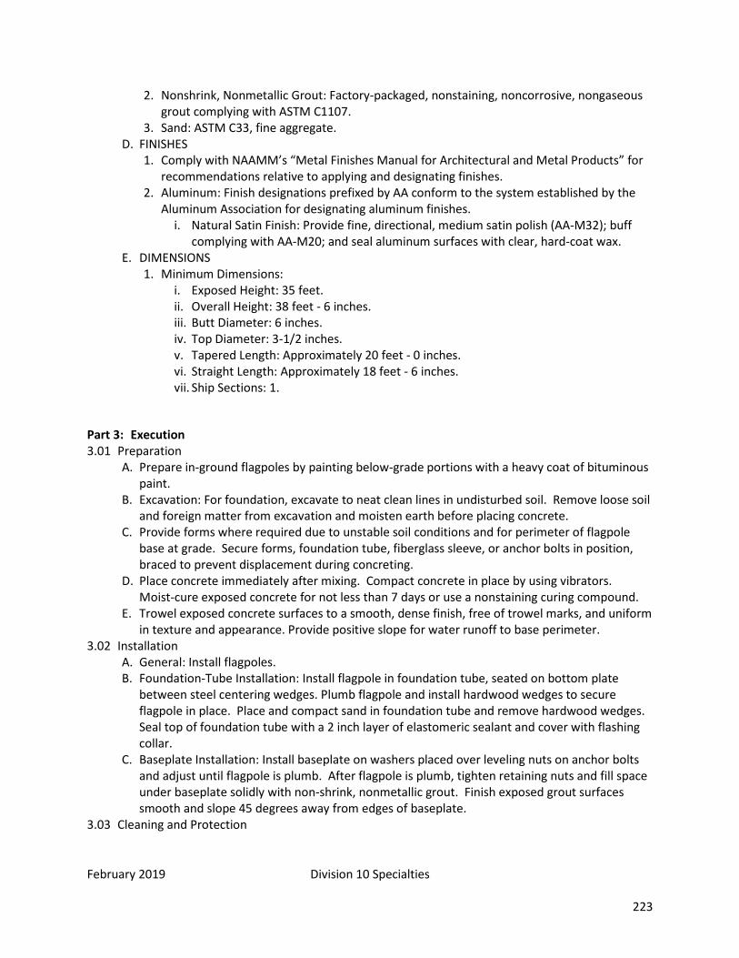
February 2019 Division 10 Specialties 223
2. Nonshrink, Nonmetallic Grout: Factory-packaged, nonstaining, noncorrosive, nongaseous grout complying with ASTM C1107.
3. Sand: ASTM C33, fine aggregate. D. FINISHES
1. Comply with NAAMM’s “Metal Finishes Manual for Architectural and Metal Products” for recommendations relative to applying and designating finishes.
2. Aluminum: Finish designations prefixed by AA conform to the system established by the Aluminum Association for designating aluminum finishes.
i. Natural Satin Finish: Provide fine, directional, medium satin polish (AA-M32); buff complying with AA-M20; and seal aluminum surfaces with clear, hard-coat wax.
E. DIMENSIONS 1. Minimum Dimensions:
i. Exposed Height: 35 feet. ii. Overall Height: 38 feet - 6 inches. iii. Butt Diameter: 6 inches. iv. Top Diameter: 3-1/2 inches. v. Tapered Length: Approximately 20 feet - 0 inches. vi. Straight Length: Approximately 18 feet - 6 inches. vii. Ship Sections: 1.
Part 3: Execution 3.01 Preparation
A. Prepare in-ground flagpoles by painting below-grade portions with a heavy coat of bituminous paint.
B. Excavation: For foundation, excavate to neat clean lines in undisturbed soil. Remove loose soil and foreign matter from excavation and moisten earth before placing concrete.
C. Provide forms where required due to unstable soil conditions and for perimeter of flagpole base at grade. Secure forms, foundation tube, fiberglass sleeve, or anchor bolts in position, braced to prevent displacement during concreting.
D. Place concrete immediately after mixing. Compact concrete in place by using vibrators. Moist-cure exposed concrete for not less than 7 days or use a nonstaining curing compound.
E. Trowel exposed concrete surfaces to a smooth, dense finish, free of trowel marks, and uniform in texture and appearance. Provide positive slope for water runoff to base perimeter.
3.02 Installation A. General: Install flagpoles. B. Foundation-Tube Installation: Install flagpole in foundation tube, seated on bottom plate
between steel centering wedges. Plumb flagpole and install hardwood wedges to secure flagpole in place. Place and compact sand in foundation tube and remove hardwood wedges. Seal top of foundation tube with a 2 inch layer of elastomeric sealant and cover with flashing collar.
C. Baseplate Installation: Install baseplate on washers placed over leveling nuts on anchor bolts and adjust until flagpole is plumb. After flagpole is plumb, tighten retaining nuts and fill space under baseplate solidly with non-shrink, nonmetallic grout. Finish exposed grout surfaces smooth and slope 45 degrees away from edges of baseplate.
3.03 Cleaning and Protection

February 2016 Division 11 Equipment 224
DIVISION 11: Equipment
SECTION 11 13 00 – LOADING DOCK EQUIPMENT
Dock Levelers: Required for loading docks over 26" high.
END OF SECTION 11 13 00
SECTION 11 31 00 – RESIDENTIAL APPLIANCES
Part 25: General 25.01 Summary
A. Section Includes: 1. Appliances:
25.02 Related Sections 25.03 Definitions 25.04 Submittals Required
A. Product Data B. Shop Drawings
25.05 Quality Assurance A. QUALIFICATIONS
25.06 Scheduling 25.07 Delivery, Storage, and Handling 25.08 Regulatory Requirements
Part 26: Products 26.01 Manufacturers 26.02 Products
A. APPLIANCES 1. Refrigerators:
i. Energy Star Rated 2. Dishwashers:

February 2016 Division 11 Equipment 225
3. Energy Star Rated Microwave Ovens: i. Energy Star Rated
Part 27: Execution 27.01 Preparation
A. Verify anchor placement is acceptable. 27.02 Installation 27.03 Cleaning and Protection
END OF SECTION 11 31 00
SECTION 11 40 00 – KITCHEN EQUIPMENT
Part 1: General 1.01 Summary 1.02 Related Sections 1.03 Definitions 1.04 Submittals Required
A. Shop Drawings B. Contractor Rough-In C. Cut Sheet Book D. Start-up Demonstration and Manuals
1.05 Quality Assurance 1.06 Scheduling 1.07 Delivery, Storage, and Handling 1.08 Regulatory Requirements
Part 2: Products 2.01 Manufacturers 2.02 Products
A. All Equipment is to be approved by the CITY OF FORT COLLINS Building Repair & Maintenance Department. This section lists typical equipment used recently as a basis for design.
B. MATERIALS 1. Stainless Steel: Stainless steel shall be of U.S. Standard gauges, but not less than 20 gauge,
Type 304 with No. 4 finish. 2. Galvanized Steel: Galvanized Steel shall be of 14 gauge and shall be hot dipped -galvanized.
Galvanized steel may be used in all non-exposed areas, areas with no contact with food or serving items and in framework. When used in framework, galvanized steel shall be of welded construction (welding is to be done before galvanizing). Use of galvanized steel will be subject to final approval during submittal check.
3. Insulation Materials: For normal temperature applications, such as custom fabricated

February 2016 Division 11 Equipment 226
under-counter refrigerators, use extruded polystyrene material 2 in. (50 mm) thick, bonded at all joints.
4. For heated-type application, such as plate warmers, use block-type rock wool, minimum 1 in. (25 mm) thick.
5. For low temperature applications, such as ice bins, cold pans, or custom fabricated under counter freezers, use urethane, rigid foam board or foamed-in-place, not less than 2 in. (50 mm) thick, except that vertical surfaces of cold pans and ice bins may be 1 in. (25 mm) thick. Bond insulation at joints to prevent condensation on exterior.
6. At counter tops subject to heat from cooking equipment and/or refrigeration compressors, use 1 in. (25 mm) thick Manville Martinite 36, or equal, to insulate underside of top. Also add Martinite material between freezer or refrigerator and 14 gauge (1.98 mm) stainless steel top.
7. Fiberglass insulation materials shall not be used. Insulation shall be bonded to all surfaces. C. METAL TOP CONSTRUCTION
1. Metal tops to be one-piece 14 gauge stainless steel welded construction including field joints. Tops to be secured to a full perimeter galvanized steel channel frames except at wood top tables, drainboards and dishtable where channel frames shall be stainless steel and cross braced not farther than 30 in. (760 mm) on center. Fasten top with stud bolts or tack welds. Coat underside of tops with a minimum 1/16 in. (1.6 mm) thick approved hard-drying, sound-deadening, mastic material. Apply all coatings by spreading after top has been secured to frame, such that top and frame are covered and sealed. Table tops must not deflect or distort when fully loaded.
D. ENCLOSED CABINET BASES 1. Fabricate bases from not less than 18 gauge (1.27 mm) steel reinforced by forming metal
ends and shelves. Partitions to be constructed of stainless steel. The ends and vertical partitions can be of single wall construction, with a 2 in. (50 mm) face partitions and sides shall be welded at intersections and be flush with the bottom edge of the bottom shelf.
2. Unexposed backs and structural members may be constructed of galvanized steel. 3. Intermediate shelves to be removable. Bottom shelves shall be non-removable. 4. All cabinet doors to be hinged left or right unless otherwise specified.
E. LEGS AND CROSS RAILS 1. Legs and cross rails to be of 1 5/8 in. diameter (941 mm), 16 gauge (1.59 mm) seamless
stainless steel tubing. All crossrails to be continuously welded, ground and polished. Tack welds or other methods of connection are not acceptable. Bottoms of legs to be wedged inward and fitted with a stainless steel bullet-type foot with not less than 2 in. adjustment. Freestanding legs are to be pegged to floor with 1/4 in. (6 mm) diameter stainless steel rods.
2. Stainless steel gussets shall not be less than 3 in. (76 mm) diameter and 3/4 in. (95 mm) long. Outer shell to be 16 gauge (1.59 mm) stainless steel reinforced with 12 gauge (2.78 mm) mild steel insert welded to interior of shell. Gusset to be large enough to accommodate a 1-5/8 in. (41 mm) tube and shall have an Allen screw fastener.
3. Low counter legs shall be constructed of stainless steel exterior and shall be 5 3/4 in. (146 mm) minimum height or 7 in. (178 mm) maximum height with 3 1/2 in. (89 mm) square plate with four countersunk holes, welded to the top for fastening.
4. Adjustable feet to be constructed of stainless steel 1/2 in. (38 mm) diameter tapered at the bottom to 1 in. (25 mm) diameter, fitted with a 3/4 in. (19 mm) cold-rolled rod threaded for minimum of 1/2 in. (38 mm) for fitting into a threaded plug welded to leg. A push-in foot is

February 2016 Division 11 Equipment 227
not acceptable. Tables with utilities will have flanged feet and will be securely bolted to the floor with stainless steel fasteners as required by local code.
5. When legs are fastened to equipment, the following methods must be used: i. Sinks: Gussets shall be welded to triangular stainless steel plates, which in turn shall
be welded to the underside of sink. ii. Metal Top Table or Dishtable: Gussetts shall be welded to 14 gauge or heavier channel
reinforcing. iii. Wood Top: Gusset shall be welded to a stainless steel channel of not less than 14
gauge stainless steel (1.98 mm), secured to the top with screws through slotted holes. F. SHELVES
1. When shelves are part of the fixture, the following must take place: i. Open base type shelf shall be notched around the leg and continuously welded to the
leg. ii. Cabinet base type shelf shall be turned-up 2" on the back side with a minimum of 1/4
in. (6 mm) radius to insure a tight fit to enclosure panels. G. WALL MOUNTED SHELVING, RACKS, AND CABINETS
1. Wall backing of sufficient size and strength to support the intended fixture when fully loaded or at full capacity.
H. SINKS, STEAM TABLES AND BAIN MARIES 1. When multiple compartments are part of the design, they shall be continuous on the
exterior without applied facing strips or panels. Bottoms of each compartment to be creased to ensure complete drainage to waste opening.
2. Partitions between compartments to be double thickness, continuous and welded. 3. Where sink bowls are exposed, the exterior shall be polished to a number 4 finish. 4. Furnish following drains, wastes and faucets manufactured by Chicago Faucets with lever
type handles, shipped loose for installation. 5. Basket strainer drains shall be Fisher Model 6555 with 3 1/2 in. (89 mm) basket. 6. Rotary drains shall be Fisher Model 6100 rotary type waste with connected overflow. Valve
to be 2 in. (50 mm) chrome plated. 7. Water stand bain maries shall be fitted with 2 1/2 in. (50 mm) waste with basket strainer
with connected overflow and adapter to connect to 1/2 in. (38 mm) drain line. Use Standard Keil box pattern basket, drain number 4161-Cp with 458-X overflow head.
8. Furnish faucets for all sinks, bain maries, water stations and other fixtures per 'D' above. If not otherwise specified, all faucets will be backsplash mounted.
9. Provide vacuum breakers on equipment. 10. Floor sinks are to be made of cast iron with porcelain enamel coating to withstand 250
deg. Temperatures, and have secure grates to prevent falls. Floor sinks are to be level with the floor to prevent a trip hazard and to allow water to flow into them. They should be positioned out of the walkway portions of the kitchen; i.e.: under the steam table serving counter or dish machine. These must be under open counter areas or positioned so that they are accessible for cleaning. A trench drain or large square drain (24in.x24in) should be used in front of the steam kettle. A stainless steel anti-splash box should be provided for draining kettles.
I. CUSTOM FABRICATED WORKMANSHIP 1. Items of specialty custom fabricated equipment must be custom fabricated by an acceptable
manufacturer, who is N.S.F. approved and custom fabricated in an approved manner.

February 2016 Division 11 Equipment 228
2. Welding and Soldering: Materials 18 gauge (1.27 mm) or heavier, shall be welded. 3. Seams and joints shall be shop-welded or soldered as the nature of the material will require. 4. Welds shall be ground smooth and polished to match original finish. 5. Where galvanizing has been burned off, the weld shall be cleaned and touched up with high-
grade aluminum paint. 6. Fasteners and Joints: The following will not be accepted:
i. Exposed screw or bolt heads. Rivets. Butt joints made by rivetting straps under seams and then filled with solder. All fasteners exposed to moisture will be stainless steel.
ii. Rolled Edges: Rolled edges with corners bullnosed, ground and polished. 7. Coved Corners: All stainless steel food service equipment shall have 1/2 in. (13 mm) or larger
radius coves in all horizontal and vertical corners and intersections per N.S.F. standards. 8. Closures: Where ends of fixtures, backsplashes, shelves, etc. are open, fill by forming the
metal, or weld sections, if necessary, to close entire opening flush to walls or adjoining fixtures.
9. Fabricated equipment having a specified manufacturer, if fabricated by another manufacturer; It shall be specifically understood that all standard accessories, construction details, and features, whether stated or not, will be met, and/or, provided by the current manufacturer.
10. All shelf, counter, or other penetrations will have properly sized grommets installed and secured to prevent accidental removal.
J. OPERATION REQUIREMENTS 1. Insure quiet operation of food service and related equipment. Provide sound deadening on
all tables, counters, undershelves, sinks and drainboards. 2. Insure bumper gaskets, stops, and any other protection is installed on all custom fabricated
equipment as needed. K. CONNECTION TERMINALS
1. All custom fabricated equipment shall be provided with standard connection terminals to make final connections on job site.
L. EXHAUST HOODS, WALK-IN COOLERS AND DISHMACHINES 1. Provide all stainless steel duct connections and collars. 2. 22 Gauge Stainless Steel Wall Flashing is required from the lowest point of the Exhaust Hood
to the top of the cove base, and full width of the hood. All seams and edges will be fully finished. Overlap seams or raw edges are not acceptable.
3. Fire dampers may be required per project. 4. Dish-machines - These are to be hot water sanitizing, with Hatco gas fired booster heater
for energy efficiency. Gas boosters are to be vented into draft hood above dishwasher using stainless steel vent pipe. A water connection (3/4 x 1/2TEE) is to be installed on the rinse piping to dishwasher (above dish-counter) with a ½ x ¼” compression stop for soap/rinse control connection.
M. INSERT PANS 1. All cut-outs, openings, drawers, and equipment to hold stainless steel insert pans shall be
provided with a full complement of pans as follows: 2. One (1) stainless steel, 20 gauge (.95 mm) minimum, solid insert pan for each space, sized
per plans, details, and specifications. 3. Provide one full-size pan to securely fit each opening. 4. Provide a maximum depth pan to suit each application and space allocated for same.

February 2016 Division 11 Equipment 229
5. Provide 18 gauge (1.27 mm) removable stainless steel adapter bars where applicable. N. TRAY SLIDES
1. Configuration of all corners, turns, and shape of tray slides for proper support and safe guidance of trays.
2. Size and shape of tray to be used in operation. O. ENCLOSURES
1. Provide and install enclosure panels secured or removable as specified for any item which houses equipment with movable parts, i.e. compressors, pumps, etc. Also, cover and provide protection for any exposed steam line or condensate line, which may be within reach of operating personnel.
P. DISPENSER (SELF-LEVELING) 1. Verify make of ware, their dimensions, and weight and submit to the dispenser
manufacturer at earliest possible date so that springs may be properly calibrated. Q. WATER FILTER-PURIFIER
1. Furnish in-line water filter-purifiers to remove contaminants, minerals, taste, or odors from beverage system, coffee urns, and icemakers, and steamers, manufactured by Everpure or equal. Provide proper size filter - purifier for equipment being supplied. Locate to insure easy access for cartridge replacement.
R. CONVENIENCE AND POWER OUTLETS 1. Make cut-outs and install appropriate boxes or outlets in custom fabricated fixtures
complete with wiring conduit, outlet and cover plate. 2. All outlets and plugs shall conform to NEMA standards. Convenience (and all 120V outlets)
will be NEMA 520R, horizontally mounted. 3. All electrical outlets and devices shall be first quality "Specification Grade."
S. PLUGS AND CORDS 1. Where cords and plugs are used, they must comply with National Electrical Manufacturer's
Association (NEMA.) requirements. T. HEATING EQUIPMENT
1. Electric and heating equipment to be installed so as shall be readily cleanable or easily removable for cleaning.
2. Steam-heated custom fabricated equipment shall be of self-contained assembly complete with control valves located in an accessible position.
3. Convection Steamers are to be “Cleveland” brand. 4. Steam Kettles are to be “Cleveland” brand. (Self-contained, natural gas). A pre-rinse faucet
combined with a fill faucet should be installed with the kettle, and have a backflow device. 5. Hot holding cabinets/proofers should be “CresCor” brand. 6. Stovetops/Ranges should be Garland brand. These need to electronic/spark ignition. (No
open pilots) 7. Convection ovens should be Blodgett: Model: DFG-100 with solid-state manual controls (not
digital), casters, flexible gas hose with quick disconnect and restraining tether. Gas manifold to be installed with individual gas cocks for each oven (top and bottom).
U. STARTERS, SWITCHES AND CONTROLS 1. Furnish all starters, motor controls, remote controls and transformers as required. 2. Locate all switches out of heat zone. 3. All starters, switches and controls shall have white on black phenolic plastic identification
plates with stainless steel screws conspicuously located on adjacent surfaces.
February 2016 Division 11 Equipment 230
V. REFRIGERATION 1. Walk-In Coolers/Freezers are to utilize BOHN (brand) condensing units and Copeland
components. Compressor Racks are to be on the roof in appropriate outdoor cabinets. All walk-ins should have a digital temperature display/alarm; it should be wired and connected to an alarm notification system to call maintenance in the event of high temperature conditions. Door latches should accommodate owner’s padlock. Walk-in thresholds are to be a smooth or ramped surface to accommodate carts rolling in/out. Condensate drains are to be insulated and encased with plastic (washable surface). Drain shall not impede in walkway outside walk-ins.
2. Refrigeration systems shall include start-up and thirteen-month parts and labor guarantee as stated herein before plus an additional four-year guarantee on all condensing units and compressors. This includes refrigerators, ice cream cabinets, icemakers, freezers, dispensers, and all other refrigerated items. Service maintenance contracts are at the discretion of the Owner.
3. All refrigeration condensing units shall include pre-wiring, pre-piping, crankcase regulator, head pressure regulator, factory-installed suction line accumulator, phased loss protection, five year warranty, main fuse disconnect, structural steel frame and weather-proof carbon steel body panel with epoxy paint finish, and refrigerant detective alarm.
4. Compressors and related components must be fully accessible for service and maintenance. 5. Reach in Refrigerators: “True” is the recommended brand.
W. COLD PANS 1. Ice pans, refrigerated pans and cabinets to be provided with breaker strips where adjoining
top or cabinet face materials, to prevent transfer of cold. X. VENTILATION OF REFRIGERATED EQUIPMENT
1. Adequate air supply and exhaust shall be provided for all self-contained or remote refrigeration condensing units, both custom fabricated and standard, as required for proper operation.
2. If additional ventilation is required to ensure correct operating temperatures, so state in a letter for evaluation and decision before purchase/fabrication.
Y. COMPONENTS 1. Coils: Coils for standard and custom fabricated refrigerators to have vinyl plastic coatings,
stainless steel housings and shall be installed in such a manner as to be replaceable. 2. Expansion Valves: Standard reach-in refrigerators and freezers, for remote refrigeration
systems, shall be complete with thermostatic expansion valves at the evaporator. 3. Thermometers: Refrigerated compartments, custom fabricated and standard shall be fitted
with flush digital type thermometers with chrome-plated bezels. Thermometers to be adjustable and shall be calibrated after installation. Thermometers shall have an accuracy of + 2oF. (1oC). Walk-in boxes will have digital alarms as noted in itemized specifications.
4. Hardware: Refrigerator hardware for standard and custom fabricated refrigerator compartments shall be solid, heavy-duty components. Hinges must be self-closing. Latches shall be magnetic edge mount-type.
5. Locks: Doors and drawers for reach-in refrigerated compartments, both custom fabricated and standard, to be fitted with cylinder locking type latches, and provided with master keys.
Z. MISCELLANEOUS METALS 1. Provide and install 22 gauge stainless steel wall flashing from the top of floor cove base to
under the lowest point of the exhaust hood(s). Flashing will extend the full width of the
February 2016 Division 11 Equipment 231
exhaust hood. 22ga stainless steel wall flashing will be installed from the top of the backsplash to the base of wall shelves at all sinks and work tables with sinks unless otherwise stated. Corner Guards (14ga Stainless Steel, 48’ high, 4” x 4”, broke at 90°, with a 5° return brake) will be installed at all outside corners of the foodservice areas. 90° brake angle will be adjusted to match the actual angle of the walls. Base of the corner guards will be at the top of the floor cove base. Provide and install all necessary trim panels and closures, including cosmetic coverings. Equipment closures will match the individual equipment finishes.
AA. MISCELLANEOUS EQUIPMENT 1. Can openers should be Edlund model: S-11 2. Garbage Disposals are to be In-Sink-erator brand with legs to the floor and should have
splashguards installed. P-traps are to be chrome -plated cast-brass. 3. Ice Machines should be cubed ice (not crushed). Manitowoc Brand is recommended. A floor
sink is needed under edge of machine to accommodate drain lines. 4. Island sinks are to have covered/protected water lines. Floor supplied water lines are not
acceptable. Water supply to come from ceiling with stainless steel chase for piping. Accessible isolation valves for each sink are required.
5. Hand sinks should have no towel or soap dispensers incorporated in design of sink. These can be provided separately to accommodate district-wide standardization of paper towels, etc.
6. Mixers/slicers should be “Hobart” brand. 7. Kitchen should have a custodial closet with a mop sink (with a backflow device on faucet). 8. Casters must be installed on all gas appliances and have flexible gas hoses with quick
disconnect and restraining tether. (front casters shall lock) 9. Grease trap is to be a one- piece design with two cast manholes level to grade and have
cleanouts for inlet and outlet. Please check with health dept for sizing guidelines. 10. Exterior Kitchen doors shall be at least 48 inches wide to accommodate removal/installation
of equipment. 11. Isle ways in kitchen shall be wide enough for removal/ installation of equipment and should
be wide enough near ovens to allow room for cooks to safely remove pans from oven and pass by with oven doors open while carrying hot pans to a nearby counter that will accommodate hot pans.
Part 3: Execution 3.01 Preparation 3.02 Installation
A. TRIMMING AND SEALING OF EQUIPMENT 1. Any space between units to walls, ceilings, floors and adjoining non-portable units shall be
completely sealed against entrance of food particles or vermin by means of trim strips, welding, soldering, or commercial joint material suitable to the nature of the equipment.
2. Sealer, when not exposed to extreme heat, shall be single part neutral curing silicone sealant.
3. Ends of hollow sections shall be closed. B. CUTTING AND FITTING
1. Do all cutting and fitting required on the equipment during installation and hook up.

February 2016 Division 11 Equipment 232
2. No cutting, notching, drilling, or altering of any kind will be done without first obtaining permission from the Owner.
3.03 Cleaning and Protection
END OF SECTION 11 40 00
February 2016 Division 12 Furnishings 233
DIVISION 12: Furnishings
SECTION 12 05 00 – COMMON WORK RESULTS OF FURNISHINGS Part 28: General 28.01 Summary
A. All furniture specs to be approved by the facility designer in Operation Services prior to ordering.
B. Furniture must be entirely freestanding and not attach to any vertical surface C. Furniture must be part of a flexible system that can be adapted for future changes. D. Furniture should be height adjustable when appropriate in areas such as workstations
28.02 Related Sections 28.03 Definitions 28.04 Submittals Required 28.05 Quality Assurance 28.06 Scheduling 28.07 Delivery, Storage, and Handling 28.08 Regulatory Requirements
A. Observe environmental precautions based on conditions. Part 29: Products 29.01 Manufacturers 29.02 Products
A. Recycled Content: 1. Steel: Minimum 16 percent post-consumer recycled content. 2. Aluminum: Minimum 75 percent recycled content.
B. See Section 01 35 63 for sustainability requirements. Part 30: Execution 30.01 Preparation 30.02 Installation 30.03 Cleaning and Protection
END OF SECTION 12 05 00
SECTION 12 20 00 – WINDOW TREATMENTS Part 1: General 1.01 Summary
A. Section Includes: 1. Horizontal metal louver blinds 2. Room darkening bead chain operated and motor operated roller shades 3. Operating hardware.

February 2016 Division 12 Furnishings 234
1.02 Related Sections 1.03 Definitions 1.04 Submittals Required
A. Shop Drawings B. Product Data C. Samples D. Schedule E. Maintenance Data F. Engineering
1.05 Quality Assurance A. QUALIFICATIONS:
1. Installers shall be approved by the manufacturers and shall be experienced in installing and adjusting blinds and shades to provide smooth trouble free operation.
B. Warranty 1. Provide 25 year / lifetime warranty from manufacturer of system.
1.06 Scheduling 1.07 Delivery, Storage, and Handling 1.08 Regulatory Requirements Part 2: Products 2.01 Manufacturers
A. HORIZONTAL LOUVER BLINDS 1. Hunter Douglas: “Celebrity” 2. Levolor: “Riviera classic” 3. Approved Equal
B. ROLLER SHADES 1. Mecho Shade Corporation 2. Draper 3. Insulroll 4. Approved Equal
2.02 Products A. HORIZONTAL LOUVER BLINDS
1. Blinds: Horizontal slat louvers hung from full-width headrail with full-width bottom rail; manual control of raising and lowering by cord with full range locking; blade angle adjustable by control wand.
2. Metal Slats: Spring tempered pre-finished aluminum; radiused slat corners, with manufacturing burrs removed; non-perforated.
i. Width: 1 inch. ii. Thickness: 0.0085 inch. iii. Slats per Foot: 16.7. iv. Color. v. Factory applied chemical conversion coating followed by baked-on synthetic resin
enamel finish coat, minimum thickness of 1.0 to 1.5 mils. vi. Factory applied natural static attraction dispersion coating. vii. Light tight rout holes.
3. Slat Support: Woven polypropylene cord, not less than 0.045 inches nor more than 0.066 inches in diameter and integrally braided ladder rungs of not less than 4 threads. Space ladders not further than 1 foot 9 inches apart and 7 inches from ends of slats.
February 2016 Division 12 Furnishings 235
4. Headrail: Pre-finished, formed steel box, with end caps; internally fitted with hardware, pulleys, and bearings for operation; same depth as width of slats; Height: Manufacturer’s standard.
i. Thickness: 0.024 inches. ii. Color: Same as slats.
5. Bottom Rail: Pre-finished, formed steel with top side shaped to match slat curvature; with end caps to match rail.
i. Thickness: 0.024 inches. ii. Color: Same as headrail.
6. Lift Cord: Braided nylon; continuous loop; self-aligning cord equalizers. i. Free end weighted.
7. Tilt Mechanism: Die cast worm and gear type; clutch action; permanently lubricated gear mechanism in fully enclosed housing. Rod shall be corrosion resistant solid steel.
8. Tilt Wand: Extruded hollow plastic; hexagonal shape. i. Removable type. ii. Length of window opening height less 3 inches. iii. Color: Clear.
9. Headrail Attachment: Brackets. 10. Optional Dust Retarder: Fabricate with manufacturer’s standard dust retardant coating.
B. ROLLER SHADES 1. Roller Shades: Laminated shade cloth, 1300 Series (5%) for Mid-Transmittance Glass.
Provide fabric with flame spread less than 25 per ASTM E84 and meeting 2003 IBC requirements for Class I finish. Include mounting brackets, supports, anchors and accessories required for a complete, operational installation. All parts shall be by one manufacturer. Plastic components shall be Delrin (DuPont). Submit one working hand sample to assure conformance.
i. No valance. ii. Shade rollers to be stainless steel bead-chain operated, except where motorized.
2. Shade Band i. Shade Bands: Construction of shade band includes the fabric, the hem weight, hem-
pocket, shade roller tube, and the attachment of the shade band to the roller tube. Sewn hems and open hem pockets are not acceptable.
a. Hem Pockets and Hem Weights: Fabric hem pocket with RF-welded seams (including welded ends) and concealed hem weights. Hem weights shall be of appropriate size and weight for shade band. Hem weight shall be continuous inside a sealed hem pocket. Hem pocket construction and hem weights shall be similar, for all shades within one room.
b. Shade band and Shade Roller Attachment: 1. Use extruded aluminum shade roller tube of a diameter and wall thickness
required to support shade fabric without excessive deflection. Roller tubes less than 1.55 inch in diameter for manual shades, and less than 2.55 inches for motorize shades are not acceptable.
2. Provide for positive mechanical engagement with drive / brake mechanism. 3. Provide for positive mechanical attachment of shade band to roller tube;
shade band shall be made removable / replaceable with a "snap-on" snap-off" spline mounting, without having to remove shade roller from shade brackets.
February 2016 Division 12 Furnishings 236
4. Mounting spline shall not require use of adhesives, adhesive tapes, staples, and/or rivets.
5. Any method of attaching shade band to roller tube that requires the use of: adhesive, adhesive tapes, staples, and/or rivets are not acceptable.
3. Shade Fabrication i. Fabricate units to completely fill existing openings from head to sill and jamb-to-
jamb. ii. Fabricate shadecloth to hang flat without buckling or distortion. Fabricate with heat-
sealed trimmed edges to hang straight without curling or raveling. Fabricate unguided shadecloth to roll true and straight without shifting sideways more than 1/8 inch (3.18 mm) in either direction per 8 feet (2438 mm) of shade height due to warp distortion or weave design. Fabricate hem as follows:
a. Bottom hem weights sealed in hem. iii. For railroaded shadebands, provide seams in railroaded multi-width shadebands as
required to meet size requirements and in accordance with seam alignment. Seams shall be properly located. Furnish battens in place of plain seams when the width, height, or weight of the shade exceeds manufacturer's standards. In absence of such standards, assure proper use of seams or battens as required to, and assure the proper tracking of the railroaded multi-width shadebands.
iv. Provide battens for railroaded shades when width-to-height (W:H) ratios meet or exceed manufacturer's standards. In absence of manufacturer's standards, be responsible for proper use and placement of battens to assure proper tracking and roll of shadebands.
4. Components i. Access and Material Requirements:
a. Provide shade hardware allowing for the removal of shade roller tube from brackets without removing hardware from opening and without requiring end or center supports to be removed.
b. Provide shade hardware that allows for removal and re-mounting of the shade bands without having to remove the shade tube, drive or operating support brackets.
c. Use only Delrin engineered plastics by DuPont for all plastic components of shade hardware. Styrene based plastics, and /or polyester, or reinforced polyester will not be acceptable.
ii. Motorized Shade Hardware and Shade Brackets: a. Provide shade hardware constructed of minimum 1/8-inch thick plated steel, or
heavier, thicker, as required to support 150 percent of the full weight of each shade.
b. Provide shade hardware system that allows for field adjustment of motor or replacement of any operable hardware component without requiring removal of brackets, regardless of mounting position (inside, or outside mount).
c. Provide shade hardware system that allows for operation of multiple shade bands offset by a maximum of 8-45 degrees from the motor axis between shade bands (4-22.5 degrees) on each side of the radial line, by a single shade motor (multi-banded shade, subject to manufacturer’s design criteria).
C. SHADE MOTOR SYSTEMS- previously used in gymnasiums 1. Shade Motors:

February 2016 Division 12 Furnishings 237
i. Tubular, asynchronous (non-synchronous) motors, with built-in reversible capacitor operating at 110v AC (60hz), single phase, temperature Class A, thermally protected, totally enclosed, maintenance free with line voltage power supply equipped with locking disconnect plug assembly furnished with each motor.
ii. Conceal motors inside shade roller tube. iii. Maximum current draw for each shade motor of 2.3 amps. iv. Use motors rated at the same nominal speed for all shades in the same room. v. Total hanging weight of shade band shall not exceed 80 percent of the rated lifting
capacity of the shade motor and tube assembly. vi. One motor shall operate three (3) shades in this example. Can be otherwise as
needed. 2. Motor Control Systems
i. IQ/MLC: Specifications and design of shade motors and motor control system are based on the IQ/MLC motor logic control system manufactured by MechoShade Systems, Inc., or “InteliFlex SC1” by Draper (as long as 3 shades per motor can be met). Other systems may be acceptable provide that all of the following performance capabilities are provided. Motor logic control systems not in complete compliance with these performance criteria shall not be accepted as equal systems.
a. Motor Control System: 1. Provide power to each shade motor via individual 3 conductor line voltage
circuits connecting each motor to the relay based motor logic controllers (IQ/MLC).
2. Control system components shall provide appropriate (spike and brown out) over-current protection (+/- 10 percent of line voltage) for each of the four individual motor circuits and shall be rated by UL or ETL as a recognized component of this system and tested as an integrated system.
3. Motor control system shall allow each group of four shade motors in any combination to be controlled by each of four local switch ports, with up to fourteen possible "sub-group" combinations via local 3 button wall switches and all at once via a master 3 button switch. System shall allow for overlapping switch combinations from two or more local switches.
4. Multiple "sub-groups" from different IQ/MLC control components shall be capable of being combined to form "groups" operated by a single 3 button wall switch, from either the master port or in series from a local switch port.
5. Each shade motor shall be accessible (for control purposes) from up to four local switches and one master switch.
6. Control system shall allow for automatic alignment of shade hem bars in stopped position at 25 percent, 50 percent, and 75 percent of opening heights, and up to three user-defined intermediate stopping positions in addition to all up / all down, regardless of shade height, for a total of five positions. Control system shall allow shades to be stopped at any point in the opening height noting that shades may not be in alignment at these non-defined positions).
7. Control system shall have two standard operating modes: Normal mode allowing the shades to be stopped anywhere in the window’s opening height and uniform mode, allowing the shades to only be stopped at the predefined intermediate stop positions. Both modes shall allow for all up / all down positioning.

February 2016 Division 12 Furnishings 238
8. Control system components shall allow for interface with both audiovisual system components and building fire and life safety system via a dry contact terminal block.
9. Control system components shall allow for interface with external analog input control devices such as solar activated controllers, 24 hour timers, and similar items; via a dry contact terminal block.
10. Reconfiguration of switch groups shall not require rewiring of the hardwired line voltage motor power supply wiring, or the low voltage control wiring. Reconfiguration of switch groups shall be accomplished within the motor control device (IQ/MLC).
b. Wall Switches: 1. Three-button architectural flush mounted switches with metal cover plate
and no exposed fasteners. 2. Connect local wall switches to control system components via low voltage
(12V DC) 4-conductor modular cable equipped with RJ-11 type connectors. 3. Connect master wall switches to control system components via low voltage
(12V DC) 6-conductor modular cable equipped with RJ-12 type connectors. 3. Accessories
i. Roller Shade Pocket for wall mounting above the 120” x 48”(approx) windows. ii. Fascia (for Shade Electro II)
a. Fascia shall be able to be installed across three shade bands in one piece. b. Continuous removable extruded aluminum fascia that attaches to shade
mounting brackets without the use of adhesives, magnetic strips, or exposed fasteners.
c. Fascia shall fully conceal brackets, shade roller and fabric on the tube. d. Provide bracket / fascia end caps where mounting conditions expose outside of
roller shade brackets. D. FABRICATION
1. Fabricate blinds to fit within openings with uniform edge clearance of 3/8 inch. 2. Fabricate room darkening shades to completely cover window frames.
Part 3: Execution 3.01 Preparation 3.02 Installation
A. Install blinds level, plumb and located so exterior louver edges in any position are not closer than 1 inch to interior face of glass lites. 1. Mount inside of window frame, not on face of frame.
B. Secure in place with concealed fasteners. C. Window treatments (roller and other types of blinds) should be fastened beyond wood trim,
reaching the window frame, blocking, or wall stud. 3.03 Cleaning and Protection
END OF SECTION 12 20 00
February 2016 Division 12 Furnishings 239
SECTION 12 30 00 – CASEWORK
Part 1: General 1.01 Summary 1.02 Related Sections 1.03 Definitions 1.04 Submittals Required 1.05 Quality Assurance 1.06 Scheduling 1.07 Delivery, Storage, and Handling 1.08 Regulatory Requirements Part 2: Products 2.01 Manufacturers
A. CASEWORK 1. TMI Systems Design Corp. 2. LSI Corp. 3. Westmark. 4. Colorado Custom Cabinets. 5. Sidney Millwork. 6. Stevens Cabinet Company. 7. Kamtz Companies, Inc. 8. Approved Equal.
B. PLASTIC LAMINATE 1. Wilsonart. 2. Approved Equal.
2.02 Products A. Preference is given for casework constructed using recycled glass concrete, synthetic cast slabs
containing fly ash, polypropylene fibers, waste marble chips, or recycled plastic where feasible. Provide documentation on the source of materials.
B. HARDWARE 1. Institutional type, five knuckle; provide one pair for doors less than 4 feet high and three
hinges per door for doors over 4 feet. 2. Pulls: Semi-flush ABS plastic pulls for drawers and swing doors, mounted with 2 screws
fastened from back. For sliding doors, provide recessed flush pulls. 3. Magnetic Catch 4. Drawer Guides: Regular drawers shall be equipped with one pair of ball-bearing nylon-
roller suspensions which shall be self-closing from 4-inch extension, have a load capacity minimum of 75 lb., and be on zinc-coated cold rolled steel. Knee drawers shall be equipped with full extension suspensions with a load capacity minimum of at least 50 lbs. Paper storage and file drawers shall be equipped with one pair of full extension suspensions of similar design with load capacity minimum of 100 lbs.
5. Adjustable Self Supports: Heavy-duty self-locking plastic with 1/4-inch diameter pin, minimum 4 per shelf. Pre drill holes in cabinet ends and partitions.
6. Locks: Provide one lock and one inside latch at wall cabinet and one drawer in each classroom. Use a cabinet lock capable of taking a SCHLAGE 6 pin interchangeable core cylinder.
February 2016 Division 12 Furnishings 240
C. Accessories: Provide casework complete with all accessories and hardware. Part 3: Execution 3.01 Preparation
A. Verify grounds, blocking, and supports for proper location and support of casework. 3.02 Installation
A. Seal top and bottom edges of all backsplashes with appropriate caulking to preclude moisture penetration.
3.03 Cleaning and Protection
SECTION 12 50 00 – FURNITURE 1.01 Summary
A. Furniture will match building standard if one exists. B. Furniture shall be part of lines and manufactures where parts will be available for at least the
next 15 years C. Furniture will have a flexible configuration in order to be adaptable in the future. D. Overhead bins may not attach to a fixed wall surface. They must attach to the base of the
desk. E. If practical based on usage, sit / stand options should be incorporated. F. All questions regarding furniture shall be directed to the Facility Designer in Operation
Services.
END OF SECTION 12
DIVISION 13: Special Construction
SECTION 13 27 00 – VAULTS
Part 31: General 31.01 Summary
A. Utility Vaults and terminations are required to serve future sites. B. All in-ground vaults to be traffic rated. C. Section Includes:
1. Power Vault 2. Low Voltage Vault 3. Gas/Water Termination Pad

February 2016 Division 13 Special Construction 241
4. Sewer Termination Pad 31.02 Related Sections 31.03 Definitions 31.04 Submittals Required 31.05 Quality Assurance 31.06 Scheduling 31.07 Delivery, Storage, and Handling 31.08 Regulatory Requirements
Part 32: Products 32.01 Manufacturers 32.02 Products
Part 33: Execution 33.01 Preparation 33.02 Installation
A. Power Vault: 1. Location:
i. At building ii. Within 5 feet of Low Voltage Vault. iii. 15 to 20 feet away from Gas/Sewer/Water pads. iv. Label vaults on the backside of vault cover with the panel label ID and electrical room
number from where it is fed. v. Label all underground conduits where they are fed from and/ or where they feed to
on each end. 2. Size: 3' x 2' x 2' deep open bottom fiberglass vault. Traffic rated. 3. Connections:
i. Two 2-inch 480 V conduits to Main Distribution Center; and/or ii. Two 2-inch 120/208V conduits with pull string.
4. Connection depth: 24 inches below grade. B. Low Voltage Vault:
1. Location: i. At designated temporary classroom area. ii. Within 5 feet of Power Vault. iii. 15 to 20 feet away from Gas/Sewer/Water pads. iv. Label vaults on the backside of vault cover with the panel label ID and electrical room
number from where it is fed. v. Label all underground conduits where they are fed from and/ or where they feed to
on each end. 2. Size: 3' x 2' x 2' deep open bottom fiberglass vault. Traffic rated. 3. Connections for Fire Alarm, Intercom, Security, Data, CATV, Telephone:
i. Two 3-inch conduits to communication room. ii. One 1-inch conduit to Fire Alarm Control Panel.
4. Connection depth: 24 inches. C. Gas/Water Termination Pad:
1. Location:

February 2016 Division 13 Special Construction 242
i. At designated temporary classroom area. ii. Adjacent to Sewer termination pad. iii. 15 to 20 feet away from Power Vault and Low Voltage Vault.
2. Size: 2-inch square x 4 inch thick concrete pad with cast-in lettering designating each utility.
3. Connections: i. Gas: 2-inch polyethylene line with built-in tracer line with shutoff valve and cap at
gas meter. ii. Water: 1-inch minimum type K copper line with shutoff valves inside main building
and curb stop termination. 4. Connection depth: 24 inches minimum. 5. Other: Yellow safety marker tape above both lines.
D. Sewer Termination Pad: 1. Location:
i. At designated temporary classroom area. ii. Adjacent to Gas/Water termination pad. iii. 15 to 20 feet away from Power Vault and Low Voltage Vault.
2. Size: 24-inch square x 4-inch thick concrete pad. 3. Connections:
i. Sewer: Extend and plug 4 inch line 5'-0" beyond cleanout wye. Terminate cleanout with coverplate at concrete pad.
4. Connection depth: 36-inch minimum. 5. Other:
i. Yellow safety marker tape above sewer line. ii. Cast iron sewer pipe required under vehicle areas. iii. Cleanout required at 100-foot intervals.
33.03 Cleaning and Protection
END OF SECTION 13 27 00
February 2016 Division 14 Conveying Equipment 243
DIVISION 14: Conveying Equipment
SECTION 14 20 00 – ELEVATORS Part 1: General 1.01 Summary
A. Pre-engineered traction passenger elevator system not requiring a machine room with a small closet adjacent the elevator shaft, pit ladder, controllers, equipment, and fittings.
B. All elevators shall have a battery backup system that returns the elevator to the lowest floor and opens the doors in the event of a power outage.
1.02 Related Sections 1.03 Definitions 1.04 Submittals Required
A. Shop Drawings B. Product Data C. Samples D. List of Successful In-Service Projects E. Closeout Submittals
1.05 Quality Assurance A. WARRANTY
1. Special Project Warranty: Provide special project warranty, signed by Contractor, Installer and Manufacturer agreeing to replace, repair or restore defective materials and workmanship of elevator work during warranty period. This warranty shall be in addition to, and not a limitation of, other rights the Owner may have against the Contractor under the Contract Documents.
2. Warranty period is 2 years starting on the date of Substantial Completion. Service shall be performed once every 90 days minimum.
B. MAINTENANCE SERVICE 1. Furnish service and maintenance of elevator for one year from Date of Substantial
Completion. State services, obligations, conditions and terms for agreement period and for future renewal options.
1.06 Scheduling 1.07 Delivery, Storage, and Handling 1.08 Regulatory Requirements
A. Electric Traction Passenger Elevators 1. Controls System:
i. Single Automatic Operation elevator control system, two-way self-leveling. 2. Interconnect elevator control system with building fire alarm.
Part 2: Products 2.01 Manufacturers
A. Kone (preferred)

February 2016 Division 14 Conveying Equipment 244
B. Thyssen Krupp Elevator Systems, Inc. C. Approved Equal.
2.02 Products A. METAL
1. Recycled Content: Minimum 5 percent post-consumer recycled content, or minimum 20 percent pre-consumer recycled content at contractor’s option.
B. HYDRAULIC FLUID 1. Biobased Content: Hydraulic Fluids – Stationary Equipment: Fluids formulated for use in
stationary hydraulic equipment systems that have various mechanical parts, such as cylinders, pumps, valves, pistons, and gears, that are used for the transmission of power (and also for lubrication and/or wear, rust, and oxidation protection). Provide minimum 44% bio-based content.
2. Resource Management: Assess biodegradability of hydraulic fluids in accordance with ASTM D6006.
i. Environmental persistence of hydraulic fluids: Pw1 in accordance with ASTM D6046. Class Pw4 will not be permitted.
ii. Acute ecotoxicity: Ts1 for soil and Tw1 for water in accordance with ASTM D6046. C. ELECTRICAL CHARACTERISTICS AND COMPONENTS
1. Disconnect Switch to be located next to control panel. 2. Products Requiring Electrical Connection: Listed and classified by Underwriters'
Laboratories, Inc., as suitable for purpose specified and indicated. 3. Phone in car: auto dial to the City Number to be determined per job, when handset is
picked up. D. EQUIPMENT: CONTROL COMPONENTS AND CONTROL SPACE (Electric Traction Passenger
Elevators ONLY) 1. Controller: Provide microcomputer based control system to perform all of the functions.
i. All high voltage (110V or above) contact points inside the controller cabinet shall be protected from accidental contact in a situation where the controller doors are open.
ii. Controller shall be separated into two distinct halves; Motor Drive side and Control side. High voltage motor power conductors shall be routed and physically segregated from the rest of the controller.
iii. Provide a serial card rack and main CPU board containing a non-erasable EPROM and operating system firmware.
iv. Variable field parameters and adjustments shall be contained in a non-volatile memory module.
2. Drive: Provide Variable Voltage Variable Frequency AC drive system to develop high starting torque with low starting current.
E. FABRICATION 1. Car:
i. Flooring: Resilient sheet flooring ii. Walls: Plastic laminate on plywood. iii. Front Return Panel: Stainless steel. iv. Base: Resilient rubber cove v. Ceiling: Translucent plastic panel. vi. Light Fixtures: LED Minimum of 5 foot candles at controls, platform, threshold and
landing sill. vii. Ventilation: Fan, grille in ceiling.
February 2016 Division 14 Conveying Equipment 245
viii. Car Control Panel and Face Plate: Stainless steel with illuminating call buttons. Flush mount faceplates complying with ASME/ADA. If not otherwise indicated, mount in return panel adjacent to car door. Provide operating device symbols as required by Code and with braille. Mark other buttons and switches with manufacturer’s standard tactile identification and braille for required use or function. Main entry floor shall also be designated by a ”star.” Tactile markings shall be placed immediately to the left of the button to which they apply. Characters and symbols shall contrast with their background. Provide key switch for roof access.
ix. Car Position Indicator: Above door with illuminating “up” and “down” signal arrows or digital numeric display. Also provide an audible signal to indicate that a car is arriving in response to a hall call and to indicate direction of car travel. Signal shall sound once for up direction of travel and twice for down direction. 2-1/2 inches minimum in the smallest dimension.
x. Hand Rail: Stainless steel flat bar stock, spaced from wall 1-1/2 inches; placed at rear wall and side walls.
xi. Bumper Rail: Stainless steel wrapped over wood, tight to wall; placed 6 inches above floor at rear wall and side walls.
xii. Pad Hooks: Stainless steel type. xiii. Protective Pads: One set, canvas cover, padded, brass grommets. xiv. Certificate Frame and Glazing: Stainless steel frame, clear plastic. xv. Telephone: Provide rough-in for telephone hand set in each car, contained in flush-
mounted cabinet and complete with identification and instructions for use. The mounting height shall be a maximum of 4 feet and shall be identified by a raised symbol adjacent to the device. Telephone shall automatically dial the City Number to be determined per job upon lifting. Stencil (paint) the name of the building and the project street address on the back side of the telephone access door.
xvi. Alarm System: Provide emergency alarm bell properly located within building and audible outside hoistway, equipped to sound automatically in response to emergency stops and in response to “Alarm” button on each car control station.
xvii. Provide “NO SMOKING” text on car control panel to match other text on panel. Provide “In Case of Fire Use Stairway” signs with appropriate graphic symbols and braille to match other text on panel.
2. Car Entrances: i. Car Doors: Baked enamel on steel; of insulated sandwich panel construction, flush
design, rolled profiles, rigid construction. Provide protective edge trim system. ii. Car Door Frames: Baked enamel on steel, welded corner design with smooth
invisible joints. iii. Thresholds: Extruded aluminum type.
3. Hoistway Entrances: i. Hoistway Doors: Baked enamel on steel; of insulated sandwich panel construction,
flush design, rolled profiles, rigid construction. ii. Hoistway Door Frames: Baked enamel on steel; of rolled profiles, welded corner
with smooth invisible joints. iii. Door and Frame Construction: 1-1/2 hour fire rating. iv. Weatherstrip hoistway doors and frames to eliminate audible noise. v. Sills: Extruded aluminum. vi. Jambs: Floor designation characters to be a minimum of 2 inches high, raised 1/32
inch, uppercase and corresponding Braille. Locate per ADA requirements.

February 2016 Division 14 Conveying Equipment 246
F. SIGNAL EQUIPMENT 1. General: Provide signal equipment for each elevator to comply with requirements
indicated below: 2. Provide illuminated hall car-call/landing buttons that lights when activated and remains
lighted until call or other function has been fulfilled. Provide one for originating UP and one for originating DOWN calls, one button only at terminating landings. Fabricate of vandal-resistant translucent plastic. Call buttons to be 3/4 inch minimum in the smallest dimension; vertical button arrangement; flush or raised. Locate per ADA requirements.
3. No Fire Department “Recall”. 4. Car Direction Indicators: Illuminating white, minimum of 2-1/2 inches in smallest
dimension. In conjunction with the car riding lantern device, provide an audible signal to indicate that a car is arriving in response to a hall call and to indicate direction of car travel. Signal shall sound once for up direction of travel and twice for down direction. Lantern must be visible from proximity of Hall Call button. Locate per ADA requirements.
5. Door and Signal Timing for Hall Calls: Minimum of 5 seconds between notification until doors begin to close.
6. Door Closing Time Delay: Minimum of 3 seconds for doors to remain fully open in response to a call.
G. FACTORY FINISHING (Electric Traction Passenger Elevators ONLY) 1. Baked Enamel on Steel: Clean and degrease metal surface; apply one coat of primer
sprayed and baked; two coats of enamel sprayed and baked; color as selected. 2. Stainless Steel: #4 Satin Polished. 3. Aluminum: Clear anodized finish.
H. PERSONAL PROTECTIVE DEVICES 1. Door Edge Protective Device: Provide retractable edge shoe on leading edges of elevator
entrance doors that causes doors to stop and reopen upon contacting an obstruction in entrance.
2. Photo-Eye Detection Device: Provide electronic photo-eye device with timed cutout, projecting dual light beams across car entrance at 5 inch and 2 feet 5 inch heights, that when interrupted will cause closing doors to stop and reopen. Provide keyed switch in car operating panel or toggle switch in service carinet for disconnecting photo-eye protective device.
3. Nudging Feature: After car doors are prevented from closing for a predetermined adjustable time period, through activation of detection device or door edge protective device, a loud buzzer shall sound and doors shall begin to close at reduced rate of speed. Doors shall continue to close unless door edge protective device is activated, which shall cause doors to reopen. Process shall repeat continuously until obstruction is removed from entrance.
I. ELEVATOR PIT LADDER 1. Fabrication: Provide an elevator pit ladder made of structural grade steel. 2. Code Requirements: Ladder shall meet applicable code requirements.
J. WORK BY THE GENERAL CONTRACTOR 1. To be determined on project basis
K. FAILURE PROTECTION 1. General Requirements: Design electrical control circuit so that if a malfunction should
occur due to motor failure, oil becoming low in system (Hydraulic system ONLY), power failure, or car failing to reach a landing in the “up” direction within a pre-determined time, the elevator car will automatically descend to lowest terminal landing (battery backup

February 2016 Division 14 Conveying Equipment 247
required. If power operated doors are used, doors will automatically open when car reaches that landing to allow passengers to depart. Doors will then automatically close and control buttons, except the “door open” button in car station, shall be made inoperative.
Part 3: Execution 3.01 Preparation 3.02 Installation
A. Install in accordance per manufacture recommendations. B. Demonstration: Instruct Owner’s personnel in proper use, operations and daily maintenance
of elevators and lift. Review emergency provisions, including emergency access and procedures to be followed at time of failure in operation and other building emergencies. Train Owner’s personnel in normal procedures to be followed in checking for sources of operational failures or malfunctions. Confer with Owner on requirements for a complete elevator and lift maintenance program. Make a final check of each elevator with Owner’s personnel present and just prior to date of Substantial Completion. Determine that control systems and operating devices are functioning properly.
C. Provide Owner with remote diagnostic tool required to program the elevator. 3.03 Cleaning and Protection
Part 4: END OF SECTION 14 20 00
February 2016 Division 21 Fire Suppression 248
DIVISION 21: Fire Suppression
SECTION 21 05 00 – COMMON WORK RESULTS OF FIRE PROTECTION
Part 34: General 34.01 Summary 34.02 Related Sections 34.03 Definitions 34.04 Submittals Required 34.05 Quality Assurance 34.06 Scheduling 34.07 Delivery, Storage, and Handling 34.08 Regulatory Requirements Part 35: Products 35.01 Manufacturers 35.02 Products: See Plumbing Sections
Part 36: Execution 36.01 Preparation 36.02 Installation
A. EXCAVATING, TRENCHING, AND BACKFILLING B. PIPING INSTALLATION
1. General: i. Arrange pipe in group runs where feasible. Coordinate locations with all trades.
Avoid traps in piping. C. ELECTRICAL: See Electrical Sections
36.03 Cleaning and Protection
END OF SECTION 21 05 00
SECTION 21 11 00 – FACILITY FIRE-SUPPRESSION WATER-SERVICE PIPING
Part 1: General 1.01 Summary
A. Work involved with remodeling existing systems shall be done in accordance with NFPA-13. Provide new sprinkler heads in all locations where existing head layout is altered. Verify existing piping arrangement, conditions, and locations at site before beginning fabrication.
1.02 Related Sections 1.03 Definitions

February 2016 Division 21 Fire Suppression 249
1.04 Submittals Required 1.05 Quality Assurance 1.06 Scheduling
A. All drawings and sprinkler calculations are subject to Insurance Services Offices and/or Poudre Fire Authority review and approval as well as the Architect/Engineer's before installation.
1.07 Delivery, Storage, and Handling 1.08 Regulatory Requirements Part 2: Products 2.01 Manufacturers 2.02 Products
A. SIAMESE FIRE DEPARTMENT CONNECTIONS 1. Siamese connections shall be Croker Fire Equipment No. 6010, or equal, with clapper valve,
FM approval, brass finish. Threads shall be identical to those used in the city in which system is being installed and shall meet requirements of local fire department. 2-1/2" x 2-1/2" x 4" with cast brass plugs and chains. Siamese connection for sprinkler system shall have a 4" underwriter's swing check valve with ball drip; extend drain from ball drip to a predetermined City location. Brand "Auto Sprinkler."
B. FLOW ALARMS AND SUPERVISORY VALVE SWITCH 1. Flow alarms shall be Autocall Type WF, Potter Model VSR, Grinnell E-1, or approved equal,
DPST flow alarms with suitable adjustable retards. Flow alarms shall be suitable for 120-volt operation. Factory Mutual (FM) approved and UL listed.
2. Provide a UL-approved switch for main sprinkler valve(s) where indicated. Switch shall give alarm indication when main valve is closed. Switch shall be suitable for 120-volt operation.
C. SPRINKLER SYSTEM 1. Automatic sprinkler system shall be designed by the Contractor for hazard indicated. Entire
system shall be in accordance with NFPA and as specified herein and/or indicated. Contractor is herein given the option of sizing sprinkler system per pipe sizing tables in NFPA-13 or by the hydraulic method.
i. Contractor is responsible for obtaining all necessary flow tests at site required for hydraulic calculations.
ii. System shall be dry or glycol filled and sized to avoid possible freezing. 2. Hydraulic design methods shall conform to the methods outlined in NFPA No. 13 and shall
provide for pipe sizes such that not more than a 10% variation will occur in sprinkler discharge. Hazen and Williams formula with C=120 shall be used in hydraulic calculations, and additional requirements specified herein. Design conditions shall be based on the most remote 1,500 square feet for each zone. Design shall be light hazard with a design density of 0.10 GPM per square foot, or as determined by the authority having jurisdiction.
3. Prior to starting fabrication or installation of sprinkler system, Contractor shall submit detailed 1/8-inch scale (minimum) shop drawings, stamped "Reviewed" by agency having jurisdiction, to Architect/Engineer for review and approval. At time of completion of work, obtain certificate of inspection and approval from same agency.
4. Approved Manufacturers: i. Viking Sprinkler Corporation. ii. Grinnell Company, Inc. iii. The Automatic Sprinkler Corporation of America. iv. Grimes Company.
February 2016 Division 21 Fire Suppression 250
v. Approved equal selected from "List of Inspected Fire Protection Equipment and Materials" published annually by Factory Mutual Engineering and UL and shall bear UL-approved stamp or label.
5. In rooms and/or spaces where sprinkler head locations are not indicated, locate sprinkler heads to avoid conflicts with other pieces of equipment such as lights, speakers, diffusers, etc., located in ceiling. Consult Architectural, Mechanical, or Electrical plans carefully to avoid conflicts.
6. System shall be provided complete with water supply connection, sprinklers, all piping, fittings, valves, seals, test connections, hangers, supports, sleeves, escutcheons, drain valves, test connections, signs, diagrams, etc., all as required for a complete and operating system. All drain and test valves must be ball valves. Provide drain valves at all low points.
7. Fire Sprinklers: i. All sprinklers shall be automatic closed spray type sprinkler heads of ordinary degree
temperature rating except where excess temperatures are anticipated; heads shall be of higher rating.
ii. Sprinkler heads installed in areas which do not have suspended ceilings shall be of brass upright type. Sprinklers shall be installed with consideration being given to all ductwork, piping, etc., and heads shall be located above and/or below ductwork as required by NFPA Standards.
iii. Sprinkler head protections to be installed when damage could occur. iv. Sprinkler heads installed in areas which have suspended ceilings shall be of the
concealed sprinkler type with flat white cover plate. a. Braided stainless steel flex heads may be used b. Corrugated flex heads are not allowed
v. Side wall sprinkler heads indicated shall be sidewall chrome plated with chrome plated flat type escutcheon plate.
vi. Provide stock of spare heads, of each type installed, packed in a suitable cabinet. Number of each type of spare heads to be provided shall be as indicated in NFPA-13. The cabinet shall contain at least two sprinkler head wrenches.
vii. Upright sprinklers located as to be subject to mechanical injury shall be protected with approved guards.
D. BACKFLOW PREVENTER 1. Shall be double check type. 2. Two independent "Y" type spring-loaded ductile check valves, two OS&Y shut-off valves, and
four test clocks. 3. With stainless steel center-guided checks with soft elastomer discs for drip-tight closure
against backflow. 4. UL-listed for fire line service. 5. Backflow preventer to be full line size. 6. Febco Model 850 C. All other types of backflow preventors must be approved by City of Fort
Collins. Part 3: Execution 3.01 Preparation 3.02 Installation 3.03 Cleaning and Protection
END OF SECTION 21 11 00
February 2016 Division 22 Plumbing 251
DIVISION 22: Plumbing
SECTION 22 05 00 – COMMON WORK RESULTS FOR PLUMBING Part 37: General 37.01 Summary 37.02 Related Sections 37.03 Definitions 37.04 Submittals Required 37.05 Quality Assurance 37.06 Scheduling 37.07 Delivery, Storage, and Handling 37.08 Regulatory Requirements Part 38: Products 38.01 Manufacturers 38.02 Products
A. PIPE AND FITTINGS 1. Pipe and Fitting Schedule: 2. Standpipe and fire sprinkler piping:
i. Standpipe and fire sprinkler piping shall be black steel, Schedule 40, screwed, or grooved with mechanical joints, UL approved, 175 pound working pressure. Miscellaneous drain lines receiving cooling coil condensate, drip for humidifiers, etc.:
a. Piping shall be Type "L" copper, fittings wrought copper, solder joint; or approved equal.
ii. Compressed air piping in building above ground (shop air): a. Piping shall be type "L" hard copper with wrought copper or cast brass fittings.
iii. Refrigeration piping: a. Piping shall be ACR hard drawn copper tubing cleaned, dehydrated and sealed.
Use soft drawn dehydrated and sealed seamless copper tube where bending is required except where subject to physical damage. Fittings wrought copper solder fittings. Joints: 15% silver brazing alloy and silver brazing flux or brazed with Surebraze. Support piping as required to prevent damage to pipe. Run nitrogen through pipes 1" and larger when silver soldering.
3. Chemistry labs, Science labs, and photo labs: i. Acid resisting waste in building underground must be used for science and photo
labs: a. Piping shall be AB-5 or other acid resistant pipe such as Schedule 80
polyvinylidene fluoride (PVDF) or schedule 40 polypropylene (PP), mechanical joint, as designed and approved. Fittings with socket ends, same material as pipe. Provide flanged and/or threaded ends where required for connection to valves and equipment. Joints: Thermoseal fusion welding process in accordance with manufacturer's recommendations. Fuseal, Orion, or prior approved equal.

February 2016 Division 22 Plumbing 252
b. Install neutralizing basin as close to the source of effluent as possible. Provide sufficient length of PVDF pipe downstream of basin to effect dilution in event of failure of the neutralizing basin.
c. Place neutralizing basin in cabinet under sink. Not allowed to be underground. Provide union connections at all connections to tank.
ii. Acid resisting waste and vent in building above ground shall be the same as above except it shall be flame retardant.
4. Art Classrooms: Provide adequate solids interceptors to collect clay particles. Provide union connections on inlet and outlet of interceptors.
i. Acceptable Manufacturers: a. Zurn. b. Smith. c. Josam. d. Wade
5. Provide standard weight IPS brass nipples and adapters where required between copper tubing and fixtures. Steel, Galvanized or iron nipples are not permitted between copper lines and brass valves or trim.
6. Joints: Joints in all copper domestic piping systems shall be made using 95/5 tin/antimony or equal tensile strength solder that contains no lead. Engelhard "Silvabrite 100," Oatey "Safeflo," or Canfield "Watersafe" are all acceptable. Use flux recommended by solder manufacturer. Absolutely no lead containing solders or fluxes will be allowed in any portion of the work. The District reserves the right to inspect solders, fluxes and joints. Any joint found containing lead solder shall be cause for resoldering all joints made in all systems in the building. Copper heating and chilling piping systems shall be brazed for 2” pipes and smaller, except connections to valves and unit ventilators, etc., that may be damaged by the heat.
7. All copper tubing to be reamed to full inside diameter of the tubing. i. If copper pipe is found NOT reamed at any one location, contractor may be required
to disassemble all piping and have a consultant approved by the engineer and City of Fort Collins to verify reaming. Cost for ALL deconstruction and put back to be paid by the contractor whether all locations are non-compliant or not.
8. All welding fittings shall be Tube Turn, Taylor Forge, B&W, Ladish or Yoloy. 9. T-drill, Press Fit type fittings, Shark Bit Fittings, Copper Grooved, Grooved fittings are not
acceptable in hydronic, chilled, or domestic water systems. B. PERMISSIBLE ASSEMBLIES FOR WELDED PIPING SYSTEMS
1. Service working pressure is limited to 160 psig. 2. Weld all black steel piping 2-1/2" and larger except where flanges are required. End to
end butt weld joints 3/4" through 2" pipe are allowed only with internal welding rings. 3. Where welding rings are used, machine pipe ends for proper fit. 4. Elbows: Use welding elbows. 5. Tees: Use welding tees. Weldolets are allowed in shop prefabricated assemblies or in lines
5" and larger, providing all slag is removed from inside the piping. 6. Reducers: Use welding reducers. 7. Caps: Use welding caps. 8. Prepare pipe ends in tees, laterals, and reducers for weld penetration in accordance with
ASA standards. 9. Mitered elbows, tees, and reducers are prohibited in welded lines. 10. Elbows: Use long radius butt-welding elbows in expansion loops and bends.

February 2016 Division 22 Plumbing 253
11. Use long radius reducing butt-welding elbows at equipment where a 90-degree bend and size change is required.
12. National Certified Pipe Welding Bureau or AWS shall certify welders and procedures. Part 39: Execution 3.01 Preparation
A. EXCAVATING, TRENCHING, AND BACKFILLING 1. Excavation: Trenches for all underground pipe lines shall not be carried below the required
depths except as necessary for special pipe bedding or to remove unstable soil or rock. 2. When work is in public highway or street, paving repairs shall be equal to and comply with
municipal agency requirements. If repairs are done by municipal agency, make necessary arrangement with such agency to make the repairs.
3.02 Installation A. PIPING INSTALLATION
1. General: i. Use straight round pipe. Reamed to full size after cutting. Remove all chips from
reaming. ii. Arrange pipe in group runs where feasible. Coordinate locations with all trades.
Avoid traps in piping. iii. Install piping to take advantage of every available means to facilitate thermal
expansion of pipe. Provide anchors and guides to control direction of travel. Guides shall be Keflex type B with BH hanger, or Adsco, or type P, for insulated pipe. Provide ample length to maintain 25% engagement with maximum pipe travel. Provide anchors for domestic water piping serving automatic dishwashers.
2. Expansion loops shall be used for expansion compensation. Install anchors at both ends of pipe lengths served by expansion loops so that pipe movement due to expansion is directed toward the expansion loop without damaging the building construction. Both sides of the expansion loop shall be anchored. As a minimum, locate one guide 4 pipe diameters and the second guide 14 pipe diameters from each side of the expansion loop. Both sides of the expansion loop shall have two guides.
3.03 Cleaning and Protection A. DISINFECTING AND SPECIAL CLEANING
1. When a new system is to be connected to an existing system, isolate the new system for cleaning and flushing if applicable. Reaming chips must be removed by flushing, cleaning strainers, etc.
END OF SECTION 22 05 00
SECTION 22 05 19 – METERS AND GAUGES FOR PLUMBING PIPING Part 1: General 1.01 Summary
A. Comply with MSS-92-1980, Valve User’s Manual. 1.02 Related Sections 1.03 Definitions
February 2016 Division 22 Plumbing 254
1.04 Submittals Required 1.05 Quality Assurance 1.06 Scheduling 1.07 Delivery, Storage, and Handling 1.08 Regulatory Requirements Part 2: Products 2.01 Manufacturers 2.02 Products
A. PRESSURE GAUGES 1. Pressure Gauges: Three-inch minimum face diameter, 1/4" pipe thread bottom mount,
steel case, accuracy 1% of full scale or better. 2. Pressure gauges in pipelines shall be phosphor bronze bourdon tube with stainless steel
movement. 3. Gauges shall be compound, pressure or vacuum as required with 4-1/2 inch diameter dial.
Each gauge shall be complete with pulsation dampener, and 1/4" or 3/8" ball valve. Gauges on steam and steam condensate lines shall also have a siphon loop.
4. The gauges shall be located and mounted to be conveniently read by a person standing on the equipment room floor. Accuracy shall be 1/2 percent. Case shall be aluminum.
5. For water or air services, use a bronze bourdon tube, steam services, a stainless steel tube, and materials for corrosive services shall be custom selected by the Engineer.
6. Maximum Range: Approximately double the expected working pressure of the service. 7. Install with an isolation valve and a drain valve between the gauge and the isolation valve. 8. Install a pressure snubber or needle valve in services with rapid pressure pulses at pump
locations. 9. White face with black lettering. 10. Have the capacity to be calibrated with a screwdriver. 11. Acceptable Manufacturers:
i. Ashcroft. ii. Dwyer. iii. Foxboro. iv. Honeywell. v. Johnson. vi. Marsh. vii. Marshalltown. viii. Meriam. ix. Mueller Brass. x. U.S. Gauge. xi. Weiss. xii. Trerice. xiii. Or approved equal
12. Manometers and gauges calibrated in pressures less than 50 inches of water shall be by Dwyer or Meriam.
B. THERMOMETERS 1. Painted vertical metal case at least 8" long with a glass or Lucite face. 2. Furnish and install thermometers in pipe lines and equipment as scheduled and/or
indicated. Thermometers shall be Taylor, Moeller, Rochester, Weiss, Trerice, or approved equal. Nine inch scale with separable socket, cast aluminum case, red reading mercury,

February 2016 Division 22 Plumbing 255
adjustable industrial type complete with thermometer wells. Scale range shall be 30°F to 240°F with 2-degree divisions.
3. Thermometer installation will not be accepted unless easily read by an operator standing on the floor.
4. Bottom or back pipe thread connection. 5. Use thermal wells with heat transfer enhancement compound in piping services. 6. Range: At least 50% higher than the highest expected temperature of the service and at
least 20 degrees lower than the lowest expected temperature. 7. Accuracy: 1% of full scale or better.
C. PRESSURE AND TEMPERATURE SENSING PLUGS* 1. Provide where indicated 1/4" NPT fitting to receive either a 1/8" O.D. temperature or
pressure probe. Fittings shall be brass with valve core suitable for 275°F. Plugs shall be complete with gasketed cap and units shall be rated for 1000 psi. "Pete's Plug" by Peterson or Nordel, Model 45PT-N- 1-1/2".
2. Provide for use with Pete’s Plug, two 2" dial pocket testing thermometers, having a range of 0 to 250°F, and two 2" pressure gauges having a range of 0 to 150 psi. (Acceptable manufacturers are the same as above.)
Part 3: Execution 3.01 Preparation 3.02 Installation
A. SPECIAL DEVICES 1. Install a pressure-temperature tap on each side of each pump and heat transfer device
such as coils, heat exchangers, radiators and radiant panels. 2. Install one hydronic balancing valve as defined above in series with each air handling unit
coil, heat exchanger, each section of fin tube radiators or radiant panels. A section is defined as that assembly controlled by one stat/temperature control valve combination. Provide isolation valves on each side of control valve. Circuit setters are no to be used as isolation valves.
3. See following coil piping details. 4. Expansion tanks, air separators and other devices heavier than 200 pounds may not be
suspended from overhead without written permission from the Structural Engineer. 5. Provide a wrench operated main gas shut off valve, for Fire Department use, outside the
building and upstream of the meter. Coordinate with PSCo for location and who provides valve.
6. Flow (paddle) Switches shall be used where required to prove flow through low head pumps, usually boiler and coil circulators. The Engineer shall carefully and fully detail flow switch installation. Provide isolation valves on both sides of flow switches.
B. IDENTIFICATION 1. Label all mechanical devices in accordance with ANSI Standards. 2. Label all valves with tags indicating service and number. Tags 1-1/2" in diameter, brass,
with 1/4" high black letters. Securely fasten with chain and hook. Match service abbreviations given on mechanical drawings. Show all valve tag numbers on red line drawings at valve locations. All valves located behind access panels or located above ceiling tiles are to be labeled per section 22 05 53 2.02, D, 4.
3. Do not paint or insulate over nameplates. 4. Label mechanical equipment with 4" x 6" engraved plastic laminate signs with 1" high
letters.

February 2016 Division 22 Plumbing 256
C. TESTING 1. Test all operating devices. Keep written records of all tests, at minimum: the date of the
test, system or subsystem tested; test medium and pressure used; duration of test; test results; name and signature of individual performing test.

February 2016 Division 22 Plumbing 257
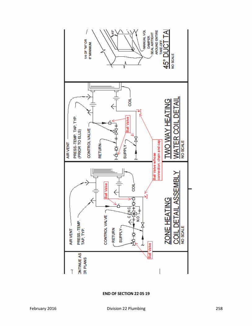
February 2016 Division 22 Plumbing 258
END OF SECTION 22 05 19
February 2016 Division 22 Plumbing 259
SECTION 22 05 23 – GENERAL-DUTY VALVES AND UNIONS FOR PLUMBING Part 1: General 1.01 Summary
A. Comply with MSS-92-1980, Valve User’s Manual. 1.02 Related Sections 1.03 Definitions 1.04 Submittals Required 1.05 Quality Assurance 1.06 Scheduling 1.07 Delivery, Storage, and Handling 1.08 Regulatory Requirements Part 2: Products 2.01 Manufacturers 2.02 Products
A. Valves 1. Provide shut-off valves in lines serving each piece of equipment such as wall hydrants and
sill cocks. Provide ball valve isolation on each side of equipment such as mixing valves, control valves, circuit setters, pumps, coils, water heaters, plumbing fixtures, eyewash stations, etc. Also isolate each major zone, building wing, loop, etc. Circuit setters are not to be used as isolation valves. Provide isolation valves on all branches off mains.
2. Globe and check valves shall be manufactured by the following: i. Stockham ii. Crane iii. Nibco iv. Red and White v. Jenkins vi. or Powell.
3. Butterfly valves shall be manufactured by the following: i. Stockham ii. Mueller iii. Centerline iv. DeZurik v. Keystone vi. Red and White vii. Nibco viii. or Crane.
4. Ball valves shall be full port and manufactured by the following: i. Apollo ii. Jomar iii. Nibco iv. or Red and White.
5. Wafer check valves shall be manufactured by the following: i. Stockham ii. Centerline iii. DuoCheck
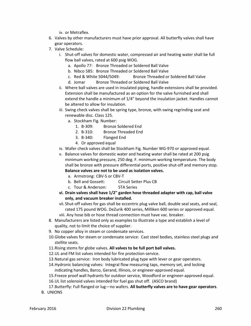
February 2016 Division 22 Plumbing 260
iv. or Metraflex. 6. Valves by other manufacturers must have prior approval. All butterfly valves shall have
gear operators. 7. Valve Schedule:
i. Shut-off valves for domestic water, compressed air and heating water shall be full flow ball valves, rated at 600 psig WOG.
a. Apollo 77: Bronze Threaded or Soldered Ball Valve b. Nibco 585: Bronze Threaded or Soldered Ball Valve c. Red & White 5044/5049: Bronze Threaded or Soldered Ball Valve d. Jomar Bronze Threaded or Soldered Ball Valve
ii. Where ball valves are used in insulated piping, handle extensions shall be provided. Extension shall be manufactured as an option for the valve furnished and shall extend the handle a minimum of 1/4" beyond the insulation jacket. Handles cannot be altered to allow for insulation.
iii. Swing check valves shall be spring type, bronze, with swing regrinding seat and renewable disc. Class 125.
a. Stockham Fig. Number: 1. B-309: Bronze Soldered End 2. B-310: Bronze Threaded End 3. B-340: Flanged End 4. Or approved equal
iv. Wafer check valves shall be Stockham Fig. Number WG-970 or approved equal. v. Balance valves for domestic water and heating water shall be rated at 200 psig
minimum working pressure, 250 deg. F. minimum working temperature. The body shall be bronze with pressure differential ports, positive shut-off and memory stop. Balance valves are not to be used as isolation valves.
a. Armstrong: CBV-S or CBV-T b. Bell and Gossett: Circuit Setter Plus CB c. Tour & Anderson: STA Series
vi. Drain valves shall have 1/2" garden hose threaded adapter with cap, ball valve only, and vacuum breaker installed.
vii. Shut-off valves for gas shall be eccentric plug valve ball, double seal seats, and seal, rated 175 pound WOG. DeZurik 400 series, Milliken 600 series or approved equal.
viii. Any hose bib or hose thread connection must have vac. breaker. 8. Manufacturers are listed only as examples to illustrate a type and establish a level of
quality, not to limit the choice of supplier. 9. No copper alloy in steam or condensate services. 10. Globe valves for steam or condensate service: Cast steel bodies, stainless steel plugs and
stellite seats. 11. Rising stems for globe valves. All valves to be full port ball valves. 12. UL and FM list valves intended for fire protection service. 13. Natural gas service: Iron body lubricated plug type with lever or gear operators. 14. Hydronic balancing valves: Integral flow measuring taps, memory set, and locking
indicating handles, Barco, Gerand, Illinois, or engineer-approved equal. 15. Freeze proof wall hydrants for outdoor service, Woodford or engineer-approved equal. 16. UL list solenoid valves intended for fuel gas shut off. (ASCO brand) 17. Butterfly: Full flanged or lug—no wafers. All butterfly valves are to have gear operators.
B. UNIONS

February 2016 Division 22 Plumbing 261
1. Make connections at each piece of equipment with unions or flanges located for quick/easy disconnect for maintenance. Provide unions or flanges on:
i. Control Valves. ii. Equipment. iii. Meters. iv. Tanks.
2. Unions shall be installed at the coil connection for all unit ventilators. 3. Use the same materials and finish as the piping system. 4. Use dielectric nipples or flanges where copper or brass piping is connected to ferrous
piping or equipment. Epco Model FX, FB, EA. (All junctions of dissimilar metals) i. Dielectric nipples are to be used between steel and copper piping on hydronic and
chilled systems. ii. Dielectric unions are not to be used.
5. Unions and flanges are not required at equipment where flanged valves, strainers, control valves, etc., are used.
6. Omit unions and flanges in straight pipe runs or in concealed locations, except for flanged valve applications.
7. Union Schedule: i. Copper Piping:
a. All pipe sizes: Copper, ground joint union. Chase 402, Mueller WC407. ii. Hot-water heating, compressed air, natural gas.
a. Piping sizes 2" and smaller: 1. Malleable iron unions with ground joint brass to iron seat, 150 pound
working steam pressure. Grinnell 463, Stockham 694, black or galvanized. 2. Flexible gas connectors shall not be used. All ground joint unions must have
upstream shutoff. Connectors to be heavy duty, quick couple type as approved by CITY OF FORT COLLINS and the Engineer, except: i. Commercial grade braided gas connectors, with tether, shall be used for
gas-fired cooking equipment in kitchens (as required by Health Dept,) Examples are ranges, fryers, etc.
ii. Stainless Steel braided flex gas connectors required on generators. 3. Pipe sized 2-1/2" and larger (welded):
i. Forged steel flanges, 150 pound, welding neck or slip on with raised faces and 1/16" Garlock 9712 EPDM or Gylon Style 3565 Envelon gaskets and carbon steel bolts. Grinnell Fig. 1911 and 1921. Tube Turn Series 15, Walworth.
4. Pipe sizes 2-1/2" and larger (screwed): i. Cast iron flanged unions, threaded, galvanized or black, 175-pound
water, gasket type with carbon steel bolts. Grinnell 487, Stockham 489. Part 3: Execution 3.01 Preparation 3.02 Installation:
A. Valving: 1. Provide valves on all water and gas piping lines before they enter and after they leave a
basement, crawl space or trench. Install shut off valves for all plumbing groups. Install an accessible wrench operated plug valve on the gas main outside before it enters the building.
3.03 Cleaning and Protection

February 2016 Division 22 Plumbing 262
END OF SECTION 22 05 23
SECTION 22 05 29 – HANGERS AND SUPPORTS FOR PLUMBING PIPING AND EQUIPMENT
Part 1: General 1.01 Summary
A. Types of supports and anchors specified in this section include the following: 1. Horizontal-Piping Hangers and Supports. 2. Vertical-Piping Clamps. 3. Hanger-Rod Attachments. 4. Building Attachments. 5. Saddles and Shields. 6. Spring Hangers and Supports. 7. Miscellaneous Materials. 8. Roof Equipment Supports. 9. Anchors. 10. Equipment Supports.
B. Supports and anchors furnished as part of factory- fabricated equipment are specified as part of equipment assembly in other Division 23 sections.
1.02 Related Sections 1.03 Definitions 1.04 Submittals Required
A. Product Data: B. Shop Drawings: C. Product certificates. D. Maintenance Data:
1.05 Quality Assurance A. Manufacturer's Qualifications: Firms regularly engaged in manufacture of supports and
anchors, of types and sizes required, whose products have been in satisfactory use in similar service for not less than 5 years.
1.06 Scheduling 1.07 Delivery, Storage, and Handling 1.08 Regulatory Requirements Part 2: Products 2.01 Manufacturers
A. Manufacturer: Subject to compliance with requirements, provide products by one of the following: 1. Pipe Hangers and Supports:
i. B-Line Systems Inc. ii. Carpenter and Patterson, Inc. iii. Fee & Mason Mfg. Co.; Div. Figgie International iv. Grinnell Corp. v. PHD Manufacturing, Inc.

February 2016 Division 22 Plumbing 263
vi. Elcen Metal Products Company vii. Michigan Hanger Company viii. ITT Grinnell Corp. ix. Unistrut Metal Framing Systems x. Hubbard Enterprises (Supports for domestic water piping) xi. Specialty Products Co. (Supports for domestic water piping.
2. Saddles and Shield: i. Grinnell Corp. ii. Pipe Shields, Inc. iii. Insulation Pipe Supports Manufacturing iv. Insulated Saddle Shield Insert Product Inc. v. Future Market Industries, Inc. vi. Michigan Hanger Company vii. Component Products Co. viii. Value Engineered Products, Inc.
3. Roof Equipment Supports: i. Custom Curb, Inc. ii. Pate Co. iii. Thycurb Div.; Thybar Corp.
2.02 Products A. General
1. Provide pipe hangers, supports, anchors, and guides as specified herein, conforming to manufacturer's standardization society specification SP-69. Locate at changes in direction and at concentrated loads. Hanger design shall permit vertical adjustment and lateral movement to allow pipe expansion. Double nut hangers where piping is subject to water hammer, i.e. near flush valves and solenoid valves. All insulated pipe will have insulation inserts with shield at all hanger locations.
2. Bear hot piping directly on hangers or on insulation shields and cold piping on insulation, shielded as described under article for insulation. All insulated pipe will have insulation inserts with shield at all hanger locations.
3. Provide pipe hangers of ample diameter for cold piping insulation and vapor barrier jacket. 4. Use carbon steel adjustable hangers as follows:
i. Steel / cast iron, 2-1/2" and larger. Grinnell Fig. 260, Fee and Mason Fig. 239, Elcen Fig. 12.
ii. Steel, plastic and cast iron, 2" and smaller. Grinnell Fig. 69, Fee and Mason Fig. 400, Elcen Fig. 202.
iii. Copper pipe 2" and smaller. Grinnell Fig. CT-69, Fee and Mason Fig. 389, Elcen Fig. 389.
5. Three or more pipes may be supported on trapeze hangers. Isolate copper pipe from bearing on the cross member with an electrically insulating material.
i. Trapeze hangers shall be "Unistrut" or equal, double channel with drop rods. Where pipes are to be supported on trapeze hanger, provide "Unistrut" or equal speed clamps. Isolate copper pipe from cross member as specified above. Clamps may be placed over insulation.
6. Support horizontal steel piping per SP-69 or as follows, whichever is more stringent: Pipe Size Rod Diameter Maximum Spacing Up to 1-1/4" 3/8" 8 ft. 1-1/2" to 3-1/2" 1/2" 8 ft.
February 2016 Division 22 Plumbing 264
4" & 5" 5/8" 12 ft. 6" 3/4" 12 ft.
7. Support horizontal copper piping per SP-69 or as follows, whichever is more stringent: Nom. Tubing Size Rod Diameter Maximum Spacing Up to 1-1/2" 3/8" 6 ft. 2" to 2-1/2" 3/8" 8 ft. 3" 1/2" 9 ft.
8. Support horizontal hub and spigot pipe at every hub, 10 ft. max. spacing. 9. Support horizontal hubless cast iron pipe at every joint and at each horizontal branch
connection. Sway brace to prevent shear. 10. Support plastic every 4 feet. 11. Support vertical piping as follows:
i. Steel: Every other floor. ii. Cast Iron and Copper: Every floor, 10 ft. max. intervals. iii. Plastic: Every floor plus 5' spacing between floors.
12. In existing concrete frame structures, support pipe hangers from the sides only of beams or joists using austempered ramset fasteners or Phillips red head concrete anchors. Follow manufacturer's load recommendations.
13. In reinforced concrete structures, support pipe hangers and ducts from concrete inserts as follows:
i. Loads to 400 pounds light weight concrete inserts, Grinnell Fig. 285, Elcen Fig. 86, Fee and Mason Fig. 186.
ii. Loads 400 to 1430 pounds: Universal concrete insert, Grinnell Fig. 282, Elcen Fig. 64, Fee and Mason Fig. 2570.
iii. Set inserts in concrete forms obtain approval of their locations in ample time to permit pouring of concrete as scheduled; provide reinforcing rods for pipe sizes over 3" and for duct sizes as directed.
iv. In areas where concrete slab will form finished ceiling, take care to have inserts finish flush with concrete slab surface and to make neat appearance.
14. In steel framed structures, support pipe hangers from beam clamps, attachments and brackets bolted to steel joists or beams. Use steel washer plates for pipe supported from steel joists, Grinnell Fig. 60, Elcen Fig. 84, Fee and Mason Fig. 91. Hang near joist panel point, where possible. Bolting to steel deck is prohibited. Hang pipes over 5" diameter from more than 1 joist. Absolutely no piping shall be supported directly on the roof joists.
15. Hanging from one pipe to another is prohibited. 16. Anchor pipe with steel collars or saddles fitted with lugs and bolts, Keflex BA or Adsco.
Install anchor braces and turnbuckles as required for stability. Attachment in a manner injurious to the structure is prohibited.
B. PIPE HANGERS & SUPPORTS 1. Hangers and support components shall be factory fabricated of materials, design, and
manufacturer complying with MSS SP-58. i. Components shall have galvanized coatings where installed for piping and equipment
that will not have field-applied finish. ii. Pipe attachments shall have nonmetallic coating for electrolytic protection where
attachments are in direct contact with copper tubing. 2. Adjustable Clevis Hanger: MSS Type 1.
i. Steel Pipe, size 3/8" thru 12", Grinnell fig. 260. ii. Copper Pipe, size 1/2" thru 4", Grinnell fig. CT-65.
February 2016 Division 22 Plumbing 265
iii. Cast Iron Pipe, size 4" thru 24", Grinnell fig. 590. 3. Adjustable Swivel Ring: MSS Type 10.
i. Steel Pipe, size 1/2" thru 2", Grinnell fig. 69; size 2-1/2" thru 8", Grinnell figs. 69 or 70.
ii. Copper Pipe, size 1/2" thru 4", Grinnell fig. CT-69. 4. Pipe Clamps: MSS Type 8.
i. Steel Pipe, size 3/4" thru 20", Grinnell fig. 261. ii. Copper Pipe, size 1/2" thru 4", Grinnell fig. CT-121.
5. U Bolts: MSS Type 24. i. Steel Pipe, size 1/2" thru 36", Grinnell fig. 137. ii. Copper Pipe, size 1/2" thru 8", Grinnell fig. 137C.
6. Straps: MSS Type 26. i. Steel Pipe, size 1/2" thru 4", Grinnell fig. 262.
7. Pipe Stanchion Saddle: MSS Type 37. i. Steel Pipe, size 4" thru 12", Grinnell fig. 259.
8. Yoke & Roller Hanger: MSS Type 43 i. 2-1/2" thru 20", Grinnell fig. 181.
9. Hanger Rods: Continuous threaded steel. 10. Hangers:
i. Hot Pipes: a. 1/2" through 1-1/2": Adjustable wrought steel ring. b. 2" through 5": Adjustable wrought steel clevis. c. 6" and Over: Adjustable steel yoke and cast iron roll.
ii. Cold Pipes: a. 1/2" through 1-1/2": Adjustable wrought steel ring. b. 2" and Over: Adjustable wrought steel clevis.
iii. Multiple or Trapeze: Structural steel channel (with web vertical), with welded spacers and hanger rods. Provide cast iron roll and stand for hot pipe sizes six inches and over. Provide hanger rods one size larger than for largest pipe in trapeze. If the deflection at center of trapeze exceeds 1/360 of the distance between the end hangers, install an additional hanger at mid-span or use a larger channel. On trapeze type hangers, provide pipe clamps on all piping. Clamps on insulated piping shall be sized for the insulation O.D. to allow for pipe movement.
11. Wall Supports for Horizontal Pipe: i. 1/2" through 3-1/2": Steel offset hook. ii. 4" and Over: Welded steel bracket and wrought steel clamp. Provide adjustable
steel yoke and cast iron roll for hot pipe 200oF and over and sizes six inches and over. 12. Upper Attachments:
i. For attaching hanger rods to structural steel I-beams: a. Provide adjustable beam clamp, Elcen No. 95 with No. 235 rod socket or equal.
Attach to bottom flange of beam. ii. For attaching hanger rods to bar joists:
a. When bottom chord is constructed of structural steel angles, provide Elcen No. 84H square washer or equal with nut. Place hanger rod between backs of the two angles and support with the washer on top of the angles. Spot weld washer to angles.
b. When bottom chord is constructed of round bars, provide Elcen No. 137 bar joint washer or equal.

February 2016 Division 22 Plumbing 266
C. FLOOR, WALL, AND CEILING PLATES 1. Plates shall be installed on all exposed pipe passing through walls, floors, or ceilings.
Plates shall be as manufactured by Ritter Pattern and Casting Company, 120 Walker Street, New York, New York 10013, or approved equal, chrome plated steel plates with set screw and concealed hinge. Cut plates to fit flush at close-spaced piping locations.
D. SADDLES AND THERMAL SHIELD INSERTS 1. General: Provide saddles [thermal shield inserts] under all insulated piping hangers and
thermal shield inserts on all piping through floors, wall and roof construction penetrations. Size saddles and shields for exact fit to mate with pipe insulation or a minimum of 1" thick for uninsulated pipe thermal shield inserts.
2. Protection Saddles: MSS Type 39; fill interior voids with segments of insulation matching adjoining insulation.
i. Grinnell Figs 160-165. 3. Protection Shields: MSS Type 40; of length recommended by manufacturer to prevent
crushing of insulation. i. Grinnell Fig. 167.
4. Thermal Shield Inserts: Provide 100-psi average compressive strength, waterproof, asbestos free calcium silicate, encased with a sheet metal enclosure. Insert and shield shall cover the entire circumference or the bottom half circumference of the pipe and shall be of length recommended by the manufacturer for pipe size and thickness of insulation or the thickness of the wall, roof or floor construction.
E. MISCELLANEOUS MATERIALS 1. Steel Plates, Shapes, and Bars: ASTM A 36. 2. Heavy-Duty Steel Trapezes: Fabricate from steel shapes selected for loads required; weld
steel in accordance with AWS standards. F. ROOF EQUIPMENT SUPPORTS
1. General: Construct roof equipment supports using minimum 18-ga galvanized steel with fully mitered and welded corners, 3" cant, internal bulkhead reinforcing, integral base plates, pressure treated wood nailer, 18-ga galvanized steel counterflashing and rigid insulation.
2. Configuration: Compensate for slope in roof so top of support is dead level. Part 3: Execution 3.01 Preparation
A. INSPECTION 1. Examine areas and conditions under which supports and anchors are to be installed. Do
not proceed with work until unsatisfactory conditions have been corrected in manner acceptable to Installer.
3.02 Installation A. INSTALLATION OF BUILDING ATTACHMENTS
1. Install building attachments on structural steel. Space attachments within maximum piping span length indicated in MSS SP-69. Install additional attachments at concentrated loads, including valves, flanges, guides, strainers, expansion joints, and at changes in direction of piping.
B. INSTALLATION OF HANGERS AND SUPPORTS 1. Install hangers, supports, clamps and attachments to support piping properly from building
structure; comply with MSS SP-69 and SP-89. Arrange for grouping of parallel runs of horizontal piping to be supported together on field fabricated, heavy-duty trapeze hangers
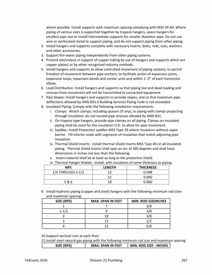
February 2016 Division 22 Plumbing 267
where possible. Install supports with maximum spacing complying with MSS SP-69. Where piping of various sizes is supported together by trapeze hangers, space hangers for smallest pipe size or install intermediate supports for smaller diameter pipe. Do not use wire or perforated metal to support piping, and do not support piping from other piping.
2. Install hangers and supports complete with necessary inserts, bolts, rods, nuts, washers and other accessories.
3. Support fire-water piping independently from other piping systems. 4. Prevent electrolysis in support of copper tubing by use of hangers and supports which are
copper plated, or by other recognized industry methods. 5. Install hangers and supports to allow controlled movement of piping systems, to permit
freedom of movement between pipe anchors, to facilitate action of expansion joints, expansion loops, expansion bends and similar units and within 1'-0" of each horizontal elbow.
6. Load Distribution: Install hangers and supports so that piping live and dead loading and stresses from movement will not be transmitted to connected equipment.
7. Pipe Slopes: Install hangers and supports to provide slopes, and so that maximum pipe deflections allowed by ANSI B31.9 Building Services Piping Code is not exceeded.
8. Insulated Piping: Comply with the following installation requirements. i. Clamps: Attach clamps, including spacers (if any), to piping with clamps projecting
through insulation; do not exceed pipe stresses allowed by ANSI B31. ii. On trapeze type hangers, provide pipe clamps on all piping. Clamps on insulated
piping shall be sized for the insulation O.D. to allow for pipe movement. iii. Saddles: Install Protection saddles MSS Type 39 where insulation without vapor
barrier. Fill interior voids with segments of insulation that match adjoining pipe insulation.
iv. Thermal Shield Inserts: Install thermal shield inserts MSS Type 40 on all insulated piping. Thermal shield inserts shall span an arc of 360 degrees and shall have dimensions in inches not less than the following:
v. Insert material shall be at least as long as the protective shield. vi. Thermal Hanger Shields: Install, with insulation of same thickness as piping.
NPS LENGTH THICKNESS 1/4 THROUGH 3-1/2 12 0.048
12 0.060 5 & 6 18 0.060
9. Install hydronic piping (copper and steel) hangers with the following minimum rod sizes
and maximum spacing: SIZE (NPS) MAX. SPAN IN FEET MIN. ROD SIZEINCHES
1 7 3/8 1-1/2 9 3/8
2 10 3/8 3 12 1/2 4 12 5/8
10. Support vertical runs at each floor. 11. Install steel natural gas piping with the following minimum rod size and maximum spacing:
SIZE (NPS) MAX. SPAN IN FEET MIN. ROD SIZE - INCHES
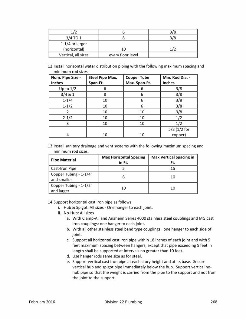
February 2016 Division 22 Plumbing 268
1/2 6 3/8 3/4 TO 1 8 3/8
1-1/4 or larger (horizontal) 10 1/2
Vertical, all sizes every floor level
12. Install horizontal water distribution piping with the following maximum spacing and minimum rod sizes:
Nom. Pipe Size -Inches
Steel Pipe Max. Span-Ft.
Copper Tube Max. Span-Ft.
Min. Rod Dia. -Inches
Up to 1/2 6 6 3/8 3/4 & 1 8 6 3/8 1-1/4 10 6 3/8 1-1/2 10 6 3/8
2 10 10 3/8 2-1/2 10 10 1/2
3 10 10 1/2
4 10 10 5/8 (1/2 for
copper)
13. Install sanitary drainage and vent systems with the following maximum spacing and minimum rod sizes:
Pipe Material Max Horizontal Spacing in Ft.
Max Vertical Spacing in Ft.
Cast-Iron Pipe 5 15 Copper Tubing - 1-1/4" and smaller 6 10
Copper Tubing - 1-1/2" and larger 10 10
14. Support horizontal cast iron pipe as follows:
i. Hub & Spigot: All sizes - One hanger to each joint. ii. No-Hub: All sizes
a. With Clamp-All and Anaheim Series 4000 stainless steel couplings and MG cast iron couplings: one hanger to each joint.
b. With all other stainless steel band type couplings: one hanger to each side of joint.
c. Support all horizontal cast iron pipe within 18 inches of each joint and with 5 feet maximum spacing between hangers, except that pipe exceeding 5 feet in length shall be supported at intervals no greater than 10 feet.
d. Use hanger rods same size as for steel. e. Support vertical cast iron pipe at each story height and at its base. Secure
vertical hub and spigot pipe immediately below the hub. Support vertical no-hub pipe so that the weight is carried from the pipe to the support and not from the joint to the support.

February 2016 Division 22 Plumbing 269
15. Provide copper or copper plated hangers and supports for copper piping or provide sheet lead packing between hanger or support and piping.
16. Place a hanger within one foot (0.305 m) of each horizontal elbow. 17. Use hangers which are vertically adjustable 1-1/2 inch (38.1 mm) minimum after piping is
erected. 18. Support vertical steel and copper piping at every story height but at not more than 15 foot
intervals for steel and 10 feet for copper. 19. Where several pipes can be installed in parallel and at same elevation, provide uni-strut
trapeze hangers. Provide pipe clamps on all pipes supported on trapeze hangers, sized for the O.D. of the pipe insulation to allow for pipe movement.
20. Where practical, support riser piping independently of connected horizontal piping. 21. All insulated pipes shall have thermal shield insert [insulation protection saddles] at all
support points. All piping shall have thermal shield inserts at each penetration thru wall, floor and roof.
22. Each pipe drop to equipment shall be adequately supported. All supporting lugs or guides shall be securely anchored to the building structure.
23. Install all couplings with torque wrench, torqued to inch pounds as specified by the manufacturer.
24. Securely anchor and support plumbing domestic water piping in chases or walls. Use factory manufactured clamps and brackets connected to fixture carriers, waste/vent piping or brackets connected to studs. Wires or straps will not be permitted.
i. When copper supplies are connected to flush valves, support the tubing by the studs or by a fixture carrier, not by clamping to waste/vent piping.
ii. Prevent copper tubes from making contact with steel brackets using duct tape, fire retardant polyethylene inserts or other dielectric insulating material.
iii. Place supports every ten feet on vertical pipe and every five feet on horizontal pipe. 25. Hang all insulated pipe at the point of support in the following manner:
i. Thermal Shield Insert: Provide thermal shield insert of the same thickness as adjoining insulation for insulated pipe. The entire 360 degrees shall be waterproof, asbestos free, calcium silicate.
a. If the pipe hanger spacing exceeds ten (10) feet or if there are to be pipe rollers, utilize a double thick shield on bearing surface.
b. On domestic cold water, chilled water and horizontal roof drain pipe the thermal shield insert shall extend 2 inches beyond the construction material and the sheet metal shield shall span an arc of 360 degrees. All hangers shall be properly sized to accommodate the thermal shield insert and no hanger shall penetrate or crush any of the insulating material.
26. Install anchors and fasteners in accordance with manufacturer's recommendations and the following:
i. In the event a self-drilling expansion shield or machine bolt expansion shield is considered to have been installed improperly, the Contractor shall make an acceptable replacement or demonstrate the stability of the anchor by performing an on-site test under which the anchor will be subjected to a load equal to twice the actual load.
ii. Powder-driven fasteners may be used only where they will be concealed after the construction is complete. Where an occasional fastener appears to be improperly installed, additional fastener(s) shall be driven nearby (not closer than 6 inches) in undisturbed concrete. Where it is considered that many fasteners are improperly
February 2016 Division 22 Plumbing 270
installed, the Contractor shall test load any 50 successively driven fasteners. If 10 percent or more of these fasteners fail, the Contractor shall utilize other fastening means as approved and at no additional cost to the Owner.
iii. Hangers for piping and ducts shall be attached to cellular steel floor decks with steel plates and bolted rod conforming to the steel deck manufacturer's requirements. Where the individual hanger load exceeds the capacity of a single floor deck attachment, steel angles, beams or channels shall be provided to span the number of floor deck attachments required.
iv. Welding may be used for securing hangers to steel structural members. Welded attachments shall be designed so that the fiber stress at any point of the weld or attachment will not exceed the fiber stress in the hanger rod.
C. SLEEVES AND SEALS 1. General:
i. Encase all insulated pipes penetrating fire rated walls and floors in 360 degree metal-shielded insulation inserts as manufactured by Pipe Shields, Inc. or equal. Extend insulation insert on all domestic cold water, chilled water and refrigerant lines 1" beyond sheet metal shield.
2. Pipes: i. Pipes
a. Pipes penetrating fire rated concrete or masonry construction, whether insulated or not, shall be provided with sheet metal or pipe sleeves fitted into place at time of construction. In poured concrete, the sleeves shall be steel pipe with a full circle, continuously welded water stop plate to also act as a sleeve anchor. When installing Link-Seal (see paragraph f) the sleeve and Link-Seal shall be of matched sizes. Otherwise, sleeves shall be of such size to provide all around clearance of 1/4" to 1". Seal entire space between pipe and sleeve with fire stopping as specified in paragraph A.
b. Sleeves in non-fire rated or non-bearing walls, floors or ceilings, new or existing construction, shall be steel pipe or galvanized sheet metal with lock-type longitudinal seam. Pack all open spaces on each end with mineral wood or other non-combustible material, positively fastened in place. Asbestos is not acceptable.
c. Where a pipe of any description passes through a concrete floor, the sleeve shall extend at least 2" above the finished floor, except when using the ProSet Systems.
d. At Contractor's option, where uninsulated pipes penetrate cast-in-place concrete floors, the "ProSet Systems", Atlanta, Georgia, sleeving may be employed.
e. For pipes penetrating foundation walls, water-proofing membrane floors or other places where water leakage could be encountered, install Link-Seal wall sleeves by Thunderline Corporation in manner recommended by the manufacturer.
3. Seals: i. General:
a. Seal all holes or voids where mechanical systems penetrate fire rated floors and walls with a fire stopping sealant having a fire rating equal to or greater than that of the construction being penetrated, but not less than 2 hours. The sealant shall meet the requirements of ASTM E-814, ASTM E-119 and UL-1479. It shall

February 2016 Division 22 Plumbing 271
be installed with strict adherence to the manufacturer's instructions and according to the product's UL Laboratory listing. The use of asbestos in any form is not permitted.
ii. Types of Seals: a. Intumescent (3M Company CP25 Caulk and 303 Putty) b. Expanding Foam (Dow Corning 3-6548 Silicone RTV Foam) c. Refractory Putty (SOHIO Carborundum Fire Putty)
iii. Method of Use: a. Intumescent type: For insulated pipe, install insulation through the sleeve with
a continuous vapor seal if required. Install intumescent seal in the annular space between the pipe insulation and the pipe sleeve. Refer to manufacturer's data sheets for maximum annular space allowable and thickness of material required to maintain the rating of the construction being penetrated in conformance with applicable UL Fire Stop Classification for the product.
b. Expanding foam: For insulated pipe, terminate the insulation on both sides of the wall or floor being penetrated and fill the space between the construction and the bare pipe with the foam. For uninsulated pipe, continue pipe through the penetration and proceed as with insulated pipe.
c. Refractory putty: For insulated pipe, provide a 360 degree metal-shielded calcium silicate insulation insert as specified in paragraph "A." Pack and seal the entire space between shield and sleeve with refractory putty. When sealing bare pipe, omit the metal-shielded insert.
iv. Escutcheons: a. In finished parts of the building, after painting is completed, install chromium
plated escutcheons on all pipes passing through walls and floors. D. METAL FABRICATION
1. Cut, drill, and fit miscellaneous metal fabrications for pipe anchors and equipment supports. Install and align fabricated anchors.
2. Fit exposed connections together to form hairline joints. Field weld connections that cannot be shop welded because of shipping size limitations.
3. Field Welding: For procedures of manual shielded metal-arc welding, appearance and quality of welds made, methods used in correcting welding work, comply with those listed on project drawings and the following:
i. Use materials and methods that minimize distortion and develop strength and corrosion resistance of base metals.
ii. Obtain fusion without undercut or overlap. iii. Remove welding flux immediately. iv. Finish welds at exposed connections so no roughness shows after finishing and
contours at welded surfaces match adjacent contours. E. ADJUSTING
1. Hanger Adjustment: Adjust hangers to distribute loads equally on attachments and to achieve slope of pipe.
2. Touch-Up Painting: Immediately after erection of anchors and supports, clean field welds and abraded areas of shop paint and paint exposed areas with same material as used for shop painting to comply with SSPC-PA-1 requirements for touch-up of field-painted surfaces.
i. Touch-Up Painting: Cleaning and touch-up painting of field welds, bolted connections, and abraded areas of the shop paint on miscellaneous.

February 2016 Division 22 Plumbing 272
3. For galvanized surfaces clean welds bolted connections and abraded areas and apply galvanizing repair paint to comply with ASTM A 780.
3.03 Cleaning and Protection
END OF SECTION 22 05 29
SECTION 22 05 48 – VIBRATION AND SEISMIC CONTROL FOR PLUMBING PIPING AND EQUIPMENT
Part 1: General 1.01 Summary
A. Types of vibration control products specified in this section include the following: 1. Neoprene Pads. 2. Vibration Isolation Springs. 3. All-Directional Anchors. 4. Neoprene Mountings. 5. Spring Isolators, Free-Standing. 6. Spring Isolators, Vertically-Restrained. 7. Thrust Restraints. 8. Fabricated Equipment Bases. 9. Isolation Hangers. 10. Flexible Pipe Connectors.
1.02 Related Sections 1.03 Definitions 1.04 Submittals Required
A. Product Data: B. Shop Drawings: C. Maintenance Data:
1.05 Quality Assurance A. Manufacturer's Qualifications: Firms regularly engaged in manufacture of vibration control
products, of type, size, and capacity required, whose products have been in satisfactory use in similar service for not less than 5 years. 1. Obtain vibration control products from single manufacturer. 2. Engage manufacturer to provide technical supervision of installation of support isolation
units produced, and of associated inertia bases (if any). 1.06 Scheduling 1.07 Delivery, Storage, and Handling 1.08 Regulatory Requirements Part 2: Products 2.01 Manufacturers
A. Manufacturer: Subject to compliance with requirements, provide products by one of the following: 1. Vibration Control Products: 2. Mason Industries, Inc.

February 2016 Division 22 Plumbing 273
3. Peabody Noise Control, Inc. 2.02 Products
A. VIBRATION CONTROL MATERIALS AND SUPPORT UNITS 1. Neoprene Pads: Oil-resistant neoprene sheets of manufacturer's standard hardness and
cross-ribbed or waffled pattern. i. Mason Industries Type W.
2. Vibration Isolation Springs: Wound-steel compression springs, of high-strength, heat-treated, spring alloy steel with outside diameter not less than 0.8 times operating height; with lateral stiffness not less than vertical stiffness and designed to reach solid height before exceeding rated fatigue point of steel.
i. Color coated springs for ease of identification. ii. Spring shall have a minimum of 50% additional travel to solid.
3. Neoprene Mountings: Provide neoprene mountings consisting of neoprene element bonded between 2 steel plates that are neoprene-covered to prevent corrosion. Provide minimum rated deflection of 0.35". Provide threaded hole in upper plate and 2 holes in base plate for securing to equipment and to substrate.
i. Mason Industries Type ND. 4. Spring Isolators, Free-Standing: Provide vibration isolation spring Type C between top and
bottom loading plates, and with pad-type Type B isolator bonded to bottom of bottom loading plate. Include studs or cups to ensure centering of spring on plates. Include leveling bolt with lock nuts and washers, centered in top plate, arranged for leveling and anchoring supported equipment as indicated.
i. Include holes in bottom plate for bolting unit to substrate as indicated. ii. Mason Industries Type SLFH.
5. Spring Isolators, Vertically-Restrained: Provide spring isolators Type C in housing that includes vertical limit stops. Design housing to act as blocking during erection, and with installed height and operating height being equal. Maintain 1/2" minimum clearance around restraining bolts, and between housing and springs. Design so limit stops are out of contact during normal operation.
i. Mounting used out of doors shall be hot dipped galvanized, spring shall be cadmium plated.
ii. Mounting used out of doors shall have certified calculation by a registered professional engineer showing ability to withstand 109 MPH wind load in 3 principal axis.
iii. Mason Industries Type SLR. 6. Thrust Restraints: Provide horizontal thrust restraints consisting of spring elements in
series with neoprene pad. Select spring deflection same as for equipment loading. Design so thrust restraints can be pre-set and adjusted in field. Attach horizontal restraints at centerline of thrust and symmetrically on either side of unit.
i. Provide same deflection as isolated equipment. ii. Select load to provide 1/4" maximum displacement under full system operating
pressure. iii. Mason Industries Type WBI.
7. Isolation Hangers: Hanger units formed with brackets and including manufacturer's standard compression isolators. Design brackets for 5 times rated loading of units. Fabricate units to accept misalignment of 15 deg. off center in any direction before contacting hanger box, and for use with either rod or strap type members, and including acoustical washers to prevent metal-to-metal contacts.

February 2016 Division 22 Plumbing 274
i. Provide vibration isolation spring Type C with cap in lower pad-type isolator rubber hanger element in bottom, securely retained in unit.
ii. Provide neoprene element, with minimum deflection of 0.35", securely retained in hanger box.
iii. Mason Industries Type 30N. 8. Riser Isolators: Suspend risers from, or support risers by, spring hangers Type ND or spring
isolators Type F. Wherever possible, anchor risers at central point with resilient anchors, Type D. Provide hanger or mounting deflection of 0.75" except in those expansion locations where additional deflection is required to limit deflection or load changes to +25% of initial deflection. Provide sliding guides held in position by resilient anchors, located between anchor points and end of piping.
9. Flexible Pipe Connectors: i. For non-ferrous piping, provide bronze hose covered with bronze wire braid with
copper tube ends or bronze flanged ends, braze-welded to hose. a. Mason Industries Type BBF.
ii. Flexible Pipe Connectors: Provide EDPM construction consisting of multiple plies of nylon tire cord fabric and elastomer molded and cured in hydraulic rubber presses. Provide straight connector, rated at 125 psi at 220 deg. F (104 deg. C).
a. Mason Industries Type MFNC. Part 3: Execution 3.01 Preparation
A. INSPECTION 1. Examine areas and conditions under which vibration control units are to be installed. Do
not proceed with work until unsatisfactory conditions have been corrected in manner acceptable to Owner or his representative.
B. PERFORMANCE OF ISOLATORS 1. Manufacturer's Recommendations: Comply with manufacturer's recommendations for
selection and application of vibration isolation materials and units to achieve minimum static deflection and displacement requirements.
C. APPLICATIONS 1. General: Select vibration control products in accordance with ASHRAE Handbook, 1991
HVAC Applications Volume, Chapter 42 "Sound and Vibration Control", Table 34. 2. Piping: For piping connected to equipment mounted on vibration control products, install
isolation hangers Type N, for first 3 points of support for pipe sizes 4" and less, for first 4 points of support for pipe sizes 6" through 8", and for first 6 points of support for pipe sizes 10" and over.
i. Where applicable, apply restraint system in accordance with SMACNA GFSR 1982. 3. Fan Sets: All fan sets should have thrust restraints when operating over 2" W.C. S.P. unless
they are mounted on a concrete inertia base in which case the inertia base will not allow fan movement. The fan position at operating and stop positions should not move more than 1/4" displacement at these two conditions.
4. Earthquake Restraint: IF NEEDED install Type H seismic snubber. 3.02 Installation
A. INSTALLATION 1. General: Comply with manufacturer's instructions for installation and load application to
vibration isolation materials and units. Adjust to ensure that units do not exceed rated operating deflections or bottom out under loading, and are not short- circuited by other

February 2016 Division 22 Plumbing 275
contacts or bearing points. Remove space blocks and similar devices (if any) intended for temporary protection against overloading during installation.
2. Install units between substrate and equipment as required for secure operation and to prevent displacement by normal forces.
3. Adjust leveling devices as required to distribute loading uniformly onto isolators. Shim units as required where substrate is not level.
4. For air handling equipment, install thrust restraints and also wherever thrust exceeds 10% of equipment weight.
5. Locate isolation hangers as near overhead support structure as possible. 6. Weld riser isolator units in place as required to prevent displacement from loading and
operations. 7. Flexible Pipe Connectors: Install on equipment side of shutoff valves, horizontally and
parallel to equipment shafts wherever possible. B. EXAMINATION OF RELATED WORK
1. Installer of vibration isolation work shall observe installation of other work related to vibration isolation work, including work connected to vibration isolation work; and, after completion of other related work (but before equipment startup), shall furnish written report to Engineer listing observed inadequacies for proper operation and performance of vibration isolation work. Report shall cover, but not necessarily be limited to the following:
i. Equipment installations (performed as work of other sections) on vibration isolators. ii. Piping connections including flexible connections. iii. Ductwork connections including provisions for flexible connections. iv. Passage of piping and ductwork which is to be isolated through walls and floors.
2. Do not start-up equipment until inadequacies have been corrected in manner acceptable to vibration isolation installer.
C. DEFLECTION MEASUREMENTS 1. Upon completion of vibration isolation work, prepare report showing measured
equipment deflections theoretical floor deflection and isolation efficiency for each major item of equipment.
3.03 Cleaning and Protection A. ADJUSTING AND CLEANING
1. Clean each vibration control unit, and verify that each is working freely, and that there is no dirt or debris in immediate vicinity of unit that could possibly short- circuit unit isolation.
END OF SECTION 22 05 48
SECTION 22 05 53 – IDENTIFICATION FOR PLUMBING PIPING AND EQUIPMENT Part 1: General 1.01 Summary
A. Types of identification devices specified in this section include the following: 1. Plastic Pipe Markers. 2. Plastic Tape.

February 2016 Division 22 Plumbing 276
3. Plastic Duct Markers. 4. Valve Tags. 5. Valve Schedule Frames. 6. Engraved Plastic-Laminate Signs. 7. Equipment Markers. 8. Plasticized Tags.
1.02 Related Sections 1.03 Definitions 1.04 Submittals Required
A. Product Data: B. Schedules:
1.05 Quality Assurance A. Manufacturer's Qualifications: Firms regularly engaged in manufacturer of identification
devices of types and sizes required, whose products have been in satisfactory use in similar service for not less than 5 years.
B. Codes and Standards: 1. ANSI Standards: Comply with ANSI A 3.1 for littering size, length of color field, colors, and
viewing angles of identification devices. 1.06 Scheduling 1.07 Delivery, Storage, and Handling 1.08 Regulatory Requirements Part 2: Products 2.01 Manufacturers
A. Manufacturer: Subject to compliance with requirements, provide products by one of the following:
B. Mechanical Identification: 1. Westline Products 2. Brady (W.H.) Co.; Signmark Div. 3. Seton Name Plate Corp.
2.02 Products A. MECHANICAL IDENTIFICATION MATERIALS
1. General: Provide manufacturer's standard products of categories and types required for each application. Where more than single type is specified for application, selection is Installer's option, but provide single selection for each product category.
B. PLASTIC PIPE MARKERS 1. Snap-On Type: Provide manufacturer's standard pre-printed, semi-rigid snap-on, color-
coded pipe markers, complying with ANSI A13.1. 2. Insulation: Furnish 1" thick molded fiberglass insulation with jacket for each plastic pipe
marker to be installed on uninsulated pipes subjected to fluid temperatures of 125 deg. F. (52 deg. C.) or greater. Cut length to extend 2" beyond each end of plastic pipe marker.
3. Small Pipes: For external diameters less than 6" (including insulation if any), provide full-band pipe markers, extending 360 degrees around pipe at each location, fastened by one of the following methods:
i. Snap-on application of pre-tensioned semi-rigid plastic pipe marker. ii. Taped to pipe (or insulation) with color-coded plastic adhesive tape, not less than
3/4" wide; full circle at both ends of pipe marker, tape lapped 1-1/2".

February 2016 Division 22 Plumbing 277
4. Large Pipes: For external diameters of 6" and larger (including insulation if any), provide either full-band or strip-type pipe markers, but not narrower than 3 times letter height (and of required length), fastened by one of the following methods:
i. Steel spring or non-metallic fasteners. ii. Taped to pipe (or insulation) with color-coded plastic adhesive tape, not less than 1-
1/2" wide; full circle at both ends of pipe marker, tape lapped 3". iii. Strapped-to-pipe (or insulation) application of semi- rigid type, with manufacturer's
standard stainless steel bands. 5. Lettering: Comply with piping system nomenclature or to match existing building lettering
nomenclature system and abbreviate only as necessary for each application length. 6. Arrows: Print each pipe marker with arrows indicating direction of flow, either integrally
with piping system service lettering (to accommodate both directions), or as separate unit of plastic.
C. PLASTIC TAPE 1. General: Provide manufacturer's standard color-coded pressure-sensitive (self-adhesive)
vinyl tape, not less than 3 mils thick. 2. Width: Provide 1-1/2" wide tape markers on pipes with outside diameters (including
insulation, if any) of less than 6", 2-1/2" wide tape for larger pipes. 3. Color: Comply with ANSI A13.1.
D. VALVE TAGS 1. Brass Valve Tags: Provide 18-gauge polished brass valve tags with stamp-engraved piping
system abbreviation in 1/4" high letters and sequenced valve numbers 1/2" high, and with 5/32" hole for fastener.
i. Provide 1-1/2" diameter tags. ii. Fill tag engraving with black enamel.
2. Valve Tag Fasteners: Provide manufacturer's standard solid brass chain (wire link or beaded type), and solid brass S- hooks of the sizes required for proper attachment of tags to valves, and manufactured specifically for that purpose.
3. Access Panel Markers: Provide mechanical equipment identification as indicated in this section.
4. Identify all valves located above ceilings or behind access panels using Dymo embossing Tape punched with M-3 Dymomite hand embossing tool. Punch out 3/32" holes at each side of label and secure with Parker-Kalon self-taping screws in addition to adhesive.
E. VALVE SCHEDULE FRAMES 1. General: For each page of valve schedule, provide glazed display frame, with screws for
removable mounting on masonry walls. Provide frames of finished hardwood or extruded aluminum, with non-yellowing Plexi-glas.
F. EQUIPMENT IDENTIFICATION 1. Identify all key equipment, thermostats, controls, relays, dampers, valves, etc., using Dymo
embossing Tape punched with M-3 Dymomite hand embossing tool. Punch out 3/32" holes at each side of label and secure with Parker-Kalon self-taping screws in addition to adhesive.
i. Embossing tape equipment identification specified shall apply to identification labeling of mechanical equipment above ceilings or ceiling access doors. Provide this type of labeling at the ceiling to locate equipment from the occupied space.
2. For mechanical equipment exposed to view throughout the building, located in mechanical rooms or on the roof, provide engraved plastic laminate identification, black with white core, minimum size 2" x 4", with 1" high lettering. Equipment labels shall be fastened with
February 2016 Division 22 Plumbing 278
self-tabbing stainless steel screws. Provide contact-type permanent adhesive where screws should not penetrate the substrate.
G. PLASTICIZED TAGS 1. General: Manufacturer's standard pre-printed or partially pre-printed accident-prevention
tags, of plasticized card stock with matt finish suitable for writing, approximately 3-1/4" x 5-5/8", with brass grommets and wire fasteners, and with appropriate pre-printed wording including large- size primary wording (as examples; DANGER, CAUTION, DO NOT OPERATE).
H. LETTERING AND GRAPHICS 1. General: Provide numbers, lettering and wording as indicated and approved by the
Owner/Engineer for proper identification and operation/ maintenance of mechanical systems and equipment.
Part 3: Execution 3.01 Preparation 3.02 Installation
A. GENERAL INSTALLATION REQUIREMENTS 1. Coordination: Where identification is to be applied to surfaces which require insulation,
painting or other covering or finish, including valve tags in finished mechanical spaces, install identification after completion of covering and painting. Install identification prior to installation of acoustical ceilings and similar removable concealment.
B. PIPING SYSTEM IDENTIFICATION 1. General: Install pipe markers of the following type on each system and include arrows to
show normal direction of flow. 2. The requirement of labeling the mechanical system components and the quality of the
identification shall be emphasized in areas exposed to the student population, including, but not limited to, the stairways, the gymnasium, the cafeteria, the mechanical yard, the art room, the music room and roof areas visible from the second floor.
3. Plastic pipe markers. Install on pipe insulation segment where required for hot non- insulated pipes.
4. Locate pipe markers and color bands as follows wherever piping is exposed to view in occupied spaces, machine rooms, accessible maintenance spaces (shafts, tunnels, plenums) and exterior non-concealed locations.
5. Near each valve and control device. 6. Near each branch, excluding short take-offs for fixtures and terminal units; mark each pipe
at branch, where there could be question of flow pattern. 7. Near locations where pipes pass through walls or floors/ceilings, or enter non-accessible
enclosures. 8. At access doors, manholes and similar access points which permit view of concealed
piping. 9. Near major equipment items and other points of origination and termination. 10. Spaced intermediately at maximum spacing of 25' along each piping run, except reduce
spacing to 15' in congested areas of piping and equipment. 11. On piping above removable acoustical ceilings.
C. VALVE IDENTIFICATION 1. General: Provide valve tag on valves in each piping system. List each tagged valve in valve
schedule for each piping system. List valve tag locations on redline drawing at location of valves.

February 2016 Division 22 Plumbing 279
i. Building services main shut-off valves. ii. Each individual system main shut-off valves. iii. Each individual system floor shut-off valves. iv. Each individual system major branch shut-off valves.
2. Mount valve schedule frames and schedules in mechanical equipment rooms where directed by Owner.
D. MECHANICAL EQUIPMENT IDENTIFICATION: See Section 23 05 53. 3.03 Cleaning and Protection
A. Adjusting: Relocate any mechanical identification device which has become visually blocked by work of this division or other divisions.
B. Cleaning: Clean face of identification devices, and glass frames of valve charts.
END OF SECTION 22 05 53
SECTION 22 07 16 – PLUMBING EQUIPMENT INSULATION Part 1: General 1.01 Summary
A. Equipment Insulation: Fiberglass. Calcium Silicate 1.02 Related Sections 1.03 Definitions 1.04 Submittals Required
A. Product Data: B. Samples:
1.05 Quality Assurance 1.06 Scheduling 1.07 Delivery, Storage, and Handling 1.08 Regulatory Requirements Part 2: Products 2.01 Manufacturers
A. Manufacturer: Subject to compliance with requirements, provide product by one of the following: 1. Mechanical Insulation:
i. Schuller (formerly Manville Corp.) ii. Owens-Corning Fiberglas Corp. iii. CertainTeed Corp. iv. Knauf Fiber Glass v. Manson vi. Armstrong World Industries, Inc.
2. Jacketing & Covering Products: i. Childers ii. Ceel-Co (PVC for interior applications) iii. Zeston (PVC for interior applications)
2.02 Products A. Rigid Fiberglass Equipment Insulation: ASTM C 612, Class 2. "K" factor shall be maximum 0.28 at

February 2016 Division 22 Plumbing 280
200oF. mean temperature, 3.0 lb. density, 850oF temperature limit. B. Flexible Fiberglass Equipment Insulation: ASTM C 553, Type I, "K" factor shall be maximum 0.45 at
250oF. mean temperature. 850oF temperature limit. C. Calcium Silicate Equipment Insulation: ASTM C 533, Type I, Block. "K" factor shall be maximum
0.87 at 1000oF. mean temperature, compression strength 200 psi for 5% compression, transverse strength 60 psi.
D. Jacketing Material for Equipment Insulation: Provide pre- sized glass cloth jacketing material, not less than 7.8 ounces per square yard, or metal jacket at Installer's option.
E. Provide Zeston type fittings. No mitered joints, or fittings. Part 3: Execution 3.01 Preparation
A. INSPECTION 3.02 Installation
A. EQUIPMENT INSULATION: All standard locations. 1. Insulate each item of equipment specified above with the following types and thicknesses of
insulation: i. Flexible Elastomeric Sheet: 3/4" thickness for surface temperatures above 35oF (2oC), 1"
thickness for surface temperatures below 35oF (2oC). 2. Insulate each item of equipment specified above with the following types and thicknesses of
insulation: i. Fiberglass: 2" thick. Do not use for equipment above 450oF (232oC).
B. INSTALLATION OF EQUIPMENT INSULATION 1. General: Install equipment thermal insulation products in accordance with manufacturer's
written instructions, and in compliance with recognized industry practices to ensure that insulation serves intended purpose.
2. Install insulation materials with smooth and even surfaces and on clean and dry surfaces. Redo poorly fitted joints. Do not use mastic or joint sealer as filler for gapping joints and excessive voids resulting from poor workmanship.
3. Maintain integrity of vapor-barrier on equipment insulation and protect it to prevent puncture and other damage.
4. Do not apply insulation to equipment, mufflers, breechings, or stacks while hot. 5. Apply insulation using staggered joint method and double layer construction. Apply each layer
of insulation separately. 6. Cover insulated surfaces with all-service jacketing neatly fitted and firmly secured. Lap seams
at least 2". Apply over vapor barrier where applicable. 7. Do not insulate boiler manholes, handholes, cleanouts, ASME stamp, and manufacturer's
nameplate. Provide neatly beveled edge at interruptions of insulation. 8. Provide removable insulation sections with aluminum jacket and stainless steel bands to cover
parts of equipment which must be opened for maintenance; include metal vessel covers, fasteners, flanges, frames and accessories.
9. Equipment Exposed to Weather: Protect outdoor insulation from weather by installation of aluminum jacketing, as recommended by manufacturer.
C. EXISTING INSULATION REPAIR 1. Repair damaged sections of existing mechanical insulation, both previously damaged or
damaged during this construction period. Use insulation, install new jacket lapping and sealed over existing.
3.03 Cleaning and Protection
February 2016 Division 22 Plumbing 281
A. Replace damaged insulation which cannot be repaired satisfactorily, including units with vapor barrier damage and moisture saturated units.
B. Protection: Insulation Installer shall advise Contractor of required protection for insulation work during remainder of construction period, to avoid damage and deterioration.
END OF SECTION 22 07 16
SECTION 22 07 19 – PLUMBING PIPING INSULATION Part 1: General 1.01 Summary
A. Piping System Insulation: Fiberglass. 1.02 Related Sections 1.03 Definitions 1.04 Submittals Required
A. Product Data: B. Samples:
1.05 Quality Assurance A. Manufacturer's Qualifications: not less than 3 years. B. Installer's Qualifications: Firm with at least 5 years successful installation.
1.06 Scheduling 1.07 Delivery, Storage, and Handling 1.08 Regulatory Requirements Part 2: Products 2.01 Manufacturers
A. Manufacturer: Subject to compliance with requirements, provide product by one of the following: 1. Mechanical Insulation:
i. Schuller (formerly Manville Corp.) ii. Owens-Corning Fiberglas Corp. iii. CertainTeed Corp. iv. Knauf Fiber Glass v. Manson vi. Armstrong World Industries, Inc.
2. Jacketing & Covering Products: i. Childers ii. Ceel-Co (PVC for interior applications) iii. Zeston (PVC for interior applications)
2.02 Products A. PIPE AND DUCT SLEEVES
1. Provide sleeves for all pipes and ducts passing through floors, roofs, walls, and full height partitions. Ducts passing through gypsum board walls do not require sleeves.
2. For sleeves passing through fire rated walls/floors, fill void with fire stop material. 3. At points where a duct passes through a fire rated wall/floor and a fire damper is being
installed, the duct sleeve can be eliminated. 4. Pipe Sleeves:
February 2016 Division 22 Plumbing 282
i. Floor Sleeves in Exposed Areas: Schedule 40 PVC pipe, reamed, extending 2" above floor in equipment rooms and wet areas and 1/4" above the floor in all other locations.
ii. Masonry Wall Sleeves: Schedule 40 PVC pipe reamed, and finished flush with wall. iii. Gyp Wall Sleeves and Sleeves through Existing Construction: Schedule 40 PVC ends
terminating flush with the wall. iv. Roof Sleeves and Floor Sleeves in Concealed Locations (chases): Schedule 40 PVC. v. Make pipe sleeves 1/2" larger inside diameter than the outside diameter of the pipe
or pipe insulation, where insulated. Fabricate sleeves from new materials, with ends cut square.
vi. Floor Sleeves, where water is to be kept out: Fill with graphite packing and caulking compound.
vii. Exterior Wall Sleeves: Schedule 40 steel pipe reamed, welded flange in the middle of the wall, ends finished flush, or Schedule 40 PVC, finished flush. Pack void annular space with oakum and lead to provide a watertight joint.
viii. Where plastic pipe passes through fire rated shaft walls and fire rated partition walls having a fire rating of 2 hours or more, provide Schedule 40 steel or cast iron pipe sleeve extending 12" or more on each side of wall.
5. Duct Sleeves for round ducts up to 12" in diameter. i. Roof, floor and partitions sleeves: Schedule 40 PVC; terminate flush with wall, or 2"
above floor in equipment rooms and wet areas; 1/4" above floor in all other areas. ii. Sleeves through bearing walls: Schedule 40 PVC pipe reamed and finished flush with
wall. iii. Make sleeves 1/2" larger inside diameter than the outside diameter of duct.
6. Provide prepared openings for rectangular ducts and round ducts over 12" diameter. Furnish exact locations and sizes of boxing forms for these openings in masonry, concrete, and other building construction. Openings shall be 1" larger than outside dimensions of ducts.
7. Sleeve Flashing, Caulking: For sleeves passing through membrane waterproofing or lead safe, provide 16 oz. soft sheet copper of 4 pound lead per square foot flashing extending 9" beyond sleeve in all directions; secure to waterproofing or lead safe; turn down flashing into space between pipe and sleeve, insert oakum gasket, pour lead, caulk water tight. Over air plenums caulk all sleeves with polysulfite base sealing compound conforming to ASA A116.1 (Thiokol).
i. Where sleeves are indicated with flashing flanges provide Josam, or equal, 26420 series threaded riser sleeve with anchor lugs, flashing flange, steel pipe extensions.
8. Pipe and Duct Sleeves through Existing Construction: i. This Contractor shall provide all openings for pipes and ducts passing through
existing walls, footings, roofs and floors. ii. Openings for pipes shall be core drilled 1/2" larger than the outside pipe or insulation
diameter. After installation, seal around pipes. Coordinate opening locations such that no structural members are damaged.
iii. Where larger portions of existing construction are removed for a number of pipes, provide individual sleeves for each pipe. This Contractor shall then grout around sleeves to match existing construction. Reinforce mesh, angles, etc., shall be used to provide structural stability to the new grouting.

February 2016 Division 22 Plumbing 283
iv. Openings for ducts shall be neatly cut to the shape of the duct and 1" larger than the outside dimension. After installation, seal around ducts. Coordinate opening locations such that no structural members are damaged.
v. Where larger rough openings are made, Contractor shall provide sleeve and grout as stated above.
Part 3: Execution 3.01 Preparation
A. INSPECTION 3.02 Installation
A. PLUMBING PIPING SYSTEM INSULATION 1. Insulation Omitted: Omit insulation on chrome-plated exposed piping (except for handicapped
fixtures), air chambers, unions, balance cocks, flow regulators, drain lines from water coolers, drainage piping located in crawl spaces or tunnels, buried piping, fire protection piping, and pre-insulated equipment.
a. Cold Piping:Fiberglass: 1" thickness. 2. Hot Piping:
a. Fiberglass: 1" thick for pipe sizes up to and including 2", 1-1/2" thick for pipe sizes over 2".
B. INSTALLATION OF PIPING INSULATION 1. Do not insulate cleanouts and access openings. Neatly bevel and finish up to edges of such
openings. 2. Cover valves, fittings and similar items in each piping system with equivalent thickness and
composition of insulation as applied to adjoining pipe run. Install factory molded. Use PVC Zeston type covers. Mitered joints are not acceptable.
3. Extend piping insulation without interruption through walls, floors and similar piping penetrations.
4. Provide insulation inserts with shields at all supports. Butt pipe insulation against pipe hanger insulation inserts. For all piping apply wet coat of vapor barrier lap cement on butt joints and seal all joints and seams with 3" wide vapor barrier tape or band.
5. Piping Exposed to Weather: Protect outdoor insulation from weather by installing outdoor protective jacketing as recommended by manufacturer.
i. All longitudinal joints shall be installed so they are directed downward. All joints shall be sealed.
ii. Provide color-coded insulation jacketing on all interior piping exposed in finished areas and in mechanical rooms.
C. EXISTING INSULATION REPAIR 1. Repair damaged sections of existing mechanical insulation, both previously damaged or
damaged during this construction period. Use insulation, install new jacket lapping and sealed over existing.
3.03 Cleaning and Protection
END OF SECTION 22 07 19

February 2016 Division 22 Plumbing 284
SECTION 22 11 13 – FACILITY WATER DISTRIBUTION PIPING Part 1: General 1.01 Summary 1.02 Related Sections 1.03 Definitions 1.04 Submittals Required
A. Product Data. B. Shop Drawings C. Certification of Compliance D. Test Reports E. Manufacturer Data. F. Maintenance Data
1.05 Quality Assurance Welding Materials and Procedures: Conform to ASME BPV SEC IX, except to conform to ANSI/ASME B31.1 for systems with operation temperature over 250 degrees F (121 degrees C).
1.06 Scheduling 1.07 Delivery, Storage, and Handling Provide temporary end caps and closures on piping and fittings. Maintain in place until installation.
1.08 Regulatory Requirements A. EXTRA STOCK
1. Maintenance Stock: Furnish one valve key for each key operated wall hydrant, hose bibb, or faucet installed.
Part 2: Products 2.01 Manufacturers
A. Manufacturers: Subject to compliance with requirements, provide products by one of the following: 1. Balance Cocks:
i. Flowset FDI 2. Hose Bibbs and Faucets:
i. Chicago 952-CP for exposed locations. ii. Bathrooms to use concealed box type Woodford B24/B79 Chrome or approved equal.
3. Wall Hydrants: i. Josam Mfg. Co. ii. Smith, (Jay R.) Mfg. Co. iii. Woodford Mfg. Co. iv. Zurn
4. Backflow Preventers: i. Watts Regulator Co. Watts 909 QT only.
5. Relief Valves: i. A.W. Cash Valve Mfg. Corp. ii. Watts Regulator Co. iii. Conbraco Industries, Inc.
6. Water Hammer Arresters: i. Josam

February 2016 Division 22 Plumbing 285
ii. Woodford iii. J.R. Smith Mfg. Co. iv. Precision Plumbing Products v. Wade vi. Watts Regulator Co.
7. Dielectric Waterway Fittings: i. Victaulic Company of America
8. Water Tempering Valves i. Powers ii. Leonard
9. Vacuum Breakers For Hose Connections: i. Cash (A.W.) Valve Mfg. Corp. ii. Conbraco Industries, Inc. iii. Watts Regulator Co.
2.02 Products A. PIPE AND TUBE MATERIALS
1. Water service and water in building underground including service to fire riser: i. Piping 3" and larger shall be Ductile-iron, AWWA C-15076, with cement mortar lining.
Fittings: Cast iron, conforming to ASA 21.10, cement mortar lined. Join pipe and fitting with mechanical fittings.
ii. Piping 2-1/2" and smaller, Type "K" soft drawn copper water tube. Fittings: wrought copper, silver brazed. There shall be no buried fittings under the building.
2. Domestic Water Distribution Piping: i. All unnecessary traps in circulating lines shall be avoided. ii. All water pipe underground outside of building shall be buried a minimum of 5'-0"
deep. Where waste and water piping is run in the same trench, installation shall conform to all governing codes. Install tracer wire on all exterior utilities. Terminate in an approved termination box.
B. GENERAL DUTY VALVES C. SPECIAL DUTY VALVES
1. Balance Cocks: 400 PSI WOG, 2 piece, ball valve, handle, memory stop. Balance Cocks are not to be used as isolation valves.
2. Balance Cocks: Flow measuring valves shall consist of a 300 psi rated ball valve with bronze body, chrome plated ball, teflon seats and heavy duty steel handle with vinyl grip. The venturi section of the valve shall be integrally designed with the ball section and sized for maximum flow accuracy and pressure recovery. The flow section shall be furnished with two dual-core temperature/pressure taps with color coded removable retained safety cap assemblies. The unit shall have a ground-joint union especially designed for minimum turbulence and to allow for full service. Valves shall be furnished with shipping/insulation sleeve for ease of access to the temperature/pressure test ports and also to allow adjustments of the valve handles without removing the insulation. Balance cocks are not to be used as isolation valves.
i. Flowset D. PIPING SPECIALTIES
1. Water Hammer Arresters: Bellows type, with stainless steel casing and bellows, pressure rated for 250 psi, tested and certified in accordance with PDI Standard WH-201.
i. Install water hammer arresters with isolation valve in accessible location. ii. Provide lockable access doors located in accordance with architectural
recommendations.
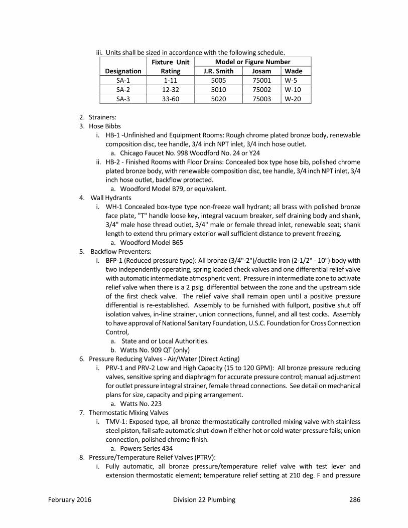
February 2016 Division 22 Plumbing 286
iii. Units shall be sized in accordance with the following schedule.
Designation Fixture Unit
Rating Model or Figure Number
J.R. Smith Josam Wade SA-1 1-11 5005 75001 W-5 SA-2 12-32 5010 75002 W-10 SA-3 33-60 5020 75003 W-20
2. Strainers: 3. Hose Bibbs
i. HB-1 -Unfinished and Equipment Rooms: Rough chrome plated bronze body, renewable composition disc, tee handle, 3/4 inch NPT inlet, 3/4 inch hose outlet.
a. Chicago Faucet No. 998 Woodford No. 24 or Y24 ii. HB-2 - Finished Rooms with Floor Drains: Concealed box type hose bib, polished chrome
plated bronze body, with renewable composition disc, tee handle, 3/4 inch NPT inlet, 3/4 inch hose outlet, backflow protected.
a. Woodford Model B79, or equivalent. 4. Wall Hydrants
i. WH-1 Concealed box-type type non-freeze wall hydrant; all brass with polished bronze face plate, "T" handle loose key, integral vacuum breaker, self draining body and shank, 3/4" male hose thread outlet, 3/4" male or female thread inlet, renewable seat; shank length to extend thru primary exterior wall sufficient distance to prevent freezing.
a. Woodford Model B65 5. Backflow Preventers:
i. BFP-1 (Reduced pressure type): All bronze (3/4"-2")/ductile iron (2-1/2" - 10") body with two independently operating, spring loaded check valves and one differential relief valve with automatic intermediate atmospheric vent. Pressure in intermediate zone to activate relief valve when there is a 2 psig. differential between the zone and the upstream side of the first check valve. The relief valve shall remain open until a positive pressure differential is re-established. Assembly to be furnished with fullport, positive shut off isolation valves, in-line strainer, union connections, funnel, and all test cocks. Assembly to have approval of National Sanitary Foundation, U.S.C. Foundation for Cross Connection Control,
a. State and or Local Authorities. b. Watts No. 909 QT (only)
6. Pressure Reducing Valves - Air/Water (Direct Acting) i. PRV-1 and PRV-2 Low and High Capacity (15 to 120 GPM): All bronze pressure reducing
valves, sensitive spring and diaphragm for accurate pressure control; manual adjustment for outlet pressure integral strainer, female thread connections. See detail on mechanical plans for size, capacity and piping arrangement.
a. Watts No. 223 7. Thermostatic Mixing Valves
i. TMV-1: Exposed type, all bronze thermostatically controlled mixing valve with stainless steel piston, fail safe automatic shut-down if either hot or cold water pressure fails; union connection, polished chrome finish.
a. Powers Series 434 8. Pressure/Temperature Relief Valves (PTRV):
i. Fully automatic, all bronze pressure/temperature relief valve with test lever and extension thermostatic element; temperature relief setting at 210 deg. F and pressure
February 2016 Division 22 Plumbing 287
setting at 150 psig; valve to meet ASME Standards and comply with the latest AGA ratings. Relief opening to be piped to an indirect connection at nearest floor drain.
E. HEATING WATER AND GLYCOL PIPING, ABOVE GROUND 1. Copper Tubing: ASTM B88, Type L, hard drawn.
i. Fittings: ASME or B16.22, solder wrought copper. ii. Joints:
a. 2 inch (75mm) and Under: ASTM B32 solder, grade 95TA or ANSI/AWS A5.8, BcuP-6 silver braze.
b. 2-1/2” or larger steel shall be welded. 2. All Hydronic copper piping shall be silver brazed. Silver brazing material to equal Harris Stay
Silver with minimum 5% silver content or equal. The only exception is when connecting to equipment that could be damaged by excessive heat.
F. HEAT PUMP PIPING, BURIED 1. PIPE AND FITTINGS
i. Hot water heating in building below ground: a. Piping shall be Type "K" soft drawn copper tubing. There shall be no buried
fittings under the building. 2. Single Wall Type.
i. Pipe: a. High Density Polyethylene Pipe manufactured to controlled dimensions,
specifications, and requirements per ASTM D3035. Resins shall be pipe grade resin, possessing ASTM D3350 cell classification No. 345464C. Resin shall be listed in PPI TR4. Pipe shall be virgin resin with an allowance for on-site manufacturer re-processed resin. Recycled resin shall not be permitted.
b. Marking. Each pipe shall be permanently indent marked with the manufacturer’s name, nominal pipe size, pressure rating, relevant ASTM standards, cell classification number, and date of manufacture.
ii. Fittings: a. Molded fittings shall be manufactured to the dimensions, specifications, and
requirements of ASTM D2683 (for socket fusion fittings), ASTM D3261 (for butt/saddle fusion fittings), or ASTM F1055 (for electrofusion fittings). The material used in the manufacture of the fitting shall be the same approved base resin material as the connecting pipe.
b. Marking. Each fitting shall be permanently marked with the manufacturer’s name, nominal pipe size, pressure rating, relevant ASTM standards, and lot number.
iii. Joints. Joints shall be made using heat fusion, flanging, transition fittings, and proof-tested, approved mechanical couplers. Trained and qualified construction crew staff shall make all fusion joints.
G. HEAT PUMP PIPING, ABOVE GROUND 1. PIPE AND FITTINGS
i. Domestic water (hot, circulating hot and cold water) in building above ground: a. 3" and smaller: Piping shall be Type "L" hard drawn copper water tube, per
ASTM B88. Fittings wrought copper, solder joint. There shall be no water lines run in exterior walls.
ii. Heating Water and Chilled Water Piping:

February 2016 Division 22 Plumbing 288
a. 2 Inches and smaller: 1. Type L hard drawn copper, wrought copper fittings. Silver solder with 5%
silver content (Harris StaySilv 5 Silver Brazing Alloy, or equal) for all brazed joints except when connecting to equipment that could be damaged by excessive heat. No heating or chilled piping to be located in exterior walls.
b. 2-1/2 Inches and Larger: 1. Schedule 40, black steel with flanged or welded joints. 2. Fittings: Standard weight, seamless steel, butt weld type. 3. Flanges: 150 lb. forged steel slip-on or welding neck type. 4. Bolting: Regular square head machine bolts with heavy hexagonal nuts.
H. Gaskets: Thickness, material type suitable for fluid to be handled, design temperatures, and pressures 1. 2” and smaller to be Copper Tubing: ASTM B88, Type L, hard drawn.
i. Fittings: ASME B16.18, cast brass or B16.22, solder wrought copper brazed. ii. Joints:
2. 2-1/2” and larger to be steel pipe with welded fittings. I. EQUIPMENT DRAINS AND OVERFLOWS
1. Copper Tubing: ASTM B88, Type L, hard drawn.
i. Fittings: ASME B16.22 solder wrought copper. ii. Joints: Solder, lead free, ASTM B32, Grade 50 TL.
Part 3: Execution 3.01 Preparation
A. Verify all dimensions by field measurements. Verify that all water distribution piping may be installed in accordance with pertinent codes and regulations, the original design, and the referenced standards.
B. Examine rough-in requirements for plumbing fixtures and other equipment having water connections to verify actual locations of piping connections prior to installation.
C. Do not proceed until unsatisfactory conditions have been corrected. D. Ream pipe and tube ends. Remove burrs. Bevel plain and ferrous pipe. If pipe at any point in
the project is found not reamed, contractor may be required to disassemble all piping installed and have a 3rd party (approved by engineer and CITY OF FORT COLLINS) verify reaming is complete. Costs for destructive research, whether more areas are found defective or not, shall be the responsibility of the contractor.
E. Remove scale and dirt on inside and outside before assembly. F. Provide piping connections to equipment with flanges or unions. G. Keep open ends of pipe free from scale and dirt. Protect open ends with temporary plugs or
caps. H. After completion, fill, clean, vent, and chemically treat systems.
3.02 Installation A. PIPING INSTALLATION
1. Route piping in orderly manner, plumb and parallel to building structure, and maintain gradient. 2. Install piping to conserve building space, and not interfere with use of space and other work.

February 2016 Division 22 Plumbing 289
3. Do not install underground piping when bedding is wet or frozen. 4. Group piping whenever practical at common elevations. 5. Install piping to allow for expansion and contraction without stressing pipe, joints, or connected
equipment. 6. Provide clearance for installation of insulation and access to valves and fittings. 7. Provide access where valves and fittings are not exposed. 8. Slope piping and arrange systems to drain at low points. Use eccentric reducers to maintain top
of pipe level, for hydronic systems; bottom of pipe level for steam and refrigeration systems. 9. Where pipe support members are welded to structural building framing, scrape, brush, clean,
and apply one coat of zinc to rich primer to welds. 10. Prepare pipe, fittings, supports, and accessories, for finish painting. 11. Install valves with stems upright or horizontal, not inverted. 12. Install polyethylene tape on buried fittings and joints, extending 4 inches (100 mm) each side of
fitting or joint. Clean area to receive tape with solvent. 13. Underground Steel Pipe.
a. Holiday test 100 % of underground coated steel piping systems with high voltage test device. Ensure zero voids and holidays prior to backfilling. Submit written report.
b. Provide cathodic protection; provide supervision by anode manufacturer’s representative.
c. Provide isolation fittings (dielectric) at building. A. PIPE AND TUBE JOINT CONSTRUCTION B. HOT WATER HEATING SYSTEMS:
1. The hot water heating system shall have manual air vents at all high points and at all points where drops occur in lines. Actual locations of manual air vents shall be marked on As Built Drawings.
C. GENERAL APPLICATION 1. Install union downstream of valves and at equipment or apparatus connections. 2. Install ball or butterfly valves for shut-off and to isolate equipment part of systems. 3. Install plug valve, ball valve, or butterfly valve for balancing/throttling, bypass, or manual flow
control services; however, ball valves shall be specifically shown in manufacturer’s published product data as being suitable for continuous throttling.
4. Provide spring loaded non-slam check valves on discharge of condenser water pumps. 5. Use butterfly valve operators as follows: 6. All sizes to have gear operators. 7. Provide ¾ inch (20 mm) ball drain valves at main shut-off valves, low points of piping, bases of
vertical risers, and at equipment. Pipe to nearest drain. D. VALVE APPLICATIONS
1. General Duty Valve Applications: i. Shut-off duty: Use ball valves only. ii. Throttling duty: Use globe and ball valves.
E. INSTALLATION OF VALVES 1. Sectional Valves: Install sectional valves on each branch and riser, close to main, where branch
or riser serves 2 or more plumbing fixtures or equipment connections. For sectional valves 2"

February 2016 Division 22 Plumbing 290
and smaller, use ball valves; for sectional valves 2- 1/2" and larger, use ball valves only. 2. Shutoff Valves: Install shutoff valves on inlet of each plumbing equipment item, and on inlet of
each plumbing fixture. For shutoff valves 2" and smaller, use ball valves; for shutoff valves 2- 1/2" and larger, use ball valves only.
3. Drain Valves: Install drain valves on each plumbing equipment item, located to completely drain equipment for service or repair. Install drain valves at the base of each riser, at low points of horizontal runs, and elsewhere as required to completely drain distribution piping system. For drain valves 2" and smaller, use ball valves; for drain valves 2-1/2" and larger, use ball valves only. All drains that are not piped to a drain are to have a ¾” hose connection with chain and cap. (Apollo 78-200-01).
4. Check Valves: Install swing check valves on discharge side of each pump. 5. Balance Cocks: Install in each hot water recirculating loop, discharge side of each pump.
Balance cocks are not to be used as isolation valves. 6. Hose Bibbs: Install on exposed piping, with vacuum breaker. 7. Wall Hydrants: Install with vacuum breaker. All hose bibs are to have an isolation valve
installed for maintenance and repairs. F. INSTALLATION OF PIPING SPECIALTIES
1. Install backflow preventers at each connection to mechanical equipment and systems, and in compliance with the plumbing code and authority having jurisdiction. Locate in same room as equipment being connected. Pipe relief outlet thru air gap and without valves, full-size to nearest floor drain. Provide floor drain at each backflow preventer, size as required to meet backflow. (i.e. – 1” device requires 2” drain; 2” device requires 4” drain.
2. Install pressure regulating valves with inlet and outlet shutoff valves, and balance cock bypass. Install pressure gauge on valve outlet. Provide unions on both sides of PRV.
G. EQUIPMENT CONNECTIONS 1. Piping Runouts to Fixtures: Provide hot and cold water piping runouts to fixtures AS CODE
REQUIRES. 2. Mechanical Equipment Connections: Connect hot and cold water piping system to mechanical
equipment. Provide shutoff valve and union for each connection, provide drain valve on drain connection. For connections 2-1/2" and larger, use flanges instead of unions.
H. FIELD QUALITY CONTROL 1. Inspections: Inspect water distribution piping as follows:
i. Do not enclose, cover, or put into operation water distribution piping system until it has been inspected and approved by the authority having jurisdiction.
ii. During the progress of the installation, notify the plumbing official having jurisdiction, at least 48 hours prior to the time such inspection must be made. Perform tests specified below in the presence of the plumbing official.
a. Rough-in Inspection: Arrange for inspection of the piping system before concealed or closed-in after system is roughed-in, and prior to setting fixtures.
b. Final Inspection: Arrange for a final inspection by the plumbing official to observe the tests specified below and to insure compliance with the requirements of the plumbing code.
iii. Reinspections: Whenever the plumbing official finds that the piping system will not pass the test or inspection, make the required corrections and arrange for reinspection by the plumbing official.
iv. Reports: Prepare inspection reports, signed by the plumbing official. 2. Test water distribution piping.
I. Hose Bibbs and Wall Hydrants:
February 2016 Division 22 Plumbing 291
1. Locations: i. Each mechanical room where there is cold potable water service. ii. Inside Kitchen iii. Gang toilet rooms. (Key closed wall hydrant – box type.) iv. Mechanical penthouses, if heated. v. Boiler room. vi. Wall hydrant every 200 feet of exterior perimeter. vii. Wall hydrant outside at the kitchen service entrance. viii. Custodial closets.
2. Provide freeze-proof outside wall hydrants with inside ball and drain valves in heated areas for winter shut off.
J. Minimum Locations of Floor Drains: 1. Mechanical rooms. 2. Kitchen. 3. Every toilet room. 4. Mechanical penthouses. 5. Emergency drench showers. 6. Custodial closets. 7. All backflow preventer locations.
3.03 Cleaning and Protection A. ADJUSTING AND CLEANING
1. Flushing and cleaning of water distribution piping shall be witnessed by a City of Fort Collins Representative. Provide minimum of 24 hours notice prior to performing work.
2. Clean and disinfect water distribution piping as follows: i. Purge all new water distribution piping systems and parts of existing systems, which have
been altered, extended, or repaired prior to use. ii. Use the purging and disinfecting procedure prescribed by the authority having
jurisdiction, or in case a method is not prescribed by that authority, the procedure described in either AWWA C651, or AWWA C652, or as described below:
a. Flush the piping system with clean, potable water until dirty water does not appear at the points of outlet.
b. Fill the system or part thereof, with a water/chlorine solution containing at least 50 parts per million of chlorine. Isolate (valve off) the system, or part thereof, and allow to stand for 24 hours.
c. Drain the system, or part thereof, of the previous solution, and refill with a water/chlorine solution containing at least 200 parts per million of chlorine and isolate and allow to stand for 3 hours.
d. Following the allowed standing time, flush the system with clean potable water until chlorine does not remain in the water coming for the system.
e. Submit water samples in sterile bottles to the authority having jurisdiction. Repeat the procedure if the biological examination made by the authority shows evidence of contamination.
3. Prepare reports for all purging and disinfecting activities. 4. Domestic Water Systems:
i. General: All new potable water systems shall be cleaned as herein specified prior to testing or application of insulation. Testing must be witnessed by District and State Department of Health personnel and report filed with the District to receive final payment.
February 2016 Division 22 Plumbing 292
ii. Notification: Notify State Department of Health in writing, 48 hours in advance of the beginning of the cleaning process.
iii. Witness: The cleaning process will not be deemed acceptable unless witnessed and approved by the State Department of Health's representative.
iv. Procedure: Comply with City of Fort Collins standards or Colorado State Department of Health requirements, whichever is more stringent.
v. Report: The report shall contain the following and be submitted to the District's Project Manager within 24 hours of the cleaning:
a. Date, time, and place of cleaning. b. Duration. c. Person responsible. d. Solutions concentration and temperature. e. Signature of State Department of Health representative. f. Results.
vi. The report and its timely submission shall be required for final payment. 5. Heating Water System:
i. Notification: Notify District's Project Manager 24 hours in advance of the beginning of the cleaning process. The cleaning process will not be deemed acceptable unless witnessed and approved by the District's representative. This shall be a requirement for final payment.
ii. Procedure: Flush all systems with clean city water until the discharge is clear. Clean or replace the baskets of all strainers after cleaning.
iii. Drain system, and fill system with clean water, mixed with propylene glycol with inhibitors to 30% by volume. If there is excess propylene glycol, turn remaining over to Owner.
END OF SECTION 22 11 13
SECTION 22 11 23 – FACILITY NATURAL GAS PIPING Part 1: General 1.01 Summary
A. This section includes distribution piping systems for natural gas and manufactured gas within the building and extending from the point of delivery to the connections with gas utilization devices. Piping materials and equipment specified in this section include: 1. Pipes, fittings, and specialties. 2. Special duty valves.
B. This section does not apply to LP-gas piping; industrial gas applications using such gases as acetylene and acetylenic compounds, hydrogen, ammonia, carbon monoxide, oxygen and nitrogen; gas piping, meters, gas pressure regulators and other appurtenances used by the serving gas supplier in distribution of gas.
C. Gas pressures for systems specified in this section are limited to 5 psig. D. Products installed but not furnished under this section include gas meters which will be provided
by the utility company, to the site, ready for installation. 1.02 Related Sections

February 2016 Division 22 Plumbing 293
1.03 Definitions 1.04 Submittals Required.
A. Product data B. Shop drawings C. Record Drawings: D. Maintenance data E. Welders' qualification F. Test reports.
1.05 Quality Assurance A. Manufacturer's Qualifications: not less than 5 years. B. Installer Qualifications: minimum of 5 previous projects similar in size and scope to this project
1.06 Scheduling 1.07 Delivery, Storage, and Handling 1.08 Regulatory Requirements
A. EXTRA MATERIALS 1. Valve Wrenches: Furnish to Owner, with receipt, 2 valve wrenches for each type of gas valve
installed, requiring same. Part 2: Products 2.01 Manufacturers
A. Manufacturer: Subject to compliance with requirements, provide products by one of the following: 1. Gas Cocks:
i. Jenkins Bros. ii. Lunkenheimer Co. iii. Stockham.
2.02 Products A. PIPE, TUBING AND JOINTING MATERIALS
1. Natural gas in building above ground: i. Piping shall be black steel, Schedule 40, plain ends for welding for 2-1/2" and above.
Fittings welded, standard weight. Joints welded as recommended by AWS or NCPWB. ii. For 2" and smaller, piping shall be black steel, Schedule 40, screw ends. Fittings black
malleable iron screwed, standard weight 150 lb. banded. Minimize gas piping inside the building by running pipe on the roof wherever possible. Support pipe on roof with Bizon Pipe Jacks, or as per manufacturer's recommendations for single ply membrane roofs. Entire pipe shall be primed and painted by the painting contractor to prevent rusting. Support pipe at 10 ft. intervals for 1-1/4" pipe and larger, and at 8 ft. intervals for 3/4" or 1" pipe. Pipe installed in a return air plenum must be welded. No screwed fittings.
2. Natural and LP gas buried in ground: i. Polyethylene pipe (PLEXCO Yellow pipe PE 2406 or approved equal) with iron pipe
transition risers. Install tracer wire in trench above poly pipe before backfilling. -or- ii. Piping shall be black steel, Schedule 40, plain ends for welding. Fittings welded,
standard weight. Joints welded as recommended by AWS or NCPWB. Tape all joints and mill wrap all pipe and fittings.
B. NATURAL GAS PIPING SPECIALTIES 1. Protective Coating: Provide factory applied polyethylene tape, having the following properties:
i. Overall thickness; 20 mils. ii. Synthetic adhesive.
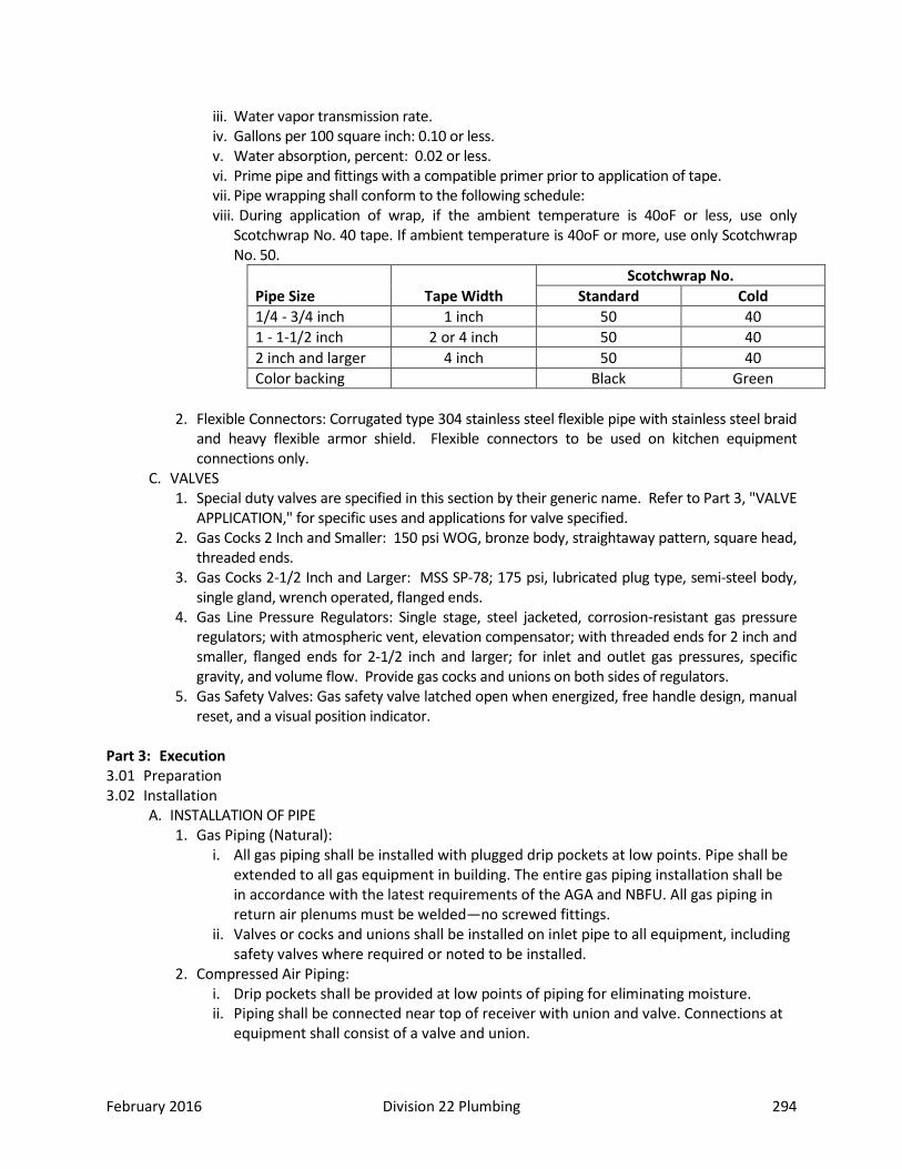
February 2016 Division 22 Plumbing 294
iii. Water vapor transmission rate. iv. Gallons per 100 square inch: 0.10 or less. v. Water absorption, percent: 0.02 or less. vi. Prime pipe and fittings with a compatible primer prior to application of tape. vii. Pipe wrapping shall conform to the following schedule: viii. During application of wrap, if the ambient temperature is 40oF or less, use only
Scotchwrap No. 40 tape. If ambient temperature is 40oF or more, use only Scotchwrap No. 50.
Pipe Size Tape Width Scotchwrap No.
Standard Cold 1/4 - 3/4 inch 1 inch 50 40 1 - 1-1/2 inch 2 or 4 inch 50 40 2 inch and larger 4 inch 50 40 Color backing Black Green
2. Flexible Connectors: Corrugated type 304 stainless steel flexible pipe with stainless steel braid
and heavy flexible armor shield. Flexible connectors to be used on kitchen equipment connections only.
C. VALVES 1. Special duty valves are specified in this section by their generic name. Refer to Part 3, "VALVE
APPLICATION," for specific uses and applications for valve specified. 2. Gas Cocks 2 Inch and Smaller: 150 psi WOG, bronze body, straightaway pattern, square head,
threaded ends. 3. Gas Cocks 2-1/2 Inch and Larger: MSS SP-78; 175 psi, lubricated plug type, semi-steel body,
single gland, wrench operated, flanged ends. 4. Gas Line Pressure Regulators: Single stage, steel jacketed, corrosion-resistant gas pressure
regulators; with atmospheric vent, elevation compensator; with threaded ends for 2 inch and smaller, flanged ends for 2-1/2 inch and larger; for inlet and outlet gas pressures, specific gravity, and volume flow. Provide gas cocks and unions on both sides of regulators.
5. Gas Safety Valves: Gas safety valve latched open when energized, free handle design, manual reset, and a visual position indicator.
Part 3: Execution 3.01 Preparation 3.02 Installation
A. INSTALLATION OF PIPE 1. Gas Piping (Natural):
i. All gas piping shall be installed with plugged drip pockets at low points. Pipe shall be extended to all gas equipment in building. The entire gas piping installation shall be in accordance with the latest requirements of the AGA and NBFU. All gas piping in return air plenums must be welded—no screwed fittings.
ii. Valves or cocks and unions shall be installed on inlet pipe to all equipment, including safety valves where required or noted to be installed.
2. Compressed Air Piping: i. Drip pockets shall be provided at low points of piping for eliminating moisture. ii. Piping shall be connected near top of receiver with union and valve. Connections at
equipment shall consist of a valve and union.

February 2016 Division 22 Plumbing 295
iii. Install pipe tee at compressor, so that quick coupler may be added later to service condenser coil on air dryer.
3. Concealed Locations: Except as specified below, install concealed gas piping in an air-tight conduit constructed of Schedule 40, seamless black steel with welded joints. Vent conduit to the outside and terminate with a screened vent cap.
i. Above-Ceiling Locations: Gas piping may be installed in accessible above-ceiling spaces (subject to the approval of the authority having jurisdiction), whether or not such spaces are used as a plenum. Valves shall not be located in such spaces.
ii. Piping In Partitions: Concealed piping shall not be located in solid partitions. Tubing shall not be run inside hollow walls or partitions unless protected against physical damage. This does not apply to tubing passing through walls or partitions.
iii. Prohibited Locations: Do not install gas piping in or through a circulating air duct, clothes chute, chimney or gas vent, ventilating duct, dumb waiter or elevator shaft. This does not apply to accessible above-ceiling space specified above.
4. Drips and Sediment Traps: Install a drip leg at points where condensate may collect, at the outlet of the gas meter, and in a location readily accessible to permit cleaning and emptying. Do not install drips where condensate is likely to freeze.
i. Construct drips and sediment traps using a tee fitting with the bottom outlet plugged or capped. Use a minimum of 3 pipe diameters in length for the drip leg. Use same size pipe for drip leg as the connected pipe.
5. Use fittings for all changes in direction and all branch connections. 6. Install gas piping at a uniform grade upward to risers, and from the risers to the meter, or
service regulator when meter is not provided, or the equipment. 7. Connect branch outlet pipes from the top of horizontal lines, not from the bottom or sides.
B. NATURAL GAS PIPING SPECIALTIES 1. Protective Coating:
i. Provide protective coating on piping and fittings that will be in contact with material or atmosphere exerting a corrosive action, or piping buried in floors. Protective coating shall be applied at the factory.
2. Flexible Connectors: i. Provide flexible braided stainless steel connectors with full size quick coupler for all
kitchen gas appliance equipment only. ii. Connectors shall be of lengths required to displace equipment for complete cleaning
under and around gas appliance. Equip flexible connectors with quick couplers and tether.
C. VALVE APPLICATIONS 1. Shut-off duty: Use gas cocks.
D. VALVE INSTALLATIONS 1. Install valves in accessible locations, protected from physical damage. Tag valves with a metal
tag attached with a metal chain indicating the piping systems supplied. 2. Install a gas cock both sides of each gas pressure regulator. Where two gas pressure regulators
are installed in series in a single gas line, a manual valve is not required at the second regulator. 3. Install pressure relief devices so they can be readily operated to determine if the valve is free;
so they can be tested to determine the pressure at which they will operate; and examined for leakage when in the closed position. Pipe atmospheric vent to outdoors.
4. Valves shall be installed with unions or other means to facilitate removal or repair without disassembly of connecting piping.
5. Gas Safety Valves:
February 2016 Division 22 Plumbing 296
i. Install gas safety valves in wall boxes. ii. Coordinate electrical requirements with contractor. Provide neoprene grommets for all
piping and electrical conduit entering and existing cabinets. E. TERMINAL EQUIPMENT CONNECTIONS
1. Install gas cock upstream and within 6 feet of gas appliance. Install a union or flanged connection downstream from the gas cock to permit removal of controls.
2. Sediment Traps: Install a tee fitting with the bottom outlet plugged or capped as close to the inlet of the gas appliance as practical. Drip leg shall be a minimum of 3 pipe diameters in length. Provide valve above drip leg so gas service does not have to be shut down. The valve can be used to isolate the equipment being served.
3. Flexible Hose Gas Connectors: For use connecting to vibrating equipment; corrugated Type 304 stainless steel flexible pipe with stainless steel braid.
F. ELECTRICAL BONDING AND GROUNDING G. SPARE PARTS
1. Valve Wrenches: Furnish to Owner, with receipt, 2 valve wrenches for each type of gas valve installed, requiring same.
3.03 Cleaning and Protection
END OF SECTION 22 11 23
SECTION 22 13 16 – SANITARY WASTE AND VENT PIPING Part 1: General 1.01 Summary
A. This section specifies building sanitary drainage and vent piping systems, including drains and drainage specialties.
1.02 Related Sections 1.03 Definitions 1.04 Submittals Required
A. Product Data: B. Shop Drawings: C. Record Drawings: D. Maintenance Data:
1.05 Quality Assurance A. Regulatory Requirements: Comply with the provisions of the following:
1. Plumbing Code Compliance: Comply with applicable portions of International Plumbing Code. 2. ANSI Compliance: Comply with applicable ANSI standards pertaining to materials, products,
and installation of soil and waste systems. 3. ASSE Compliance: Comply with applicable ASSE standards pertaining to materials, products,
and installation of soil and waste systems. 4. PDI Compliance: Comply with applicable PDI standards pertaining to products and installation
of soil and waste systems. 5. PVC Pipe: Only Contractor's personnel which have received training in the installation of this
material and meet the manufacturer's qualifications shall do the assembly of such material. 1.06 Scheduling 1.07 Delivery, Storage, and Handling 1.08 Regulatory Requirements

February 2016 Division 22 Plumbing 297
Part 2: Products 2.01 Manufacturers
A. Manufacturer: Subject to compliance with requirements, provide drainage and vent systems from one of the following: 1. Drainage Piping Specialties, including drains and cleanouts:
i. Josam Mfg. Co. ii. Smith (Jay R) Mfg. Co. iii. Zurn Industries Inc; Hydromechanics Div. iv. Wade
2.02 Products A. DRAINAGE PIPING SPECIALTIES
1. Vent Flashing Sleeves: Cast-iron caulking type roof coupling for cast-iron stacks, cast-iron threaded type roof coupling for steel stacks, and cast-bronze stack flashing sleeve for copper tubing.
2. Vandal – Proof Vent Caps: Cast Iron dome secured with Allen Key set screws. J.R. Smith Model 1748 or equivalent. Vent cap must be compatible with type of vent flashing installed.
B. CLEANOUTS 1. Floor Cleanout: Round, cast iron body with recessed bronze closure plug; scoriated polished
bronze frame and cover plate. No floor cleanouts in carpeted floors. 2. Wall Cleanout: Cleanout tee with raised head brass plug tapped for 1/4-20 thread; flat style
chrome plated wall cover plate with holes for 1/4" bolt; 1/4-20 threaded bolt with chrome plated flat head.
3. Surface Cleanout: Cast iron body ferrule with raised head brass plug. Medium duty cast iron manhole cover and ring 12" diameter to be set in a minimum 24” X 24” X 4” thick concrete pad, Neenah No. R-1791-A.
4. Line Cleanout: Cast iron tapped cleanout ferrule with raised head brass plug. C. FLOOR DRAINS
1. Floor drain. i. FD-1 Toilet Rooms and Finished Areas
a. Round cast iron body with flashing collar and cast iron ring, 6 inch round nickel bronze adjustable strainer head with secured square hole grate, bottom waste outlet. Jay R. Smith Fig. 2005-A
ii. FD-2 Boiler and Mechanical Rooms a. Round cast iron, medium duty, shallow body drain with flashing collar and cast iron
ring, 8" round tractor type non-tilt slotted grate, bottom waste outlet. Jay R. Smith Fig. 2210
2. All floor drains will require a “trickler” per code. D. FLOOR SINKS
1. Floor drain. i. FS-1 Indirect Waste Drain - Kitchen Sinks
a. Square, cast iron, porcelain enameled interior, sump body drain 8" deep x 12" square with flashing collar and cast iron ring, 12" square nickel bronze removable half top grate with cast aluminum dome bottom strainer, bottom waste outlet.
b. Jay R. Smith Fig. 3120 ii. FS-2 Indirect Waste Drain - Kitchen Equipment
a. Square, cast iron, porcelain enameled interior, sump body drain 6" deep x 8" square with flashing collar and cast iron ring, 8" square nickel bronze removable half top

February 2016 Division 22 Plumbing 298
grate, cast aluminum dome button strainer, bottom waste outlet. b. Jay R. Smith 3100
Part 3: Execution 3.01 Preparation 3.02 Installation
A. INSTALLATION 1. The installation of off-set closet flanges is prohibited. 2. All floor drains are to be provided with P-trap the same size as the floor drain. All floor drains
are to have trap primers. 3. Provide flashing membrane for all floor drains in structure above slab on grade level. 4. Lubricate cleanout plugs with mixture of graphite and linseed oil. Prior to building turnover
remove cleanout plugs, re-lubricate and reinstall using only enough force to ensure permanent leak proof joint.
5. Provide flashing for all floor drains, floor cleanouts and shower drains above grade. Make watertight with Chloraloy 240 under slab moisture vapor barrier as manufactured by the Nobel Co. of Grand Haven, Michigan. Flashing shall extend at least 24" from drain rim into floor membrane or on structural floor. Fasten flashing to drain clamp device and make watertight, durable joint. Provide flashing collar extension with all drains and cleanouts installed above grade.
6. Provide full-size clean-outs in all restroom groups. Do not locate floor clean-outs in carpeted areas.
7. Cross-type drainage fittings shall not be installed in waste piping. 8. All bathrooms to have floor drains.
B. HANGERS AND SUPPORTS: See specific section. C. INSTALLATION OF PIPING SPECIALTIES
1. Install backwater valves in sanitary building drain piping. For interior installation, provide minimum 13" dia. cleanout cover flush to floor centered over backwater valve cover and of adequate size to remove valve cover for service.
2. Above Ground Cleanouts: i. As required by plumbing code; ii. At each change in direction of piping greater than 45 degrees below slab; iii. At minimum intervals of 50'; iv. At base of each vertical soil or waste stack at 12" AFF; v. At sinks and urinals on grade; vi. At each upper terminal; vii. At egress of building (surface cleanout). viii. At each water closet or toilet group.
3. Cleanouts Covers: Install floor and wall cleanout covers for concealed piping, and in accessible locations.
4. Flashing Flanges: Install flashing flange and clamping device with each stack and cleanout passing through waterproof membranes.
5. Vent Flashing Sleeves: Install on stacks passing through roof, secure over stack flashing in accordance with manufacturer's instructions.
D. PIPE AND TUBE JOINT CONSTRUCTION 1. Install pipes and pipe joints in accordance with appropriate sections.
E. INSTALLATION OF FLOOR DRAINS 1. Install floor drains at low points of surface areas to be drained. Set tops of drains flush with

February 2016 Division 22 Plumbing 299
finished floor. 2. Trap all drains connected to the sanitary sewer with minimum trap size that of drain connected. 3. Install drain flashing collar or flange so that no leakage occurs between drain and adjoining
flooring. Maintain integrity of waterproof membranes, where penetrated. 4. Position drains so that they are accessible and easy to maintain. 5. Provide trap primers for all drains.
F. WASTE, VENT, AND STORM PIPING: 1. All waste, vent, and storm drain piping shall be properly pitched at 1/4 inch to the foot (or
2%) minimum for 4" and smaller pipe and 1/8 inch (or 1%) minimum for 5 inch and larger. Piping shall be properly supported so that it will not sag and form pockets. Exceptions must be approved in writing by the City of Fort Collins, and approved by the Administrative Authority.
2. The manufacturer's recommendations shall be carefully followed when installing pipe using neoprene gasket joints.
3. Locate vertical hubs of underground piping below partition walls for concealment. In locations where hubs will project beyond finish partition wall, set hubs 1" below finished floor.
4. All waste, vent, and storm pipe underground outside of building shall be buried a minimum of 3'-6" deep. Install tracer wire on all exterior utilities. Terminate in an approved termination box.
5. Where waste lines from fixtures are to be acid resistant, the vents shall also be acid resistant through roof.
G. CLEANOUTS: 1. Full size brass cleanout plugs. 2. Wall cleanouts located 4" to 6" above floor with chrome-plated covers. Bottom of cleanout
cover shall be 1" minimum above top of baseboard. 3. Provide at 50 feet maximum intervals for all pipe sizes and wherever pipes change direction 45
degrees or more. 4. Scored brass cover for floor cleanout installed flush with the floor. 5. Outside of building starting 10 feet from perimeter wall:
i. Locate every 100 feet. ii. Heavy cast iron tractor cover set in 2' x 2' x 6" concrete block. iii. 4" size acceptable in pipes larger than 4".
6. Submit proposed locations of cover plates to CITY OF FORT COLLINS. 7. Do not install floor cleanouts in carpeted areas. 8. If a cleanout must be installed in a carpeted area, use a wall cleanout.
H. SERVICE CONNECTIONS 1. Provide new sanitary and storm sewer services. Before commencing work check invert
elevations required for sewer connections, confirm inverts and ensure that these can be properly connected with slope for drainage and cover to avoid freezing.
I. CONNECTIONS 1. Piping Runouts to Fixtures: Provide drainage and vent piping runouts to plumbing fixtures and
drains, with approved trap; but in no case smaller than required by the plumbing code. 2. Locate piping runouts as close as possible to bottom of floor slab supporting fixtures or drains.
J. FIELD QUALITY CONTROL 1. Inspections:
i. During the progress of the installation, notify the plumbing official having jurisdiction, at least 48 hours prior to the time such inspection must be made.
February 2016 Division 22 Plumbing 300
a. Rough-in Inspection: Arrange for inspection of the piping system before concealed or closed-in after system is roughed-in, and prior to setting fixtures.
b. Final Inspection: Arrange for a final inspection to observe the tests specified and to insure compliance with the requirements of the plumbing code.
ii. Reinspections: Whenever the piping system fails to pass the test or inspection, make the required corrections, and arrange for reinspection.
iii. Reports: Prepare inspection reports, signed by the plumbing official. 2. Post-Installation Inspection: The installing contractor shall perform a visual inspection of all
below-grade building drains using appropriate methods. Owner to be notified at time of inspection and have option to be present.
3.03 Cleaning and Protection
END OF SECTION 22 13 16
SECTION 22 13 23 – SANITARY WASTE INTERCEPTORS Part 1: General 1.01 Summary 1.02 Related Sections 1.03 Definitions 1.04 Submittals Required
A. Product Data: B. Shop Drawings: C. Record Drawings: D. Maintenance Data:
1.05 Quality Assurance A. Manufacturer's Qualifications: not less than 5 years. B. Codes and Standards:
1. PDI Compliance: Test and rate grease interceptors in accordance with PDI Standard G101, "Testing and Rating Procedure for Grease Interceptors."
1.06 Scheduling 1.07 Delivery, Storage, and Handling 1.08 Regulatory Requirements Part 2: Products 2.01 Manufacturers
A. Manufacturers: Subject to compliance with requirements, provide products by one of the following: 1. Grease Interceptors:
i. Copeland Enterprises, Inc. ii. Front Range Pre-Cast Concrete iii. Colorado Precast
2.02 Products A. GREASE INTERCEPTORS
1. Unit shall be pre-cast concrete, as manufactured by Copeland Enterprises, Inc., 904 S. Lipan,
February 2016 Division 22 Plumbing 301
Denver, CO 80223, Phone No. 936-4817, Front Range Precast Concrete, Colorado Precast, or approved equal.
i. No multi-piece grease traps shall be accepted. Grease traps must be one-piece vault with lid as per the Colorado Precast Concrete Specifications.
2. Variations: Provide the following construction feature variations: i. Lift out sediment bucket. ii. Enzyme opening.
3. Unit shall be complete with internal baffle for secondary compartment of one-third the total capacity, and concrete cover, with manholes.
4. Unit shall be reinforced with 6x6, 10/10 mesh and three No. 4 horizontal re-bar in walls. Cover reinforced with No. 5 re-bar at 8" o.c. and No. 5 around manholes.
5. Install approved sill cock within 25' of all grease traps. 6. Manholes to Grease Trap:
i. Manholes shall be constructed of pre-cast concrete rings manufactured to ASTM specifications, and laid up in cement mortar. Construct to conform with City, and State Standards with the top to meet a 24" diameter cast iron manhole ring and cover. Cover must be flush with finish grade. Provide heavy duty type ring and cover, gas-tight, Model 1073.
Part 3: Execution 3.01 Preparation 3.02 Installation 3.03 Cleaning and Protection
END OF SECTION 22 13 23
SECTION 22 14 13 – FACILITY STORM DRAINAGE PIPING Part 1: General 1.01 Summary
A. This section specifies storm drainage and vent piping systems, including drains and drainage specialties.
1.02 Related Sections 1.03 Definitions 1.04 Submittals Required
A. Product Data: B. Shop Drawings: C. Record Drawings: D. Maintenance Data:
1.05 Quality Assurance 1.06 Scheduling 1.07 Delivery, Storage, and Handling 1.08 Regulatory Requirements
February 2016 Division 22 Plumbing 302
Part 2: Products 2.01 Manufacturers
A. Manufacturer: Subject to compliance with requirements, provide drainage and vent systems from one of the following: 1. Drainage Piping Specialties, including drains and cleanouts:
i. Josam Mfg. Co. ii. Smith (Jay R) Mfg. Co. iii. Zurn Industries Inc; Hydromechanics Div. iv. Wade
2.02 Products A. PIPE AND FITTING
1. Building storm and sanitary sewer below grade: Cast iron bell & spigot with resilient gasket joints. Schedule 40 solid core PVC pipe and fittings. Purple Primer must be used. Foam core pipe will not be accepted. Cross Fitting will not be accepted.
2. Sanitary, storm and roof drains above grade: Cast iron no-hub, bell & spigot, or copper type DWV. No drain shall be less than 2" nor any drain less than 3" extended more than 20'. Cross fittings are not to be used.
B. STORM DRAINAGE, VENT AND SUBSURFACE DRAINAGE PIPE AND FITTINGS C. DRAINAGE PIPING SPECIALTIES: See Section 22 13 16. D. ROOF DRAINS
1. Roof drain. i. RD-1
a. Cast iron body with sump, removable cast iron vandal-proof dome strainer, cast iron flashing flange and cast iron ring with integral gravel stop, underdeck clamp. Jay R. Smith Fig. 1010
ii. OFD-1 Overflow Drain a. Cast iron body with sump, removable cast iron vandal-proof dome strainer, cast iron
flashing flange and cast iron clamp with integral gravel stop, cast iron underdeck clamp, 3-1/2" high water dam standpipe under dome strainer; where standpipe is set down in sump drill four 1/4" dia. holes, spaced evenly, at base of standpipe for sump drainage.
b. Jay R. Smith Fig. 1070 Part 3: Execution 3.01 Preparation 3.02 Installation
A. INSTALLATION 1. Install overflow roof drains with the inlet flow line located a maximum 2" above the lowest
point of roof. B. PIPE AND TUBE JOINT CONSTRUCTION
1. Install pipes and pipe joints in accordance with appropriate sections. C. INSTALLATION OF ROOF DRAINS
1. Install roof drains at low points of roof areas, in accordance with the roof membrane manufacturer's installation instructions.
2. Install drain flashing collar or flange so that no leakage occurs between roof drain and adjoining roofing. Maintain integrity of waterproof membranes, where penetrated.
3. Position roof drains so that they are accessible and easy to maintain. D. Building Sanitary and Storm Sewer:

February 2016 Division 22 Plumbing 303
1. Locate sewer lines not closer than ten feet horizontally from potable water lines except that if the top level of the sewer is three feet or more below the bottom level of the water line, the horizontal distance between the lines may be reduced to six feet. Provide tracer wire on all exterior utilities, terminated tracer wire in an approved termination box.
2. Where sewer lines cross potable water lines the distance between shall not be less than three feet and the sewer line constructed of standard weight cast iron or Class 50 ductile iron.
3. When encountering unstable soil or when the sewer excavation is through solid shale, slate, sandstone or similar hard material, bed the pipe in 3/4" to 1-1/2" crushed rock or gravel 6" all around the pipe.
E. Roof Drains: 1. Locate at the midspans of the roof steel. 2. Provide flexible connections to risers. 3. Drain to storm sewer or on-site above grade drainage. 4. Where internal overflow drains are required. do not connect to the roof drain piping. Extend
separate lines to the storm drain outside the building. 5. Discharge roof drains into public storm sewers and not over sidewalks or at the tops of
embankments, do not locate at exterior door locations. Locate effluent to preclude soil erosion.
3.03 Cleaning and Protection
END OF SECTION 22 14 13
SECTION 22 16 00 – KITCHEN PIPING Part 1: General 1.01 Summary
A. This section specifies kitchen piping systems. 1.02 Related Sections 1.03 Definitions 1.04 Submittals Required
A. Product Data: B. Shop Drawings: C. Record Drawings: D. Maintenance Data:
1.05 Quality Assurance 1.06 Scheduling 1.07 Delivery, Storage, and Handling 1.08 Regulatory Requirements Part 2: Products 2.01 Manufacturers 2.02 Products
A. PIPE AND FITTING 1. Exposed connections to equipment located in areas scheduled to have carpet or resilient
floor coverings, as in a kitchen.
February 2016 Division 22 Plumbing 304
i. Red brass, standard weight screwed ends, full iron pipe size chrome plated. Fittings brass standard weight, screwed, chrome plated.
B. NO KITCHEN WATER LINES ARE TO BE LOCATED IN EXTERIOR WALLS. Pipes can be mounted to interior of walls (under counters) if they are insulated and have washable surface casing.
C. Kitchen Hose bibs/hose connections must have appropriate backflow prevention devices. All outdoor hose-bibs are to be “Woodford” key-type with vandal-proof cover and have an access panel for isolation valves. Kitchen should have a Hose-bib outside of kitchen within 30 feet of grease trap.
D. Kitchen Water Supply is to be 140 Degrees F., with the exception of hand wash sinks. (Check Larimer County health regulations on hand wash sink temps.)
E. Kitchen Sanitary and grease cleanouts are to be installed in the floor (when not in carpeted areas) and made accessible. (Not behind disposal or dish machine, for example), if necessary cleanouts can be in exterior walls with a cover-plate.
F. Kitchen Shut-off Valves are to be easily accessible either behind kitchen equipment or in ceiling or access panels. Plumbing is to be done so that valves are easily reached inside access panels. This applies to kitchen equipment and HVAC valves.
Part 3: Execution 3.01 Preparation 3.02 Installation 3.03 Cleaning and Protection
END OF SECTION 22 16 00
SECTION 22 30 00 – PLUMBING EQUIPMENT Part 1: General 1.01 Summary
A. SCOPE OF THE WORK i. Sanitary Drainage System. ii. Storm Drainage System. iii. Domestic Water System. iv. Plumbing Fixtures. v. Compressed Air System. vi. Natural Gas System.
B. CONNECTIONS TO MISCELLANEOUS EQUIPMENT C. SANITARY AND STORM SEWER SERVICE
1. Provide minimum 3'6" cover over sewer line(s) outside of building. Provide main cleanout where sewer(s) leaves building. All exterior utilities are to have tracer wire installed. Terminate in an approved termination box.
D. NATURAL GAS SERVICE 1. All underground gas service shall be approved piping; i.e., (P.E.) by gas with tracer wire.
E. WATER SERVICE 1. Job specific. All exterior utilities are to have tracer wire. Terminate in an approved
termination box.
February 2016 Division 22 Plumbing 305
1.02 Related Sections 1.03 Definitions 1.04 Submittals Required 1.05 Quality Assurance 1.06 Scheduling 1.07 Delivery, Storage, and Handling 1.08 Regulatory Requirements Part 2: Products 2.01 Manufacturers 2.02 Products
A. CLEANOUTS* 1. Provide cleanouts as manufactured by Josam, Jay R. Smith, Wade, or Zurn. Cleanouts shall
be full line size through 4" pipe. 2. Cleanout covers shall be "brass," square raised or recessed caps. 3. Inside caulk or spigot connections, bronze cleanout plug, straight threaded with tapered
shoulder and caulked lead seat. Plugs shall be removed, doped, and reinstalled just tight enough to prevent leakage.
4. Screwed pipe cleanouts-bronze pipe threaded plug with four raised square lugs or counter sunk plug.
5. Floor Cleanouts (FCO): Frame and cover threaded for 1-1/2" vertical adjustment, threads protected with shield to be removed when concrete is set. Covers: Nickel bronze round frame and cover, deep flange tractor type. Extra heavy type in heavy traffic areas, and with carpet retainer top for carpeted floors. (Cleanouts will not be located in carpeted areas.)
6. Wall Cleanouts (WCO): Square nickel bronze frame and cover with minimum opening of 6" x 6".
7. Grade Cleanouts (GCO): Cast iron cleanout with round, heavy-duty scoriated, non-tilt cast iron top, adjustable to finished grade level. Set GCO in 2' x 2' x 4" deep concrete pad, minimum.
8. Cleanouts: Located at changes in direction of pipe run and shall consist of 'Y' fittings and eighth bends. Cleanouts shall be provided at the base of all vertical stacks with the cleanout plug located approximately 12 inches above the floor and extended to wall access cover. Cleanouts in horizontal runs above ground shall consist of 'Y' fittings with cleanout plugs. Cleanouts must be provided in every 100 ft. of horizontal run, and as per the International Plumbing Code. Cleanouts in carpeted floors should be avoided if at all possible. Use wall C.O.'s or C.O.'s in adjacent floors not carpeted.
B. FLOOR DRAINS* 1. Provide floor drains of type specified herein. Sizes and locations shall be as indicated. Drains
specified herein are Zurn. Josam, Wade, or J.R. Smith meeting specifications will be acceptable.
2. Floor drains shall be cast iron with double drainage flange, nickel-bronze rim and strainer. Provide clamping ring when installed in floors that have waterproof membrane. Drains connected to cast iron soil pipe shall have spigot outlets.
3. Trap seal shall be Used on all floor drains and floor sinks. 4. Floor drains in slabs on ground.
i. FD-1 Floor Drains shall be Z-415 with 6" diameter Type 'B' strainer and Z1000 cast iron deep seal P-trap.
5. Floor, shower, and area drains in slabs above ground.
February 2016 Division 22 Plumbing 306
i. Floor drains shall be Z-415 with 6" diameter Type 'B' strainer and Z1000 cast iron deep seal 'P' trap. All exposed parts to be nickel bronze. Clamping ring will be required for floor drains in mechanical equipment room(s). Strainers for drains in equipment room may be brass in lieu of nickel-bronze.
C. FLOOR SINK* 1. Floor sink FS-1 shall be epoxy or porcelain coated cast iron, acid resisting, 12" x 12", acid
resisting anti-splash dome strainer, Foot Traffic rated grate. (acid resisting), 8" deep, 3" inside caulk bottom outlet, wrapped with water resistant wall covering 6" above faucets; i.e., tile or equivalent; Zurn Z-1901 or equivalent.
D. ROOF DRAINS* 1. Drains specified herein are Josam. Zurn, Wade, or J.R. Smith OR APPROVED EQUAL. 2. No plastic domes shall be accepted. Domes must be bolted down. Tar is unacceptable. With
no-hub bottom outlet 3. Roof drains shall be cast iron, combination clamping ring and gravel guard, under deck
clamp, aluminum or cast iron dome enclosing entire drain sump, insulation extension sleeve of the same thickness as insulation. Where metal deck is used, provide a steel roof sump formed to receive roof drain without any raise in insulation at roof drain.
i. RD-1: 21500-3-10. ii. ORD01: Same as above, except provide option 16 3" internal waterguard (standpipe) for
drains used as overflow drains. 4. Provide 42" x 42" 4 pound per square foot lead pan or 16 ounce cold rolled copper flashing
flanges for each drain. 5. Downspout nozzles shall be all bronze construction with threaded inlet and wall flange.
Nozzles shall be similar to Josam 25010. Do not place downspouts where they could drain to exterior walking path.
E. VENTS THROUGH ROOF 1. Flash vents through roof with 24" x 24" x 4 lb. minimum size sheet lead. Extend lead five
inches above the vent and turn down into vent pipe. Do not install vents within two feet of roof edge, parapet or wall line of an "on-the-roof structure."
2. All plumbing vents through the roof shall terminate with cast iron vandal proof vent caps. Vent caps shall be similar to Wade W-3680, or equal by Josam, Smith, or Zurn.
F. SHOCK ABSORBERS* 1. Shock absorbers shall be furnished and installed at all solenoids and other quick closing
valves and flush valves. Provide and install access doors for all shock absorbers. Each shock absorber shall have a shut-off ball valve for replacement. Shock absorbers shall be the gas filled stainless steel bellows type, sized and installed per requirements of PDI-WH-201. Josam, Smith, Wade, or Zurn.
G. BACKFLOW PREVENTER* 1. Shall be the reduced pressure type with atmospheric vent. 2. Bronze body and accessory construction and replaceable seats. 3. Bronze body ball valve test cocks and 1/4 turn ball valves on inlet and outlet. 4. With bronze strainer, flanged adapter ends or unions, and air gap fitting. 5. Manufacturer and model:
i. Watts Model 909, all sizes, only H. PRESSURE REDUCING VALVE*
1. Where main pressure exceeds 80 psi, provide, a domestic water pressure reducing valve as manufactured by Watts, Fisher, or approved equal. Provide isolation valves and unions on both sides of all PRVs.

February 2016 Division 22 Plumbing 307
2. Valve shall be of bronze body construction with renewable stainless steel seat, adjustable outlet pressure, and suitable for inlet pressures up to 150 psig. Valve shall be initially set for 60 psig discharge pressure.
3. Install main shut-off valve not more than 5' AFF. 4. Backfill:
i. Backfill within 2 feet of manhole shall be free from rocks and lumps. Dispose of excavated material promptly.
I. ACID NEUTRALIZING BASIN* 1. Centralized sinks to drain to tanks above slab or under cabinets must have unions on each
side. J. EMERGENCY GAS SHUT-OFF*
1. Provide a control panel near teacher's desk in each lab or shop designated on plans to include:
i. Push-button "Off" for gas solenoid valve. ii. Key-operated valve open. iii. Pilot light for valve open.
2. Panel to be 8" x 6" x 4" deep, stainless steel front, as made by ASCO Model AEP 7200, 24 volt, or prior approved equal.
3. Provide a 24V gas solenoid shut-off valve for each room wired to control panel by Mechanical Contractor. ASCO Model 8030 A17, 1/2" pipe size.
4. Provide manual shut-off and union upstream solenoid shut-off. K. THERMOSTATIC MIXING VALVE*
1. Acceptable Manufacturers: i. Powers Hydroguard No. 431. ii. Approved Equal.
2. Mixing valve shall be capable of instant compensation for fluctuations in supply pressure and/or temperature of either supply to provide constant mixed water temperature at variable flow rates. Valve shall have a thermostatic element capable of accurate control of water temperatures between 95 and 115 degrees F. Valve shall have automatic safety feature for safe shutdown in event of failure of either the cold or hot supply. Valve shall be bronze or copper construction and tested to 300 lb. working pressure. Mixing valve trim shall include spring loaded check valves, strainers and screwdriver stops. Polished chrome plated, less cabinet. ___ GPM at ___ psi pressure differential. With thermometer on outlet.
Part 3: Execution 3.01 Preparation 3.02 Installation 3.03 Cleaning and Protection
END OF SECTION 22 30 00
SECTION 22 31 00 – WATER TREATMENT Part 1: General 1.01 Summary
February 2016 Division 22 Plumbing 308
A. Includes necessary equipment, chemicals, and service for the following systems: 1. Cleaning of Piping Systems 2. Sterilization of Domestic Water System
B. Provide service program, including chemicals if applicable, for a period of one year from start-up date of equipment, including the following: 1. Initial water analysis and recommendations. 2. Systems start-up assistance. 3. Training of operating personnel. 4. Periodic field service and consultation. 5. Customer report charts and log sheets. 6. Laboratory technical assistance.
1.02 Related Sections 1.03 Definitions 1.04 Submittals Required
A. Product Data: B. Record Drawings: C. Maintenance Data:
1.05 Quality Assurance A. Manufacturers and Representative Qualifications. Not less than 5 years, and shall have full-time
service personnel located within the trading area of job site. 1.06 Scheduling 1.07 Delivery, Storage, and Handling 1.08 Regulatory Requirements
A. EXTENDED MAINTENANCE SERVICES 1. Agreement to Maintain: Prior to time of final acceptance, submit four copies of "Agreement for
continued Service and Maintenance" for water treatment system, for Owner's possible acceptance. Offer terms and conditions for furnishing chemicals and providing continued testing and servicing, and including replacement of materials and equipment, for one-year period with option for renewal of Agreement by Owner.
Part 2: Products 2.01 Manufacturers
A. Manufacturer: Subject to compliance with requirements, provide products by one of the following: 1. Water Treatment Vendors:
i. U.S. Filter ii. H-O-H Chemical iii. Clearwater Systems Corporation
2.02 Products A. Consider systems that avoid use of chemical systems to achieve the water quality parameters.
Part 3: Execution 3.01 Preparation 3.02 Installation 3.03 Cleaning and Protection
A. CLEANING OF PIPE LINES AND BOILERS 1. All cleaning and flushing of hydronic systems shall be witnessed by a City of Fort Collins
Representative. Provide minimum 24 hours notice prior to performing work. 2. The Water Treatment Contractor shall be responsible for furnishing the cleaning material and

February 2016 Division 22 Plumbing 309
supervising the cleaning of the chilled and/or heating piping. 3. The system to be cleaned shall be filled with a solution of 10% by weight of a heavy duty alkaline
liquid cleaner. The cleaner shall be capable of wetting and penetrating heavy soil deposits of oil or grease, and keeping these products in suspension, for removal through flushing the system to drain.
4. The cleaning solution shall be circulated for a minimum of 8 hours. At the end of the eight hours, the system shall be flushed to drain, and then refilled with fresh water, taking care to remove any entrapped air from the system.
5. At the end of the cleaning period, the system shall be chemically treated as specified. In no case shall the system being cleaned be left in an untreated condition for more than 8 hours.
6. At the conclusion of the cleaning operation, the Water Treatment Contractor shall certify in writing that the system was cleaned as specified.
B. CHLORINATION 1. Acceptable products are:
i. Liquid Chlorine Fed. Spec. BB-C120B Hypochlorite Fed. Spec 0-C-114, Type 11, Grade B Fed. Spec. 0-S-60D, Grade A or B
2. After all pressure tests have been performed and piping has been flushed clean, the chemical treatment contractor shall be responsible for sterilizing the domestic water lines.
3. Chlorination procedures shall comply with local code and health department regulations. i. Before commencing the chlorination process, the Water Treatment Contractor shall post
signs at each water fountain, and on each restroom door, stating that the water is not fit for drinking, and that the water is being chlorinated.
ii. Introduce sufficient chlorine into the domestic water system to provide a dosage of not less than 50 parts per million at each faucet and valve. The chlorine solution shall then be allowed to stand for a minimum of 24 hours in the system.
iii. At the end of 24 hours test shall be made for residual chlorine at the extreme end of the system from the point where chlorine was introduced. If chlorine residual is less than 10 ppm, the chlorination procedure shall be repeated.
iv. Flush the system with a clean supply of water until the chlorine residual in the system is reduced to less than 1 ppm, or to the chlorine residual of the supply water. During the flushing, each faucet and valve in the system shall be opened and closed a minimum of 4 times.
v. After 24 hours, the water treatment representative will have samples taken and tested by an independent laboratory. The system must be free of bacteriological contamination. If the system is contaminated, it shall be re-chlorinated until a satisfactory test is made.
vi. The Water Treatment Contractor shall write a letter, informing the Mechanical Contractor that the building has been successfully chlorinated, and that the water is fit for human consumption.
C. TESTING 1. Closed Systems:
i. Provide a Nitrite "Drop Test" kit for determining the level of Nitrite or Molybdate in the closed system.
D. SYSTEM START-UP 1. The Water Treatment Supplier shall put the system into operation, and make adjustments
necessary for proper operation. 2. The Water Treatment Supplier shall provide a written report indicating that the start-up has
been completed and that all Water Treatment Equipment is operating properly. E. TESTING AND CLEANING

February 2016 Division 22 Plumbing 310
1. Sample all treated water systems at one-week intervals after start-up for period of 4 weeks and prepare certified test report for each system being treated.
2. Start-up test, and adjust water conditioners in presence of manufacturer's authorized representative. Operate units including regeneration, back washing, rinsing and flushing. Adjust unit to maintain required steady state effluent water quality.
3. Cleaning: Clean factory-finished surfaces. Repair any marred or scratched surfaces with manufacturer's touch-up paint.
F. CLOSEOUT PROCEDURES 1. Provide services of manufacturer's technical representative for one 8 hour day to instruct
Owner's personnel in operation and maintenance of water treatment systems.
END OF SECTION 22 31 00
SECTION 22 33 00 – DOMESTIC WATER HEATERS Part 1: General 1.02 Summary 1.03 Related Sections 1.04 Definitions 1.05 Submittals Required
A. Product Data: B. Shop Drawings: C. Wiring Diagrams: D. Record Drawings: E. Maintenance Data: F. Certificates:
1.06 Quality Assurance A. Manufacturer's Qualifications: not less than 5 years. B. SPECIAL PROJECT WARRANTY
1. Warranty on Heat Exchanger, and Burner: Provide written warranty, signed by manufacturer, agreeing to replace/repair, within warranty period, heat exchangers, and burners with inadequate or defective materials and workmanship, including leakage, breakage, improper assembly, or failure to perform as required; provided manufacturer's instructions for handling, installing, protecting, and maintaining units have been adhered to during warranty period. Replacement is limited to component replacement only, and does not include labor for removal and reinstallation.
i. Warranty Period: 10 years from Date of Substantial Completion for the pressure vessel 5 years from date of Substantial Completion for the heat exchanger.
1.07 Scheduling 1.08 Delivery, Storage, and Handling 1.09 Regulatory Requirements Part 2: Products 2.01 Manufacturers
A. Manufacturers: Subject to compliance with requirements, provide products by one of the following: 1. Commercial Gas-Fired:
i. AERCO. ii. Bradford White EF Series

February 2016 Division 22 Plumbing 311
iii. Eternal Tankless Water Heaters (Where and when are they supposed to be used in new and existing construction?)
2.02 Products A. COMMERCIAL GAS-FIRED WATER HEATERS
1. General: Provide certification of design by AGA under Volume III tests for commercial water heaters for delivery of 180 deg F (82 deg C) water.
2. Water heater shall be of gas fired, condensing fire tube design with a modulating power burner and positive pressure discharge. Burner shall be capable of 14:1 turndown of firing rate without loss of combustion efficiency. Heat exchanger/combustion chamber shall incorporate a helical fire tube design that will be self-supporting, baffle free, and warranted to withstand thermal shock. Heat exchanger shall be copper lined and ASME stamped for a working pressure not less than 150 psig. Unit shall have an ASME approved temperature/pressure relief valve with a setting of 150 psig. Exhaust manifold shall be of corrosion resistant porcelain enameled cast iron, with a 6” diameter flue connection. Exhaust manifold shall have a gravity drain for the elimination of condensation with collecting reservoir.
3. The flame monitoring system shall incorporate a U/L recognized combustion safeguard system utilizing interrupted spark ignition and a rectification type flame sensor. An electro-hydraulic double seated safety shall be an inherent part of the gas train.
4. Water heater shall incorporate electric probe type low water cutoff and dual over temperature protection including a manual reset in accordance with ASME and CSD-1. Remote fault alarm contacts and sensor failure detection shall be standard equipment. Heater shall operate on 120/1/60.
5. Water Heater shall include integral factory wired operating controls to control all operation and energy input. Control of discharge water temperature shall be set through an internal setpoint with a field adjustment of 100F to 200F. Units shall maintain discharge temperature within specified range through domestic water flow variations from 0 to 100%.
6. Heater shall be capable of maintaining the outlet temperature within an accuracy of +/-4F. This shall be accomplished by modulation of firing rate from 100% to 7% of rated input. Units shall operate with an Inverse Efficiency Curve, with known Part Load Value Efficiencies. Maximum efficiency shall be achieved at minimum firing input.
7. Accessories: Provide brass drain valve; 3/4" pressure and temperature relief valve; and radiant floor shield.
8. Controls: Provide gas pressure regulator; pilot gas regulator; thermostat; and temperature limit control.
B. GAS-FIRED WATER HEATER AND STORAGE TANK* 1. Gas water heater to be Bradford White EF series minimum thermal efficiency of 92%
provide separate storage tank and pumping system as needed. 2. Provide check valve on DCW to DHW boiler systems to prevent backflow. (See Valve spec) 3. Centralize H2O heating with HWC. 4. Tank shall be a separate vertical glass-lined tank, with heavy gauge steel jacket with baked
enamel finish. R-16 foam insulation. Cathodic protection. Provide T/P rated relief valve, mercury industrial type thermometer and other accessories and connections as recommended by the manufacturer and/or as detailed.
5. Make taps accessible with union on drain outlet. 6. Units shall be as manufactured by Bradford White, 199,000 Btuh input, and 181 gph
recovery at 100-degree temperature rise at sea level. Model TJV-120A tank, 119 gallon storage each.
February 2016 Division 22 Plumbing 312
Part 3: Execution 3.01 Preparation 3.02 Installation
A. INSTALLATION OF WATER HEATERS 1. Support: Place units on concrete pads, orient so controls and devices needing service and
maintenance have adequate access. 2. Piping: Connect hot and cold water piping to units with shutoff valves and unions. Connect
recirculating water line to unit with shutoff valve, check valve, and union. Extend relief valve discharge to closest floor drain.
3. Gauges: Provide thermometers on inlet and outlet piping of water heaters, in accordance with Basic Mechanical Materials and Methods Section "Meters and Gauges."
4. Gas-Fired Water Heaters: Connect gas supply to gas line with drip leg, tee, gas cock, and union; full size of unit inlet connection. Locate piping so as not to interfere with service of unit.
i. Flue: Connect flue to draft hood with gas-tight connection. Provide flue of minimum size as flue outlet on heater. Comply with gas utility requirements.
B. FIELD QUALITY CONTROL 1. Start-Up: Start-up, test, and adjust gas-fired water heaters in accordance with manufacturer's
start-up instructions, and utility company's requirements. Check and calibrate controls, adjust burner for maximum efficiency.
C. CLOSEOUT PROCEDURES 1. Training: Provide services of manufacturer's technical representative for 1-half day to instruct
Owner's personnel in operation and maintenance of water heaters. i. Schedule training with Owner, provide at least 7-day notice to Contractor and Engineer
of training date. 3.03 Cleaning and Protection
END OF SECTION 22 33 00
SECTION 22 40 00 – PLUMBING FIXTURES Part 1: General 1.01 Summary
A. Where there is a conflict between the International Plumbing Code and the International Building Code, the latter prevails.
B. Locate a shut-off ball valve on the water main at the point where it enters the building. Clearly label it as the water main shut off.
C. Provide a pressure-reducing valve, if required, on the water main just downstream of the main shut off ball valve to limit the pressure in the building to 80 psig.
D. The potable water supply system including specialties, valves, pipe and fixtures shall meet the current Primary Drinking Water Regulations published by the Colorado Department of Health.
E. Water Service Sizing: Given the enormous difference in the cost of fees for upsizing water tap and meter, careful consideration must be given to both plumbing and irrigation design and sizing. For example, Elementary Schools normally do not need more than a 2" service.
F. Sink/Drinking Fountain Combination: 1. *May be used outside toilet rooms provided the toilet rooms have separate hand washing

February 2016 Division 22 Plumbing 313
sinks. G. No wrist blade handles H. No column showers I. No 8” spread Lav Faucets
1.02 Related Sections 1.03 Definitions 1.04 Submittals Required 1.05 Quality Assurance 1.06 Scheduling 1.07 Delivery, Storage, and Handling 1.08 Regulatory Requirements Part 2: Products 2.01 Manufacturers
A. Floor and Area Drains: Cast iron with a double drainage flange. Acceptable manufacturers: 1. Josam. 2. Zurn. 3. J.R. Smith. 4. Wade 5. Or approved equal
B. Roof Drains: Cast iron body with removable cast iron or aluminum dome strainer (no plastic). Acceptable manufacturers: 1. Josam. 2. Zurn. 3. J. R. Smith 4. Wade 5. Or approved equal
C. Outside sillcocks by Josam, Smith, Zurn, or Woodford. D. Toilets
1. Sloan fixtures will not be accepted 2. Tank Toilet for ADA: Kohler Cimarron K-3609 is the preferred model. Floor mounted, 16.5”
bowl a.f.f. Elongated, white vitreous china, 1.28 GPF, Church 255 Plastic open front seat, chrome stop and supply.
3. General: American Standard 2257.528 (or approved equivalent) Top Spud bowl with battery powered sensor flush valve. Wall mounted, elongated, white vitreous china, mount at std. height, 1.28 GPF, Min 1000 gram map rating. Church 255 Plastic open front seat, Zurn Z1203-N wall mount adjustable no-hub carrier.
E. Urinals 1. Urinals: To be waterless models as specified by the Owner
F. Lavatories – Verify all fixtures with Owner prior to procurement 1. Lavatory ADA: American Standard 0476.028 Aqualyn, 20.3”x 17.3” O.D., 16”x10”x5.6” deep
bowl, ADA, oval, countertop, self-rimming, white vitreous china, Verify holes for faucet with owner - American Standard 6055.205 Battery powered sensor faucet, (0.5 GPM), with grid strainer, 1.5” PVC P-Trap, chrome stops and supplies. Truebro 402W plastic insulation package for ADA protection with TMV-1. Mount Lav at appropriate height for ADA.
2. Lavatory ADA: American Standard 0355.012 Lucerne, wall mount 20.5”x18.25” O.D. 15”x10”x6.5” deep bowl, ADA with rim mounted at 34” a.f.f. white vitreous china, Zurn 1231 wall hanger-American Standard 6055.205 battery powered sensor faucet, (0.5 GPM), Verify
February 2016 Division 22 Plumbing 314
holes for faucet with owner, with grid strainer, 1.5” PVC P-trap, chrome stops and supplies. Truebro 402W plastic insulation package for ADA protection with TMV-1.
3. Sink: Elkay BCR15, celebrity single compartment, 15”x15” O.D. x 6” deep bowl, 20 gauge, 304 stainless steel countertop self- rimming, Verify holes for faucet with owner, Delta 2171 faucet, ADA lever handles, 10” swing spout, chrome finish, 1 ½” PVC P-trap, chrome stops and supplies. Mount sink at appropriate ADA height.
4. Sink: Elkay GECR3321, celebrity double compartment, 33”x21.25” O.D. 20 gauge, 304 stainless steel, countertop, self-rimming, Verify holes for faucet with owner, Delta 400-DST faucet, ADA, single handle 9” swing spout, chrome finish vegetable spray, 1 ½” PVC P-trap, chrome stops and supplies, ISE Badger 5 disposal, ½ HP, 120/240 Volt. Mount at appropriate ADA height.
5. Provide recirculating hot water pumps at all new sinks and lavatories (within 18”). See Section 23 50 00 section I-3 Hot Water Heat Pump and Recirculating pumps for details.
G. Electric Water Cooler 1. Elkay Bottle Filling Station with Single ADA cooler or accepted equivalent #EMABF8WSLK 9.6
GPH each at 70F degree room temperature, 50F supply water temperature, right and left side closing push buttons, galvanized frame, stainless steel basin, gray shroud, 1.5” P-Traps, chrome stops and supplies, 370 watts, 120 volts, 5 year warranty, Zurn Z1225 wall carrier. Mount to ADA height standards.
2.02 Products
A. Cleanouts of cast iron only. B. Grease, solids, or oil interceptors:
1. Concrete only. 2. Conform to UPC Chapter 7. 3. Submit sizing calculations to the applicable water and sewer district.
C. Provide one key operated switch and a natural gas normally closed solenoid valve in each lab that uses gas. Mount the key switch on a double gang box with a red pilot light to indicate that the valve is energized and open. Pipe the solenoid to shut off all gas to the lab gas jets. Valve, switch and pilot, 120 VAC. Valve UL listed. The key must be removable in either the on or the off position.
D. Provide properly sized neutralization vessels for chemistry labs. E. Backflow Preventers: Watts 909QTU only. F. Shock Absorbers: Josam "Absorbotron" water hammer arresters or similar placed in appropriate
locations near fixtures that have quick shut off. G. PLUMBING FIXTURE TYPES*
1. The exposed flush, waste, and supply pipes at the fixtures shall be chromium plated brass pipe, iron pipe size. Fittings and traps for brass pipe shall be cast brass, chromium plated.
2. Install chromium-plated brass wall or floor plates with setscrew where piping passes through walls or floors.
3. Chromium-plated brass, same shall mean polished brass, first nickel plated and finished with chromium plate.
4. All lavatories and sinks shall be furnished with 3/8" S.P.S. flexible tube supply pipes, key stops and escutcheons, Tempered water shall be provided at all hand washing sinks and classroom sinks. Per ASSE1070 or CSA B125.3.
5. All lavatories and sinks shall be furnished with 1-1/2" tailpiece, cast brass chrome plated 1-1/4" traps and tailpieces for lavatories and 1-1/2" traps and tailpieces for sinks with cleanout 1-1/2", 17-gauge tubing waste to wall and wall escutcheons.
6. All fixtures fitted to the walls or floor shall be ground square and true and be sealed with mildew resistant non-hardening clear or white silicon bead, with Engineer's approval.
February 2016 Division 22 Plumbing 315
7. The following schedule establishes the standards to which each type of fixture must conform and the plumbing fixture portfolios shall completely illustrate and describe each type.
8. Wall hung fixtures from concrete block shall be supported by wall hangers and fixtures hung from stud partition walls shall have internal wall carriers (submit shop drawings for review) as manufactured by Josam, Wade, Zurn, or approved equal.
9. No off-set flanges shall be used for water closets. Shim with sheet lead if required.
Part 3: Execution 3.01 Preparation 3.02 Installation
A. Terminate vents with a vandal proof cast iron cap that prevents the insertion of obstructive objects. Install a check valve in each gas jet in labs to prevent water being injected into the gas line.
B. Make no connection from the potable water lines to any service that contains ethylene glycol antifreeze or water treatment chemicals even if that connection is protected by a backflow preventer.
C. Ethylene glycol is ONLY allowed in chilled water systems and must be protected by an approved pressure reduced Backflow Preventer.
3.03 Cleaning and Protection
END OF SECTION 22 40 00
SECTION 22 70 00 – PUMPS Part 1: General 1.01 Summary
A. For water or water/glycol pumping services. B. The Consultant shall specify and include in the Equipment Schedule two operating points for any
pump that may operate under more than one condition; i.e., one pump or two pumps running. 1.02 Related Sections 1.03 Definitions 1.04 Submittals
A. Two copies for each pump service offered. B. Certified dimensional drawings including locations, sizes and types of each piping connection,
baseplate mounting details and electrical connections. C. Installation, maintenance, disassembly, operating and parts-list manuals. D. Recommended spare parts list. E. Characteristic design curve. F. Standard manufacturer's catalog data.
1.05 Quality Assurance 1.06 Scheduling 1.07 Delivery, Storage, and Handling 1.08 Regulatory Requirements
A. HI - Hydraulic Institute - Standard for Centrifugal Pumps.

February 2016 Division 22 Plumbing 316
B. ASTM - American Society for Testing and Materials. C. NEC - National Electrical Code. D. NEMA - National Electrical Manufacturer's Association.
Part 2: Products 2.01 Manufacturers
A. Acceptable manufacturers for water pumps larger than 1/2 HP: 1. Taco
B. Acceptable manufacturers for water pumps 1/2 HP and less: 1. Taco. Use cartridge pumps whenever possible.
2.02 Products A. SINGLE ASSEMBLY FRAME-MOUNTED ON A COMMON BASEPLATE:
1. Pump. 2. Electric drive motor. 3. Shaft coupling and guard. 4. Baseplate. 5. Pressure gauges and pressure/temperature taps.
B. SERVICE 1. Performance specified by the Engineer. 2. Vibration shall be such that the value of self-excited vibration velocity is less than 0.10
inch/second when measured with a vibration meter on the frame or bearings of the pump assembly in any of the three axes. The pump and motor assemblies shall be both statically and dynamically balanced so as not to exceed the vibration limits.
3. All motors to be “Premium Efficiency.” 4. The nameplate horse power rating without consideration of the service factor, shall not be
exceeded at any point along the performance curve of any pump at its rated rpm. C. CONSTRUCTION DETAILS FOR PUMPS LARGER THAN 1/2 HP
1. Horizontal centrifugal end suction or split case, cast iron bronze fitted. 2. Constantly rising characteristic curve from design point to minimum flow. 3. Bronze impeller. 4. Regreasable ball bearings. 5. John Crane mechanical seals with carbon seal rings and ceramic seats. 6. Non-ferrous metal nameplate with manufacturer's name, model number, GPM, head, impeller
diameter and RPM. 7. Suction Diffusers to be used on base mounted pumps.
D. Bronze fitted in-line centrifugal pumps of 1/2 HP or less may be used as circulators or boosters in heating, hot potable or other closed loop water systems. In-line pumps larger than 1/2 HP are strongly discouraged. If space limitations do not permit base mounted pumps, the choice of in-line pumps will be decided jointly by the Engineer and the District.
E. HOT WATER HEATING PUMP AND DOMESTIC HOT WATER CIRC PUMPS* 1. Pumps shall be of type and have characteristics as scheduled and shall be as specified
herein. Pumps shall have mechanical seals designed for hot water service to 220 degrees F, steel shafts, renewable wearing rings, bronze impellers, and casings designed for 150 PSIG working pressure. Pumps, except close-coupled type, shall have flexible couplings of non-metallic or single barrel spring design. Multiple spring couplers will not be accepted.
i. Acceptable Manufacturers:

February 2016 Division 22 Plumbing 317
a. Taco b. Bell & Gossett c. Patterson Enviroflo
2. Pump manufacturer shall machine the pump impellers, if necessary, to meet capacities scheduled. Pumps shall be dynamically balanced prior to shipment.
3. Sump pump discharge above ground: i. Piping shall be type "L" hard drawn copper water tube with directional fittings
wrought copper solder joint. Valves to be rated for appropriate temperature. Part 3: Execution 3.01 Preparation 3.02 Installation
A. Place unions or flanges between the pump and the isolation valves on the suction and discharge lines so that the pump may be removed for service without cutting the piping. Provide for temporary "by-pass" when pump is removed.
B. Include pressure gauges and P/T taps in the suction and discharge lines in locations that will provide a reasonably accurate check of pump performance, and on both sides of the strainer.
C. Field level and alignment: 1. Level and align pumps and motors on bases and foundation pads in accordance with the
manufacturer’s instructions and within their recommended tolerances using and indicating micrometer. Do this prior to connecting any piping or electrical to pump.
2. Recheck levels and alignment after piping and electrical connections are made and prior to placing each pump in operation. Make adjustments to assure that the thrust is balanced, that the shaft rotates freely when turned by hand, and that the pump is quiet.
3. Verify alignment and vibration with CITY OF FORT COLLINS Plumbing department. 4. When adjustments are complete, tighten bolts and grout pump and motor. Lubricate
pumps in accordance with manufacturer’s recommendations after completion of system installation and prior to startup.
3.03 Cleaning and Protection
END OF SECTION 22 70 00

February 2016 Division 22 Plumbing 318
SECTION 22 80 00 IRRIGATION INSTALLATION This section to be maintained by the Parks Division. All irrigation systems installed on City projects will match the specs set by the parks department. 1. General
1.1 An Irrigation Designer, certified by the Irrigation Association, shall do irrigation design or someone approved by the City of Fort Collins Parks Division.
1.2 Irrigation system design and installation shall be monitored, inspected, and approved by the City. Taps should be sized so the park can be irrigated in 8-10 hours minimizing impact to users. Irrigation taps should be separate from the restroom tap so that sewer charges are not incurred on irrigation water. Irrigation systems shall be installed and maintained so that no heads spray onto any streets in such a way that they spray passing motorists or pedestrians. Heads should be adjusted wherever possible so that they do not overspray street side sidewalks.
1.3 The irrigation system must comply with the Uniform Plumbing Code and with the City of Fort Collins Electrical Code.
1.4 Any deviation in taps from the approved construction plans must be approved by the City Water / Wastewater Division prior to installation. Any water service line shall be coordinated with City of Fort Collins Water Utility. Any deviation in layout of the irrigation system from the approved construction plans must be reviewed and approved by the City Parks Division prior to installation. Taps from Fort Collins-Loveland Water District must have a private isolation valve downstream of the meter for maintenance and winterization.
1.5 Design:
The irrigation system must be designed to provide full coverage and matched precipitation rates. Systems on raw water should be designed so that they can run at pressures and volumes determined by the backup domestic tap size. Main line piping shall be sized based on flow demands (gpm’s); velocities shall not exceed 5.0 feet per second. Lateral piping shall be sized based on flow demands (gpm's). Velocities shall not exceed 6.5 feet per second. Principles of Xeriscape shall be utilized in the design of the irrigation system. The distribution uniformities for spray heads should be .55, rotor heads should be .65, stream rotors should be .75 and impact heads should be .65. An irrigation audit should be conducted by a certified irrigation auditor to confirm the targets have been met. Some design considerations include: shrub and perennial beds are to be zoned separately from turf areas; limited irrigation on medians in parking lots; consider separate bubbler zones for trees in drought situations, no valves on any sports fields; ballfield hose hookups with 1 ½” swing joints for ballfield on both sidelines; all part circles heads should be rotors, full circles can be either impacts or rotors; pop-up zones should use pressure regulating heads instead of pressure regulating valves, sloped areas are to have separate zoning for heads at the higher elevations from those at the lower elevation and areas with different exposures are to be zoned separately. Zones on ballfields should be independent to allow watering for seed or sod just to affect one field. Check valve-in-head should be used when head has that option to

February 2016 Division 22 Plumbing 319
save water. Check valves-in-head are to be used for all areas adjacent to walkways and at the bottom of berms and pond areas. The blowout fitting for winterization downstream of the backflow should be 1½” for mainlines 3” or larger and 1” for mainlines 2 ½” and smaller.
2. Materials
2.1 Mainline:
Class 200 PVC, NSF approved.
1. If 3" or larger: Ringtite pipe. 2. If 2 ½” or smaller: glue joint.
2.2 Laterals:
a. 2" or larger: Class 200 PVC, NSF approved.
b. 1 ½" or 1": Class 200 PVC, NSF approved.
c. No laterals smaller than 1" are permitted.
d. Trickle tubing shall be weather and UV resistant material.
e. Polyethylene Drip Pipe: NSF approved, SDR pressure rated pipe, only as approved for drip applications.
2.3 Pipe Fittings:
a. Funny Pipe (pop-up turf heads only): to be compatible to the elbows needed for the sprinkler heads. The maximum length of funny pipe allowed is 3 foot.
b. Lateral fittings: Schedule 40, Type 1, PVC solvent weld with ASTM Standards D2466 and D1784.
c. Wrought copper or cast bronze fittings, soldered or threaded per installation details for all copper pipes.
d. Mainline fittings: Ductile Iron for 3" and larger, PVC Schedule 80 for 2 1/2" and smaller.
e. No prefabricated swing joints.
2.4 Sleeves:
Ductile Iron Pipe or PVC under all paved surfaces.

February 2016 Division 22 Plumbing 320
a. Sizes to be a minimum of two sizes larger than the pipe being sleeved. Minimum 2" diameter or larger for irrigation lines. Use full sections of pipe to minimize the number of joints under pavement.
b. Wires to be in separate sleeve from pipe, 2" min. size pipe for control wire sleeves.
c. Sleeves shall have marker tape on upper side and both ends for future locates.
2.5 Valves:
a. Remote Control Zone Valves: Electrically operated, appropriate for the water supply, with manual bleed device and flow control stem. It shall have a slow-opening and slow-closing action for protection against surge pressure. On pop-up zones, use pressure regulating pop-up spray heads instead of pressure regulating valves. If the valve is 2” or larger it should have a brass body. If the valve is 1 ½” or smaller it can be either brass or plastic. Valve brand to be approved by the Parks Department.
b. Isolation Gate Valves: Kennedy 1571X or Matco #100M, able to withstand a continuous operating pressure of 150 psi. Clear waterway equal to full diameter of pipe. Shall be opened by turning 2” square nut to the left (wheel opening is unacceptable).
c. Manual Drain Valve: 3/4" ball valve with tee handle. Watts, #B-6000, or approved equal.
d. Quick Coupling Valves: 1" brass, Rainbird #5RC units with rubber cover. Keys Rainbird 55K 1" brass key.
2.6 Valve Boxes:
House valves in valve box with matching locking cover (AMETEK brand only). Only one valve per box. Install in box sizes to allow work on components.
2.7 Control System:
a. Controller: Irritrol MC Series controller 18 Stations or equal to be approved by the Parks Department. Controller shall be remote ready and use ADAPT-1 cable. Each controller shall have a separate Eicon MRX-RR receiver. One Eicon TRX-5V will be provided by the contractor for project. Frequency to be determined by Parks Department. Controller box shall be weather tight and vandal resistant, with locking exterior disconnect.
b. Systems with Central Irrigation controls. If park is near a central control park and can be controlled by that system, it should be considered. If the park is a domestic water source, it will need a master valve/flow meter. It shall be Arad or approved equal by Parks Dept.
February 2016 Division 22 Plumbing 321
b. Control System Enclosure: If the park has a pump house, install in pump house on same wall as the door. If there is no pump house, install in a Strong Box or equal to be approved by the Parks Department.
c. Surge Protection: 8 foot copper grounding rod, double ott stranded copper wire, exothermic connection to ground rod, grounding buss receptacle, ground terminal strip and Irritrol SPD-587 surge protector per details.
d. Install Mini-Clik II or wireless rain sensor, manufacturer to be approved by the Parks Department (one per controller) at location near the controller but not where it will receive precipitation from the irrigation system or easily vandalized. Owner must approve location.
e. Run valve wires to junction box in the pump house. Label wires with the identification number of the remote control valve activated by the wire. Install terminal strips and run 18 gauge wire from junction box terminal strips to controller. Wire shall be in conduit.
2.8 Electric Control Wiring:
1. #14 solid copper direct burial UF or PE cable, UL approved, or larger, per system design and manufacturer's recommendations.
a. Five wire colors with consistent color scheme throughout:
Red = live (one per valve)
White = ground (#12 solid copper direct burial Cable)
Black, blue and green = extra
b. Wire connections should be made with dry splices rated for underground installation to join control wires to remote control valves.
c. Wire splices need to be in a valve box not less than every 2500 ft. not counting remote control valve boxes.
2. Two wire systems should be considered when practical.
2.9 Sprinkler Heads:
All heads shall be of the same manufacturer as specified on the plans, and marked with the manufacturer's name and model in such a way that materials can be identified without removal from the system. City will specify brand and models to match other equipment in use in public system in the vicinity.
a. Gear driven Rotor heads: Hunter, Rainbird, or approved equal.

February 2016 Division 22 Plumbing 322
b. Impact heads: Rainbird, or approved equal.
c. Pop-Up Spray heads: Rainbird 1800 PRS SAM, or approved equal.
2.10 Backflow Preventers:
Backflow preventer shall be Febco brand and shall be installed and tested in compliance with the Colorado Primary Drinking Water Regulations.
3. Inspection
Locate all utilities prior to trenching and protect from damage. Required calls shall include, but are not limited to the following: Call 221-6660 for Parks Division locates. Call 1-800-922-1987 for Utility Locates in the City of Fort Collins. Contact other Utilities as required. Inspect tap or other existing irrigation system, as applicable, prior to work.
4. Execution
4.1 Pipe trenching:
a. Install pipe in open cut trenches of sufficient width to facilitate thorough tamping/puddling of suitable backfill material under and over pipe.
b. Trench depths:
1. Mainline - Minimum of 24" deep from top of pipe to finished grade.
2. Lateral - Minimum of 16" deep from top of pipe to finished grade.
3. Sleeves - Install sleeves at a depth, which permits the encased pipe or wiring to remain at the specified burial depth.
4.2 Sleeves:
Boring shall not be permitted unless obstruction in pipe path cannot be moved, or pipe cannot be re-routed.
a. Mainline installed in existing sleeves at greater depth than adjacent pipe, shall have a manual drain valve at each end if the sleeve is longer than 20 feet, or at one end if the sleeve is less than 20 feet.
b. Install sleeve so ends extend past edge of curb, gutter, sidewalk, bike path or other obstruction, a minimum of 2 feet.
c. Mark all sleeves with an "x" chiseled in walk (or other surface) directly over sleeve location.

February 2016 Division 22 Plumbing 323
d. Sleeves installed for future use shall be capped at both ends.
e. Separate sleeve (2" min. size) shall be used for all wiring.
f. Sleeves shall not have joints. If joints are necessary, only solvent welded joints are allowed.
g. Compaction of backfill for sleeves shall be 95% of Standard Proctor Density, ASTM D698-78. Use of water (puddling) around sleeves for compaction will not be allowed.
h. Laterals along property lines shall be installed 2-3 feet inside of property line and teed over for heads. This avoids problems with homeowners installing fences at later dates.
4.3 Pipe Installation:
a. Use Teflon tape on all threaded joints; only schedule 80 pipe may be threaded.
b. Reducing pipe size shall be with insert reducing bushing at the tee.
c. Snake PVC lateral pipe from side to side within trench.
d. Cut pipe ends square and de-burr. Clean pipe ends before using primer and solvent cement. Join in manner recommended by manufacturer and in accordance with accepted industry practices. Cure for 30 minutes before handling and 24 hours before allowing water in pipe.
e. Backfill shall be free from rubbish, stones larger than 2" diameter, frozen material and vegetative matter. Do not backfill in freezing weather. If backfill material is rocky, the pipe shall be bedded in 2" of fill sand covered by 6" of fill sand.
f. After puddling or tamping, leave all trenches slightly mounded to allow for settling.
g. Compact to proper densities depending on whether surface area over the line will be paved or landscaped.
4.4 Thrust Blocks:
a. Shall be installed where PVC mainline (2 ½" or larger) changes direction over 20 degrees.
b. Minimum of one cubic foot of concrete shall be used per thrust block.
c. Keep pipe joint clean of concrete. Do not encase joint or pipe. d. Place wiring away from thrust block to avoid contact with the concrete. Use clear
plastic sheeting to isolate the concrete from other materials.
February 2016 Division 22 Plumbing 324
4.5 Valve Installation:
Install at least 12" from and align with adjacent walls or paved edges.
a. Automatic Remote Valves: Install in such a way that valves are accessible for repairs. Make electrical connection to allow pigtail so solenoid can be removed from valve with 24" (min.) slack to allow ends to be pulled 12" above ground.
1. Flush completely before installing valve. Thoroughly flush piping system under full head of water for three minutes through furthest valve, before installing heads.
2. Valve assembly to include ball valve and union for ease of maintenance and repair. The union should be between the ball valve and the electric control valve. For ball valves larger than 2”, plastic ball valves may be used, Spears w/Viton O-rings.
3. Install in valve box per details.
b. Quick Coupler Valve: Install in 10" round locking valve box. Flush completely before installing valve. Thoroughly flush piping system under full head of water for three minutes through furthest valve.
c. Isolation Gate Valves: Install in valve box as per detail.
d. Valve Boxes:
1. Brand all valve boxes with the following codes: "SV" and the controller valve number per as built plans for all remote control valves; "DV" for all drain valves; "GV" for all isolation valves; "DRGV" for all drip system isolation valves; "QC" for all quick coupling valves; "WA" for all winterization assemblies; "FM" for all flow meter assemblies; and "MV" for all master valve assemblies. Use a branding iron stamp with 3" high letters.
2. Valve box shall NOT rest on mainline. Use brick or other non-compressible material per detail. Top of valve box to be flush with finish grade. Use add-ons to depth of valve gravel.
3. Install valves in box with adequate space to access valves with ease. Valves shall not be too deep to be inaccessible for repairs. 3" depth of 3/4" washed gravel to be placed in the bottom of each valve box with enough space to fully turn valve for removal (see detail).
February 2016 Division 22 Plumbing 325
4.6 Head Installation:
a. Set heads plumb and level with finish grade. In sloped area, heads to be tilted as necessary to provide full radius spray pattern.
b. Flush lateral lines before installing heads. Thoroughly flush piping system under full head of water for three minutes through furthest head, before installing heads. Cap risers if delay of head installation occurs.
c. Pop-Up Heads along walks and bikeways: Bed heads in 6" layer of sand under the base of the head. Heads should be 2” from edge of walk.
d. Nozzles: Supply appropriate nozzle for best performance.
e. Adjustment: Adjust nozzles and radius of throw to minimize overspray onto hard surfaces.
4.7 Electrical Connections:
New connections to be approved through City of Fort Collins Light & Power. Call 221-6700 to obtain power information and request connection. Actual connection to transformer or other power source to be done by City of Fort Collins Light and Power. Work to be coordinated and scheduled with Light & Power at 221-6700. All work other than actual connection, including access to the transformer box where applicable, to be supplied by the contractor. All materials to be provided by the contractor. When working near any City Electric facility, prior coordination and approval is required.
4.8 Controller Installation:
a. To be installed in an above ground location suitable to prevent vandalism and provide protection from adverse weather conditions, and per City direction. If a building is available, place controller inside building. All exposed wiring to and from the controller shall be encased in galvanized metal conduit. Exterior controllers to be installed on 6" thick concrete pad.
b. Install Controller per City direction and in accordance with manufacturers’ specifications. Install surge protection, grounding rods and other accessory components as specified.
c. Attach wire markers to the ends of control wires inside the junction box. Label wires with the identification number of the remote control valve activated by the wire. Then run 18 gauge wire to the controller.
4.9 Wiring:

February 2016 Division 22 Plumbing 326
a. Comply with City of Fort Collins electrical codes
b. Power source brought to controller to a ground fault receptacle installed within controller casing.
c. String control wires as close as possible to mainline, consistently
along and slightly below one side of the pipe.
d. Leave minimum loop of 24" at each valve and controller and at each splice, at the ends of each sleeve, at 100-foot intervals along continuous runs of wiring, and change of direction of 90 degrees or more. Band wires together at 10' intervals with pipe wrapping tape.
e. Install common ground wire and one control wire for each remote control valve. Multiple valves on a single control wire are not permitted. Install three extra wires, as specified, to the furthest valve on the system and/or each branch of the system, i.e. 2 or more extra wires per 12 valves.
5. Testing
All tests to be run in the presence of City of Fort Collins Parks' representative. Schedule all tests a minimum of 48 hours in advance of tests. Repeat any failed tests until full acceptance is obtained.
5.1 Pressure Test: Leave mainline uncovered at joints and fittings. Place a pressure gauge (capable of reading pressures up to 120 psi minimum) on a Quick Coupling valve attached to the system. Fill mainlines with water and bring to full pressure. If new system is an add-on to existing system, isolate the new system from the old system after filling. Record pressure readings at 15-minute intervals for 4 hours. Pressure shall not drop more than 10% of initial reading. If pressure drops more than 10%, a thorough walkthrough of the mainline shall be made to discover leakage and corrected. Repeat test until maximum desired pressure drop is achieved.
5.2 Operational Test: Activate each remote control valve from the controller in the presence of City of Fort Collins Parks representative. Replace, adjust or move heads and nozzles as needed to obtain acceptable performance of system. Replace defective valves, wiring or other appurtenances to correct operational deficiencies.
6. Completion Services
6.1 When project construction is complete, request from Parks’ representative a punch list inspection for Construction Acceptance:
a. Demonstrate system to Parks and Recreation personnel.

February 2016 Division 22 Plumbing 327
b. Provide Parks and Recreation personnel with ordering information including model numbers, size and style for all components.
c. Provide one set of all electronic as built drawings, showing system as installed with each sheet clearly marked "AS-BUILT DRAWINGS", the name of the project and all information clearly provided. Final payment will not be released until as-built drawings are provide to the City of Fort Collins in a *.dwg and/or *.rvt format.
i. All as-built drawings to include wiring diagrams for access control, and system wiring for building control system.
d. Clean Up: Remove all excess materials, tools, rubbish and debris from site.
6.2 Once Construction Acceptance is obtained, begin warranty and maintenance period by contractor. Maintain irrigation system in optimal working condition for duration of period between Construction Acceptance and Final Acceptance. Make periodic adjustments to system to achieve most desirable application of water.
6.3 Request Final Acceptance inspection at least 30 days before the end of one-year maintenance period, from City Parks Division personnel.
a. Provide Parks and Recreation personnel operating keys, servicing tools, test equipment, warranties/ guarantees, maintenance manuals, and contractor's affidavit of release of liens. Keys, tools and other operating equipment need to be turned over to Parks. Submittal of all these items must be accompanied by a transmittal letter and delivered to the Parks offices (delivery at the project site is acceptable with signed receipt).
7. Guarantee/Warranty and Replacement
For the period following Construction Acceptance Notice by City of Fort Collins, and prior to Final Acceptance, all irrigation materials, equipment, workmanship and other appurtenances are to be guaranteed/ warranted against defects. Settling of trenches or other depressions that damages structures or landscaping caused by settling and other defects to be corrected by the contractor at no cost to the City of Fort Collins. Make repairs within seven days of notification by the City of Fort Collins Parks’ representative. Guarantee / Warranty applies to all originally installed materials and equipment, and to replacements made during the guarantee/ warranty period.
END OF SECTION 22 80 00

February 2016 Division 23 Heating, Ventilation, & Air Conditioning 328
DIVISION 23: Heating, Ventilation, and Air Conditioning
SECTION 23 05 00 – COMMON WORK RESULTS FOR HVAC
Part 40: General 40.01 Summary
A. THERMAL COMFORT DESIGN CONDITIONS 1. For outdoor design conditions, confirm climate zone design parameters and discuss with
project manager. CITY OF FORT COLLINS specifies: i. Cooling 95oF dry bulb ii. Heating -5oF dry bulb
2. For indoor design calculations, the following conditions should be used unless otherwise discussed with project manager.
i. Cooling 72oF dry bulb ii. Heating 72oF dry bulb
B. CITY OF FORT COLLINS has demonstrated significant energy savings through space cooling systems, which account for over 15.4 percent of electricity used in commercial buildings. According to CEE (Consortium for Energy Efficiency), studies show that at least 25 percent of all rooftop units are oversized resulting in increased energy costs and increased equipment wear. Properly sized equipment dramatically cuts energy costs, increases the life of the equipment, cuts utility bills, and reduces pollution. CITY OF FORT COLLINS specifies cooling load to not exceed 1 ton/1,000 sq. ft.
C. It is desirable that the most energy efficient options be considered, including: 1. Outside air for cooling systems: Systems should be designed with economy cycles that
automatically allow the quantity of outside air supplied to the building to be varied to net maximum efficiency while maintaining indoor air quality.
2. Energy and/or heat recovery systems: Systems should be designed to provide as close to balanced outdoor and exhaust airflows as is practical for maximum benefit and efficiency.
40.02 Related Sections 40.03 Definitions
A. EER (energy efficiency ratio) is the cooling capacity (in Btu/hour) of the unit divided by its electrical input (in watts) at standard peak rating conditions.
B. SEER (seasonal energy efficiency ratio), unlike EER, but weighs performance during the cooling season.
C. COP (coefficient of performance) is the heating capacity (in Btu/h) at standard heating conditions divided by its electrical input (also in Btu/h).
D. HSPF (heating seasonal performance factor) weighs heating performance at various conditions.
E. AFUE (annual fuel utilization efficiency): of heat output of the furnace or boiler compared to the total energy consumed by a furnace.
40.04 Submittals Required 40.05 Quality Assurance 40.06 Scheduling 40.07 Delivery, Storage, and Handling 40.08 Regulatory Requirements

February 2016 Division 23 Heating, Ventilation, & Air Conditioning 329
Part 41: Products 41.01 Manufacturers 41.02 Products
A. NOISE AND VIBRATION CONTROL 1. Provide vibration isolators for motor driven equipment. Vibration isolators shall be Mason
Industries, Inc., Vibration Mountings and Control Co., Korfund, Anaconda, Flexonics, Hydro-Flex, Resistoflex.
B. Electric Motors: All three-phase motors will have phase monitors. i. Include the following features on all motors:
a. Ball bearings with lube lines extended to accessible location. b. Cast iron or steel base with provision for slide adjustment unless directed
otherwise. c. Conduit box with ample room for lead terminal connections. d. Numbered leads of ample length for connection, terminating in the conduit box. e. Permanently stamped nameplate. f. Single speed 1750 RPM, unless specified otherwise. g. Rated for continuous duty in ambient, not exceeding 40°C.
ii. All motor wiring and windings shall be copper. iii. Power Factor:
a. Motors shall have a labeled power factor, at nameplate rating and rated voltage, of not less than 85%. For motors 5 hp and greater and not less than 80% for motors smaller than 5hp. If a motor draws less than 1000 watts labeled rating, it is excluded from the above P.F. requirement. If, through motor or design (i.e., RPM less than 1200), an 85% power factor is not available, the supplier of that motor shall furnish power factor correction components capable of correcting that non-conforming motor to 90% or better.
iv. Energy Efficiency: a. Electric motors less than 1 hp and greater than/equal to 0.5 hp shall be specified
as Electronically Commutated Motor (ECM) type. b. Electric motors 1 hp and greater shall be of the premium efficiency type as
defined by the Consortium for Energy Efficiency (CEE). Motors shall have a nominal nameplate efficiency that meets or exceeds the values in Table 1. Those motors that exceed the efficiency requirements listed in Table 1 by at least one numeric percent qualify as an “Enhanced” Premium efficient electric motor under the Xcel Energy Rebate program.
Table 1 - CEE PREMIUM EFFICENCYTM CRITERIA
Nominal Full Load Efficiencies Covered Equipment 1-200 horsepower NEMA design A and B, three phase, integral horsepower, general purpose motors (1200, 1800, 3600 RPM).
Open Drip-Proof (ODP) Totally Enclosed Fan-Cooled (TEFC)
Horsepower 1200 RPM 1800 RPM 3600 RPM Horsepower 1200 RPM 1800 RPM 3600 RPM 1 82.5 85.5 77.0 1 82.5 85.5 77.0
1.5 86.5 86.5 84.0 1.5 87.5 86.5 84.0

February 2016 Division 23 Heating, Ventilation, & Air Conditioning 330
2 87.5 86.5 85.5 2 88.5 86.5 85.5 3 88.5 89.5 85.5 3 89.5 89.5 86.5 5 89.5 89.5 86.5 5 89.5 89.5 88.5
7.5 90.2 91.0 88.5 7.5 91.0 91.7 89.5 10 91.7 91.7 89.5 10 91.0 91.7 90.2 15 91.7 93.0 90.2 15 91.7 92.4 91.0 20 92.4 93.0 91.0 20 91.7 93.0 91.0 25 93.0 93.6 91.7 25 93.0 93.6 91.7 30 93.6 94.1 91.7 30 93.0 93.6 91.7 40 94.1 94.1 92.4 40 94.1 94.1 92.4 50 94.1 94.5 93.0 50 94.1 94.5 93.0 60 94.5 95.0 93.6 60 94.5 95.0 93.6 75 94.5 95.0 93.6 75 94.5 95.4 93.6
100 95.0 95.4 93.6 100 95.0 95.4 94.1 125 95.0 95.4 94.1 125 95.0 95.4 95.0 150 95.4 95.8 94.1 150 95.8 95.8 95.0 200 95.4 95.8 95.0 200 95.8 96.2 95.4
v. Single Phase Motors: Furnish for all applications 1/6 through 3/4 HP, single phase,
capacitor start, capacitor run, drip-proof, thermally protected motors, for 120 volt 60 hertz current.
vi. Three-Phase Motors: Furnish for all applications 1 HP and larger, 3-phase general purpose, drip-proof, squirrel cage induction motors, for 208V, 60Hz current.
vii. Motors used with adjustable speed drives to be inverter duty and compatible with the drive.
viii. Motors to be sized for an operating load factor between 60% and 75%. ix. For 208 volt three-phase power, 200 volt motors are to be used. 208-230 volt
motors are not acceptable for 208 volt power. 2. V-Belt Drives:
i. Capacity of V-Belt Drives at rated RPM shall be not less than 150% of motor nameplate horsepower rating.
3. Motor starters: i. Starters shall be across-the-line, with manual reset, trip-free thermal overload relay
in each ungrounded conductor, necessary auxiliary contacts, proper NEMA Standard enclosure for location, and hand-off-automatic switches in cover. Provide H-O-A magnetic motor starters for all 3-phase motors. Provide manual motor starters for locally controlled single-phase motors. For single-phase motors interlocked with external devices provide H-O-A magnetic starters or relay and switch rated at locked rotor motor amps and manual starter. Starters, except those furnished mounted in or on equipment, shall be by the same one of the following manufacturers:
a. Square D preferred. b. Cutler Hammer. c. Allen-Bradley
ii. For all motors, devices to protect the motor against loss of phase (single phasing protection) shall be provided. Devices to meet this requirement shall be of the current sensing type, and may be provided either as an integral part of the thermal overload or as a separate device. Units shall have manual reset and adjustable limits.

February 2016 Division 23 Heating, Ventilation, & Air Conditioning 331
Provide an approved reduced voltage starter, such as a closed transition autotransformer type.
4. Variable Frequency Drives:* i. Variable Frequency Drives shall have separate phase monitors. ii. No NEMA 3R Variable Frequency Drives to be mounted outside. iii. Drive shall convert the constant frequency AC line voltage to a variable frequency,
variable voltage AC output suitable for control of a standard NEMA design B induction motor over a 6:1 speed range.
iv. Provide secondary starters to control motors independently of variable frequency drives, single speed, in case of VFD failure.
v. Drives shall be as manufactured by ABB, or equal as approved by the Engineer and Owner.
vi. Variable Frequency Drives for motors 5 HP and less shall have the following features: a. Controller input: 230 volts, 1 phase, 60 Hz. b. Controller output: 0-230 volts, 3 phase, 0-60 Hz. Where 480 volt service is used,
drive manufacturer shall provide a 480/230 volt single phase isolation transformer with the VFD.
c. Controller Type: Transistorized "six-step" type, designed to minimize harmonic generated noise in the motor and on the line.
d. AC line fuses and/or circuit breaker, with voltage transient protection. e. Control circuit transformer with 24 volt fused secondary. f. Manual speed potentiometer, HAND-AUTO switch, and 4-20 milliamp signal
follower, fully isolated and suitable for grounded or ungrounded input signal. g. Instantaneous overcurrent shutdown with indicator light when current exceeds
150%. Provide time-overcurrent overload protection for the motor. h. Current limiting protection to shut down drive under output short circuit
conditions without damage to the controller. i. Minimum and maximum speed adjustments.
vii. Variable Frequency Drives for motors shall have the following features: a. Location of drive shall be within 10’ of controlled equipment. b. Controller Input: [460] [230] [208] volts, 3 phase, 60 Hz. c. Controller Output: 0-[460] [230] [208] volts, 3 phase, 0-60 Hz. d. Controller Type: "Six-step" type, designed to minimize harmonic generated
noise in the motor and on the line. e. Overcurrent rating: 150% for one minute, minimum. f. Enclosure type as location dictates. g. AC line fuses and/or circuit breaker. h. AC line reactors in the drive cabinet for protection without requirement for an
input isolation transformer. i. Control power transformer with fused primary and 24v or 120v fused
secondary. j. Manual speed potentiometer, hand-auto switch, and 4-20 milliamp signal
follower, fully isolated and suitable for grounded or ungrounded input signal. k. Instantaneous overcurrent shutdown with indicator light when current exceeds
150%. Inverse characteristic time-overcurrent overload protection for the motor.
l. Current limiting protection to shut down drive under output short circuit conditions without damage to the controller.

February 2016 Division 23 Heating, Ventilation, & Air Conditioning 332
m. Input phase loss and under voltage protection. n. Drive shall ride through a momentary power interruption of up to 400
milliseconds without tripping. o. Torque/current limit control which will slow the motor without tripping when
the motor is subjected to an overload or when accelerating a high inertia load. p. Troubleshooting diagnostic features:
1. Diagnostic test meter with selector switch to monitor internal power supply voltages, input and output amps, speed reference signal.
2. LED indicators for instantaneous overload, motor overload trip, GTO or SCR status, current limit, and other drive functions as required.
3. Test mode switch to allow operation and setup of control electronics with power circuitry disabled UL listed.
Part 42: Execution 42.01 Preparation 42.02 Installation 42.03 Cleaning and Protection
A. DISINFECTING AND SPECIAL CLEANING 1. Ductwork Systems:
i. As the system of ductwork, supplying air to the building is put into service in whole or in part, provide 2" pleated filters at fan intake to keep the mechanical system and building clean.
END OF SECTION 23 05 00
SECTION 23 05 29 – HANGERS AND SUPPORTS HVAC
Part 4: General 4.01 Summary
A. Types of supports and anchors specified in this section include the following: 1. Hanger-Rod Attachments. 2. Building Attachments. 3. Saddles and Shields. 4. Spring Hangers and Supports. 5. Miscellaneous Materials. 6. Roof Equipment Supports. 7. Anchors. 8. Equipment Supports.
B. Supports and anchors furnished as part of factory- fabricated equipment are specified as part of equipment assembly in other sections.
4.02 Related Sections 4.03 Definitions 4.04 Submittals Required: Product Data, Shop Drawings, Certifications, O&M data 4.05 Quality Assurance 4.06 Scheduling

February 2016 Division 23 Heating, Ventilation, & Air Conditioning 333
4.07 Delivery, Storage, and Handling 4.08 Regulatory Requirements Part 5: Products 5.01 Manufactures 5.02 Products
A. MISCELLANEOUS MATERIALS 1. Steel Plates, Shapes, and Bars: ASTM A 36. 2. Heavy-Duty Steel Trapezes: Fabricate from steel shapes selected for loads required; weld
steel in accordance with AWS standards. B. ROOF EQUIPMENT SUPPORTS
1. General: Construct roof equipment supports using minimum 18-ga galvanized steel with fully mitered and welded corners, 3" cant, internal bulkhead reinforcing, integral base plates, pressure treated wood nailer, 18-ga galvanized steel counterflashing and rigid insulation.
2. Configuration: Construct of sizes as indicated, compensate for slope in roof so top of support is dead level.
Part 6: Execution 6.01 Preparation
A. INSPECTION B. PREPARATION
6.02 Installation A. SHEET METAL DUCT HANGERS AND SUPPORTS B. EQUIPMENT SUPPORTS
1. Housekeeping bases shall be 4" thick minimum, extended 4" beyond machinery bedplates. C. SPIRAL LOCK SEAM DUCT HANGERS AND SUPPORTS D. PREFABRICATED ROOFTOP EQUIPMENT SUPPORTS
1. Equipment Bases: i. Equipment base: shall be solid top, equipment base with integral duct curb, and
stepped cant to match roof insulation. Base: shall pitch to match roof pitch and provide level unit installation.
ii. Base: shall be constructed of reinforced 18 gauge galvanized steel, with all welded components, full mitered corners, factory installed 1-1/2" thick rigid fiberglass insulation, wood nailer, and galvanized steel counter- flashing. Base shall be shipped as one piece.
2. All supports shall be installed in accordance with manufacturer's recommendations. E. FLASHING AND SAFING
1. As needed for weather or water-proofed walls, floors, and roofs. 2. Lead flashing around ducts and pipes passing from equipment rooms, for sound control.
F. SLEEVES AND SEALS 1. Ducts
i. Roof curbs for duct penetrations REQUIRED. ii. Counterflash REQUIRED.
6.03 Cleaning and Protection
END OF SECTION 23 05 29

February 2016 Division 23 Heating, Ventilation, & Air Conditioning 334
SECTION 23 05 53 – IDENTIFICATION FOR HVAC EQUIPMENT
Part 2: General 3.04 Summary
A. Types of identification devices specified in this section include the following 1. Plastic Tape. 2. Plastic Duct Markers. 3. Valve Tags. 4. Valve Schedule Frames. 5. Engraved Plastic-Laminate Signs. 6. Equipment Markers. 7. Plasticized Tags.
3.05 Related Sections 3.06 Definitions 3.07 Submittals Required: PRODUCT DATE, SCHEDULES 3.08 Quality Assurance 3.09 Scheduling 3.10 Delivery, Storage, and Handling 3.11 Regulatory Requirements Part 4: Products 4.01 Manufactures 4.02 Products Part 5: Execution 5.01 Preparation 5.02 Installation
A. MECHANICAL EQUIPMENT IDENTIFICATION 1. General: Install equipment marker on each individual items of mechanical equipment.
Provide signs for the following general categories of equipment. i. Main building systems control and operating valves, including safety devices and
hazardous units such as gas outlets. ii. Room thermostats. iii. Fuel-burning units including boilers and water heaters. iv. Pumps, chillers, and similar motor-driven units. v. Fans and blowers. vi. HVAC units. vii. Tanks and pressure vessels. viii. Water treatment systems and similar equipment.
2. Text of Signs: In addition to the identified unit, inform operator of operational requirements, indicate safety and emergency precautions, and warn of hazards and improper operations.
5.03 Cleaning and Protection A. View of mechanical identification devices ARE NOT TO BE OBSTRUCTED.

February 2016 Division 23 Heating, Ventilation, & Air Conditioning 335
END OF SECTION 23 05 53
SECTION 23 05 93 – TESTING, ADJUSTING, AND BALANCING FOR HVAC
Part 1: General 1.01 Summary 1.02 Related Sections 1.03 Definitions 1.04 Submittals Required: See Div 1 1.05 Quality Assurance 1.06 Scheduling 1.07 Delivery, Storage, and Handling 1.08 Regulatory Requirements Part 2: Products 2.01 Manufactures
A. Balancing shall be done by a firm specializing in this work. 1. Griffith Engineering Service, Denver, Colorado. 2. Fort Collins/Midwest. 3. TAB Services of Denver, Colorado. 4. Lawrence H. Finn & Assoc., Greeley, Colorado. 5. JPG Engineering, Sedalia, Colorado. 6. Air-Right, Denver, Colorado.
2.02 Products Part 3: Execution 3.01 Preparation 3.02 Installation
A. GENERAL 1. Firm having total professional responsibility for the final testing, adjusting and balancing of
the entire system, air and hydronic. All balancing shall be performed by qualified technicians in the employ of the pre-qualified firm.
2. Instruments shall be used and applied which are best suited to the system function being tested. Instruments shall be in first- class state of repair and have been calibrated within a period of six months prior to starting the job. Instruments shall be recalibrated upon completion of the job if required by the Design Engineer to prove reliability.
3. All air systems and all hydronic systems shall be balanced using an applicable proportionate procedure.
4. After all adjustments are made; a detailed written report shall be prepared and submitted for approval. Final acceptance of this project will not be made until a satisfactory report is received and field verified.
5. The Design Engineer will field verify the report in the following manner: i. Select quantities to be tested at random. (Quantity shall not exceed 10% of total.) ii. Require balancing firm to read the quantities in his presence. iii. Field tested values shall be within plus or minus 10%.
B. AIR BALANCING PROCEDURES
February 2016 Division 23 Heating, Ventilation, & Air Conditioning 336
1. Before any adjustments are made, room is to be closed off with windows & doors closed. The systems are to be checked for such items as dirty filters, duct leakage, damper leakage, equipment vibrations, correct damper operations, etc. All fan systems, major duct sections, registers, diffusers, etc., are to be adjusted to deliver design air quantities within plus or minus 5%. Individual air outlets, when one of three or more serving a space, may have a tolerance of 10% above average. Design CFM is based on filters being approximately 50% loaded with dirt at 0.45" SPD. Pressure drop across filters during balancing shall be simulated to that condition. After balancing is completed, check motor amperage with the filters clean.
2. Exhaust and recirculation air systems shall be adjusted for air and the proper relationship between supply and exhaust established.
3. Distribution system shall be adjusted to obtain uniform space temperatures free from objectionable drafts and noise within the capabilities of the system.
4. Sheaves and/or belts shall be exchanged as required to adjust the RPM of all fans so they handle specified air quantity.
C. HYDRONIC BALANCING PROCEDURES 1. Before any adjustments are made, strainers shall be cleaned, temperature control valve
operation shall be checked, pump rotation shall be checked, pressure reducing valves shall be adjusted, etc.
2. Using system flow meters and P/T taps, the balancing firm shall adjust the quantity of fluid handled by each pump and supplied to each coil, piece of radiation, heat exchanger, etc., to meet design requirements.
3. Test the hydronic fluid with a refractometer as manufactured by Misco Co., or prior approved equal, for 30% propylene glycol, or analysis by Dow Chemical Co.
D. MISCELLANEOUS 1. All installed thermal overload protection shall be observed and noted in the data sheets. If
thermal overload protection is incorrect, it shall be the responsibility of the balancing firm to see that proper overload protection is installed at the completion of the job.
2. The adjusting crew shall measure and set any special conditions; check and adjust outside and return air intakes so that the system will deliver substantially the same volume on either; make tests and record data as required in "REPORT" below.
3. All balancing devices, i.e., dampers and valves shall be clearly marked as to the final balanced position. Plug all test holes, replace access doors and belt guards.
4. When deemed necessary, 24-hour space temperature recording shall be taken and any required partial rebalance of the system shall be performed without additional cost.
5. Boiler efficiency shall be checked and results included in this report, either by the boiler manufacturer's representative or by the Balancing Contractor. Efficiency shall be measured either by flue gas temperature and percent carbon dioxide or by the ratio of output Btuh to input Btuh. Output Btuh shall be by GPM flow through the boiler and temperature rise. Input Btuh shall be by full firing rate CFM of gas through the gas meter, converted to Btuh.
3.03 Cleaning and Protection
END OF SECTION 23 05 93

February 2016 Division 23 Heating, Ventilation, & Air Conditioning 337
SECTION 23 07 00 – HVAC INSULATION
Part 2: General 3.04 Summary
A. Types of mechanical insulation specified in this section include the following: 1. Equipment Insulation: Fiberglass. Calcium Silicate 2. Ductwork System Insulation: Fiberglass.
3.05 Related Sections 3.06 Definitions 3.07 Submittals Required: Product Data, Samples 3.08 Quality Assurance 3.09 Scheduling 3.10 Delivery, Storage, and Handling 3.11 Regulatory Requirements Part 4: Products 4.01 Manufactures 4.02 Products Part 5: Execution 5.01 Preparation
A. INSPECTION 5.02 Installation
A. EQUIPMENT INSULATION 1. Cold Equipment (Below Ambient Temperature):
i. Application Requirements: Insulate the following cold equipment: a. Refrigeration equipment, including chillers, tanks and pumps, including any cold
surfaces not factory insulated. b. Drip pans under chilled equipment. c. Cold water storage tanks. d. Cold and chilled water pumps. e. Expansion tanks. f. Air separators.
ii. Insulate each item of equipment specified above with the following types and thicknesses of insulation:
a. Rigid Fiberglass: 2" thick for surfaces above 35 deg. F (2 deg. C) and 3" thick for surfaces 35 deg. F (2 deg. C) and lower.
b. Flexible Elastomeric Sheet: 3/4" thickness for surface temperatures above 35oF (2oC), 1" thickness for surface temperatures below 35oF (2oC).
2. Hot Equipment (Above Ambient Temperature): i. Application Requirements: Insulate the following hot equipment:
a. Boilers (not pre-insulated at factory). b. Hot water storage tanks. c. Water heaters (not pre-insulated at factory) d. Hot water expansion tanks. e. Hot water pumps. f. Air separators.
February 2016 Division 23 Heating, Ventilation, & Air Conditioning 338
ii. Insulate each item of equipment specified above with the following types and thicknesses of insulation:
a. Fiberglass: 2" thick. Do not use for equipment above 450oF (232oC). B. SOUND INSULATION
1. Sound insulation shall be applied to the interior of ducts as listed below: i. All exhaust, relief, and return ducts and all rectangular supply ducts.
C. INSTALLATION OF EQUIPMENT INSULATION 5.03 Cleaning and Protection
END OF SECTION 23 07 16
SECTION 23 30 00 – HVAC AIR DISTRIBUTION
Part 1: General 1.01 Summary 1.02 Related Sections 1.03 Definitions 1.04 Submittals Required 1.05 Quality Assurance
A. Codes and Standards: 1. ASHRAE 62: Meet or exceed standard.
1.06 Scheduling 1.07 Delivery, Storage, and Handling 1.08 Regulatory Requirements Part 2: Products 2.01 Manufactures 2.02 Products
A. BALANCING DAMPERS* 1. Approved manufacturers ONLY. Install upstream of each supply register or diffuser.
B. SHEET METAL WORK – LOW VELOCITY SYSTEMS F. All ductwork located where exposed to the weather shall be of double wall insulated construction.
Interior sheet shall be of same material as connecting from inside of building. Exterior sheet exposed to weather shall be zinc-coated iron or steel sheet. Insulation shall be one-inch thick, 3-pound density fiberglass. All exterior seams shall be soldered watertight. All interior joints shall be coated with Minnesota Mining's Scotchweld adhesive No. 1838 B/A or equal. All ductwork shall be constructed in accordance with requirements for Low Velocity System, SMACNA.EXHAUST FANS* 1. Manufactured by Penn, Pace, Acme, Cook, Jenn-Air, Greenheck, or approved equal. 12"
minimum roof curb and neoprene gasket required. 2. All exhaust fans over 1/4 horsepower shall be belt driven. 3. All fans shall be dynamically and statically balanced at the factory. 4. Fan ratings shall be based upon tests performed in strict accordance with the AMCA Standard
210-67 Test Code for Air Moving Devices. Each fan shall carry, near the manufacturer's nameplate, the seal authorized by AMCA indicating that ratings are certified. Fans not bearing
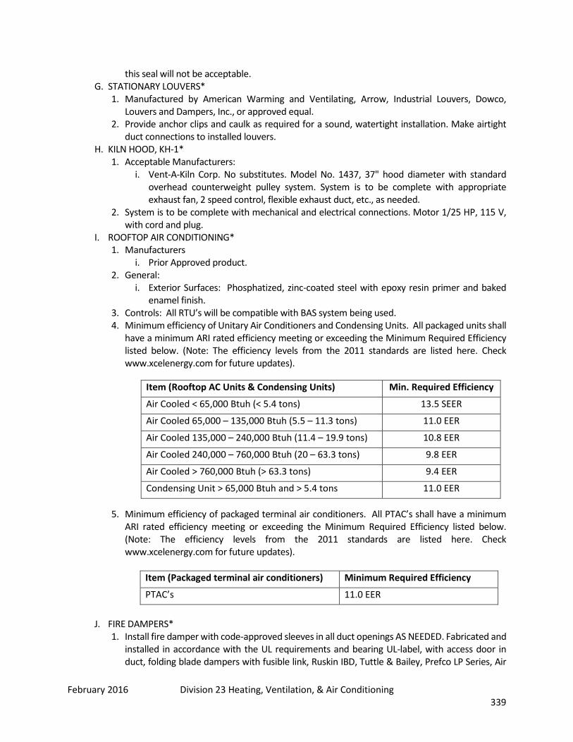
February 2016 Division 23 Heating, Ventilation, & Air Conditioning 339
this seal will not be acceptable. G. STATIONARY LOUVERS*
1. Manufactured by American Warming and Ventilating, Arrow, Industrial Louvers, Dowco, Louvers and Dampers, Inc., or approved equal.
2. Provide anchor clips and caulk as required for a sound, watertight installation. Make airtight duct connections to installed louvers.
H. KILN HOOD, KH-1* 1. Acceptable Manufacturers:
i. Vent-A-Kiln Corp. No substitutes. Model No. 1437, 37" hood diameter with standard overhead counterweight pulley system. System is to be complete with appropriate exhaust fan, 2 speed control, flexible exhaust duct, etc., as needed.
2. System is to be complete with mechanical and electrical connections. Motor 1/25 HP, 115 V, with cord and plug.
I. ROOFTOP AIR CONDITIONING* 1. Manufacturers
i. Prior Approved product. 2. General:
i. Exterior Surfaces: Phosphatized, zinc-coated steel with epoxy resin primer and baked enamel finish.
3. Controls: All RTU’s will be compatible with BAS system being used. 4. Minimum efficiency of Unitary Air Conditioners and Condensing Units. All packaged units shall
have a minimum ARI rated efficiency meeting or exceeding the Minimum Required Efficiency listed below. (Note: The efficiency levels from the 2011 standards are listed here. Check www.xcelenergy.com for future updates).
5. Minimum efficiency of packaged terminal air conditioners. All PTAC’s shall have a minimum ARI rated efficiency meeting or exceeding the Minimum Required Efficiency listed below. (Note: The efficiency levels from the 2011 standards are listed here. Check www.xcelenergy.com for future updates).
Item (Packaged terminal air conditioners) Minimum Required Efficiency
PTAC’s 11.0 EER
J. FIRE DAMPERS*
1. Install fire damper with code-approved sleeves in all duct openings AS NEEDED. Fabricated and installed in accordance with the UL requirements and bearing UL-label, with access door in duct, folding blade dampers with fusible link, Ruskin IBD, Tuttle & Bailey, Prefco LP Series, Air
Item (Rooftop AC Units & Condensing Units) Min. Required Efficiency
Air Cooled < 65,000 Btuh (< 5.4 tons) 13.5 SEER
Air Cooled 65,000 – 135,000 Btuh (5.5 – 11.3 tons) 11.0 EER
Air Cooled 135,000 – 240,000 Btuh (11.4 – 19.9 tons) 10.8 EER
Air Cooled 240,000 – 760,000 Btuh (20 – 63.3 tons) 9.8 EER
Air Cooled > 760,000 Btuh (> 63.3 tons) 9.4 EER
Condensing Unit > 65,000 Btuh and > 5.4 tons 11.0 EER
February 2016 Division 23 Heating, Ventilation, & Air Conditioning 340
Balance 119, United Sheet Metal, National Controlled Air VB and HB, or equal, use frame CR for all round ducts. Use frame B for rectangular and square ducts.
2. Provide ceiling mounted fire dampers to protect grille, register, and diffuser ceiling penetrations where indicated on plans. Unit shall be UL labeled for protection against fire and heat radiation in a roof-ceiling assembly. Damper units shall be Model CFS by National Controlled Air, Inc., or Air Balance Model 219.
3. Major trunk line fire dampers shall have position switch tied into building automation system. K. FIRE/SMOKE DAMPERS*
1. Install fire/smoke damper with code-approved sleeves. Fabricated and installed in accordance with the UL requirements and bearing UL-label, with access door in duct, multiple blade dampers with fusible link and electric operator.
2. Damper to be similar to Prefco Products Inc. Model 5010 with 120-volt electric damper operator Model 5920 with reusable electric McCabe Link and automatic damper reset. Must satisfy UL 33, UL 873, UL 555S, and UL 86A.
3. Damper shall be able to open and/or close in 15 seconds, from signal from smoke detector, and shall fail closed on loss of power.
4. Acceptable Manufacturers: i. Prefco. ii. Ruskin. iii. Tuttle & Bailey. iv. Air Balance. v. United Sheet Metal. vi. National Controlled Air. vii. Or Approved Equal.
L. COMBINATION FIRE/SMOKE DAMPERS WITH INTEGRAL DUCT SMOKE DETECTORS 1. Motor-Driven Smoke Dampers: Provide UL labeled, Class II minimum, motor-driven smoke
dampers in sizes indicated, with casing constructed of 16 gauge steel with bonded red acrylic enamel finish, type 304 stainless steel side seals, stainless steel edge seals, bronze oilite bearings, single lock blades, with damper factory mounted electric motor, stainless steel closing springs, motor mounting bracket, along with the following features. Temperature class 250°F.
2. Out of airstream in-jamb linkage with stainless steel pivots. 3. The electric damper actuator shall be 120-volt, 2-position motor designed to power open and
fail closed. 4. Damper actuator shall fail close upon loss of power. 5. Type B or C housing for respective duct type. 6. U.L. 555 (minimum) 7. Leakage not greater than 10 CFM per square foot at 1" W. C. pressure differential. 8. Integral Duct Smoke Detector: Each fire/Smoke damper shall be provided with a factory
mounted duct smoke detector. Detector shall be photoelectric type, with sampling tube, 120V connection, and auxiliary contacts for fire alarm system connection. Detector shall be suitable for 300-4,000 fpm duct velocity, 32° F to 120°F air temperature.
9. Combination Fire/Smoke Dampers shall be factory-wired to accept 120V service, and fire alarm connections for completely functional damper operation.
10. Ruskin Model FSD60, with DSDF duct smoke detector, or equivalent. Part 3: Execution 3.01 Preparation 3.02 Installation

February 2016 Division 23 Heating, Ventilation, & Air Conditioning 341
A. Hang ducts from beams and joists whenever possible. REGISTERS, GRILLES, AND DIFFUSERS* 1. Adjust air pattern controllers so that drafts are not created. 2. Selection based on NC less than 30.
B. RELIEF/INTAKE HOODS (RH & IH)* 1. Hoods to be manufactured by Penn, Greenheck, Jenn-Air, Loren Cook, Louvers & Dampers, Inc.,
Acme, or approved equal. C. Units shall be furnished complete with birdscreen and anti-condensate coating.
3.03 Cleaning and Protection
END OF SECTION 23 30 00
SECTION 23 31 13 – DUCTWORK
Part 1: General 1.01 Summary
A. Extent of metal ductwork DUCT SERVICE TYPE/CONSTRUCTION Supply air between fan and terminal boxes (medium pressure).
Galvanized steel, spiral, round or rectangular factory fabricated.
Rectangular supply air from discharge of terminal box to air devices (low pressure).
Galvanized sheet metal spiral round or rectangular factory or shop fabricated.
Return air ductwork. Galvanized steel; factory or shop fabricated.
General building exhaust. Galvanized sheet metal; factory or shop fabricated.
Transfer ducts. Internally lined galvanized sheet metal as described above for low pressure supply; factory or shop fabricated.
Sound elbows for R.A. grilles Galvanized sheet metal (internally lined).
Outdoor air intake ductwork. Galvanized sheet metal, rectangular, factory or shop fabricated.
Kitchen grease exhaust. Carbon steel all welded construction per local code and latest NFPA 96. Provide fire-rated external duct wrap as specified.
Exterior uninsulated ductwork. Aluminum or painted galvanized. 1.02 Related Sections 1.03 Definitions 1.04 Submittals Required: Product Data, Shop Drawings, Record Drawings, Maintenance Data 1.05 Quality Assurance
A. Manufacturer's Qualifications: similar service for not less than 5 years. B. Installer's Qualifications: at least 3 years of successful installation C. References to SMACNA, ASHRAE and NFPA are minimum requirements.
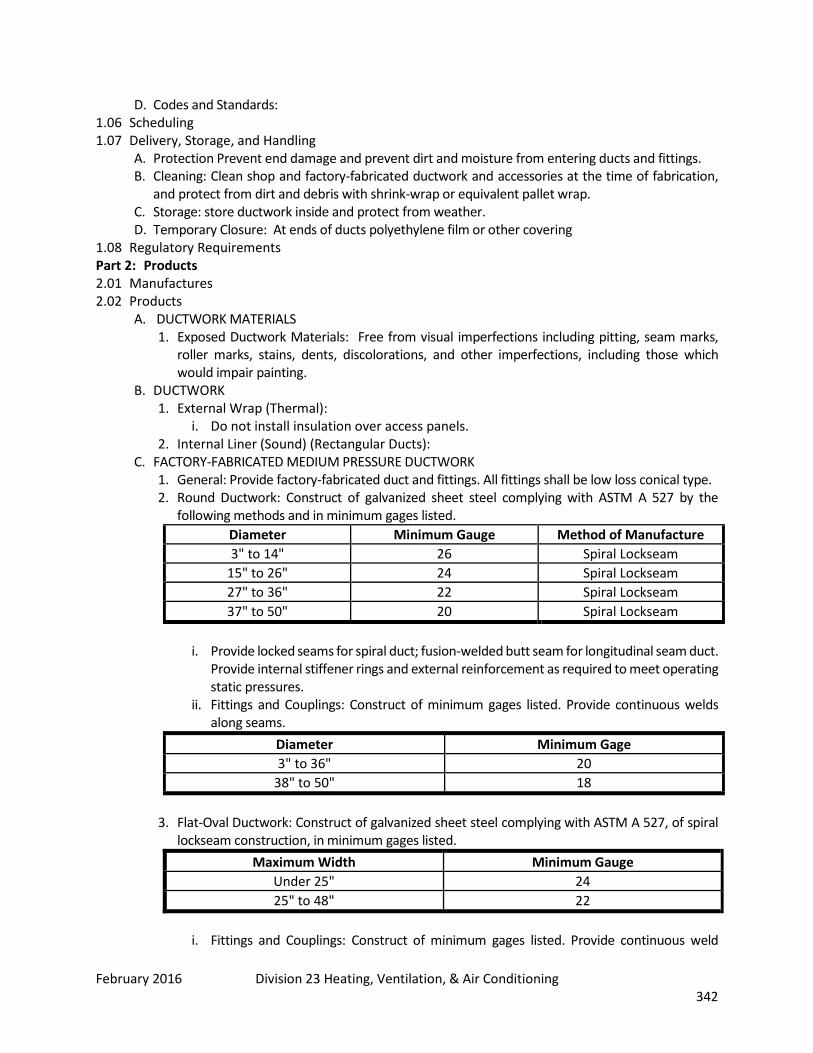
February 2016 Division 23 Heating, Ventilation, & Air Conditioning 342
D. Codes and Standards: 1.06 Scheduling 1.07 Delivery, Storage, and Handling
A. Protection Prevent end damage and prevent dirt and moisture from entering ducts and fittings. B. Cleaning: Clean shop and factory-fabricated ductwork and accessories at the time of fabrication,
and protect from dirt and debris with shrink-wrap or equivalent pallet wrap. C. Storage: store ductwork inside and protect from weather. D. Temporary Closure: At ends of ducts polyethylene film or other covering
1.08 Regulatory Requirements Part 2: Products 2.01 Manufactures 2.02 Products
A. DUCTWORK MATERIALS 1. Exposed Ductwork Materials: Free from visual imperfections including pitting, seam marks,
roller marks, stains, dents, discolorations, and other imperfections, including those which would impair painting.
B. DUCTWORK 1. External Wrap (Thermal):
i. Do not install insulation over access panels. 2. Internal Liner (Sound) (Rectangular Ducts):
C. FACTORY-FABRICATED MEDIUM PRESSURE DUCTWORK 1. General: Provide factory-fabricated duct and fittings. All fittings shall be low loss conical type. 2. Round Ductwork: Construct of galvanized sheet steel complying with ASTM A 527 by the
following methods and in minimum gages listed. Diameter Minimum Gauge Method of Manufacture 3" to 14" 26 Spiral Lockseam
15" to 26" 24 Spiral Lockseam 27" to 36" 22 Spiral Lockseam 37" to 50" 20 Spiral Lockseam
i. Provide locked seams for spiral duct; fusion-welded butt seam for longitudinal seam duct.
Provide internal stiffener rings and external reinforcement as required to meet operating static pressures.
ii. Fittings and Couplings: Construct of minimum gages listed. Provide continuous welds along seams.
Diameter Minimum Gage 3" to 36" 20
38" to 50" 18
3. Flat-Oval Ductwork: Construct of galvanized sheet steel complying with ASTM A 527, of spiral lockseam construction, in minimum gages listed.
Maximum Width Minimum Gauge Under 25" 24 25" to 48" 22
i. Fittings and Couplings: Construct of minimum gages listed. Provide continuous weld
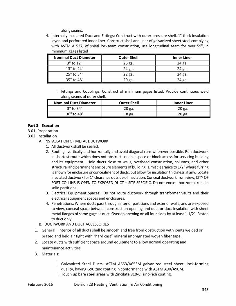
February 2016 Division 23 Heating, Ventilation, & Air Conditioning 343
along seams. 4. Internally Insulated Duct and Fittings: Construct with outer pressure shell, 1" thick insulation
layer, and perforated inner liner. Construct shell and liner of galvanized sheet steel complying with ASTM A 527, of spiral lockseam construction, use longitudinal seam for over 59", in minimum gages listed
Nominal Duct Diameter Outer Shell Inner Liner 3" to 12" 26 ga. 24 ga.
13" to 24" 24 ga. 24 ga. 25" to 34" 22 ga. 24 ga. 35" to 48" 20 ga. 24 ga.
i. Fittings and Couplings: Construct of minimum gages listed. Provide continuous weld
along seams of outer shell. Nominal Duct Diameter Outer Shell Inner Liner
3" to 34" 20 ga. 20 ga. 36" to 48" 18 ga. 20 ga.
Part 3: Execution 3.01 Preparation 3.02 Installation
A. INSTALLATION OF METAL DUCTWORK 1. All ductwork shall be sealed. 2. Routing: vertically and horizontally and avoid diagonal runs wherever possible. Run ductwork
in shortest route which does not obstruct useable space or block access for servicing building and its equipment. Hold ducts close to walls, overhead construction, columns, and other structural and permanent enclosure elements of building. Limit clearance to 1/2" where furring is shown for enclosure or concealment of ducts, but allow for insulation thickness, if any. Locate insulated ductwork for 1" clearance outside of insulation. Conceal ductwork from view, CITY OF FORT COLLINS IS OPEN TO EXPOSED DUCT – SITE SPECIFIC. Do not encase horizontal runs in solid partitions.
3. Electrical Equipment Spaces: Do not route ductwork through transformer vaults and their electrical equipment spaces and enclosures.
4. Penetrations: Where ducts pass through interior partitions and exterior walls, and are exposed to view, conceal space between construction opening and duct or duct insulation with sheet metal flanges of same gage as duct. Overlap opening on all four sides by at least 1-1/2". Fasten to duct only.
B. DUCTWORK AND DUCT ACCESSORIES 1. General: Interior of all ducts shall be smooth and free from obstruction with joints welded or
brazed and held air tight with “hard cast” mineral impregnated woven fiber tape. 2. Locate ducts with sufficient space around equipment to allow normal operating and
maintenance activities. 3. Materials:
i. Galvanized Steel Ducts: ASTM A653/A653M galvanized steel sheet, lock-forming quality, having G90 zinc coating in conformance with ASTM A90/A90M.
ii. Touch up bare steel areas with Zincilate 810-C, zinc-rich coating.

February 2016 Division 23 Heating, Ventilation, & Air Conditioning 344
iii. Duct, fittings and appurtenances shall be manufactured by the Kirk & Blum Manufacturing Company or approved equal.
4. Ductwork:
iv. The following minimum metal thickness shall be applied:
Diameter U.S. Standard Gage for Class 1
Less than 8 inch 22 gage
8 inch to 18 inches 20 gage
20 to 30 inches 18 gage
v. Fabricate and support [to UL 181] in accordance with SMACNA [HVAC Duct Construction Standards - Metal and Flexible 2 inch pressure class, Round Industrial Duct Construction Standard and Rectangular Industrial Duct Construction Standard, and ACGIH Industrial Ventilation Manual.
vi. T's, bends, and elbows shall be welded high-pressure type. C. INSTALLATION OF FLEXIBLE DUCTS
1. Maximum Length: For any duct run using flexible ductwork, do not exceed 5' - 0". D. INSTALLATION OF FIRE-RESISTIVE DUCT WRAP
3.03 Cleaning and Protection A. FIELD QUALITY CONTROL
1. General: i. Ductwork pressure tests shall be observed by Architect/Engineer prior to installation of
insulation. ii. Test Failures.
B. EQUIPMENT CONNECTIONS 1. Provide access doors where required for service, maintenance and inspection of ductwork
accessories.
END OF SECTION 23 31 13
SECTION 23 33 00 – AIR DUCT ACCESSORIES
Part 1: General 1.01 Summary
A. Types of ductwork accessories required for project include the following: 1. Manual Volume Dampers. 2. Control Dampers. 3. Counterbalanced Relief Dampers. 4. Turning Vanes. 5. Duct Hardware. 6. Duct Access Doors.

February 2016 Division 23 Heating, Ventilation, & Air Conditioning 345
7. Flexible Connections. 1.02 Related Sections 1.03 Definitions 1.04 Submittals Required: Product Data, Shop Drawings, Record Drawings, Maintenance Data 1.05 Quality Assurance
A. Manufacturer's Qualifications: not less than 5 years. 1.06 Scheduling 1.07 Delivery, Storage, and Handling 1.08 Regulatory Requirements Part 2: Products 2.01 Manufactures
A. Manufacturer: Subject to compliance with requirements, provide products by one of the following: 1. Combination Fire/Smoke Dampers:
i. Air Balance, Inc. ii. Phillips Industries, Inc. Conaire Division iii. Ruskin iv. Greenheck v. Prefco vi. Nailor Industries vii. Pottorff viii. Approved equal.
2.02 Products A. TURNING VANES
1. Fabricated Turning Vanes: Provide fabricated 22 gauge, single blade or 24 gauge double bladed 4-1/2" radius, 3-1/4" spacing turning vanes and type 2, 4-1/2" wide runners, constructed in accordance with SMACNA "HVAC Duct Construction Standards" Fig 2.3.
2. Manufactured Turning Vanes: Provide airfoil double bladed turning vanes constructed of 1-1/2" wide curved blades set at 3/4" o.c., supported with bars perpendicular to blades set at 2" o.c., and set into side strips suitable for mounting in ductwork.
3. Do not use trailing edge turning vanes. B. DUCT HARDWARE:
1. General: Provide duct hardware, manufactured by one manufacturer for all items on project, for the following:
2. Test Holes: Provide in ductwork at fan inlet and outlet, and elsewhere as indicated, duct test holes, consisting of slot and cover, for instrument tests.
3. Quadrant Locks: Provide for each manual volume damper, quadrant lock device on one end of shaft; and end bearing plate on other end for damper lengths over 12". Provide extended quadrant locks and end extended bearing plates for externally insulated ductwork.
C. DUCT ACCESS DOORS 1. General: Provide access doors, at all fire dampers, smoke dampers, temperature control
dampers, branch balancing dampers, duct heating coils, upstream of all turning vanes, outside air plenums, inlet of fans, upstream of all duct smoke detectors and all other equipment requiring service and/or access.
2. Construction: Construct of same or greater gage as ductwork served, provide insulated doors for insulated ductwork. Provide flush frames for uninsulated ductwork, extended frames for externally insulated duct. All access doors shall have gasket and will be air tight. Provide one side hinged, other side with one handle-type latch for doors 12" high and smaller, 2 handle-
February 2016 Division 23 Heating, Ventilation, & Air Conditioning 346
type latches for larger doors. For spiral ductwork, use United McGill combination access section type ARF-SD for non-insulated duct systems and type ARF-ID double wall insulated door for insulated ducted systems (all supply ductwork).
3. Hand entry access door openings: 24" x 24" minimum if the duct permits. Personnel entry doors: 18" x 42" minimum.
D. ACCESS PANELS* 1. Permit inspection and maintenance of all automatic dampers, fire dampers, control equipment,
coils, and other equipment requiring maintenance. Panels shall not be located in top side of ducts. Ceiling panels to be compatible with type ceiling used.
2. Panels shall be attached to duct with zinc-plated cam latches. 18" x 18" and smaller panels shall have a minimum of two latches. Larger panels shall have a minimum of 4 latches. Panels shall set in rigid frame with sponge rubber gasketing to prevent air leakage. Panels may be of single wall uninsulated construction.
i. Where duct size permits, access panels shall be minimum 18" x 16" or 2" smaller than duct size, whichever is smaller.
E. FLEXIBLE CONNECTIONS 1. General: Provide flexible duct connections wherever ductwork connects to vibration isolated
equipment. Construct flexible connections of neoprene-coated flameproof fabric crimped into duct flanges for attachment to duct and equipment. Make airtight joint. Provide adequate joint flexibility to allow for thermal, axial, transverse, and torsional movement, and also capable of absorbing vibrations of connected equipment. Shelf life shall be verified to not exceed six (6) months. Any sign of cracking on interior or exterior shall be cause for replacement immediately.
2. Flexible Piping shall be used to connect exhaust drop pipes to machines. i. Flexible pipe shall be kept to a length not to exceed 36 inches. ii. Automation Industries, Inc., Flexible Tubing Division, “Spiratube TDS”, nylon cover,
with vinyl scuff straps, galvanized spring steel helix, nylon liner; with operating range of -10 degrees to 200 degrees F; High-Tech type RFH or approved equal.
iii. Use stainless steel clamps and other accessories as required for a complete installation.
Part 3: Execution 3.01 Preparation 3.02 Installation
A. INSTALLATION OF DUCTWORK ACCESSORIES 1. Install access doors to open against system air pressure, with latches operable from either side,
except outside only where duct is too small for person to enter. 2. Provide fire/smoke dampers, where ducts and outlets pass through rated components, and
where required by authorities having jurisdiction. 3. Where fire/ smoke dampers are installed in rated construction, provide firestopping between
fire smoke damper sleeve and substrate. B. FIELD QUALITY CONTROL
1. Test every fire/smoke damper for proper operation, letter REQUIRED certifying this work is complete and all dampers are functioning properly.
3.03 Cleaning and Protection A. ADJUSTING AND CLEANING
1. Label access doors in per label and identification requirements. 2. Final positioning of manual dampers.
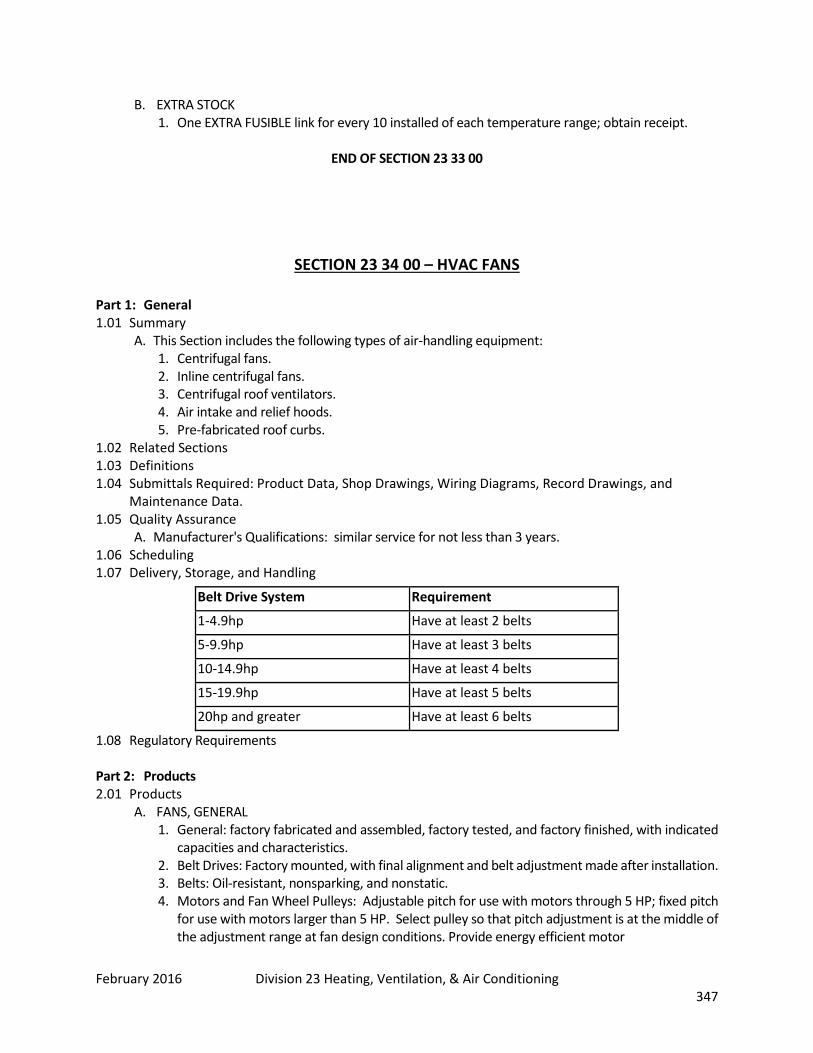
February 2016 Division 23 Heating, Ventilation, & Air Conditioning 347
B. EXTRA STOCK 1. One EXTRA FUSIBLE link for every 10 installed of each temperature range; obtain receipt.
END OF SECTION 23 33 00
SECTION 23 34 00 – HVAC FANS
Part 1: General 1.01 Summary
A. This Section includes the following types of air-handling equipment: 1. Centrifugal fans. 2. Inline centrifugal fans. 3. Centrifugal roof ventilators. 4. Air intake and relief hoods. 5. Pre-fabricated roof curbs.
1.02 Related Sections 1.03 Definitions 1.04 Submittals Required: Product Data, Shop Drawings, Wiring Diagrams, Record Drawings, and
Maintenance Data. 1.05 Quality Assurance
A. Manufacturer's Qualifications: similar service for not less than 3 years. 1.06 Scheduling 1.07 Delivery, Storage, and Handling
1.08 Regulatory Requirements Part 2: Products 2.01 Products
A. FANS, GENERAL 1. General: factory fabricated and assembled, factory tested, and factory finished, with indicated
capacities and characteristics. 2. Belt Drives: Factory mounted, with final alignment and belt adjustment made after installation. 3. Belts: Oil-resistant, nonsparking, and nonstatic. 4. Motors and Fan Wheel Pulleys: Adjustable pitch for use with motors through 5 HP; fixed pitch
for use with motors larger than 5 HP. Select pulley so that pitch adjustment is at the middle of the adjustment range at fan design conditions. Provide energy efficient motor
Belt Drive System Requirement
1-4.9hp Have at least 2 belts
5-9.9hp Have at least 3 belts
10-14.9hp Have at least 4 belts
15-19.9hp Have at least 5 belts
20hp and greater Have at least 6 belts
February 2016 Division 23 Heating, Ventilation, & Air Conditioning 348
i. Belt Guards: Provide steel belt guards for motors mounted on the outside of the fan cabinet.
5. Shaft Bearings: Provide type indicated, having a median life "Rating Life" AFBMA L10 of 200,000 calculated in accordance with AFBMA Standard 9 for ball bearings and AFBMA Standard 11 for roller bearings.
6. Factory Finish: i. Sheet Metal Parts: Prime coating prior to final assembly. ii. 2. Exterior Surfaces: Baked-enamel finish coat after assembly.
Part 3: Execution 3.01 Preparation per manufacturer recommendations 3.02 Installation
A. DEMONSTRATION 1. Demonstration Services: factory-authorized service representative to train Owner's
maintenance i. Procedures and schedules related to start-up and shutdown, troubleshooting, servicing,
preventative maintenance, and how to obtain replacement parts. ii. Familiarization with contents of Operating and Maintenance Manuals.
END OF SECTION 23 34 00
SECTION 23 35 13 – DUST COLLECTION SYSTEMS
Part 1: General 1.01 Summary 1.02 Related Sections 1.03 Definitions 1.04 Submittals Required: Shop Drawings, Product Data, Manufacturer’s Certificate, Operation and
Maintenance Data. 1.05 Quality Assurance
A. QUALIFICATIONS a. Years [documented] experience. b. Installer: minimum three years documented experience.
B. WARRANTY a. Furnish five year manufacturer warranty for dust collection systems.
C. EXTRA MATERIALS a. Two sets of filters for filter separator, TWO SETS OF FILTER BAGS, TWO SETS OF BELTS
FOR EACH FAN. 1.05 Scheduling 1.06 Delivery, Storage, and Handling 1.07 Regulatory Requirements

February 2016 Division 23 Heating, Ventilation, & Air Conditioning 349
Part 1: Products 2.02 Manufactures
A. Products: DUST COLLECTOR
1. NO SHAKERS WILL BE ALLOWED Part 3: Execution 3.01 Preparation 3.02 Installation 3.03 Cleaning and Protection
END OF SECTION 23 35 13
February 2016 Division 23 Heating, Ventilation, & Air Conditioning 350
SECTION 23 36 00 – AIR TERMINAL UNITS Part 1: General 1.01 Summary
A. Types of air terminals specified in this section include the following: 1. Central Air Terminals 2. Shutoff Single Duct 3. Reheat
1.02 Related Sections 1.03 Definitions 1.04 Submittals Required: Product Data, Shop Drawings, Wiring Diagrams, Record Drawings, and
Maintenance Data. 1.05 Quality Assurance
A. Manufacturer's Qualifications: not less than 5 years. 1.06 Scheduling 1.07 Delivery, Storage, and Handling 1.08 Regulatory Requirements Part 2: Products 2.01 Manufactures 2.02 Products Part 3: Execution 3.01 Preparation 3.02 Installation
A. Duct Connections: Connect ductwork to air terminals. 3.03 Cleaning and Protection
END OF SECTION 23 36 00
SECTION 23 37 00 – AIR OUTLETS AND INLETS Part 1: General 1.01 Summary
A. Do not use fiberglass ductwork. B. Ductwork exposed on roofs is strongly discouraged. Review with the owner any proposed exposed
ductwork. C. Do not install turning vanes in unequal ells. Use expansion transitions and duct splits with equal
ells. D. Do not use "extractors" at duct branch takeoffs, use 45-degree standard branch. Extractors may be
used at duct mounted sidewall diffusers. E. Consultant to specify pressure, air speed, and show on drawings using SMACNA standards. F. Do not use splitter dampers.

February 2016 Division 23 Heating, Ventilation, & Air Conditioning 351
G. Include volume control devices required for air balancing on the contract documents. H. Consultant to provide a specific list of work items for renovation of existing equipment and duct
work. Global statements to rehabilitate "as required or necessary" are not acceptable. 1.02 Related Sections 1.03 Definitions 1.04 Submittals Required 1.05 Quality Assurance 1.06 Scheduling 1.07 Delivery, Storage, and Handling 1.08 Regulatory Requirements Part 2: Products 2.01 Manufactures 2.02 Products
A. DUCTWORK Diameter Collar Blade 3" thru 14" 11 14 15" thru 26" 10 12
27" thru 36" 9 10 B. GRILLES, DIFFUSERS, REGISTERS
1. No duct socks allowed C. VARIABLE AIR VOLUME (VAV) BOXES
1. If authorized by the District. Part 3: Execution 3.01 Preparation 3.02 Installation
A. So that duct interiors may be cleaned, external duct wrap insulation is preferred over duct lining. Consider the use of mufflers or sound attenuators to reduce fan noise.
B. Locate manual dampers for diffuser control as far from the diffuser as possible but still in the room or preferably the adjacent corridor to minimize noise.
3.03 Cleaning and Protection
END OF SECTION 23 37 00
SECTION 23 50 00 – CENTRAL HEATING EQUIPMENT Part 1: General 1.01 Summary 1.02 Related Sections 1.03 Definitions 1.04 Submittals Required 1.05 Quality Assurance 1.06 Scheduling 1.07 Delivery, Storage, and Handling
February 2016 Division 23 Heating, Ventilation, & Air Conditioning 352
1.08 Regulatory Requirements Part 2: Products 2.01 Manufactures 2.02 Products
A. STRAINERS 1. Strainers for water, 2" and smaller shall be cast iron or semi-steel, screwed "Y" strainer, 250
lb. construction, and 1/2 inch ball valve with capped hose adapter for blow-down. Strainer shall be Armstrong No. A1SC, or prior approved equal for 2-1/2" and less, Armstrong No. A1FL for 2 1/2" and larger.
2. Screens for water service shall be stainless steel. For strainers 2 inches and less, strainers shall be 20-mesh or 1/32" perforations. For strainers 2 1/2" to 8", mesh shall be perforated brass with 1/16" openings.
B. AIR SEPARATOR* 1. Acceptable Manufacturers:
i. Amtrol. ii. Bell & Gossett (Rolairtrol). iii. Taco. iv. Spyrol Vent (Preferred) v. Approved Equal.
2. Separator shall be the centrifugal type, with strainer, line size, with a Hoffman #79 auto air release valve. 125 psi working pressure. Pipe discharge to floor drain
3. Air separator shall be suitably supported in piping system with clearance provided for strainer removal.
C. AIR VENTS* 1. Provide manual (not automatic) air vent valves at the high point wherever drops occur in
the direction of water flow, at the top of all supply risers and at the high point of return risers on all hot water heating supply and return mains. Air vent ball valves shall be installed on the top of the risers in an accessible location. A 1/4” copper tube shall extend from a reducer provided at the high point to a point where a bucket can be placed to catch any drips. No Armstrong air vents will be allowed. Use Hoffman of applicable size. Or approved equal.
2. Add air vents to high points in RTU piping. 3. Provide isolation ball valves for replacement. 4. The high side of heating elements on up-fed cabinet unit heaters, etc., shall be piped
complete with a 3/4" x 4" high air chamber with a reducer at the top from which a 1/4" copper tube shall be extended to an accessible manual (not automatic) air vent valve as above.
D. BACKFLOW PREVENTER* 1. Acceptable Manufacturers: Watts. Watts 909QT only 2. Shall be the reduced pressure type with atmospheric vent, for boiler water make-up. 3. Bronze body and accessory construction and replaceable seats. 4. Bronze body ball valve test cocks, unions, full port ball valve shut-offs on inlet and outlet,
and bronze inline strainer. 5. Watts Model U909 QTS, 3/4" size with strainer on inlet side and spring check valve on
upstream side. E. EXPANSION TANK*
1. Acceptable Manufacturers:
February 2016 Division 23 Heating, Ventilation, & Air Conditioning 353
i. Amtrol. ii. Armstrong iii. Bell & Gossett. iv. Taco. v. Or approved equal.
2. Tank shall be the elastomeric bladder type, with positive water and air separation, pressurized.
3. Size as specified and as required for proper venting pressure. 4. With vertical mounting support feet, air charging valve, and air pressure gauge. Accessible
floor-type with isolation and union. F. FINNED TUBE RADIATION (FTR-1)*
1. Acceptable Manufacturers: i. American Air Filter. ii. Sterling. iii. Trane. iv. Vulcan. v. Approved Equal.
2. Cover shall be complete with hangers, supports and accessories. Provide end pieces, joining pieces, mounting brackets and accessories as required for a complete installation. Provide end caps. Copper tube and aluminum fins.
3. Enclosure shall be minimum 16-gauge construction, with access panels and factory backed enamel paint. Cover shall also conceal HWS & HWR piping from wall to unit ventilator.
G. FLOW VENTURIS (FV)* 1. Acceptable Manufacturers:
i. Aeroquip Barco. ii. Gerand. iii. Approved Equal.
2. Description: Cast iron or brass body flow measuring device of venturi type with readout plugs constructed for 125 psig working pressure. Provide with nameplate showing capacity data with integral or separate curves of head pressure versus capacity for range of flows.
3. Flow Measuring Device Schedule: Drawing Code Make Model Delta P Flow, GPM Press. Drop FV-1 Barco – – – –
H. HOT WATER HEATING COILS* 1. Acceptable Manufacturers:
i. Airtherm. ii. McQuay. iii. Trane. iv. Approved Equal.
2. Hot water heating coils shall be constructed of 1/2" O.D. minimum copper tubes expanded into aluminum plate fins and cast iron or seamless copper headers. Coil circuiting shall be single tube continuous with same end connection. Casings shall be constructed of 16 gauge galvanized steel with fins recessed into channels to minimize air bypass. Casing shall include -1/2" flanges for duct connections. Coils shall be rated for 150 psig working pressure and shall have capacities and characteristics as scheduled on the plans. Coil water velocity shall not exceed 5 feet per second.
3. Supervise all installations to ensure proper pitch for drainage and venting. Make all
February 2016 Division 23 Heating, Ventilation, & Air Conditioning 354
connections and install all specialties as detailed after installation in duct system. 4. Coils shall be isolated with ball valves and balance valves, installed to allow easy coil
removal. I. HOT WATER HEATING PUMP AND DOMESTIC HOT WATER CIRC PUMPS*
1. Acceptable Manufacturers: i. Taco ii. Bell & Gossett iii. Grundfos Magna to be used whenever possible iv. Patterson Enviroflo
2. Pumps shall have mechanical seals designed for hot water service to 220°F, steel shafts, renewable wearing rings, bronze impellers, and casings designed for 150 PSIG working pressure. Pumps, except close-coupled type, shall have flexible couplings of non-metallic or single barrel spring design. Multiple spring couplers will not be accepted.
i. Provide one (1) extra set of mechanical seals for each pump. ii. Pump manufacturer shall machine the pump impellers, if necessary, to meet capacities
scheduled. Pumps shall be dynamically balanced prior to shipment. iii. Extreme care is to be exercised when installing pumps such that no strain whatsoever
is placed on the mains due to pump position. iv. Motors shall be built for pump service, with electrical characteristics as indicated.
Motors shall have built-in thermal overload protection. And premium efficiency. v. Ball valve isolations on each side of pumps. vi. Install hot water heat pumps on return side to prevent overheating.
3. Domestic Hot Water recirculating pumps shall be the cartridge type, system lubricated, bronze body, and stainless steel shaft, rotor, and faceplate. 1/25 HP. Taco is preferred.
J. UNIT HEATERS* 1. Acceptable Manufacturers: (NO STANDARD UNIVENTS)
Part 3: Execution 3.01 Preparation 3.02 Installation 3.03 Cleaning and Protection
END OF SECTION 23 50 00
SECTION 23 51 00 – BREECHINGS, CHIMNEYS, AND STACKS Part 1: General 1.01 Summary 1.02 Related Sections 1.03 Definitions 1.04 Submittals Required: Product Data, Shop Drawings, Quality Control Submittals, Record Drawings 1.05 Quality Assurance 1.06 Scheduling 1.07 Delivery, Storage, and Handling 1.08 Regulatory Requirements

February 2016 Division 23 Heating, Ventilation, & Air Conditioning 355
Part 2: Products 2.01 Manufactures 2.02 Products Part 3: Execution 3.01 Preparation 3.02 Installation
A. INSTALLATION OF DOUBLE WALL CONNECTORS, BREECHINGS AND VENTS 1. The system shall have a 10" minimum clearance to combustibles with flue gases not exceeding
1000oF continuous. 2. The inner pipe joints shall be field sealed with Containment Bands and high temperature
sealant. 3. Stacks extending above the roof must terminate a minimum of 3'-0" above the roof or parapet
per NFPA 211, or as required by local code. B. INSTALLATION OF DAMPERS
1. Install barometric and thermostatically operated dampers in accordance with manufacturer's instructions. Locate as close to draft hood collar as possible.
3.03 Cleaning and Protection A. ADJUSTING AND CLEANING
1. Clean breechings internally during installation, to remove dust and debris. Clean external surfaces to remove welding slag and mill film. Grind welds smooth.
END OF SECTION 23 51 00
SECTION 23 52 00 – HEATING BOILERS Part 1: General 1.01 Summary
A. Heating water boilers only, no steam except in limited applications in old buildings to replace like equipment.
1.02 Related Sections 1.03 Definitions 1.04 Submittals Required 1.05 Quality Assurance 1.06 Scheduling 1.07 Delivery, Storage, and Handling 1.08 Regulatory Requirements Part 2: Products 2.01 Manufactures 2.02 Products
A. CONTROLS: BAS will be able to interface via backnet with the boiler. 1. Temperature controller capable of interfacing with temperature controls shall be supplied as a
part of the boiler package. Sequence of operation by the Consultant.
February 2016 Division 23 Heating, Ventilation, & Air Conditioning 356
2. Water Boiler Standard Controls: i. Low limit (operating) temperature control. ii. High limit temperature control. iii. Combination pressure-temperature-altitude gauge(s) to indicate boiler water
temperature, system pressure, and elevation. iv. ASME certified pressure relief valve(s) set to 50 psi, ASME working pressure. v. Low water cut-offs, McDonnell Miller No. 63, as required by codes, with test and check
valves. 3. The boiler shall be furnished with a factory-constructed wiring harness to facilitate wiring
the electrical safety controls into the limit control circuits. Provide the following indication/warning lights:
i. Call for heat light. ii. Main burner "ON." iii. Pilot burner "ON." iv. Failure lights to indicate burner lock out for any reason, magnetic starter trip-out, low
water cut-out, or manual high limit trip-out. 4. High-Low Fire Control:
i. The boiler shall be furnished with a water temperature controller and/or proportional staging control to control the high fire operator of the operating gas valve.
ii. Control shall be adjusted to permit low-fire and high-fire control. iii. Actual control of the high/low firing shall be done through the control system.
B. At least two sections with inspection and cleanout tappings on each end. C. Full opening and removable access doors at each end.
1. ACCEPTABLE MANUFACTURERS: i. Camus ii. Buderis iii. Burnham. iv. Weil-McLain. v. Aerco vi. Dedietrich for cast iron sectional vii. Or approved equal
D. BURNER 1. Acceptable Manufacturers:
i. Power Flame. ii. Approved Equal - Burner shall be capable of delivering the necessary air at 5000 ft.
elevation for proper combustion, to pressurize the firebox and to deliver sea level Btuh output at 5000 ft. elevation.
2. Burner startup and combustion test: i. Factory-authorized technician shall perform start-up. ii. A complete combustion test report shall be submitted to the Engineer indicating the
following: a. Percent of Carbon Dioxide (CO2). b. Stack temperature. c. Stack pressure. d. Room temperature. e. Manifold gas pressure.
3. Boiler shall have an input and gross output as scheduled when fired with natural gas. Boiler shall be tested for and shall bear ASME symbol for low pressure heating boiler, 85%
February 2016 Division 23 Heating, Ventilation, & Air Conditioning 357
minimum efficiency. 4. Minimum efficiency of Boilers. All packaged boilers shall have a minimum ARI rated efficiency
meeting or exceeding the Minimum Required Efficiency listed below. (Note: The efficiency levels from the 2011 standards are listed here. Check www.xcelenergy.com for future updates).
Item (Boiler) Minimum Required Efficiency Non-Condensing Boiler 85% AFUE Condensing Boiler 92% AFUE
Part 3: Execution 3.01 Preparation 3.02 Installation
A. Provide a single 4" minimum raised reinforced concrete housekeeping pad for all boiler units that rest on top of the boiler room floor.
B. Boiler shall be field assembled. Boiler shall be complete with air eliminator, insulated jacket, cast iron sections, forced draft burner, approved gas train, pressure relief valve, and controls. With pressurized fire box for forced draft venting.
3.03 Cleaning and Protection
END OF SECTION 23 52 00
SECTION 23 55 00 – FUEL-FIRED HEATERS Part 1: General 1.01 Summary
A. Types of fuel-fired heaters specified in this section include the following: 1. Gas-Fired Propeller Unit Heaters.
1.02 Related Sections 1.03 Definitions 1.04 Submittals Required: Product Data, Shop Drawings, Wiring Diagrams, Record Drawings, and
Maintenance Data. 1.05 Quality Assurance
A. Manufacturer's Qualifications: not less than 5 years. 1.06 Scheduling 1.07 Delivery, Storage, and Handling 1.08 Regulatory Requirements Part 2: Products 2.01 Manufactures 2.02 Products
A. GAS-FIRED PROPELLER UNIT HEATERS Part 3: Execution 3.01 Preparation 3.02 Installation

February 2016 Division 23 Heating, Ventilation, & Air Conditioning 358
A. INSTALLATION OF GAS-FIRED PROPELLER UNIT HEATERS B. START-UP
3.03 Cleaning and Protection
END OF SECTION 23 55 00
SECTION 23 57 00 – HEAT EXCHANGERS FOR HVAC Part 1: General 1.01 Summary
A. Types of heat exchangers specified in this section include the following: 1. Water-to-Water Plate and Frame Heat Exchanger.
1.02 Related Sections 1.03 Definitions 1.04 Submittals Required: Product Data, Shop Drawings, Record Drawings, and Maintenance Data. 1.05 Quality Assurance
A. Manufacturer's Qualifications: not less than 5 years. 1.06 Scheduling 1.07 Delivery, Storage, and Handling 1.08 Regulatory Requirements Part 2: Products 2.01 Manufactures 2.02 Products
A. WATER-TO-WATER PLATE AND FRAME HEAT EXCHANGER: 1. Units shall be ASME rated for 125 psig operating pressure, 300 deg. F. (149 deg. C) maximum
temperature. Part 3: Execution 3.01 Preparation 3.02 Installation 3.03 Cleaning and Protection
END OF SECTION 23 57 00
SECTION 23 60 00 – CENTRAL COOLING EQUIPMENT Part 1: General 1.01 Summary
A. DESCRIPTION 1. Air cooled condensing units. 2. Refrigerant piping and specialties. 3. Cooling Towers.

February 2016 Division 23 Heating, Ventilation, & Air Conditioning 359
4. Chillers. B. For new buildings or those receiving a major replacement of mechanical equipment or others
authorized for refrigeration cooling: 1. About 50,000 square feet or larger, use chilled water and cooling towers or evaporative
condensers. 2. 20,000 square feet and less, use DX equipment. 3. Others use either type of equipment or air cooled chillers depending on the building's use and
the Engineer's analysis. 4. Design a separate DX unit for the administration area to be used during extended hours when
the rest of the building is unoccupied. This option may not be required if the building cooling plant has a chiller which may be turned down far enough to match the Admin. area load.
C. Direct expansion (DX) systems should be RTU’s D. Major remodels of existing buildings without air conditioning will have that capacity added in the
remodel. Confer with the District at the time of design. Add-on units must be split systems with low speed fans to reduce noise to a minimum.
E. Special design considerations shall be given for server room cooling installations. Systems shall be right sized according to the application and consider outdoor air use. Special considerations include:
1. Setpoints are different than those set for thermal comfort. IT equipment and server room setpoints shall be 70oF.
2. Design shall consider exhaust and heat removal from server rooms. 3. Design shall consider point-specific airflow for racks. 4. Equipment closets shall be considered different than server room closets in design. 5. Design shall observe a hot aisle cold aisle configuration.
1.02 Related Sections 1.03 Definitions 1.04 Submittals Required 1.05 Quality Assurance 1.06 Scheduling 1.07 Delivery, Storage, and Handling 1.08 Regulatory Requirements Part 2: Products 2.01 Manufactures 2.02 Products
A. REFRIGERATION SPECIALTIES 1. Filter-dryers
B. AIR COOLED CONDENSING UNIT All to have hail guards (RTU, and split systems) C. AUTHORIZED TYPES: CHILLER
1. Less than 100 tons: Reciprocating or screw. 2. 140 tons and larger: Centrifugal. 3. Between 100 and 140 tons: Determined by the consultant and the District. 4. Minimum efficiency of Chillers. All packaged chillers shall have a minimum ARI rated efficiency
meeting or exceeding the Minimum Required Efficiency listed below. (Note: The efficiency levels from the 2011 standards are listed here. Check www.xcelenergy.com for future updates).
Item (Chillers) Min. Required Efficiency

February 2016 Division 23 Heating, Ventilation, & Air Conditioning 360
Scroll or Rotary Screw < 150 tons 0.74 kW/ton
Scroll or Rotary Screw > 150 tons and < 300 tons 0.67 kW/ton
Air Cooled 10.0 EER
Water Cooled Centrifugal Must improve on IECC 2006 baseline by 0.016 kW/ton
D. APPLICABLE TO ALL THREE TYPES
1. The preferred power is 460v, 3ph, 60hz. If 460 volt power is not available, 230 or 208 volt is acceptable. No single phase equipment.
2. Single Factory Package: i. Refrigerant compressor(s). (Minimum of two) ii. Water cooled shell and tube refrigerant condenser. iii. Evaporator. iv. Expansion valve. v. Electric drive motors for the compressor(s) and the oil pump. vi. Controls mounted within a common panel. vii. Water cooled oil cooler and oil circulating pump. viii. Electric oil preheater.
3. Applicable Standards and Regulations: i. ANSI - American National Standards Institute (Safety Codes for Mechanical Refrigeration). ii. ARI - Air Conditioning and Refrigeration Institute - (All applicable equipment rating and
construction standards). iii. ASME - American Society of Mechanical Engineers - (Boiler and Pressure Vessel Code,
Section VIII, Division 1, latest edition). iv. NEC - National Electrical Code. v. NEMA - National Electrical Manufacturer's Association - (Motors for Hermetic
Refrigeration Compressors). vi. ARI factory performance test required for chillers > 100 tons. vii. ASHRAE - Standard 15, Safety Code for Mechanical Refrigeration.
4. Design chilled water supply temperature > 47°F. 5. Design condenser water temperature < 73°F. 6. The liquid being chilled and the condenser cooling liquid will be strained water containing
biocides and anti-scaling compounds. 7. Self-excited vibration velocity < 0.10 inch/second in any of the three axes. 8. Heat exchanger fouling factor: 0.0005. 9. Target efficiency: 0.62 KW/ton (centrifugal), 0.70KW/ton (screw) or 0.82KW/ton
(reciprocating) at full rated load under the service conditions specified. Examine part load efficiency figures and base specify the optimal machine.
10. Evaporator: i. Shell-and-tube design with seamless copper tubes and designed, manufactured, tested
and stamped in accordance with Section VIII, Division 1, latest edition of the ASME Boiler and Pressure Vessel Code and its addenda.
ii. Shell: Carbon steel plate, incorporate rupture disc conforming to ANSI/ASHRAE 15-1978 Safety Code, and be furnished with a 150 psig cast-iron water box. Factory-applied thermal insulation.
iii. Positive liquid and vapor seal between the refrigerant and water side of the shell. iv. Copper tube wall thickness: 0.035 inch.
February 2016 Division 23 Heating, Ventilation, & Air Conditioning 361
v. Position intermediate tube support sheets along the length of the shell to avoid contact and relative motion between adjacent tubes.
vi. Use multiple layers of metal mesh screen or some other device to form an eliminator to be installed over the tube bundle along the entire length of the evaporator to prevent liquid refrigerant carryover into the compressor.
11. Water Cooled Condenser: i. Shell and tube design with seamless copper tubes, integral fins. Stamp in accordance with
Section VIII, Division 1, latest edition of the ASME Boiler and Pressure Vessel Code.- ii. Position intermediate tube support sheets along the length of the shell to avoid contact
and relative motion between adjacent tubes. iii. Copper tube wall thickness: 0.035 inch.
12. Purge system to operate automatically for removing any noncondensables and water vapors which may be present in the refrigerant system. Automatic noncondensable discharge and refrigerant return. Remove water with a manual blow-off valve.
13. Controls and Safeties: i. Completely prewired control panel mounted on the chiller assembly:
a. 120V single phase/60 Hz with its own transformer. b. Numbered terminal strip for field interlock wiring. c. Individually numbered and color coded panel wires. d. Number wires same as the manufacturer's circuit drawings. e. Chiller shall have BACnet capabilities.
ii. Automatic safety shutdown with a pilot light and a manual reset each for low evaporator refrigerant temperature, high condenser pressure, high motor temperature and low oil pressure.
iii. Capacity control mechanisms to limit maximum amperage drawn by the compressor. Set point of the compressor demand limit adjustable to any value between 40 and 100% of full load.
iv. Individual dial-type pressure gauges to indicate purge drum, condenser, evaporator and oil pressures.
v. Anti-recycle timer to ensure safe intervals between successive compressor starts. vi. Panel-mounted meters to indicate total number of compressor starts and elapsed
running time. A system pilot light to indicate control power "ON" to the panel. vii. Pilot Lights:
a. Start-up in progress. b. Anti-recycle timer active. c. Condenser water pump on. d. Chilled water pump on. e. Oil pump on. f. Chiller on.
viii. Adjustable Temperature Controls: a. Deadband. b. Chilled water supply temperature set point between 45°F and 55°F.
ix. Wire safety controls to the starter to stop the chiller if: a. Low evaporator temperature. b. High condenser pressure. c. High compressor motor temperature. d. Low oil pressure. e. Loss of condenser water flow.

February 2016 Division 23 Heating, Ventilation, & Air Conditioning 362
f. Loss of chilled water flow. g. Imminent freezing of chilled water.
x. Include a device to reset the chilled water supply temperature set point from the return water temperature. Incorporate a minimum of two field adjustable reset schedules into the controls to match any application with the reset schedule.
xi. Permit automatic chiller unloading during periods when the load decreases below the normal operation. Automatically restart upon an increase in load.
xii. Provide connections to automatically start and stop or demand limit the chiller from a future remote energy management device.
xiii.Provide the capacity to unload the chiller from a remote signal. xiv. Compressor motor starter: Factory mounted, wired and tested on the chiller. Free
standing starters requiring field wiring are not acceptable unless mounted next to the chiller. Include an electronic motor protection system to monitor and protect against the following conditions:
a. Overload. b. Phase unbalance. c. Distribution fault protection to prevent reconnection of the compressor motor while
it is out-of-phase with the line voltage. If a distribution fault is detected, the fault trip indicator shall be displayed and manual reset shall be required. Distribution faults of 1-1/2 electrical cycle durations shall be detected and the compressor motor shall be disconnected within six electrical cycles.
xv. Manually reset high and low refrigerant pressure cutout switches. xvi. Relief valve in compressor discharge circuit. No valves between the compressor
discharge and the relief valve. xvii. Interlocks that will permit field connections from these interrupt signals:
a. The compressor motor power interrupted on loss of cooling or chilled water flow. b. The compressor motor cannot start until the chilled water pump and cooling water
pump are operating. xviii. Disconnect switch mounted on the frame near the starter. xix. Furnish with chilled and condenser water flow switches. xx. An ammeter for each electrical power phase. xxi. Provide for refrigerant recovery.
14. Vibration Isolators: i. Free-standing, laterally stable without any housing, and complete with acoustical friction
pads between the baseplate and the support. 15. 5 year warranty on all reciprocating compressors. 16. Comply with the latest CFC regulations.
E. SPLIT SYTEMS: 1. Minimum efficiency of split systems. All packaged split systems shall have a minimum ARI
rated efficiency meeting or exceeding the Minimum Required Efficiency listed below. (Note: The efficiency levels from the 2011 standards are listed here. Check www.xcelenergy.com for future updates).
Item (Split systems) Minimum Required Efficiency Split System < 65,000 Btuh and < 5.4 tons 14.0 SEER
Part 3: Execution 3.01 Preparation

February 2016 Division 23 Heating, Ventilation, & Air Conditioning 363
3.02 Installation A. START-UP
1. Provide factory start up services for the chiller and the tower. 3.03 Cleaning and Protection
END OF SECTION 23 60 00
SECTION 23 65 13 – FORCED-DRAFT COOLING TOWERS
Part 1: General 1.01 Summary
A. This section includes factory-assembled and -tested, open-circuit, induced-draft, cross-flow cooling towers.
1.02 Related Sections 1.03 Definitions 1.04 Submittals Required: Product Data, Shop Drawings, Wiring Diagrams, Coordination Drawings,
Product Certificates, Field Quality Control Test Reports, Operation and Maintenance Data, Warranties.
1.05 Quality Assurance A. Warranty Period: Five years from date of Substantial Completion.
1.06 Scheduling 1.07 Delivery, Storage, and Handling 1.08 Regulatory Requirements
Part 2: Products 2.01 Manufactures 2.02 Products
A. HANDRAILS, LADDERS, AND PLATFORMS 1. Platforms: Galvanized steel with a bar grating floor.
Part 3: Execution 3.01 Preparation 3.02 Installation
A. CONNECTIONS 1. Install flexible pipe connectors at final connections of towers.
B. STARTUP SERVICE 1. Engage a factory-authorized service representative to perform startup service. 2. Verify operation of tower basin automatic blowdown, and controlling device. 3. Prepare a written startup report that records the results of tests and inspections.
C. ADJUSTING 1. Set and balance water flow to each tower inlet. 2. Adjust water-level control for proper operating level. 3. Occupancy Adjustment: MAY BE REQUIRED – TBD PER PROJECT.
D. DEMONSTRATION 1. Engage a factory-authorized service representative to train Owner's maintenance personnel to
adjust, operate, and maintain cooling towers. 3.03 Cleaning and Protection

February 2016 Division 23 Heating, Ventilation, & Air Conditioning 364
END OF SECTION 23 62 13
SECTION 23 71 20 – GLYCOL SYSTEMS
Part 1: General 1.01 Summary
A. Types of glycol system specialties specified in this section include the following: 1. Propylene glycol 2. Feed Pump 3. Provide glycol feeder for all new construction and anytime a boiler room is being upgraded.
Engineer to size the feeder. Axiom Industries LTD or equal. 4. Provide a combination pot feeder and filter system with filter socks unless previously installed
by owner. Typical of an Eaton unit. 1.02 Related Sections 1.03 Definitions 1.04 Submittals Required: Product Data, Maintenance Data, Test Results. 1.05 Quality Assurance 1.06 Scheduling 1.07 Delivery, Storage, and Handling 1.08 Regulatory Requirements Part 2: Products 2.01 Manufactures
A. Inhibited Propylene Glycol Solution: 1. Chillsafe 2. Dow
2.02 Products A. GLYCOL SYSTEM
1. GLYCOL TRANSFER PUMP i. Provide a Hand-Operated Rotary Transfer Pump with 8 feet of 1 inch hose and a non-
sparking 3/4" nozzle for the transferring of glycol from the glycol container to the glycol feed tank. The pump shall have a 1 inch telescoping suction pipe, and bung adapter with 2 inch thread.
B. GLYCOL SOLUTION 1. Heating Water System:
i. Provide 30% glycol solution suitable to a temperature of -20°F. ii. Provide on extra 55 gallon drum of propylene glycol.
2. Chilled Water System: i. Provide 30% propylene glycol solution. ii. Provide one extra 55 gallon drum of propylene glycol.
Part 3: Execution 3.01 Preparation 3.02 Installation

February 2016 Division 23 Heating, Ventilation, & Air Conditioning 365
A. Thoroughly clean and flush system before adding propylene glycol solution. B. Feed propylene glycol to system through make-up line with pressure regulator. Set to fill at 10 psi
(69 kPa). C. Perform tests determining strength of propylene glycol solution before system is turned over to the
Owner. Provide test prior to end of the first year of operation and replenish as required. 3.03 Cleaning and Protection
END OF SECTION 23 71 20
SECTION 23 72 00 – OUTDOOR AIR VENTILATION (AIR TO AIR SYSTEMS)
Part 1: General 1.01 Summary 1.02 Related Sections 1.03 Definitions 1.04 Submittals Required 1.05 Quality Assurance 1.06 Scheduling 1.07 Delivery, Storage, and Handling 1.08 Regulatory Requirements
Part 2: Products 2.01 Manufactures 2.02 Products
A. Ventilation Outdoor Air Control 1. Minimum ventilation outdoor air control.
i. Variable air volume systems shall have a positive means to maintain minimum outdoor air rates regardless of supply air volume. Setting a fixed minimum outdoor air damper position shall not be acceptable. Acceptable means include:
a. Separate minimum damper set points for design supply air volume and minimum supply air volume, as indicated by fan speed or other supply air duct static pressure controller. [Note to designer: this is the least accurate method, but least expensive and available as standard on some packaged units.]
b. Outdoor airflow measuring station designed to be ±10% accurate at minimum airflow rates, used to modulate outdoor air and/or return air dampers to maintain minimum outdoor air flow rates.
c. Differential pressure sensor across fixed minimum outdoor air damper with set point calibrated to correspond to minimum outdoor air rate, used to modulate return air dampers to maintain minimum outdoor airflow rates.
Part 3: Execution 3.01 Preparation 3.02 Installation 3.03 Cleaning and Protection
END OF SECTION 23 72 00

February 2016 Division 23 Heating, Ventilation, & Air Conditioning 366
SECTION 23 74 00 – PACKAGED OUTDOOR HVAC EQUIPMENT Part 1: General 1.01 Summary
A. Outdoor air handling units. 1.02 Related Sections 1.03 Definitions 1.04 Submittals Required: Product Data, Wiring Diagrams, Record Drawings, Maintenance Data 1.05 Quality Assurance
A. Manufacturer's Qualifications: not less than 5 years. 1.06 Scheduling 1.07 Delivery, Storage, and Handling 1.08 Regulatory Requirements Part 2: Products 2.01 Manufactures
A. Outdoor Air Handling Units – All must be approved by CITY OF FORT COLLINS 2.02 Products
A. OUTDOOR AIR HANDLING UNITS 1. Disposable Type: Provide disposable type air filters 2" thick, consisting of viscous coated fibers
with filtering media encased in fiberboard cell sides having perforated metal grids on each side to provide media support.
Part 3: Execution 3.01 Preparation 3.02 Installation
A. EXTRA STOCK 1. Obtain receipt from Owner that new filters have been installed AT THE END OF THE
CONSTRUCTION BEFORE OWNER TAKE OVER. B. TRAINING – REQUIRED
3.03 Cleaning and Protection
END OF SECTION 23 74 00

February 2016 Division 23 Heating, Ventilation, & Air Conditioning 367
SECTION 23 81 43 – HEAT PUMPS
Part 1: General 1.01 Summary 1.02 Related Sections 1.03 Definitions 1.04 Submittals Required: Shop Drawings, Product Data, Manufacturer’s Certificate, Operation and
Maintenance Data. 1.05 Quality Assurance 1.06 Scheduling 1.07 Delivery, Storage, and Handling 1.08 Regulatory Requirements Part 2: Products 2.01 Manufactures
A. WaterFurnace International, Inc. (PREFERRED) B. ClimateMaster, Inc.
2.02 Products 1. UNITARY HEAT PUMP UNITS: Minimum efficiency of Heat Pumps. All packaged heat
pumps shall have a minimum ARI rated efficiency meeting or exceeding the Minimum Required Efficiency listed below. (Note: The efficiency levels from the 2011 standards are listed here. Check www.xcelenergy.com for future updates).

February 2016 Division 25 Integrated Automation 368
DIVISION 25: Integrated Automation
SECTION 25 00 00 – INTEGRATED AUTOMATION Part 43: General 43.01 Summary
A. Design Documents 1. Preassembled Control Panels. 2. Actuators, thermostats, sensors, thermowells, instrument air compressors, filter/dryers, gages
and mounting hardware as applicable. 3. Control valves, dampers, linkages and mounting hardware. 4. Construction supervision. 5. Demonstration and training. 6. Warranty.
43.02 Related Sections 43.03 Definitions 43.04 Submittals Required
A. Shop drawings, manufacturer's data, and/or printouts for: B. System sequence of operation.
43.05 Quality Assurance 43.06 Scheduling 43.07 Delivery, Storage, and Handling 43.08 Regulatory Requirements
A. New buildings and major remodel projects will use all direct digital controls. Controls in minor retrofits will match the existing controls, whether pneumatic or electronic.
B. The Controls Contractor shall be a fully owned subsidiary of the control manufacturer or factory authorized installer of the major control components and has been in continuous business for at least five years.
C. Design a separate temperature control zone with its own thermostat or control sensor for each student area or classroom.
D. Direct digital or electronic controls are limited at this time to Control System International (CSI) or Delta Controls including those supplied with packaged air handling units.
E. Minimum Design Requirements for Consultants: 1. Include the listed temperature control drawings among the final contract drawings and make
them the same size and of the same sheet material as the other contract drawings no matter what their source, consultant or installing contractor. The mechanical engineer, not the controls contractor, is responsible to see that control drawings meet this standard.
i. Floor and roof plan showing thermostat and equipment locations. ii. Require point-to-point connection diagrams for wiring or pneumatic tubing from the
Controls Contractor. iii. Schematic instrumentation and control flow diagram labeled accurately and showing the
interrelationship of all controls and the areas and equipment served. iv. Show the sequence of operation on the contract documents. The bill of materials shall

February 2016 Division 25 Integrated Automation 369
appear on the Control Contractor's drawings. Part 44: Products 44.01 Manufactures 44.02 Products
A. CONTROL VALVES 1. Flanged cast iron in sizes 2-1/2" and larger, otherwise bronze. Seat and inner valve material of
hardened steel. Sizes 2" and smaller with soldered or threaded connections. 2. Spring return to the normal position in the absence of control power, that is, fail with the
heating valves open and the cooling valves closed. 3. Modulating electric actuators with adjustable end switches to prevent overstroking are
acceptable in sizes <1". Use electric actuators for larger sizes. In remodel projects where no instrument air compressor exists, consult the City.
4. Use a three-way design at the ends of long runs to keep piping near the service temperature and maintaining pump flow above 25% of design. Otherwise use two-way valves.
5. Size for a 5 PSI maximum drop. B. DAMPER ACTUATORS
1. Modulating in most applications or two-position in rare cases; i.e., minimum outside air dampers or exhaust dampers.
2. Provide position indication or verification on the outside air, return air and exhaust air dampers of air handling units larger than 15,000 cfm. An example is an analog input to the DDC panel from an actuator potentiometer.
3. Provide at least one operator for each 16 square feet of damper, or for each length greater than 48".
4. Modulating electric actuators with adjustable end switches to prevent overstroking are acceptable in small dampers associated with unitary equipment like exhaust fans. Consult the City if exceptions are desired or in remodel projects where no instrument air compressor exists.
5. 4-20 mA, 24 vac or 0-20 vdc for electric. Do not use 24 vdc if the actuator position has to be reported.
6. Spring return to the fire alarm position upon power failure. 7. VAV box actuators: capable of permanent stall operation without damage. Adjustable stop pins
for stroke limits. Drive gears of nickel steel, no plastic. C. INDICATORS
1. Interface each indicator with remote sensor/controller to display measured value. 2. Supply selector switches for multiple indicators that show which variable is being measured. 3. Accurate and repeatable to ±0.5% of the measured variable's maximum value. 4. Electro mechanical device or panel mounted back screen display. 5. Indicators are not required for values that can be reported by the DDC system.
D. TRANSDUCERS 1. Electronic transducer: Accuracy ±1% of maximum value. 2. Fully adjustable (not fixed) range. 3. Approved manufacturers: Johnson EPT-101 or 102 or Triac Tech CP-3000 Series. Submit others
to City for approval. E. SENSORS
1. Temperature: Thermistor or platinum RTD, Accuracy ±1°F. Do not use RTDs that require transmitters.
2. Differential Building Static pressure: vary output voltage linearly. Range: -0.1 to 0.1" W.C. with
February 2016 Division 25 Integrated Automation 370
an accuracy of 2% of its range, repeatable to 0.5% of range. 3. Duct static pressure: vary output linearly. Range -1 to +4" W.C., accuracy 3% of range,
repeatable within 1.5% of range. 4. Air velocity: linear indication of the velocity of air in a duct from 0 to 2000 FPM, Accuracy, ±50
FPM from which the central controller can calculate CFM. 5. Outdoor air temperature: high resistance change versus temperature change, designed for
outdoor mounting insulated from the building and out of the sun, minimum range –20 to +110°F, accuracy ±1°F, repeatable within 1/2°F.
6. Room temperature: minimum range 50°F to 95°F, accuracy ±1°F, repeatable 1.5% of range. 7. Duct temperature: minimum range 32°F to 110°F, accuracy ±1°F, repeatable 1.5% of range. Use
averaging elements, not bulbs. 8. Liquid temperature: insert in a pipe well and immerse in a substance designed to enhance heat
transfer and rapid response. Minimum range 35°F to 220°F, 1% accuracy, repeatable within 1% of range.
F. MISCELLANEOUS DEVICES 1. Smoke detectors 2. Freeze Detection Thermostats (Freeze Stats):
i. Line voltage liquid-filled type responsive only to the lowest temperature sensed along any one foot length of its element.
ii. Adjustable. iii. Manual reset.
3. Plastic laminate labels on all panels and major field devices screwed or riveted to the panel faces, no adhesives. Do not attach labels to replaceable devices or room thermostats or sensors. The definition of major is left to the consultant.
4. Flow Switches: i. Pressure differential type with SPDT contacts. Do not use paddle switches except where
required to maintain a chiller or boiler warranty or where other devices would not work reliably. If in doubt, check with the City. The engineer must include a detail of paddle switch installation, if they are used, and assure that the contractor installs them properly. Use McDonnell-Miller FS4-3 or approved equal.
ii. Design an excessive water make-up alarm to alert the maintenance people of too much makeup water flowing into a closed heating or cooling loop and thus indicating a major leak. In systems with a glycol feeder this may be no more than a low level alarm in the glycol tank. In systems that lack a feeder design a DP switch across the backflow preventer or the makeup solenoid valve that will trip with water flow. Add a time delay relay adjustable from 30 to 120 seconds to prevent nuisance alarms.
iii. Use current switches to prove fan or low head pump flow where appropriate. 5. Wind dampening "weatherhead" on each atmospheric pressure sensing point; e.g., Dwyer A-
306. Locate above wind eddies caused by the building structure and roof equipment. 6. Shielded cable on critical communication and sensor lines as recommended by the
manufacturer or advised by the consultant. 7. For afterhours operations provide override timers (6 hour wind-up) that interrupt the
programmed sequence and permit equipment to operate in the occupied mode for programmable temporary intervals. The electric power demand limiting program takes precedence over any override. Locate the timers next to the central DDC controller, mounted in their own panel.
8. Place thermostats or temperature control sensors inside locking clear plastic covers that

February 2016 Division 25 Integrated Automation 371
discourage tampering and vandalism at all locations in Middle and High Buildings. Not required in administration buildings, or anywhere in elementary buildings except gyms. Use surface mounted sensors mounted on interior walls, installed with necessary insulation from wall.
9. Use DP switches across fans as fan status input points into the DDC panel. 10. In buildings with control air compressors, provide a 24 hour blowdown timer on the receiver
tank positioned to automatically open a solenoid valve for an adjustable 4 to 30 seconds once a day.
Part 45: Execution 45.01 Preparation 45.02 Installation
A. The Controls Contractor is responsible for preassembling and installing panels and all hardware with his own employees, proving the system and training City people in its proper function and maintenance.
B. Wiring, conduit placement and the installing of actuators and related linkage may be subcontracted to a City approved installer but in this case the controls contractor shall label and connect all wiring terminations and be responsible for the subcontractor's work.
C. DEMONSTRATION AND TRAINING 1. 12 hours at each elementary or 18 hours at each middle or high building to demonstrate the
controls to City personnel and answer questions. 2. Optionally 24 hours minimum of formal classroom training to City personnel in the theory,
function and application of each hardware and software element and each component in the control system, plus 8 hours of telephone consultation.
3. The consultant shall confer with the City at the time of design to determine how much training will be required by the construction documents.
D. Plenum rated cable inside of plenums. Wiring suspended neatly from the overhead structure. Do not support on top of ceiling tiles. Minimum wire size, 18 AWG stranded.
E. Number or color code wiring terminals and provide a cross reference to ease later checkout and diagnosis.
F. Place exposed control wiring in conduit with proper identification. G. SENSORS
1. Surface mount with standard plastic covers with exposed knobs only in classrooms to permit a ±3° deviation from set point.
2. Install liquid temperature sensors inside of pipe wells with an appropriate heat transfer compound inside the well.
H. ACCESSIBILITY 1. Install all control devices in "Readily Accessible" locations
45.03 Cleaning and Protection
END OF SECTION 25 00 00
SECTION 25 09 23 – DIRECT-DIGITAL CONTROL SYSTEM FOR HVAC Part 1: General 1.01 Summary

February 2016 Division 25 Integrated Automation 372
A. The need for computers and related software to be located outside the controlled building must be decided in conference with the City at the time of design of the new building or remodel. The consultant is required to consult the City prior to issuing the schematic design submittal.
B. SCOPE 1. Central DDC Panel.
C. Software to monitor and control HVAC operations. D. The term Central DDC Panel refers in this document to the main DDC controller in the controlled
building that acts as the hub for communication with individual equipment controllers holds most or all of the control software, connects directly to the modem and resides in the Communications Room. Actual nomenclature will differ among manufacturers.
1.02 Related Sections 1.03 Definitions 1.04 Submittals 1.05 Quality Assurance 1.06 Scheduling 1.07 Delivery, Storage, and Handling 1.08 Regulatory Requirements 1.09 LEED Requirements- City standard is to achieve minimum LEED Gold Part 2: Products 2.01 Manufactures 2.02 Products
A. CENTRAL DDC PANEL 1. Johnson Controls as per City standard.
Part 3: Execution 3.01 Preparation 3.02 Installation
A. Provide a printed copy of the final sequence of operations and a point assignment list. B. Present 16 training hours in the proprietary software in addition to controls training required
elsewhere. The consultant shall confer with the City prior to issuing construction documents to determine the amount of training desired.
3.03 Cleaning and Protection
END OF SECTION 25 09 23
SECTION 25 09 33 – ELECTRIC AND ELECTRONIC CONTROL SYSTEM FOR HVAC Part 1: General 1.01 Summary
A. Electronic analog or direct digital automatic temperature controllers for individual HVAC equipment.
1.02 Related Sections 1.03 Definitions 1.04 Submittals

February 2016 Division 25 Integrated Automation 373
1.05 Quality Assurance 1.06 Scheduling 1.07 Delivery, Storage, and Handling 1.08 Regulatory Requirements Part 2: Products 2.01 Manufactures 2.02 Products
A. ALL INDIVIDUAL EQUIPMENT (APPLICATION SPECIFIC) CONTROLLERS 1. Function independently on loss of communication with the central DDC controller. 2. Capable of program changes or displaying data while in communication with:
i. A portable computer plugged into the central DDC controller. ii. A remote computer via telephone modem through the central DDC controller.
3. Locally adjustable address, set points and sensor scaling. 4. Control by proportional, integral, derivative or combination. 5. Proportional heating and cooling with adjustable dead band. 6. Either 0 to 20 vdc or 4 to 20 mA proportional output (except VAV boxes). 7. Internal switches (or software) for each output to change from direct to reverse acting.
B. MAJOR EQUIPMENT CONTROLLERS 1. Locally and centrally control each item of equipment such as an air handling unit, boiler, chiller
or tower by a controller mounted on or near that piece of equipment. Preferably boiler plants or the chiller/tower combination may be operated from one controller or directly from the central DDC controller.
2. Each individual equipment controller shall have the below listed data (as applicable) readable and commandable at the individual equipment controller with the plug-in computer, at the central DDC controller or from a remote computer via telephone modem, as applicable. Design an EIA-232 communication bus or similar capability among major equipment controllers so that the foregoing is possible.
3. Percentage data readings must state percent open. NOTE: * = Read only i. Current building KW demand *. ii. Administration area cooling unit on or off. iii. Each air-handling unit:
a. Fan on/off. b. Outside air damper percent open. c. Return air damper percent open. d. Exhaust air damper percent open. e. Heating coil valve percent open. f. Cooling coil valve percent open. g. Discharge air pressure using the same pressure sensor used to set the inlet vanes. h. Inlet vane percent open. i. Discharge air temperature. j. Smoke detector alarm *. k. Freeze stat alarm *. l. Mixed air temperature.
iv. Outside air temperature using the sensor which resets heating water temperature*. v. Heating system:
a. Each boiler on or off.
February 2016 Division 25 Integrated Automation 374
b. Heating water pumps on or off. c. Heating water supply temperature. d. Heating water return temperature *. e. Alarm status *:
1. No heating water flow. 2. Heating water temperature out of limits. 3. Extended glycol feeder or boiler water makeup.
vi. Cooling system: a. Chiller on or off. b. Chilled water supply temperature. c. Chilled water return temperature *. d. Chilled water pump on or off *. e. Cooling tower off, on low or high speed *. f. Condenser water supply temperature. g. Condenser water return temperature *. h. Condenser water pump on or off *. i. Alarm status *:
1. Chiller off when commanded on or chiller on when commanded off. 2. No chilled water flow when needed. 3. No condenser water flow when needed. 4. Report any other chiller alarm as a "Chiller Problem". 5. Extended glycol feeder or water makeup.
vii. Mode: Occupied, unoccupied, warmup *. C. VAV BOX CONTROLLERS (if applicable)
1. Pressure independent control. 2. Separate adjustable heating, cooling, and fan maximum and minimum volume set points, if
applicable. 3. Modulate the heating control valve (two-position valves are not permitted). 4. Each VAV box locally and centrally controlled by a single controller mounted accessible and
near the box. 5. Readable and adjustable at each VAV box controller, the central DDC controller or from a
remote computer via telephone modem: i. Room heating set point temperature, occupied/unoccupied. ii. Room cooling set point temperature, occupied/unoccupied. iii. Maximum cooling velocity or cfm. iv. Minimum cooling velocity or cfm. v. Minimum heating velocity or cfm. vi. Box fan on-off trip point (as applicable). vii. Actual supply air velocity or cfm (read only). viii. Box fan status (read only, if applicable). ix. Actual room temperature (read only). x. Heating valve percent open. xi. Actual supply air temperature downstream of the heating coil (read only). xii. Actual supply air temperature upstream of the VAV box (read for diagnostics only).
D. IN-DUCT TERMINAL HEATING (or COOLING) CONTROLLERS (for constant volume systems) 1. Modulate the heating or cooling control valve (two-position valves are not permitted). 2. Each heating or cooling control valve locally and centrally controlled by a single controller

February 2016 Division 25 Integrated Automation 375
mounted accessible and near the heating or cooling coil or by one controller serving a local group of coils and mounted in the area served.
3. Readable and adjustable at each controller, the central DDC controller or from a remote computer via telephone modem:
i. Room heating set point temperature, occupied/unoccupied. ii. Room cooling set point temperature, occupied/unoccupied. iii. Actual room temperature (read only). iv. Control valve percent open. v. Actual supply air temperature downstream of the coil (read only). vi. Actual supply air temperature upstream of the coil (read for diagnostics only).
E. BOILER PLANT CONTROLLER 1. Use the central DDC control panel to sequence the boilers and reset heating water
temperature. 2. Use the central DDC outside air temperature sensor to reset heating water temperature. If a
second one is provided for the boiler plant, it remains the consultant's responsibility to specify a location out of the sun and away from any other source of error-producing heat.
3. Follow the guidelines above for major equipment controllers. F. COOLING PLANT OR DX CONTROLLER
1. The chiller/tower/pump combination will usually be supplied with a central controller factory designed to smoothly integrate with each component in the system and this is preferred. It is the Consultant's responsibility to ensure that between the DDC system and the cooling plant controller there are no gaps or overlaps. The DDC system will in most but not all cases be limited to enabling the cooling plant and reading water temperatures but in this case probably not starting pumps.
2. The DX controller will usually be part of the air handling unit controller but if not, a separate controller for the condensing unit will be required.
3. Follow the guidelines above for major equipment controllers. G. INDIVIDUAL EQUIPMENT CONTROLLER SOFTWARE
1. Routinely report to the central DDC controller. 2. Continuously poll data for changes at minimum intervals of 100ms. 3. Continuously accumulate data pulses up to two per second. 4. Digital outputs in four forms; pulsed, sustained, pulse width modulated and binary staged
closures. i. Pulsed closures: 200 milliseconds. ii. Keep sustained closures in the commanded state until receipt of a contrary command. iii. Vary pulse width modulation from 100ms to 255 seconds. iv. Permit up to 25 levels of staging, e.g., boiler modules.
Part 3: Execution 3.01 Preparation 3.02 Installation
A. Locate each individual equipment controller near the equipment served and label its function. 3.03 Cleaning and Protection
END OF SECTION 25 09 33
February 2016 Division 25 Integrated Automation 376
SECTION 25 13 00 – INTEGRATED AUTOMATION CONTROL AND MONITORING NETWORK (DASHBOARDS)
Part 4: General 4.01 Summary
A. Provide requirements that will ensure that buildings are constructed or altered in a way that will provide the capability for their energy use, production and reclamation to be measured, monitored and reported. This includes the design of energy distribution systems so as to isolate load types, the installation of or ability to install in the future meters, devices and a data acquisition system, and the installation of or the ability to provide for public displays and other appropriate reporting mechanisms in the future.
B. All forms of energy delivered to the building and building site, produced on the building site or in the building and reclaimed at the building site or in the building shall be metered and all energy load types measured.
C. The intent of these requirements is to provide for the ongoing meterability, metering, measuring, reporting and display of the energy use, energy demand and emissions associated with the energy use of the whole building and its systems
4.02 Related Sections 4.03 Definitions 4.04 Submittals Required
A. Product Data: B. Samples:
4.05 Quality Assurance 4.06 Scheduling 4.07 Delivery, Storage, and Handling 4.08 Regulatory Requirements
Part 5: Products 5.01 Manufacturers 5.02 Products
A. Energy distribution design requirements and load type isolation. Energy distribution systems within, on or adjacent to and serving a building shall be designed such that each primary circuit, panel, feeder, piping system or supply mechanism supplies only one energy use type as defined. The load type served by each supply mechanism shall be clearly designated with the use served, and adequate space shall be provided for installation of metering equipment or other data collection devices, temporary or permanent, to measure these loads. The energy distribution system shall be designed to facilitate the collection of data for each of the building energy use categories and for each of the end use categories listed. Where there are multiple buildings on a building site, each building shall comply separately. 1. Exception: Buildings designed and constructed such that the total usage of each of the
load types described shall be permitted to be measured through the use of installed sub-meters or other equivalent methods as approved.
2. HVAC system total energy use. This category shall include all energy used to heat, cool, and provide ventilation to the building including, but not limited to, fans, pumps, boiler energy, chiller energy and hot water.
3. Lighting system total energy use. This category shall include all interior and exterior lighting used in occupant spaces and common areas.
February 2016 Division 25 Integrated Automation 377
4. Energy used for building operations. This category includes all energy use by vertical transportation systems, automatic doors, motorized shading systems, ornamental fountains and fireplaces, swimming pools, snow-melt systems, and all other building operations.
5. Miscellaneous loads. Loads other than those specified. B. Energy type metering. Buildings shall be provided with the capability to determine energy use
and peak demand for each of the energy types. Utility energy meters shall be permitted to be used to collect whole building data, but, shall be equipped with a local data port connected to a data acquisition system. 1. Gaseous fuels. Gaseous fuels including, but not limited to, natural gas, LP gas, coal gas,
hydrogen, landfill gas, digester gas and biogas shall be capable of being metered at the building site to determine the gross consumption and peak demand of each different gaseous fuel by the building and each building on a building site. The installation of gas meters and related piping shall be in accordance with the International Fuel Gas Code.
2. Liquid fuels. Liquid fuels including, but not limited, to fuel oil, petroleum based diesel, kerosene, gasoline, bio diesel, methanol, ethanol and butane shall be capable of being metered at the building site to allow a determination of the gross consumption and peak demand of each liquid fuel use by the building and each building on a building site. The installation of meters and related piping shall be in accordance with the International Mechanical Code.
3. Solid fuels. Solid fuels including, but not limited to coal, charcoal, peat, wood products, grains, and municipal waste shall be capable of having their use determined at the building site to allow a determination of the gross consumption and peak demand of each solid fuel use by the building and each building on a building site.
4. Electric power. Electric power shall be capable of being metered at the building site to allow a determination of the gross consumption and peak demand by the building and each building on a building site. The installation of electric meters and related wiring shall be in accordance with NFPA 70.
5. City heating and cooling. Hot water, steam, chilled water, and brine shall be capable of being metered at the building site, or where produced on the building site, to allow a determination of the gross consumption of heating and cooling energy by each building on a building site. Energy use associated with the production of hot water, steam, chilled water or brine shall be determined based on the fuel used.
6. Combined heat and power. Equipment and systems with a connected load greater than 125,000 Btu/hr providing combined heat and power (CHP) shall be capable of being metered to allow a determination of the gross consumption of each form of delivered energy to the equipment. The output of CHP shall be metered based on the form(s) of output from the CHP.
7. Renewable and waste energy. Equipment and systems providing energy from renewable or waste energy sources, or from which energy is included in the determination of the building TANEU shall be capable of being metered to allow a determination of the output of such equipment and systems.
i. Solar electric. Equipment and systems providing electric power through conversion of solar energy directly to electric power shall be capable of being metered such that the peak electric power (kW) provided to the building and its systems or to off-site entities can be determined at 15 minute intervals and the amount of electric power

February 2016 Division 25 Integrated Automation 378
(kWh) provided to the building and its systems can be determined at a minimum of hourly intervals.
ii. Solar thermal. Equipment and systems providing heat to fluids or gases through the capture of solar energy shall be capable of being metered such that the peak thermal energy (Btu/hr) provided to the building and its systems or to off-site entities can be determined at 15 minute intervals and the amount of heat captured (Btu) for delivery to the building and its systems can be determined at a minimum of hourly intervals.
iii. Waste heat. Equipment and systems providing energy through the capture of waste heat shall be capable of being metered such that the amount of heat captured and delivered to the building and its systems can be determined at a minimum of hourly intervals.
iv. Wind Power Systems. Equipment and systems providing electric power through conversion of wind energy directly to electric power shall be capable of being metered such that the peak electric power (kW) provided to the building and its systems or to off-site entities can be determined at 15 minute intervals and the amount of electric power (kWh) provided to the building and its systems can be determined at a minimum of hourly intervals.
v. Other renewable energy electric production systems. Equipment and systems providing electric power through conversion of other forms of renewable energy directly to electric power shall be capable of being metered such that the peak electric power (kW) provided to the building and its systems or to off-site entities can be determined at 15 minute intervals and the amount of electric power (kWh) provided to the building and its systems can be determined at a minimum of hourly intervals.
C. Energy load type sub-metering. For buildings that are 25,000 square feet in total building floor area and larger, all of the Energy Load Types as defined above shall be metered through the use of sub-meters or other approved, equivalent methods. 1. Buildings less than 25,000 square feet. For buildings that are less than 25,000 square feet
in total building floor area, the energy distribution system shall be designed and constructed in such a way as to accommodate the future installation of sub-meters and other approved devices. This includes, but is not limited to, providing access to distribution lines and ensuring adequate space for the installation of sub-meters and other approved devices.
D. Minimum energy measurement and verification. Meters sub-meters, and other approved devices installed shall be connected to a data acquisition and management system capable of storing not less than 36 months worth of data collected by all meters and other approved devices and transferring the data in real time to a display. 1. Annual emissions. The data acquisition and management system shall be capable of
providing the data necessary to calculate the annual CO2e emissions associated with the operation of the building and its systems using the results of annual energy use measured. The calculation shall be based on energy measured for each form of energy delivered to the site on an annual basis.
E. Energy display. A permanent, readily accessible and visible display shall be provided adjacent to the main building entrance or on a publicly available internet website. The display shall be capable of providing all of the following:

February 2016 Division 25 Integrated Automation 379
1. The current energy demand for the whole building level measurements, updated for each fuel type at the intervals specified above.
2. The average and peak demands for the previous day and the same day the previous year, 3. The total energy usage for the previous twelve (12) months.
Part 6: Execution 6.01 Preparation 6.02 Installation 6.03 Cleaning and Protection
END OF SECTION 25 13 00

February 2016 Division 26 Electrical 380
DIVISION 26: Electrical
SECTION 26 01 00 – GENERAL REQUIREMENTS Part 46: General 46.01 Summary
A. Electrical design and installation shall, as a minimum, use the most recent applicable versions or regulatory requirements of the following: 1. Federal and State regulations. 2. OSHA 3. NEC as adopted by the City 4. ANSI/ NFPA 70 (National Electrical Code) 5. NEMA 6. IEEE 7. ANSI 8. ANSI/ IEEE C2 – National Electrical Safety Code (NESC) 9. Local Protective Signaling Systems 10. NFPA 72A 11. Fire Detection in Mechanical Systems 12. NFPA – 90A 13. NFPA – 101A 14. Life Safety Code
46.02 INTENT A. These technical specifications are for guidance only. These guidelines are founded on
considerable design and maintenance experience with the intent of reducing future maintenance problems and extending the trouble-free life of expensive equipment. With these overall goals in mind, the consulting engineers should apply these design priorities consistent with budget constraints: 1. Occupant safety 2. Low life cycle cost of equipment including maintenance and energy 3. Low first cost 4. Arch Flashing hazard study
46.03 MATERIALS
46.04 WARRANTY 46.05 FUTURE TEMPORARY BUILDING – Not currently applicable 46.06 AS-BUILT DRAWINGS
A. Use the red-lined drawings maintained by the Contractor during construction. 1. One-line diagram(s) with revised load calculation. 2. Accurate routing of wiring. 3. Locations of panels and loads. 4. Point-to-point connection diagrams. 5. Accurately locate buried conduit. 6. Accurate circuit connection designations.

February 2016 Division 26 Electrical 381
46.07 SCHEMATIC DIAGRAMS A. Include schematic diagrams and point-to-point wiring diagrams for the following systems.
1. Clock systems. 2. Electrical systems control. 3. Fire detection/ alarm systems. 4. Lighting/ dimming control systems. 5. Medium voltage equipment. 6. Motor control systems. 7. Kitchen hood fire control panel. 8. Communication system (rough-in) 9. Security systems (rough-in) 10. Stage lighting systems. 11. Sound systems.
Part 47: GENERAL DESIGN GUIDELINES 47.01 General
A. Provide receptacle outlets in the following areas. Small Rooms: One duplex receptacle at door 48”(to operable part) AFF , Custodian Closet, Mechanical Rooms, Storage Areas. Large Mechanical Rooms: One duplex on all walls 48” (to operable part) AFF.
B. New branch circuits needing a neutral, installed from the panelboard shall have an individual neutral wire installed for the circuit. Sharing a neutral in multi-wire branch circuits is not permitted.
C. Vehicle charging stations. Coordinate with Project Manager for exact location and quantity. All parking lots and garages to include charging stations.
Part 48: INSTALLATION 48.01 General
A. Include in the O&M manual certifications received with any electrical equipment and data for any equipment tests performed.
B. Label main electrical gear with the name, voltage, phase, amp rating, source, and destination of power.
C. Remove construction debris and leave areas broom clean after construction. In electrical rooms, the MDC shall be vacuumed and contacts dusted.
D. Label all spare conduits on the ends as to where it originates and terminates. Install pull string in each empty conduit. (Exception: it is not necessary to label spare conduits directly above an electrical panel.)
END OF SECTION 26 01 00
February 2016 Division 26 Electrical 382
SECTION 26 01 00 – ARC FLASH HAZARD STUDY
Minimum requirements of this specification should be incorporated into all new as well as renovated construction projects that include electrical system installations or modifications.
1.1 GENERAL
The contractor shall furnish an arc flash hazard study as prepared by an engineering services company.
1.2 RELATED SECTIONS
A Section 16010-Electrical General
B Section 16440 – Switchboards
C Section 16441 – Lighting and Appliance Panelboards
1.3 REFERENCES
A Institute of Electrical and Electronics Engineers, Inc. (IEEE):
1. IEEE 1584 – Guide for Performing Arc Flash Hazard Calculations 2. NFPA 70E – Standard for Electrical Safety in the Work place.
B American Standards Institute (ANSI):
1. ANSI C57 12.00 – Standard General Requirements for Liquid-Immersed Distribution, Power, and Regulating Transformers.
2. ANSI C37.13 –Standard for Low-Voltage AC Power Circuit Breakers Used in Enclosures.
3. ANSI C37.010 – Standard Application Guide for AC High-Voltage Circuit Breakers Rated on a Symmetrical Current Basis.
4. ANSI C37.41 – Standard Design Tests for High-Voltage Fuses, Distribution Enclosed Single-Pole Air Switches, Fuse Disconnecting Switches and Accessories.
1.4 SUBMITTALS FOR REVIEW/APPROVAL
A The arc flash incident energy and flash safety labeling shall be submitted to the Architect prior to receiving final approval of the distribution equipment shop drawings and/or prior to release of equipment drawings for manufacturing. If formal completion of the studies may cause delay in

February 2016 Division 26 Electrical 383
equipment manufacturing, approval from the Architect may be obtained for preliminary submittal of sufficient study data to ensure that the selection of device and characteristics will be satisfactory.
B Arc flash evaluation and required protective FR clothing class signage for all electrical equipment.
1.5 SUBMITTALS FOR CONSTRUCTION
A The results of the arc flash incident energy and flash safety labeling shall be summarized in a final report. Submit four (4) bound copies of the complete final report.
B The report shall include the following sections:
1 One-line diagram 2 Arc flash calculations and arc flash values, protective clothing and procedure for all electrical equipment. 3 Executive Summary.
1.6 QUALIFICATIONS
A. The arc flash hazard study shall be conducted under the supervision and approval of a Registered Professional Electrical Engineer skilled in performing and interpreting the arc flash hazard study. The Registered Professional Electrical Engineer shall be registered in Colorado and a full-time employee of the Engineering Services Company.
PART 2 – PRODUCT
A. Contractor to furnish arc flash hazard study as prepared by Engineering Services Company. Study shall include service from City of Fort Collins utility down to lighting and power panelboards.
B. Provide arc flash evaluation and labeling for all electrical equipment with signage as required by NEC 110.16.
2.2 DATA COLLECTION
A. Contractor shall furnish all data as required by the arc flash hazard study.
2.3 ARC FLASH HAZARD STUDY
A. Use typical conductor impedances based on IEEE Standards 141-1993.
B. Transformer design impedances shall be used when test impedances are not available.
C. Provide the following:
1. Calculation methods and assumptions.

February 2016 Division 26 Electrical 384
2. Selected base per unit quanities.
3. One-line diagram of the system being evaluated.
4. Source impedance data, including electric utility system and motor fault contribution characteristics.
5. Typical calculations.
6. Tabulations of calculated quantities.
7. Results, conclusions, and recommendations.
2.4 REPORT SECTIONS
A. Input Data:
1. Cable and conduit materials.
2. Transformers.
3. Circuit resistance and reactive values.
B. Arc Flash Study to include:
1. Perform an arc flash hazard study.
2. The study shall be calculated by means of the SKM Power Tools for Windows computer software package. Pertinent data, rationale employed, and assumptions in developing the calculations shall be incorporated in the introductory remarks of the study.
3. The study shall be in accordance with applicable NFPA 70E, OSHA 29-CFR. Part 1910 Sub part S and IEEE 1584 Standards.
4. Determine the following :
a. Flash Hazard Protection Boundary.
b. Limited Approach Boundary.
c. Restricted Boundary.
d. Prohibited Boundary.
e. Incident Energy Level.
f. Required Personal Protective Equipment Class.

February 2016 Division 26 Electrical 385
g. Type of Fire Rated Clothing.
5. Produce an Arc Flash Warning label listing items a-g above. Labels shall be printed in color and be printed on adhesive backed Avery labels.
6. Produce Bus Detail sheets that list the Items 4a through g from above and the following additional items:
a. Bus Name.
b. Upstream Protective Device Name, Type and Settings.
c. Bus Line to Line Voltage.
7. Produce Arch Flash Evaluation Summary Sheet listing the following additional items:
a. Bus Name
b. Upstream Protective Device Name, Type and Settings.
c. Bus Line to Line Voltage.
d. Bus Bolted Fault.
e. Protective Device Bolted Fault Current.
f. Arcing Fault Current.
g. Protective Device Trip/Delay Time.
h. Breaker Opening Time.
i. Solidly Grounded Column.
j. Equipment Type.
k. Gap.
l. Arc Flash Boundary.
m. Working Distance.
n. Incident Energy.
o. Required Protective Fire Rated Clothing Type and Class.
PART 3 – EXECUTION

February 2016 Division 26 Electrical 386
3.1 INSTALLATION A. Arc flash hazard warning labels on all equipment. In electrical rooms, install labels on face of
equipment. Where panelboards are visible to the building occupants, install label on the inside face of the panelboard door.
February 2016 Division 26 Electrical 387
SECTION 26 01 26 – MAINTENANCE TESTING OF ELECTRICAL SYSTEMS Part 1: General Part 2: Products Part 3: Execution 3.01 Preparation
A. Specified tests shall be performed and witnessed by a City Electrical Department Representative as a requirement for final payment. Explain the functions and demonstrate the operation of major equipment. Tests to be run on the following systems (minimum 1 hour per system): 1. Fire alarm. 2. Clock system. 3. Emergency generator system 4. Exterior lighting controls 5. Other special systems. 6. Special lighting system
3.02 Installation
END OF SECTION 26 01 26
SECTION 26 05 00 – COMMON WORK RESULTS OF ELECTRICAL Part 1: General Part 2: Products
Part 3: Execution 3.01 Preparation 3.02 Installation
A. Anchors: 1. Only anchors that use removable bolts or screws are allowed. Screw type anchors
approved for the application will be the only type of fastener accepted. Anchors shall be used and approved for use per manufacturer instructions. Examples listed.
i. Drywall: Molly, E-Z (screw in type), toggle bolt and other. ii. Masonry, block, concrete: Plastic, lead w/ machine screw bolt, drop-in and other. iii. Nail in or Pin type anchors shall not be used to mount fixtures, straps, boxes, or any
device associated with the electrical system. B. Boxes:
1. J-boxes in boiler rooms, mech./elect. rooms, storage rooms or above ceilings shall be a minimum of 2 1/8” deep 4” sq. boxes w/ combo ½” & ¾” concentric KO’s.
2. Any boxes in public areas shall be cast weather-proof type or wire mold (mid-depth i.e. 5748)
February 2016 Division 26 Electrical 388
3. One extension box is permitted on remodel work to extend existing installations. Where more than one box is needed to flush out installation, provide a larger (i.e. 6” x 6” minimum) box to flush out the existing box and nipple over to a new box.
4. Floor boxes for cast-in-place concrete floors: i. Prohibited without written approval from the City. ii. Must be fully adjustable, cast iron or formed galvanized steel. iii. Front face shall be perpendicular to the floor to prevent entrance of liquids and
debris. C. Conduit: EMT to be used for raceways unless MC Cable is approved for special locations by City. D. Cover Plates: Metal is preferred, unless matching an existing condition. E. Emergency Power Systems: F. Fixtures: (luminaires)
1. Wall-pack fixtures shall be hung with metal or lead type expanding anchors with a minimum of ¼” machine screw to fasten on masonry walls; *plastic or drive-in ‘button head’ nail type wedge anchors are not to be used.
2. Fixtures mounted on drywall should use toggle bolts or screwed into wall stud or other framing member. ‘Do Not’ use screw in type anchors. (i.e.: E-Z anchor)
G. Flex: H. Labeling/ Identification:
1. All electrical panels and equipment shall be labeled. All labels shall be engraved plastic, white letters on black background. Labels shall be attached with screws or rivets. No pressure-sensitive adhesives will be allowed.
2. The following equipment shall have a plastic nameplate with a minimum letter height of 1/4": i. Main Service Feeder Switch or Circuit Breaker. ii. Sub-distribution Equipment. iii. Main Switchboard and Panel. iv. All Sub-distribution Panelboards and Special Equipment and Boxes.
3. The following equipment shall have a plastic nameplate with a minimum letter height of 3/16":
i. Each separately mounted disconnect and starter for a motor or fixed appliance. Nameplate shall also provide the motor designation, voltage, and phase. (Panel and circuit #)
4. The following equipment shall have a plastic nameplate with a minimum letter height of 1/4": i. All branch circuit panelboards, complete with voltage and phase. ii. All branch circuit panelboards shall have their directories neatly typed.
5. All switches that control mechanical equipment, pumps, fans, boilers, etc., shall have plastic nameplates with a minimum letter height of 1/8".
6. Device covers (receptacles, switches) shall be labeled neatly with a permanent marker or label maker with panel & circuit number. (ex. L1A-10)
7. On the cover of each junction box and pull box: the circuit number(s) of the enclosed conductors are to be legibly written with a black permanent ink broad tip marking pen and the system identification.
8. All disconnects & motor starters shall be labeled with panel and circuit number. I. Panelboard directories shall be labeled with the actual finished building room numbers for
circuit identification and not the room numbers from the construction plans. (Unless they are the same)
J. Motors:

February 2016 Division 26 Electrical 389
1. No contactors, transformers, or control devices to be located above ceilings (No Hanging Transformers). Unless approved by City Electrical Department.
2. Transformers to be Energy Star. 3. Phase Protection: All motors using 3-phase power and 3-phase air conditioning units shall
have protection for phase reversal, loss of phase, or phase unbalance of 10% voltage drop or greater on any one phase.
4. Provide proper rotation of all motors. 5. All motors to be premium efficient motors minimum. Ultra- efficient motors preferred if
available. K. Receptacles:
1. Receptacles shall be 20A commercial grade. Duplex receptacles shall be extra heavy-duty type with nylon fronts and backs.
2. Devices must be pigtailed from branch circuit for ease of device removal or replacement. 3. All unused screws on the receptacles or switches shall be in the tightened position. 4. Provide a dedicated circuit to outside receptacles with an override or timer.
L. Switches: 1. Switches shall be extra heavy-duty type with nylon fronts and backs. 2. Keyed switches shall be P&S 20AC1-L Series. No exceptions. 3. Devices must be pigtailed from branch circuit for ease of device removal or replacement. 4. Switches for life safety circuits shall be red.
M. Tying into Circuits: 1. Leave splices long enough to tap for future use. If new wires are being run through a box,
leave a loop big enough to splice into at a later date. N. Wire:
1. Minimum wire size: 2. Conductor type:
i. Conductors #10 AWG and larger, stranded copper. ii. Conductors #12 AWG can be solid or stranded copper. iii. Conductors #14 AWG can be solid or (stranded copper, depending on application.) iv. Conductors smaller than #14, solid copper or stranded.
3. Wire sizing: 4. Purple or pink wire is the preferred color for the load side of switches. (Switch leg) 5. Standard electrical system phase colors:
i. Color code wires for building voltage classes as follows: ii. 120/ 208V - 3Ø:
a. ØA – Black b. ØB – Red c. ØC – Blue d. Neutral – White e. Ground – Green
iii. 277/ 480V - 3Ø: a. ØA – Brown b. ØB – Orange c. ØC – Yellow d. Neutral – Gray e. Ground – Green
O. Wiremold: 3.03 Cleaning and Protection
February 2016 Division 26 Electrical 390
END OF SECTION 26 05 00
SECTION 26 05 26 – GROUNDING AND BONDING FOR ELECTRICAL SYSTEMS Part 1: General 1.01 Summary 1.02 Related Sections 1.03 Definitions 1.04 Submittals 1.05 Quality Assurance 1.06 Scheduling 1.07 Delivery, Storage, and Handling 1.08 Regulatory Requirements Part 2: Products 2.01 Manufactures 2.02 Products
A. Grounding System: 1. Provide separate grounding conductor in all raceways. 2. Provide separate grounding jumpers from grounding screw of all receptacle devices to
metallic box in which it is mounted. Jumpers may be attached to the box with a separate grounding screw. No ground clip devices are allowed.
3. Provide separate bonding conductor in all runs to exterior lighting standards; i.e. post lights, signs, etc.
4. All conductors used for grounding and bonding purpose shall be copper bare or insulated green only.
5. Provide a separate grounding jumper for all dielectric unions in a fresh water system of the same size as main service ground.
6. Neutral/ground bonding point shall be done within transformers for secondary distribution systems.
Part 3: Execution 3.01 Preparation 3.02 Installation 3.03 Cleaning and Protection
END OF SECTION 26 05 26
SECTION 26 12 00 – MEDIUM VOLTAGE TRANSFORMERS Part 1: General 1.01 Summary 1.02 Related Sections

February 2016 Division 26 Electrical 391
1.03 Definitions 1.04 Submittals 1.05 Quality Assurance 1.06 Scheduling 1.07 Delivery, Storage, and Handling 1.08 Regulatory Requirements
A. Comply with US Department of Energy’s Candidate Standard Level three (CSL-3). B. Comply with IEEE-519. C. Exceed National Electric Code related requirements. D. Exceed NEMA TP-1.
Part 2: Products 2.01 Manufactures 2.02 Products Part 3: Execution 3.01 Preparation 3.02 Installation
A. Provide built-in surge suppression and enhanced energy efficient harmonic cancellation. B. Provide 25 year warranty.
3.03 Cleaning and Protection
END OF SECTION 26 12 00
SECTION 26 24 00 – PANELBOARDS Part 1: General Part 2: Products Part 3: Execution 3.01 Preparation 3.02 Installation
A. General B. Main Distribution Center shall be installed on a 4” housekeeping curb, wall mounted, with a
maximum height of 90” to the top of the equipment from finished floor, level and plumb. C. Install nameplates identifying main distribution center, AIC rating, voltage, amps, phase, all branch
loads and main devices. D. Provide locks with two keys furnished per lock. All panels keyed alike. E. Door-in-door type front panel construction with nameplate mounted on front of panel. F. Install nameplates identifying main distribution center, AIC rating, voltage, amps, phase, all branch
loads and main devices. G. Furnish typewritten directory boards to identify each circuit. Note spare circuits on directory cards
in pencil. H. Label each breaker within a panel as to type of circuit and area served with room numbers.

February 2016 Division 26 Electrical 392
I. Locate in a dedicated lockable room. J. Main Distribution Switchboard/Panelboards: Copper or tin-plated aluminum bus bars. Prefer
Square D or approved equal by City Electrical Department. K. Safety Switches: Heavy-duty type fusible or nonfusible, NEMA rating for environment installed.
Prefer Square D or approved equal. L. Transformers shall be high efficiency Energy Star. (PowerSmith to be approved) Sound levels shall
not exceed level listed by ANSI-C89. Transformers to be mounted with additional isolation pads and electrical connections made with flexible conduit.
M. Electrical services to include 25% spare capacity for future. N. Provide 25% spare capacity and space in all branch circuit panels. O. Label all spare conduits on each end as to where it originates and terminates. Install pull string in
each empty conduit. 3.03 Cleaning and Protection
END OF SECTION 26 24 00
SECTION 26 32 00 – PACKAGED GENERATOR ASSEMBLIES
END OF SECTION 26 32 00
SECTION 26 50 00 – LIGHTING Part 1: General 1.01 Regulatory Requirements
A. Indoor lighting 1. Incandescent lamps shall not be used. LED lights should be used in the interior of a building
with a temperature of 3500K. 2. Exit lighting as required by IBC and NFPA. 3. Luminaire Schedule: Provide a luminaire schedule on the design documents to give the
following information. i. Luminaire identification. ii. Description (including ballast type). iii. Manufacturer and catalog number. iv. Voltage. v. Lamps (catalog number and type). vi. Mounting with required recess depth. vii. Input Watts per fixture.
4. Stairs: Mount fixtures on walls at landings 8'-0" above finished landing. No fixtures allowed above stairs.
5. Consideration of fixtures should include the following.

February 2016 Division 26 Electrical 393
i. Durability – Choose fixtures that will last for many years, and take the abuse of people. ii. Practical – Choose fixtures that can be maintained easily and parts available for years.
Choose fixtures that will be easy to clean and will keep bugs, paper, pencils, etc… out. iii. Standardize – Choose fixtures with standard lamps and try to reduce the amount of
different lamps the City has to stock. iv. Fixtures that require a T5 bulb are not allowed
6. LAMPS AND BALLASTS i. Incandescent lights shall not be used. Use LED only ii. T5 bulbs shall not be used. iii. Metal halide lamps shall not be used in any areas unless approved by the City Electrical
Department. iv. All ballasts shall be high efficiency per applicable rebate requirements.
Part 2: Products 2.01 Manufactures 2.02 Products Part 3: Execution 3.01 Preparation 3.02 Installation 3.03 Cleaning and Protection
END OF SECTION 26 50 00
SECTION 26 56 29 – SITE LIGHTING Part 1: General 1.01 Summary 1.02 Related Sections 1.03 Definitions 1.04 Submittals 1.05 Quality Assurance 1.06 Scheduling 1.07 Delivery, Storage, and Handling 1.08 Regulatory Requirements
A. AREA LIGHT CONTROL 1. Provide manual override in a convenient location for checking of exterior fixtures by City
Electrician during daytime. (Location to be approved by City Electrical Department.) B. EXTERIOR LIGHTING
1. All exterior lighting must comply with dark sky criteria. Visit www.darksky.org for more information
2. Building and parking lighting shall be pole mounted. 30' maximum, 12'-0" minimum pole height from finished grade. Install light poles on minimum 24” high concrete pedestals in landscaped areas, and 36” concrete pedestal in parking lots.
3. All fixtures should by be fully shielded that emit no light upward
February 2016 Division 26 Electrical 394
4. All fixtures shall use tamper proof screws 5. Minimum Lighting Levels in Foot Candles
i. Building Exterior: ii. Entrance Areas: iii. Egress Emergency Lighting: iv. Parking Lots: v. Average exterior lighting level shall be 1 foot candle, and no areas shall be less than 0.5
foot candles. 6. Exterior Lamps and Ballasts
i. All complete building replacement of exterior fixtures shall be High Pressure Sodium or LED (with a temperature of 3,000K) or induction type approved by City Electrical Department.
ii. Remodel projects shall try to match existing exterior LED or High Pressure Sodium fixtures if possible or City Electrical Department approved.
7. Only light the exact space and n the amount required for particular tasks. Do not over light site.
8. Consider products with adaptive controls like dimmers, timers, and motion sensors.
Part 2: Products 2.01 Manufactures 2.02 Products Part 3: Execution 3.01 Preparation 3.02 Installation 3.03 Cleaning and Protection
END OF SECTION 26 56 29
SECTION 26 57 00 – PROGRAMMABLE LIGHTING CONTROL SYSTEM Part 1: General 1.01 Summary
A. In general the system shall control all building lighting. B. Lighting control system shall utilize networking technology to be integrated with the Building
Automation System. (BAS) C. Lighting control system shall have programmable override switches. (The number and location
of override switches to be determined in the design process) The override switches shall be capable of turning lights on/off that are turned on/off by a photocell and/ by the BAS timeclock. (Previous Lighting Control System specs/systems used in the City are available).
1.02 Related Sections 1.03 Definitions 1.04 Submittals Required 1.05 Quality Assurance
A. Source Limitations: 1. Obtain lighting control devices from a single source.
February 2016 Division 26 Electrical 395
B. Manufacturers: 1. Firms regularly engaged in manufacture of lighting control equipment whose products have
been in satisfactory use in similar service for not less than five years. C. System Support:
1. Factory-authorized technician or factory-authorized service representative shall be available for onsite training as well as telephone support.
1.06 Scheduling 1.07 Delivery, Storage, and Handling 1.08 Regulatory Requirements Part 2: Products 2.01 Manufacturers
A. Acceptable Manufacturer: Lutron, Wattstopper or approved equal. 2.02 Products
A. Submit shop drawings on programmable lighting controller & components for approval.
Part 3: Execution 3.01 Preparation 3.02 Installation
A. Provide all necessary software to integrate the lighting control system with the building automation system. (BAS)
B. Program timeclock functions according to Owner representative(s) desired settings. C. Demonstration
1. Provide a factory-authorized technician or factory-authorized service representative to train CITY Electrical Department personnel as specified below.
(a) Troubleshooting, servicing, adjusting, and preventive maintenance. (b) Programming of the lighting control system. (c) Provide a minimum of three hours training.
3.03 Cleaning and Protection
END OF SECTION 26 57 00
DIVISION 27: Communications & Technology
Part 49: General 49.01 INTENT
A. The purpose of this document is to outline the necessary specifications for Communications Systems throughout City of Fort Collins facilities, as well as outline the requirements for installation of such systems.
B. This document may be used as either a basic bid spec to be distributed to a Contractor or Vendor for design/build projects, or as a technical standard for reference by a Technology Consultant for design/bid/build projects.

February 2016 Division 27 Communications & Technology 396
C. All specifications within this document shall be viewed as minimum compliance. Specific project conditions may dictate components beyond minimum characteristics specified.
49.02 CODES & STANDARDS A. Products, Installation and Methods shall comply with the following Codes and Standards:
1. Applicable National Electrical Code (NEC) 2. International Building Code (IBC) 3. Americans with Disabilities Act (ADA) 4. ANSI/TIA/EIA Standards 5. Building Industry Consulting Services International (BICSI) 6. InfoComm International 7. Products must be UL Listed
49.03 COORDINATION
A. Entity responsible for design of systems shall meet with CITY OF FORT COLLINS at various points throughout the design process to ensure systems are being designed in a direction consistent with CITY OF FORT COLLINS requirements, standards, and specifications, and to review and resolve issues where non-compliance is necessary.
B. Communications Systems require careful and detailed coordination with Architectural, Structural, Mechanical, and Electrical systems.
C. It is the responsibility of the Contractor/Vendor (design/build) or Technology Consultant (design/bid/build) to ensure Communications Systems are properly coordinated.
D. In any space over 1,000 square feet that is open for public meeting and wired with a public address system, a review should be completed to see if hearing loops should be added to the scope of the project. If loops are needed, an outside contractor will be brought in by the design team and/or general contractor for the design and installation.
49.04 CONTRACTOR PREQUALIFICATION A. Contractors must be PREQUALIFIED by CITY OF FORT COLLINS prior to bid. B. The following Contractors or Vendors are currently prequalified:
1. Interface Communications (Structured Cabling) 2. H&H Data Services (Structured Cabling) 3. Black Box Network Services (Structured Cabling) 4. Beacon Communications (Intercom and Audiovisual Systems)
C. Additional Contractors may be prequalified for a specific project or bid by submitting the following to CITY OF FORT COLLINS for review:
1. Manufacturer Certifications i. The Contractor for structured cabling shall be a Siemon Certified Installer. ii. The Contractor for intercom systems shall be a Rauland Certified Installer.
2. Industry Certifications i. The Contractor shall have BICSI Level 2 Commercial Installers on staff and involved
with this specific project. 3. Similar Project Experience
i. The contractor will actually perform the communications wiring and needs to provide list of references for 5 completed cabling jobs self-performed (not subcontracted). Similar size/scope required. Contractor must be able to

February 2016 Division 27 Communications & Technology 397
demonstrate that they have access to appropriate termination, testing, and installation equipment.
4. Project References i. Name of company the work was performed for. ii. Address of company. iii. Contact person name and position. iv. Brief description of the work performed (including the number of outlets), type of
cable system, and testing performed. v. Date of work completed
49.05 WARRANTY
A. All installed systems and solutions shall be guaranteed to be free from workmanship or manufacturers defects for a minimum period of one year, beginning at building turnover. Provide a written warranty, signed by the Contractor and the manufacturer, agreeing to repair or replace, within warranty period, inadequate and defective materials and workmanship, including leakage, breakage, improper assembly, or failure to perform as required, during warranty period.
B. Structured Cabling Solutions shall be guaranteed under applicable “extended warranty”. 1. Products shall be procured from group of manufacturers required to obtain extended
warranty for solution. 2. Contractor shall carry proper certifications and training to offer extended warranty. 3. Contractor shall perform necessary testing to obtain extended warranty. 4. Documentation of extended warranty shall be turned over to CITY OF FORT COLLINS in
Operations & Maintenance manuals. C. Responses to warranty problems shall be made within twenty-four hours after notification of
such problems by Owner’s Representative. The appropriate response shall include a physical visit and investigation of the warranty difficulty.
D. Prior to leaving the job site, the contractor shall leave a written report of the following to the Owner’s Representative:
1. What was the malfunction? 2. What repairs / improvements were made to rectify the problem? 3. What can be done to prevent this from occurring again? 4. Locations of service call.
49.06 EXISTING SYSTEMS
A. Additions to existing buildings: The existing Structured Cabling System, CATV/CCTV and intercom components, design, and installation need to be duplicated to the letter, unless otherwise directed by CITY OF FORT COLLINS.
B. The Contractor will not connect any cables to an existing system; CITY OF FORT COLLINS will perform this task.
C. The Contractor will pull, terminate, test and label all cable; install all devices, and run to head end location.
SECTION 27 10 00 – STRUCTURED CABLING SYSTEMS
Part 1: General

February 2016 Division 27 Communications & Technology 398
1.01 SUMMARY A. System Description
1. The STRUCTURED CABLING SYSTEM for a building shall consist of the fiber optic cable, twisted pair cable, and coaxial cable, as well as supporting infrastructure, required to establish voice, data, and CATV/closed-circuit television facilities throughout the project site.
Part 2: Products 2.01 PRODUCTS
A. General Materials Requirements 1. All materials shall be the most current model or type offered by each manufacturer, shall
conform to current applicable industry standards, NEMA standards, approved by the Underwriter’s Laboratory.
2. Equipment and materials shall comply with EIA/TIA, IEEE, NEC, NEMA, IPCEA< ANSI, and ASTM standards.
3. Additional Equipment: The contractor shall furnish and install all additional equipment
and appurtenances required for a complete, ready for use, installation.
B. Materials Specification – Structured Cabling Systems 1. Fiber Optic Cable & Connectivity:
i. Cables: a. Description: Multimode optical fiber, OM3 (50/125-micron), plenum rated non-
conductive (OFNP) with aqua jacket. b. Maximum Attenuation: -3.5 dB/km at 850 nm; -1.5 dB/km at 1300 nm. c. Operating Temperature Range: -20 to 70 deg C. d. Manufacturer: Corning Fiber, Siemon equivalent.
ii. Cable Connectors: Simplex- and duplex-type SC couplers with self-centering, axial alignment mechanisms. Insertion loss not greater than 0.7dB.
iii. Patchpanels: a. A modular panel housing multiple-numbered duplex cable connectors with
integral connection plates and pigtail splice tray. b. Permanent Connection: One end of each connector module is permanently
connected to an installed cable fiber. c. Number of Connectors per Field: One for each fiber of cable or cables assigned
to field, plus spares and blank positions adequate to satisfy specified expansion criteria.
d. Mounting: Rack mounted. e. Manufacturer: Siemon, Part #FCP3-DWR.
2. Unshielded Twisted Pair (UTP) Cable & Connectivity:
i. Backbone Cable: a. Description: 25-pair conductor cable of No. 24 AWG color-coded insulated
conductors, plenum rated (CMP), gray jacket. b. Manufacturer: Mohawk, CommScope equivalent.
ii. Horizontal Cable:

February 2016 Division 27 Communications & Technology 399
a. Description: 4-pair twisted pair conductor cable of No. 24 AWG color-coded insulated conductors, Category 5e compliant, plenum rated (CMP).
b. Manufacturer: Mohawk MegaLAN M55988, CommScope Ultra11 5504M equivalent.
iii. UTP Patchpanels: a. Horizontal Cable:
1. Category 5e, 48 port, RJ45, EIA 568 with 110 type IDC connectors. Modular panel mounting with multiple, numbered jack units.
b. Copper Backbone: 1. Category 5e, 48 port, RJ45, EIA 568 with 110 type IDC connectors. Modular
panel mounting with multiple, numbered jack units. c. Number of Jacks per Field: 1 for each 4-pair cable indicated in the design, plus
spares and blank positions adequate to satisfy specified expansion criteria. d. Manufacturer:
1. Siemon, Part #HD5-48 for Horizontal Cable and for Copper Backbone Cable patchpanels.
iv. Workstation Outlets a. Voice/Data Outlet Faceplate:
1. Single Gang modular faceplate, number of ports as required, white color. 2. Manufacturer: Siemon #MX-FP-S-o*-02 (* indicates number of ports).
b. Wall Phone Outlet Faceplate and Outlet: 1. Stainless Steel for Keystone Modules. 2. Manufacturer: Siemon Part #MX-WP-CS-SS.
c. Voice/Data Outlet Modules: 1. Category 5e modules, white color. 2. Manufacturer: Siemon Part #MX5-FO2.
d. Mounting: Flush, with jacks flush mounted.
3. Coaxial Cable & Connectivity: i. Backbone Cable:
a. Description: Series 11 (RG11/U) coaxial cable with copper-plated center conductor, plenum rated (CMP/CATVP), black jacket.
b. Manufacturer: CommScope or Belden ii. Horizontal Cable:
a. Description: Series 6 (RG6/U) coaxial cable with copper-plated center conductor, plenum rated (CMP/CATVP), black jacket.
b. Manufacturer: CommScope or Belden iii. Outlet:
a. 75-ohm F-type self-terminating outlet with coverplate. b. Manufacturer: Blonder Tongue 3184.
C. Materials Specification – Supporting Hardware
1. Horizontal Cable Supports: i. Supports similar to Caddy Multi-function Clip No. 4-Z-3-4 and Bridle Ring No. 2-BRT-
20.
February 2016 Division 27 Communications & Technology 400
ii. Attach cable supports to new suspension wires, separate from ceiling suspension wires.
2. Telecommunications Terminal Board (TTB): i. ¾-inch AC-grade, fire-resistant-treated plywood mounted the entire length of the
wall. 3. Equipment Racks:
i. EIA-standard 19” two-post with 12/24 tapped holes (or equivalent). ii. Freestanding modular steel units designed for telecommunications terminal support
and coordinated with dimensions of the units to be supported. iii. Equipment rack shall be fastened to floor with anchor bolts. iv. Manufacturer: Chatsworth Products Inc., Part #55053-7031. v. 6” double-sided cable management outside racks, 10” double-sided cable
management between racks. 4. Ladder Rack (Cable Runway):
i. Provide horizontally mounted ladder rack where cable is to be run horizontally in each telecommunication room.
ii. Provide horizontally mounted ladder rack from wall of telecommunication room to each equipment rack.
iii. Provide vertically mounted ladder rack where cable is to be run vertically in each telecommunication room.
iv. All ladder rack shall be 12” wide nominal, black powder coated. Chatsworth Products Universal Cable Runway. Provide all necessary mounting brackets, supports, and appurtenances.
v. Provide radius dropouts to each rack. 5. Outlet and Junction Boxes:
i. Outlet boxes shall be sheet metal type, 4-11/16” square x 2-1/2” deep, unless noted otherwise. Provide single-gang device ring.
ii. Junction and pull boxes shall be sheet metal type, sized as necessary for quantity of conduits applicable.
a. Junction or pull boxes may NOT be used to change pathway direction. 6. Conduit:
i. Refer to Electrical Specifications (Division 26). ii. EMT conduits are preferred for above ground installation. iii. Schedule 40 PVC conduits are preferred for underground/buried installation. iv. Provide ENT (Carlon) innerduct for optical fiber through pathways where fiber
backbones are to be installed. Innerduct shall be minimum 1”.
Part 3: Execution 3.01 Installation
A. INSTALLATION 1. Install structured cabling system in accordance with the following:
i. Applicable edition of the National Electrical Code (NEC) ii. National Electrical Contractors Association’s “Standard of Installation” iii. ANSI/TIA/EIA standards iv. BICSI recommended practices
2. Label all pull and junction boxes with clearly marked “VOICE/DATA”.

February 2016 Division 27 Communications & Technology 401
3. Install 1 inch conduit, minimum, from each voice/data outlet to nearest above ceiling space.
i. Conduits shall be appropriate for the purpose, and as otherwise required or
permitted in Electrical Raceways. ii. Provide protective bushings on all ends of conduits.
4. Install a 200-pound nylon pull cord in each empty raceway.
5. All Voice and Data cable from the outlet location to the communication closet shall be in
separate bundles and shall be terminated on separate terminal hardware.
6. Wiring hardware, D-rings, mushroom spools, and appurtenances shall be provided as needed.
7. IDF Closets:
i. Data Termination Patch Panels are to be mounted in relay racks located in the Equipment Rooms.
ii. “D” Rings are to be installed on the backboards to accommodate proper wire, jumper and patch cord management to the “Voice” punch down blocks and to the “Data Termination Patch Panels”.
8. Installation above ceilings: i. Where conduit is required, the minimum size shall be 1 inch. ii. Each conduit run shall be from the wall outlet and terminated in the ceiling space. iii. Conduit is required only above non-accessible ceiling. iv. Where conduit is not required, the cable is to be run using cable supports. v. Hangers must be at least 18” above ceiling tiles and light fixtures. Rings must be a
maximum of 4’ on center. vi. No more than 6 cables may be placed in a single 1 ¼” ring. vii. Rings used may not exceed 1 ¼” diameter when suspended from suspension wires. viii. Larger rings with more cables may be used in areas where space does not
permit installation of cable tray. ix. Rings must be run perpendicular to tray and parallel to walls. x. No more than 1 clip may be used on each suspension wire. xi. Ceiling must not be distorted or pulled out of alignment by clip installation. xii. Never under any circumstances use water pipes, sprinkler pipes, electrical conduits,
or HVAC ducts as a method of cable supports. xiii. All cables can be installed perpendicular (across) electrical conduits, but never
parallel. xiv. Cables installed through firewalls should be “sleeved” with a metallic nipple,
adequately cemented in place and filled with an approved fire seal. xv. The bridle rings used are not to exceed 60% fill.
9. Conduit: For conduit use where cable makes a 90 degree turn, a junction box is to be
installed. Junction boxes shall be minimum 8x8 in size.
10. All trash and refuse shall be removed at the completion of each workday.

February 2016 Division 27 Communications & Technology 402
11. Plenum rated cable is to be used in all return air spaces.
B. HORIZONTAL DISTRIBUTION
1. Furnish and install a local area network secondary cable support system and install/terminate/test/label the cable, station jacks and patch panels.
2. Pull cables without exceeding cable manufacturer’s recommended pulling tensions. Do not bend cable in handling or installation to smaller radii than minimums recommended by manufacturers.
3. Details on the number and location of voice/data outlets are required on the premises TO
BE ON THE DRAWINGS. Note that each outlet location is distinct and may be wired with more than one cable.
4. Cables shall be routed starting at the patch panels and leave the equipment rooms
through the ceiling and terminate at the designated station jack. Cables shall be run to each location. Where cables enter the conduit, the cables shall have a gradual curve secured with a cable tie outside the entrance.
5. Cable Ties – Cables shall be bundled and attached to the primary and secondary support
system at least every 3 feet. Cable ties shall be plenum rated.
6. Cable Support System – The Contractor shall install a cable support system that will eliminate cable sag and tension. This system shall consist of cable tray, raceways, bridal rings, J-hooks or catenary wire. These cable bundles must be attached to the support system at least every 3 feet.
7. Certification – Certify each cable to meet Category 5e standards in accordance with the
field test specifications defined in ANSI/TIA-568-C.2 “Commercial balanced twisted-pair telecommunications cabling and components standard.”
8. Zone wiring using 25-pair of longer cable runs is not permitted for horizontal wiring. Use
of bridges or multiples is not permitted.
9. Examine pathway elements to receive cable. Check raceways and other elements for compliance with space allocations, installation tolerances, hazards to cable installation, and other conditions affecting installation. Do not proceed with installation until unsatisfactory conditions have been corrected.
10. Install exposed cable parallel and perpendicular to surfaces or exposed structural
members, and follow surface contours where possible.
C. INSTALLATION IN WALLS 1. Install ¾” conduit down wall and connect to box secured to wall studs. Where conduit is
installed above ceiling, this shall be an extension of that conduit.

February 2016 Division 27 Communications & Technology 403
2. If conduit is not installed above ceiling, the conduit in the wall shall extend 8” above ceiling and turn 90 degrees into ceiling space. Install a bushing on conduit end to protect wire.
3. No more than (6) six, 4-pair cables may be placed in 1” conduit.
D. INSTALLATION OF FIRE SEALS 1. When installing sleeves, conduit, or cable through an existing fire barrier and the existing
fire barrier is to remain or be patched, the fire and smoke sealant to be installed shall be of the same manufacturer as the existing.
2. After installation of sleeves, wall penetrations, and cores, install sealant to contain smoke
and fire up to 2,000 degrees Fahrenheit for 2 hours.
3. Remove damming materials after curing if made of other than fire resistant materials.
4. Protect materials from damage on surfaces subject to traffic.
5. Environmental Requirements; i. Keep flammable materials away from sparks or flame. ii. Provide masking and drop cloths to prevent contamination of adjacent surfaces by
fire stopping materials.
E. PULL CORD 1. A pull cord is to be left in all conduit runs and cable supports. (jetline #232) or equivalent.
F. CABLE LABELING
1. Each cable shall be labeled with the corresponding alphanumeric information in the following format: CR-PP¬PT, where CR is the Communication Room Number, PP is the patch panel letter, and PT is the patch panel port. The CR number shall be as follows:
i. The patch panels shall be lettered starting with “A” at the top of the rack. The port numbers shall correspond to the port number on the patch panel.
2. Labels – each cable shall be labeled on both ends using a vinyl overwrap label. All station jacks (wall bezel) and patch panels shall also be labeled. Labels shall be printed in a 10 point or greater font and shall be applied not less than 3-inchs or more than 4-inches from each termination connector. The clear portion of the label shall completely overwrap the label data.
G. TELECOMMUNICATIONS INTERIOR DISTRIBUTION 1. The cross-connect hardware must be designed for flexibility to allow the system to
expand up to 50% without the addition of racks, panels, etc.
2. The distribution system design must allow the customer to administer the communication system. Easy station arrangements must be built in.
3. Codes and Standards: The work shall comply with codes and standards applicable to each
type of work and as listed these specifications.
February 2016 Division 27 Communications & Technology 404
4. Equipment: Prior to ordering equipment, verify dimensions and functions of equipment proposed for use. Be certain the equipment is compatible with the structural and architectural features of the work, avoids conflicts with equipment of other crafts, and that it will fit in the space provided.
H. TERMINATION BACKBOARDS (TTBs)
1. Install A-face of backboard plywood facing into room. 2. Finish paint termination backboards with durable enamel prior to installation of wall-
mounted equipment. i. Paint backboard area designated for service provider demarcations ORANGE. ii. Paint all other backboard surfaces WHITE.
3. Install termination backboards plumb, and attach securely at each corner. 4. Install #200 nylon pull cord in each empty telephone conduit containing bends or over 10
feet in length. 5. Paint all backboards for demarcation equipment orange.
3.02 GROUNDING & BONDING
A. Grounding and Bonding system shall comply with ANSI J-STD-607. 1. All racks, frames and miscellaneous equipment shall be grounded together using green,
No. 6 insulated copper ground wire (low smoke, plenum rated, 6 AWG, 600V, UL listed, 90C) so that all equipment, communications racks and frames are at the same ground potential. A VOM measurement between any two points on racks and equipment cases in the communications room shall be less than 1.25 volts dc or ac potential.
2. The MDF shall have a Telecommunications Main Grounding Busbar (TMGB). All metallic components shall be bonded to this TMGB with compression-style connectors.
3. Each IDF shall have a Telecommunications Grounding Busbar (TGB). All metallic components shall be bonded to this TGB with compression-style connectors.
4. Each TMGB and TGB shall be bonded to building steel. 5. Each TGB shall be bonded to the ground bus in the electrical panel serving power to IDF. 6. The TMGB shall be bonded to the building’s main electrical distribution panel ground bus. 7. Separate ground rods are NOT allowed. 8. Bond circuit and service protectors to TMGB. 9. Bond cable shields, drain conductors, and equipment to eliminate shock hazard and to
minimize ground loops, common mode returns, noise pickup, cross talk and other impairments. Bond shields and drain conductors to ground at only one point in each circuit.
3.03 SYSTEM INSPECTION AND TESTING
A. Minimum of one (1) week written notice before all testing.
B. Before any testing begins all voice and data station cables for wall and modular furniture installation shall be terminated in the IDF closet.
C. First Testing Inspection:
1. Testing shall be in the presence of the Owner’s Representative. 2. Testing shall begin before overhead cover-up, and only wall outlet installations and
overhead cabling shall be tested and inspected.
February 2016 Division 27 Communications & Technology 405
3. A complete log of these testing results shall be submitted before the Second Testing Inspection and use of cable.
D. Second Testing Inspection:
1. Shall be in the presence of the Owner’s Representative. 2. Shall begin after all outlet installations are completed. 3. A complete log of these testing results shall be submitted before the use of cable.
E. Any cable deficiency shall be corrected at the time that it has been discovered.
F. A complete log of the test results shall be submitted to Owner’s Representative and the
Owner’s designated Agent.
G. CABLE TESTING 1. Upon installation of cable and connectors, demonstrate product capability and
compliance with requirements. Test each signal path for end-to-end performance. Remove temporary connections when tests have been satisfactorily completed.
2. Category 5e cables should be tested for: wire map, length, insertion loss, NEXT loss, PS NEXT loss, ACR-F loss, PS ACR-F loss, return loss, propagation delay, delay skew using a level IIe field tester and certified to meet Category 5e standards in accordance with the field test specifications defined in ANSI/TIA-568-C.2 “Commercial balanced twisted-pair telecommunications cabling and components standard.” Backbone cables that are not Cat 5e should at least be tested for signal path continuity and shorts and wire map.
3. Fiber-Optic Cable Procedures: Perform each visual and mechanical inspection and electrical test, including optional procedures, stated in NETA ATS. Certify compliance with test parameters and manufacturer’s recommendations.
3.04 CABLE TV AND CLOSED CIRCUIT TV SYSTEMS INSTALLATION A. Closed circuit TV head end will be located in the Media Center Office. This rack will be supplied by
CITY OF FORT COLLINS. All cabling supplying CATV to the rack, CATV/CCTV back to the building system, audio video feedback cables, etc. will be supplied by the contractor.
B. Single RG6 cable run from each classroom and other logical locations to the nearest IDF. The
location of the cable termination in each room will be directly behind the specified location for the TV.
C. Tap-off systems will not be allowed.
D. Splitter array in each IDF to distribute the cable signal to the individual classrooms.
E. Individual RG11 cable runs from each IDF to the MDF where there will be a splitter array that will
distribute signal.
F. RG11 cable feed from the CATV/CCTV head end equipment that feeds combined CATV/CCTV signal to the MDF.

February 2016 Division 27 Communications & Technology 406
G. RG11 feed from where the CATV enters the building demarcation point) to the CATV/CCTV head
end. Provide amplification as necessary; verify available signal strength from Service Provider in concert with signal loss associated with distribution system configuration.
H. Audio/video feedback cables consisting of one-RG6 and one 2 conductor shielded audio cable
located in key places in the building. They will be housed in a single gang box with a stainless cover plate that is engraved with a female RCA jack for audio and female BNC jack for video. These pairs of cables will be run from their location back to the CATV/CCTV head end rack.
3.05 Delivery, Storage, and Handling
A. When necessary to store outdoors, elevate materials well above grade and enclose with durable, waterproof wrapping.
SECTION 27 20 00 – DATA COMMUNICATIONS / SECTION 27 30 00 – VOICE COMMUNICATIONS
Sections 27_20 & 27_30 are maintained by the Information Technology Department
1.0 EXPECTATIONS
1.1 This set of standards outlines the requirements new building constructions and building remodel projects as it pertains to Telecommunications and its related components.
1.2 The City’s MIS department will be the subcontractor for providing all communication services to new construction and remodeling projects. The Network Administration Manager or their designate will serve as the subcontractor MIS project engineer. It is expected that all decisions pertaining to communications for new and existing facilities will be addressed through the MIS project manager. The MIS project engineer will be a member of the design team for any project involving telecommunications. The MIS project engineer will be kept informed of all timeline changes as they occur.
1.3 It is understood that remodel projects may have construction constraints not found in new construction. Such things as pre-existing walls, conduits and wiring and other constraints may make the adherence to these Standards difficult. All exceptions to these Standards will be addressed through the MIS project engineer.
2.0 DEFINITIONS
February 2016 Division 27 Communications & Technology 407
2.1 Telecommunications – Includes systems that are used to transmit voice, data, and video.
2.2 Station Outlet – The jack or outlet that is used to connect a printer, server, desktop computer or other end-user device.
3.0 CONTRACTOR REQUIREMENTS
3.1 Contractors responsible for the design, construction and/or installation of telecommunications systems, cabling and infrastructure shall be fully conversant and capable in the cabling of low voltage applications such as, but not limited to, data, voice and video network systems. The Contractor shall, at a minimum, possess the following qualifications and abilities.
3.1.1 Registered Communications Distribution Design (RCDD) certified.
3.1.2 The telecommunications distribution design, architecture and rooms will follow the latest BICSI Standards (ANSI/TIA/EIA – 526, 568A, 569, 606, 607, 758). See www.bicsi.org for more information about BICSI and related standards.
3.1.3 Siemon’s trained, authorized and certified installers and technicians for Siemon’s cabling systems will be used for projects.
3.1.4 The designer(s) and installer(s) shall submit proof of current certifications as part of an RFP proposal response package. Should the RCDD and Siemon’s certified installers assigned to a project change during the course of the project, the new designer(s) and installer(s) will need to submit their appropriate certifications.
3.1.5 Personnel trained and certified in fiber optic cabling, splicing, termination and testing techniques will be used, if such work is required on a project. Personnel must have experience using a light meter and OTDR.
4.0 DESIGN ELEMENTS
There are two major aspects of a good telecommunications design: spaces and pathways. Each of these two aspects consists of multiple components as defined below.
4.1 Spaces

February 2016 Division 27 Communications & Technology 408
The term “spaces” refers to the specific rooms dedicated to telecommunication services and/or equipment. These spaces are the Building Service Entrance, Telecommunications Closets and Data Centers. Each has a specific function; however all are very inter-dependent.
4.1.1 Building Service Entrance
4.1.1.1 This is the room in which voice, data and video distribution media systems enter the building. These include internal sources such as inter-building connections as well as external sources such as PRPA, Qwest and Comcast. The room is dedicated solely for network infrastructure and associated equipment. This room often serves the dual purpose of being a Building Service Entrance Room and a Telecommunications Closet.
4.1.1.2 The Building Service Entrance is a room utilized to terminate and interconnect outside cable/fiber with the backbone (data and/or voice) cable and/or fiber used throughout the building. It provides facilities for large splice containers, cable termination mounting, and possibly electrical protectors. This space is in addition to any space required for network switching equipment or active system components.
4.1.1.3 This space should be located on the lower level. Design and location of the room should also take into consideration the route and placement of the City’s fiber and copper backbone to and from connecting buildings. The room needs to be within 50’ of an exterior wall.
4.1.1.4 The minimum floor space requirements are 10 feet x 10 feet. Additional space may need to be provided than what is specified above if this room is expected to double as a Building Service Entrance and a Telecommunications Closet, The MIS project manager will determine if additional space is needed during the design phase of the project.
4.1.1.5 The door to the Building Service Entrance room needs to open outwards.
February 2016 Division 27 Communications & Technology 409
4.1.2 Telecommunications Closet
4.1.2.1 The Telecommunications Closet is used to house telecommunications equipment intended to service users throughout the building. This type of equipment commonly includes phone systems, network equipment, video distribution systems, racks, patch panels and cabinets. The Telecommunications Closet is the space that also supports the cable, fiber, and the equipment necessary for transmission between the building’s backbone system and the station outlets.
4.1.2.2 Although this space may incorporate the space requirements of the Building Service Entrance by increasing the size of the room, it must be designed as a true equipment room in terms of its support environment. The optimum temperature of this space is 70oF. It is important to note that some of the telecommunications equipment, which may be placed in this space can only function in an environment that is between 60oF and 72oF with a relative humidity range of 10% to 85%, non-condensing. Anything outside of these ranges will cause damage to those units. It is important to work with the MIS project engineer to determine the exact specification required for this space as equipment can vary from one closet to another.
4.1.2.3 The air handling system for equipment rooms must be designed to provide positive air flow and cooling 24x7 including times when the building air system is shut down or turned down during non-business hours. This may require separate air and/or cooling systems. If this room is to be used as a central communications hub, then the air handling system should be connected to the buildings backup power generation system.
4.1.2.4 The size of this room can vary depending on the communication requirements of the building but are typically 10’ x 10’. The actual dimensions will be determined by the MIS project manager.
4.1.2.5 The Telecommunications Closet should be located near the center of the building, but no farther than 290 feet (horizontal cable

February 2016 Division 27 Communications & Technology 410
pathway distance) from the furthest station outlet. The average distance should be in the 100 to 150 foot range. There may be a need for more than one Telecommunications Closet per floor based on the design of the building.
4.1.2.6 The Telecommunications Closets must be located directly above one another in a multiple story building. If the entire space cannot be located in-line, space will need to be provided for the in-line placement of backbone (riser) conduits. If a multi-story building requires two or more rooms on every floor, each series of rooms must be stacked one above the other. Multiple rooms located on the same floor must be interconnected with conduits or cable tray.
4.1.3 General requirements – Building Service Entrance and Telecommunications Closets
4.1.3.1 The room must be equipped with ceiling space that does not contain water pipes, air conditioning ducts, drainage pipes or other utilities crossing through. The exception to the water pipes are those pipes installed in conjunction with a multi-stage pre-action fire suppression system where the water lines are typically dry as well as air conditioning ducts for cooling this room.
4.1.3.2 Limit the possibility of flooding by configuring the surrounding floor area to drain accidental leaks before the telecommunications closet becomes involved.
4.1.3.3 Utilize a pre-action fire suppression system for coverage of this space. This should be linked to the equipment electrical panel to disconnect power in the event of system activation. All related water lines are to be dry by default.
4.1.3.4 Locate the equipment room away from potential sources of interference such as electrical power supply transformers, motors, generators, elevator equipment or other such devices that has the potential for creating electromagnetic fields.
4.1.3.5 Equipment rooms must be dedicated rooms and are not to be shared with other functions such as a janitorial closet, electrical closet or storage room. Fire and other alarm equipment must be located in a separate room. Placement of any non-

February 2016 Division 27 Communications & Technology 411
telecommunications equipment or room sharing in these rooms must be approved by the MIS project manager. See Section 4.3 for specifics on the use of telecommunications spaces and pathways by third parties for the placement and installation of equipment, cables and systems.
4.1.3.6 One wall must be covered with 3/4” A-C plywood, painted with white fire-retardant paint (not fire retardant plywood unless required by code) mounted vertically starting 2” above the finished floor and secured to the walls. All plywood panels must be mounted in contact with one another leaving no gaps between the sheets. The MIS project engineer will designate the location of these panels.
4.1.3.7 Sufficient overhead lights shall be installed to provide a minimum of 540 lux (50 foot candles) illumination measured 3’ above the finished floor. These lights must be separately switched within the room and must be mounted a minimum of 8.5’ above the finished floor.
4.1.3.8 The door to the room must be a minimum of 36” wide by 6’8” high and must use a key lock that is keyed to the MIS Telecom Primus Grand Master. Electronic locks are to be used when the facility is wired and equipped to support electronic door locks. The door will need to open outward.
4.1.3.9 An electrical ground as defined by building codes must be provided on a 6” bar mounted 6” above the finished floor. This grounding bar should be connected to building steel (main building ground electrode), a separate concrete-encased electrode, or a buried ring ground with 00 copper wire using a short feed to the actual ground. It should be noted that NEC stipulates that communications cable shields be grounded as close as possible to the entrance into the building (NEC Article 800-4).
4.1.3.10 A minimum of two 20 Amp, 110 volt AC quad electrical outlets, each on separate circuits, shall be installed in each room. At least one of these dedicated circuits will feed power that is located on the Telecommunications racks. Circuits providing power to the racks will need to be suspended from the ceiling above the racks or installed into the rack or cabinet as designated by the MIS project manager. Additional quad port power outlets will be placed in the wall and/or in racks or cabinets in quantities and locations designated by the
February 2016 Division 27 Communications & Technology 412
MIS project manager. The MIS project engineer will determine current loads and design how many circuits are needed.
4.1.3.11 All conduits entering the building from outside shall be plugged with reusable stoppers to eliminate the entrance of water or gases into the entrance room. All conduits leaving the entrance room for other portions of the building will be fire-stopped after the installation of cable.
4.1.3.12 The room shall be equipped with a constant positive air flow sufficient to provide a minimum of two air changes per hour. If a room serves as both the building Service Entrance and a Telecommunications Closet, it may need to be equipped with a separately controlled HVAC. Once the design of the building is known and customer requirements have been fully developed, the MIS project manager can determine whether additional HVAC equipment will be required.
4.1.3.13 Rooms will need to have anti-static vinyl compositional tile. The tile should be light in color. A sealed cement floor is also acceptable. At no time is carpeting to be installed.
4.1.3.14 Do not install a suspended acoustical tile or other false ceiling.
4.1.3.15 The permanent walls of the room need to extend to the rafters of the hard ceiling in order to prohibit access to the room by climbing over walls from an adjoining room.
4.1.4 Data Center
4.1.4.1 Data Centers will house various computer systems including servers, storage and other devices in addition to network, voice and video related equipment and systems. Their HVAC systems are sealed and separate from the rest of the building. Data Centers will also have independent power service to the room along with room-based UPS systems. Multi-stage pre-action fire suppression systems utilizing gas and water are used.
4.1.4.2 There will be situations where a department may house computer systems in rooms in their work areas. These rooms do not constitute data centers and are not to be considered as such.
February 2016 Division 27 Communications & Technology 413
4.1.4.3 General Requirements
4.1.4.3.1 The data center room should not have any windows on exterior walls.
4.1.4.3.2 Designers and installers of the data center are to be certified as being skilled and knowledgeable with data center design and construction. All data center designs and requirements are subject to the approval of the MIS project engineer.
4.1.4.4 Security Requirements
4.1.4.4.1 Access to the data center is done via key and electronic lock. The key is not to be a part of the building master key system and is also separate from the MIS Telecom Primus Grand Master key.
4.1.4.4.2 An electronic lock using fob’s are used on all doors leading into the data center.
4.1.4.4.3 The data center is to be considered a restricted access facility. As such, control of the master key needs to be strictly controlled. Access to the master key needs to be maintained in coordination with the MIS project engineer during the course of the project and then to the designated person within MIS once the project is completed.
4.1.4.4.4 The access control list for the electronic lock including additions, deletions, and logging needs to be accessible by MIS.
4.1.4.5 Floor & Ceiling Requirements
4.1.4.5.1 All floors are constructed using raised flooring using 24” x 24” tiles with a minimum of 10” in the plenum space beneath the tiles.

February 2016 Division 27 Communications & Technology 414
4.1.4.5.2 The tiles are to be capable of supporting a minimum of 1000 pounds per tile.
4.1.4.5.3 The ramp from the base floor to the raised floor is to be capable of supporting a minimum of 2000 pounds.
4.1.4.5.4 There is to be a drain in the low point of the base flooring to remove any water that may accumulate beneath the raised floor.
4.1.4.5.5 There is to be a minimum of one slotted or vented floor tile for each ton of cooling. The vents need to be adjustable in order to control the floor of air through the tile.
4.1.4.5.6 There isn’t a preference of whether or not the ceiling is a suspended ceiling or not.
4.1.4.6 Fire Suppression
4.1.4.6.1 A multi-stage, pre-action fire suppression system that is isolated to the data center is to be configured and installed. This includes a gaseous fire suppression system as well as water suppression.
4.1.4.6.1.1 The water lines are to be dry water lines until the third stage.
4.1.4.6.1.2 The sprinkler zones are to be isolated to each individual sprinkler head.
4.1.4.6.2 The first stage is to initiate visual and audible signals that sensors have been triggered. This is also connected to the building’s main fire panel and alerts PFA.

February 2016 Division 27 Communications & Technology 415
4.1.4.6.3 The second stage is to change the visual and audible signals to indicate that a second sensor has been activated.
4.1.4.6.4 The third stage is the discharge of a gaseous fire suppression agent 30 seconds after the second stage has been reached.
4.1.4.6.4.1 This stage will change the visual and audible signals to indicate that the gaseous fire suppression agent is being discharged.
4.1.4.6.4.2 The gaseous fire suppression agent is to be certified for occupied spaces.
4.1.4.6.4.3 The water fire suppression system is altered to allow for the flow of water into the water lines. These water lines were previously “dry” lines.
4.1.4.6.4.4 The power to the data center is to be terminated at the commencement of the third stage.
4.1.4.6.5 Due to fire suppression requirements, the data center room HVAC and air handling systems need to be sealed off and separate from the rest of the building.
4.1.4.6.6 Detection sensors, such as photo and ion, are to be located in the ceiling and in the plenum space beneath the raised floor.
4.1.4.6.7 There needs to be manual fire suppression discharge options as well as manual override options inside the data center.
4.1.4.7 Electrical Requirements

February 2016 Division 27 Communications & Technology 416
4.1.4.7.1 The power supplying the data center is fed through an uninterruptible power supply (UPS) that provides continuous power in the event of a general power failure.
4.1.4.7.2 The UPS is also configured to filter and stabilize the power from the primary source.
4.1.4.7.3 The UPS is also supplemented by an independent power generator such as a diesel generator.
4.1.4.7.4 The battery racks for the UPS do not have to be in the data center. The battery racks should be located in a room where the floor is at grade. The batteries can be of very significant weight, in the range of several tons. The building structure where the battery racks are to be housed needs to take into consideration the initial battery capacity plus the potential for expansion.
4.1.4.8 HVAC Requirement
4.1.4.8.1 The data center has to be kept to a temperature of 68oF with the average temperature in the 66oF to 68oF range. The size of the room, the equipment that will occupy the room, and anticipated growth will determine the tonnage required.
4.1.4.8.2 Relative humidity needs to be maintained between 48% and 52% non-condensing at all times.
4.1.4.8.3 The data center HVAC system is a system that is independent from the rest of the building.
4.1.4.8.4 HVAC systems are to be designed and configured to include alerting capabilities for temperature, humidity and system failure events. The alert systems need to be able to send pager and e-mail notifications as well as audible alerts within the data center.
February 2016 Division 27 Communications & Technology 417
4.1.4.8.5 The design and layout of the data center including the HVAC unit will need to take into consideration the location of equipment cabinets. The cabinets will be arranged to create hot and cold alleys. The HVAC unit will need to be located in such a way as to optimize airflow and the cooling of equipment.
4.2 Pathways Pathways refer to the facilities and supporting structures used to transport telecommunications media from one location to another. It is important to think in terms of pathways as more than simply conduit and to properly design these portions of the distribution system.
4.2.1 Inter-Building Distribution System
4.2.1.1 This distribution system includes the conduit, tunnel system and related support structures between buildings.
4.2.1.2 The designer must consider where the distribution system originates and determine what is required to make it meet the needs of the new construction.
4.2.1.3 Although most design projects for individual City buildings do not specifically address communications outside the building, care must be taken in developing plans for making these connections. In some cases a separate construction and/or installation contract might be required to provide adequate pathways up to the point at which the building project can be interconnected. In general, the following points should be observed when developing plans for communication feeder facilities:
4.2.1.3.1 Anywhere from four to nine conduits ranging in size from 1.5” to 4” are required to feed an average building. These conduits will be used for City fiber optic and copper cabling as well as third party cables such as Comcast and Qwest.
4.2.1.3.2 The numbers, size and location of conduits will be determined by the MIS project engineer, Utilities fiber manager and the cabling needs of third parties such as Comcast and Qwest.

February 2016 Division 27 Communications & Technology 418
4.2.1.3.3 All telecommunications conduits entering the building will terminate outside the building in one or more telecommunications vaults. The number, placement, and type of telecommunications vaults will be determined by the Project Manager and will depend upon which utilities are involved, the total number of conduits entering the building, the landscaping or hardscaping around the building, and other factors specific to a given site. Ideally, the vault will be located in a grass or landscaped area. By example, a typical fiber optics vault would be 30"x48"x18" deep constructed of polymer concrete and mounted flush with the ground. The bottom area of the vault would be bare ground covered with pea gravel or a similar covering. All conduits would enter from under the bottom of the vault and extend approximately 4"-6" above the gravel ground cover. All conduits will contain mule tape and will be capped to prevent debris or animals from entering the conduits. The vault cover will be made of polymer concrete, traffic rated to 20,000 pounds, non-skid surface, with corner bolts or some other type of locking mechanism. Other vault types or configurations may be substituted at the discretion of the Project Manager. The area around any vault will be filled and tamped to prevent erosion, sinking, or washout, and will then be landscaped to blend in with the surrounding area. If the vault is located in a vehicle traffic area, a 6"-12" space surrounding the vault will be filled with concrete to a depth of 18" to further stabilize the vault. If the vault is located in a pedestrian area, care must be taken to avoid any trip hazards (raised edges). Specific utilities such as telephone or cable TV may have their own vault requirements.
4.2.1.3.4 The entrance conduits must be designed to allow the placement of various types of cables including large copper cables, fiber optic cable (within inner duct), and coaxial cables.
4.2.1.3.5 Conduits can have no more than two 90o bends with a minimum bend radius of 2 feet. Fiber optic cabling may require a larger radius, typically ten times the outside diameter of the fiber cable.
4.2.1.3.6 The entrance conduits should enter the service entrance spaces either directly from outside, perpendicular to the outer wall at a level above 8’ or through the floor parallel

February 2016 Division 27 Communications & Technology 419
with the outer wall keeping the conduit bend radius greater than 48”. Variances from the 8’ requirement will need to be approved by the MIS project manager. The entrance conduits must be protected from potential water damage and from vehicles running into them. Below grade building entrances with sufficient conduits are much preferred as that avoids the poly-to-steel conduit transition at the side of the building, a box on the building and conduit exposed to view and possible vandalism.
4.2.2 Building Backbone Raceway (Riser and Tie)
4.2.2.1 The risers are pathways which connect all telecommunications rooms and space throughout an individual building. They may consist of conduit, cable trays, or sleeves to allow for cabling to enter and exit the telecommunications rooms.
4.2.2.2 The term “backbone raceway” replaces both the term “riser” and “tie” conduit to reflect the need for both horizontal and vertical pathways in a building distribution system. In general, this is the path used for placement of telecommunications media between the Service Building Entrance room, the Telecommunications Closets, and the station outlets. These pathways must typically support copper, fiber optic, and coaxial cables serving equipment and should be cross-connected to station outlets located on each floor of the building. At no time are “j-hooks” to be used.
4.2.2.3 All backbone conduits and sleeves must be 4” in diameter. Conduits must be designed with no more that two 90o bends. The minimum number of vertical backbone (riser) conduits is 5. However, that number can change as the building customer requirements become known.
4.2.2.4 General Requirements:
4.2.2.4.1 Pathways shall be designed and installed to meet applicable building and electrical codes or regulations including the applicable TIA/EIA Telecommunications standards.
4.2.2.4.2 Grounding and bonding of pathways shall comply with applicable codes and regulations.
February 2016 Division 27 Communications & Technology 420
4.2.2.4.3 Pathways shall not have exposed sharp edges that may come into contact with telecommunications cables.
4.2.2.4.4 The number of cables placed in a pathway shall not exceed manufacturer specifications nor will the geometric shape of a cable be affected.
4.2.2.4.5 Pathways shall not be located in elevator shafts.
4.2.2.4.6 Sleeves are to be used in backbone vertical pathways. Sleeves should extend a minimum of 2” above the floor space. If the room is equipped with a raised floor then the 2” shall be above the base floor and not the raised floor. The sleeves are also to be 4” below the true ceiling in rooms where conduit is running from a room on the floor above. All sleeves are placed to provide short and straight pathways between floors.
4.2.2.4.7 Conduits used to interconnect the Building Service Entrance and/or Telecommunications Closets should be placed above the ceiling with no more than a total of two 90o bends. Do not angle these conduits down into the termination space. Fix the conduit 4” to 6” inside the room at a right angle to the wall. All metal conduits must be fitted with a collar or end bushing to eliminate damage to the cables during pulling.
4.2.2.4.8 Pull boxes shall be placed in conduits runs which exceed 100’ or in situations which require more than two 90o bends. Such pull boxes must be located so as to provide free and easy access in straight sections of conduit only and must be installed to allow cable to pass through from one conduit to another.
4.2.2.4.9 Two 2” conduits must be dedicated from a sealed junction box on the roof of the building in a direct line to a specified Telecommunications Closet for use as an antenna access point. In addition, a separate earth ground must be provided at the roof junction box point and the antenna conduit must be grounded separately from the isolated

February 2016 Division 27 Communications & Technology 421
ground in the equipment room. A 1” conduit terminating in a weatherproof duplex box must be provided from the roof to the closest electrical panel for electrical power.
4.2.2.4.10 All riser sleeves must be fire stopped and sealed following code and manufacturer’s instructions.
4.2.3 Horizontal Cabling
4.2.3.1 The horizontal pathways between the Telecommunication Closet and the station outlet locations receive the heaviest usage and the most complaints of any component of a telecommunications distribution system. It is an area with a significant number of alternatives and one which frequently fall victim to budget cuts. When working on this issue, the building designer should identify methods for placing and supporting both the initial station cable and future cable additions.
4.2.3.2 The designer should assume the City will install plenum rated station cables because of the minimal cost difference over non-plenum rated cable, improved electrical characteristics, and the increase flexibility of not installing fixed “home run” conduits to each station outlet.
4.2.3.3 Every Telecommunications Closet must provide a minimum of twice the amount of horizontal pathway access as is required to support the initial installation.
4.2.3.4 Any outlet separated from the main horizontal support system, such as a tray, by a fire or smoke partition must be provided a rated pathway such as a sleeve which can be fire-stopped after cable is installed or an enclosed conduit or raceway directly from the outlet to the tray side of the partition.
4.3 Shared Spaces
4.3.1.1 The Building Service Entrance, Telecommunications Closet and the Data Centers are for equipment owned and/or maintained by the

February 2016 Division 27 Communications & Technology 422
City of Fort Collins only. Equipment and systems from third parties are not to be housed in these facilities.
4.3.1.1.1 Exceptions include third party equipment and systems that are installed in support of City operations and systems. These include but are not limited to Comcast equipment to provide independent internet connectivity and cable television connections; Qwest equipment to provide telephone connectivity. The final placement of this equipment and related components are subject to the approval of the Network Administration Manager.
4.3.1.1.2 Examples of third party equipment and systems that cannot be housed in these rooms are commercial entities using City facilities in support of their infrastructure systems and where the City is not connecting to or utilizing the equipment to be installed.
4.3.1.2 The pathways and risers within City owned facilities can be used to provide needed copper and fiber cable runs needed by the third parties.
4.3.1.2.1 Third party copper and fiber cables must be bundled separately from City cabling systems.
4.3.1.2.2 The bundled cable runs need to be labeled at each end of the cable run plus every 15 feet along the length of the run.
4.3.1.2.3 The label must indicate the owner of the cable as well as the source and destination of the cable.
4.3.1.3 The Network Administration Manager must be provided with written requests to house third party equipment, systems and cables and the installation of the items are subject to his/her approval. The written request must include:
4.3.1.3.1 A schematic diagram of the systems;
4.3.1.3.2 All related drawings showing the installed equipment;

February 2016 Division 27 Communications & Technology 423
4.3.1.3.3 Who is authorized to access the equipment;
4.3.1.3.4 Who are the contact individuals for the installation and maintenance of the equipment.
5.0 Design Issues The subsection provides an overview of the minimum telecommunications infrastructure requirements in specific area of new constructions. It is intended to be used during program planning.
5.1 Office Spaces
5.1.1 Office spaces range from the standard one-person space to multi-room office suites and all need to be suitably equipped to access various City telecommunication resources. All offices must be designed to support multiple voice and data outlets situated to allow changes in furniture layouts.
5.1.2 Newer buildings and installations may be using data lines for voice connectivity and this will alter the combination of outlets in office spaces. The MIS project engineer will determine the number of station outlets required during the design of the facility.
5.1.3 All offices must be equipped with a minimum of 2 duplex communication outlets, preferably on opposite walls and near electrical outlets. Larger offices and open suite areas should have multiple communication outlets with an average of 2 per 75 square feet of floor space. There should be no less than one at every other electrical outlet. There may also be staff and office locations that will need to be provided with an additional video or coaxial outlet. Smaller offices or rooms may need fewer outlets. The MIS project manager will work with the customer to determine locations and the number of station outlets.
5.1.4 The furniture plan has to consider its location in reference to station outlet locations. Furniture should not be placed in such a way as to prevent access to station outlets and nearby electrical outlets.
5.2 Station Outlets
5.2.1 New construction or remodel projects where new walls are being installed will require that telecommunications station outlets be installed similar to electrical outlets with an outlet box mounted in the wall and vertical conduit going up the wall ending above the false ceiling space. In areas with a hard ceiling, the

February 2016 Division 27 Communications & Technology 424
conduit should be extended to an appropriate pull box or false ceiling location. The telecommunications cabling will then be installed through the conduit to the station outlet.
5.2.2 New construction will require that wall outlets be installed at the same height as electrical outlets. Exceptions could include lab areas that may require outlets above work surfaces. Wall phone units may also need to be installed according to ADA regulations. This section also applies to remodel projects where new walls are being constructed.
5.2.3 In remodeling projects that include the installation of new station cabling in existing walls without pre-existing conduit, an outlet box will be installed and the cable fished down the inside of the wall as appropriate.
5.2.4 Vertical drops and exterior cable raceways on the walls will not be used in new construction unless dictated or approved by the Facilities project manager and the MIS project manager. Remodel projects may require exterior cable raceways due to problems with existing construction and will need to be approved by the Facilities project manager and the MIS project engineer.
5.2.5 Locations where the station outlets are to be installed in office furniture or cubicles need to be identified. The MIS project engineer, cabling installer and the Facilities project manager will need to ensure that proper outlets, furniture interfaces, and cable length are provided for proper termination in the furniture.
5.2.6 Sometimes it is not possible to reach station outlet locations via the wall or ceiling and may need to be installed via the floor. This is especially common in cubicle areas. In these cases, appropriate size and quantity of conduit will need to be installed in the floor and in the case of the ground floor, installed before the slab is poured. An alternative to conduit in the floor is a raised floor office area.
5.3 Conference Rooms
5.3.1 Conference rooms should be equipped with a minimum of 1 duplex voice/data outlet per wall, two video outlets on opposite walls.
5.3.2 The MIS project engineer will work with the customer to determine the optimal number of station outlets and where they will be located. These locations may
February 2016 Division 27 Communications & Technology 425
include the wall, floor or terminated in furniture such as conference room tables.
END OF SECTION 27 20 00 & 27 30 00
SECTION 27 40 00 – AUDIOVISUAL SYSTEMS Part 1: General 1.01 Summary
A. SYSTEM DESCRIPTION 1. The AUDIOVISUAL SYSTEMS for a building shall consist of the various audio and video
outlets, devices, components, equipment, and cable, as well as supporting infrastructure, required to route, process, and distribute audio and video signal for display to audiences.
1.02 Specific Systems
A. GYM SOUND SYSTEM 1. All gym sound systems and other special systems must be approved by CITY OF FORT
COLLINS Information Technology Service Department for specific devices in rack ahead of time.
2. 1 audio jack on gym wall for alternate input to the sound rack. 3. Gym sound systems will consist of a free standing 5’ rack located in the Gym Office. 4. The system shall consist of and equipment rack that contains:
i. (1) Amplifier. ii. (1) CD player. iii. (1) 8 Channel mixer that has 6 XLR inputs, and 2 Stereo RCA inputs. iv. (1) Auxiliary jack installed so that other music sources can be introduced to system.
5. (8) Ceiling mounted speakers spaced for best coverage of facility. 6. (4) Microphone locations, 1 on each wall in center. Engraved mic1, mic2, etc. 7. Gym will have separate speakers for the intercom paging system.
B. CLASSROOM AUDIOVISUAL SYSTEM
C. AUDITORIUM AUDIOVISUAL SYSTEM
D. CAFETERIA/CAFETORIUM AUDIOVISUAL SYSTEM
Part 2: Products 2.01 Products
A. XYZ
Part 3: Execution

February 2016 Division 27 Communications & Technology 426
3.01 Workmanship A. XYZ
SECTION 27 50 00 – PROGRAMMABLE COMMUNICATIONS SYSTEMS Part 1: General 1.01 Summary
A. DESCRIPTION OF SYSTEM 1. Intercom and paging are available through the phone system.
END OF SECTION 27 00 00
DIVISION 28: Electronic Safety and Security
SECTION 28 05 00 – COMMON WORK RESULTS FOR ELECTRONIC SAFETY AND SECURITY
Part 50: General 50.01 Summary
A. Electronic safety and security technology evolves quickly and the models noted in this document may be outdated. Refer to City of Fort Collins for appropriate updates.
B. All design and material shall be subject to inspection and approval by City of Fort Collins before any system is to be installed. Provide all labor, material and inspections for a fully functional System.
C. In remodeled/addition, match existing systems or replace with new system if existing system is not expandable to meet needs.
50.02 Related Sections 50.03 Definitions 50.04 Submittals Required
A. Provide diagrams on how the system is installed. B. Unless approved by City of Fort Collins , the following vendors shall install and program the
system: 1. BW Systems
50.05 Quality Assurance 50.06 Scheduling 50.07 Delivery, Storage, and Handling 50.08 Regulatory Requirements Part 51: Products 51.01 Manufacturers 51.02 Products Part 52: Execution 52.01 Preparation
A. EXECUTION

February 2016 Division 28 Electronic Safety & Security 427
1. Conduits shall be in-wall or above ceiling type. Run all conduits and wiring above ceiling to terminate with proper fittings in security panel or other proper existing security system device.
2. All inspections and testing of system shall include prior notification of City of Fort Collins. 52.02 Installation 52.03 Cleaning and Protection
END OF SECTION 28 05 00

February 2016 Division 28 Electronic Safety & Security 428
SECTION 28 13 53 – ACCESS SYSTEM Part 1: General 1.01 Summary – Coordination between door hardware access control hardware to be planned and
managed with the City of Fort Collins. 1.02 Related Sections 1.03 Definitions 1.04 Submittals 1.05 Quality Assurance 1.06 Scheduling 1.07 Delivery, Storage, and Handling 1.08 Regulatory Requirements Part 2: Products 2.01 Manufacturers
A. Standard Manufacturer: Continental Controls is the approved manufacturer. Substitutions are not allowed.
2.02 Products A. ELECTRONIC ACCESS CONTROL – CONTROL PANEL
1. Access control panel to be manufactured by Continental Controls B. PROX READER
1. Proximity card reader shall be manufactured by HID Model PROX PRO (5355) 2. HID Model 5365 MiniProx slim reader accepted with approval of City of Fort Collins. 3. Power requirements: 12 VDC
Part 3: Execution 3.01 Preparation 3.02 Installation
A. WIRING 1. All wiring is to be plenum rated. 2. All door readers are to be wired with a minimum of 6 conductor 18 gauge stranded
shielded wire. 3. All door strikes are to be wired with a minimum of 2 conductor 18 gauge stranded wire. 4. All keypads are to be wired with a minimum of 6 conductor 18 gauge stranded wire. 5. Any access device not specifically mentioned will be wired with a minimum of 4 conductor
18 gauge stranded wire. 6. All devices will be “home run” from the control panel to the field device. 7. All wiring is to be clearly labeled with the name of the device that is serviced. Each label
shall be permanently affixed to the wire. 8. Wire numbers or color-coded wire markings or writing on the wire will not be accepted. 9. All access system wiring color coding (i.e. individual conductors) will be consistent
throughout the entire security installation. 10. Ensure that all wiring is run during the pre-wire phase of the building construction. All
access field equipment should be installed and tested before the district final inspection is conducted.
11. All electric panic devices shall be wired with 2 conductor 12 gauge stranded wire from power supply to device.
February 2016 Division 28 Electronic Safety & Security 429
12. All Prox Card readers shall be installed at 54” AFF unless change is approved by City of Fort Collins.
13. Card reader location shall be coordinated with location of any automatic door opener controls (handicapped buttons). Final layout must be approved by City of Fort Collins.
14. Card readers shall be installed flush to wall when possible. B. Installer must be Continental Controls certified.
END OF SECTION 28 13 53
SECTION 28 23 00 – VIDEO SURVEILLANCE Part 1: General 1.01 Summary
A. Provide all labor, material, and inspections as required for a fully functional Closed Circuit Television System
1.02 Related Sections 1.03 Definitions 1.04 Submittals
A. Submittals on listed equipment are required. Consult with City of Fort Collins Dept. for details. 1.05 Quality Assurance
A. Standard Manufacturer: The approved manufacturer shall Bosch. Substitutions must be approved by City of Fort Collins.
B. All devices shall be compatible with City of Fort Collins’s Video Management System 1.06 Scheduling 1.07 Delivery, Storage, and Handling 1.08 Regulatory Requirements
A. POWER REQUIREMENTS 1. External Power supplies shall be Altronix brand rack mounted CCTV Power Supply. Model
shall be determined by number of cameras in project. 2. Power for POE devices may be supplied by integrated network switch.
Part 2: Products 2.01 Manufacturers
A. Bosch 2.02 Products
A. Exterior cameras shall be Bosch AutoDome Easy II IP Series or approved equivalent. B. Interior cameras shall be Bosch FlexiDome IP Series or approved equivalent. C. City of Fort Collins may require alternate cameras in special circumstances. Verify prior to
installation. D. Mounting hardware may be required.
1. Control Equipment shall be compatible and approved by the City
Part 3: Execution 3.01 Preparation 3.02 Installation
February 2016 Division 28 Electronic Safety & Security 430
A. WIRING 1. All wire is to be plenum rated. 2. All cameras are to be wired with Cat6 network wire. 3. Separate control wire and/or heater-blower wiring may be required 4. All camera power cables 500 feet or less will be wired with 18 gauge 2 conductor wire. 5. All camera power cables over 500 feet will be wired with 16 gauge 2 conductor wire. 6. All Cat6 cable ends will have RJ45 type connector. 7. All devices will be “home run” from the control panel to the field devices. 8. All wiring will be run without any splices, junctions, or break of any kind in the wire. 9. All wiring will be clearly labeled with the name of the device that it services. Each label
shall be permanently affixed to the wire. 10. Wire numbers or color-coded wire markings or writing on the wire will not be accepted. 11. Ensure that all wiring is run during the pre-wire phase of the building construction. All
access field equipment should be installed and tested before the district final inspection is conducted.
12. All camera field equipment shall be installed and tested before the district’s final inspection is completed.
13. All PTZ camera power cables will be wired with minimum 16 gauge 2 conductor wire. Verify with manufacturer specification.
B. CAMERA INSTALLATION: To be determined per project. C. RECORDING DEVICE: To be determined per project.
3.03 Cleaning and Protection
END OF SECTION 28 23 00
SECTION 28 31 00 – FIRE DETECTION AND ALARM Part 1: General 1.01 Summary
A. DESCRIPTION 1. Notifier NFS320 or as needed and approved by City. 2. This section of the specification includes the furnishing, installation, connection and
testing of the microprocessor controlled, intelligent reporting fire alarm equipment required to form a complete, operative, coordinated system. It shall include, but not be limited to, alarm initiating devices, alarm notification appliances, Fire Alarm Control Panel (FACP), auxiliary control devices, annunciators, and wiring as specified herein.
3. The fire alarm system shall comply with requirements of the latest edition of NFPA Standard 72 National Fire Alarm Code (NFPA 72) and the International Fire Code (IFC) and as supplemented by this specification. The system shall be electrically supervised and monitor the integrity of all conductors.
4. The FACP and peripheral devices shall be manufactured 100% by a single U.S. manufacturer (or division thereof).
5. The system shall be an active/interrogative type system where each addressable device is repetitively scanned, causing a signal to be transmitted to the main fire alarm control

February 2016 Division 28 Electronic Safety & Security 431
panel (FACP) indicating that the device and its associated circuit wiring is functional. Loss of this signal at the main FACP shall result in a trouble indication as specified hereinafter for the particular input.
6. The fire alarm system shall be manufactured by an ISO 9001 certified company and meet the requirements of BS EN9001: ANSI/ASQC Q9001-1994.
7. The system and its components shall be Underwriters Laboratories, Inc. listed under the appropriate UL testing standard as listed herein for fire alarm applications and the installation shall be in compliance with the UL listing.
8. The installing company shall provide a full time project supervisor dedicated to the supervision of the fire alarm installation.
i. The project supervisor shall have at least 5 years of experience installing addressable fire alarm systems.
ii. The project supervisor shall be on site at all times that the fire alarm system installation is in progress, including system testing.
iii. The project supervisor shall submit a resume of project experience and references to the City of Fort Collins for approval at the time of submission of bid for services.
iv. The installing company shall also provide distributor information documented in F at the time of submission of bid for services.
v. The installing company shall provide a unit price list for the addition or deletion of fire alarm system devices.
a. The unit price list will be utilized for any modifications/spare parts for the project and shall include overhead and profit.
9. The fire alarm system equipment distributor shall employ and provide a consistent NICET (minimum Level II Fire Alarm Technology) technician on site to guide the final checkout and to ensure the systems integrity.
i. The fire alarm system equipment distributor shall submit the resume, project experience and references of the planned primary technician to the City of Fort Collins at the time of bid submission.
ii. The fire alarm system equipment distributor shall also submit similar information for two back-up technicians.
iii. The fire alarm system equipment distributor shall provide a unit price list of all components of the proposed fire alarm system for both additions and deletions. This unit price list will be utilized for any modifications/spare parts for the project.
B. SCOPE 1. The system shall be designed such that each signaling line circuit (SLC) is limited to only
80% of its total capacity at initial installation. i. The FACP shall be a Notifier NFS2-320 or NFS2-640 as required to support the
quantity of devices and allowing for at least 20% expansion capability. ii. The FACP shall be located in the main entry. iii. The FACP shall include an integrated UDACT that sends fire alarm system signals to
Central Security, the monitoring company. Provide two dedicated phone lines from the telephone panel to the FA. The UDACT shall transmit point contact ID to the monitoring company.
iv. 120VAC Emergency Power shall be utilized for the FACP. Pull the emergency circuit to the FACP if the existing 120VAC circuit is not on emergency power. Remote power supplies are not required to be on emergency circuits. A 120V convenience outlet
February 2016 Division 28 Electronic Safety & Security 432
shall be installed near the FACP, and on the same wall as the FACP, if one is not already available for use of a laptop for FA Tech.
v. The FACP shall monitor the sprinkler system flow and tampers. vi. A weatherproof notification appliance shall be mounted on the building exterior 10
feet above the fire connection to indicate waterflow. vii. Smoke detectors spaced in compliance with NFPA 72 and manufacturer
requirements shall be located in electrical rooms and at power supply locations. viii. Smoke detectors shall be provided for elevator recall and heat detectors shall be
provided to actuate signal to shunt trip elevator controller power. Shunt trip power shall be supervised.
ix. HVAC systems delivering over 2000cfm shall be shut down upon activation of respective duct detector or respective area smoke detector. The fire alarm system installer is responsible for coordinating the interconnection between the fire alarm system output module and the HVAC shutdown. Upon activation of a duct detector, a signal to shut down the respective HVAC unit shall take place while simultaneously sending a signal to the Building Automation System indicating the duct detector activation.
x. Emergency lighting shall turn on upon activation of the fire alarm system. The fire alarm system installer is responsible for providing the interconnection between the fire alarm system output module and the lighting control panel. (Note: Some building emergency lighting is not controlled with a lighting control panel and is on 24/7, so this would not apply.)
xi. The kitchen ANSUL system shall be monitored. xii. Wire shall match the type and color indicated, and shall be secured with Caddy bridle
rings and clamps. (283100 2.2) xiii. Ceiling mounted back boxes shall be installed using Caddy T-bars. (283100 2.2) xiv. Surface mounted or suspended mounted devices shall be dressed with NOTIFIER
device specific surface skirts. The FACP shall be dressed with the NOTIFIER Trim Kit. xv. All equipment shall be clearly labeled with the device address on the base of the
detector or manual pull station with type lettered labels with a text at a font size of at least 18 point.
a. Smoke detectors and manual pull stations shall be labeled with the device address on the base of the detector or manual pull station.
b. All notification appliances shall be labeled with the notification appliance circuit designation. The “end of line” shall be clearly labeled.
c. Monitor and relay modules shall be labeled with the device address and function. (For example: L1M-23 Waterflow, L1M-50 Mag Door Release, etc.)
d. Duct detectors shall be labeled with the device address on the base of the detector and the ceiling grid shall be labeled as duct detector, HVAC unit and device address.
xvi. Test insulation integrity by performing megger testing on each circuit prior to device termination. All wire shall be meggered in the presence of the fire protection engineer prior to device termination. Submit megger readings for review upon completion of readings.
xvii. Each device/circuit shall be initially tested in accordance with the requirements of NFPA 72 and the CITY OF FORT COLLINS testing form. The fire alarm system equipment vendor must provide an accurate panel download in electronic format to
February 2016 Division 28 Electronic Safety & Security 433
the design engineer at least two days prior to preliminary testing. The fire alarm system vendor shall complete a final form based on the test form template provided by the City of Fort Collins and shall be customized specific to the project prior to testing.
xviii. Horns and strobes shall silence simultaneously. xix. All power supplies, monitor modules and control relays shall be located in
an accessible, observable location (not above ceiling grid). Monitor modules and control relays shall be grouped in a mechanical room, storage closet or similar area approved by CITY OF FORT COLLINS prior to installation.
xx. Disable zones shall be programmed as follows: Z99 or Z210 shall silence notification appliances, bypass door and gate release and bypass HVAC shutdown.
xxi. All power supplies shall be individually monitored for a trouble condition. xxii. Duct detectors shall be located in accordance with NFPA 90 requirements and shall
be accessible for maintenance. Duct detector power shall be resettable power from the Fire Alarm Control Panel.
a. Remote test switches shall be keyed and located no higher than 7ft above finished floor. Obtain CITY OF FORT COLLINS Electrical Dept. permission to mount the remote test switch higher than 7ft AFF. The test switch in this case shall be the magnet type (not keyed).
b. Remote test switches shall be located in common corridors or other public areas. Fore special circumstances obtain approval from the CITY OF FORT COLLINS Electrical Dept. for all remote test switch locations PRIOR to mounting.
c. Label all remote test switches with HVAC unit number and device address in a minimum text size of 18 point font.
C. Basic Performance: 1. Alarm, trouble and supervisory signals from all intelligent reporting devices shall be
encoded on NFPA Style 4 (Class B) Signaling Line Circuits (SLC). Minimize T-taps in order to reduce trouble-shooting problems. Although Style 4 is permitted, follow the riser diagram as a guide for home runs back to the fire alarm control panel.
2. Initiation Device Circuits (IDC) shall be wired Class B (NFPA Style B) as part of an addressable device connected by the SLC Circuit.
3. Notification Appliance Circuits (NAC) shall be wired Class B (NFPA Style Y). 4. On Style 6 or 7 (Class A) configurations a single ground fault or open circuit on the system
Signaling Line Circuit shall not cause system malfunction, loss of operating power or the ability to report an alarm.
5. Alarm signals arriving at the FACP shall not be lost following a primary power failure (or outage) until the alarm signal is processed and recorded.
6. NAC circuits shall be arranged such that there is a minimum of one circuit per floor of the building or smoke zone whichever is greater.
7. The fire alarm system vendor is responsible for all components and equipment required for a fully function fire alarm system that meets the intent of the contract documents and specifications.
D. Basic System Functional Operation: When a fire alarm condition is detected and reported by one of the system initiating devices, the following functions shall immediately occur: 1. The system alarm LED on the system display shall flash. 2. A local piezo electric signal in the control panel shall sound.

February 2016 Division 28 Electronic Safety & Security 434
3. A backlit LCD display shall indicate all information associated with the fire alarm condition, including the type of alarm point and its location within the protected premises.
i. Location descriptions for devices shall be reviewed and approved by the CITY OF FORT COLLINS Electrical.
4. The FACP shall log the information associated each new fire alarm control panel condition, along with time and date of occurrence.
5. All system output programs assigned via control-by-event interlock programming to be activated by the particular point in alarm shall be executed, and the associated system outputs (notification appliances and/or relays) shall be activated.
6. Additional system functions shall be programmed as described on the contract documents Matrix Sequence of Operations table.
7. The audio portion of the system shall sound the proper audio signal (consisting of tone) to the appropriate zones.
8. Pass codes required for modifying all levels of the fire alarm control panel programming shall be given to the CITY OF FORT COLLINS electrician.
E. Meetings: Project Dependent 1.02 Related Sections 1.03 Definitions 1.04 Submittals
A. General: 1. Four copies of all submittals shall be submitted to CITY OF FORT COLLINS consultant for
review and PE stamp PRIOR to submittal to authority having jurisdiction. 2. Three copies of all submittals shall be submitted to the authority having jurisdiction for
review and approval. 3. All references to manufacturer's model numbers and other pertinent information herein is
intended to establish minimum standards of performance, function and quality. ONLY NOTIFIER EQUIPMENT AS DESCRIBED WITHIN THE SPECIFICATIONS AND CONTRACT DOCUMENTS IS ACCEPTABLE.
B. Shop Drawings C. Manuals D. Software Modifications E. Certifications
1.05 Quality Assurance 1.06 Scheduling
A. GUARANTEE 1. All work one (1) year from the date of acceptance. The full cost of maintenance, labor and
materials required to correct any defect during this one year period shall be included in the submittal bid.
B. POST CONTRACT MAINTENANCE 1. Complete maintenance and repair service for the fire alarm system shall be available from
a factory trained authorized representative of the manufacturer of the major equipment for a period of five (5) years after expiration of the guarantee.
C. APPROVALS 1. The system shall have proper listing and/or approval from the following nationally
recognized agencies: UL Underwriters Laboratories Inc. 2. The fire alarm control panel shall meet UL Standard 864 (Control Units) and UL Standard
1076 (Proprietary Burglar Alarm Systems). The Fire Alarm Control Panel and all
February 2016 Division 28 Electronic Safety & Security 435
transponders shall meet the modular listing requirements of Underwriters Laboratories, Inc. Each subassembly, including all printed circuits, shall include the appropriate UL modular label. This includes all printed circuit board assemblies, power supplies, and enclosure parts. Systems that do not include modular labels may require return to the factory for system upgrades, and are not acceptable.
1.07 Delivery, Storage, and Handling 1.08 Regulatory Requirements
A. Smoke Detection: 1. Smoke detectors shall be located throughout all common corridors. These smoke
detectors shall control magnetic door hold opens. Door holders shall release upon general alarm.
2. A smoke detector shall be located in the main electrical room. 3. Smoke detectors shall be located at all fire alarm remote power supply panels and fire
alarm control panel locations unless the environment is unsuitable for smoke detectors in which case 135 degree fixed temperature heat detectors shall be utilized.A
4. Smoke detectors shall be located in elevator lobbies, elevator machine room, and the top of shaft for elevator control purposes as allowed by codes.
5. Smoke detectors shall be provided as required by the International Mechanical Code for fire/smoke dampers if applicable to the building.
B. Heat Detection: 1. Heat detectors shall be located in all code required areas, not suitable for smoke
detection. 2. Intelligent 135 degree rate of rise heat detectors shall be located in all chemical storage
areas. 3. Intelligent 135 degree rate of rise heat detectors shall be located in gyms. 4. Intelligent 135 degree fixed temp heat detectors shall be located in kitchens. 5. Heat detectors shall be located in all boiler rooms, chiller rooms, and other similar rooms.
These detectors shall be intelligent\analog type device set to the highest fixed temperature.
6. Heat detectors shall be located in the elevator machine rooms and top of shaft for elevator shunt trip purposes only as required by state code. These detectors shall be intelligent\analog type device.
7. A heat detector shall be located in the kiln room. The detector shall be intelligent\analog type device set to the highest fixed temperature.
8. Duct Smoke Detection: 9. Duct smoke detectors shall be intelligent analog/addressable type, which shall report to
the fire alarm system as a “supervisory” type device. 10. Duct smoke detectors shall be located in the return air ductwork of all HVAC units greater
than 2,000cfm. 11. Duct smoke detectors shall be located in the supply and return ductwork of all HVAC units
greater than 15,000 cfm. 12. Remote Test Switches for Duct Detectors:
i. Shall be keyed and located no higher than 7ft AFF. Obtain CITY OF FORT COLLINS Electrical Dept. permission to mount higher than 7ft AFF. The test switch in this case shall be the magnet type (not keyed).

February 2016 Division 28 Electronic Safety & Security 436
ii. Shall be located in common corridors or other public areas. Fore special circumstances, obtain approval from the CITY OF FORT COLLINS Electrical Dept. for all locations prior to mounting.
iii. Label all switches with HVAC unit number and device address in a minimum text size of 18 point font.
13. Manual Fire Stations: 14. Manual stations shall be dual action type with a key (not Allen Wrench). 15. Manual pull stations shall be located at each main (double doors) building exit. 16. Manual pull stations shall be located at each kitchen, boiler and mechanical rooms with
exterior building access. 17. Manual pull stations shall be provided at all portable modular building exits. 18. Manual stations shall be mounted with the operating mechanism at 48” above finished
floor. 19. Audible, visual and audible/visual notification appliances: 20. Horns and horn/strobes shall be generally located to provide a minimum of 15db above
ambient sound levels throughout building areas. 21. Horn/strobes shall be located in all mechanical rooms, and other high-noise environment
areas. 22. Strobes shall be located in all common “public area” spaces, including corridors,
classrooms, restrooms, open office areas, clinics, conference rooms and other areas where more than a two person occupancy would be expected.
23. Strobes shall be located in copy rooms, work rooms, storage rooms greater than 400 square feet, and storage rooms where high occupant normal usage levels are anticipated.
24. Strobes shall not be installed in single occupant offices. C. Remote Monitoring:
1. Two new phone lines shall be provided to each FACP. The fire alarm system shall report point contact ID to the monitoring company.
2. The fire alarm system shall connect to a local area network which will allow City of Fort Collins to observe fire alarm system status (no control) via a secured internet connection.
Part 2: Products 2.01 Manufacturers 2.02 Products
A. GENERAL 1. All equipment and components shall be new, and the manufacturer's current model. The
materials, appliances, equipment and devices shall be tested and listed by a nationally recognized approvals agency for use as part of a protective signaling system, meeting the National Fire Alarm Code.
2. All equipment and components shall be installed in strict compliance with manufacturers' recommendations. Consult the manufacturer's installation manuals for all wiring diagrams, schematics, physical equipment sizes, etc., before beginning system installation.
3. All equipment shall be attached to walls and ceiling/floor assemblies and shall be held firmly in place (e.g., detectors shall not be supported solely by suspended ceilings). Fasteners and supports shall be adequate to support the required load.
B. CONDUIT AND WIRE 1. Conduit:
February 2016 Division 28 Electronic Safety & Security 437
i. Conduit shall be utilized for fire alarm system cable in all exposed or inaccessible areas and where subject to physical damage.
ii. All conduit shall be installed by a licensed electrician. iii. All conduit shall be red, hot-galvanized, fire alarm EMT. iv. Cable must be separated from any open conductors of power, or Class 1 circuits, and
shall not be placed in any conduit, junction box or raceway containing these conductors.
v. Wiring for 24 volt DC control, alarm notification, emergency communication and similar power-limited auxiliary functions may be run in the same conduit as initiating and signaling line circuits. All circuits shall be provided with transient suppression devices and the system shall be designed to permit simultaneous operation of all circuits without interference or loss of signals.
vi. Conduit shall not enter the fire alarm control panel, or any other remotely mounted control panel equipment or back boxes, except where conduit entry is specified by the FACP manufacturer.
vii. Conduit shall be trade size 3/4-inch (19.1 mm) minimum. viii. Conduit shall be provided for all areas where wire would be exposed or
unprotected. ix. Conduit shall be provided for all inaccessible spaces. x. Conduit edge protection shall be provided for all transitions from conduit to bridle
rings. xi. Conduit sleeves shall be used for all penetrations through fire rated or non- fire rated
walls and partitions. Sleeves through fire rated walls shall be fire caulked on both sides of the wall and filled after cable installation.
2. Wire: i. All fire alarm system wiring shall be new. ii. Wire between buildings shall be listed for use in wet locations. iii. Provide transient surge suppression for all circuits that exit building structures. iv. FPLP (fire rated plenum cable) shall be utilized for the all fire alarm circuits. v. Wire colors shall be as follows: vi. NAC strobe wire shall be ORANGE(+)/Black(-). (FPLP jacket with orange tracer) vii. NAC speaker wire shall be BLUE(+)/Black(-). (FPLP jacket with blue tracer) viii. SLC wire shall be RED(+)/Black(-). (FPLP jacket with preprinted SLC) ix. IDC wire shall be BROWN(+)/Black(-). (FPLP jacket with brown tracer) x. HVAC wire shall be GREEN(+)/Black(-). (FPLP jacket with green tracer) xi. Network audio wire shall be YELLOW(+)/Black(-). (FPLP jacket with yellow tracer) xii. All 120VAC shall be run in conduit and THHN shall meet NEC color standards. xiii. Wire size shall be as follows: xiv. NAC strobe wire shall be 14AWG. xv. NAC speaker wire shall be 14AWG TW/SH. xvi. SLC wire shall be 16AWG. xvii. IDC wire shall be 16AWG xviii. HVAC wire shall be 16AWG. xix. Network audio shall be 16AWG. xx. All 120VAC shall meet NEC standards.
February 2016 Division 28 Electronic Safety & Security 438
xxi. Wire runs may not be spliced. Pull continuous lengths from device terminal to device terminal in order to maintain the integrity of the electrically supervised system.
xxii. Fire alarm system wiring shall be run in a neat and workmanship like manner. Cable shall be parallel or at right angles to building lines.
xxiii. Wiring shall be in accordance with local, state and national codes and as recommended by the manufacturer of the fire alarm system. Number and size of conductors shall be as recommended by the fire alarm system manufacturer, but not less than 16 AWG (1.02 mm) for Initiating Device Circuits and Signaling Line Circuits, and 14 AWG (1.63 mm) for Notification Appliance Circuits.
xxiv. All wire and cable shall be listed and/or approved by a recognized testing agency for use with a protective signaling system.
xxv. All wire shall be clearly designated with typed labels at each junction box and at the FACP.
xxvi. Wire and cable not installed in conduit shall have a fire resistance rating suitable for the installation.
xxvii. Wire and cable not installed in conduit shall be securely fastened to a structural member at intervals not exceeding NFPA 70 requirements.
xxviii. An additional 4 feet of cable shall be looped at each device location and independently supported to the structure for future minor relocations.
xxix. On structural steel use Caddy beam clamps # BC, BC200 or spring steel clips Caddy # 2FMP28, M24, M58 or M912.
xxx. Do not use power fasteners. Only screws and anchors are acceptable. xxxi. Any substitutions shall be submitted to the engineer for approval prior to
installation. Substitutions shall be of equal or greater than in nature. xxxii. All wire shall be supported with Caddy Beam clamps & Threaded Bridle Rings.
Bridle Ring size is dependent upon the number of conductors requiring support. Any substitutions shall be of equal or greater than in nature.
xxxiii. Caddy Threaded Bridle Ring Cat.# 4BRT20: 1 1/4" inside diameter xxxiv. Caddy Threaded Bridle Ring Cat.# 4BRT32: 2" inside diameter xxxv. Caddy Threaded Bridle Ring Cat.# 4BRT64: 4" inside diameter xxxvi. Wire ties shall be used at the end of wire runs only. Any exceptions shall be
approved by the authority having jurisdiction (AHJ) and the City Electrician in writing. xxxvii. Wiring used for the multiplex communication circuit (SLC) shall be twisted and
unshielded and support a minimum wiring distance of 12,500 feet. The design of the system shall permit use of IDC and NAC wiring in the same conduit with the SLC communication circuit.
xxxviii. All field wiring shall be electrically supervised for open circuit and ground fault. xxxix. The fire alarm control panel shall be capable of t-tapping Class B (NFPA Style 4)
Signaling Line Circuits (SLCs). Systems that do not allow or have restrictions in, for example, the amount of t-taps, length of t-taps etc., are not acceptable. T-tapping is permitted only as documented on the riser diagram for the specific project.
xl. Each wire shall be labeled at each junction box and termination. The wire label shall be securely fastened to the circuit and shall indicate in minimum 18 point font typed lettering the circuit type (SLC, IDC, NAC, Power, etc.) in addition to the circuit number matching the as-built documentation. (For example: SLC Loop 1, IDC kitchen hood, IDC waterflow, NAC 1-4 or Power 3.)
February 2016 Division 28 Electronic Safety & Security 439
xli. All wire shall be red with a designated stripe to indicate circuit type. xlii. No wire may be run in the flute of the deck. xliii. Wire may not be secured to other wire. Wire must be secured in accordance with
NEC 70 and the specifications. xliv. Terminal Boxes, Junction Boxes and Cabinets: All boxes and cabinets shall be UL
listed for their use and purpose. All box knock outs shall have plastic edge protection. (SEA PCR50 or equivalent or plenum rated as required.)
xlv. Ceiling mounted electrical boxes shall be secured with Caddy T-bar Hangars Cat. # 512HD.
xlvi. Initiating circuits shall be arranged to serve like categories (manual, smoke, waterflow). Mixed category circuitry shall not be permitted except on signaling line circuits connected to intelligent reporting devices.
xlvii. The fire alarm control panel shall be connected to a separate dedicated emergency branch circuit, maximum 20 amperes. This circuit shall be labeled at the main power distribution panel as FIRE ALARM. Fire alarm control panel primary power wiring shall be 12 AWG. The control panel cabinet shall be grounded securely to either a cold water pipe or grounding rod.
3. MAIN FIRE ALARM CONTROL PANEL: i. The main FACP Central Console shall be a NOTIFIER Model NFS2-320 or NFS2-640
and shall contain a microprocessor based Central Processing Unit (CPU). The CPU shall communicate with and control the following types of equipment used to make up the system: intelligent addressable smoke and thermal (heat) detectors, addressable modules, control circuits, and notification appliance circuits, local and remote operator terminals, printers, annunciators, and other system controlled devices.
ii. The FACP shall be contained in only Notifier SBB-D4 Cabinets. There shall be a minimum of 20% spare expansion capacity in the cabinet. Additional cabinets may be utilized to meet the expansion capacity requirement.
iii. In conjunction with intelligent Loop Control Modules and Loop Expander Modules, the main FACP shall perform the following functions:
iv. Supervise and monitor all intelligent addressable detectors and monitor modules connected to the system for normal, trouble and alarm conditions.
v. Supervise all initiating signaling and notification circuits throughout the facility by way of connection to addressable monitor and control modules.
vi. Detect the activation of any initiating device and the location of the alarm condition. Operate all notification appliances and auxiliary devices as programmed. In the event of CPU failure, all SLC loop modules shall fallback to degrade mode. Such degrade mode shall treat the corresponding SLC loop control modules and associated detection devices as conventional two-wire operation. Any activation of a detector in this mode shall automatically activate associated Notification Appliance Circuits.
vii. Visually and audibly annunciate any trouble, supervisory, security or alarm condition on operator's terminals, panel display, and annunciators.
viii. When a fire alarm condition is detected and reported by one of the system initiating devices or appliances, the following functions shall immediately occur:
ix. The system alarm LED shall flash.

February 2016 Division 28 Electronic Safety & Security 440
x. A local piezo-electric audible device in the control panel shall sound a distinctive signal.
xi. The 640-character backlit LCD display shall indicate all information associated with the fire alarm condition, including the type of alarm point and its location within the protected premises.
xii. Printing and history storage equipment shall log and print the event information along with a time and date stamp.
xiii. All system outputs assigned via preprogrammed equations for a particular point in alarm shall be executed, and the associated system outputs (alarm notification appliances and/or relays) shall be activated.
xiv. When a trouble condition is detected and reported by one of the system initiating devices or appliances, the following functions shall immediately occur:
xv. The system trouble LED shall flash. xvi. A local piezo-electric audible device in the control panel shall sound a distinctive
signal. xvii. The 640-character backlit LCD display shall indicate all information associated with
the trouble condition, including the type of trouble point and its location within the protected premises.
xviii. Printing and history storage equipment shall log and print the event information along with a time and date stamp.
xix. All system outputs assigned via preprogrammed equations for a particular point in trouble shall be executed, and the associated system outputs (trouble notification appliances and/or relays) shall be activated.
xx. When a supervisory condition is detected and reported by one of the system initiating devices or appliances, the following functions shall immediately occur:
xxi. The system trouble LED shall flash. xxii. A local piezo-electric audible device in the control panel shall sound a distinctive
signal. xxiii. The 640-character backlit LCD display shall indicate all information associated with
the supervisory condition, including the type of trouble point and its location within the protected premises.
xxiv. Printing and history storage equipment shall log and print the event information along with a time and date stamp.
xxv. All system outputs assigned via preprogrammed equations for a particular point in trouble shall be executed, and the associated system outputs (notification appliances and/or relays) shall be activated.
xxvi. When a pre-alarm condition is detected and reported by one of the system initiating devices or appliances, the following functions shall immediately occur:
xxvii. The system pre-alarm LED shall flash. xxviii. A local piezo-electric audible device in the control panel shall sound a distinctive
signal. xxix. The 640-character backlit LCD display shall indicate all information associated with
the fire alarm condition, including the type of alarm point and its location within the protected premises.
xxx. Printing and history storage equipment shall log and print the event information along with a time and date stamp.
February 2016 Division 28 Electronic Safety & Security 441
xxxi. All system outputs assigned via preprogrammed equations for a particular point in alarm shall be executed, and the associated system outputs (alarm notification appliances and/or relays) shall be activated.
4. Operator Control: 5. Acknowledge Switch:
i. Activation of the control panel acknowledge switch in response to new alarms and/or troubles shall silence the local panel piezo electric signal and change the alarm and trouble LEDs from flashing mode to steady-ON mode. If multiple alarm or trouble conditions exist, depression of this switch shall advance the LCD display to the next alarm or trouble condition. In addition, the FACP shall support Block Acknowledge to allow multiple trouble conditions to be acknowledged with a single depression of this switch.
ii. Depression of the Acknowledge switch shall also silence all remote annunciator piezo sounders.
6. Signal Silence Switch: i. Depression of the Signal Silence switch shall cause all programmed alarm notification
appliances and relays to return to the normal condition. The selection of notification circuits and relays that are silence-able by this switch shall be fully field programmable within the confines of all applicable standards. The FACP software shall include silence inhibit and auto-silence timers.
7. Drill Switch: i. Depression of the Drill switch shall activate all programmed notification appliance
circuits. The drill function shall latch until the panel is silenced or reset. 8. System Reset Switch:
i. Depression of the System Reset switch shall cause all electronically latched initiating devices to return to their normal condition. Initiating devices shall re-report if active. Active notification appliance circuits shall not silence upon Reset. Systems that de-activate and subsequently re-activate notification appliance circuits shall not be considered equal. All programmed Control-By-Event equations shall be re-evaluated after the reset sequence is complete if the initiating condition has cleared. Non-latching trouble conditions shall not clear and re-report upon reset.
9. Lamp Test: i. The Lamp Test switch shall activate all local system LEDs, light each segment of the
liquid crystal display and display the panel software revision for service personal. 10. Scroll Display Keys:
i. There shall be Scroll Display keys for FIRE ALARM, SECURITY, SUPERVISORY, TROUBLE, and OTHER EVENTS. Depression of the Scroll Display key shall display the next event in the selected queue allowing the operator to view events by type.
11. System Capacity and General Operation: i. The control panel shall be capable of expansion up to 318 analog/addressable
detectors and 318 monitor or control modules (636 addressable devices). ii. The Fire Alarm Control Panel shall include a full featured operator interface control
and annunciation panel that shall include a backlit 640-character liquid crystal display, individual, color coded system status LEDs, and a QWERTY style alphanumeric keypad for the field programming and control of the fire alarm system. Said LCD shall also support graphic bit maps capable of displaying the company name and logo of either the owner or installing company.

February 2016 Division 28 Electronic Safety & Security 442
iii. All programming or editing of the existing program in the system shall be achieved without special equipment and without interrupting the alarm monitoring functions of the fire alarm control panel.
iv. The FACP shall provide the following features: Maintenance Alert to warn of excessive detector dirt or dust. Detector sensitivity read/test information and System Status Reports to display or print. Smoke Detector Alarm Verification. Pre-signal, meeting NFPA-72 requirements. Rapid manual station reporting (under 3 seconds). Periodic Detector Test, conducted automatically by the control panel every two hours. March time, temporal (ANSI Cadence) Walk Test will check for two detectors set to same address.
v. The main CPU shall contain Form-C relay contacts rated at 2.0 amps/30VDC for the following: Alarm, Trouble, Supervisory.
vi. The CPU shall contain four Class B or A (NFPA Style Y or Z) programmable Notification Appliance Circuits.
vii. AWACS (trademark) Advanced warning addressable combustion sensing. AWACS represents a set of software algorithms. This feature provides more rapid detection with a much greater degree to stability. These complex algorithms require many calculations on each reading of each detector made possible by the very high speed microcomputer.
viii. Cooperating Multi –Detector Sensing. An AWACS feature is the ability of a smoke sensor to consider readings from nearby sensors in making alarm or pre-alarm decisions. Without statistical sacrifice in the ability to resist false alarms, it allows a sensor to increase its sensitivity to actual smoke by a factor of almost two to one.
12. Central Processing Unit: i. The Central Processing Unit shall communicate with, monitor, and control all other
modules within the control panel. Removal, disconnection or failure of any control panel module shall be detected and reported to the system display by the Central Processing Unit.
ii. The Central Processing Unit shall contain and execute all control-by-event (including Boolean functions including but not limited to AND, OR, NOT, ANYx, and CROSSZONE) programs for specific action to be taken if an alarm condition is detected by the system. Such control-by-event programs shall be held in non-volatile programmable memory, and shall not be lost with system primary and secondary power failure.
iii. The Central Processing Unit shall also provide a real-time clock for time annotation, to the second, of all system events. The time-of-day and date shall not be lost if system primary and secondary power supplies fail.
iv. The CPU shall be capable of being programmed on site without requiring the use of any external programming equipment. Systems that require the use of external programmers or change of EPROMs are not acceptable.
v. Consistent with UL864 standards, the CPU and associated equipment are to be protected so that voltage surges or line transients will not affect them.
vi. Each peripheral device connected to the CPU shall be continuously scanned for proper operation. Data transmissions between the CPU and peripheral devices shall be reliable and error free. The transmission scheme used shall employ dual transmission or other equivalent error checking techniques.
February 2016 Division 28 Electronic Safety & Security 443
vii. The CPU shall provide an EIA-232 interface between the fire alarm control panel and the UL Listed Electronic Data Processing (EDP) peripherals.
viii. The CPU shall provide two EIA-485 ports for the serial connection to annunciation and control subsystem components.
ix. The EIA-232 serial output circuit shall be optically isolated to assure protection from earth ground.
x. The CPU shall provide one high-speed serial connection for support of network communication modules.
xi. The CPU shall provide double pole relays for FIRE ALARM, SYSTEM TROUBLE, SUPERVISORY, and SECURITY. The SUPERVISORY and SECURITY relays shall provide selection for additional FIRE ALARM contacts.
13. Display: i. The system display shall provide all the controls and indicators used by the system
operator and may also be used to program all system operational parameters. ii. The display assembly shall contain, and display as required, custom alphanumeric
labels for all intelligent detectors, addressable modules, and software zones. iii. The system display shall provide a 640-character backlit alphanumeric Liquid Crystal
Display (LCD). It shall also provide ten Light-Emitting-Diodes (LEDs), which indicate the status of the following system parameters: AC POWER, FIRE ALARM, PREALARM, SECURITY, SUPERVISORY, SYSTEM TROUBLE, OTHER EVENT, SIGNALS SILENCED, POINT DISABLED, and CPU FAILURE.
iv. The system display shall provide a QWERTY style keypad with control capability to command all system functions, entry of any alphabetic or numeric information, and field programming. Two different password levels with up to ten (one Master and nine User) passwords shall be accessible through the display interface assembly to prevent unauthorized system control or programming.
v. The system display shall include the following operator control switches: ACKNOWLEDGE, SIGNAL SILENCE, RESET, DRILL, and LAMP TEST. Additionally, the display interface shall allow scrolling of events by event type including, FIRE ALARM, SECURITY, SUPERVISORY, TROUBLE, and OTHER EVENTS. A PRINT SCREEN button shall be provided for printing the event currently displayed on the 640-character LCD.
14. Loop (Signaling Line Circuit) Control Module: i. The Loop Control Module shall monitor and control a minimum of 318 intelligent
addressable devices. This includes 159 intelligent detectors (Ionization, Photoelectric, or Thermal) and 159 monitor or control modules.
ii. The Loop Control Module shall contain its own microprocessor and shall be capable of operating in a local/degrade mode (any addressable device input shall be capable of activating any or all addressable device outputs) in the unlikely event of a failure in the main CPU.
iii. The Loop Control Module shall provide power and communicate with all intelligent addressable detectors and modules on a single pair of wires. This SLC Loop shall be capable of operating as a NFPA Style 6 (Class B) circuit.
iv. The SLC interface board shall be able to drive an NFPA Style 6 twisted unshielded circuit up to 12,500 feet in length. The SLC Interface shall also be capable of driving an NFPA Style 6, no twist, no shield circuit for limited distances determined by the
February 2016 Division 28 Electronic Safety & Security 444
manufacturer. In addition, SLC wiring shall meet the listing requirements for it to exit the building or structure. "T"-tapping shall be allowed in either case.
v. The SLC interface board shall receive analog or digital information from all intelligent detectors and shall process this information to determine whether normal, alarm, or trouble conditions exist for that particular device. Each SLC Loop shall be isolated and equipped to annunciate an Earth Fault condition. The SLC interface board software shall include software to automatically maintain the detector's desired sensitivity level by adjusting for the effects of environmental factors, including the accumulation of dust in each detector. The analog information may also be used for automatic detector testing and the automatic determination of detector maintenance requirements.
15. Enclosures: i. The control panel shall be housed in a UL-listed cabinet suitable for surface or semi-
flush mounting. The cabinet and front shall be corrosion protected, given a rust-resistant prime coat, and manufacturer's standard finish.
ii. The back box and door shall be constructed of 0.060 steel with provisions for electrical conduit connections into the sides and top.
iii. The door shall provide a key lock and include a transparent opening for viewing all indicators. For convenience, the door shall have the ability to be hinged on either the right or left-hand side.
iv. The control unit shall be modular in structure for ease of installation, maintenance, and future expansion.
16. System Circuit Supervision: i. The FACP shall supervise all circuits to intelligent devices, transponders, annunciators
and peripheral equipment and annunciate loss of communication with these devices. The CPU shall continuously scan above devices for proper system operation and upon loss of response from a device shall sound an audible trouble, indicate which device or devices are not responding and print the information in the history buffer and on the printer.
ii. Transponders that lose communication with the CPU shall sound an audible trouble and light an LED indicating loss of communications.
iii. Sprinkler system valves, standpipe control valves, PIV, and main gate valves shall be supervised for off-normal position.
iv. All speaker and emergency phone circuits shall be supervised for opens and shorts. Each transponder speaker and emergency phone circuit shall have an individual ON/OFF indication (green LED).
17. Field Wiring Terminal Blocks: i. All wiring terminal blocks shall be the plug-in/removable type and shall be capable of
terminating up to 12 AWG wire. Terminal blocks that are permanently fixed to the PC board are not acceptable.
18. Remote Transmissions: i. Provide local energy or polarity reversal or trip circuits as required. ii. The system shall be capable of operating a polarity reversal or local energy or fire
alarm transmitter for automatically transmitting fire information to the fire. iii. Provide capability and equipment for transmission of zone alarm and trouble signals
to remote operator's terminals, system printers and annunciators.
February 2016 Division 28 Electronic Safety & Security 445
iv. Transmitters shall be compatible with the systems and equipment they are connected to such as timing, operation and other required features.
19. System Expansion: i. Design the main FACP and required components so that the system can be expanded
in the future (to include the addition of twenty percent more circuits or zones) without disruption or replacement of the existing control panel. This shall include hardware capacity, software capacity and cabinet space.
20. Field Programming: i. The system shall be programmable, configurable and expandable in the field without
the need for special tools, laptop computers, or other electronic interface equipment. There shall be no firmware changes required to field modify the system time, point information, equations, or annunciator programming/information.
ii. It shall be possible to program through the standard FACP keyboard all system functions.
iii. All field defined programs shall be stored in non-volatile memory. iv. Two levels of password protection shall be provided in addition to a key-lock cabinet.
One level shall be used for status level changes such as point/zone disable or manual on/off commands (Building Manager). A second (higher-level) shall be used for actual change of the life safety program (installer). These passwords shall be five (5) digits at a minimum. Upon entry of an invalid password for the third time within a one minute time period an encrypted number shall be displayed. This number can be used as a reference for determining a forgotten password.
v. The system programming shall be "backed" up via an upload/download program, and stored on compatible removable media. A system back-up disk shall be completed and given in duplicate to the building owner and/or operator upon completion of the final inspection. The program that performs this function shall be "non-proprietary", in that, it shall be possible to forward it to the building owner/operator upon his or her request.
vi. The installer's field programming and hardware shall be functionally tested on a computer against known parameters/norms which are established by the FACP manufacturer. A software program shall test Input-to-Output correlations, device Type ID associations, point associations, time equations, etc. This test shall be performed on an IBM-compatible PC with a verification software package. A report shall be generated of the test results and two copies turned in to the engineer(s) on record.
21. Specific System Operations: i. Smoke Detector Sensitivity Adjust: Means shall be provided for adjusting the
sensitivity of any or all analog intelligent smoke detectors in the system from the system keypad or from the keyboard of the video terminal. Sensitivity range shall be within the allowed UL window.
ii. Alarm Verification: Each of the Intelligent Addressable Smoke Detectors in the system may be independently selected and enabled to be an alarm verified detector. The alarm verification function shall be programmable from 5 to 50 seconds and each detector shall be able to be selected for verification during the field programming of the system or any time after system turn-on. Alarm verification shall not require any additional hardware to be added to the control panel. The FACP shall

February 2016 Division 28 Electronic Safety & Security 446
keep a count of the number of times that each detector has entered the verification cycle. These counters may be displayed and reset by the proper operator commands.
22. System Point Operations: i. Any addressable device in the system shall have the capability to be enabled or
disabled through the system keypad or video terminal. 23. System output points shall be capable of being turned on or off from the system keypad or
the video terminal. i. Point Read: The system shall be able to display the following point status diagnostic
functions without the need for peripheral equipment. Each point shall be annunciated for the parameters listed:
a. Device Status. b. Device Type. c. Custom Device Label. d. Software Zone Label. e. Device Zone Assignments. f. Analog Detector Sensitivity. g. All Program Parameters.
ii. System Status Reports: Upon command from an operator of the system, a status report will be generated and printed, listing all system statuses:
iii. System History Recording and Reporting: The fire alarm control panel shall contain a history buffer that will be capable of storing up to 4000 system events. Each of these events will be stored, with time and date stamp, until an operator requests that the contents be either displayed or printed. The contents of the history buffer may be manually reviewed; one event at a time, and the actual number of activations may also be displayed and or printed. History events shall include all alarms, troubles, operator actions, and programming entries.
iv. The history buffer shall use non-volatile memory. Systems which use volatile memory for history storage are not acceptable.
v. Automatic Detector Maintenance Alert: The fire alarm control panel shall automatically interrogate each intelligent system detector and shall analyze the detector responses over a period of time.
vi. If any intelligent detector in the system responds with a reading that is below or above normal limits, then the system will enter the trouble mode, and the particular Intelligent Detector will be annunciated on the system display, and printed on the optional system printer. This feature shall in no way inhibit the receipt of alarm conditions in the system, nor shall it require any special hardware, special tools or computer expertise to perform.
vii. The system shall include the ability (programmable) to indicate a "pre-alarm" condition. This will be used to alert maintenance personal when a detector is at 80% of its alarm threshold in a 60 second period.
viii. Auxiliary Field Power Supply – Remote NAC Power Supply (Notifier model FCPS-24S8)
ix. Remote power supply expands Synchronized NAC outputs by 4 circuits (supported by 8 amps) or can provide 4 amps continuous.
x. Notifier model FCM-1 mounted in FCPS-24S6 for addressable control from SLC loop. xi. The power supply shall include back up batteries and shall be powered by 120VAC
dedicated emergency power circuit.
February 2016 Division 28 Electronic Safety & Security 447
C. SYSTEM COMPONENTS 1. Waterflow Indicator:
i. Waterflow Switches shall be an integral, mechanical, non-coded, non-accumulative retard type.
ii. Waterflow Switches shall have an alarm transmission delay time which is conveniently adjustable from 0 to 60 seconds. Initial settings shall be 30-45 seconds.
iii. All waterflow switches shall come from a single manufacturer and series. iv. Waterflow switches shall be provided and connected. v. Where possible, locate waterflow switches a minimum of one (1) foot from a fitting
which changes the direction of the flow and a minimum of three (3) feet from a valve.
vi. Sprinkler and Standpipe Valve Supervisory Switches: vii. Each sprinkler system water supply control valve riser, zone control valve, and
standpipe system riser control valve shall be equipped with a supervisory switch. Standpipe hose valves, and test and drain valves shall not be equipped with supervisory switches.
viii. PIV (post indicator valve) or main gate valves shall be equipped with a supervisory switch.
ix. The switch shall be mounted so as not to interfere with the normal operation of the valve and adjusted to operate within two revolutions toward the closed position of the valve control, or when the stem has moved no more than one-fifth of the distance from its normal position.
x. The supervisory switch shall be contained in a weatherproof aluminum housing, which shall provide a 3/4 inch (19 mm) conduit entrance and incorporate the necessary facilities for attachment to the valves.
xi. The switch housing shall be finished in red baked enamel. xii. The entire installed assembly shall be tamper proof and arranged to cause a switch
operation if the housing cover is removed, or if the unit is removed from its mounting.
xiii. Valve supervisory switches shall be provided and connected. xiv. This unit shall provide for each zone: alarm indications, using a red alarm and yellow
trouble long-life LEDs and control switches for the control of fire alarm control panel functions. The annunciator will also have an ON-LINE LED, local piezo electric signal, local acknowledge/lamp test switch, and custom slide-in zone/function identification labels.
xv. Switches shall be available for remote annunciation and control of output points in the system, system acknowledge, telephone zone select, speaker select, global signal silence, and global system reset within the confines of all applicable standards.
2. Alphanumeric LCD Type Annunciator: i. The alphanumeric display annunciator shall be a supervised, remotely located back-
lit LCD display containing a minimum of eighty (80) characters for alarm annunciation in clear English text.
ii. The LCD annunciator shall display all alarm and trouble conditions in the system. iii. An audible indication of alarm shall be integral to the alphanumeric display. iv. The display shall be UL listed for fire alarm application. v. It shall be possible to connect up to 32 LCD displays and be capable of wiring
distances up to 6,000 feet from the control panel.

February 2016 Division 28 Electronic Safety & Security 448
vi. The annunciator shall connect to a separate, dedicated "terminal mode" EIA-485 interface. This is a two-wire loop connection and shall be capable of distances to 6,000 feet. Each terminal mode LCD display shall mimic the main control panel.
vii. The system shall allow a minimum of 32 terminal mode LCD annunciators. Up to 10 LCD annunciators shall be capable of the following system functions: Acknowledge, Signal Silence and Reset, which shall be protected from unauthorized use by a keyswitch. The keyswitch will be part of a separate, lockable housing enclosure.
viii. All interfaces and associated equipment are to be protected so that they will not be affected by voltage surges or line transients consistent with UL standard 864.
ix. Universal Digital Alarm Communicator Transmitter (UDACT). The UDACT is an interface for communicating digital information between a fire alarm control panel and an UL-Listed central station.
x. The UDACT shall be compact in size, mounting in a standard module position of the fire alarm control cabinet. Optionally, the UDACT shall have the ability for remote mounting, up to 6,000 feet from the fire alarm control panel. The wire connections between the UDACT and the control panel shall be supervised with one pair for power and one pair for multiplexed communication of overall system status. Systems that utilize relay contact closures are not acceptable.
xi. The UDACT shall include connections for dual telephone lines (with voltage detect), per UL/NFPA/FCC requirements. It shall include the ability for split reporting of panel events up to three different telephone numbers.
xii. The UDACT shall be completely field programmable from a built-in keypad and 4 character red, seven segment display.
xiii. The UDACT shall be capable of transmitting events in at least 15 different formats. This ensures compatibility with existing and future transmission formats.
xiv. Communication shall include vital system status such as: a. Independent Zone (Alarm, trouble, non-alarm, supervisory) b. Independent Addressable Device Status c. AC (Mains) Power Loss d. Low Battery and Earth Fault e. System Off Normal f. 12 and 24 Hour Test Signal g. Abnormal Test Signal (per UL requirements) h. EIA-485 Communications Failure i. Phone Line Failure
xv. The UDACT shall support independent zone/point reporting when used in the Contact ID format. In this format the UDACT shall support transmission of up to 2,040 points. This enables the central station to have exact details concerning the origin of the fire or response emergency.
xvi. The UDACT shall be programmed and pre-tested for Point ID communication with: Central Security, 1-800-441-3662, contact – Sandy Boyce.
xvii. Coordinate off-line times with Central Security during testing. xviii. Place the system on-line during the Fire Dispatch test – maximum time allowed for
Fire Dispatch to be notified of an alarm condition is three minutes. 3. Field Wiring Terminal Blocks:
February 2016 Division 28 Electronic Safety & Security 449
i. For ease of service all panel I/O wiring terminal blocks shall be removable, plug-in types and have sufficient capacity for #18 to #12 AWG wire. Terminal blocks that are permanently fixed are not acceptable.
ii. Programmable Electronic Sounders: a. Electronic sounders shall operate on 24 VDC nominal. b. Electronic sounders shall be field programmable without the use of special
tools, at a sound level of at least 90 dBA measured at 10 feet from the device. c. Shall be flush or surface mounted.
4. Multi-Candela Strobe Lights (Notifier SW series, SCW series for ceiling applications) i. Shall operate on 24 VDC nominal. ii. Shall meet the requirements of the ADA (Americans with Disabilities Act) as well as
UL Standard 1971, shall be fully synchronized, and shall meet the following criteria: iii. The maximum pulse duration shall be 2/10 of one second. iv. Strobe intensity shall meet the requirements of UL 1971. v. The flash rate shall meet the requirements of UL 1971. vi. Notification appliances located in gymnasiums shall be protected with a STI
horn/strobe damage stopper. vii. All strobes shall be synchronized. viii. All strobes shall be red. ix. Multi-Candela audible/visual combination devices (Notifier P2W series, PC2W series
for ceiling applications) x. Shall meet the applicable requirement for audibility. xi. Shall meet the requirements for visibility. xii. All audible/visual combination devices shall be red.
5. Electromagnetic Door Holders: i. Electromagnetic door holder power shall be 120VAC. ii. Electromagnetic door holders shall release upon loss of 120VAC power to the FACP. iii. Power for door holders shall be provided as part of the base bid. iv. Assure door closure upon release of an installed electromagnetic door holder.
Include the replacement of any necessary door hardware in the bid section associated with the addition of door holders.
6. Circuit Protection: i. All wire exiting the main building shall be protected with UL listed circuit protection. ii. All wire entering a remote building shall be protected with UL listed circuit
protection. 7. Remote Test Switches for Duct Detectors:
i. Shall be keyed and located no higher than 7ft AFF. Obtain CITY OF FORT COLLINS Electrical Dept. permission to mount higher than 7ft AFF. The test switch in this case shall be the magnet type (not keyed).
ii. Shall be located in common corridors or other public areas. Fore special circumstances, obtain approval from the CITY OF FORT COLLINS Electrical Dept. for all locations prior to mounting.
iii. Label all switches with HVAC unit number and device address in a minimum text size of 18 point font.
D. SYSTEM COMPONENTS – ADDRESSABLE DEVICES 1. Addressable Devices – General:

February 2016 Division 28 Electronic Safety & Security 450
i. Addressable devices shall use simple to install and maintain decade, decimal address switches. Devices shall be capable of being set to an address in a range of 001 to 159.
ii. Addressable devices, which use a binary-coded address setting method, such as a DIP-switch, are not an allowable substitute.
iii. Detectors shall be intelligent (analog) and addressable, and shall connect with two wires to the fire alarm control panel Signaling Line Circuits.
iv. Addressable smoke and thermal detectors shall provide dual alarm and power/polling LEDs. Both LEDs shall flash green under normal conditions, indicating that the detector is operational and in regular communication with the control panel, and both LEDs shall be placed into steady red illumination by the control panel, indicating that an alarm condition has been detected. If required, the LED flash shall have the ability to be removed from the system program. An output connection shall also be provided in the base to connect an external remote alarm LED.
v. The fire alarm control panel shall permit detector sensitivity adjustment through field programming of the system. The panel on a time-of-day basis shall automatically adjust sensitivity.
vi. Using software in the FACP, detectors shall automatically compensate for dust accumulation and other slow environmental changes that may affect their performance. The detectors shall be listed by UL as meeting the calibrated sensitivity test requirements of NFPA Standard 72, Chapter 7.
vii. The detectors shall be ceiling-mount and shall include a separate twist-lock base with tamper proof feature. Bases shall include an option for a sounder base with a built-in (local) sounder rated at 85 DBA minimum, a relay base and an isolator base designed for Style 7 applications.
viii. The detectors shall provide a test means whereby they will simulate an alarm condition and report that condition to the control panel. Such a test may be initiated at the detector itself (by activating a magnetic switch) or initiated remotely on command from the control panel.
ix. Detectors shall also store an internal identifying type code that the control panel shall use to identify the type of device (ION, PHOTO, THERMAL).
x. Detectors will operate in an analog fashion, where the detector simply measures its designed environment variable and transmits an analog value to the FACP based on real-time measured values. The FACP software, not the detector, shall make the alarm/normal decision, thereby allowing the sensitivity of each detector to be set in the FACP program and allowing the system operator to view the current analog value of each detector.
xi. Addressable devices shall store an internal identifying code that the control panel shall use to identify the type of device.
xii. A magnetic test switch shall be provided to test detectors and modules. Detectors shall report an indication of an analog value reaching 100% of the alarm threshold.
xiii. A magnetic test switch shall be provided to test detectors and modules. Detectors shall report an indication of an analog value reaching 100% of the alarm threshold.
xiv. Addressable modules shall mount in a 4-inch square (101.6 mm square), 2-1/8 inch (54 mm) deep electrical box. An optional surface mount Lexan enclosure shall be available.
2. Addressable Manual Fire Alarm Box (manual station):

February 2016 Division 28 Electronic Safety & Security 451
i. Addressable manual fire alarm boxes shall, on command from the control panel, send data to the panel representing the state of the manual switch and the addressable communication module status. They shall use a key operated test-reset lock, and shall be designed so that after actual emergency operation, they cannot be restored to normal use except by the use of a key.
ii. All operated stations shall have a positive, visual indication of operation and utilize a key type reset.
iii. Manual fire alarm boxes shall be constructed of Lexan with clearly visible operating instructions provided on the cover. The word FIRE shall appear on the front of the stations in raised letters, 1.75 inches (44 mm) or larger.
3. Intelligent Photoelectric Smoke Detector: i. The detectors shall use the photoelectric (light-scattering) principal to measure
smoke density and shall, on command from the control panel, send data to the panel representing the analog level of smoke density.
4. Intelligent Thermal Detectors: i. Thermal detectors shall be intelligent addressable devices rated at 135 degrees
Fahrenheit (58 degrees Celsius) and have a rate-of-rise element rated at 15 degrees F (9.4 degrees C) per minute. It shall connect via two wires to the fire alarm control panel signaling line circuit.
5. Intelligent Duct Smoke Detector: i. The smoke detector housing shall accommodate or an intelligent photoelectric
detector, of that provides continuous analog monitoring and alarm verification from the panel.
ii. When sufficient smoke is sensed, an alarm signal is initiated at the FACP, and appropriate action taken to change over air handling systems to help prevent the rapid distribution of toxic smoke and fire gases throughout the areas served by the duct system.
6. Addressable Dry Contact Monitor Module: i. Addressable monitor modules shall be provided to connect one supervised IDC zone
of conventional alarm initiating devices (any N.O. dry contact device) to one of the fire alarm control panel SLCs.
ii. The IDC zone shall be suitable for Style D or Style B operation. An LED shall be provided that shall flash under normal conditions, indicating that the monitor module is operational and in regular communication with the control panel.
iii. For difficult to reach areas, the monitor module shall be available in a miniature package and shall be no larger than 2-3/4 inch (70 mm) x 1-1/4 inch (31.7 mm) x 1/2 inch (12.7 mm). This version need not include Style D or an LED.
7. Addressable Control Module: i. Addressable control modules shall be provided to supervise and control the
operation of one conventional NACs of compatible, 24 VDC powered, polarized audio/visual notification appliances.
ii. The control module NAC may be wired for Style Z or Style Y (Class A/B) with up to 1 amp of inductive A/V signal, or 2 amps of resistive A/V signal operation.
iii. Audio/visual power shall be provided by a separate supervised power circuit from the main fire alarm control panel or from a supervised UL listed remote power supply.

February 2016 Division 28 Electronic Safety & Security 452
iv. Audio/visual power shall be provided by a separate supervised power circuit from the main fire alarm control panel or from a supervised UL listed remote power supply.
v. The control module shall be suitable for pilot duty applications and rated for a minimum of 0.6 amps at 30 VDC.
8. Addressable Relay Module: i. Addressable Relay Modules shall be available for HVAC control and other building
functions. The relay shall be form C and rated for a minimum of 2.0 Amps resistive or 1.0 Amps inductive. The relay coil shall be magnetically latched to reduce wiring connection requirements, and to insure that 100% of all auxiliary relay or NACs may be energized at the same time on the same pair of wires.
ii. All annunciators shall be locked. Keys to the annunciator shall be located in the Fire Knox Box.
E. BATTERIES 1. The battery shall have sufficient capacity to power the fire alarm system for not less than
twenty-four hours plus 5 minutes of alarm upon a normal AC power failure. 2. The batteries are to be completely maintenance free. No liquids are required. Fluid level
checks for refilling, spills, and leakage shall not be required. 3. If necessary to meet standby requirements, external battery and charger systems may be
used. 4. Batteries for the intelligent power supplies may not be combined. Each power supply
must be protected with a respective set of 7 amp hour batteries. Part 3: Execution 3.01 Preparation 3.02 Installation
1. Installation shall be in accordance with the NEC, NFPA 72, local and state codes, as shown on the drawings, and as recommended by the major equipment manufacturer.
2. All conduit, junction boxes, conduit supports and hangers shall be concealed in finished areas and may be exposed in unfinished areas. Smoke detectors shall not be installed prior to the system programming and test period. If construction is ongoing during this period, measures shall be taken to protect smoke detectors from contamination and physical damage.
3. All fire detection and alarm system devices, control panels and remote annunciators shall be flush mounted when located in finished areas and may be surface mounted when located in unfinished areas.
4. Manual fire alarm boxes shall be suitable for surface mounting or semi-flush mounting and shall be installed not less than 42 inches (1067 mm), nor more than 48 inches (122 mm) above the finished floor.
B. TEST 1. The service of a competent, factory-trained engineer or technician authorized by the
manufacturer of the fire alarm equipment shall be provided to technically supervise and participate during all of the adjustments and tests for the system.
2. Before energizing the cables and wires, check for correct connections and test for short circuits, ground faults, continuity, and insulation.
3. Close each sprinkler system flow valve and verify proper supervisory alarm at the FACP. 4. Verify activation of all waterflow switches.

February 2016 Division 28 Electronic Safety & Security 453
5. Open initiating device circuits and verify that the trouble signal actuates. 6. Open and short signaling line circuits and verify that the trouble signal actuates. 7. Open and short notification appliance circuits and verify that trouble signal actuates. 8. Ground all circuits and verify response of trouble signals. 9. Check presence and audibility of tone at all alarm notification devices. 10. Check installation, supervision, and operation of all intelligent smoke detectors using the
walk test. 11. Each of the alarm conditions that the system is required to detect should be introduced on
the system. Verify the proper receipt and the proper processing of the signal at the FACP and the correct activation of the control points.
12. When the system is equipped with optional features, the manufacturer's manual shall be consulted to determine the proper testing procedures. This is intended to address such items as verifying controls performed by individually addressed or grouped devices, sensitivity monitoring, verification functionality and similar.
C. FINAL INSPECTION 1. At the final inspection, a factory-trained representative of the manufacturer of the major
equipment shall demonstrate that the system functions properly in every respect. 2. The fire final shall not take place until a successful pretest with the design engineer and
CITY OF FORT COLLINS electrician is complete. Treat the pretest with the design engineer as a “final inspection”. The following close out documents will be required:
3. Graphic Maps – framed and securely mounted (show duct detector test switch locations) 4. As-built documentation 5. Record of Completion 6. Voltage drop readings for all notification circuits. (Run devices for 10 minutes on battery
power prior to taking readings.) D. INSTRUCTION
1. Instruction shall be provided as required for operating the system. Hands-on demonstrations of the operation of all system components and the entire system including program changes and functions shall be provided. A minimum of four hours shall be provided at a time and date acceptable to the owner.
2. Provide a typewritten "Sequence of Operation" in matrix format. E. FIELD QUALITY CONTROL
1. Notification of CITY OF FORT COLLINS of Operations & Maintenance is required two (2) weeks prior to request of scheduling of final interconnection and scheduling of final acceptance or temporary certificate of occupancy (TCO) final testing. Notify CITY OF FORT COLLINS Maintenance Manager and Electrician at 490-3333 a minimum of three working days prior to any interruption or modification of any existing fire alarm system for scheduling of work.
2. All wiring shall be installed by experienced personnel under supervision of manufacturer's representative. The fire alarm equipment supplier shall make a thorough inspection and test of the completed fire alarm system prior to final interconnection to the central station. All conduit shall be installed by a licensed electrician.
3. Acceptance Testing: i. Before final interconnection, perform a complete system check with the
manufacturer's technician present. This test shall be completed without the involvement of the Owner and prior to scheduling the final test with the Owner. This test shall include setting every device into alarm individually, operating each pull

February 2016 Division 28 Electronic Safety & Security 454
station, operating all audible systems, operating all functions in the FACP, etc. The purpose of this test is to ensure that the entire system is functioning properly prior to the final test. This "preliminary" test shall be documented as to what was tested, the testing procedure used and all detector sensitivities. This test documentation shall be submitted to the Owner for review prior to scheduling a final test.
ii. Each device/circuit shall be initially tested in accordance with the requirements of NFPA 72 and the CITY OF FORT COLLINS testing form. The fire alarm system equipment vendor must provide an accurate panel download in electronic format to the design engineer at least two days prior to preliminary testing. The engineer of record will complete a final form specific to the project prior to testing.
iii. The fire alarm system vendor shall provide an electronic copy of the fire alarm system points (panel download) to the design engineer at least one week prior to testing. A detailed test form shall be prepared during testing.
iv. The fire “final” may not be scheduled until a successful pretest results are witnessed by the design engineer and CITY OF FORT COLLINS electrician.
v. Final testing shall be performed in accordance to CITY OF FORT COLLINS Standards and all compliance forms including "NFPA Record of Completion Form", completely filled out.
vi. A punch list will be developed during the 100% test. The final punch list will come within two weeks from the design engineer. Correct all items on the punch list and reschedule through the Project Manager re-testing of all devices to show compliance with the punch list (first retest). All costs incurred for all re-tests above and beyond the first retest shall be borne and paid for by the Contractor.
vii. After all punch items have been corrected all parties shall sign the "Certificate of Completion". Turn this form over to the CITY OF FORT COLLINS Project Manager. The contract cannot be closed out without this form.
4. Installation Documentation For Final Acceptance: i. Operating and maintenance manuals shall be furnished as specified herein. Two (2)
manuals and two (2) sets of drawings for each fire alarm system shall be provided. One copy shall be turned over to the fire systems shop. All other copies shall be delivered with the final indexed copies of approved shop drawings and catalog data in a hard-back cover 3-ring binder which is clearly labeled to designate the building for which it is intended. Manuals shall be approved by the Engineer. The working field set with workman's notes shall be turned over to CITY OF FORT COLLINS electrician. All technical information shall include the manufacturer's logos.
5. As-Built Drawings: i. Provide four (4) sets of complete reproducible as-built drawings. Provide two sets of
11x17 as-built drawings. As-built drawings must be prepared in AutoCAD format (minimum release 2010) and be based on original field redlines which show conduit routing and number of conductors per conduit and free wire routing. Show all devices including known future devices and indicate as such. (See additional requirements below.)
ii. Provide four CDs that include the AutoCAD release as-built files as well as the panel download reports and panel program file.
iii. Provide as-built point-to-point wiring diagrams depicting every device. Provide revised schematic, wiring, and interconnection diagrams of all circuits, internal and external, for all equipment installed and exact locations for all devices. These

February 2016 Division 28 Electronic Safety & Security 455
schematics shall include the conductor color coding and terminal number identification system, location of all terminal boxes complete with numbering and each device address.
iv. Complete, as-installed, riser diagrams indicating the wiring sequence of all alarm initiating devices, supervisory devices, and all signaling appliances on all signaling circuits.
v. A complete description of the system operation, including a schedule of relay abbreviations, list of relay functions, and the sequence of relay operation during supervisory trouble and alarm conditions.
vi. Complete wiring and control diagrams for control and shutdown circuits for fan systems.
vii. Provide Record of Completion. viii. Provide original field notes/redlines. ix. The design engineer and CITY OF FORT COLLINS O&M representative shall walk
through the building and spot check 5-10% of device locations against the as-builts. If devices are not as shown, the drawings shall be rejected for a redraw. Upon re-submittal, another spot check will be done. If deficiencies are still found, an independent audit to the system by the system manufacturer will be required and the cost of the audit will be the responsibility of the contractor.
x. Spare Parts: Provide one smoke detector head, one smoke detector base, one monitor module (FMM-1) and one relay module (FRM-1).
6. Parts List: i. Recommended spare parts list shall be received with the as-built drawings, including: ii. Complete parts catalog of installed parts (include quantities). iii. Complete parts price list. iv. Recommended spare parts list.
7. General Operation and Maintenance Procedures: i. Provide all software and keys needed to program all fire alarm, devices, and dialers
to City. ii. Provide four hours of training. iii. Failure to comply with all contractual obligations resulting in costs incurred by the
CITY OF FORT COLLINS shall result in those costs being transferred to the Contractor for payment.
iv. Contractor shall provide a fire watch when required by written guidelines. v. Contractor shall be financially responsible for all fees assessed to the CITY OF FORT
COLLINS by Fire. F. FORMS
1. The following forms are to be used: 2. Fire Alarm System Unit Pricing 3. Fire Alarm System Check List
G. DEMOLITION 1. Remove existing fire alarm components that are not part of the new fire alarm system
AFTER permission from the AHJ has been obtained. Safe disposal of all removed devices is required.
2. Cover plates shall be provided for back boxes of removed devices. The cover plates shall be stainless steel finished edge cover plates and shall be approved by City of Fort Collins prior to installation.
February 2016 Division 28 Electronic Safety & Security 456
3. All existing fire alarm system wiring shall be removed. Existing conduit that is not reused for the new fire alarm system must also be removed.
4. Ceiling tiles damaged shall be replaced. Ceiling tiles required due to demolition of existing devices shall be provided by the City of Fort Collins. Provide a tile count to the City. Install new ceiling tiles provided by the City. Reuse existing tiles from a designated location at the building and place new tiles in the designated location.
5. Submit in writing the dates of transfer of function from the existing fire alarm system to the new fire alarm system and the associated system down time. Do not proceed with the transfer without written consent from the City. Provide a fire watch during system transfer if required by the AHJ.
3.03 Cleaning and Protection
END OF SECTION 28 31 00

February 2016 Division 31 Earthwork 457
DIVISION 31: Earthwork
SECTION 31 00 00 – EARTHWORK Part 53: General 53.01 Summary
A. Clearing, grubbing and site preparation B. Removal and disposal of debris C. Handling, storage, transportation, and disposal of excavated material D. Sheeting, shoring, bracing and protection work E. Pumping and dewatering as required or necessary F. Backfilling G. Pipe embedment H. Construction of fills and embankments I. Excavation for buildings & structures J. Trench stabilization K. Final grading L. Slope stabilization M. Erosion control N. Appurtenant work
53.02 Related Sections 53.03 Definitions 53.04 Submittals Required
A. Submit under provisions of Division 1 specifications. B. Product Data C. Test Reports D. Storm water
53.05 Quality Assurance A. All imported material to be free of hazardous and organic wastes, “clean” as defined by EPA,
and approved for its intended use by the Owner or project geotechnical engineer. 53.06 Scheduling 53.07 Delivery, Storage, and Handling 53.08 Regulatory Requirements
A. Burning will not be allowed on-site. B. ENVIRONMENTAL REQUIREMENTS
1. Protect adjacent structures and surrounding areas from damage during excavation, filling, and backfilling
2. Protect work from erosion or other similar types of damage until the project has been completed. Maintain and leave protection in place until permanent erosion control and soil stabilization is effective.
3. Do not backfill or construct fills during freezing weather. Backfill or construct fills only when temperature is 35°F and rising.
4. Do not use frozen materials, snow, or ice in any backfill or fill area.
February 2016 Division 31 Earthwork 458
5. Do not backfill or construct fill on frozen surfaces. 6. Protect excavated material from becoming frozen. 7. Do not remove trees from outside excavation or fill areas unless authorized by the Owner;
protect from permanent damage by construction activities 8. Provide temporary bridges for roadways, walkways, driveways, etc. as construction
conditions warrant. Part 54: Products 54.01 Manufacturers 54.02 Products
A. General - Soil materials, whether from sources on or off the site must be approved by the soils engineer as suitable for intended use and specifically for required location or purpose.
B. Classification of Excavated Materials: 1. Remove and handle all excavated materials regardless of its type, character, composition,
condition, or depth. 2. Transport and properly dispose of any rubble and waste materials found in excavation off
the Owner’s property. C. Fills and Embankments
1. To the max extent practical use excess earth from onsite excavation for fills and embankments.
2. Obtain additional material from offsite as necessary. Imported fill material must be acceptable to the Owner and Engineer or Geotechnical Engineer.
3. Material must be free from rocks or stones larger than 12 inch in greatest dimension and free from brush, stumps, logs, roots, debris, and organic and other deleterious materials.
4. Fill and embankment material must be acceptable to Engineer. 5. No rocks or stones larger than 6 inch in upper 18 inches of fill or embankment. 6. Where allowed, distribute rocks and stones through the fill to not interfere with
compaction. D. Imported Structural Fill
1. Limits extend a minimum of 2 feet beyond back of proposed pavement, slabs, curbs and walks.
2. Imported structural fill, such as a minus ½-inch CDOT Class 7 Aggregate Road Base, conforming to the following:
i. Gradation: 1” – 100% passing (percent finer by weight ASTM C136), No. 8 Sieve – 20-85% passing, and No. 200 Sieve – 20% (max).
ii. Liquid Limit: 35 (max), Plasticity Index: 15 (max), R- Value: 50 (min). E. Imported Fill
1. Imported fill conforming to the following: i. Gradation (percent finer by weight ASTM C136): 3” – 100% passing, No. 4 Sieve – 50-
100% passing, and No. 200 Sieve – 35% passing (max). 2. Liquid Limit: 35 (max), Plasticity Index: 15 (max), Group Index: 10 (max).
F. Topsoil 1. Topsoil is defined as friable (easily crumbled) clay loam surface soil, with high organic
content, found in a depth of not less than 4" below existing grade. Excavate acceptable material further to provide all topsoil necessary for project needs
2. Clean topsoil, free of plants and seed will be spread to 4" minimum depth for areas of the site.
3. Dispose of grubbings, including any plant material and seeds, offsite.
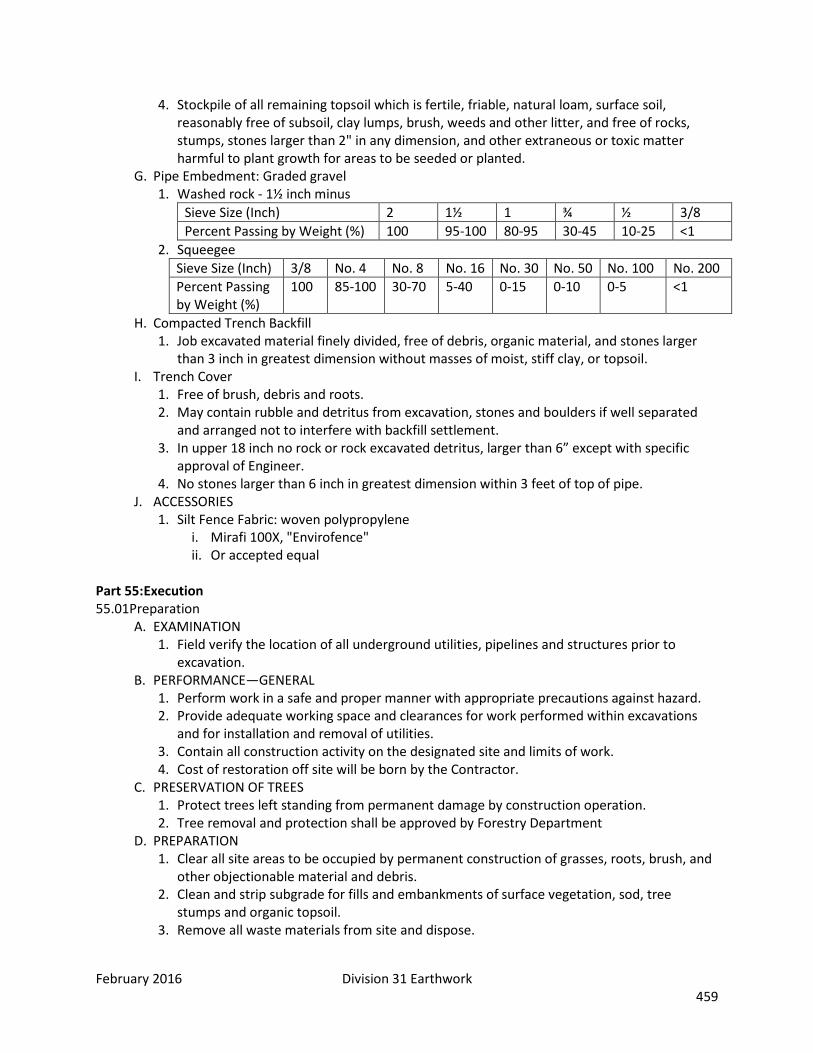
February 2016 Division 31 Earthwork 459
4. Stockpile of all remaining topsoil which is fertile, friable, natural loam, surface soil, reasonably free of subsoil, clay lumps, brush, weeds and other litter, and free of rocks, stumps, stones larger than 2" in any dimension, and other extraneous or toxic matter harmful to plant growth for areas to be seeded or planted.
G. Pipe Embedment: Graded gravel 1. Washed rock - 1½ inch minus
Sieve Size (Inch) 2 1½ 1 ¾ ½ 3/8 Percent Passing by Weight (%) 100 95-100 80-95 30-45 10-25 <1
2. Squeegee Sieve Size (Inch) 3/8 No. 4 No. 8 No. 16 No. 30 No. 50 No. 100 No. 200 Percent Passing by Weight (%)
100 85-100 30-70 5-40 0-15 0-10 0-5 <1
H. Compacted Trench Backfill 1. Job excavated material finely divided, free of debris, organic material, and stones larger
than 3 inch in greatest dimension without masses of moist, stiff clay, or topsoil. I. Trench Cover
1. Free of brush, debris and roots. 2. May contain rubble and detritus from excavation, stones and boulders if well separated
and arranged not to interfere with backfill settlement. 3. In upper 18 inch no rock or rock excavated detritus, larger than 6” except with specific
approval of Engineer. 4. No stones larger than 6 inch in greatest dimension within 3 feet of top of pipe.
J. ACCESSORIES 1. Silt Fence Fabric: woven polypropylene
i. Mirafi 100X, "Envirofence" ii. Or accepted equal
Part 55: Execution 55.01 Preparation
A. EXAMINATION 1. Field verify the location of all underground utilities, pipelines and structures prior to
excavation. B. PERFORMANCE—GENERAL
1. Perform work in a safe and proper manner with appropriate precautions against hazard. 2. Provide adequate working space and clearances for work performed within excavations
and for installation and removal of utilities. 3. Contain all construction activity on the designated site and limits of work. 4. Cost of restoration off site will be born by the Contractor.
C. PRESERVATION OF TREES 1. Protect trees left standing from permanent damage by construction operation. 2. Tree removal and protection shall be approved by Forestry Department
D. PREPARATION 1. Clear all site areas to be occupied by permanent construction of grasses, roots, brush, and
other objectionable material and debris. 2. Clean and strip subgrade for fills and embankments of surface vegetation, sod, tree
stumps and organic topsoil. 3. Remove all waste materials from site and dispose.

February 2016 Division 31 Earthwork 460
4. Remove debris, all trees, underbrush, stumps, roots and other combustible materials from site daily and dispose of off-site; on-site burning is not permitted.
55.02 Installation A. TOPSOIL
1. Strip on-site material meeting the topsoil definition to a minimum depth of 4 inches for all areas receiving grading.
2. At the completion of work in each area, place and grade topsoil to maintain gradient is required. Roughen surface for erosion control.
B. DEWATERING 1. Provide and maintain adequate dewatering equipment (including power supply, if
necessary) to remove and dispose of surface and groundwater entering excavations, trenches, and other parts of the work.
2. Keep each excavation dry during subgrade preparation and continually thereafter until the structure to be built or the pipe to be installed is completed to the extent that no damage from hydrostatic pressure, flotation, or other cause will result.
3. Dewater excavations which extend to or below groundwater by lowering and keeping the groundwater level beneath such excavation at least 12 inches below the bottom of the excavation.
4. Divert surface water or otherwise prevent it from entering excavated areas or trenches to the extent practical without damaging adjacent property.
5. Maintain all drainage pipes, keep clean and free of sediment during construction and final cleanup.
6. Dewatering to surface waterways requires Colorado Department of Public Health and Environment dewatering permit. Obtain dewatering permit and comply with discharge requirements therein, if necessary.
C. SHEETING, SHORING AND BRACING 1. Provide proper and substantial sheeting, shoring, and bracing, in accordance with OSHA
Standards as required, to prevent caving or sliding, to protect workmen and the Work, and to protect existing structures and facilities
2. Design and build sheeting, shoring, and bracing to withstand all loads that might be caused by earth movement or pressure, and to be rigid, maintaining shape and position under all circumstances.
3. Do not pull trench sheeting before backfilling unless pipe strength is sufficient, to carry trench loads based on trench width to the back of sheeting.
4. Do not brace sheeting left in place against the pipe, but support it in a manner that precludes concentrated loads or horizontal thrusts on pipe.
5. Cross braces installed above the pipe to support sheeting may be removed after pipe embedment is completed.
D. TRENCH STABILIZATION 1. Thoroughly compact and consolidate subgrade for concrete structures, precast structures,
and utility trench bottoms so they remain firm, dense and intact during required construction activities.
2. Remove all mud and muck during excavation. 3. Reinforce subgrade with crushed rock or gravel if they become mucky during construction
activities. 4. Finished elevation of stabilized subgrade are to be at or below subgrade elevations. 5. Allow no more than ½ inch depth of mud or muck to remain on trench bottoms when pipe
bedding material is placed thereon
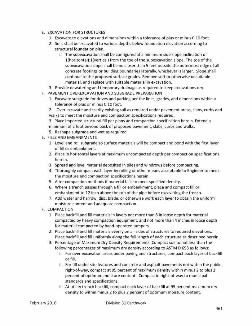
February 2016 Division 31 Earthwork 461
E. EXCAVATION FOR STRUCTURES 1. Excavate to elevations and dimensions within a tolerance of plus or minus 0.10 foot. 2. Soils shall be excavated to various depths below foundation elevation according to
structural foundation plan. i. The subexcavation shall be configured at a minimum side slope inclination of
1(horizontal):1(vertical) from the toe of the subexcavation slope. The toe of the subexcavation slope shall be no closer than 5 feet outside the outermost edge of all concrete footings or building boundaries laterally, whichever is larger. Slope shall continue to the proposed surface grades. Remove soft or otherwise unsuitable material, and replace with suitable material in excavation.
3. Provide dewatering and temporary drainage as required to keep excavations dry. F. PAVEMENT OVEREXCAVATION AND SUBGRADE PREPARATION
1. Excavate subgrade for drives and parking per the lines, grades, and dimensions within a tolerance of plus or minus 0.10 foot.
2. Over excavate and scarify existing soil as required under pavement areas, slabs, curbs and walks to meet the moisture and compaction specifications required. 3. Place imported structural fill per plans and compaction specification herein. Extend a minimum of 2 foot beyond back of proposed pavement, slabs, curbs and walks. 5. Reshape subgrade and wet as required
E. FILLS AND EMBANKMENTS 1. Level and roll subgrade so surface materials will be compact and bond with the first layer
of fill or embankment. 2. Place in horizontal layers at maximum uncompacted depth per compaction specifications
herein. 3. Spread and level material deposited in piles and windrows before compacting. 4. Thoroughly compact each layer by rolling or other means acceptable to Engineer to meet
the moisture and compaction specifications herein. 5. Alter compaction methods if material fails to meet specified density. 6. Where a trench passes through a fill or embankment, place and compact fill or
embankment to 12 inch above the top of the pipe before excavating the trench. 7. Add water and harrow, disc, blade, or otherwise work each layer to obtain the uniform
moisture content and adequate compaction. F. COMPACTION
1. Place backfill and fill materials in layers not more than 8 in loose depth for material compacted by heavy compaction equipment, and not more than 4 inches in loose depth for material compacted by hand-operated tampers.
2. Place backfill and fill materials evenly on all sides of structures to required elevations. Place backfill and fill uniformly along the full length of each structure as described herein.
3. Percentage of Maximum Dry Density Requirements: Compact soil to not less than the following percentages of maximum dry density according to ASTM D 698 as follows:
i. For over excavation areas under paving and structures, compact each layer of backfill or fill.
ii. For fill under site features and concrete and asphalt pavements not within the public right-of-way, compact at 95 percent of maximum density within minus 2 to plus 2 percent of optimum moisture content. Compact in right-of-way to municipal standards and specifications.
iii. At utility trench backfill, compact each layer of backfill at 95 percent maximum dry density to within minus 2 to plus 2 percent of optimum moisture content.

February 2016 Division 31 Earthwork 462
iv. For fill under lawn or unpaved areas, scarify and compact the top 6 inches below subgrade and each layer of backfill or fill material to 90 percent maximum dry density to within minus 2 to plus 2 percent of optimum moisture content.
v. Do not deposit or compact tamped or otherwise mechanically compacted backfill if frozen or if in water.
vi. Take particular care to compact backfill which will be beneath slabs, pipes, drives, roads, parking areas, curb, gutters, or other surface construction.
G. BORROW OR SPOIL AREA 1. Obtain suitable material required to complete fill and embankments from approved offsite
borrow area. 2. The location, size, shape, depth, drainage, and surfacing of borrow or spoil pits shall be
acceptable to Owner of borrow area. 3. Make all areas regular in shape with graded and surfaced side and bottom slopes when
completed. 4. Cut side slopes not steeper than 1:1 and uniform for the entire length of any 1 side 5. Final grade disturbed areas of borrow to uniform slope, 4:1 slope or flatter. 6. Use material free of debris and deleterious material.
H. BLASTING 1. Blasting or other use of explosives is not permitted.
I. TRENCH EXCAVATION 1. Establish alignment and grade or elevation from offset stakes. 2. Excavate trenches so pipes can be laid straight at uniform grade without dips or bumps,
between the terminal elevations. 3. Comply with pipe specification sections regarding vertical and horizontal alignment and
max joint deflection. 4. Excavate trenches to provide a minimum depth of backfill cover over the top of pipe as
follows. Coordinate depth of cover with utility owners. Increase depth as required by utility owner and at crossings.
i. 1.5 feet for drainage piping ii. 2.5 feet for gas piping iii. 3.0 feet in paved or graded streets where surface grades are fixed iv. 5.0 feet for sanitary sewer and water piping v. 2.5 feet for electric conduit vi. Increase depth as required at vertical curves and for clearance beneath existing
pipes, conduits, drains, drainage structures, or other obstructions encountered at normal pipe grades.
5. Measure pipe cover depth vertically from top of pipe to finished ground or surface elevation.
6. Do not open more trench in advance of pipe laying than is necessary to expedite the work; not more than 200 feet.
7. REQUIRED, Excavate trenches by open cut from the surface. 8. Limiting trench widths:
i. Excavate to a width which will provide adequate working space and pipe clearances for proper pipe installation, jointing, embedment
ii. If needed to reduce earth loads to prevent sliding, cut banks back on slopes which extend not lower than 1 foot above the top of the pipe
iii. Stipulated minimum clearances are minimum clear distances, not minimum average distances
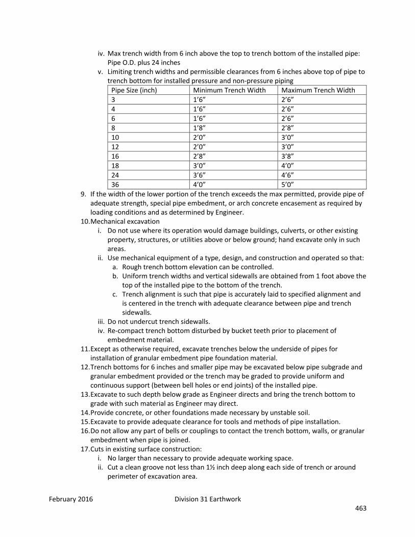
February 2016 Division 31 Earthwork 463
iv. Max trench width from 6 inch above the top to trench bottom of the installed pipe: Pipe O.D. plus 24 inches
v. Limiting trench widths and permissible clearances from 6 inches above top of pipe to trench bottom for installed pressure and non-pressure piping
Pipe Size (inch) Minimum Trench Width Maximum Trench Width 3 1’6” 2’6” 4 1’6” 2’6” 6 1’6” 2’6” 8 1’8” 2’8” 10 2’0” 3’0” 12 2’0” 3’0” 16 2’8” 3’8” 18 3’0” 4’0” 24 3’6” 4’6” 36 4’0” 5’0”
9. If the width of the lower portion of the trench exceeds the max permitted, provide pipe of adequate strength, special pipe embedment, or arch concrete encasement as required by loading conditions and as determined by Engineer.
10. Mechanical excavation i. Do not use where its operation would damage buildings, culverts, or other existing
property, structures, or utilities above or below ground; hand excavate only in such areas.
ii. Use mechanical equipment of a type, design, and construction and operated so that: a. Rough trench bottom elevation can be controlled. b. Uniform trench widths and vertical sidewalls are obtained from 1 foot above the
top of the installed pipe to the bottom of the trench. c. Trench alignment is such that pipe is accurately laid to specified alignment and
is centered in the trench with adequate clearance between pipe and trench sidewalls.
iii. Do not undercut trench sidewalls. iv. Re-compact trench bottom disturbed by bucket teeth prior to placement of
embedment material. 11. Except as otherwise required, excavate trenches below the underside of pipes for
installation of granular embedment pipe foundation material. 12. Trench bottoms for 6 inches and smaller pipe may be excavated below pipe subgrade and
granular embedment provided or the trench may be graded to provide uniform and continuous support (between bell holes or end joints) of the installed pipe.
13. Excavate to such depth below grade as Engineer directs and bring the trench bottom to grade with such material as Engineer may direct.
14. Provide concrete, or other foundations made necessary by unstable soil. 15. Excavate to provide adequate clearance for tools and methods of pipe installation. 16. Do not allow any part of bells or couplings to contact the trench bottom, walls, or granular
embedment when pipe is joined. 17. Cuts in existing surface construction:
i. No larger than necessary to provide adequate working space. ii. Cut a clean groove not less than 1½ inch deep along each side of trench or around
perimeter of excavation area.
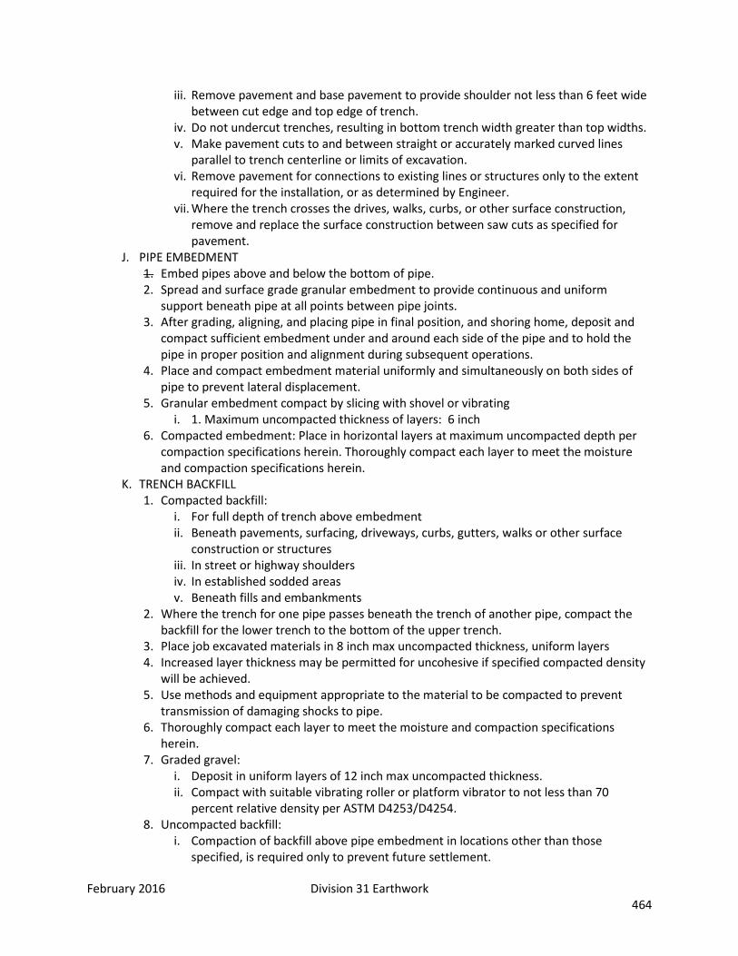
February 2016 Division 31 Earthwork 464
iii. Remove pavement and base pavement to provide shoulder not less than 6 feet wide between cut edge and top edge of trench.
iv. Do not undercut trenches, resulting in bottom trench width greater than top widths. v. Make pavement cuts to and between straight or accurately marked curved lines
parallel to trench centerline or limits of excavation. vi. Remove pavement for connections to existing lines or structures only to the extent
required for the installation, or as determined by Engineer. vii. Where the trench crosses the drives, walks, curbs, or other surface construction,
remove and replace the surface construction between saw cuts as specified for pavement.
J. PIPE EMBEDMENT 1. Embed pipes above and below the bottom of pipe. 2. Spread and surface grade granular embedment to provide continuous and uniform
support beneath pipe at all points between pipe joints. 3. After grading, aligning, and placing pipe in final position, and shoring home, deposit and
compact sufficient embedment under and around each side of the pipe and to hold the pipe in proper position and alignment during subsequent operations.
4. Place and compact embedment material uniformly and simultaneously on both sides of pipe to prevent lateral displacement.
5. Granular embedment compact by slicing with shovel or vibrating i. 1. Maximum uncompacted thickness of layers: 6 inch
6. Compacted embedment: Place in horizontal layers at maximum uncompacted depth per compaction specifications herein. Thoroughly compact each layer to meet the moisture and compaction specifications herein.
K. TRENCH BACKFILL 1. Compacted backfill:
i. For full depth of trench above embedment ii. Beneath pavements, surfacing, driveways, curbs, gutters, walks or other surface
construction or structures iii. In street or highway shoulders iv. In established sodded areas v. Beneath fills and embankments
2. Where the trench for one pipe passes beneath the trench of another pipe, compact the backfill for the lower trench to the bottom of the upper trench.
3. Place job excavated materials in 8 inch max uncompacted thickness, uniform layers 4. Increased layer thickness may be permitted for uncohesive if specified compacted density
will be achieved. 5. Use methods and equipment appropriate to the material to be compacted to prevent
transmission of damaging shocks to pipe. 6. Thoroughly compact each layer to meet the moisture and compaction specifications
herein. 7. Graded gravel:
i. Deposit in uniform layers of 12 inch max uncompacted thickness. ii. Compact with suitable vibrating roller or platform vibrator to not less than 70
percent relative density per ASTM D4253/D4254. 8. Uncompacted backfill:
i. Compaction of backfill above pipe embedment in locations other than those specified, is required only to prevent future settlement.

February 2016 Division 31 Earthwork 465
ii. May be placed by any method acceptable to Engineer which will not impose excessive concentrated or unbalanced loads, shock, or impact on, and will not result in displacement of installed pipe.
iii. Do not drop compact masses of stiff clay or other consolidated material more than 5 feet into trench unless cushioned by 2 feet minimum of loose backfill above pipe embedment.
9. Finish the top portion of backfill with at least 4 inches of topsoil corresponding to, or better than, that underlying adjoining turf areas.
L. DRAINAGE MAINTENANCE 1. Do not backfill trenches across roadways, drives, walks or other traffic ways adjacent to
drainage ditches or water courses prior to backfilling the trench on the upstream side of the traffic way to prevent impounding water after pipe is laid.
2. Backfill so that water does not accumulate in unfilled or partially filled trenches. 3. Remove materials deposited in roadway ditches or other water courses crossed by the
trench line immediately after backfilling is completed and restore ditches and water courses to original section, grade, and contours.
4. Do not obstruct surface drainage any longer than necessary. 5. Provide and maintain temporary bridges and other structures across unfilled trenches as
required to maintain traffic. M. PROTECTION OF TRENCH BACKFILL
1. Where trenches are constructed in ditches or other water courses, protect backfill from erosion.
2. Install ditch checks where the ditch grade exceeds 1 percent. i. Minimum depth: 2 feet below the original ditch or water course bottom for the full
bottom width ii. Minimum width: 18 inches into the side slopes iii. Minimum thickness: 12 inches
N. DISPOSAL OF EXCESS EXCAVATED MATERIALS 1. Use excess excavated materials in fills and embankments. 2. May dispose of up to 200 cubic yards of suitable excess excavated materials from onsite or
offsite at locations on the site directed by Owner. 3. Remove debris, junk, broken concrete, broken asphalt, rock, stones, stumps, logs, roots,
and other unsuitable material from the site and dispose of it. 4. Distribute excess earth from excavations located in unimproved property directly over the
pipe trench and within the pipeline right-of-way to a max depth of 6 inch above the original ground surface elevation at and across the trench and sloping uniformly each way
i. Carefully finish material thus wasted with a drag, blade machine, or other suitable tool to a smooth, uniform surface without obstructing drainage at any point.
ii. Do not waste excess excavated material in the above manner where the trench lines crosses or is within a railroad, public road, or highway right-of-way.
O. FINAL GRADING 1. After completion of all other outside work and after backfilling is completed and settled,
bring to grade at the elevations. 2. Graders and other power equipment may be used for final grading and slope dressing if
the result is uniform and equivalent to hand work. 3. Grade all surfaces for effective drainage, provide a 2 percent minimum slope except as
otherwise required. 4. Grade and surface to maintain gradient.
February 2016 Division 31 Earthwork 466
P. SLOPE AND CHANNEL STABILIZATION 1. Cover channel banks, slopes or channel thalweg (water flow-line at deepest part of the
channel) with erosion control fabric mat where grade is 3H to 1V or greater. 2. Lay fabric smoothly on surface, bury top end of each section in 6-inch deep excavated
topsoil trench. Provide 6 inch overlap minimum of adjacent rolls. Backfill trench and rake smooth, level with adjacent soil.
3. Secure outside edges and overlaps at 48 inch intervals with 4-inch to 6-inch U-shaped type pins or wooden stakes depending on ground condition.
4. Lightly dress slopes with topsoil to ensure close contact between fabric and soil. 5. At sides of ditches, lay fabric laps in direction of water flow. Lap ends and edges minimum
6 inches. 6. Maintain integrity of erosion control fabric throughout installation.
Q. SETTLEMENT 1. Warranty for settlement of all fills, embankments, and backfills is stipulated in the General
Conditions from final completion of Contract under which Work is performed. 2. Repair or replace within 30 days after notice by Engineer or Owner.
R. FIELD QUALITY CONTROL 1. Provide under provisions of General Conditions and Division 1 Specifications. 2. Coordinate testing with Owner. Owner will provide all field testing to determine
compliance of in-place and backfill materials and compaction in accordance with the specifications, and to verify design bearing capacities.
3. Fills and Embankment i. Two moisture-density relationship tests, ASTM D698, on each type of fill material ii. One in-place compaction test for each 5,000 square feet every 1.5 feet of vertical lift
of material placed iii. Additional in-place compaction tests at the discretion of the Owner
4. Pipe Embedment and Backfill i. Two moisture-density relationship tests, ASTM D698, or two relative density tests,
ASTM D4253/D4254, as appropriate for each type of embedment on backfill material proposed, except granular embedment material.
ii. One in-place compaction test every 200 lineal feet of trench in the compacted embedment zone and at every 1.5 feet of vertical lift of backfill materials, ASTM D2922/D3017.
iii. One in-place compaction test near top of trench for trench depth of 2 feet or less, ASTM D2922/D3017.
iv. Additional in-place compaction tests at the discretion of the Owner. 5. Pavement and Structural Subgrades
i. At a minimum, two moisture-density relationship tests, ASTM D698, or two relative density tests, ASTM D4253/D4254, as appropriate and adequate for each type backfill material proposed.
ii. Perform tests for each footing, concrete site feature, and drainage structure subgrade. Perform tests at every 50 linear feet of subgrade of foundation walls, retaining walls, and curbing, pans, drainage features, walks, etc. (or portions thereof). Perform tests every 2,000 square feet required of building slab area, exterior slabs and pavement/flatwork areas (with no less that 3 tests). Test at subgrade and at every vertical lift of backfill materials placed.
iii. Additional in-place compaction tests at the discretion of the Owner S. BUILDING PAD RESHAPING

February 2016 Division 31 Earthwork 467
1. Building Pad Approval i. Overlot grading has taken place prior to the award of this Contract. Responsible for
discing and reshaping the building pad area for those locations which have been damaged by freezing temperatures, frost, rain, accumulated water or construction activities.
ii. Certify subgrade elevations and compaction for the building pad. iii. If Architect/Engineer determines that unsatisfactory soil is present, continue
excavation and replace with compacted backfill or fill material. iv. Proof roll subgrade with heavy pneumatic-tired equipment to identify soft pockets
and areas of excess yielding. Do not proof roll wet or saturated subgrades. 1.04 Cleaning and Protection
END OF SECTION 31 00 00
SECTION 31 10 00 – SITE CLEARING Part 1: General 1.01 Summary
A. Section Includes, but is not limited to: 1. Removal of surface debris. 2. Removal of paving and curbs. 3. Removal of trees, shrubs, and other plant life.
1.02 Related Sections 1.03 Definitions 1.04 Submittals Required 1.05 Quality Assurance
A. Coordinate clearing work with Utility Companies. Comply with their requirements. 1.06 Scheduling 1.07 Delivery, Storage, and Handling
A. ENVIRONMENTAL REQUIREMENTS 1. Observe environmental precautions based on conditions. 2. Conform to applicable ordinances and codes for dust and erosion control, disposal of
debris, use of herbicides, and other environmental requirements. 1.08 Regulatory Requirements Part 2: Products 2.01 Manufacturers 2.02 Products
A. Herbicide: 1. “Round Up” by Monsanto Agricultural Products
Part 3: Execution 3.01 Preparation
A. Verify that existing plant life designated to remain is tagged or identified. 3.02 Installation

February 2016 Division 31 Earthwork 468
3.03 Cleaning and Protection A. PROTECTION
1. Locate, identify, and protect from damage utilities that remain. 2. Protect existing trees, plant growth, and features. 3. Protect bench marks, and survey control joints from damage or displacement.
B. CLEARING 1. Clear areas required for access to site and execution of Work. 2. Clear undergrowth and deadwood, without disturbing subsoil. 3. Apply herbicide to remaining stumps and vegetation to inhibit growth.
C. REMOVAL 1. Remove trees and shrubs within marked areas. Remove stumps and root systems to depth
of 3 feet. 2. Remove debris, rock, and extracted plant life from site. 3. Remove paving and curbs as required to connect to existing. 4. Remove debris from site clearing operations from the site.
END OF SECTION 31 10 00
SECTION 31 23 00 – EXCAVATION AND FILL
Part 1: General 1.01 Summary
A. This section covers excavation and trenching, including drainage, preparation of subgrades, pipe bedding, backfilling, compacting, and finish grading for underground pipelines and appurtenances.
1.02 Related Sections 1.03 Definitions 1.04 Submittals Required 1.05 Quality Assurance
A. "CDOT" refers to Colorado Department of Transportation designations in their "Standard Specifications for Road and Bridge Construction." 1. When CDOT is referenced herein.
1.06 Scheduling A. Right-of-Way.
1. 1. In developed areas haul and stockpile excess material or erect suitable bulkheads to prevent deposition of excavated material where right-of-way or easements are not adequate to stockpile all excavated material without depositing it on private property.
B. Drainage and Groundwater. 1. Maintain excavations and trenches free from water during construction. 2. Remove water encountered in the trench to the extent necessary to provide a firm
subgrade, to permit joints to be made in the dry, and to prevent the entrance of water into the pipeline.
3. Divert surface runoff and use sumps, gravel blankets, well points, drain lines or other means necessary to accomplish the above.

February 2016 Division 31 Earthwork 469
4. Maintain the excavation or trench free from water until the structure, or pipe to be installed therein, is completed to the extent that no damage from hydrostatic pressure, flotation, or other cause will result.
5. Uncontaminated groundwater shall be prevented from entering into previously constructed pipe. Groundwater contaminated by sanitary waste shall be discharged into the sanitary sewer.
6. The pipe under construction shall not be used for dewatering. C. Sequencing.
1. Perform pipeline installation within 50 linear feet of trench excavation. 2. Perform trench backfill within 50 linear feet of pipe installation. 3. Perform clean-up within 200 linear feet of trench excavation. 4. Where excavation is a hazard to automotive or pedestrian traffic, the amount of open
trench and the time duration of that opening is to be minimized. 5. Maintain access to private residence and businesses.
D. Underground Obstructions. 1. Locate and verify all underground utilities and obstructions. 2. Maintain, protect and support by shoring, bracing or other means existing utilities,
appurtenances and structures. 3. Take such protective measures as the utilities may direct where protection, alternations or
moving of the utilities is required. E. Weather.
1. Do not backfill or construct fills or embankments during freezing weather. 2. Do not place backfill, fill or embankment on frozen surfaces. 3. Do not place frozen materials, snow or ice in backfill, fill or embankments. 4. Do not deposit, tamp, roll or otherwise mechanically compact backfill in water.
1.07 Delivery, Storage, and Handling A. Storage.
1. Provide adequate and orderly storage of excavated material adjacent to Work. 2. Pile suitable material for backfilling in an orderly manner a sufficient distance from banks
or trench or excavation to avoid overloading and to prevent slides or cave-ins. 3. Do not stockpile excavated materials against existing structures, Work, or appurtenances. 4. Excess excavated material will not remain on job site for more than one (1) month.
1.08 Regulatory Requirements A. MAINTENANCE AND CORRECTION
1. Scarify surface, reshape, and compact to required density completed or partially completed areas of work disturbed by subsequent construction operations or by adverse weather.
2. Maintain and correct backfill, fill and embankment settlement and make necessary repairs to pavement structures, seeding and sodding which may be damaged as a result of settlement for period of one (1) year after Substantial Completion and acceptance of the Work.
Part 2: Products 2.01 Manufacturers 2.02 Products
A. GENERAL

February 2016 Division 31 Earthwork 470
1. All material shall be free from frozen matter, stumps, roots, brush, other organic matter, cinders or other corrosive material, debris, broken asphalt and concrete, and any other material that is not suitable in the opinion of the Town.
2. If job excavated material is not sufficient or suitable, suitable material shall be imported. All imported material shall have a liquid limit not greater than 30 and a plasticity index not greater than 6.
B. STABILIZATION MATERIAL 1. Top 6 inches of pipe subgrade - If the existing soil in the trench bottom is judged to be
unsuitable the top 6-inches of the pipe subgrade shall be removed and replaced with a stabilization material.
i. Stabilization material is crusher-run rock, conforming to ASTM D448, size #357. Size 2 ½" 2" 1" ½" #4 Percent Passing 100 95-100 35-70 10-30 0-5
2. Geotextile: CDOT, Section 712.08, Class A Table 712-2. 3. Subgrade below top 6 inches - Same as top 6 inches except that broken concrete and rock
may be included in sizes permitting compaction without discernible voids. i. Alternative materials for stabilization of sub-grade will be considered for use as
approved by the Town and Engineer. C. BEDDING MATERIALS
1. Definition: Materials placed from the subgrade to an elevation 12 inches above the top of pipe.
2. Granular material. i. Angular crushed rock, conforming to CDOT #67.
Size 1" 3/4" 3/8" #4 #8 Percent Passing 100 90-100 20-55 0-10 0-5
ii. Or, well-graded angular crushed rock: 95% passing a one (1) inch sieve and not more than 5% passing a No. 4 sieve.
3. Concrete. i. Compressive strength: 4000 psi at 28 days minimum. ii. Class A concrete, reference Colorado Department of Transportation, Division of
Highways, State of Colorado "Standard Specifications for Road and Bridge Construction".
4. Barrier material. i. Soil Classification.
a. GC - clayey gravels, gravel-sand-clay mixtures. b. SC - clayey sands, sand-clay mixtures. c. CL - inorganic clays of low to medium plasticity, gravelly clays, sandy clays, silty
clays, clean clays. d. Material shall not be lumpy or hard but shall be finely divided, suitable, and free
from stones. 5. Bedding material for service lines less than four (4) inches in diameter shall be sands or
silts and clays meeting the Unified Soil Classification types ML or CL. Material shall not be lumpy or hard but shall be finely divided, suitable, and free from stones greater than ½ inch in its largest dimension.
D. TRENCH BACKFILL MATERIAL 1. Trench backfill material shall be placed from a point 12-inches above the pipe to 6-inches
below the ground surface, to bottom of topsoil layer, or to the bottom of the pavement subgrade, whichever is applicable.

February 2016 Division 31 Earthwork 471
2. Trench backfill material shall be soil free from any rocks or stones which are larger than 6-inches, in any dimension.
i. Rocks or stones which are larger than 3-inches, in any dimension, shall not be placed within one foot of pavement subgrade, or within one foot of the finished surface of unpaved areas.
ii. Material shall not be lumpy or hard but shall be finely divided. Part 3: Execution 3.01 Preparation
A. Topsoiling. Remove a minimum of 6 inches of topsoil and stockpile topsoil away from areas to be disturbed by construction. Keep topsoil segregated from non-organic excavation materials and debris.
3.02 Installation A. TRENCHING
1. Avoid removal of obstructions. 2. Do not use mechanical equipment in locations where its operation would cause damage to
trees, buildings, culverts, or other property, utilities, or structures above or below ground. In all such locations, hand excavating methods shall be used.
3. Use mechanical equipment so designed and operated that the rough trench excavation bottom elevation can be controlled with uniform trench widths and vertical sidewalls from an elevation one foot above the top of the installed pipe to the bottom of the trench, and trench alignment sufficiently accurate to permit pipe to be aligned properly between the pipe and sidewalls of the trench. Do not undercut the trench sidewall to obtain clearance.
4. Excavation in rock. i. Over excavate a minimum of six inches below the bottom of the pipe. ii. Backfill with Granular Material.
5. Preparation of Trench Bottom. i. Grade trench bottoms uniformly to provide clearance for each section of pipe. ii. Remove loose materials, water and foreign objects. iii. Provide firm subgrade suitable for application of bedding material. iv. Wherever unstable material is encountered in the bottom of the trench, over-
excavate such material to a depth suitable for construction of a stable subgrade. Backfill overdepth with Stabilization Material and compact. A layer of geotextile fabric shall be placed between the stabilization material and the bedding material.
6. Stockpiling Excavated Materials. i. Pile suitable material for backfilling in an orderly manner a sufficient distance from
banks of the trench to avoid overloading and to prevent slides or cave-ins. ii. Remove and dispose of excess excavated materials not suitable or not required for
backfilling. iii. Do not stockpile excavated material against existing structures or appurtenances. iv. Excess excavated material will not remain on job site for more than one (1) month.
7. Limiting Trench Widths. i. Trenches shall be excavated to a width necessary to provide a 12-inch minimum
working space between the pipe and the trench walls for proper pipe installation, joining, and bedding.
ii. The maximum trench width at an elevation 12 inches above the top of the installed pipe, shall be 2 barrel diameters of the pipe or 32 inches whichever is greater.
February 2016 Division 31 Earthwork 472
a. If the width of the trench, 12 inches above the top of the installed pipe, exceeds the maximum allowable trench width, a higher strength pipe or special pipe bedding shall be provided, as required by soil loading conditions and as determined by the Town.
B. PIPE BEDDING 1. A. Bedding classes: Provide higher class bedding where unexpected trench conditions are
encountered. 2. B. Placement and Compaction.
i. Distribute and grade bedding material to provide uniform and continuous support beneath the pipe at all points between bells and pipe joints.
ii. Deposit bedding material and compact uniformly and simultaneously on each side of the pipe to prevent lateral displacement.
iii. Compact granular bedding material by vibrating, slicing with a shovel, or bent tee-bar.
3. Ground Water Barriers. i. To impede passage of water through bedding material, construct a ground water
barrier the full trench width, approximately 4 feet long, and from the bottom of all Granular Material to top of Granular Material.
ii. Space: a. Approximately 10 feet downstream of each manhole for sanitary sewers and
storm drains. b. Every 400 feet on water lines and force main. c. Place a ground water barrier 20 feet downstream of the edge of all drainage
ways, streams and water courses. 4. Over Depth Excavation.
i. Restore over excavated subgrades to proper elevation with Stabilization Material or Granular Material.
C. BACKFILLING AND COMPACTION 1. Backfill trench promptly after completion of pipe bedding. 2. Deposit backfill material in uniform layers not exceeding eight inches in uncompacted
thickness. Increased layer thickness may be acceptable provided it is demonstrated that the specified compacted density will be obtained.
3. Use methods and equipment appropriate for the backfill material. Do not use equipment or methods that will transmit damaging shocks to the pipe.
i. Do not perform compaction by jetting or water settling. 4. Import material for trench backfill if compaction cannot be obtained with job excavated
material, when specifically required by these Contract Documents, or required by jurisdictional authorities.
5. Rock and bedrock encountered in the excavation shall be separated from other excavated material and disposed of.
6. Topsoiling - Replace topsoil after construction and grading to the depth of stripping over all areas disturbed by construction operations and which will not receive other surface treatment.
7. Obtaining a site for disposal of excavated rock and bedrock material, excess excavated materials, and material not suitable for backfilling is necessary. If excavated materials are disposed on private property, written permission shall be obtained from the property owner and a copy given to Town.
D. FIELD QUALITY
February 2016 Division 31 Earthwork 473
1. Field Compaction Control. i. Field tests will be conducted to determine compliance of compaction methods with
specified density in accordance with: a. ASTM D2922 (AASHTO T238) - Tests for Density of Soil and Soil - Aggregate In-
Place by Nuclear Methods, or b. ASTM D1556 (AASHTO T191) - Tests for Density of Soil In-Place by the Sand
Cone Method, or c. ASTM D2167 (AASHTO T205) - Tests for Density of Soil In-Place by Rubber-
Balloon Method. 2. Compaction shall be to the following minimum densities.
i. Subgrade under footings or foundations: 100% ii. Barrier material: 95% iii. Pipe bedding.
a. Compacted granular material: 80% (ASTM D4253, D4254) b. Barrier material: 95%
iv. Trench backfill. a. Within right of way and under areas of permanent surface improvements: 95% b. Under footings, foundations or structures: 95%. c. Seeded areas: 88%. d. All other locations: 95%. e. Do not compact topsoil.
v. Where granular materials are used in lieu of cohesive soils reduce the above percentages by 15% to arrive at the relative density and ASTM D4253 and D4254 shall apply.
3. Moisture Content. i. All compacted backfill shall be within 2% (+/-) of the optimum moisture content of
the soil as determined by ASTM D698. ii. Water shall be added to the material, or the material shall be harrowed, disced,
bladed, or otherwise worked to insure a uniform moisture content. E. COMPACTION TEST FAILURE
1. Recompact the material to the required state of compaction. In cases where there is a failure to achieve the required state of compaction, the Town may require that the backfill be removed and recompacted or replaced.
2. A hydrostatic retest shall be required on water lines after recompaction if the hydrostatic testing had been performed prior to recompaction.
i. Testing shall be performed between valves on both sides of area of recompaction. 3. C. A retest of wastewater lines shall be required after recompaction if the testing has been
performed prior to recompaction. i. Testing shall be performed between manholes on both sides of area of
recompaction. 3.03 Cleaning and Protection
END OF SECTION 31 23 00
February 2016 Division 32 Exterior Improvements 474
DIVISION 32: Exterior Improvements
SECTION 32 05 00 – COMMON WORK RESULTS OF EXTERIOR IMPROVEMENTS Part 1: General 1.01 Summary 1.02 Related Sections 1.03 Definitions 1.04 Submittals Required 1.05 Quality Assurance 1.06 Scheduling 1.07 Delivery, Storage, and Handling 1.08 Regulatory Requirements Part 2: Products 2.01 Manufacturers 2.02 Products
A. Source materials and products regionally whenever possible. Submit documentation of manufacturing locations and origins of materials for products manufactured and/or sourced from within 500 miles of the building site.
B. Use recycled and/or rapidly renewable materials whenever possible. Submit invoices and listings of recycled and/or rapidly renewable materials are used. 1. Indicate recycled content; indicate percentage of pre-consumer and post-consumer
recycled content per unit of product. 2. Select products with the highest recycled or rapidly renewable content that is readily
available C. Use salvaged and recovered products where feasible. Submit documentation showing the
origins of any salvaged products.
Part 3: Execution 3.01 Preparation 3.02 Installation
END OF SECTION 32 05 00
SECTION 32 10 00 – PAVING, SIDEWALKS, AND CURBING Part 1: General 1.01 Summary
A. This section includes: 1. Paving requirements 2. Construction of curbs, curbs with gutters, cross-pan sections, and sidewalks.
February 2016 Division 32 Exterior Improvements 475
3. Pavement markings B. Refer to City of Fort Collins Streets Department specifications for paving. C. Snowplow access required to all paved areas, including sidewalks. D. Curb Configuration: Vertical with full cut at drives and ramps. Invert curbs preferred. Roll curb
on a case by case basis. E. Drainage shall not cross major pedestrian paths. F. Specify the least amount of asphaltic concrete paving as possible. Utilize light colored/high albedo
materials with a high Solar Reflectance Index (SRI) instead of asphalt when feasible. G. Where feasible, use rubberized asphalt. Preference shall be given to mixes using wet or dry
crumb rubber materials. Crumb rubber shall be 100% post-consumer recycled tires. H. Where feasible, incorporate crushed concrete or blast furnace slag complying with ASTM D692;
recycled porcelain or other non-traditional aggregate material complying with ASTM D6155; or onsite demolition debris. Reduce use of Portland cement by using less cement or substituting a percentage of material with fly ash, slag cement or other recycled material. Provide appropriate documentation.
I. Consider porous pavement systems such as precast concrete pavers, monolithic concrete porous pavement, or recycled plastic pavers to reduce site impervious cover.
1.02 Related Sections 1.03 Definitions 1.04 Submittals Required
A. Product Data B. Samples
1.05 Quality Assurance A. QUALIFICATIONS
1. Installer (Pavement Marking) MUST BE regularly engaged in this type of work and with proper equipment for striping a project of this size.
B. STANDARDS (Pavement Marking) 1. Comply with the Larimer County Urban Area Street Standards, latest edition. 2. Comply with the Manual for Uniform Traffic Control Devices (MUTCD), latest edition.
C. WARRANTY 1. Bituminous (Asphalt) Pavement: Two-year labor and material warranty covering creeping,
shoring, cracking, settling, and ponding. 1.06 Scheduling 1.07 Delivery, Storage, and Handling 1.08 Regulatory Requirements Part 2: Products 2.01 Manufacturers 2.02 Products
A. Concrete paving required at the following locations: 1. Trash pick-up areas 2. Loading dock areas 3. Entrance walks
B. Concrete paving preferred at the following locations, where budget allows: 1. Bus Stop / Terminals 2. Parking areas 3. Dumpster pads 4. Service vehicle parking areas

February 2016 Division 32 Exterior Improvements 476
C. Asphaltic pavement preferred elsewhere. Thickness to match use D. Walks: walks that are driven on should be a minimum 6” deep and 8’ wide where applicable. E. Drain Pans: 4’ drain pans are recommended. Concrete drain pans within asphalt pavement are
preferred. F. Wheelstops:
1. May be used depending on location. 2. Permanent curbs preferred
G. Pavement Marking Materials: 1. Paint markings shall not fade, crack, flake, or peel within the warranty period. 2. Yellow color, or white markings/red curb for fire lanes, meeting requirements of Section
708.05, "Pavement Marking Paint" of the Standard Specifications for Road and Bridge Construction, 1986, Colorado Department of Highways.
Part 3: Execution 3.01 Preparation 3.02 Installation
A. EXECUTION 1. Herbicide:
i. In instances where base is replaced, herbicide is required 2. Asphalt Reinforcing Mesh: 2" minimum overlay. 3. Asphalt Edge Detail (Mandatory): Curb or 12"-wide reinforced concrete to depth of base
course. 4. Concrete Reinforcing: Maintain welded wire fabric between center and bottom 1/4 of slab.
Fiber mesh may be used when called for. 5. Concrete Finish: Medium broom texture perpendicular to main traffic flow.
B. FIELD QUALITY CONTROL 1. Notify City of Fort Collins Project Manager at least 24 hours in advance of the following:
i. Start of excavation, backfilling and compacting operations. ii. Staking of grades/elevations. iii. Subgrade placement. iv. Base course placement. v. Prime coat. vi. Wearing surface placement.
C. SUBGRADE 1. Scarify to a depth of 6 inches and compact. 2. Do not work on subgrade while ground is frozen or muddy.
D. FORMING 1. Forms shall be of full depth and shall be of such design as to permit secure fastening. 2. Face boards if used, shall be so constructed and shaped that their lower edge conforms to
lines and radii of structures. 3. Use flexible or curved forms of proper radius for curves of 100 foot radius or less.
E. JOINTS 1. Traverse joints shall be located at intervals of 10 feet in curbs, gutters, and crosspans. For
sidewalks tooled joints shall be at 5 feet. Joints shall be continuous through all three elements. Joints shall be a minimum of 1/4 thickness of the concrete. Set joints at right angles to face, top, and flow line.
2. Expansion joint material shall be installed between new structures and existing concrete, concrete pans, around fire hydrants, poles, inlets, other fixed objects, and between the
February 2016 Division 32 Exterior Improvements 477
ends of sidewalk slabs and curbs. Expansion joint material shall be vertical and with the top edge flush with the finished surface. The joint shall be edged with a suitable edging tool.
3. Sealing Joints: i. Apply cold poured silicone sealant in accordance with manufacturer's instructions.
Backer rod is not required. F. CONCRETE REPLACEMENT
1. Remove, dispose of and restore to original or better condition concrete drives, curbs, gutters, sidewalks, and similar structures that get damaged during construction.
i. Remove concrete to neatly sawed edges or to existing smooth joint lines. a. Saw concrete to a minimum depth of 2 inches. b. If saw cut would fall within 3 feet of construction joint, cold joint, expansion
joint, or edge, remove concrete to the joint. ii. Base course - construct in accordance with the Standard Specifications.
a. Restore to same thickness as existing, but in no case less than 3 inches. 2. Restore to existing alignment, dimensions and grades, or new alignment, dimensions and
grades. 3. Provide for a 30 diameter lap if existing concrete that is removed contains reinforcing
steel. New steel shall be of same diameter and of equal or better quality. 4. Restore all surface improvements to the same thickness as existing, but in no case less
than the following: i. Driveway - 6 inches. ii. Gutter - 6 inches measured at flowline. iii. Sidewalk – 5 inches.
5. Tool outside edges of sections and joints with a 1/4 inch radius edging tool. G. MANHOLE FRAMES AND VALVE BOXES
1. Prior to placing concrete adjust manhole frames and water valve boxes to final grade. Leave 1/4 inch below grade in areas of snowplowing.
2. Immediately remove foreign matter which is introduced into manholes, water valve boxes to provide free access to the facilities.
3. Valve boxes and manhole rings shall be straight and properly aligned. i. Valve boxes shall be inspected by placing a valve key on the operating nut to assure a
proper alignment. H. FINISHING
1. Trowel and brush face surface of curb and gutter. 2. Immediately after float finishing sidewalks and cross pans, slightly roughen the concrete
surface by brooming in the direction perpendicular to the main traffic flow. 3. Round back edge of curbs, lip of gutter adjacent to pavement, and edges adjacent to joints
with edger of 1/4 in. radius. 4. Fill honeycombed back formed areas with mortar. Replace concrete sections when
honeycomb is exposed to view. I. FIELD QUALITY CONTROL
1. Compact to accepted densities submitted with the mix design. The following are minimum densities in accordance with ASTM D698:
i. Subgrade: 95% ii. Base Course: 95%
2. The work shall be in accordance with the following tolerances:
February 2016 Division 32 Exterior Improvements 478
i. When checked with a ten foot (10’) straightedge, grade shall not deviate by more than one-quarter inch (1/4”) and alignment shall not vary by more than one-half inch (1/2”). Final elevation shall not depart from plan elevation by more than one-half inch (1/2”).
3.03 Cleaning and Protection
END OF SECTION 32 10 00
SECTION 32 80 00 – IRRIGATION
Part 1: General 1.01 Summary
A. Section Includes: 1. Landscape irrigation systems. 2. Irrigation controllers and accessories.
B. Automatic pond aeration systems may be required and will be considered on a site by site basis.
1.02 Related Sections 1.03 Definitions 1.04 Submittals Required 1.05 Quality Assurance
A. Owner inspections to be scheduled by contractor- required for approval/acceptance of system. B. Guarantee, Warranty and Replacement.
1. For a period of one year from commencement of the formal maintenance period, guarantee/warranty irrigation materials, equipment, and workmanship against defects. Fill and repair depressions. Restore landscape or structural features damaged by the settlement of irrigation trenches or excavations. Repair damage to the premises caused by a defective item. Make repairs within seven days of notification from the Owner’s Representative.
2. Contract documents govern replacements identically as with new work. Make replacements at no additional cost to the contract price.
3. Guarantee/warranty applies to originally installed materials and equipment and replacements made during the guarantee/warranty period.
C. Water flow and consumption rates: Provide irrigation system in accordance with approved water budget for landscape.
D. Installer Qualifications: Engage an experienced Installer with minimum 3 years experience with work similar in material, design, and extent to that indicated for this Project and certified as a Certified Irrigation Contractor (CIC) through a WaterSense labeled program.
E. Post-Installation Audit: Conduct an audit of the irrigation system [immediately after installation] [after one year of operation] [and three years thereafter] by a WaterSense Irrigation Partner.
1.06 Scheduling A. TESTING:
1. Pipelines jointed with rubber gaskets or threaded connections may be subjected to a pressure test at any time after partial completion of backfill. Pipelines jointed with solvent-welded PVC joints shall be allowed to cure at least 24 hours before testing.
February 2016 Division 32 Exterior Improvements 479
2. Subsections of mainline pipe may be tested independently, subject to the review of the Owner’s Representative.
3. All costs, including travel expenses for site visits by the Engineer, for any reinspection that may be required due to non-compliance with the Construction Documents shall be the sole responsibility of the Contractor.
4. Hydrostatic Pressure Test (Solvent Weld Mainline Pipe): i. Subject mainline pipe to a hydrostatic pressure equal to 140 PSI for two hours. Test
with mainline components installed. ii. Backfill to prevent pipe from moving under pressure. Expose couplings and fittings. iii. Expose all remote control valves their riser pipe and service tee fittings. iv. Leakage will be detected by visual inspection. Replace defective pipe, fitting, joint,
valve, or appurtenance. Repeat the test until the pipe passes test. v. Cement or caulking to seal leaks is prohibited.
5. Volumetric Leakage Test (Gasketed Mainline Pipe): i. Backfill to prevent pipe from moving under pressure. Expose couplings and fitting. ii. Expose all remote control valves their riser pipe and service tee fittings. iii. Purge all air from the pipeline before test. iv. Subject mainline pipe to 140 PSI for two hours. Maintain constant pressure. The
amount of additional water pumped in during the test shall not exceed 0.96 gallons per 100 joints of 3-inch diameter pipe and 1.28 gallons per 100 joints of 4-inch diameter pipe. Replace defective pipe, fitting, joint, valve, or appurtenance. Repeat the test until the pipe passes test.
v. Cement or caulking to seal leaks is prohibited. 6. Operational Test:
i. Activate each remote control valve in sequence from controller. The Owner’s Representative will visually observe operation, water application patterns, and leakage.
ii. Repeat test(s) until each lateral passes all tests. Repeat tests, replace components, and correct deficiencies at no additional cost to the Owner.
7. Central Control System Acceptance Test: i. Upon completion of construction, a System Acceptance Test must be passed. ii. Following construction completion and a Review by the Engineer, an evaluation
period will begin. After 30 days of continuous service without major system problems, the system will be accepted and the guarantee/warranty period will begin. If at any time during the 30-day evaluation period, a major system problem occurs, the source of the problem will be determined and corrected and the 30-day evaluation period will start again. Equipment will not be accepted until such time as the System Acceptance Test is passed.
iii. If successful completion of the System Acceptance Test is not attained within 90 days following commencement of the evaluation period, the Owner’s Representative has the option to request replacement of equipment, terminate the order, or portions thereof, or continue with the System Acceptance Test. These options will remain in effect until such time as a successful completion of the System Acceptance Test.
8. Control System Grounding: i. Test for proper grounding of control system per manufacturer's recommendations.
Test results must meet or exceed manufacturer's guidelines for acceptance. ii. Replace defective wire, grounding rod, or appurtenances. Repeat the test until the
manufacturer's guidelines are met.

February 2016 Division 32 Exterior Improvements 480
1.07 Delivery, Storage, and Handling 1.08 Regulatory Requirements
A. Work and materials shall be in accordance with the latest edition of the National Electric Code, the Uniform Plumbing Code as published by the Western Plumbing Officials Association, and applicable laws and regulations of the governing authorities.
Part 2: Products 2.01 Manufacturers 2.02 Products
A. SLEEVING: 1. Install separate sleeve beneath paved areas to route each run of irrigation pipe or wiring
bundle. 2. Sleeving material shall be PVC Class 200 pipe with solvent welded joints. 3. Sleeving diameter: equal to twice that of the pipe or wiring bundle.
B. PIPE AND FITTINGS: 1. Mainline Pipe and Fittings:
i. Use rigid, unplasticized polyvinyl chloride (PVC) ii. Use Class 200, SDR-21, rated at 200 PSI iii. Use rubber-gasketed pipe equipped with factory installed reinforced gaskets for
mainline pipe with a nominal diameter greater than or equal to 3-inches. iv. Use solvent weld pipe for mainline pipe with a nominal diameter less than 3-inches
or where a pipe connection occurs in a sleeve. 2. Lateral Pipe and Fittings:
i. Use rigid, unplasticized polyvinyl chloride (PVC) ii. Use Class 160, SDR-26, rated at 160 PSI.
3. Specialized Pipe and Fittings: i. Copper pipe: Use Type "K" rigid pipe conforming to ASTM Standard B88. Use Type
“M” soft tubing conforming to ASTM Standard B88. Use wrought copper or cast bronze fittings, soldered, flared mechanical, or threaded joint per installation details or local code. Use a 95-percent tin and 5-percent antimony solder.
ii. Low Density Polyethylene Hose: a. Use pipe specifically intended for use as a flexible swing joint. Inside diameter:
0.490+0.010 inch. Wall thickness: 0.100+0.010 inch. Color: Black. b. Use spiral barb fittings supplied by the same manufacturer as the hose.
iii. Use dielectric union wherever copper-based metal (copper, brass, bronze) is joined to iron-based metal (iron, galvanized steel, stainless steel).
iv. Assemblies calling for flanged connections shall utilize stainless steel studs and nuts and rubber gaskets.
v. Assemblies calling for threaded pipe connections shall utilize PVC Schedule 80 nipples and PVC Schedule 40 threaded fittings.
vi. Joint sealant: Use nonhardening, nontoxic pipe thread sealant formulated for use on threaded connections and approved by the pipe fitting and valve manufacturers. Where directed by valve manufacturers, use thread tape for threaded connections at valves instead of thread paste.
4. Thrust Blocks: i. Use thrust blocks for fittings on pipe greater than or equal to 3-inch diameter or any
diameter rubber gasketed pipe. ii. Use 2-mil plastic.

February 2016 Division 32 Exterior Improvements 481
iii. Use No. 4 Rebar. 5. Joint Restraint Harness:
i. Use a joint restraint harness wherever joints are not positively restrained by flanged fittings, threaded fittings, and/or thrust blocks.
ii. Use a joint restraint harness with transition fittings between metal and PVC pipe, where weak trench banks do not allow the use of thrust blocks, or where extra support is required to retain a fitting or joint.
iii. Use bolts, nuts, retaining clamps, all-thread, or other joint restraint harness materials that are stainless steel.
C. SPRINKLER IRRIGATION COMPONENTS: 1. As presented in the installation details.
D. CONTROL SYSTEM COMPONENTS: 1. Irrigation Controller Unit – MOTOROLA ACE:
i. Communication: Internet protocol compatible. Provide all necessary communication interfaces and peripheral devices and wiring.
ii. Provide Hoffman enclosure rated for outdoor installation, lockable, with back panel, two louvers, and two filters.
iii. Minimum accessories include: a. Radio communication between IRRINET and SCORPIOS M units. b. 3 stage 24VAC field surge protection with on/auto/off switching c. Ethernet communication between central and ACE/ M unit masters d. Weather stations
iv. Wire markers: Pre-numbered or labeled with indelible nonfading ink, made of permanent, nonfading material.
2. Irrigation Controller Unit – MOTOROLA IRRINET units: i. Provide configuration with integrated surge protection. ii. Communication: Provide all necessary communication interfaces and peripheral
devices and wiring. iii. Provide Hoffman enclosure rated for outdoor installation, lockable, with back panel,
two louvers, and two filters. iv. Wire markers: Pre-numbered or labeled with indelible nonfading ink, made of
permanent, nonfading material. 3. Control Wire:
i. Use American Wire Gauge (AWG) No. 14 solid copper, Type UF or PE cable, UL approved for direct underground burial from the controller unit to each remote control valve.
ii. Color: Wire color shall be continuous over its entire length. Use red for control wire, white for common wire, and blue for spare wires.
iii. Splices: Use 3M DBY-6 or 3M-DBR-6. King splice-size dependant on wire # and size. iv. Warning tape: Inert plastic film highly resistant to alkalis, acids, or other destructive
chemical components likely to be encountered in soils. Three inches wide, colored red, and imprinted with "CAUTION: BURIED ELECTRIC LINE BELOW."
4. Sensor Cable: i. Use wire designed for direct burial, as recommended by central control system
manufacturer. ii. Splices: Use approved connectors as recommended by central control system
manufacturer. E. OTHER COMPONENTS:
February 2016 Division 32 Exterior Improvements 482
1. Tools and Spare Parts: Provide operating keys, servicing tools, and spare parts.
Part 3: Execution 3.01 Preparation 3.02 Installation
A. INSPECTIONS AND REVIEWS: 1. Site Inspections 2. Irrigation System Layout Review: Irrigation system layout review will occur after the
staking has been completed. Notify the Owner’s Representative one week in advance of review. Modifications will be identified by the Owner’s Representative at this review.
B. LAYOUT OF WORK: 1. Stake out the irrigation system. Items staked include: sprinklers, pipe, control valves,
controller, and isolation valves. 2. Install all mainline pipe and mainline components inside of project property lines.
C. EXCAVATION, TRENCHING, AND BACKFILLING: 1. Excavate to permit the pipes to be laid at the intended elevations and to permit work
space for installing connections and fittings. 2. Minimum cover (distance from top of pipe or control wire to finish grade):
i. 24-inches over mainline pipe and over electrical conduit. ii. 26-inches over control wire. iii. 12-inches over lateral pipe to sprinklers.
3. Maintain at least 15-feet clearance from the centerline of any tree. 4. PVC lateral pipes must be installed in open trench. Minimum burial depths equal
minimum cover listed above. 5. Backfill only after lines have been reviewed and tested. 6. Excavated material is generally satisfactory for backfill. Backfill must be free from rubbish,
vegetable matter, and stones larger than 2-inches in maximum dimension. Remove material not suitable for backfill. Backfill placed next to pipe shall be free of sharp objects that may damage the pipe.
7. Backfill unsleeved pipe in the following manner: i. Backfill and puddle the lower half of the trench. Allow to dry 24 hours. Backfill the
remainder of the trench in 6-inch layers. Compact to density of surrounding soil. 8. Enclose pipe and wiring beneath roadways, walks, curbs, etc., in sleeves. Minimum
compaction of backfill for sleeves shall be 95% Standard Proctor Density, ASTM D698-78. Use of water for compaction around sleeves, "puddling", will not be permitted.
9. Dress backfilled areas to original grade. Incorporate excess backfill into existing site grades. 10. Where utilities conflict with irrigation trenching and pipe work, contact the Owner’s
Representative for trench depth adjustments. D. SLEEVING AND BORING:
1. Install sleeving at a depth that permits the encased pipe or wiring to remain at the specified burial depth.
2. Extend sleeve ends six inches beyond the edge of the paved surface. Cover pipe ends and mark with stakes.
3. Bore for sleeves under obstructions that cannot be removed. Employ equipment and methods designed for horizontal boring.
E. ASSEMBLING PIPE AND FITTINGS: 1. General:
February 2016 Division 32 Exterior Improvements 483
i. Keep pipe free from dirt and pipe scale. Cut pipe ends square and debur. Clean pipe ends.
ii. Keep ends of assembled pipe capped. Remove caps only when necessary to continue assembly.
iii. Trenches may be curved to change direction or avoid obstructions within the limits of the curvature of the pipe. Minimum radius of curvature and offset per 20-foot length of pipe by pipe size are shown in the following table. All curvature results from the bending of the pipe lengths. No deflection will be allowed at a pipe joint.
2. Mainline Pipe and Fittings: i. Use only strap-type friction wrenches for threaded plastic pipe. ii. PVC Rubber-Gasketed Pipe:
a. Use pipe lubricant. Join pipe in the manner recommended by manufacturer and in accordance with accepted industry practices.
b. Ductile iron fittings shall not be struck with a metallic tool. Cushion blows with a wood block or similar shock absorber.
iii. PVC Solvent Weld Pipe: a. Use primer and solvent cement. Join pipe in a manner recommended by the
manufacturer and in accordance with accepted industry practices. b. Cure for 30 minutes before handling and 24 hours before allowing water in pipe. c. Snake pipe from side to side within the trench.
iv. Fittings: The use of cross type fittings is not permitted. 3. Lateral Pipe and Fittings:
i. Use only strap-type friction wrenches for threaded plastic pipe. ii. PVC Solvent Weld Pipe:
a. Use primer and solvent cement. Join pipe in the manner recommended by the manufacturer and in accordance with accepted industry practices.
b. Cure for 30 minutes before handling and 24 hours before allowing water in the pipe.
c. Snake pipe from side to side within the trench. iii. Fittings: The use of cross type fittings is not permitted.
4. Specialized Pipe and Fittings: i. Copper Pipe:
a. Use flux and solder. Join pipe in manner recommended by manufacturer and in accordance with local codes and accepted industry practices.
b. Solder so that continuous bead shows around the joint circumference. ii. Insert dielectric union or flange wherever copper-based metal (copper, brass,
bronze) and iron-based metal (iron, galvanized steel, stainless steel) are joined. iii. Low Density Polyethylene Hose: Install per manufacturer's recommendations. iv. Flanged connections: Install stainless steel studs and nuts and rubber gaskets per
manufacturer’s recommendations. v. PVC Threaded Connections:
a. Use only factory-formed threads. Field-cut threads are not permitted. b. Use only nonhardening, nontoxic thread sealant. c. When connection is plastic-to-metal, the plastic component shall have male
threads and the metal component shall have female threads. vi. Make metal-to-metal, threaded connections with nonhardening, nontoxic pipe
sealant applied to the male threads only. 5. Thrust Blocks:

February 2016 Division 32 Exterior Improvements 484
i. Use cast-in-place concrete bearing against undisturbed soil. ii. Size, orientation and placement shall be as shown on the installation details. iii. Wrap fitting with plastic to protect bolts, joint, and fitting from concrete. iv. Install rebar with mastic coating as shown on the installation details.
6. Joint Restraint Harness: i. Install harness in the manner recommended by the manufacturer and in accordance
with accepted industry practices. F. INSTALLATION OF MAINLINE COMPONENTS:
1. Master Valve/Flow Sensor Assembly: i. Brand valve box lid with MV. Branding device must create letters a minimum of 2-
inches in height and 0.2-inches deep in lid. 2. Isolation Gate Valve Assembly:
i. Locate at least 12-inches from and align with adjacent walls or edges of paved areas. ii. Brand valve box lid with IGV for each isolation gate valve. Branding device must
create letters a minimum of 2-inches in height and 0.2-inches deep in lid. 3. Quick Coupling Valve Assembly:
i. Brand valve box lid with QCV for each quick coupling valve. Branding device must create letters a minimum of 2-inches in height and 0.2-inches deep in lid.
4. Air-Vacuum Relief Valve Assembly: Brand “AV” on valve box lid in 2-inch high letters. G. INSTALLATION OF SPRINKLER IRRIGATION COMPONENTS:
1. Remote Control Valve (RCV) Assembly for Sprinkler Laterals: i. Flush mainline before installation of RCV assembly. ii. Wire connectors and waterproof sealant shall be used to connect control wires to
remote control valve wires. Install connectors and sealant per the manufacturer's recommendations.
iii. Install only one RCV to a valve box. Locate valve box at least 12-inches from and align with nearby walls or edges of paved areas. Group RCV assemblies together where practical. Arrange grouped valve boxes in rectangular patterns. Allow at least 12-inches between valve boxes.
iv. Attach ID tag with controller station number to control wiring. v. Brand valve box lid with appropriate controller number and station number for each
remote control valve, for example 4-12. Branding device must create letters a minimum of 2-inches in height and 0.2-inches deep in lid.
2. Sprinkler Assembly: i. Flush lateral pipe before installing sprinkler assembly. ii. Locate rotary sprinklers 3-inches from adjacent walls, fences, or edges of paved
areas. iii. Locate spray sprinklers 3-inches from adjacent walls, fences, or edges of paved areas. iv. Install sprinklers perpendicular to the finish grade. v. Supply appropriate nozzle or adjust arc of coverage of each sprinkler for best
performance. vi. Adjust the radius of throw of each sprinkler for best performance.
3. Sprinkler Analyzer Kit: i. Use a pitot tube pressure gauge at the furthest rotor sprinkler assembly from the
respective remote control valve. Adjust pressure at each rotor remote control valve to provide an operating pressure of 60 PSI at the worst-case rotor sprinkler head. Typically the worst-case sprinkler is the sprinkler furthest from the remote control valve. Complete pressure adjustment for every rotor remote control valve.
February 2016 Division 32 Exterior Improvements 485
ii. Turn over pitot tube pressure gauge and kit to the District at completion of construction.
H. INSTALLATION OF CONTROL SYSTEM COMPONENTS: 1. Irrigation Controller Unit:
i. Lightning protection: Drive grounding rod into soil its full length. Space rod and grounding plate 20 feet apart in a straight line away from satellite controller. Connect #6 AWG copper grounding wire to rod from plate using CADWELD connection. Install 6inch round valve box over grounding rod connection and over grounding plate. Connection of grounding wire to between satellites in groups must be per satellite controller manufacturer or distributor’s recommendations.
ii. Attach wire markers to the ends of control wires inside the controller unit housing. Label wires with the identification number of the remote control valve to which the control wire is connected.
iii. Connect control wires to the corresponding controller terminal. 2. Control Wire:
i. Bundle control wires where two or more are in the same trench. Bundle with pipe wrapping tape spaced at 10-foot intervals.
ii. Provide a 24-inch excess length of wire in an 8-inch diameter loop at each 90-degree change of direction, at both ends of sleeves, and at 100-foot intervals along continuous runs of wiring. Do not tie wiring loop. Coil 24-inch length of wire within each remote control valve box.
iii. Install common ground wire and one control wire for each remote control valve. Multiple valves on a single control wire are not permitted, unless two wire specific.
iv. If a control wire must be spliced, make splice with wire connectors and waterproof sealant, installed per the manufacturer's instructions. Locate splice in a valve box that contains an irrigation valve assembly, or in a separate 10-inch standard round box.
v. Unless noted on plans, install wire parallel with and below PVC mainline pipe. vi. Protect wire not installed with PVC mainline pipe with a continuous run of warning
tape placed in the backfill six inches above the wiring. 3. Sensor Cable:
i. Route cable as directed on plans. Install with minimum number of field splices. ii. Install cable using open trenches. Use of vibratory plow is not permitted. iii. Carefully backfill around cable to avoid damage to wire insulation or wire
connectors. iv. If cable must be spliced, make splice with recommended connector, installed per
manufacturer's recommendations. Locate splices in housing afforded by other control system components or separate 12-inch standard valve box. Coil 3-feet of cable in valve box.
v. Install cable parallel with and below mainline pipe. vi. Provide continuous run of warning tape above cable. Install warning tape six inches
above cable. Encase cable within electrical conduit where not installed in common trench with PVC mainline pipe.
I. INSTALLATION OF OTHER COMPONENTS: 1. Tools and Spare Parts: Prior to the Review at completion of construction, supply to the
Owner operating keys, servicing tools, and spare parts. J. WINTERIZATION AND SPRING START-UP:
February 2016 Division 32 Exterior Improvements 486
1. Winterize the irrigation system in the first fall after final acceptance and start-up the irrigation system in the first spring after final acceptance. Repair any damage caused in improper winterization at no additional cost to the Owner. Coordinate the winterization and start-up with the landscape maintenance personnel.
3.03 Cleaning and Protection A. MAINTENANCE:
1. Upon completion of construction and Review by the Owner’s Representative, maintain irrigation system for duration of warranty period.
i. Monitor system periodically to assess effectiveness. Verify water consumption is consistent with water budget. Verify components are adjusted and functioning properly. Verify that irrigation system pressure is within manufacturer specifications.
ii. Document all irrigation water use. iii. Make and document minor adjustments, if any, as necessary.
2. Following completion of the Contractor's maintenance period, the Owner will be responsible for maintaining the system in working order during the remainder of the guarantee/warranty period, for performing necessary minor maintenance, for trimming around sprinklers, for protecting against vandalism, and for preventing damage after the landscape maintenance operation.
END OF SECTION 32 80 00
SECTION 32 82 00 – IRRIGATION PUMPS Part 1: General 1.01 Summary 1.02 Related Sections 1.03 Definitions 1.04 Submittals Required 1.05 Quality Assurance
A. GUARANTEE/WARRANTY AND REPLACEMENT: 1. The manufacturer shall warrant the pumping system to be free of defects and product
malfunctions for a period of two years from date of start up or thirty months after shipment, whichever occurs first.
2. The programmable controller shall be unconditionally warranted for 5 years from the date of shipment. The pumping system manufacturer shall be responsible for all warranties, pass through warranties are not acceptable.
1.06 Scheduling 1.07 Delivery, Storage, and Handling 1.08 Regulatory Requirements Part 2: Products 2.01 Manufacturers
A. Acceptable Manufacturers: 1. FLOWTRONEX PSI Ltd., 10717 Harry Lines Blvd., Dallas, Texas 75220, 214.357.1320. Local
Representative: Joe Sciole, 4618 Twin Peaks, Loveland, CO 80538. (970) 461-8882

February 2016 Division 32 Exterior Improvements 487
2. SYNCHROFLO, 6700 Best Friend Rd., Norcross, Georgia, 30071, 770.447.4443. Local Representative: John MacIntyre, Munro Supply, 1271 Elmwood Court, Colorado 80020, 303.439-2600.
3. WATERTRONICS, 525 Industrial Drive, Hartland, Wisconsin 53029, 800.356.6686, 414.367.5000, F: 414.367.5551. Local Representative Torian Roesch (303) 807-9386.
4. Or approved equal 2.02 Products
A. GENERAL REQUIREMENTS: 1. All design or construction documents must be reviewed by the assigned Project Manager
from the City of Fort Collins. Part 3: Execution 3.01 Preparation 3.02 Installation
A. INSPECTIONS AND REVIEWS: 1. Site Inspections:
i. Beginning work of this section implies acceptance of existing conditions. B. PUMPS AND MOTORS:
1. Shipping, off-loading and the technical start up shall be furnished by the pump station manufacturer. The pump station manufacturer shall furnish location and mounting details to Owner’s Representative.
2. Anchor pump system to concrete mounting pad and complete all piping connections prior to startup and operation of the pump system.
3. Electrical connection shall consist of a single conduit from 3 phase 460 volt 200 ampere disconnect to the pump station main disconnect.
4. Technical start up procedures by the pump station manufacturer shall include the following:
5. Station start up and pressurization 6. Pressure, flow, and programming adjustments 7. Monitoring of irrigation cycle when possible. Technician will instruct operations personnel
as to the operation, adjustment and maintenance of the pump station. 3.03 Cleaning and Protection
END OF SECTION 32 82 00
SECTION 32 90 00 – PLANTING Part 1: General 1.01 Summary
A. This section includes: 1. Soil preparation and soil amendments 2. Finish grading Fertilizer 3. Wood Mulch 4. Weed Barrier
February 2016 Division 32 Exterior Improvements 488
5. Steel Headers 6. Tree Stakes and Tree Wrap 7. Plant Materials 8. Seeding and Sodding
1.02 Related Sections 1.03 Definitions 1.04 Submittals Required
A. Material boards with samples shall be submitted to the project manager so that all landscaping materials can be approved by the Parks department prior to their installation.
B. The sample materials must be keyed to a site plan that clearly shows each material’s location. Keys should be based on color or number and not exclusively pattern.
1.05 Quality Assurance A. Contractor shall have at least five years experience in commercial landscape and irrigation
maintenance and shall have prior experience in at least two other projects of similar size and scope.
B. INSPECTIONS: 1. Site Inspection:
i. Contractor will inspect existing site conditions and note irregularities affecting the work of this section.
ii. Verify that grading operations have been satisfactorily completed and that topsoil of adequate quantity and quality has been placed in areas as specified. Verify that the areas to be revegetated are protected from concentrated runoff and sediment from adjacent areas. Note previous treatments to the areas such as temporary seeding or mulching and discuss with the Owner’s Representative how these treatments will affect permanent revegetation.
2. Pre-Planting Inspection: i. Plant material shall be inspected by Owner’s Representative before planting. Plants
for inspection must be in a single location preferably on the project site. Rejected materials must be removed from the site, replaced and reinspected before planting. If the supplier is a local nursery, tagged plants may be inspected at the nursery. Photographs of the plant materials to be obtained from non-local sources may be submitted to the Owner’s Representative for preliminary inspection. This preliminary inspection is subject to final approval of plants at the job site. The Owner reserves the right to reject plant material at any stage of construction or guarantee period.
ii. Soil amendments, backfill mixes and mulches will be inspected at the site by the Owner’s Representative before they are used in planting operations.
iii. Owner’s Representatives will inspect staked locations of trees before digging for those plants occurs. Owner’s Representatives will inspect the location of shrubs in their containers at the proposed locations before digging commences. Contact Owner’s Representative at least two days in advance.
3. Substantial Completion Inspection: i. As soon as all planting is completed, a review and preliminary inspection to
determine the condition of the vegetation will be held by the Owner’s Representatives upon request by the Contractor. If a second substantial completion review is required due to incomplete work, the contractor is responsible for the additional costs incurred by their consultants.

February 2016 Division 32 Exterior Improvements 489
ii. The inspection will occur only after the following conditions have been met: Planting is completed; Sod is installed; Seeding is complete; Irrigation system shall be fully operational with heads properly adjusted; Landscape areas will be free of weeds and neatly cultivated; Plant basins shall be in good repair; Trees are staked or guyed; Debris and litter shall be cleaned up and walkways and curbs shall be cleaned of soil and debris left from planting operations.
iii. If, after the inspection, the Owner’s Representative is of the opinion that the work has been performed as per the Contract, and that the vegetation is in satisfactory growing condition, he will give the Contractor Written Notice of Acceptance and the Guarantee Period shall begin.
iv. Work requiring corrective action in the judgment of the Owner’s Representative shall be performed within the first ten (10) days of the guarantee period. Any work not performed within this time will necessitate an equivalent extension of the guarantee period. Corrective work and materials replacement shall be in accordance with the Contract, and shall be made by the Contractor at no cost to the Owner.
v. Final approval and Substantial Completion notice will be given when all deficiencies are corrected.
4. End of Guarantee Period Inspection: i. At the end of the first and second full growing season the Owner’s Representatives
will inspect trees for satisfactory condition. The inspection shall take place in September and the Owner’s Representative shall contact the Contractor concerning replacements. Replacements may take place the following spring if deemed proper or necessary.
C. PLANT MATERIAL GUARANTEE/WARRANTY PERIOD: 1. Provide a two-year warranty from the date of Substantial Completion. Substantial
Completion is hereby defined as the point at which the Landscape Contractor is 100% complete with installation and is ready for a Substantial Completion Review. The Owner's representative will have sole authority to grant Substantial Completion. The minimum two-year warranty includes all aspects of this section including installation, and materials.
2. Guarantee plant material used in this section against defects due to any cause for a period of two full growing seasons from the date of acceptance of all work. This guarantee includes insect infestation or infection by disease organisms.
3. Replace woody vegetation when it is no longer in a satisfactory condition as determined by the Owner’s Representative for the duration of the Warranty Period. Make replacements within fourteen days of notification from the Owner’s Representative. Replacement planting for trees shall be done in the spring planting season, except as approved otherwise. If a tree is in marginal condition at the end of the guarantee period it may be agreeable to both parties to wait until the end of the growing season before deciding whether to replace that tree. Plant materials that are replaced during the warranty period shall be replaced one time at the Contractor's expense. Cost of subsequent replacements, if required, shall be negotiated with the Owner's Representative. Warranty replacement plant materials planted within 6 months after Substantial completion shall have the same end of warranty as the original installation. Plants replaced within 6 months of the end of the warranty shall be warranted an additional 6 months after the date of completion of the initial warranty period.
4. It is the responsibility of the Landscape Contractor to monitor ongoing maintenance of the project during the warranty period. If the Landscape Contractor finds fault with ongoing maintenance activities of the Maintenance Contractor, they shall be immediately brought

February 2016 Division 32 Exterior Improvements 490
to the attention of the Owner's Representative. The warranty will in no way be invalidated because of activities of the Maintenance Contractor unless approved by the Owner's Representative.
5. Replacements shall be of the same kind and size as originally specified. Repairs and replacements shall be made at no expense to the Owner.
D. SEED AND SOD GUARANTEE/WARRANTEE PERIOD: 1. Guarantee seed and sod against defects for a period of two growing seasons from the date
of final acceptance. 2. Replace turf when it is no longer in a satisfactory condition as determined by the Owner’s
Representative for the duration of the warrantee period. 3. Areas seeded in the spring shall be inspected for required coverage the following fall no
later than October. Areas seeded in the fall will be inspected October of the following year. 1.06 Scheduling 1.07 Delivery, Storage, and Handling 1.08 Regulatory Requirements Part 2: Products 2.01 Manufacturers 2.02 Products
A. Landscape Products: 1. The landscape products include: steel edging, tree stakes, soil amendments, fertilizer,
wood mulch, weed barrier fabric, tree wrap, plant materials, seed and sod 2. Utilize locally sourced materials where feasible. 3. Utilize recycled content material for weed barrier fabric, tree wrap, steel edging and tree
stakes where feasible. 4. Use recycled content mulch where applicable 5. Consider using 100 percent recycled cellulose in spray applied mulch.
B. Amendment: 1. Submit a minimum of 2 samples of soil to the Colorado State University Soil Testing
laboratory for analysis and fertilizer recommendations. Samples shall be taken from widely varying sections of the site.
2. Organic material amendments required. C. Fertilizer:
1. Fertilizer for seed and sod shall be commercial type, of uniform composition, free flowing, and conforming to applicable state and federal laws. Fertilizer shall be formulated to meet the suggestions of the CSU soil laboratory for turf fertilization.
2. Fertilizer for trees, shrubs, and perennials: no special requirements, evaluated on case by case basis.
3. Microbial treatment should be considered on a case by case basis D. Sodding:
1. Sod shall be Colorado grown. Use “big roll” where possible. E. Plants:
1. Reference City of Fort Collins Forestry Plant List. 2. Preference given to native, water conserving species. Non-native species must be
noninvasive. 3. Minimum tree sizes.
i. Deciduous trees 2” caliper minimum ii. Evergreen trees 6’ height minimum Execution
February 2016 Division 32 Exterior Improvements 491
Part 3: Execution 3.01 Preparation 3.02 Installation
A. SOIL PREPARATION AND FINISH GRADING: 1. Do not plant until finish grade has been reviewed by the Owner's Representative. This
review does not reduce Contractor's responsibility to provide a finished product that drains.
B. TREE AND SHRUB PLANTING: 1. Tree Staking: Prior to planting, stake all proposed tree locations for review by the Owner's
Representative. Any plant material installed prior to this review is subject to removal or relocation at the expense of the Contractor.
2. Planting Pits: i. Dig planting pits twice the diameter of the rootball for container and balled and
burlapped stock. Establish bottom of the planting pit so that the top of rootballs will be slightly higher than surrounding grade in order to allow for settlement. Roughen edges of planting pits to provide a rough surface on edges. Retain excavated material next to planting pit for mixing organic amendment and fertilizers.
ii. For planting trees amend excavated planting pit soil with organic amendment. 3. Shrub Planting:
i. Remove stock from containers including shrubs in peat pots. Do not break the rootballs.
ii. Apply Osmocote fertilizer at the base of the plant after backfilling. Apply at manufacturer's recommended rate. Water lightly to activate fertilizer.
4. Tree Planting: i. Establish planting pit as specified above. ii. If trees are containerized, remove trees from containers. If trees are balled and
burlapped, leave burlap firmly secured until after planting. iii. Handle trees carefully during planting. Avoid excessive shaking and rapid
movements. Protect tree trunks with a soft cloth or rubberized material when handling by the trunk.
iv. Roughen the sides of planting pits. v. Gently lower tree into planting pit and set plumb. Establish bottom of pit so that top
of tree root ball is approximately 2 inches above surrounding grade. Protect trunk and tree branches while placing tree. Untie and remove burlap from the top 1/3 of the root ball. Remove wire basket from root ball. Backfill tree planting pit using the mixture described in section above. Backfill one-half of pit with backfill mixture and water in thoroughly before placing any more backfill.
vi. Backfill the rest of the planting pit with backfill mixture and water in thoroughly. Lightly compact backfill. Do not vigorously compact. Apply slow release Osmocote fertilizer around the root ball diameter of the tree. Apply at manufacturer's recommended rate. Stake evergreen and deciduous trees. Trees should be plumb. Install 2 stakes per. Wrap deciduous trees with specified tree wrap. Wrap from bottom of trunk to the first major lateral branch. Secure with jute or other biodegradable material. Install after November 15 and no later than December 15. Remove wrap approximately March 15 and no later than April 15. If there are spade dug and planted trees they shall be deep watered with a watering needle angling from the inside of the ball out toward the perimeter.
END OF SECTION 32 90 00
February 2019 Division 33 Utilities 492
DIVISION 33: Utilities
SECTION 33 10 00 – WATER UTILITIES Part 2: General 2.03 Summary
A. This section addresses the installation of water distribution mains and water fire lines, and includes the acceptable products, materials, and construction practices which may be used in the installation of water distribution mains and water fire lines.
2.04 Related Sections 2.05 Definitions 2.06 Submittals 2.07 Quality Assurance
A. Horizontal alignment shall not be deviated from by more than six (6) inches. B. Vertical alignment shall not be deviated from by more than three (3) inches, as measured from
the pipe invert. C. The minimum effective area of thrust blocks, shall be as specified in "Standard Concrete Thrust
Blocks" drawing in the Civil Construction Plans. 2.08 Scheduling 2.09 Delivery, Storage, and Handling 2.10 Regulatory Requirements
A. Foreign material, including trench water, shall not be permitted in the pipe. B. In order to prevent water, debris, and animals from entering the pipe, the open ends of the
pipe shall be plugged with a restrained, watertight plug when pipe laying is not in progress. C. Pipe shall not be installed under the following conditions:
1. When the trench contains water. 2. When weather conditions are unsuitable.
i. Temperature is less than 10° Fahrenheit. Water District written approval is required when the temperature is 32° Fahrenheit or less.
ii. Snowing heavily. iii. Raining heavily. iv. High winds.
3. When the trench bottom is unstable. D. Pipe and appurtenances shall be protected against dropping and damage.
1. Pipe and appurtenances shall not be used if they are damaged. Part 3: Products 3.03 Manufacturers 3.04 Products
A. PIPE 1. The same type of pipe material shall be used for each size pipe.
i. Pipe material shall not be interchanged, except where another type of pipe material is

February 2019 Division 33 Utilities 493
specifically indicated. B. BLOW-OFFS – if required
1. M & H Style 33 2. Mueller A-411 3. Or approved equal.
C. TAPPING SLEEVES – if required 1. Tapping sleeves and valves are required for connections to existing distribution mains unless
otherwise indicated on the Construction Drawings. 2. Tapping sleeves for PVC and Ductile Iron pipe shall be a stainless steel construction with a
ductile iron flange, Acceptable manufacturers are: i. ROMAC ii. Ford iii. Approved equal.
3. Tapping sleeves for Steel pipe shall be a weld-on type approved by the Water District. D. CONCRETE VAULTS AND MANHOLES
1. Mortar. i. Mortar shall be Sand-Cement grout.
2. Grout i. Grout shall be one of the following:
a. Pre-mixed non-metallic grout; acceptable types and manufacturers listed below: 1. Master Builders; "Embeco Mortar". 2. Sonneborn; "Ferrolith G-D.S. Redi-Mixed". 3. Approved equal.
b. Job-mixed grout shall use the following ratio: 1. One (1) part Portland Cement; conforming to ASTM C207, Type I/II. 2. One (1) part sand; conforming to ASTM C144. 3. One (1) part shrinkage correcting aggregate. Acceptable types and
manufacturers are: -Master Builders; "Embeco Aggregate".
-Sonneborn; "Ferrolith G-D.S." -Approved equal.
3. Steps i. All steps shall be made of one of the following materials:
a. Aluminum. ii. Copolymer polypropylene plastic conforming to ASTM C478 and ASTM C497. iii. Acceptable steps and their manufacturers are:
a. Neenah; R-1982-W. b. M. A. Industries; PS-2-PFS.
iv. All steps shall be spaced twelve (12) inches apart (O.C.). v. The maximum distance from the cover to the top most step shall be twenty four (24)
inches. vi. The maximum distance from the bench of the manhole to the lowest step shall be
eighteen (18) inches. 4. Pipe Penetration seals.
i. Acceptable seals and their manufacturers: a. LINK-SEAL; Thunderline Corp. b. Approved equal.

February 2019 Division 33 Utilities 494
Part 4: Execution 4.03 Preparation
A. INSPECTION 1. Pipe barrel and fittings shall be free of dirt or other foreign objects prior to installation. 2. Pipe and fittings shall be inspected for cracks, dents, abrasions or other flaws prior to
installation. 3. Pipe and fittings with damaged linings or coatings shall be rejected.
i. Defective pipe shall be marked and shall not be removed from the site unless approved by the Water District.
B. PREPARATION 1. Connections:
i. The location and elevation of the existing pipe shall be verified prior to construction. 2. Joints:
i. Dirt, oil, grit, and other foreign matter shall be removed from the inside of the bell and outside of the spigot.
ii. A thin film of lubricant shall be applied to the inside of the gasket and the spigot end of the pipe, per the manufacturer's recommendations.
iii. The lubricated joint shall be kept clean until joined. 3. Pipes:
i. The pipe shall have a depth mark prior to the assembly to insure that the spigot end is inserted to the proper depth of the joint.
ii. Stabbing the pipe shall not be allowed. iii. Previously completed joints shall not be disturbed during the jointing operation. iv. All joints shall be watertight and free from leaks. v. After the initial acceptance of the water main, the Contractor shall be responsible for
the repair of any leak, resulting from improper workmanship or materials, which is discovered within the one (1) year period.
4.04 Installation A. PIPE INSTALLATION
1. All pipe shall be installed with the bells pointing in the direction that the work is progressing.
2. The Contractor shall employ effective measures to prevent the opening of joints during bedding and backfilling operations.
i. Bedding material shall not be dropped onto unsupported pipe, which has been set to alignment and grade.
3. The joint shall be completed in accordance with the pipe material specification, and the pipe shall be adjusted to the correct line and grade as each length of pipe is placed in the trench.
i. Pipe shall be laid and maintained at required lines and grades as specified in the approved Construction Drawings.
4. Ductile iron pipe shall be installed with polyethylene encasement. 5. Tracing wire shall be installed with all types of piping. Terminate tracer wire in an
approved termination box.. 6. The pipe shall be secured in place with the specified bedding consolidated under and
around the pipe. 7. The pipeline shall be installed so that a uniform positive or negative grade is maintained
between the designed high and low points.

February 2019 Division 33 Utilities 495
8. The minimum depth of cover shall be five (5) feet from the finished grade to the top of the pipe, except as otherwise indicated on the Drawings.
9. The maximum depth of cover shall be six (6) feet from the finished grade to the top of the pipe, except as otherwise indicated on the Drawings.
10. Concrete encasement shall be provided where indicated on the Construction Drawings only. Written Water District approval is required for all other cases.
i. Cast-in-Place Concrete. ii. At any location where water mains cross sewer lines and there is less than 18-inches
of vertical clear distance, the crossing shall be constructed by one of the following methods:
a. One length of pipe, with a laying length of 18-feet, or greater, shall be installed. 1. The pipe shall be centered on the crossing such that no pipe joints are
within ten (10) feet. 2. Any joint within ten (10) feet of the centerline of the water pipe, as
measured perpendicular to that pipe, shall be encased in six (6) inch reinforced concrete
iii. Suitable backfill or other structural protection shall be provided to prevent settling or failure of the higher pipe.
B. THRUST RESTRAINT 1. Anchorage and blocking.
i. Concrete thrust blocks and anchors for preventing pipe movement shall be provided at all mechanical joint plugs, wyes, tees, crosses, bends which deflect 11-1/4 degrees or more, reducers and valves.
ii. The minimum size of thrust blocks and thrust anchors shall be determined from the table in the "Standard Concrete Thrust Blocks" drawing in the Civil Construction Plans.
iii. The concrete thrust block bearing surface shall be excavated into undisturbed soil. a. All loose soil shall be disposed of, and the location where the thrust block is to be
poured shall be carefully shaped to provide a uniform bearing surface of the required size.
b. The concrete thrust block bottom shall be flat, and sides shall be vertical. c. If soil is to be disturbed, making a concrete thrust block or thrust anchor unusable,
alternate restraining systems must be approved by the Water District prior to pipeline installation.
iv. The concrete thrust block shall be formed to provide access to fittings, valves and hydrants.
v. The concrete thrust block shall be extended from the fitting or valve to be blocked, to solid undisturbed earth.
a. Concrete thrust blocks shall be constructed so that joints and drain holes are clear and accessible.
vi. Concrete shall be separated from fittings, valves and hydrants by an 8 mil polyethylene film.
a. Concrete shall not be poured directly on or over fittings, nuts, bolts, flanges, etc. vii. The Water District shall be notified 24 hours before concrete is placed.
2. Restraining Devices i. If concrete thrust blocks cannot be used for any reason, push-on and mechanical joints
may be restrained with mechanical restraint systems. ii. The Engineer shall determine the length of pipe to be restrained for each situation
where mechanical restraint systems are installed.

February 2019 Division 33 Utilities 496
iii. Approved mechanical restraint systems are: a. Megalugs, EBAA Iron, Inc b. Uni-Flange, Uni-Flange Corp. c. Approved equal
C. INSTALLATION OF PIPELINE APPURTENANCES 1. Valves, meters, hydrants and other appurtenances to the water distribution lines shall be
installed at the locations shown on the Construction Drawings, or as approved by the Water District to accommodate field conditions.
i. Measurements of the actual location of appurtenances shall be made prior to backfilling for recording in the Project Record Drawings.
2. All dead-end water lines will be plugged and have a thrust block poured against the plug. i. Dead-end water lines that will be extended in the future, shall have a valve which
controls that section of waterline left in the on position. 3. Blow-offs will not be allowed to be permanently installed on dead-end water lines unless
otherwise approved by the Water District. i. Dead-end water lines, which have services, shall have a fire hydrant at the end of the
waterline to facilitate the discharge of air and water from the waterline. a. If the waterline is to be extended in the future, the fire hydrant may be installed
temporarily, until the extension occurs. 4. Blow-offs which are installed by the Contractor during construction shall be abandoned at
the main prior to acceptance of the waterline. 5. Install marker posts at all line valves, air valves, and at intervals not to exceed 1,000 feet as
determined by the Water District. 4.05 Cleaning and Protection
A. PROTECTION OF METAL SURFACES 1. If the supplied material has not been factory coated, or the coating has been damaged by
installation, the material shall be protected by one of the following methods: i. Two coats of coal tar paint shall be applied to ferrous metal rods, rebar, clamps, bolts,
nuts and other accessories which are subject to submergence or contact with earth or fill material, and are not encased in concrete.
a. The first coat of coal tar paint shall be applied to a dry, clean surface. b. The first coat of coal tar paint shall be allowed to dry before the second coat is
applied. ii. Ferrous metal rods, rebar, clamps, bolts, nuts and other accessories which are subject
to submergence or contact with earth of fill material, and not encased in concrete shall be protected with coal tar paint or a rubberized spray-on undercoating, and wrapped by a minimum 8 mil polyethylene film.
a. The rubberized spray-on undercoating shall be either: 1. NAPA: Mac's Rubberized Undercoating 2. Tite-Seal Rubberized Undercoating 3. Or approved equal.
B. CONCRETE MANHOLES AND VAULTS 1. Manholes/vaults shall be constructed at the location and elevation indicated on the
approved Construction Drawings, or as directed by the Systems Engineer to accommodate field conditions.
i. The location of manholes/vaults shall be referenced by the Design Engineer, to a minimum of two permanent surface references, and recorded of the Record Drawings.
ii. Water tight seals shall be installed at all pipe penetrations.
February 2019 Division 33 Utilities 497
2. The manhole/vault shall be set plumb. i. Precast concrete adjustment rings shall be used to bring the ring and cover to grade.
a. The total height from the top of the manhole/vault to the finish street grade shall not exceed sixteen (16) inches unless otherwise indicated.
b. Adjustment rings shall be joined using a minimum one (1) inch mortar bed. c. All joints, lifting holes and other imperfections shall be filled with non-shrink grout
to provide a smooth finished appearance.
END OF SECTION 33 10 00
SECTION 33 11 13.23 – WATER UTILITY DISTRIBUTION PIPING – PLASTIC PRESSURE Part 1: General 1.01 Summary
A. This section addresses plastic pressure pipe and includes the acceptable materials and construction practices which may be used in the installation of plastic pressure pipe.
1.02 Related Sections A. Reference the jurisdiction where project is located Standard Construction Specifications, latest
edition. 1.03 Definitions 1.04 Submittals Required 1.05 Quality Assurance 1.06 Scheduling 1.07 Delivery, Storage, and Handling
A. Handling. 1. Pipe shall not be handled in a manner which will cause damage to the pipe. 2. Pipe or fittings shall not be dropped. 3. Care must be taken to prevent damage to the pipe and fittings by impact, bending,
compression, or abrasion. 4. Damaged pipe or fittings shall not be installed.
B. Storage. 1. Lubricant shall not be stored or handled in a manner which will cause contamination to
the lubricant. 2. Rubber gaskets shall be stored in a location which protects them from deterioration. 3. Pipe shall be stored in accordance with the manufacturer's specifications. 4. Pipe shall be stored on a surface which provides even support for the pipe barrel.
i. Pipe shall not be stored in such a way as to be supported by the bell. 5. Pipe which exhibits any signs of ultraviolet deterioration shall not be used.
1.08 Regulatory Requirements Part 2: Products 2.01 Manufacturers 2.02 Products
A. PLASTIC PRESSURE PIPE

February 2019 Division 33 Utilities 498
1. The only sizes of plastic pressure pipe which will be allowed are four (4) inch through twelve (12) inch (inclusive).
2. All plastic pressure pipe shall be manufactured in accordance with AWWA C900. 3. The outside diameter of plastic pressure pipe shall be based upon equivalent outside
diameters of ductile iron pipe. 4. Plastic pressure pipe shall be Class 150, with a dimension ratio of 18 (DR 18). 5. All joints on plastic pressure pipe shall be push-on, using an integral bell with an
elastomeric-gasket. 6. All plastic pressure pipe shall have a nominal laying length of 20 feet.
i. Random pipe lengths are not acceptable. B. TRACING WIRE
1. Tracing wire shall be a standard, single, 12 gauge, insulated solid copper wire buried directly with the pipe. Tracer wire to terminate in an approved termination box.
C. ACCESSORIES 1. Joint restraining devices.
i. Push-on and mechanical joints may be restrained with the use of: a. Megalugs, EBAA Iron Inc. b. Uni-Flange, Uni-Flange Corp. c. Approved equal
Part 3: Execution 3.01 Preparation
A. Not Applicable 3.02 Installation
A. PVC pipe shall not be installed when the air temperature or the soil temperature is 32 degrees F or less, unless otherwise approved by the Water District.
B. Plastic pressure pipe shall be installed with tracing wire. 1. Tracing wire shall be attached to the top of every piece of pipe with tape to prevent
movement or damage during backfill operations. 2. Tracing wire shall be brought to the surface on the inside of every valve box.
i. Ten (10) feet of wire shall be installed along the inside of the valve box. ii. Tracing wire shall not be attached to the valve box.
a. The excess wire shall be coiled at the top and inside of the valve box. 3. If plastic pressure pipe is being connected to any type of pipe other than plastic, the
tracing wire shall extend to the nearest existing valve box. 3.03 Cleaning and Protection
END OF SECTION 33 11 13.23
SECTION 33 12 16 – VALVES Part 1: General 1.01 Summary
A. This section addresses valves, valve operators, valve boxes, and valve appurtenances used for water distribution lines, water service lines (fire hydrant lines and fire line into the building).
1.02 Related Sections

February 2019 Division 33 Utilities 499
1.03 Definitions 1.04 Submittals Required 1.05 Quality Assurance 1.06 Scheduling 1.07 Delivery, Storage, and Handling
A. Valves shall be stored off of the ground and away from materials that could contaminate potable water systems.
1.08 Regulatory Requirements Part 2: Products 2.01 Manufacturers 2.02 Products
A. GENERAL 1. All valves shall open counter-clockwise (left).
i. All nuts and bolts shall be high-strength, low-alloy COR-TEN, manufactured in accordance with ANSI A21.15\AWWA C115.
2. All buried valves shall have a two (2) inch square operating nut. i. All operating nuts shall be painted black.
3. Any valve which will be placed in a vault shall have a valve operator which is specifically approved by the Water District.
B. GATE VALVES 1. All gate valves shall be a resilient seat type and manufactured in accordance with AWWA
C509. i. All gate valves shall have an epoxy coated interior. ii. Acceptable manufacturers of gate valves are:
a. Mueller b. Clow c. Waterous d. M & H e. American AVK
2. All gate valves shall be provided with two O-ring type stem seals, in accordance with Section 4.8 of AWWA C509.
3. The operating nut on all gate valves shall be between four (4) and five (5) feet below finish grade.
i. If, in order to achieve the operating nut depth noted above, it is necessary to use a riser stem, the riser stem shall be pinned.
C. TAPPING VALVES – if required 1. All tapping valves shall be equipped with an alignment ring on the flanged side of the
valve. D. VALVE BOXES
1. Main Line Valves i. Valve boxes shall be Tyler 5 1/4 inch shaft, screw-type with the word "WATER" cast
into the lid. ii. Valve box bases shall be:
a. Tyler 6860 series with a #6 base b. Tyler 6850 series c. or approved equal
2. Service Line Valves
February 2019 Division 33 Utilities 500
i. All valve boxes which will be used as service line curb stops (3/4" to 2"), shall not be located under driveways.
a. Reference Section 33 12 00. ii. Valve boxes for service line valves which are four (4) inch or larger, shall be Tyler 5
1/4 inch shaft, screw type with the word "WATER" cast into the lid. E. CHECK VALVES – if required
1. Acceptable check valves and their manufacturers are: i. G.A. Industries, Inc., 250 D with renewable bronze seat. ii. American Darling, 52 SC. iii. Mueller, "Detector Gravity". iv. Watts v. or approved equal
2. All check valves shall be rated at a working pressure of 150 psi. Part 3: Execution 3.01 Preparation 3.02 Installation
A. INSTALLATION 1. Valves and valve boxes shall be examined for cracks, dents, abrasions, and other flaws
prior to installation. i. Defective valves and valve boxes shall be marked and removed from the site.
2. Valves i. With the exception of tapping valves, flanged valves shall not be buried. ii. The valve shall be installed in such a manner that the operating nut is perpendicular
to the ground surface. iii. The joined valve shall be supported in place on compacted granular material.
3. Tapping Valves. i. Tapping valves shall be installed in accordance with the manufacturer’s
recommendations. ii. Tapping valves and sleeves are to be air pressure tested to 125 psi, no leakage for 5
minutes, prior to proceeding with the wet tap. 4. Valve Boxes.
i. Valve boxes shall be installed on all buried valves. ii. Valve boxes shall be installed so that no stress is transmitted to the valve. iii. Valve operators which are mounted to one side of the valve, shall be located to the
south or west of the valve. iv. Valve boxes which are to be set over the valve shall be centered, plumb and directly
over the operating nut and valve with the top of the box on grade. a. The soil around the valve box shall be carefully compacted around the barrel,
with hand equipment, to minimize misalignment and the settling of the backfill. b. Other valve box types shall be adjusted as required on the Construction
Drawings. B. OPERATION
1. Valves which have been accepted by the Water District shall be operated by Water District personnel only (where applicable).
3.03 Cleaning and Protection
END OF SECTION 33 12 16

February 2019 Division 33 Utilities 501
Part 1: Execution 1.01 Preparation 1.02 Installation
A. INSTALLATION 1. The joining of laterals, valves, and hydrants shall be handled in the same manner as pipe.
i. The fire hydrant shall be installed vertically plumb. a. The vertical distance from any finished surface to the centerline of the pumper
nozzle shall not be less than eighteen (18) inches, nor greater than twenty two (22) inches.
ii. The fire hydrant shall be set to the elevation staked, to insure that the bury line is at the final grade.
2. All fire hydrants shall be supported on a minimum of eighteen (18) inches of compacted hydrant gravel.
i. The fire hydrant shall be supported with a concrete block. 3. A concrete thrust block, with a minimum bearing surface area of four and one half (4-1/2)
square feet, shall be placed behind the hydrant shoe. i. A sheet of eight (8) mil polyethylene film shall be placed between hydrant shoe and
concrete thrust block. ii. Care shall be taken when placing thrust blocks so that hydrant drain holes remain
free of obstructions. 4. After pouring the thrust block, hydrant gravel shall be placed to a depth of twelve (12)
inches above the hydrant shoe. i. Hydrant drain holes shall remain free of obstructions.
5. Fire hydrants which are placed in concrete sidewalks or pavement, shall maintain six (6) inches of horizontal clearance between the concrete and the hydrant barrel.
i. The space between the concrete and the barrel shall be filled with asphalt or gravel. 6. There shall not be a post, fence, vehicle, growth, trash, storage, or other material or thing,
within three (3) feet of a fire hydrant. i. The ground surrounding the fire hydrant shall slope away from the hydrant at a
minimum grade of 2%, toward the street. 7. After installation of the fire hydrant is complete, the oil/grease reservoir shall be checked
to insure that it is full. i. If it is necessary to fill the reservoir, it shall be filled with the oil/grease which is
specified by the hydrant manufacturer. 8. If a hydrant is raised, no more than one (1) extension section can be used, unless approved
by the Water District. B. OPERATION
1. Fire hydrants which have been accepted by the Water District, shall be operated by Water District personnel only.
1.03 Cleaning and Protection
END OF SECTION 33 12 19
February 2019 Division 33 Utilities 502
SECTION 33 12 33 – SERVICE LINES, METERS AND APPURTENANCES Part 1: General 1.01 Summary
A. This section addresses the materials and installation of corporation stops, back flow prevention devices, service lines, meters, meter setters and meter pits.
1.02 Related Sections 1.03 Definitions 1.04 Submittals Required 1.05 Quality Assurance 1.06 Scheduling 1.07 Delivery, Storage, and Handling 1.08 Regulatory Requirements
A. INSTALLATION OF SERVICE TAPS 1. Unless prior permission is given by the Water District, only Water District personnel shall
make service taps on mains which have passed final acceptance. 2. The Contractor shall not make any taps without permission from the Water District. 3. All taps shall be made with a tapping saddle in accordance with these specifications and
the manufacturer's recommendations, unless otherwise approved by the Water District. 4. Service taps on mains will be made only under the direct supervision of the Water District.
The Contractor shall give forty-eight (48) hours advance notice to the Water District before a tap is made.
5. The Water District reserves the right to make taps in lieu of the Contractor and the right to deny permission for any main to be tapped.
6. Tapping equipment shall be of good quality, used for the purpose intended and used in accordance with manufacturer's instructions.
B. MAINTENANCE AND CORRECTION 1. The Contractor shall maintain and repair all service lines, meter pits, and any associated
appurtenances which leak, were installed incorrectly, or otherwise prove to be defective, for a period of one (1) year after final completion and acceptance of the work.
C. METER PITS AND VAULTS 1. 3/4-inch and 1-inch meters pits shall be installed by the contractor unless otherwise
directed by the Water District. i. Meter pits shall be twenty (20) inches in diameter for 3/4-inch meters and twenty
four (24) inches in diameter for 1-inch meters, a minimum of forty eight (48) inches in length, and shall be constructed of rigid Poly Ethylene or approved equal.
ii. Meter pit covers shall be constructed of aluminum with cast iron outer lids and frost proof rubber inner lids.
a. The minimum allowable opening for meter pit covers shall be eleven (11) inches diameter.
b. All meter pit covers shall have a 27/32" worm-lock with a Standard Waterworks pentagon head.
2. 1 1/2-inch and 2-inch meter vaults shall be installed by the contractor unless otherwise directed by the Water District.
i. Meter vaults shall be constructed from standard forty eight (48) inch inside diameter precast concrete manhole sections.

February 2019 Division 33 Utilities 503
a. Reference Section 03400 in the Water District’s Standard Construction Specifications.
ii. Meter vault covers shall be a minimum 4" aluminum manhole ring and cover with a twenty four (24) inch diameter opening unless approved, in writing, by the Water District.
a. All meter pit covers shall have a 27/32" worm-lock with a Standard Waterworks pentagon head.
b. All meter vault covers shall have the word "water" cast in the lid. iii. Water tight vaults shall be provided, unless otherwise indicated.
3. 3-inch and larger meter: i. Meter vaults shall be constructed from precast concrete box sections designed for H-
20 bridge loading and water tight. a. Minimum vault dimensions for different size meters are as follows: Meter Size
Inside Vault Dimension ii. Unless it is otherwise specified, meter vault covers shall be a minimum 4" aluminum
manhole ring and cover with a twenty four (24) inch diameter opening. a. All meter vault covers shall have a 27/32" worm-lock with a Standard
Waterworks pentagon head. iii. Water tight vaults shall be provided, unless otherwise indicated.
Part 2: Products 2.01 Manufacturers 2.02 Products
A. TAPPING SADDLES 1. 3/4 inch, inclusive, through 2-inch, inclusive, tapping saddles shall be constructed of
materials in accordance with one of the following descriptions: A bronze body with bronze double flat straps; A stainless steel body with stainless steel straps;
i. Thread-O-Lets may be used for weld-on tap saddles for steel pipe; Nuts, bolts, accessories shall be in accordance with manufacturer specifications.
ii. Thread-O-Let saddle outlet threads shall be IP thread with insulated couplings, all other outlet threads on tapping saddles shall be "cc" type only.
2. 3-inch and larger taps. 3. Acceptable manufacturers of tapping saddles are:
i. Mueller. ii. Ford. iii. Romac iv. Smith Blair v. Thread-O-Let vi. There will be no substitutions allowed.
B. CORPORATION STOPS 1. All corporation stops shall conform to AWWA C800. 2. Acceptable manufacturers of corporation stops are:
i. Mueller. ii. Ford. iii. A. Y. McDonald. iv. There will be no substitutions allowed.
C. SERVICE LINES 1. Copper pipe shall be used for service lines which are two (2) inches or less in diameter.

February 2019 Division 33 Utilities 504
2. All copper services shall conform to the detail on the Civil Construction Plans and to AWWA C800 and ASTM B88-81.
i. The copper for copper services shall be Type K, only. 3. Service lines larger than two (2) inches shall be Ductile Iron Pipe or PVC (4” or larger -
AWWA C900). D. COUPLINGS
1. All couplings shall use a compression connection. 2. Acceptable couplings and their manufacturers are:
i. Mueller; #H-15403. ii. Ford; #C44-"d".
a. "d" equals the diameter of the service. iii. A. Y. McDonald; #4758-22, or #4758T. iv. There will be no substitutions allowed.
E. CURB STOPS 1. All curb stops shall have compression connections at both ends. 2. Curb stops shall be used for taps which are two (2) inches and smaller. 3. Acceptable 3/4-inch and 1-inch curb stops and their manufacturers are:
i. Mueller; #H-15209 ii. Ford; B44-333, B44-444 iii. A. Y. McDonald; 6100 T, 6100-22 iv. There will be no substitutions allowed.
4. Acceptable 1 1/2-inch curb stops and their manufacturers are: i. Mueller; #H-15209 ii. Ford; B44-666 iii. A. Y. McDonald; 6100 T, 6100-22 iv. There will be no substitutions allowed.
5. Acceptable 2-inch curb stops and their manufacturers are: i. Mueller; #H-15209 ii. Ford; B44-777 iii. A. Y. McDonald; 6100 T, 6100-22 iv. There will be no substitutions allowed.
F. VALVE BOXES FOR CURB STOPS 1. Acceptable valve boxes and their manufacturers are:
i. Mueller; #H-10334 for 3/4 inch and 1 inch #H-10386 for 2 inch Ford: ii. EA2-50-40-42R for 3/4 inch and 1 inch EA2-50-40-42R (with CB-7) for 2 inch A. Y.
McDonald; iii. 5607 (with 5607L) for 3/4 inch and 1 inch 5603 (with 5607L) for 2 inch iv. Approved Equal.
2. Valve boxes for three (3) inch and larger services. G. METER SETTERS
1. All 3/4 inch and 1 inch meter setters shall have a meter stop inlet valve with a lock wing and an angle dual check valve on the outlet in accordance with the manufacturer's accessory options. The acceptable manufacturers are:
i. Ford. ii. Mueller. iii. There will be no substitutions allowed.

February 2019 Division 33 Utilities 505
2. All 1-1/2 inch and 2 inch meter setters shall have a meter stop inlet valve with a lock wing, built in locking by-pass and a dual check valve assembly on the outlet in accordance with the manufacturer's accessory options. The acceptable manufacturers are:
i. Ford. ii. Mueller. iii. There will be no substitutions allowed.
H. METER PITS 1. The acceptable manufacturers of 3/4-inch and 1-inch meter pits are:
i. Mid - States Plastics: High Density Polyethylene ii. There will be no substitutions allowed.
2. 1 1/2-inch and 2-inch meter pits. i. The acceptable manufacturers of meter pit covers for 1 1/2-inch and 2-inch meter
pits are: a. Casting Incorporated. b. Or approved equal.
Part 3: Execution 3.01 Preparation 3.02 Installation
A. GENERAL 1. Make all taps and install the service line to the curb stop box prior to disinfection and
pressure testing of the water main. 2. Adjust stop boxes and meter pits to the horizontal location and to the final grade as
determined by the grade stake. i. Grade stakes shall be a placed a minimum of five (5) feet from the location of the
stop box. ii. Grade stakes shall not be disturbed prior to inspection.
3. Mark the location of the water service with a chiseled "W", four (4) inches high, into the face of the curb and gutter.
B. CORPORATION STOPS 1. Taps shall not be made within two (2) feet of any joint or fitting. 2. Taps shall be separated by at least two (2) feet (measured along the pipe length), even
when taps are made on opposite sides of pipe. 3. Taps which are made on the same side of the pipe and within ten 10 feet of each other
(measured along the pipe length), shall be staggered fifteen degrees. 4. Taps in Ductile Iron pipe.
i. Corporation stops shall be installed by means of a direct tap or a tapping saddle unless otherwise indicated on the Construction Drawings or directed by the Water District.
5. Taps in PVC pipe. i. Corporation stops shall be installed by means of a tap saddle unless otherwise
indicated on the Construction Drawings or directed by the Water District. C. SERVICE LINES
1. All service lines shall be a minimum of 54 inches and a maximum of 66 inches below the final grade. All piping to have tracer wire installed to terminate in approved termination box.
2. There will be a maximum of one coupling per service, between the main and the curb stop.

February 2019 Division 33 Utilities 506
i. Service lines (3/4-in. through 2-in.) shall be uniform in size from the corporation stop to five (5) feet past the meter pit; or the curb stop, if the meter is set inside the building.
3. When backfilling the service trench, sand shall be used under and six (6) inches above the gooseneck at the service connection.
i. Sand shall conform to ASTM C 33. Size Percent Passing 1” 100 3/4” 90 - 100 3/8” 20 -55 #4 0 -10 #8 0 -5
4. Service trenches shall be subject to compaction specifications. D. CURB STOPS
1. The Contractor shall adjust the curb stop box to 1/2-inch above final grade prior to final inspection.
2. Curb stop box shall be fully extended. 3. Curb stop box shall be plumb. 4. There will be no major landscaping (trees, shrubs, boulders, etc.) or structures (retaining
walls, etc.) within four (4) feet of the meter pit or vault. 5. All tees, connections, and couplings shall be a minimum of five (5) feet from the meter
box, pit or vault on the outlet side. i. There will be no tees, connections and couplings installed between the curb stop and
the meter setter or copper horn. E. METER PITS AND VAULTS
1. Exterior meter settings shall be installed according to the manufacturers recommendations, and in accordance with the "Typical Meter Pit Installation" or the "Standard Setting for 1-1/2" & 2" Meters" drawings in Civil Construction Plans.
2. Meter pits and vaults shall not be installed in any street, alley, parking area, driveway, or sidewalk.
3. There will be no major landscaping (trees, shrubs, boulders, etc.) or structure (retaining wall, etc.) within four (4) feet of the meter pit or vault.
4. The ground surrounding meter pits and vaults shall slope away from the lid at a minimum grade of two (2) percent, toward the street.
5. There will be no plumbing connections inside the meter pit or vault. 6. All tees, connections, and couplings shall be a minimum of five (5) feet from the meter
box, pit, or vault wall, and on the outlet side. 7. The meter box, pit or vault shall be adjusted to one-half (1/2) inch above final grade if the
surrounding grade is changed. 8. Concrete meter vaults.
F. INSPECTION 1. The Contractor shall insure that the curb stop, corporation stop, and any couplings remain
exposed until after the inspection and the approval for backfill is given by the Water District.
2. All tap and service inspections shall be scheduled with the Water District. i. A minimum of 48 hours notice is required on all tap and service inspections.
February 2019 Division 33 Utilities 507
3. The water shall be turned on at the curb stop by the Water District, only after the service line, curb stop, stop box, and meter setting is approved.
3.03 Cleaning and Protection
END OF SECTION 33 12 33
SECTION 33 30 00 – SANITARY SEWERAGE UTILITIES Part 1: General 1.01 Summary
A. This section addresses the installation of sanitary sewer collection mains, and includes the acceptable products, materials, and construction practices which may be used in the installation of sanitary sewer collection systems.
B. The minimum allowable pipe diameter of sanitary sewer mains shall be 8-inches. 1.02 Related Sections
A. Reference the jurisdiction where project is located Standard Construction Specifications, latest edition. References to the “Sanitation District” in this section shall be considered as the “South Fort Collins Sanitation District”.
1.03 Definitions 1.04 Submittals Required 1.05 Quality Assurance
A. Horizontal alignment shall remain uniform between consecutive manholes as designed on the Construction Drawings.
B. Vertical alignment shall remain uniform between manholes, with no deviation from the grade specified on the Construction Drawings.
1.06 Scheduling 1.07 Delivery, Storage, and Handling 1.08 Regulatory Requirements
A. Foreign material, including trench water, shall not be permitted to enter the pipe under construction. 1. The portion of the pipe being installed shall not be used to dewater the trench.
B. Debris, tools, clothing, or other material shall not be permitted in the pipe. C. Water shall be prevented from entering sewer pipe which is already in service and has been
previously accepted by the Sanitation District. D. Effective measures shall be used to prevent uplifting or floating of the pipeline prior to
completion of the backfilling operations. E. Pipe shall not be installed under the following conditions:
1. When the trench water is entering the pipe being installed. 2. When weather conditions are unsuitable.
i. Temperature is less than 0 degrees Fahrenheit. ii. Snowing heavily. iii. Raining heavily. iv. High winds. v. When the trench bottom is unstable.
F. Pipe and appurtenances shall be protected against dropping and damage.
February 2019 Division 33 Utilities 508
1. Pipe and appurtenances shall not be used if they are damaged Part 2: Products 2.01 Manufacturers 2.02 Products
Part 3: Execution 3.01 Preparation
A. INSPECTION 1. Pipe, fittings, and manholes, shall be free of dirt or other objects prior to installation. 2. Pipe and fittings shall be inspected for cracks, dents, abrasions or other flaws prior to
installation. i. Defective pipe and fittings shall be marked and remain on the site until removal is
approved by the Sanitation District. 3. Manholes shall be inspected for cracks or other flaws prior to installation.
i. Damaged manholes shall be marked and remain on the site until removal is approved by the Sanitation District.
B. PREPARATION 1. Trenching, backfilling and compaction. 2. Cutting the pipe.
i. The pipe shall be cut smooth, straight, and at right angles to the pipe axis, with saws or pipe cutters which are designed specifically for the material.
ii. The cut end of the pipe shall be beveled in accordance with the manufacturer's recommendations.
iii. Burrs shall be removed and all dust shall be wiped off of the jointing surface. 3. Connections.
i. The location and elevation of the existing pipes and manhole inverts shall be verified prior to construction.
ii. Connections to existing pipes shall be made with an approved coupling device. a. Acceptable manufacturers of couplings are:
1. Fernco. 2. Or an acceptable substitution.
4. Joints. i. Dirt, oil grit, and other foreign matter shall be removed from the inside of the bell
and the outside of the spigot. ii. A thin film of lubricant shall be applied to the inside surface of the gasket and the
spigot end of the pipe, per the pipe manufacturer's recommendations. iii. The lubricated joint surface shall be kept clean until joined. iv. The pipe shall have a depth mark prior to assembly to insure that the spigot end is
inserted the full depth of the joint. v. Stabbing of the pipe shall not be allowed. vi. Previously completed joints shall not be disturbed during the jointing operation. vii. All joints shall be watertight and free from leaks. viii. After the initial acceptance of the sewer main, the Contractor shall be
responsible for the repair of any leak, resulting from improper workmanship or materials, which is discovered within a one year period.
3.02 Installation A. PIPE INSTALLATION
February 2019 Division 33 Utilities 509
1. Pipe installation shall begin at the lowest elevation and proceed upstream to the highest, unless prior written approval is obtained from the Sanitation District.
i. Pipe shall be installed so that the bells are pointing uphill. ii. The pipeline shall be installed so that a uniform grade is maintained between
manholes. iii. All piping to have tracer wire installed. Tracer wire to terminate in an approved
termination box. 2. The joint shall be completed in accordance with the pipe material specification, and the
pipe shall be adjusted to the correct line and grade as each length of pipe is placed in the trench.
i. Pipe shall be laid to and maintained at required lines and grades as specified in the approved construction drawings.
3. The pipe shall be secured in place with the specified granular bedding material consolidated under and around the pipe.
4. The contractor shall prevent the opening of joints during bedding and backfilling operations.
i. Bedding material shall not be dropped onto unsupported pipe, which has been set to alignment and grade.
5. Concrete encasement shall be provided where indicated on the Construction Drawings or by specific approval of the Sanitation District.
i. Cast-In-Place Concrete. ii. At any location where a water main crosses a sewer main, and the sewer is above
the water main, or the vertical distance between the two mains is less than 18 inches, the crossing shall be constructed by one of the following methods:
a. One length of structural sewer pipe, with a laying length of eighteen (18) feet or greater, shall be installed in the sewer main. 1. The structural sewer pipe shall be centered on the water main, and shall be
the same size as the remainder of the sewer main. 2. All structural sewer pipe shall be ductile iron pipe or an approved equal.
iii. Sanitary sewer mains which cross waterways shall be installed as indicated on the approved construction drawings or as required by the Sanitation District.
B. SERVICE CONNECTIONS 1. Service wyes, tees or saddles, shall be installed at the locations designated on the
approved civil construction drawings. i. Reference the “Standard Sewer Service Connection” detail in the Civil Construction
Plans. ii. The centerline of the service branch shall be inclined upward at a 45 degree angle.
2. Service connections on existing mains shall be installed using a saddle. 3. All sewer services shall be extended at a constant grade to a point six (6) feet inside the
property line. i. Maximum grade of all sewer services shall be 8%. ii. Minimum grade of four (4) inch sewer services shall be 1/4-inch per foot, (2%). iii. Minimum grade of six (6) inch sewer services shall be 1/8-inch per foot, (1%).
4. The end of all sewer services shall be plugged with an airtight plug. 5. The end of all sewer services shall be marked with a 4" x 4" wooden marker.
i. All wooden markers shall extend from the end of the service to a point two (2) feet above the ground surface.

February 2019 Division 33 Utilities 510
6. The Contractor installing the sanitary sewer main and services, shall mark the location of the sewer service with an "S" chiseled into the face of the curb and gutter.
3.03 Cleaning and Protection
END OF SECTION 33 30 00
SECTION 33 31 00 – SANITARY UTILITY SEWERAGE PIPING Part 1: General 1.01 Summary
A. This section addresses plastic gravity sewer pipe, and includes the acceptable materials and construction practices which may be used in the installation of plastic gravity sewer pipe.
1.02 Related Sections A. Reference the jurisdiction of where project is located Standard Construction Specifications,
latest edition. References to the “Sanitation District” in this section shall be considered as the “South Fort Collins Sanitation District”.
1.03 Definitions 1.04 Submittals Required 1.05 Quality Assurance 1.06 Scheduling 1.07 Delivery, Storage, and Handling 1.08 Regulatory Requirements Part 2: Products 2.01 Manufacturers 2.02 Products
A. PLASTIC GRAVITY SEWER PIPE 1. All plastic gravity sewer pipe and all fittings shall be made from PVC components which
conform to ASTM D1784. 2. All plastic gravity sewer pipe and all fittings shall be manufactured in accordance with
ASTM D3034. i. The standard dimension ratio (SDR) of plastic gravity sewer pipe, shall not exceed 35
unless otherwise indicated or required by the Sanitation District. B. JOINTS
1. All joints shall be of the push-on bell and spigot type, and shall be manufactured in accordance with ASTM D3212.
i. All gaskets shall be manufactured in accordance with ASTM F477. ii. All bells shall be formed integrally with the pipe and shall contain a factory installed
elastomeric gasket, which is positively retained. iii. Lubricant shall be that which is specified by the pipe manufacturer.
Part 3: Execution 3.01 Preparation 3.02 Installation 3.03 Cleaning and Protection
February 2019 Division 33 Utilities 511
END OF SECTION 33 31 00
SECTION 33 36 00 – UTILITY SEPTIC TANKS Part 1: General 1.01 Summary
A. This section covers the selection and installation of grease interceptors and combination sand & oil interceptors.
1.02 Related Sections 1.03 Definitions 1.04 Submittals Required 1.05 Quality Assurance 1.06 Scheduling 1.07 Delivery, Storage, and Handling 1.08 Regulatory Requirements Part 2: Products 2.01 Manufacturers 2.02 Products
A. PRECAST CONCRETE PRODUCTS 1. All precast concrete products shall conform to ASTM C478 and shall be made with Type I/II
cement. B. CAST-IN-PLACE CONCRETE
1. All cast-in-place concrete shall be made with Type I/II Portland Cement conforming to ASTM C150.
C. MORTAR 1. Mortar shall be sand-cement grout, using the following ratio of ingredients.
i. One part Portland Cement; conforming to ASTM C150, Type I/II. ii. Two parts sand; conforming to ASTM C144 iii. ½ part hydrated lime; conforming to ASTM C207, Type S.
D. GROUT 1. Grout shall be one of the following:
i. Pre-mixed non-shrinking grout; the acceptable types and manufacturers of which are listed below:
a. Master Builders; “Embeco Mortar”. b. Sonneborn; “Ferrolith G-D.S Redi-Mixed”. c. Or approved equal.
ii. Job mixing grout, using the following ratio of ingredients: a. One part Portland Cement; conforming to ASTM C207, Type I/II. b. One part sand; conforming to ASTM C144. c. One part shrinkage correcting aggregate; the acceptable types and
manufacturers of which are listed below: 1. Master Builders; “Embeco Aggregate”.
February 2019 Division 33 Utilities 512
2. Sonneborn; “Ferrolith G-D.S”. 3. Or an approved equal.
E. RING AND COVER 1. Acceptable ring and covers are:
i. Neenah, R-1706 ii. Or an approved equal.
F. STEPS 1. All steps shall be made of one of the following materials:
i. Aluminum. ii. Copolymer polypropylene plastic, conforming to ASTM C478 and ASTM C497.
2. Acceptable steps and their manufacturers are: i. Neenah; R-1982-W. ii. M.A. Industries; PS-2-PFS. iii. Or an approved equal.
3. All steps shall be spaced 12-inches apart, on center.
Part 3: Execution 3.01 Preparation 3.02 Installation
A. GREASE INTERCEPTORS AND TRAPS 1. GENERAL
i. Unless written approval is given by the Town’s Building Department, all food serving, food preparing, food catering, meat cutting establishments; fish, fowl, animal slaughter houses, soap factory, tallow rendering, fat rendering, hide curing establishments; and others capable of discharging large amounts of grease into the sanitary sewer system, shall be required to install a grease interceptor.
ii. Grease interceptors shall not be required for private residences or dwellings. iii. Owners of businesses that may require grease interceptors shall submit plans to the
Town for review and approval. 2. LOCATION OF GREASE INTERCEPTORS
i. Unless prior permission is given by the Town, all grease interceptors shall be located outside, on private property, within thirty (30) feet of the facility served, and shall be easily accessible at all times for maintenance and examination.
ii. All grease interceptors shall have two compartments, the smallest of which shall have at least one-third the capacity of the entire interceptor. NO TWO PIECE TRAPS WILL BE ACCEPTED.
3. SIZE OF GREASE INTERCEPTORS i. The size of grease interceptors shall be determined by the owner/designer.
B. COMBINATION SAND & OIL INTERCEPTORS 1. GENERAL
i. Unless written permission is obtained from the Town’s Building Department, all service stations, truck or car wash facilities, vehicle maintenance facilities, machine shops and others where significant amounts of sand, oil and/or flammable wastes could enter the sanitary sewer system, shall be required to install a combination sand & oil interceptor.
a. Reference the International Building Code. ii. Owners of businesses that may require sand & oil interceptors shall submit plans to
the Town for review and approval.

February 2019 Division 33 Utilities 513
2. LOCATION OF COMBINATION SAND & OIL INTERCEPTORS i. All combination sand & oil interceptors shall be located outside, on private property,
within thirty (30) feet, and not less than five (5) feet, of the facility served and shall be accessible at all times for maintenance and examination.
ii. All combination sand & oil interceptors shall have two compartments, the smallest of which shall have at least one-third the capacity of the entire interceptor.
3. SIZE OF COMBINATION SAND & OIL INTERCEPTORS i. The size of combination sand & oil interceptors shall be determined by the owner.
a. A fixture unit count for the various drains shall be determined following the values listed below: 1. Three (3) inch diameter floor drains shall be rated at six (6) fixture units. 2. Four (4) inch diameter floor drains shall be rated at eight (8) fixture units. 3. If trough drains are used, each bay, or compartment, or area equaling the
square foot surface of a standard service station bay which is served by the trough drain shall be rated at six (6) fixture units per bay.
4. Vehicle wash drains shall be rated at eight (8) fixture units, regardless of the size.
• The total number of fixture units times 7.5 gallons per minute equals the maximum flow rate.
• The maximum flow rate times a 5 minute retention time equals the required volume of the sand & oil interceptor.
• For example: 2 3-inch floor drains = 12 fixture units 12 f.u. x 7.5 gpm x 5.0 minute retention = 450 gallons
ii. Combination sand & oil interceptors smaller than 320 gallons will not be allowed C. VENTING
1. GENERAL i. All grease interceptors, with the exception of in-line traps, and combination sand &
oil interceptors shall be vented. 2. MATERIALS
i. Acceptable materials for vent pipe are: a. Cast Iron b. Copper c. Brass d. There will be no substitutions allowed.
ii. Acceptable materials for vent fittings are: a. Cast Iron b. Copper c. Brass d. ABS e. PVC f. There will be no substitutions allowed.
iii. Galvanized wrought iron and galvanized steel pipe and fittings will not be allowed underground.
iv. Changes in the direction of vent piping shall be made by the appropriate use of fittings, and no such piping shall be strained or bent.
a. Burred ends shall be reamed to the full bore of the pipe. 3. SIZE OF VENTS
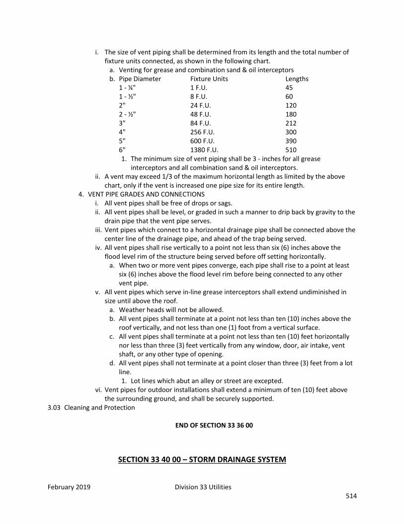
February 2019 Division 33 Utilities 514
i. The size of vent piping shall be determined from its length and the total number of fixture units connected, as shown in the following chart.
a. Venting for grease and combination sand & oil interceptors b. Pipe Diameter Fixture Units Lengths
1 - ¼" 1 F.U. 45 1 - ½" 8 F.U. 60 2" 24 F.U. 120 2 - ½" 48 F.U. 180 3" 84 F.U. 212 4" 256 F.U. 300 5" 600 F.U. 390 6" 1380 F.U. 510 1. The minimum size of vent piping shall be 3 - inches for all grease
interceptors and all combination sand & oil interceptors. ii. A vent may exceed 1/3 of the maximum horizontal length as limited by the above
chart, only if the vent is increased one pipe size for its entire length. 4. VENT PIPE GRADES AND CONNECTIONS
i. All vent pipes shall be free of drops or sags. ii. All vent pipes shall be level, or graded in such a manner to drip back by gravity to the
drain pipe that the vent pipe serves. iii. Vent pipes which connect to a horizontal drainage pipe shall be connected above the
center line of the drainage pipe, and ahead of the trap being served. iv. All vent pipes shall rise vertically to a point not less than six (6) inches above the
flood level rim of the structure being served before off setting horizontally. a. When two or more vent pipes converge, each pipe shall rise to a point at least
six (6) inches above the flood level rim before being connected to any other vent pipe.
v. All vent pipes which serve in-line grease interceptors shall extend undiminished in size until above the roof.
a. Weather heads will not be allowed. b. All vent pipes shall terminate at a point not less than ten (10) inches above the
roof vertically, and not less than one (1) foot from a vertical surface. c. All vent pipes shall terminate at a point not less than ten (10) feet horizontally
nor less than three (3) feet vertically from any window, door, air intake, vent shaft, or any other type of opening.
d. All vent pipes shall not terminate at a point closer than three (3) feet from a lot line. 1. Lot lines which abut an alley or street are excepted.
vi. Vent pipes for outdoor installations shall extend a minimum of ten (10) feet above the surrounding ground, and shall be securely supported.
3.03 Cleaning and Protection
END OF SECTION 33 36 00
SECTION 33 40 00 – STORM DRAINAGE SYSTEM

February 2019 Division 33 Utilities 515
Part 1: General 1.01 Summary
A. This section covers the installation and testing of storm drainage systems including the furnishing and installation of manhole and inlet materials, and other appurtenances
1.02 Related Sections 1.03 Definitions 1.04 Submittals Required 1.05 Quality Assurance
A. Lay pipe and set manhole inverts true to line and grade shown on Drawings. Under no circumstances shall pipe be laid which results in a level invert, reverse sloping invert, or a grade flatter than will accommodate design flows.
1.06 Scheduling 1.07 Delivery, Storage, and Handling 1.08 Regulatory Requirements
A. Use effective measures to prevent foreign material from entering the pipe. B. Do not place debris, tools, clothing, or other materials in the pipe. C. Close the open end of any pipe with a plug, or cap, to prevent the entry of foreign material or
water into the pipe. D. Use effective measures to prevent the uplift or floating of the line prior to completion of the
backfilling operation. Part 2: Products 2.01 Manufacturers 2.02 Products
A. PIPE MATERIALS 1. Type.
i. Corrugated metal pipe may only be used as culvert pipe and not as part of the storm drainage system.
ii. Minimum size will be 15-inch diameter. 2. Flared end sections shall be premanufactured flared end sections and shall meet the
minimum material specification applying to the pipe. B. MANHOLE MATERIALS
1. Same as sewer manholes except only one preformed plastic gasket is required per joint. Cast word "Storm" in the cover.
C. CONCRETE 1. Class A concrete, reference Colorado Department of Transportation, Division of Highways,
State of Colorado "Standard Specifications for Road and Bridge Construction" section 601. Sections 100 through 109 and measurement and payment provisions shall not apply.
D. INLETS 1. All inlets shall conform to the Colorado Department of Transportation, Division of
Highways, M Standards. "Standard Specifications for Road and Bridge Construction" sections 100 through 109 and measurement and payment provisions shall not apply.
2. Street inlet grates shall be of a design that is safe for bicycles. E. PIPE BEDDING
1. All pipe, regardless of type or diameter, shall be installed on sufficient bedding material so as to provide a minimum of three (3) inches separation between the subsoil and the pipe bell, after consolidation. In addition, all bedding and backfill material shall be free of frozen material, organic material, and debris.
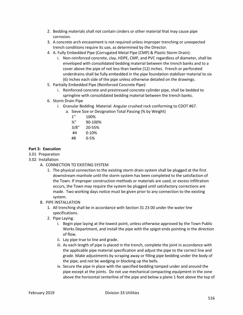
February 2019 Division 33 Utilities 516
2. Bedding materials shall not contain cinders or other material that may cause pipe corrosion.
3. A concrete arch encasement is not required unless improper trenching or unexpected trench conditions require its use, as determined by the Director.
4. A. Fully Embedded Pipe (Corrugated Metal Pipe (CMP) & Plastic Storm Drain): i. Non-reinforced concrete, clay, HDPE, CMP, and PVC regardless of diameter, shall be
enveloped with consolidated bedding material between the trench banks and to a cover above the pipe of not less than twelve (12) inches. French or perforated underdrains shall be fully embedded in the pipe foundation stabilizer material to six (6) inches each side of the pipe unless otherwise detailed on the drawings.
5. Partially Embedded Pipe (Reinforced Concrete Pipe): i. Reinforced concrete and prestressed concrete cylinder pipe, shall be bedded to
springline with consolidated bedding material between the trench banks. 6. Storm Drain Pipe
i. Granular Bedding Material: Angular crushed rock conforming to CDOT #67. a. Sieve Size or Designation Total Passing (% by Weight)
1’’ 100% ¾” 90-100% 3/8” 20-55% #4 0-10% #8 0-5%
Part 3: Execution 3.01 Preparation 3.02 Installation
A. CONNECTION TO EXISTING SYSTEM 1. The physical connection to the existing storm drain system shall be plugged at the first
downstream manhole until the storm system has been completed to the satisfaction of the Town. If improper construction methods or materials are used, or excess infiltration occurs, the Town may require the system be plugged until satisfactory corrections are made. Two working days notice must be given prior to any connection to the existing system.
B. PIPE INSTALLATION 1. All trenching shall be in accordance with Section 31 23 00 under the water line
specifications. 2. Pipe Laying.
i. Begin pipe laying at the lowest point, unless otherwise approved by the Town Public Works Department, and install the pipe with the spigot ends pointing in the direction of flow.
ii. Lay pipe true to line and grade. iii. As each length of pipe is placed in the trench, complete the joint in accordance with
the applicable pipe material specification and adjust the pipe to the correct line and grade. Make adjustments by scraping away or filling pipe bedding under the body of the pipe, and not be wedging or blocking up the bells.
iv. Secure the pipe in place with the specified bedding tamped under and around the pipe except at the joints. Do not use mechanical compacting equipment in the zone above the horizontal centerline of the pipe and below a plane 1 foot above the top of
February 2019 Division 33 Utilities 517
the pipe. Do not walk on small diameter pipe or otherwise disturb pipe after the jointing has been completed.
v. Install tracer wire with all piping. Terminate tracer wire in an approved termination box.
C. MANHOLE CONSTRUCTION 1. Same as sewer manholes. 2. Provisions as to placement, access, and water tightness of manholes from surface drainage
is the same as for sewer manholes. Manholes do not require vacuum testing. D. STORM INLET CONSTRUCTION
1. All concrete and steel reinforcing used and all concrete work done in constructing inlets shall be in accordance with the Colorado Department of Transportation, Division of Highways, "Standard Specifications for Road and Bridge Construction" and M - Standards. Specifications sections 100 through 109 and measurement and payment provisions shall not apply.
2. All casting used shall sit flush with the surrounding concrete apron. 3. C. The bottom of all inlet structures shall be formed to drain to the outlet pipe at a
minimum slope of 1 inch per linear foot. 4. D. All inlet structures will be flushed after completion and will not be accepted if water
remains in the structure. 5. The minimum size of the outlet pipe from the inlet structure shall be 15 inches in
diameter. The outlet pipe shall be laid at a minimum slope of 1%. E. FIELD QUALITY CONTROL
1. System shall meet the requirements of the following tests. Furnish all equipment, labor and incidentals necessary and conduct tests in the presence of Town.
2. Alignment Tests: i. Lamp each section of lines between manholes to determine whether any
displacement of the pipe has occurred. ii. Repair poor alignment, displaced pipe, or other defects discovered.
3. Manholes and pipe lines shall not have any visible leaks or damp spots. 4. Compaction Testing:
i. Maximum dry densities of all soil types encountered or to be used will be determined in accordance with AASHO T-99 or T-180 Methods C-D. The percent of relative compaction required will be equal to or greater than minimum values as hereinafter shown for the various classes of soil and type of compactions.
a. AASHO T-99 AASHO T-180 Soil Classification Minimum Relative Minimum Relative (AASHO M-145) Compaction Compaction
b. A-1 100 95 A-3 100 95 A-2-4 100 95 A-2-5 100 95 All Others 95 90 c. Compacted subgrade ready to receive subbase material shall conform to the
lines, grades and cross-section called for on the plans. Subgrade is to be established by survey.
3.03 Cleaning and Protection A. CLEANING
1. Prior to substantial completion remove all accumulated construction debris, rocks, gravel, sand, silt and other foreign material from the system. Use mechanical rodding or bucketing equipment as required. Any unsatisfactory work shall be removed and replaced in a proper manner. The invert of the storm drain and manholes shall be left smooth, clean, and free from any obstructions throughout the entire line. Manhole rings and covers must be raised to finished grade before acceptance of the storm drain.

February 2019 Division 33 Utilities 518
2. Upon final inspection if any foreign matter is present in the system, flush and clean the sections of the line as required.
3. Alignment Tests. i. Lamp each section of lines between manholes to determine whether any
displacement of the pipe has occurred. ii. Repair poor alignment, displaced pipe, or other defects discovered.
4. Manholes and pipe lines shall not have any visible leaks or damp spots. 5. Compact Testing Requirements.
END OF SECTION 33 40 00
SECTION 33 41 00 – STORM UTILITY DRAINAGE PIPING Part 1: General 1.01 Summary
A. This section covers plastic pipe to be used for the storm drainage culverts. B. Plastic storm drainage pipe may be used for culvert pipe and subdrainage pipe with the
approval of the local jurisdiction, but shall not be used for storm drainage pipe in a storm drain system.
1.02 Related Sections 1.03 Definitions 1.04 Submittals Required 1.05 Quality Assurance 1.06 Scheduling 1.07 Delivery, Storage, and Handling 1.08 Regulatory Requirements Part 2: Products 2.01 Manufacturers 2.02 Products
A. NON-PERFORATED CULVERT PIPE 1. Polyethylene corrugated pipe and fittings: ASTM F405 with ultra-violet resistant pigment
for sizes 3 inches through 6 inches. i. Pipe shall have a smooth interior.
2. Polyethylene corrugated pipe and fittings: ASTM F667 with ultra-violet resistant pigment for sizes 8 inches through 24 inches.
i. Pipe shall have a smooth interior. ii. Pipe ends shall contain a gasketed bell and spigot joining system. No split coupling
joining systems will be allowed. 3. Polyvinyl chloride ribbed pipe and fittings: ASTM F794 for sizes 4 inches through 48 inches. 4. High Density Polyethylene (HDPE) for sizes 4 inch to 60 inch.
i. Pipe shall have a smooth interior. ii. Pipe ends shall contain a gasketed bell and spigot joining system. No split coupling
joining systems will be allowed.
February 2019 Division 33 Utilities 519
B. PERFORATED CULVERT PIPE 1. Polyethylene corrugated pipe and fittings: HDPE, meeting the requirements of ASTM F405
for sizes 3 inches through 6 inches. 2. Polyethylene corrugated pipe and fittings: HDPE, meeting the requirements of ASTM F667
for sizes 8 inches through 2 inches. 3. Pipe exposed to sunlight shall be constructed with ultra-violet resistant pigment. 4. Geotextile: CDOT, Section 712.08, Class A Table 712-3.
Part 3: Execution 3.01 Preparation 3.02 Installation
A. INSPECTION 1. Examine pipe and fittings and do not use individual sections containing:
i. Cracks. ii. Dents. iii. Abrasions. iv. Other defects.
2. Mark rejected pipe, store at a designated remote spot on site, and remove from the site after completion of the project.
B. INSTALLATION 1. Cutting the pipe.
i. Cut pipe square with saw or pipe cutter designed specifically for the material. ii. Bevel the end in accordance with the manufacturer's recommendations. iii. Insert the spigot to the reference mark, according to manufacturer's
recommendations. iv. Do not disturb previously installed joints during jointing operations.
2. Pipe shall be centered horizontally in the trench. 3. Wrap the bedding material of perforated culvert pipe with geotextile fabric. 4. All piping to have tracer wire installed. Tracer wire to terminate in approved termination
box. 3.03 Cleaning and Protection
END OF SECTION 33 41 00
SECTION 33 46 13.13 – FOUNDATION DRAINAGE Part 1: General
A. Foundation drainage system work as shown on the drawings for: 1. Perimeter drainage system.
1.02 Related Sections 1.03 Definitions 1.04 Submittals Required
A. Certification 1.05 Quality Assurance 1.06 Scheduling

February 2019 Division 33 Utilities 520
1.07 Delivery, Storage, and Handling 1.08 Regulatory Requirements Part 2: Products 2.01 Manufacturers 2.02 Products
A. DRAINAGE PIPE AND ACCESSORIES: 1. Piping:
i. Furnish drainage pipe complete with bends, reducers, adapters, couplings, collars, and joint materials.
ii. Polyvinyl Chloride Pipe: ASTM D2729, perforated and plain. 2. Accessory Materials:
i. Filter Fabric: Mirafi 140N, Typar Style 3401 by DuPont, or approved equal, 4 oz. per sq. yd. polypropylene fabric.
B. SOIL MATERIALS: 1. Backfill: Soil materials as approved for fill and backfill. 2. Drainage Fill: Uniformly graded mixture of natural or crushed gravel, crushed stone, and
natural sand with 100% passing a 1.5" sieve and 0-5% passing a 0.25" sieve.
Part 3: Execution 3.01 Preparation 3.02 Installation
A. Perimeter Foundation Drainage System: 1. Grade perimeter drain trenching to permit positive drainage not less than 0.125" per ft.
B. Filtering Material: 1. Line bottom and sides of trench with filter fabric with single width, extended up sides of
trench to permit full lap when folded over top of drainage fill. 2. Place a supporting layer of drainage fill material on filter fabric over compacted subgrade
where drainage pipe is to be laid to the depth indicated or, if not indicated, to a compacted depth of not less than 4".
C. Laying Drain Pipe: 1. Lay drain pipe solidly bedded in drainage fill material. 2. Provide full bearing for each pipe section throughout its length, to true grades and
alignment, and continuous slope in the direction of flow. 3. Lay perforated pipe with perforations down and joints tightly closed in accordance with
pipe manufacturer's recommendations. 4. Provide collars and couplings as required. 5. Extend from low point of drainage system with unperforated pipe to daylight discharge or
storm sewer sump as shown on drawings. Sump, pump and cover are included in Division 26 sections.
D. Testing Drain Lines: Test or check lines before backfilling to assure free flow. Remove obstructions, replace damaged components, and retest system until satisfactory.
E. Drainage Fill: Place drainage fill over drain lines after satisfactory testing. Completely cover drain lines to a width of at least 6" on each side and 12" above top of pipe, unless more coverage is indicated on the drawings. Place fill material in layers not exceeding 3" in loose depth and compact each layer placed. 1. Fold filter fabric over top of drainage fill with full lap.
F. Fill to Grade:

February 2019 Division 33 Utilities 521
3.03 Cleaning and Protection END OF SECTION 33 46 13.13
SECTION 33 44 16 – TRENCH DRAIN SYSTEM Part 1: General 1.01 Summary
A. Modular trench drain system pre-cast from corrosion resistant polyester including interlocking modular components for on-site installation.
1.02 Related Sections 1.03 Definitions 1.04 Submittals
A. Shop Drawings B. Recommended Method of Installation
1.05 Quality Assurance A. Manufacturer/ Installer’s Experience
1. At least five (5) acceptable installations within the past five (5) years. B. Warranty
1. 2 year coverage period. 1.06 Scheduling 1.07 Delivery, Storage, and Handling 1.08 Regulatory Requirements Part 2: Products 2.01 Manufacturers
A. Manufacturer shall be ACO Polymer Products, Inc., Chardon, OH (800) 543-4764 or approved equal.
2.02 Products A. Physical and Mechanical Characteristics:
1. Overall Width 6.1 inches 2. Internal Width 4.0 inches 3. Unit Depth 7.6 inches 4. Compressive Strength of specified polymer concrete – 14,000 psi 5. Flexural strength of specified polymer concrete – 3,000 psi 6. Water absorption rate – not to exceed 0.1% by weight
B. Channel Profile: 1. Shall include positive interlocking tongue and groove connections that can be sealed to
provide watertight connections. Each pre-cast polymer concrete one meter (39.37”) unit shall be an open U-shaped channel to accept a grate 4.84” wide.
C. Grates: 1. Standard ACO Drain grates (or approved equal) and locking mechanism, galvanized steel
slotted. D. Catch Basins:
1. Shall be pre-cast polymer concrete one half meter (19.69”) in length and include a trash bucket and removable grating.
Part 3: Execution

February 2019 Division 33 Utilities 522
3.01 Preparation A. Excavate the area for channel placement wide enough and deep enough to accommodate the
channel size and a minimum of 4-inch concrete encasement. Channels require a minimum of four inches of concrete support on both sides as well as underneath the channel and top of channel must be evenly aligned to the surface of the surrounding slab.
3.02 Installation A. Install in strict accordance with manufacturer’s recommendations and contract documents. B. Channel sections are installed from the outlet ends of the system, working from the catch basins.
Insert channels from above to allow ends to interlock. Channel sections shall be placed on rebar basket, low slump concrete grout slurry, or suspended to obtain correct finished elevation. Cutting will be made, if required, by masonry or concrete saw. Temporarily place grate in channel to avoid compression during concrete placement. Protect grated and channel interior during concrete pour.
3.03 Cleaning and Protection
END OF SECTION 33 44 16
SECTION 33 71 73 – ELECTRICAL UTILITY SERVICE Part 1: General 1.01 Summary 1.02 Related Sections 1.03 Definitions 1.04 Submittals 1.05 Quality Assurance 1.06 Scheduling 1.07 Delivery, Storage, and Handling 1.08 Regulatory Requirements Part 2: Products 2.01 Manufacturers 2.02 Products
A. Main Distribution Switchboard/Panelboards: Copper or tin-plated aluminum bus bars. Prefer Square D or Siemans/ITE or approved equal by the City of Fort Collins Electrical Department.
B. Safety Switches: Heavy-duty type fusible or nonfusible, NEMA rating for environment installed. Prefer Square D or approved equal.
C. Transformers shall be high efficiency type. (PowerSmith to be approved) Sound levels shall not exceed level listed by ANSI-C89. Transformers to be mounted with additional isolation pads and electrical connections made with flexible conduit.
D. Electrical services to include 25% spare capacity for future. E. Provide 25% spare capacity and space in all branch circuit panels. F. Provide 3 spare fuses for each size installed. Provide appropriate size spare fuse cabinet to store
spare fuses. G. Label all spare conduits on each end as to where it originates and terminates
February 2019 Division 33 Utilities 523
Part 3: Execution 3.01 Preparation 3.02 Installation
A. Install ¾” conduit from electric meter(s) to main com/data room. B. Install ¾” conduit from gas meter(s) to main com/data room. C. Install ¾” conduit from water meter(s) to main com/data room.
3.03 Cleaning and Protection
END OF SECTION 33 71 73 SEE SEPARATE AMENDMENTS FOR THE FOLLOWING:
A. STORMWATER MANAGEMENT B. QUALITY ASSURANCE / QUALITY CONTROL C. BLDG. ENVELOPE AIR BARRIER DWG. D. THERMAL BRIDGING E. PARAPET DETAIL F. DUST CONTROL DOCUMENT
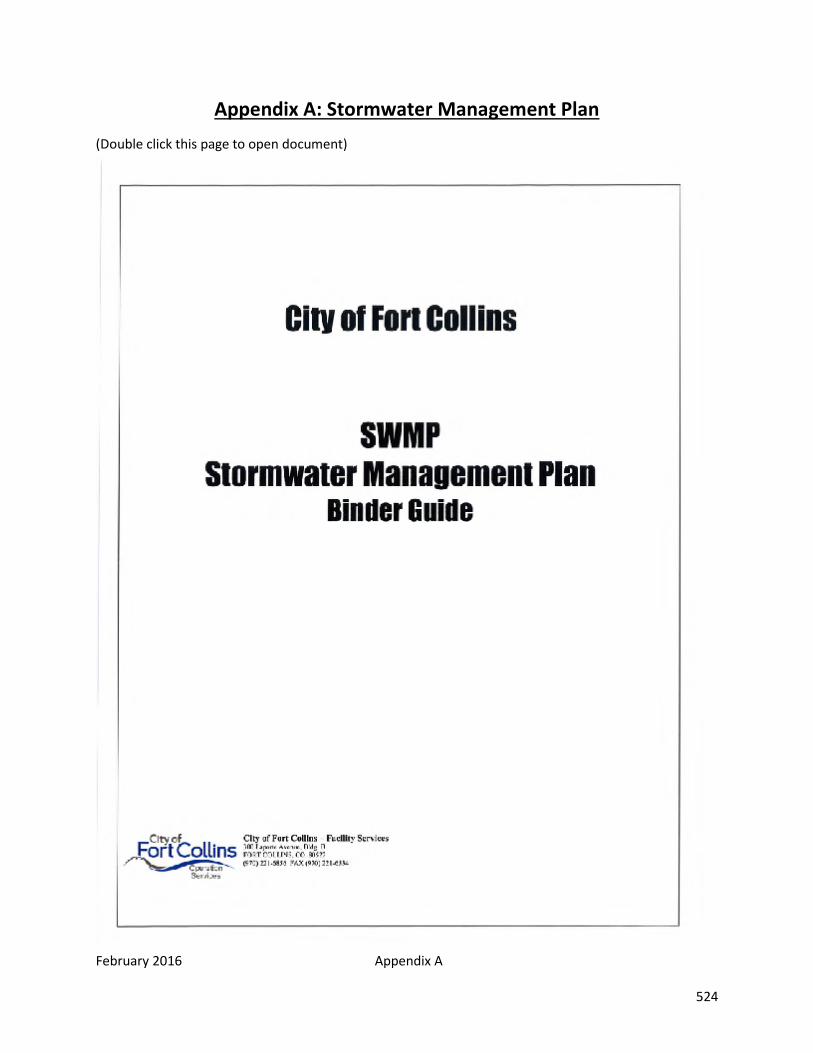
February 2016 Appendix A 524
Appendix A: Stormwater Management Plan (Double click this page to open document)

February 2016 Appendix B 525
Appendix B: Quality Assurance / Quality Control Plan (Double click this page to open document)
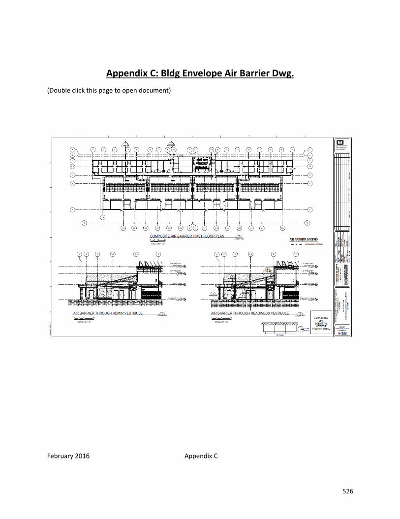
February 2016 Appendix C 526
Appendix C: Bldg Envelope Air Barrier Dwg. (Double click this page to open document)
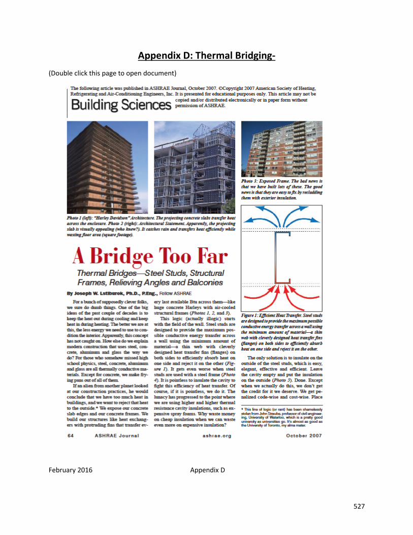
February 2016 Appendix D 527
Appendix D: Thermal Bridging- (Double click this page to open document)

February 2016 Appendix E 528
Appendix E: PARAPET DETAIL (Double click this page to open document)

February 2016 Appendix F 529
Appendix F: Dust Control Document (Double click this page to open document)
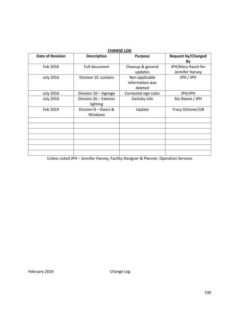
February 2019 Change Log 530
CHANGE LOG Date of Revision Description Purpose Request by/Changed
By Feb 2016 Full document Cleanup & general
updates JPH/Mary Rasch for
Jennifer Harvey July 2016 Division 10 -Lockers Non applicable
information was deleted
JPH / JPH
July 2016 Division 10 – Signage Corrected sign color JPH/JPH July 2016 Division 26 – Exterior
lighting Darksky info Stu Reeve / JPH
Feb 2019 Division 8 – Doors & Windows
Update Tracy Ochsner/JJB
Unless noted JPH – Jennifer Harvey, Facility Designer & Planner, Operation Services