Embed Size (px)
Citation preview
Design and Construction of
Highway Pavement Joint Systems
Dowel and Tie Bar
Design Considerations
Part 1
Mark B. Snyder, Ph.D., P.E.
Engineering Consultant to the
American Concrete Pavement Association

INTRODUCTION: THE NEED FOR
MECHANICAL LOAD TRANSFER

Load Transfer
Ability of a slab to share load with neighboring slabs through shear mechanism(s)
Factors affecting load transfer:Load transfer mechanisms:
Dowels/Tie Bars
Aggregate Interlock
Keyways
Edge supportWidened lanes, tied concrete shoulders or curb and gutter
Decrease edge & corner stresses & deflections
Foundation shear (stiffness)

WheelLoad
0% Load Transfer
Direction of Traffic
Approach Slab Leave Slab
100% Load Transfer
Approach Slab
WheelLoad Direction of Traffic
Leave Slab
Deflection Load Transfer
UnloadedLT (%) =
LoadedX 100

Concrete Pavement Deflections
12 ft Lanes
Outside Pavement Edge
Longitudinal Centerline
(acts as tied PCC Shoulder)
Undoweled Transverse Joint Doweled Transverse Joint
2 Di
3 Di5 Di
3 Di
Di Di
Effects of Joint Load Transfer on
Pavement Behavior

LTE is a measure of system behavior, not dowel
equivalence.
LTE is worthless without overall deflection
reference
Example #1: dUL = 0.025mm, dL = 0.05mm, LTE =
50% … but is this bad?
Example #2: dUL = 4mm, dL = 5mm, LTE = 80% …
but is this good?
LTE as a measure of equivalence?

Joint Load Transfer ConsiderationsLTE vs. Relative Deflection
Source: Shiraz Tayabji, Fugro Consultants, Inc.

ACI 360 definition: “… a joint’s ability to limit
differential deflection of adjacent slab panel edges
when a service load crosses the joint … (t)he
smaller the measured differential deflection
number the better the joint stability.”
Joint Stability

ACI 360.R-10):
< 0.010 in. (0.25 mm) (small, hard-wheeled lift truck traffic)
< 0.020 in. (0.51 mm) (larger, cushioned rubber wheels)
What is appropriate for road pavements?
Should the criterion vary with functional applications (e.g., streets vs highways)?
Should the criterion vary with foundation design and environmental conditions (e.g., stabilized vs unbound base, and wet vs dry climate)?
Joint Stability

Transverse Joint Load Transfer Systems
➢Originally: aggregate interlock
➢1920s – present: mainly round
steel dowels
▪Some trials of different shapes and
materials
▪Pre-positioned using baskets
▪Automatically placed using DBIs

Aggregate Interlock
Shear between aggregate particlesbelow the initial saw cut
May be acceptable for:• Few heavy loads• Hard, abrasion-resistant
coarse aggregate• Joint movement <0.03”

Q: How Long Have Dowels Been In Use?
A: 100 Years! (Almost As Long as PCCP)
1865 – First concrete pavement in the world built in
Inverness, Scotland
1893 – First concrete pavement built in the U.S.
(Court Street, Bellefontaine, OH)
1917-1918 – First use of dowel bars in concrete
pavement transverse joints in the U.S.

A Brief History of U.S. Dowel Design
First U.S. use of dowels in PCCP: 1917-1918 Newport News, VA Army
Camps
Two ¾-in dowels across each 10-ft lane joint
Rapid (but non-uniform) adoption through ‘20s and ‘30s
1926 practices: two ½-in x 4 ft, four 5/8-in x 4 ft, eight ¾-in x 2 ft
By 1930s, half of all states required dowels!
Numerous studies in ‘20s, ’30s, ‘40s and ‘50s (Westergaard, Bradbury,
Teller and Sutherland, Teller and Cashell, and others) led to 1956 ACI
recommendations that became de facto standards into the ‘90s:
Diameter – D/8, 12-in spacing
Embedment to achieve max LT: 8*dia for 3/4-in or less, 6*dia for larger
dowels. 18-in length chosen to account for joint/dowel placement variability.
Recent practices:Trend toward increased diameter, some shorter lengths

Current Dowel Bars (Typical)
Typical length = 18 in
Typical diameter
Roads: 1.0 - 1.5 in
Airports: 1.5 - 2.0
Epoxy or other coating
typically used in harsh
climates for corrosion
protection

Illustrates recent trend toward larger dowels to
reduce bearing stresses and minimize joint faulting and deflections.
SHA Practices for dowel diameter by
pavement thickness
Slab Thickness (in) 6.0 6.5 7.0 7.5 8.0 8.5 9.0 9.5 10.0 10.5 11.0 11.5 12.0 12.5
California 1.250 1.250 1.250 1.250 1.250 1.500 1.500 1.500 1.500 1.500 1.500 1.500 1.500 1.500
Iowa 0.750 0.750 0.750 0.750 1.250 1.250 1.250 1.250 1.500 1.500 1.500 1.500 1.500 1.500
Ill inois 1.000 1.000 1.250 1.250 1.500 1.500 1.500 1.500 1.500 1.500 1.500 1.500 1.500 1.500
Indiana 1.000 1.000 1.000 1.000 1.000 1.000 1.250 1.250 1.250 1.250 1.250 1.250 1.250 1.500
Michigan 1.000 1.000 1.000 1.000 1.250 1.250 1.250 1.250 1.250 1.250 1.250 1.500 1.500 1.500
Minnesota 1.000 1.000 1.250 1.250 1.250 1.250 1.250 1.250 1.250 1.500 1.500 1.500 1.500 1.500
Missouri N/A N/A 1.250 1.250 1.250 1.250 1.250 1.250 1.250 1.500 1.500 1.500 1.500 1.500
North Dakota 1.250 1.250 1.250 1.250 1.250 1.250 1.250 1.250 1.250 1.500 1.500 1.500 1.500 1.500
Ohio 1.000 1.000 1.000 1.000 1.000 1.250 1.250 1.250 1.250 1.500 1.500 1.500 1.500 1.500
Texas N/A N/A N/A N/A 1.000 1.125 1.250 1.375 1.500
Wisconsin N/A N/A 1.000 1.000 1.250 1.250 1.250 1.250 1.500 1.500 1.500 1.500 1.500 1.500

Dowels:
Critical Structural Components of JCP
Provide Load Transfer
Reduce slab stresses
Reduce slab deflections, potential for erosion of support
Restraint of Curl/Warp Deformation
Influence Dowel-Concrete Bearing Stress
Need to last for expected pavement service life
(corrosion resistance, other durability)
20 – 35 years for conventional pavement and repairs
40 - 100 years for long-life pavements

Dowel Diameter/Cross-Section (including plate dowels)Dowel Bar LengthDowel Alignment Requirements
Vertical TranslationLongitudinal Translation
Dowel Spacing and Number of DowelsCorrosion Protection
Epoxy CoatingsAlternate Dowel Materials and Coatings
Stainless SteelMicrocomposite SteelZinc Alloy-Sleeved SteelFRP/GFRPFRP/GFRP over Steel
Dowel Bar Lubrication/Bond-breaker MaterialsUse of Expansion Caps/Joint Forming Materials
Dowel Load Transfer System
Design Considerations

CONSIDERATION OF DOWEL SHEAR,
BENDING AND BEARING STRESSES

LT achieved through both shear and moment transfer,
but moment contribution is small (esp. for joint widths of
¼” or less).
Shear capacity of dowel is not critical, but…
Shear capacity of concrete (cover)?
Bearing stress at joint/crack face?
Maximum load transferred varies with slab thickness,
foundation support, dowel layout, load placement, etc.
Bearing stresses can be critical to performance!
Dowel LT Design Considerations

Not a standard, not tied to pavement
thickness
A part of concrete pavement system design
Impacts faulting, IRI and other performance
measures through resulting bearing stress,
differential deflection, deflection energy, etc.
Dowel Diameter

Estimating Critical Dowel Load
l = (ECh3/12k(1 – μ2))0.25
Typical critical dowel load < 3000 lbs


Timoshenko & Lessel’s
Wire Deflection Equation
x)]-x(M-xP[IE2
e=y oCrit
s
2
x-
sincoscos
y = Deflection in steel = Relative stiffness of steel-concrete systemx = Distance from face of concreteMo = Bend. moment at face of concrete (Mo= -Pt z/2)z = Crack widthPCrit = Load transferred by critical wire

σb = Ky0 = KPt(2 + βz)/4β3EdId
β = (Kd/4EdId)0.25
Id = = πd4/64 for round dowels
Friberg’s Dowel-Concrete Bearing Stress

ACI 325 (1956)
fb = f’c(4 – d)/3where:
fb = allowable bearing stress, psi
f’c = PCC 28-day compressive strength, psi
d = dowel diameter, inches
Provided factor of safety of 2.5 to 3.2 against bearing stress-related cracking
Withdrawn from ACI 325 in 1960s, no replacement guidance provided
Still commonly cited today …


Impact of Dowel Diameter on Joint Faulting
0
0.05
0.1
0.15
0.2
0.25
0.3
0.35
0 50 100 150 200 250 300 350
Age, months
Fau
ltin
g f
or
10 i
nch
sla
b, in
s
1" dia dowel
1.25" PCC
1.375" PCC
1.5" dia dowel
Example for 10-in slab with specific traffic and climate … not a design chart!

COPES Model: Bearing Stress vs Joint Faulting

Not a standard, not tied to pavement
thickness
A part of concrete pavement system design
Impacts faulting, IRI and other performance
measures through resulting bearing stress,
differential deflection, deflection energy, etc.
Manufacturers of all products should produce
standard diameters (to facilitate use of
standard basket sizes)
Recommendations: Dowel Diameter

DOWEL DESIGN:
DIMENSIONS, PLACEMENT AND MATERIALS

Standard typically 18 in (since 1950s)Based on embedment requirements to match behavior of Timoshenko 1925 analysis (semi-infinite embedded bar)A few states successfully use shorter dowels (e.g., 14 inches in MN)Shorter embedment lengths are supported by research dating to 1950sShorter lengths may be feasible for retrofit dowels and full-depth repairs where dowel position is well-controlled
Dowel Length

Teller and Cashell, 1959
Khazanovich et al, 2009

For round, metallic dowels, provide a
minimum of 4 inches of embedment on each
side of joint
Select dowel length to include embedment
requirements and tolerances for placement
and joint sawing variability
Shorter dowels are possible for retrofit and full-
depth repairs where dowel placement and joint
location are known more precisely
Recommendations: Dowel Length


Typically required to be
placed at mid-depth
Maximize concrete cover
(top and bottom)
Dowel load and moment do
not change significantly
with vertical placement –
reduced cover is feasible, if
necessary
Dowel Vertical Position in Slab

Odden et al, 2004
Khazanovich et al, 2009

In-range or upsize placements within 1 inch of mid-
depth
Downsize use placements within 2 inches of mid-
depth (closer to bottom than top)
Vertical translation tolerances supported by testing
and experience
Recommendations:
Dowel Vertical Location in Baskets
Dowel Bar Diameter, in 0.75 1.0 1.25 1.5 1.75 2.0
Height to Dowel Center, in 2.5 3.0 4.0 5.0 6.0 6.0
Intended Slab Thickness, in 5 – 6 6 – 8 8 – 10 >10 >12 >12
Distance Between Dowel Center and Slab Mid-Depth, in
0 – 0.5 0 - 1 0 - 1 0 - ? 0 - ? 0 - ?

“OPTIMIZATION” OF DOWEL LOCATION

Trend toward reducing standard dowel installations from 12 dowels per 12-ft lane to 11
Increase distance from lane edge to outside dowels to reduce incidence of paver-induced misalignment
Concentrated dowels in wheel pathsCommon in dowel bar retrofit applications
Some trends for new construction
Evaluate bearing stresses
for alternate spacings using
DowelCAD software
“Optimized” Dowel Spacing

du
Traffic

Illinois Tollway
Rural Minnesota State Highway


Reduce bearing stress while holding cross-
sectional area constant (or reducing it)
Examples:
Elliptical Dowels
Plate Dowels
Hollow Dowels (MnDOT)
“Optimized” Dowel Designs


Restraint of Movements in Area Pavements

Isolated Circle
Restraint of Odd-shaped Panels and Roundabouts

Various Plate Dowel Assemblies
Source: ACI 360 R-10

Plate Dowel Geometriesfor Contraction Joints
Sawcut at boundary of installation tolerance
Center
line
Tolerance
line
Formed void space on vertical sides of plate
Tolerance
line


Plate Dowels at MnROAD:
Preliminary Test Results
>2.5 million ESALs to date
Performance Summary
Joint performance is good
Joint deflection less than round dowels
Consolidation is good
LTE in acceptable range
Less cracking
3/8” x 12” PD3 basket assembly
Core sample showing
consolidation above and
below plate

Plate dowels for slip-formed or‘new-to-existing’ joints

Epoxy-grouted CoVex™ Plates
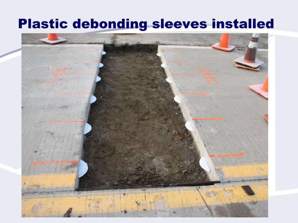
Plastic debonding sleeves installed

Source: The Fort Miller Company, Inc.

• Light weight
• 6’ x 6’ weighs 2 T
• Vertically removable & replaceable
• Warped as required to fit any surface
• Standard warps are in stock
• Removable and reusable
Super-Paver – A Re-usable Urban
Pavement (RUP) System
(Designed specifically for utility-intensive urban highways
and intersections)
The Fort Miller Co., Inc.
Source: The Fort Miller Company, Inc.

Slab Removal & Replacement
The Fort Miller Co., Inc.
Source: The Fort Miller Company, Inc.

Source: The Fort Miller Company, Inc.

PREVENTION OF
CORROSION-RELATED PROBLEMS

The Corrosion Problem
Corrosion - the destruction or deterioration
of a metal or alloy substrate by direct
chemical or electrochemical attack.
Corrosion of reinforcing steel and dowels in
bridges and pavements causes cracking
and spalling.
Corrosion costs an estimated $276B per
year in the U.S. alone!
Corroded dowels obtained from in-service JCP.

Effects of Corrosion on JCP
Dowels
Loss of Cross-Section at Joint
Poor Load Transfer
Reduced Curl-Warp Restraint
Joint Lockup (Corrosion Products)
Spalling
Crack Deterioration
Premature Failure

Dowel Corrosion Solutions:
Barrier Techniques
Form Oil, Grease, Paint,
Epoxy, Plastic
Coating breach
corrosion failure
Stainless Steel Cladding
and Sleeves
Relatively expensive
Corrosion at coating
breaches (including ends),
accelerated due to
galvanic reaction.

Dowel Corrosion Solutions:
Corrosion-Resistant/Noncorroding Materials
Stainless Steel (Solid, Tubes)
Expensive (solid bars and, to a
less extent, grout-filled tubes)
Deformation and slab cracking
concerns (hollow tubes only)
“Microcomposite” Steel
Sufficient corrosion
resistance?
GFRP Products
Not yet widely adopted
Concerns over behavior,
durability

Dowel Corrosion Solutions:
Barrier/Cathodic Protection
Galvanic (Sacrificial)
Inexpensive and self-
regulating
Appears well-suited for
pavement dowel
applications (zinc cladding
or sleeve)

Epoxy Coatings
Most common approach to
corrosion prevention since
1970s
Long-term performance has
varied with environment,
coating properties, construction
practice and other factors
Sometimes unreliable for long
performance periods.
Photo credit: Tom Burnham, MnDOT
Photo credit: Washington State DOT

Typical product: AASHTO M254/ASTM
775 (green, “flexible”)
ASTM 934 (purple/grey, “nonflexible”)
has been suggested
Perception of improved abrasion
resistance (but green meets same spec
requirement)
Mancio et al. (2008) found no difference
in corrosion protection
What is needed:
Durability, resistance to damage in
transport, handling, service
Standardized coating thickness
Dowel Epoxy Coatings

Epoxy Coatings for Dowels:
Better Stuff is Available!
Simplex Supply Armour Coat – 2-layer fusion-bonded system

Remains least expensive, potentially effective option
Only effective if durable and applied with sufficient
and uniform thicknessConsider use of improved epoxy materials
10-mil nominal minimum thickness meets or exceeds
requirements of all surveyed statesWould allow individual measures as thin as 8 mils if
average exceeds 10 mils
Probably not necessary to specify upper limitSelf-limiting due to manufacturer costs
Potential downside is negligible for dowels
Recommendations: Epoxy Coating

Many materials are suitable
Selection should consider environmental conditions,
design requirements (performance life), cost
considerations
Structural, behavioral considerations favor continued use of
metallic products
no design adjustments needed (dowel diameter, spacing)
For LLCP, stainless steel (316L) and zinc-sleeved products
offer the best combination of predictable structural
behavior and corrosion resistance
Microcomposite steel is less corrosion-resistant; epoxy
coating may be appropriate for long-life applications
What about FRP dowels (E of FRP is 20% of steel E)?
Dowel Bar Materials

Modifying FRP Dowel LT System
Design for Structural Equivalence with
Metallic Dowels
Dowel Type Diameter
(in) Dowel Modulus, E
(psi) Applied Shear Force
(lbs)
Dowel Deflection
at Joint Face (in)
Bearing Stress (psi)
Metallic 1.50 29,000,000 1940 (12-in spacing) 0.0009 1405
Sch 40 Pipe 1.66 29,000,000 1940 (12-in spacing) 0.0009 1421
FRP 1.50 5,600,000 1940 (12-in spacing) 0.0015 2185
FRP 1.93 5,600,000 1940 (12-in spacing) 0.0009 1393
FRP 1.50 5,600,000 1293 (8-in spacing) 0.0010 1456

Davis and Porter (1998)
Similar joint LTE for 44-mm FRP @ 8 in and 1.5-in steel @ 12 in
Melham (1999)
1.5-in FRP performed comparably to 1.0-in steel
FHWA TE-30 (IL, WI, IA, etc.)
IL (Gawedzinski, 2004): FRP LTE lower and more variable
IA (Cable and Porter, 2003): FRP dowel max spacing 8-in; horizontal delamination observed in core.
WI (Crovetti, 1999): Significantly reduced LTE for FRP dowels, but no performance differences in short term
Larson and Smith (2005): “… low LTEs of FRP dowels in less than 5 years is a serious concern.”
Odden et al., Popehn et al., 2003 (U-Mn)
Many studies of FRP dowels …

Guide and Tech Brief
Now Available!
National Concrete Pavement
Technology Centerat
Iowa State University

Summarizes factors and design theories that should be considered in dowel load transfer system designIncludes practical considerations and results of NCC surveys and discussions concerning dowel basket design and fabricationDiscusses alternate dowel materialsPresents recommendations for widespread adoption (i.e., standardization)
Basket wire sizesBasket height as function of dowel diameterDoes NOT recommend dowel diameter for various pavement thicknessesDowel length and spacing
Appendices with additional support documentation
NCC/CP Tech Brief

DESIGN AND EVALUATION OF
TIE BAR SYSTEMS

JRCP Reinforcement Design:
“Subgrade Drag Theory”
As(min) = T/fs
As(min) = Minimum area of steel required (per foot width of pavement) to hold
cracks tight
fs = Allowable working stress = 0.75(yield stress of steel)
T = Max. Tensile Force developed in steel (per foot width)
= L/2*(unit width)*hc*gc*F
L = Distance between working jts or pavement edges, ft
hc = Slab thickness, ft
gc = Unit weight of concrete, pcf (140-150 pcf)
F = friction coefficient between slab and underlying layer (see 1993 AASHTO
p II-28)

‘93 AASHTO Design Nomographs

ACPA M-E Tie Bar
Designer App

Source: The Fort Miller Co., Inc.

Source: The Fort Miller Co., Inc.
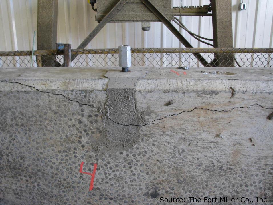
Source: The Fort Miller Co., Inc.

6-inch headed ties:Average pullout = 22.2 kips (range = 18.16 – 25.32)
Keyed average: 22.71 kips
No-key average: 21.41 kips
7-inch headed ties:Average pullout = 25.9 kips (range = 24.02 – 27.26)
Keyed average: 25.75 kips
No-key average: 26.13 kips
TxDOT Std 361.3 requires 0.75*yield strength (19.9 kips for #6 bars, Grade 60 steel) for repair work
Test Results
But what do we really need???Source: The Fort Miller Co., Inc.

Typically required to be
placed at mid-depth in U.S.
Maximize concrete cover
(top and bottom)
Germany places tie bars
2/3 from top
Dowel load and moment do
not change significantly
with vertical placement
Dowel/Tie Bar Vertical Position in Slab

Beware of Dowel-Tie Interference!!
Hold tie bars at least
15” from transverse
joints (many states
use 30” …)