Embed Size (px)
Citation preview
Design and Construction of
Highway Pavement Joint Systems
Dowel and Tie Bar
Design Considerations
Part 2
Mark B. Snyder, Ph.D., P.E.
Engineering Consultant to the
American Concrete Pavement Association
Dowel Alignment and
Location Requirements
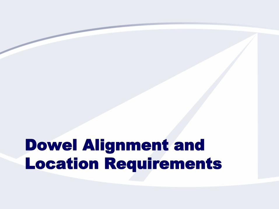
The Goal
Dowels that are:
Aligned such that they
impose no intolerable
restraint on joint
opening/closing
Located such that they provide adequate long-term
load transfer
Are not so close to the surface or subbase as to cause
shear failures
Have the required embedment depth
Are not too far from (or close to) each other or the
pavement edge
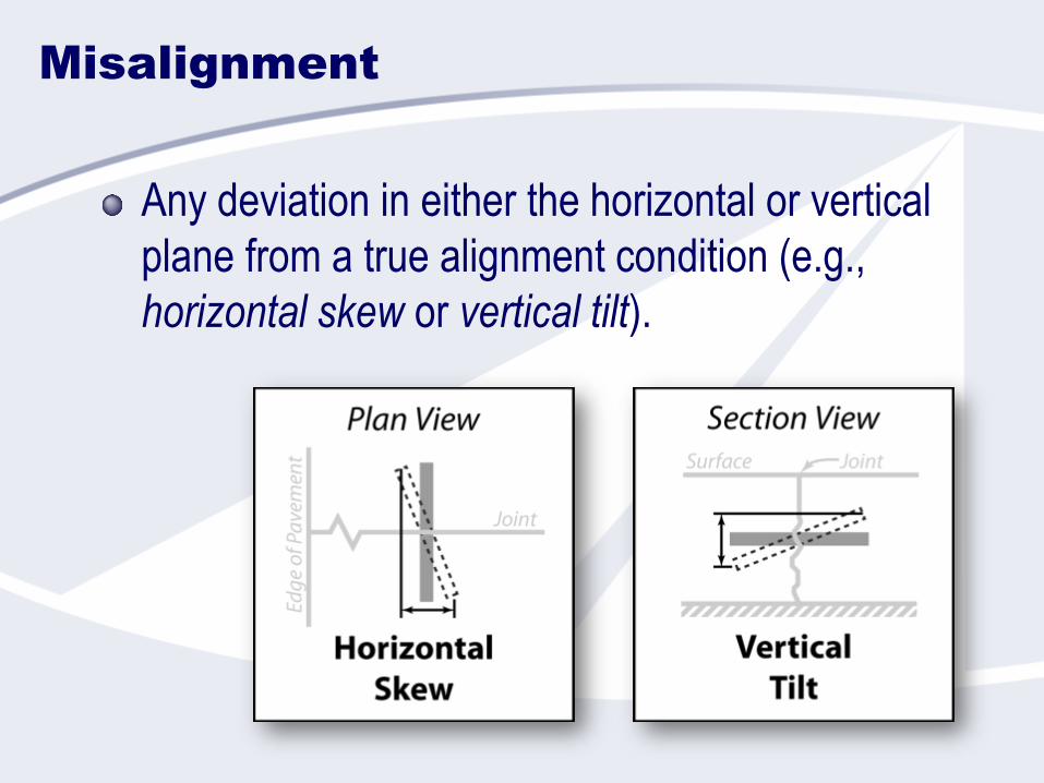
Misalignment
Any deviation in either the horizontal or vertical
plane from a true alignment condition (e.g.,
horizontal skew or vertical tilt).
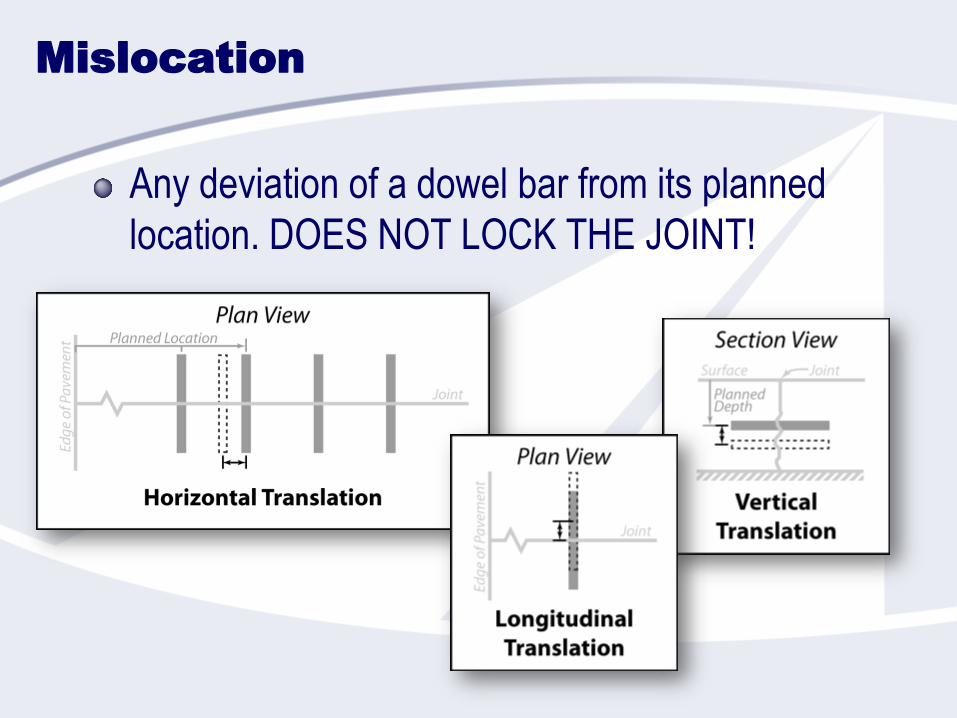
Mislocation
Any deviation of a dowel bar from its planned
location. DOES NOT LOCK THE JOINT!
Sources of Misalignment
and Mislocation
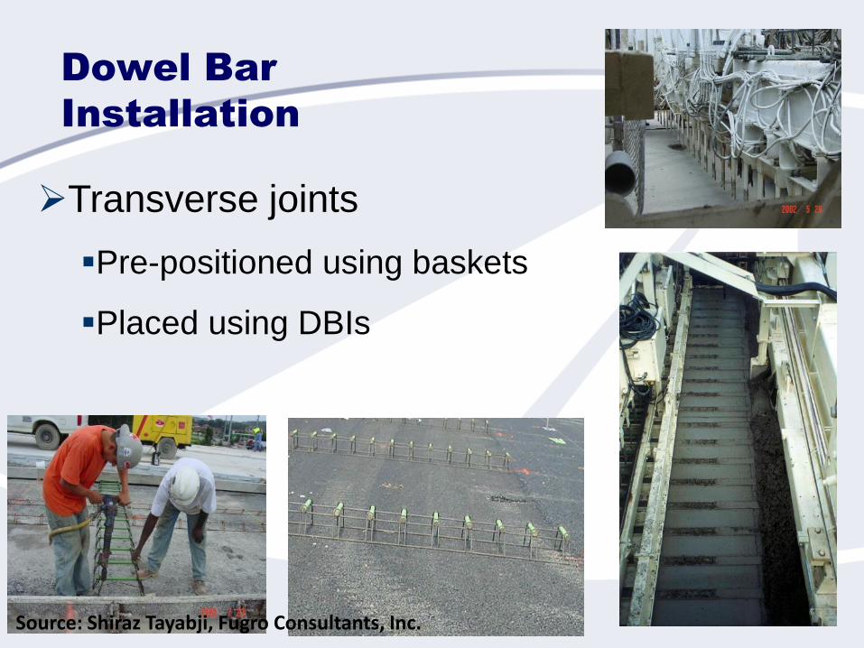
Dowel Bar
Installation
➢Transverse joints
▪Pre-positioned using baskets
▪Placed using DBIs
Source: Shiraz Tayabji, Fugro Consultants, Inc.
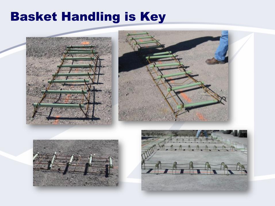
Basket Handling is Key
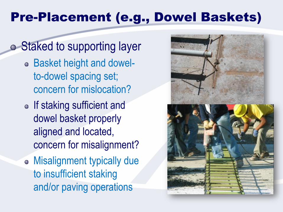
Pre-Placement (e.g., Dowel Baskets)
Staked to supporting layer
Basket height and dowel-
to-dowel spacing set;
concern for mislocation?
If staking sufficient and
dowel basket properly
aligned and located,
concern for misalignment?
Misalignment typically due
to insufficient staking
and/or paving operations
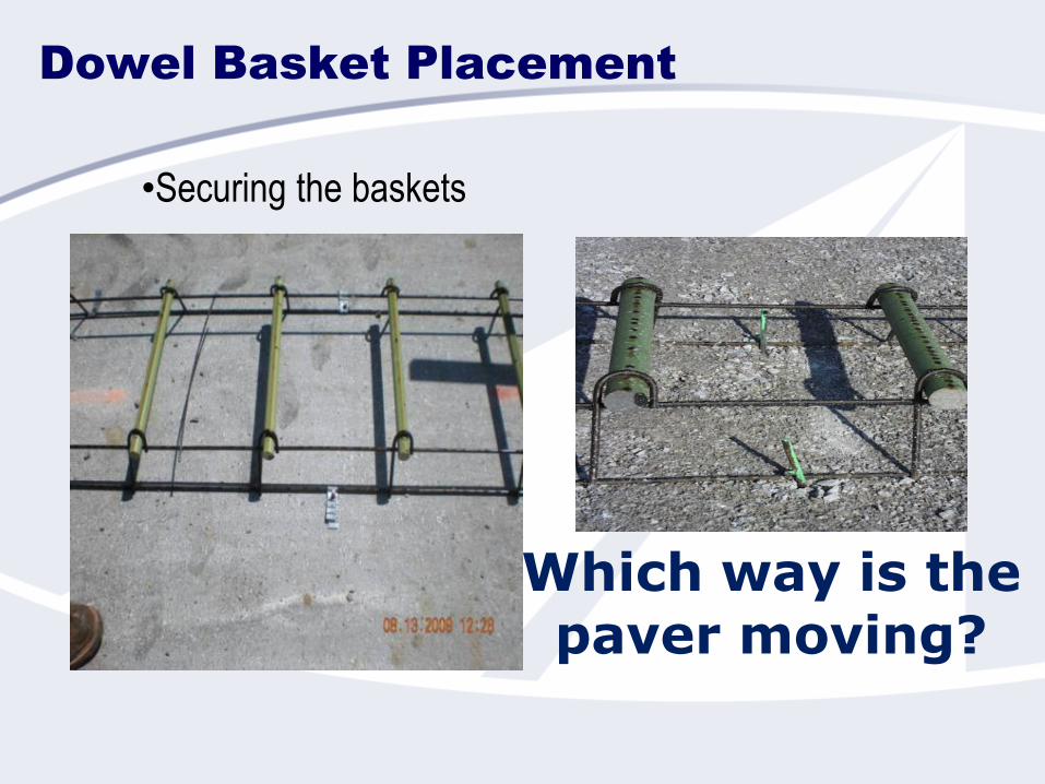
Dowel Basket Placement
Which way is the paver moving?
•Securing the baskets
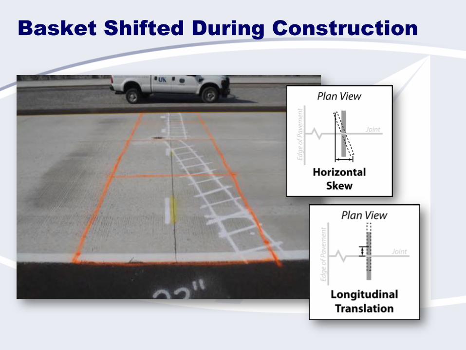
Basket Shifted During Construction
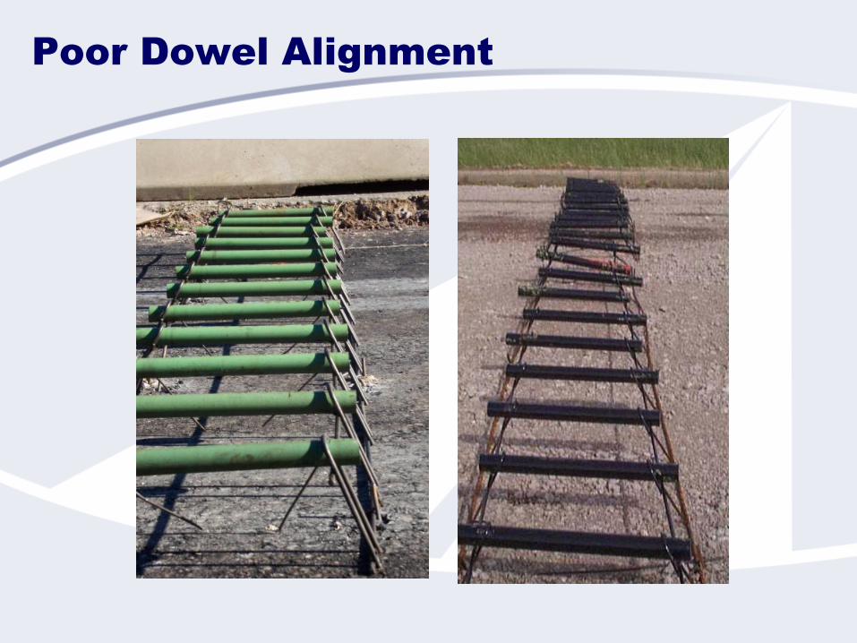
Poor Dowel Alignment
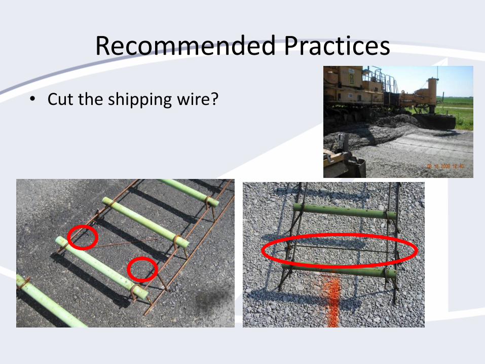
Recommended Practices
• Cut the shipping wire?
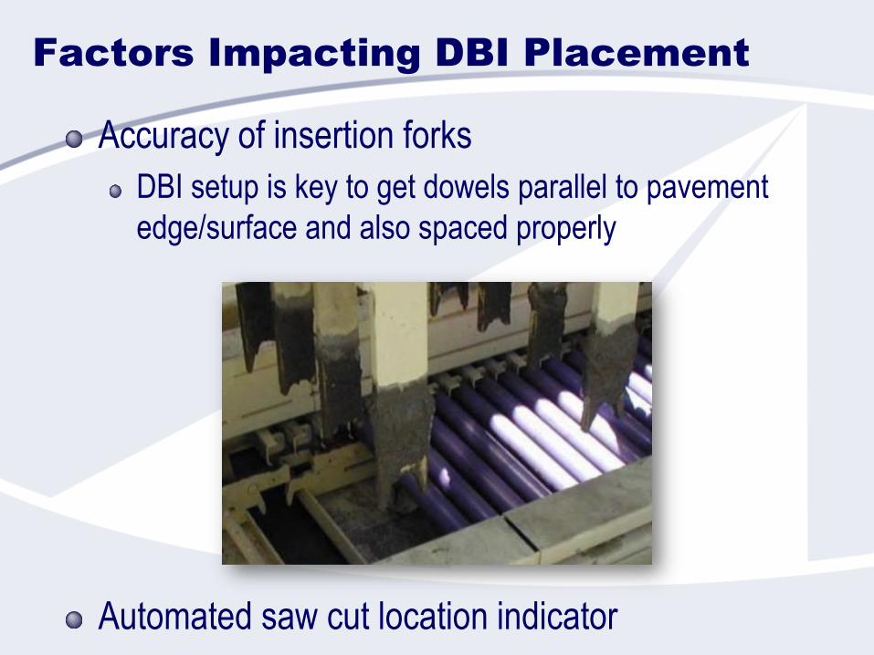
Factors Impacting DBI Placement
Accuracy of insertion forks
DBI setup is key to get dowels parallel to pavement
edge/surface and also spaced properly
Automated saw cut location indicator
Placement Factors Impacting Alignment/Location
Baskets
Basket rigidity and design
wire sizes, leg shapes (“J” vs “A”/”V”/”U”)
Basket stability – pins, support layer, shipping wires, etc.
See FHWA Tech Brief: Dowel Basket Anchoring Methods – May 2016
Concrete placement and paving processes
Placed relative to top of base
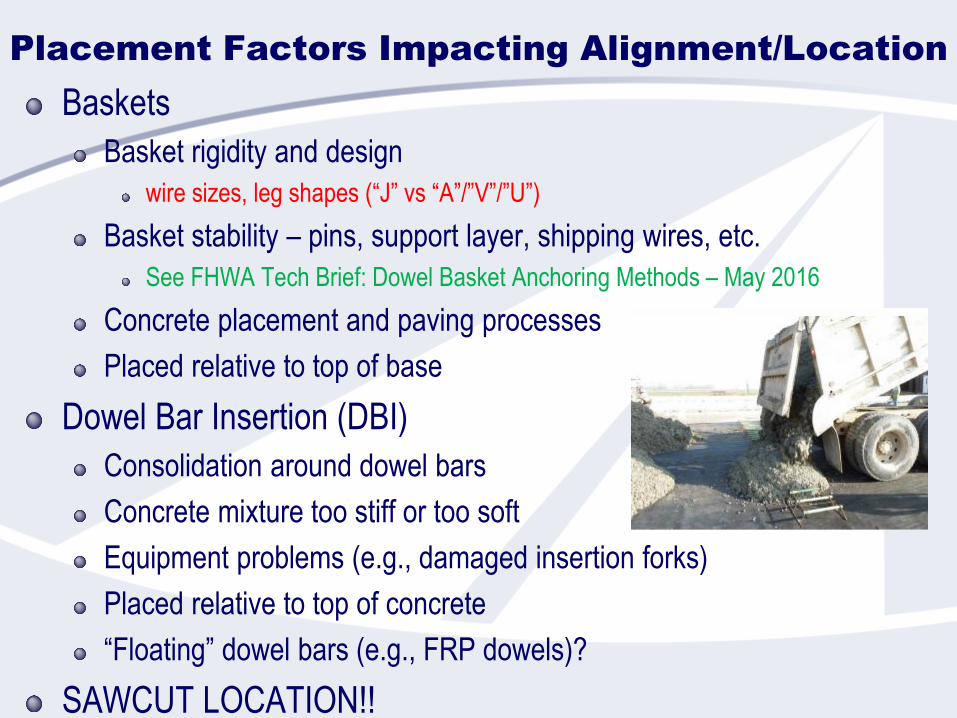
Dowel Bar Insertion (DBI)
Consolidation around dowel bars
Concrete mixture too stiff or too soft
Equipment problems (e.g., damaged insertion forks)
Placed relative to top of concrete
“Floating” dowel bars (e.g., FRP dowels)?
SAWCUT LOCATION!!
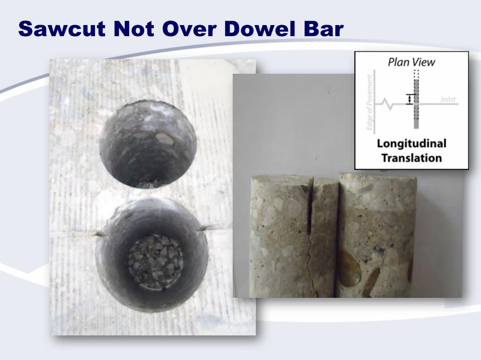
Sawcut Not Over Dowel Bar
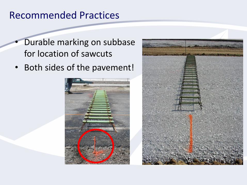
Recommended Practices
• Durable marking on subbasefor location of sawcuts
• Both sides of the pavement!
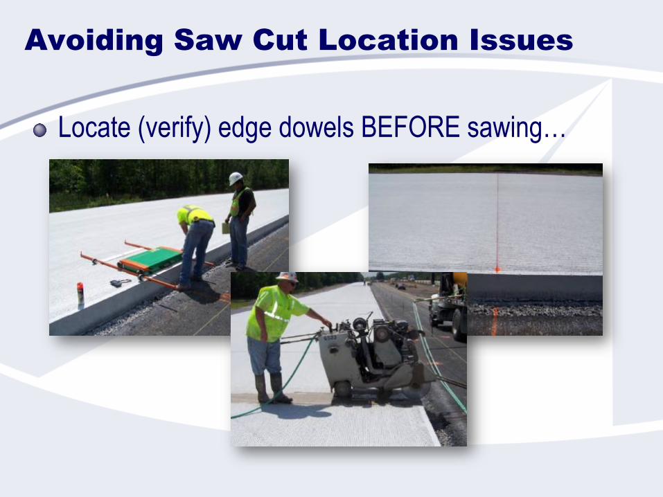
Avoiding Saw Cut Location Issues
Locate (verify) edge dowels BEFORE sawing…
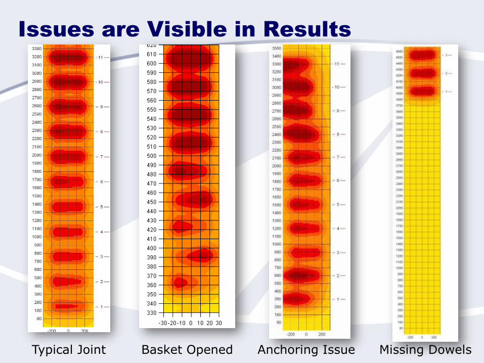
Issues are Visible in Results
Typical Joint Basket Opened Anchoring Issue Missing Dowels
Potential Impacts of
Misalignment/Mislocation
on Pavement Performance
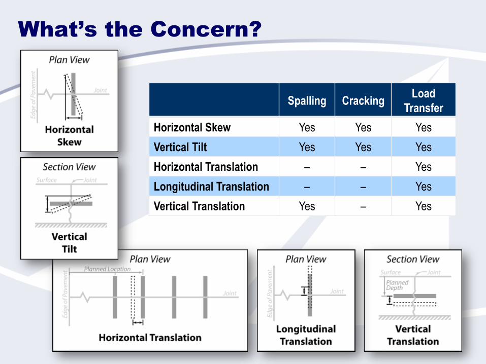
What’s the Concern?
Spalling CrackingLoad
Transfer
Horizontal Skew Yes Yes Yes
Vertical Tilt Yes Yes Yes
Horizontal Translation – – Yes
Longitudinal Translation – – Yes
Vertical Translation Yes – Yes
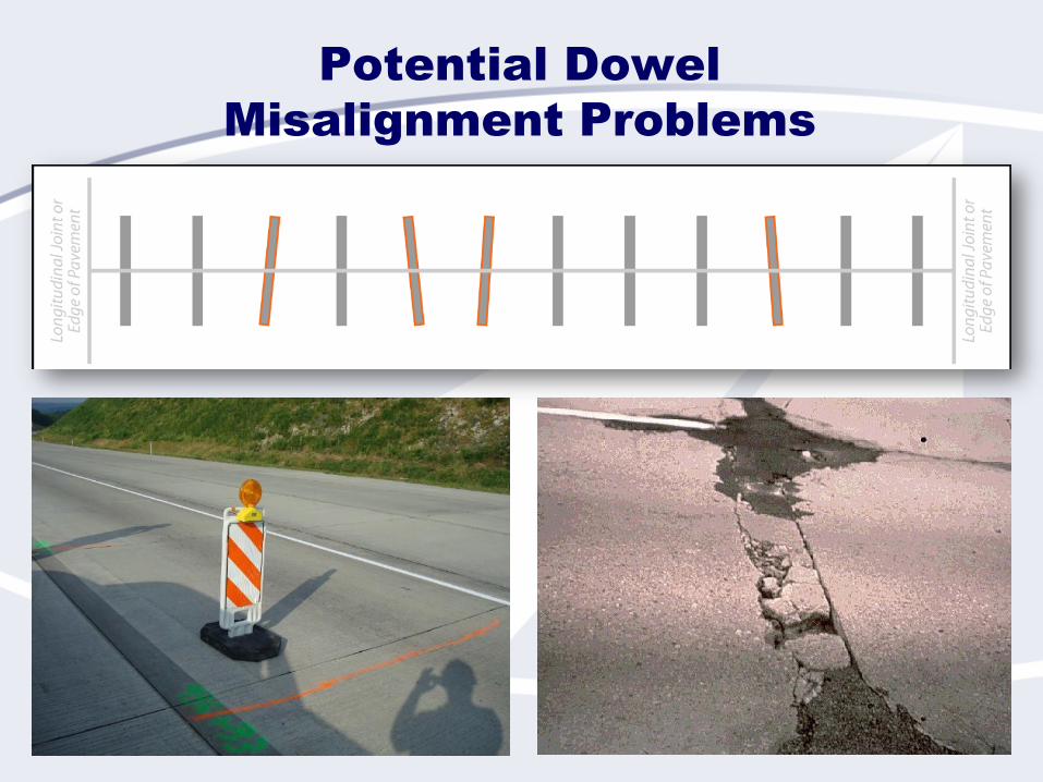
Potential Dowel
Misalignment Problems
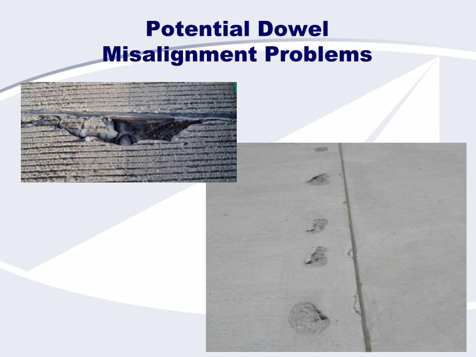
Potential Dowel
Misalignment Problems

Misalignment and
Mislocation Thresholds
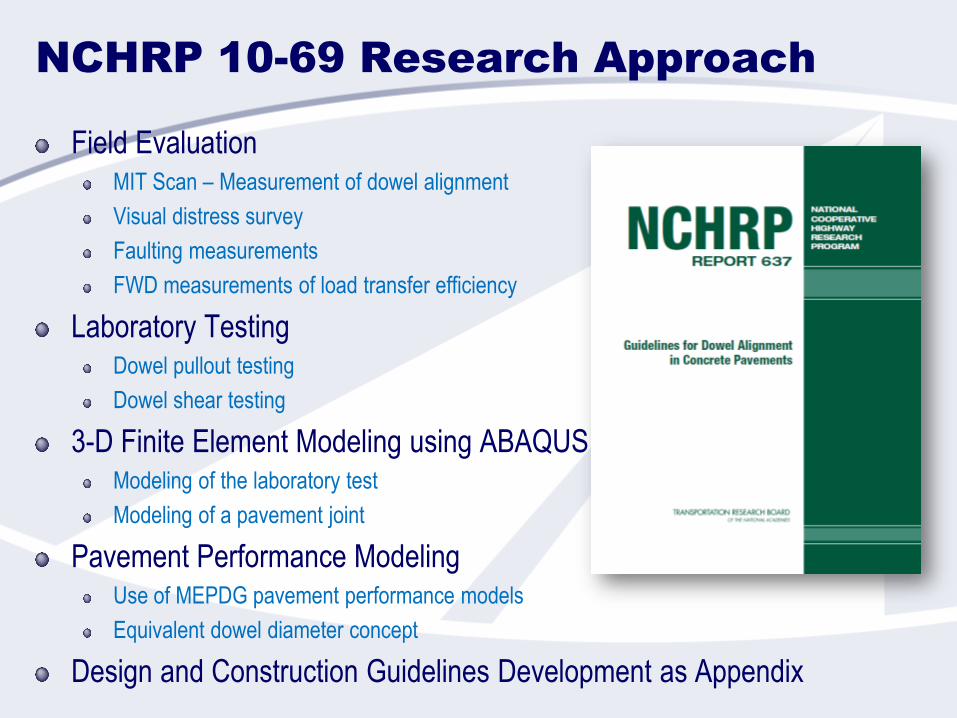
NCHRP 10-69 Research Approach
Field EvaluationMIT Scan – Measurement of dowel alignment
Visual distress survey
Faulting measurements
FWD measurements of load transfer efficiency
Laboratory TestingDowel pullout testing
Dowel shear testing
3-D Finite Element Modeling using ABAQUSModeling of the laboratory test
Modeling of a pavement joint
Pavement Performance ModelingUse of MEPDG pavement performance models
Equivalent dowel diameter concept
Design and Construction Guidelines Development as Appendix
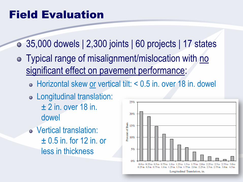
Field Evaluation
35,000 dowels | 2,300 joints | 60 projects | 17 states
Typical range of misalignment/mislocation with no
significant effect on pavement performance:
Horizontal skew or vertical tilt: < 0.5 in. over 18 in. dowel
Longitudinal translation:
± 2 in. over 18 in.
dowel
Vertical translation:
± 0.5 in. for 12 in. or
less in thickness
Laboratory Testing
64 single-dowel misalignment/mislocation tests
Two-part test:
Pull-out to simulate joint opening
Shear test to simulate loading on damaged system
Results:
Dowel lubrication significantly affects pullout force
Dowel rotation as extreme as 2 in. per 18 in. dowel does not affect
shear capacity
Reduction in concrete cover from 3.25 in. to 1.25 in. causes severe
reduction in ultimate shear capacity
Reduction in dowel embedment length to 3 in. and less significantly
reduces shear capacity
Combinations of misalignment and mislocation have a
compounding effect on shear performance
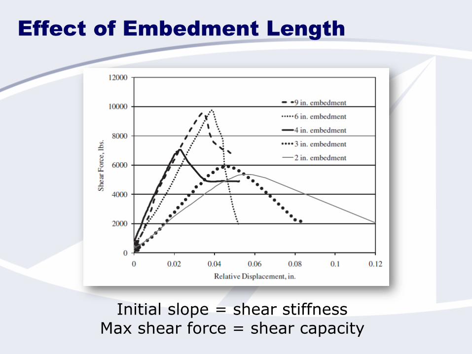
Effect of Embedment Length
Initial slope = shear stiffnessMax shear force = shear capacity
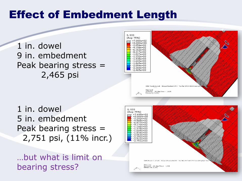
Effect of Embedment Length
1 in. dowel9 in. embedmentPeak bearing stress =
2,465 psi
1 in. dowel5 in. embedmentPeak bearing stress =
2,751 psi, (11% incr.)
…but what is limit on bearing stress?
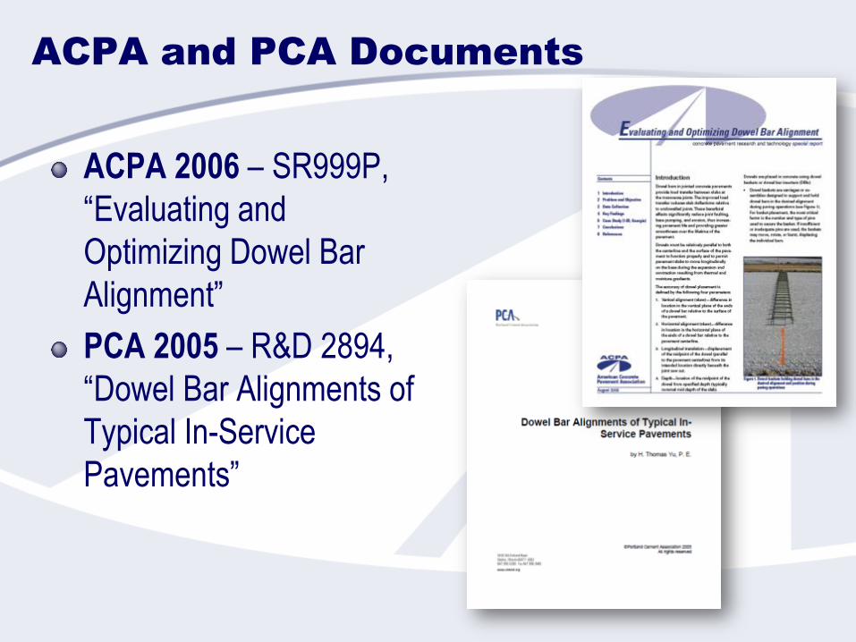
ACPA and PCA Documents
ACPA 2006 – SR999P,
“Evaluating and
Optimizing Dowel Bar
Alignment”
PCA 2005 – R&D 2894,
“Dowel Bar Alignments of
Typical In-Service
Pavements”
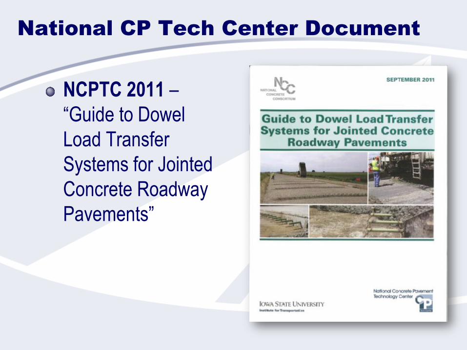
National CP Tech Center Document
NCPTC 2011 –
“Guide to Dowel
Load Transfer
Systems for Jointed
Concrete Roadway
Pavements”
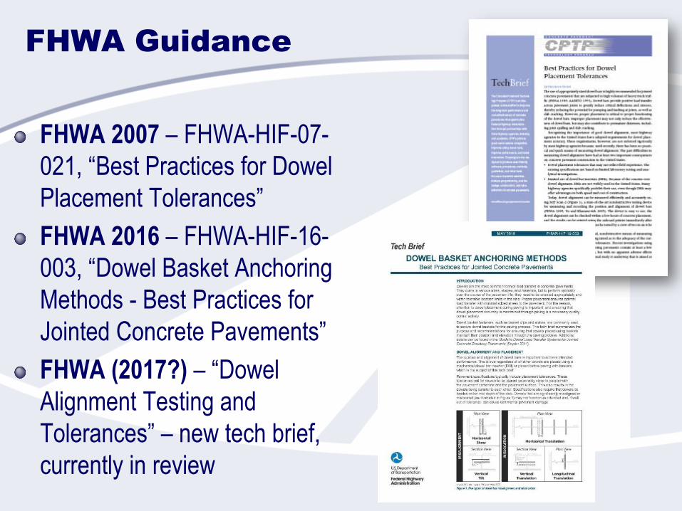
FHWA Guidance
FHWA 2007 – FHWA-HIF-07-
021, “Best Practices for Dowel
Placement Tolerances”
FHWA 2016 – FHWA-HIF-16-
003, “Dowel Basket Anchoring
Methods - Best Practices for
Jointed Concrete Pavements”
FHWA (2017?) – “Dowel
Alignment Testing and
Tolerances” – new tech brief,
currently in review
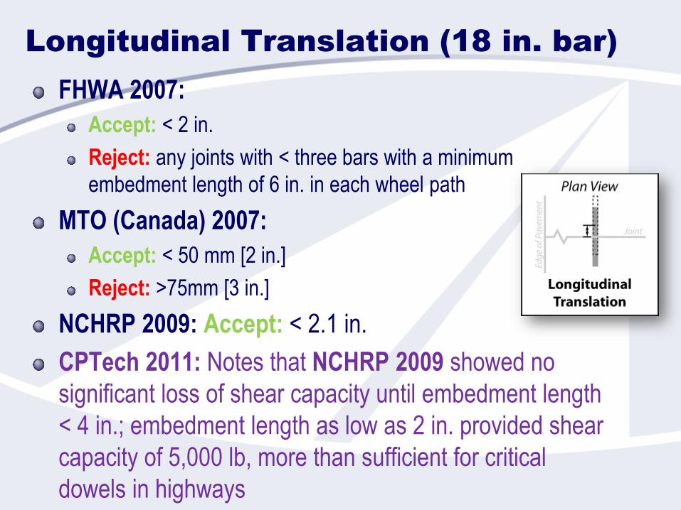
Longitudinal Translation (18 in. bar)
FHWA 2007:
Accept: < 2 in.
Reject: any joints with < three bars with a minimum
embedment length of 6 in. in each wheel path
MTO (Canada) 2007:
Accept: < 50 mm [2 in.]
Reject: >75mm [3 in.]
NCHRP 2009: Accept: < 2.1 in.
CPTech 2011: Notes that NCHRP 2009 showed no
significant loss of shear capacity until embedment length
< 4 in.; embedment length as low as 2 in. provided shear
capacity of 5,000 lb, more than sufficient for critical
dowels in highways
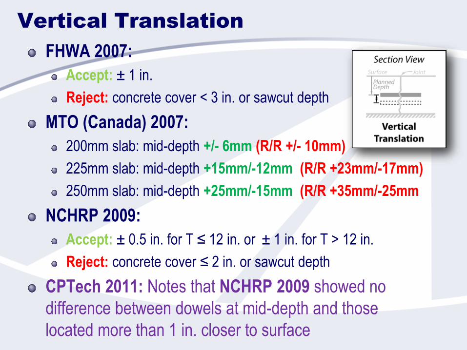
Vertical Translation
FHWA 2007:
Accept: ± 1 in.
Reject: concrete cover < 3 in. or sawcut depth
MTO (Canada) 2007:
200mm slab: mid-depth +/- 6mm (R/R +/- 10mm)
225mm slab: mid-depth +15mm/-12mm (R/R +23mm/-17mm)
250mm slab: mid-depth +25mm/-15mm (R/R +35mm/-25mm
NCHRP 2009:
Accept: ± 0.5 in. for T ≤ 12 in. or ± 1 in. for T > 12 in.
Reject: concrete cover ≤ 2 in. or sawcut depth
CPTech 2011: Notes that NCHRP 2009 showed no
difference between dowels at mid-depth and those
located more than 1 in. closer to surface
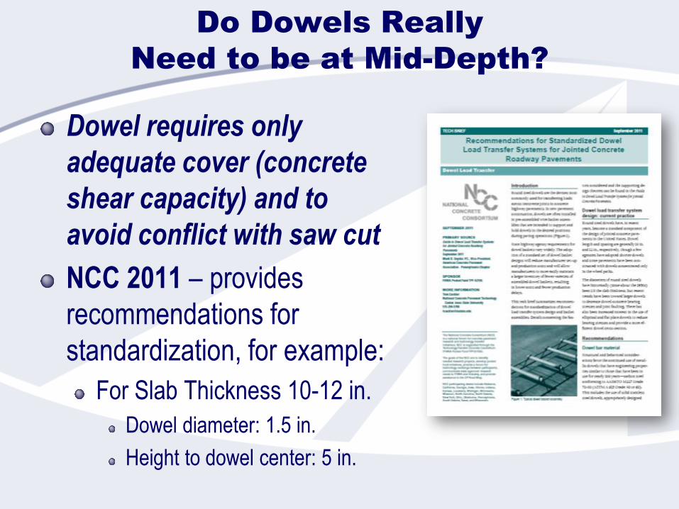
Do Dowels Really
Need to be at Mid-Depth?
Dowel requires only
adequate cover (concrete
shear capacity) and to
avoid conflict with saw cut
NCC 2011 – provides
recommendations for
standardization, for example:
For Slab Thickness 10-12 in.
Dowel diameter: 1.5 in.
Height to dowel center: 5 in.
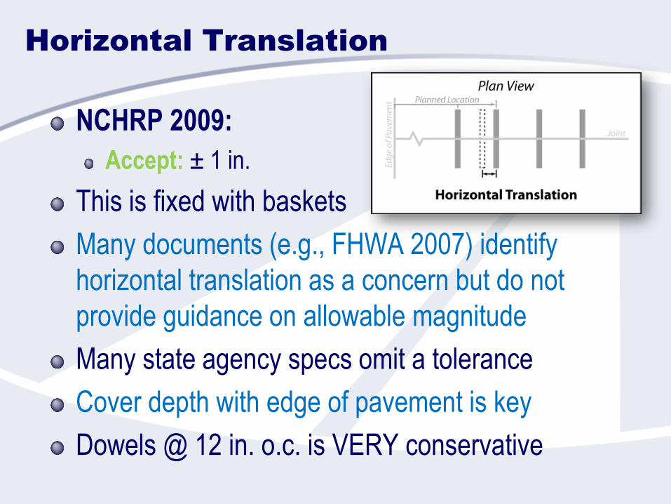
Horizontal Translation
NCHRP 2009:
Accept: ± 1 in.
This is fixed with baskets
Many documents (e.g., FHWA 2007) identify
horizontal translation as a concern but do not
provide guidance on allowable magnitude
Many state agency specs omit a tolerance
Cover depth with edge of pavement is key
Dowels @ 12 in. o.c. is VERY conservative
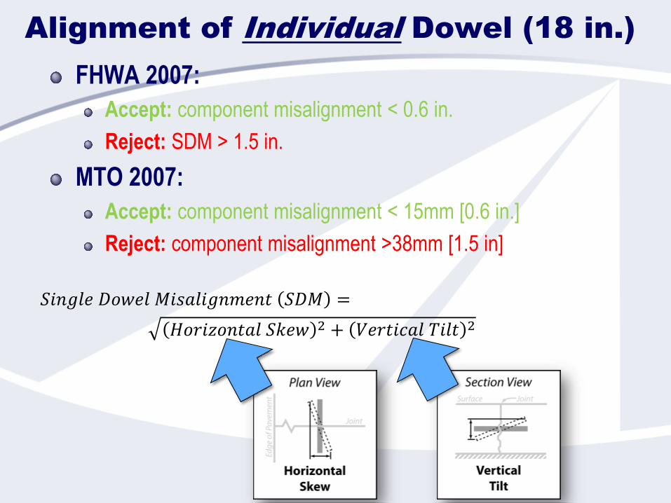
Alignment of Individual Dowel (18 in.)
FHWA 2007:
Accept: component misalignment < 0.6 in.
Reject: SDM > 1.5 in.
MTO 2007:
Accept: component misalignment < 15mm [0.6 in.]
Reject: component misalignment >38mm [1.5 in]
𝐻𝑜𝑟𝑖𝑧𝑜𝑛𝑡𝑎𝑙 𝑆𝑘𝑒𝑤 2 + 𝑉𝑒𝑟𝑡𝑖𝑐𝑎𝑙 𝑇𝑖𝑙𝑡 2
𝑆𝑖𝑛𝑔𝑙𝑒 𝐷𝑜𝑤𝑒𝑙 𝑀𝑖𝑠𝑎𝑙𝑖𝑔𝑛𝑚𝑒𝑛𝑡 𝑆𝐷𝑀 =
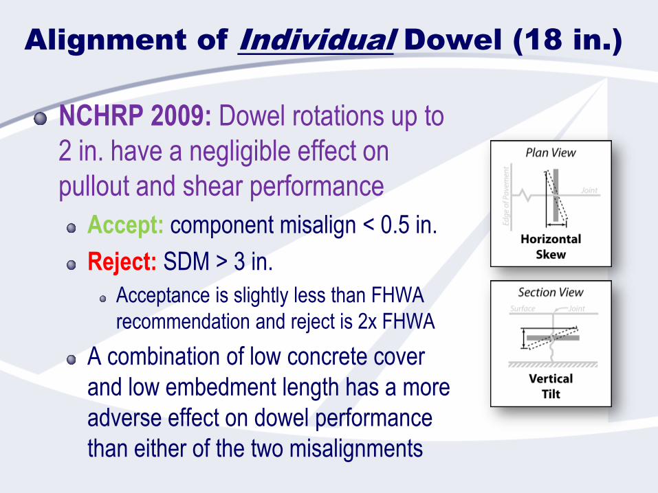
Alignment of Individual Dowel (18 in.)
NCHRP 2009: Dowel rotations up to
2 in. have a negligible effect on
pullout and shear performance
Accept: component misalign < 0.5 in.
Reject: SDM > 3 in.
Acceptance is slightly less than FHWA
recommendation and reject is 2x FHWA
A combination of low concrete cover
and low embedment length has a more
adverse effect on dowel performance
than either of the two misalignments
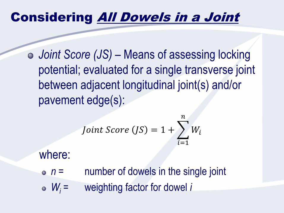
Considering All Dowels in a Joint
Joint Score (JS) – Means of assessing locking
potential; evaluated for a single transverse joint
between adjacent longitudinal joint(s) and/or
pavement edge(s):
where:
n = number of dowels in the single joint
Wi = weighting factor for dowel i
𝐽𝑜𝑖𝑛𝑡 𝑆𝑐𝑜𝑟𝑒 𝐽𝑆 = 1 +
𝑖=1
𝑛
𝑊𝑖
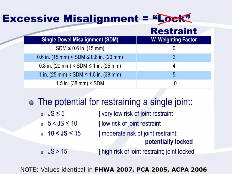
Excessive Misalignment = “Lock”
The potential for restraining a single joint:JS ≤ 5 | very low risk of joint restraint
5 < JS ≤ 10 | low risk of joint restraint
10 < JS ≤ 15 | moderate risk of joint restraint;
potentially locked
JS > 15 | high risk of joint restraint; joint locked
NOTE: Values identical in FHWA 2007, PCA 2005, ACPA 2006
Restraint
Single Dowel Misalignment (SDM) W, Weighting Factor
SDM ≤ 0.6 in. (15 mm) 0
0.6 in. (15 mm) < SDM ≤ 0.8 in. (20 mm) 2
0.8 in. (20 mm) < SDM ≤ 1 in. (25 mm) 4
1 in. (25 mm) < SDM ≤ 1.5 in. (38 mm) 5
1.5 in. (38 mm) < SDM 10
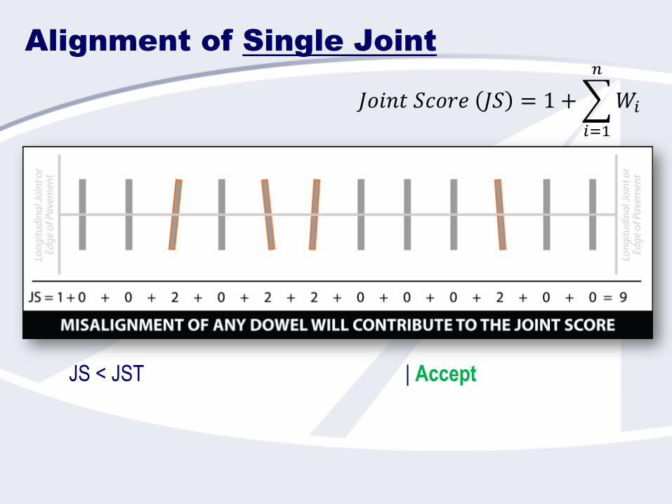
Alignment of Single Joint
JS < JST | Accept
𝐽𝑜𝑖𝑛𝑡 𝑆𝑐𝑜𝑟𝑒 𝐽𝑆 = 1 +
𝑖=1
𝑛
𝑊𝑖
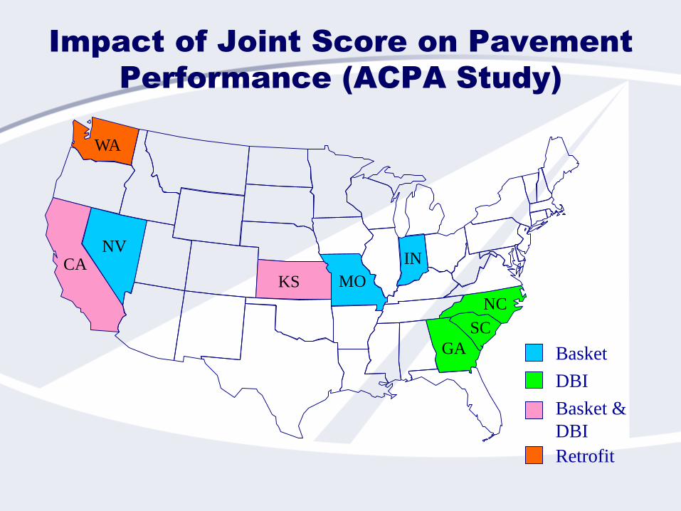
Impact of Joint Score on Pavement
Performance (ACPA Study)
Basket
DBI
Basket &
DBI
WA
NV
MOKS
IN
GA
NC
Retrofit
SC
CA
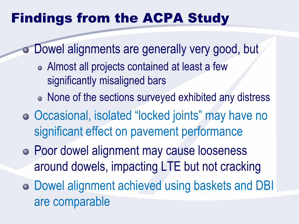
Findings from the ACPA Study
Dowel alignments are generally very good, but
Almost all projects contained at least a few
significantly misaligned bars
None of the sections surveyed exhibited any distress
Occasional, isolated “locked joints” may have no
significant effect on pavement performance
Poor dowel alignment may cause looseness
around dowels, impacting LTE but not cracking
Dowel alignment achieved using baskets and DBI
are comparable
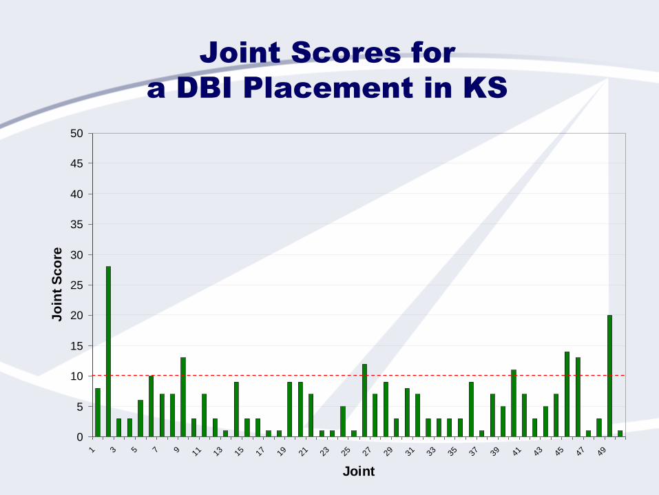
Joint Scores for
a DBI Placement in KS
0
5
10
15
20
25
30
35
40
45
50
1 3 5 7 9 11
13
15
17
19
21
23
25
27
29
31
33
35
37
39
41
43
45
47
49
Joint
Jo
int
Sc
ore
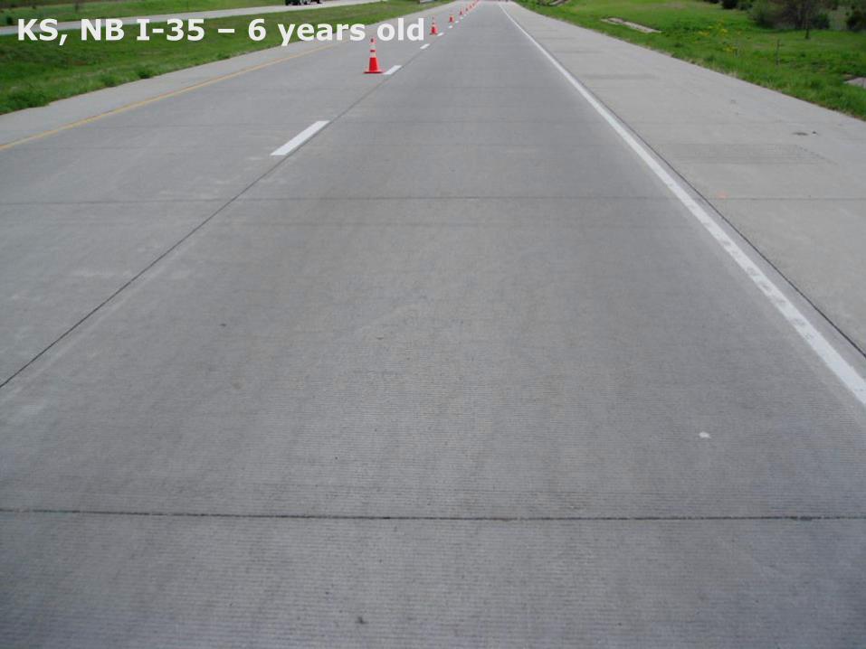
KS, NB I-35 – 6 years old
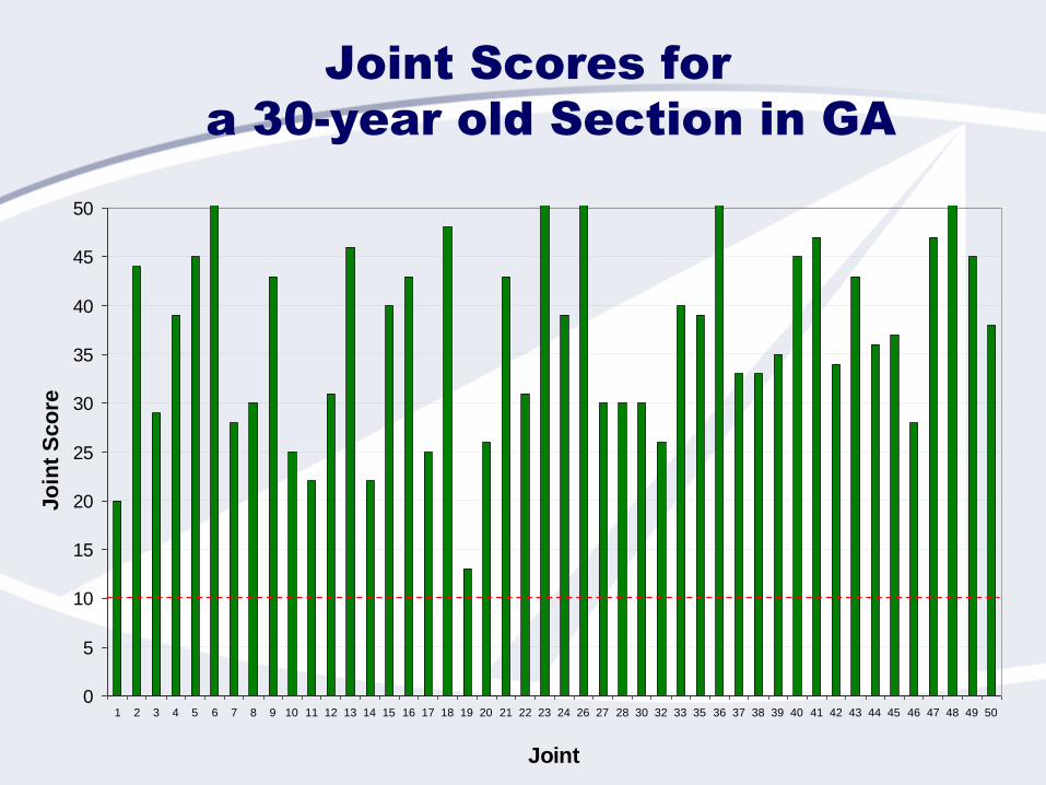
Joint Scores for
a 30-year old Section in GA
0
5
10
15
20
25
30
35
40
45
50
1 2 3 4 5 6 7 8 9 10 11 12 13 14 15 16 17 18 19 20 21 22 23 24 26 27 28 30 32 33 35 36 37 38 39 40 41 42 43 44 45 46 47 48 49 50
Joint
Jo
int
Sco
re
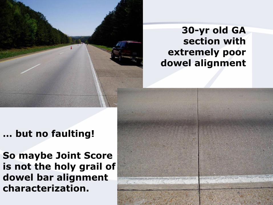
30-yr old GA section with
extremely poor dowel alignment
… but no faulting!
So maybe Joint Score is not the holy grail of dowel bar alignment characterization.
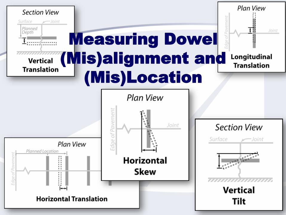
Measuring Dowel
(Mis)alignment and
(Mis)Location
49
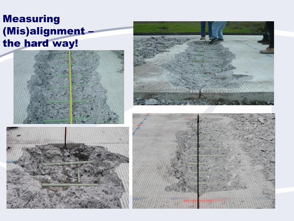
Measuring
(Mis)alignment –
the hard way!
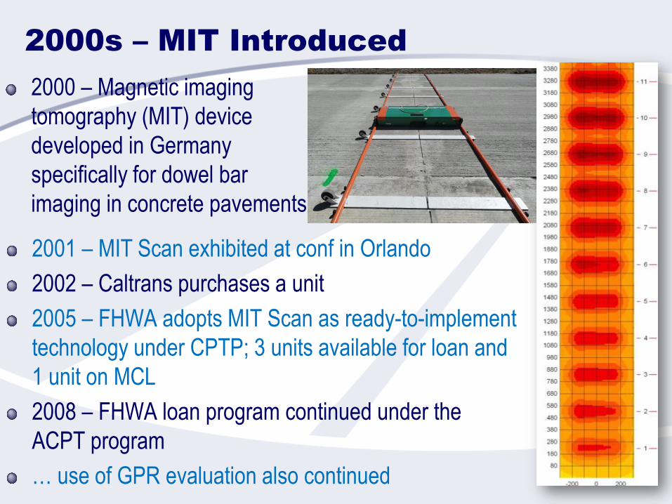
2000s – MIT Introduced
2000 – Magnetic imaging
tomography (MIT) device
developed in Germany
specifically for dowel bar
imaging in concrete pavements
2001 – MIT Scan exhibited at conf in Orlando
2002 – Caltrans purchases a unit
2005 – FHWA adopts MIT Scan as ready-to-implement
technology under CPTP; 3 units available for loan and
1 unit on MCL
2008 – FHWA loan program continued under the
ACPT program
… use of GPR evaluation also continued
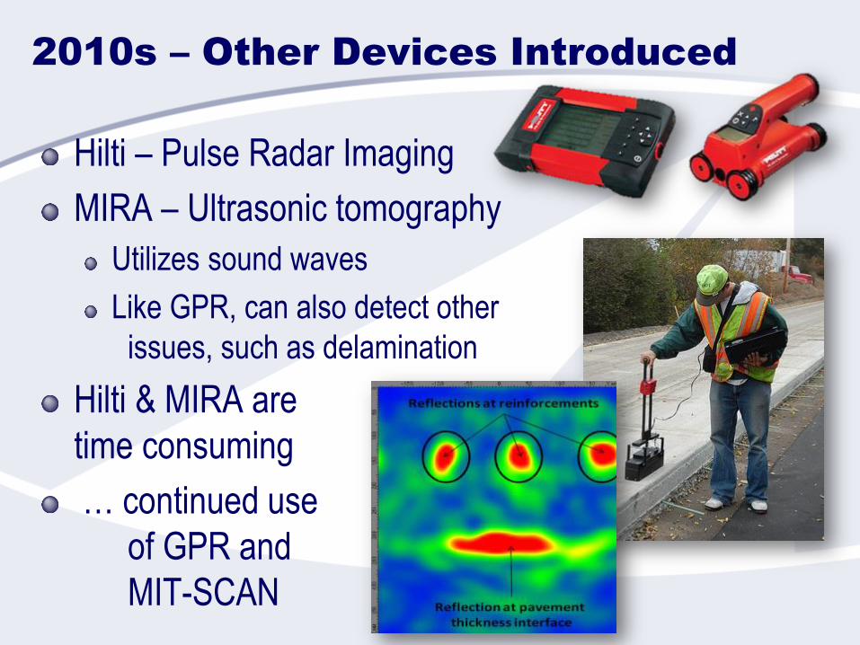
2010s – Other Devices Introduced
Hilti – Pulse Radar Imaging
MIRA – Ultrasonic tomography
Utilizes sound waves
Like GPR, can also detect other
issues, such as delamination
Hilti & MIRA are
time consuming
… continued use
of GPR and
MIT-SCAN
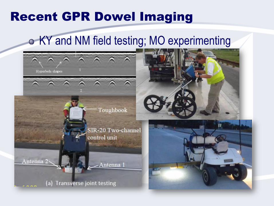
Recent GPR Dowel Imaging
KY and NM field testing; MO experimenting
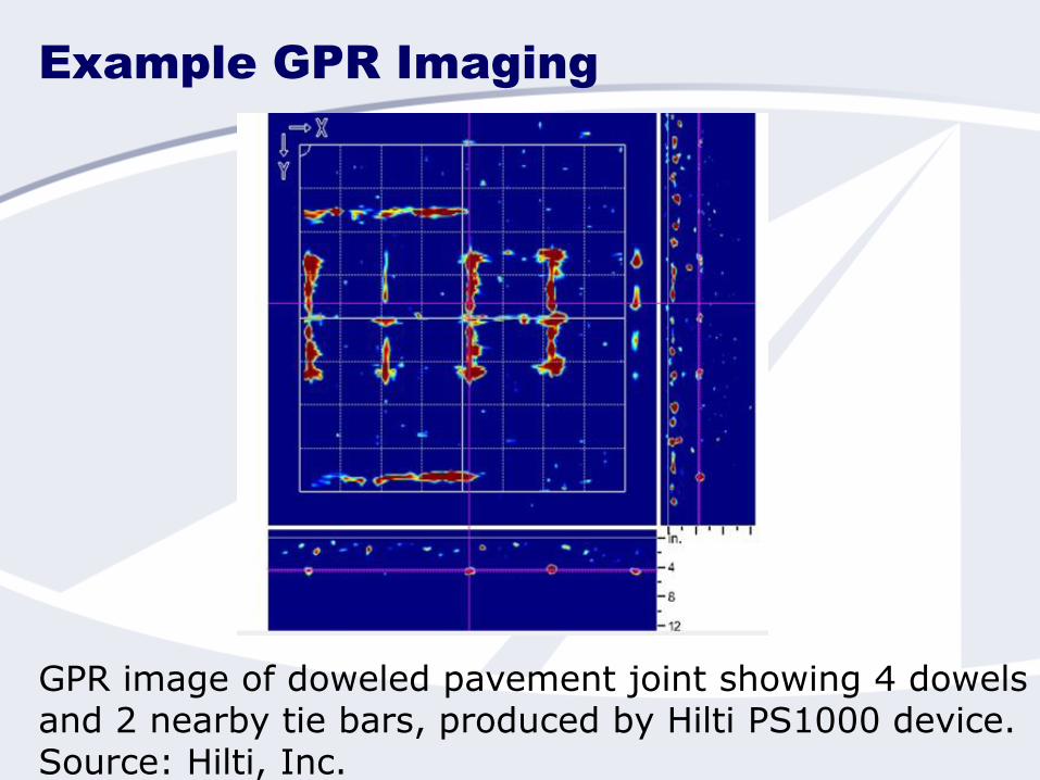
Example GPR Imaging
GPR image of doweled pavement joint showing 4 dowelsand 2 nearby tie bars, produced by Hilti PS1000 device. Source: Hilti, Inc.
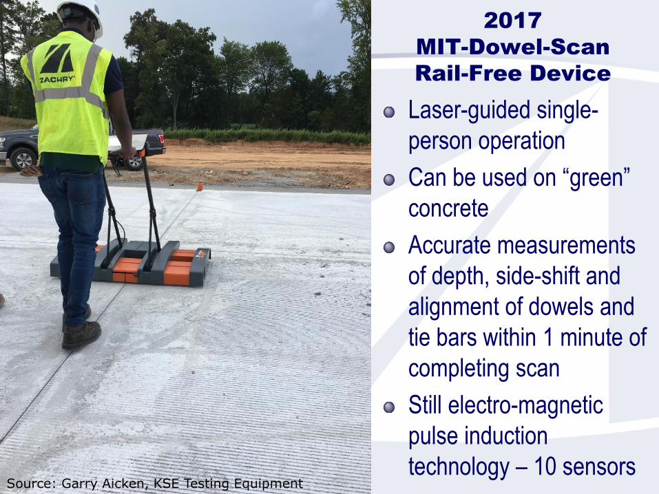
2017
MIT-Dowel-Scan
Rail-Free Device
Laser-guided single-
person operation
Can be used on “green”
concrete
Accurate measurements
of depth, side-shift and
alignment of dowels and
tie bars within 1 minute of
completing scan
Still electro-magnetic
pulse induction
technology – 10 sensorsSource: Garry Aicken, KSE Testing Equipment
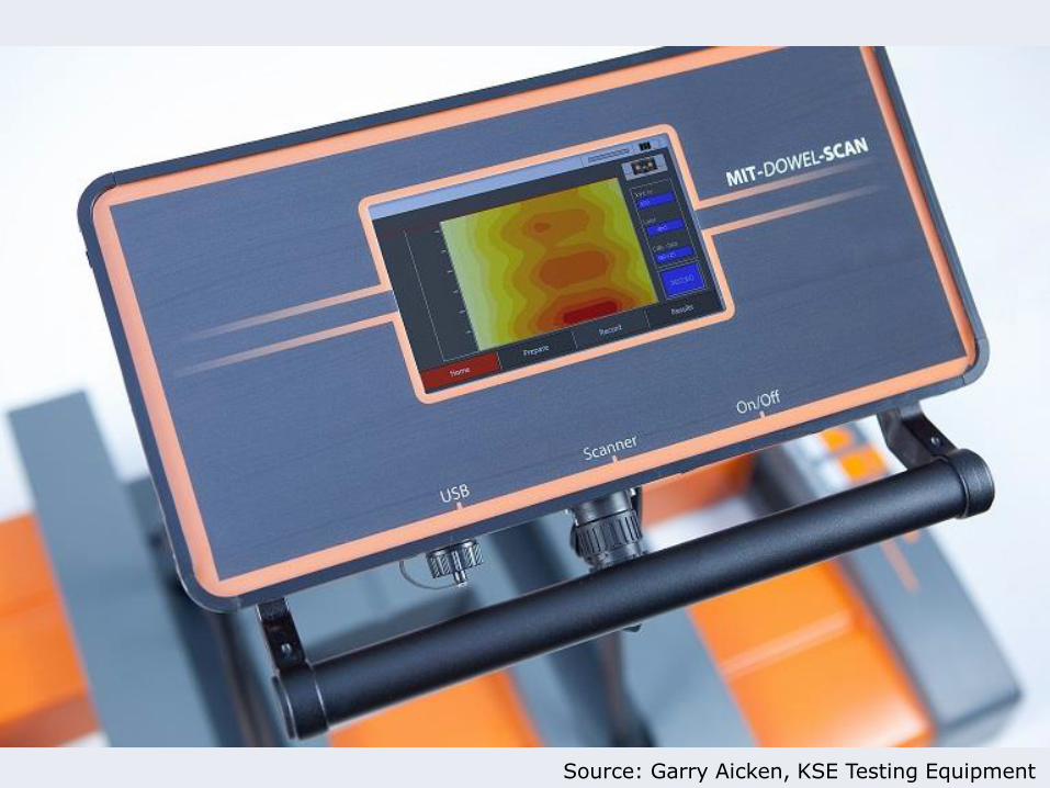
Source: Garry Aicken, KSE Testing Equipment
Where We Are Now …
Imaging technologies are being adopted and
improved rapidly
Guidance on their use is also evolving
Personal opinions:
Can always dig out or core, but not ideal
MIRA and Hilti devices are currently good for forensic work
but too labor intensive (for now) for production work
GPR can test joints quickly for production, can see
nonmetallic and nonmagnetic dowels, but accuracy may
be lower than MIT-Scan devices (for now)
MIT Scan2-BT is currently the most widely used device
Spec tolerances vary between devices!!
Concepts for Dowel
Alignment Specifications
The Goals
Provide indicators of adequate construction process control
(i.e., define unqualified acceptance levels).
Consider use of incentives/disincentives (PWL) to encourage good
process control.
Avoid conditions that are likely to result in reduced levels of
pavement performance or service life (i.e., define unqualified
rejection levels).
Provide better guidance on when expensive corrective actions
(i.e., remove and replace, etc.) are really necessary.
Simplify measurement/control process.
Basis for Alignment Criteria
Identify distresses and conditions that may result from
each type of misalignment/mislocation
Develop acceptance/action/rejection criteria based on
measures of misalignment/mislocation for individual
dowels or groups of dowels, as appropriate.
Criteria must recognize:
Target (acceptance) levels (easily achievable with good
practices)
Process correction levels (fails to meet target levels, but no
anticipated performance problems)
Corrective action levels (possible performance problems)
Example: Rotational Misalignment Limits
Distress Mechanisms
Dowel Groups: Restraint of Joint Function
Development of dominant joints
Sealant failure, infiltration of water and incompressibles
Load transfer system failure
Deep joint spalling, loss of load transfer, higher
deflections/stresses, reduced pavement life
Possible mid-panel cracking
Alignment Criteria
Dowel Groups: Control Restraint of Joint Function
PWL on Joint Score
Limit consecutive restrained joints (e.g., MARL < 60 ft)
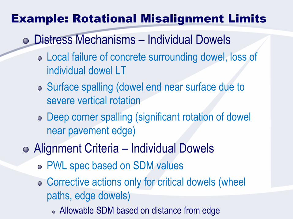
Example: Rotational Misalignment Limits
Distress Mechanisms – Individual Dowels
Local failure of concrete surrounding dowel, loss of
individual dowel LT
Surface spalling (dowel end near surface due to
severe vertical rotation
Deep corner spalling (significant rotation of dowel
near pavement edge)
Alignment Criteria – Individual Dowels
PWL spec based on SDM values
Corrective actions only for critical dowels (wheel
paths, edge dowels)
Allowable SDM based on distance from edge
Considering Measurement
Accuracy of Equipment
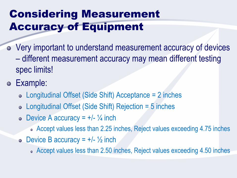
Very important to understand measurement accuracy of devices
– different measurement accuracy may mean different testing
spec limits!
Example:
Longitudinal Offset (Side Shift) Acceptance = 2 inches
Longitudinal Offset (Side Shift) Rejection = 5 inches
Device A accuracy = +/- ¼ inch
Accept values less than 2.25 inches, Reject values exceeding 4.75 inches
Device B accuracy = +/- ½ inch
Accept values less than 2.50 inches, Reject values exceeding 4.50 inches
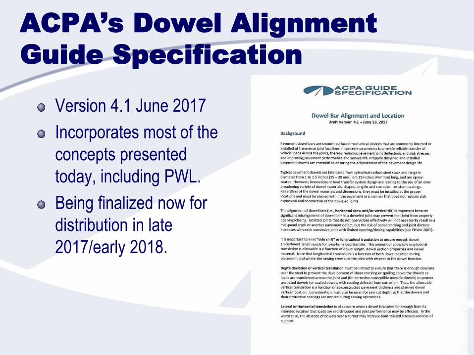
ACPA’s Dowel Alignment
Guide Specification
Version 4.1 June 2017
Incorporates most of the
concepts presented
today, including PWL.
Being finalized now for
distribution in late
2017/early 2018.
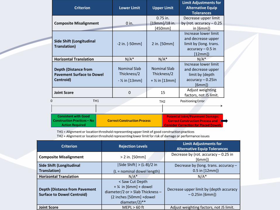
Criterion Lower Limit Upper LimitLimit Adjustments for
Alternative Equip Tolerances
Composite Misalignment 0 in.0.75 in.
[19mm]/18 in. [450mm]
Decrease upper limit by (rot. accuracy – 0.25
in [6mm])
Side Shift (Longitudinal Translation)
-2 in. [-50mm] 2 in. [50mm]
Increase lower limit and decrease upper limit by (long. trans.
accuracy – 0.5 in [12mm])
Horizontal Translation N/A* N/A* N/A*
Depth (Distance from Pavement Surface to Dowel Centroid)
Nominal Slab Thickness/2
- ½ in [13mm]
Nominal Slab Thickness/2
+ ½ in [13mm]
Increase lower limit and decrease upper
limit by (depth accuracy – 0.25in
[6mm])
Joint Score 0 15Adjust weighting
factors, not JS limit.
Criterion Rejection LevelsLimit Adjustments for
Alternative Equip Tolerances
Composite Misalignment > 2 in. [50mm]Decrease by (rot. accuracy – 0.25 in
[6mm])
Side Shift (Longitudinal Translation)
|Side Shift| > (L-8)/2 in
(L = nominal dowel length)
Decrease by (long. trans. accuracy –0.5 in [12mm])
Horizontal Translation N/A* N/A*
Depth (Distance from Pavement Surface to Dowel Centroid)
< Saw Cut Depth + ¼ in [6mm] + dowel
diameter/2 or > Slab Thickness –(2 inches [50mm] +dowel
diameter/2)**
Decrease upper limit by (depth accuracy – 0.25in [6mm])
Joint Score MEPL > 60 ft Adjust weighting factors, not JS limit.
Acknowledgments
Garry Aicken – KSE Testing Equipment
Sarah Bazey and Glenn Eder – JC/Simplex Supply and Manufacturing
Jagan Gudimettla – FHWA
Ron Guntert – Guntert & Zimmerman
Kyle Hoegh, Minnesota DOT
Lev Khazanovich, University of Pittsburgh
Shreenath Rao – Applied Research Associates
Brad Rister – Univ of KY
Nigel Parkes and Robert Rodden, PNA
Shiraz Tayabji – Advanced Concrete Pavement Consultancy, LLC
Jerry Voigt and Eric Ferrebee, ACPA
Dan Ye – Fugro Consultants
Tom Yu – FHWA
Peter Smith – The Fort Miller Company, Inc.

Next up: Placement and Joint
Spacing Considerations
Main Website | acpa.orgConcrete Wiki | wiki.acpa.org
App Library | apps.acpa.orgDesktop Software | software.acpa.org
Resources | resources.acpa.orgOn-Demand Training | ondemand.acpa.org
Live Online Training | webinars.acpa.orgYour Local Contact | local.acpa.org
0%
10%
20%
30%
40%
50%
60%
70%
80%
0 10 20 30 40 50
Traffic, million ESALs
Per
cen
t sl
ab
cra
ckin
g