Embed Size (px)
Citation preview

DESIGN AND ANALYSIS OF THE THERMAL CONTROL SYSTEM FOR SPACE TECHNOLOGY 5
David NeubergerSwales Aerospace Incorporated
Beltsville, Maryland
15th Annual Thermal and Fluids Analysis WorkshopPasadena, California
August 30th – September 3rd, 2004

ST-5 Mission Concept
“The ST5 Project shall design, develop, integrate, test and
operate three {one} full service spacecraft, each with a mass less
than 25kg, through the use of breakthrough technologies. ”
“The ST5 project shall demonstrate the ability to
achieve accurate, research-quality scientific
measurements utilizing a nanosatellite with a mass
less than 25 kg. ”
“The ST5 project shall execute the design, development, test
and operation of multiple spacecraft to act as a single constellation rather than as
individual elements. ”
Micro-Satellite Design and Build
Research-Quality Spacecraft
Constellation Mission
Space Technology 5 is NASA’s pathfinder for highly capable, low-cost small spacecraft, miniaturized
subsystems, and constellation mission operations.

ST-5 Mission Summary
• Full Functional Autonomous Spacecraft with Integrated Technology• Science Grade Magnetic Sensitivity (~ 1 nT)• Mass: ……..…. 25Kg• Size: ………….. Diameter ~ 53 cm (Solar panel peak-to-peak)
Height ~48 cm (Antenna tip to antenna tip)• Power: ……….. ~20-25W at 9-10V
~7-9 Ah Battery• Uplink: ………. @ 1Kbps / Downlink: @1Kbps or 100Kbps (X-Band)• Data Storage: .. 20 Mbyte • Spin Stabilized at Separation (~25 RPM After Deployments)• Deployments: Magnetometer• Radiation Tolerant: 100 Krad-Si TID
• Launch Vehicle: Pegasus XL• Launch Location: Vandenberg AFB, Lompoc, CA• Orbital Injection: Sun-Synchronous Polar Elliptical Orbit (300km x 4500km)• Three Spacecraft carried on Spacecraft Support Structure as Prime Payload
• 3-Spacecraft Constellation• 3-Month Design Life• 136 min Orbit Period• 10-30 Minutes Ground Contact Three Times Per Day• Autonomous Constellation Management / “Lights Out” OperationsM
ISSION
LAUNCH
SPACECRAFT

Baseline Orbital Elements
Launch Timeframe: February-March 2006Launch Site: Vandenberg AFB, Lompoc, CAMission Duration: 90 daysEclipses: None due to earth shadow, March 29
eclipses on 2 - 3 orbits due to moon shadowPerigee: 300 kmApogee: 4500 kmInclination: 105.6 deg (sun synchronous)Period: 136 minNumber of orbits/day: about 10.5RAAN: 42 deg or so for Feb 15 launch, increasing 1
deg/day for launch later in launch window (full sun 6 AM - 6 PM)
Launch Argument of Perigee: 160 degRotation of Apsides: -1.2 deg/day (apogee rotates towards South
Pole)
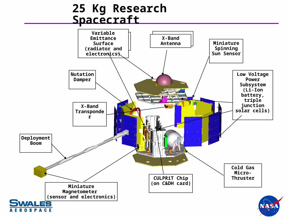
25 Kg Research Spacecraft
MiniatureMagnetometer
(sensor and electronics)
DeploymentBoom
Variable Emittance Surface (radiator and electronics)
X-Band Transponder
Miniature Spinning
Sun Sensor
CULPRiT Chip(on C&DH card)
Low Voltage Power
Subsystem (Li-Ion battery,
triple junction solar cells)
Cold Gas Micro-Thruster
Nutation Damper
X-Band Antenna

ST-5 Spacecraft• Developed by GSFC
• Description
o Built within tight volume and mass constraintso Low-power and low voltageo ~53 cm x 48 cmo Integral card cage structure (for C&DH, PSE)
• Key performance parameters
o Mass less than 25 kgo Spacecraft-induced magnetic field effects as measured at the magnetometer sensor
location less than 10 nT (d.c.), 5 nT (a.c.)
• Ground Testing
o Component testing per ST5-495-007 (including magnetics)o FLATSAT for electrical integration of engineering modelso Spacecraft-level functional and environmental testing (including magnetics)
• Flight testing
o Operations of the spacecraft during the 90-day mission (including magnetometer measurement of s/c magnetic field)
• Future applicability: s/c useful as-is or re-use components

Spacecraft Layout (Deployed)
NutationDamperMag Electronics
C&DH
Battery
PropellantTank
PSE
VEC Controller #1
Sun Sensor
VEC Controller #2
Transponder Electronics
HPA
VEC Radiator #2
X-Band Antenna
73.1 cm
3.0 cm
50.8cm
Mag Boom
Mag Sensor
+Zsc+Xsc
+Ysc+Xsc
+Zsc
VEC Radiator #1
28.6 cm
Thruster{Nozzle Exit}
TCE
PressureTransducer
DiplexerThruster
X-BandAntenna
10.5 cm
27.0 cm
10.5 cm

Spacecraft Thermal Design (1 of 3)• Sizing Conditions
o The thermal design was established with the assumed condition that the spacecraft is spinning with the spin axis of the spacecraft normal to the ecliptic plane ±5°.
o The thermal design was sized assuming a spacecraft internal heat dissipation of ~20 watts for hot case and ~13 watts for cold case.
o Electrical power is subtracted off solar arrays.
o An electrically conductive coating with a high emittance is used for the radiators, e.g. NS43C.
o Black paint/anodize is used to provide a high emittance interior.
o Heat in and out dominated by solar energy absorbed by and radiated from body-mounted solar array panels; robust design.
o Highest possible apogee assumed for cold case, lowest possible apogee assumed for hot case.
• The ST-5 spacecraft TCS will utilize passive thermal control techniques (coatings, thermal conductors and isolators, insulation blankets, etc)

Spacecraft Thermal Design (2 of 3)• Most components are mounted to the interior of the top and
bottom deckso VEC ECUs and the TCE are mounted to the side of the card cage
o Nutation Damper is mounted to sidewall of spacecraft
• Multi-Layer Insulationo The gaps between adjacent solar array panels and the panels and the
spacecraft will be closed out using multi-layer insulation.
o A 2 layer Kapton “skirt” will be used around the base of the X-Band Antenna.
o The top and bottom decks will be covered with MLI on the external surfaces with a window cutout for radiators
o The Magnetometer Sensor Head will be wrapped with MLI.
o The rigid boom segments and root adapter will be wrapped with MLI.
o The battery will be wrapped with MLI on five sides and a low e film on the sixth side (facing the deck).

Spacecraft Thermal Design (3 of 3)• To minimize sources of heat loss/gain, some components will be
conductively isolated.
o VEC Radiators and the X-Band antenna will be isolated from the spacecraft using G10 standoffs
o The eight solar array panels will be conductively isolated from spacecraft using low conductivity mounting bracket, but radiatively coupled to spacecraft using a high emittance coating on sidewall (substrate already has a high emittance)
o The Magnetometer boom will be conductively isolated from the spacecraft and the sensor.
o The battery has been designed to be conductively isolated from the spacecraft.
• Other methods are used to increase conduction:
o Nusil and Teflon will be used for the High Power Amplifier and Transponder
o PSE and C&DH cards are heat sunk to the cardcage using a wedgelok along the right and left edges.
o Relatively large bolts are used to provide good contact conductance at bolted interface between the cage and the decks.

Thermal Analyses Modeling Philosophy
• Orbit parameters and operational scenarios were provided by the Project.
o 7 on orbit cases
o 7 launch cases
• How Design Margin is Implemented
o Use conventional conservative hot and cold case modeling assumptions to overestimate the predicted temperature extremes.
o Qualify components 10°C beyond their design limits.
o Incorporate additional design margin by keeping predicts at least 5°C from design limits, which results in at least 15°C margin on predicts.
• Due to swings in temperatures, multiple runs are completed in Sinda until a quasi-steady state is achieved.
o Temperature predicts represent max and min temperatures for various cases.
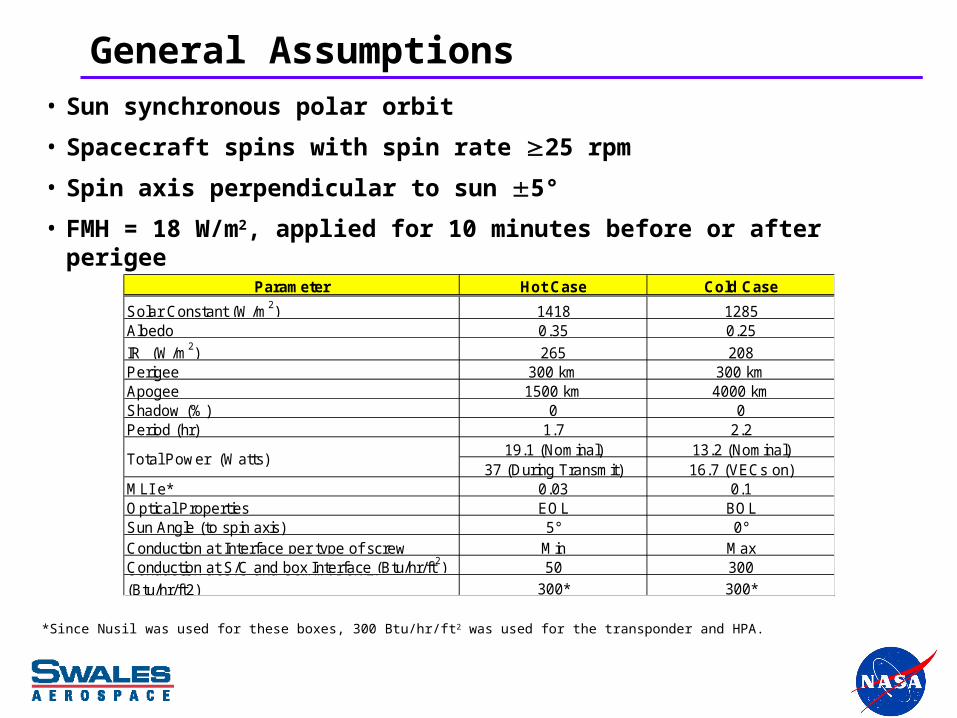
General Assumptions• Sun synchronous polar orbit
• Spacecraft spins with spin rate 25 rpm
• Spin axis perpendicular to sun 5°
• FMH = 18 W/m2, applied for 10 minutes before or after perigee
*Since Nusil was used for these boxes, 300 Btu/hr/ft2 was used for the transponder and HPA.
Parameter Hot Case Cold Case
Solar Constant (W/m2) 1418 1285Albedo 0.35 0.25
IR (W/m2) 265 208Perigee 300 km 300 kmApogee 1500 km 4000 kmShadow (%) 0 0Period (hr) 1.7 2.2
19.1 (Nominal) 13.2 (Nominal)37 (During Transmit) 16.7 (VECs on)
MLI e* 0.03 0.1Optical Properties EOL BOLSun Angle (to spin axis) 5° 0°Conduction at Interface per type of screw Min MaxConduction at S/C and box Interface (Btu/hr/ft2) 50 300Conduction at S/C and Comm. Box I/F (Btu/hr/ft2) 300* 300*
Total Power (Watts)

Material Properties
Material k(W/cm°C) Cp(J/Kg°C) LocationAluminum 6061 1.8 962 Decks, boxes, heat sink, etc.Aluminum A356 1.6 962 Card Cage AssemblyAluminum 7075 1.2 962 Magnetometer TangM55J 0.277 922 BoomM46J 0.201 922 Solar Array PanelsG-10 0.003 ** Antenna and VEC standoffsEccofoam SH-2 0.0002 ** Qual Helix AntennaUltem 7801 0.024 900 Snubbers, boom bracketCopper 3.9 418 Circuit boards, wiresNitrogen (Cv) N/A 733 PropellantTitanium 6Al-4V 0.073 648 Boom partsBeryllium Copper 1.3 418 Boom hingesStainless Steel 0.163 ** Bolts
** Arithmatic node or conduction path
BOL BOL EOL EOL
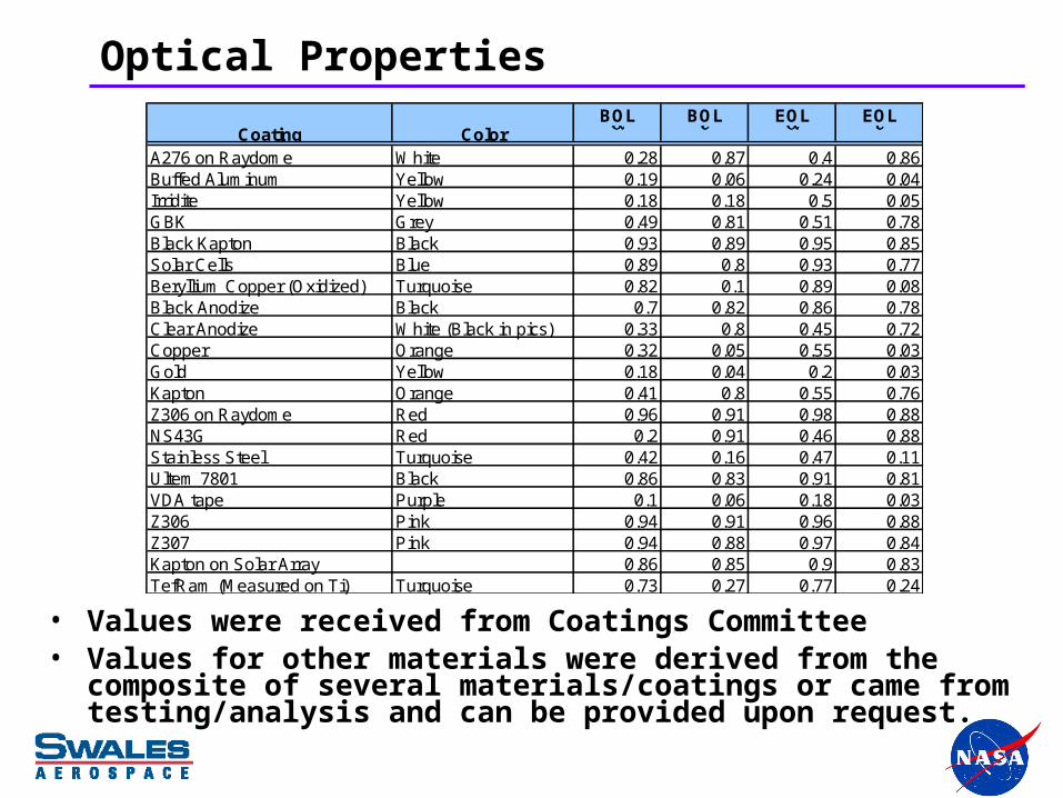
A276 on Raydome White 0.28 0.87 0.4 0.86Buffed Aluminum Yellow 0.19 0.06 0.24 0.04Irridite Yellow 0.18 0.18 0.5 0.05GBK Grey 0.49 0.81 0.51 0.78Black Kapton Black 0.93 0.89 0.95 0.85Solar Cells Blue 0.89 0.8 0.93 0.77Beryllium Copper (Oxidized) Turquoise 0.82 0.1 0.89 0.08Black Anodize Black 0.7 0.82 0.86 0.78Clear Anodize White (Black in pics) 0.33 0.8 0.45 0.72Copper Orange 0.32 0.05 0.55 0.03Gold Yellow 0.18 0.04 0.2 0.03Kapton Orange 0.41 0.8 0.55 0.76Z306 on Raydome Red 0.96 0.91 0.98 0.88NS43G Red 0.2 0.91 0.46 0.88Stainless Steel Turquoise 0.42 0.16 0.47 0.11Ultem 7801 Black 0.86 0.83 0.91 0.81VDA tape Purple 0.1 0.06 0.18 0.03Z306 Pink 0.94 0.91 0.96 0.88Z307 Pink 0.94 0.88 0.97 0.84Kapton on Solar Array 0.86 0.85 0.9 0.83TefRam (Measured on Ti) Turquoise 0.73 0.27 0.77 0.24
Coating Color
Optical Properties
• Values were received from Coatings Committee • Values for other materials were derived from the composite of
several materials/coatings or came from testing/analysis and can be provided upon request.

Cases
* 3 times per day
CaseApogee Altitude
Sun Angle (Relative to Spin Axis)
MLI ε*Un Regulated Bus Voltage
Powered On or Off
VEC MagEssential
BusTransmitter
Cold Safehold 4000km -25° 0.1 6.0 V Off Off On No
Hot Safehold 1500 km +25° 0.03 8.4 V Off Off On No
Cold Survival 4000km 0° 0.1 6.0 V Off Off On No
Cold Operational 4000km 0° 0.1 8.4 V On 1, Off 4 On On No
Hot Operational (short transmit)
1500 km + or – 5°0.03
8.4 V On On On 18 min*
Hot Operational (long transmit)
4000 km + or – 5°0.03
8.4 V On On On 30 min*

Power Assumptions
• Solar Array Power draw:
o The sum all component powers plus diodes is subtracted off solar array.
o Only valid as long as power is supplied by solar array only and/or battery is not charging. Power pulled off of array is limited to 24.4 Watts.
• Diodes on entire time.
• Essential bus on entire time.
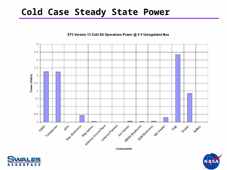
Cold Case Steady State Power

Hot Case Steady State Power

Model (1 of 2)

Model (2 of 2)

Predicts
-60
-40
-20
0
20
40
60
80
DS
S
Nu
t. D
amp
.
Mag
. E
U
Mag
. S
H+
CD
&H
Ele
c.
X-B
and
Tra
ns.
Dip
lexe
r B
ase
HP
A B
ase
Bat
tery
PS
E
On-Orbit Predicts
Op Limits
Non-Op Limits
<5°C Margin on Predicts
-60
-40
-20
0
20
40
60
80
DS
S
Nu
t. D
amp
.
Mag
. E
U
Mag
. S
H+
CD
&H
Ele
c.
X-B
and
Tra
ns.
Dip
lexe
r B
ase
HP
A B
ase
Bat
tery
PS
E
On-Orbit Predicts
Op Limits
Non-Op Limits
<5°C Margin on Predicts

Predicts
-80
-60
-40
-20
0
20
40
60
80
TC
E B
ase
pla
te
PT
E b
as
e
Pro
p. T
an
k &
GN
2P
rop
.
Co
ld G
as
Mic
.T
hru
st.
Pro
p. F
ilte
r
Fill
& D
rain
Va
lve
Ta
nk
Bra
ck
ets
ES
R R
ad
iato
rs
ES
R E
CU
ME
MS
Ra
dia
tors
ME
MS
EC
U
On-Orbit Predicts
Op Limits
Non-Op Limits
<5°C Margin on Predicts

Predicts
-120
-100
-80
-60
-40
-20
0
20
40
60
80
100
120
140
X-B
. An
t. G
.P.
(to
p)
X-B
. An
t. G
.P.
(bo
tto
m)
X-B
. An
t. F
il.(t
op
)
X-B
. An
t. F
il.(b
ott
om
)
X-B
. An
t. F
oa
m(t
op
)
X-B
. An
t. F
oa
m(b
ott
om
)
S/A
Pa
ne
ls
Re
l. M
ec
h. &
Ac
t.
Ma
g. B
oo
m
Ma
g. B
oo
mJ
oin
ts
Column 9Column 8
On-Orbit Predicts
Op Limits
Non-Op Limits
Post-Deployment Limits
<5°C Margin on Predicts

Black Kapton hotter than GBKRadiators clearly visible
Poorly coupled irridite
Black Kapton hotter than GBKRadiators clearly visible
Poorly coupled irridite
Predicts: Hot Short Transmit Case

Predicts: Hot Short Transmit Case
Black Kapton hotter than GBK
Radiators clearly visible Black Kapton hotter than GBK
Radiators clearly visible

Predicts: Cold Operation Case

Predicts: Cold Case Operation
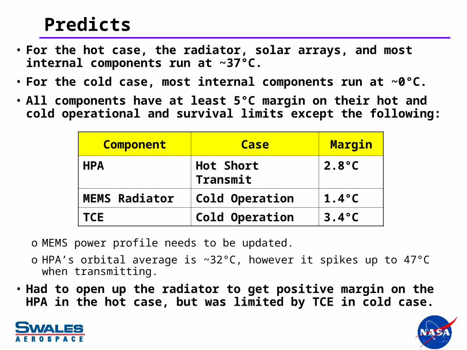
Predicts• For the hot case, the radiator, solar arrays, and most internal
components run at ~37°C.
• For the cold case, most internal components run at ~0°C.
• All components have at least 5°C margin on their hot and cold operational and survival limits except the following:
o MEMS power profile needs to be updated.
o HPA’s orbital average is ~32°C, however it spikes up to 47°C when transmitting.
• Had to open up the radiator to get positive margin on the HPA in the hot case, but was limited by TCE in cold case.
Component Case Margin
HPA Hot Short Transmit 2.8°C
MEMS Radiator Cold Operation 1.4°C
TCE Cold Operation 3.4°C
Small Model Hints
• ST5 much smaller than most SC
o Same laws of thermodynamics
o Blanket effective emittance higher than standard SC
• Using 0.03 to 0.1 instead of standard 0.005 to 0.03 for larger SC.
• Will find out at spacecraft thermal balance test.
o Errors
• A few square inches to a 100 in2 radiator is a much higher % than it is for a 1000 in2
one.
• Low energy balance. Tracking down tenths of Watts instead of Watts. Not as critical as a cryo cooler where one is worried about milliwatts.
• Pay close attention to details. Some components (ex. connectors) may be similar size to that in a large SC. They would represent a larger % of area on a small SC and can’t be neglected.
o Check sensitivity to critical parameters
• Sensitivity to power for ST5 is 0.5°C per Watt.
• You do this with all spacecraft designs anyway but may be critical with the smaller ones.