Embed Size (px)
Citation preview

Design and Analysis of a Novel CompliantMechanism with RPR Degrees of FreedomShuang Zhang
Beijing University of TechnologyJing-Fang Liu ( j�[email protected] )
Beijing University of Technology https://orcid.org/0000-0002-9213-1950Hua-Feng Ding
China University of Geosciences(Wuhan)
Original Article
Keywords: Compliant mechanism, RPR degrees of freedom, Motion/force transfer characteristic,Mechanical model, Optimization
Posted Date: July 6th, 2020
DOI: https://doi.org/10.21203/rs.3.rs-39324/v1
License: This work is licensed under a Creative Commons Attribution 4.0 International License. Read Full License
·1·
Title page
Design and Analysis of a Novel Compliant Mechanism with RPR Degrees of Freedom
Shuang Zhang, born in 1991, is currently a PhD candidate in mechanical engineering from Beijing University of Technology, Beijing,
China. He received his bachelor degree from Beijing University of Technology, China, in 2017. His research interests include compliant
mechanisms, and parallel mechanisms.
E-mail: [email protected]
Jing-Fang Liu, born in 1985, is currently an associate professor at Beijing University of Technology, Beijing, China. She received her
doctor degree in mechanical engineering from Yanshan University, Qinhuangdao, Hebei, China, in 2011.
Hua-Feng Ding, born in 1977, is currently a professor at Beijing University of Technology, Beijing, China. He received the first Ph.D.
degrees in mechanical engineering from Yanshan University, Qinghuangdao, Hebei, in 2007, and the second Ph.D. degree in mechanical
engineering from the University of Duisburg-Essen, Essen, Germany, in 2015.
E-mail: [email protected]
Corresponding author:Jing-Fang Liu E-mail:[email protected]

Shuang Zhang et al.
·2·
ORIGINAL ARTICLE
Design and Analysis of a Novel Compliant Mechanism with RPR Degrees of Freedom Shuang Zhang1 • Jing-Fang Liu1, 2 • Hua-Feng Ding1, 3
Abstract: Magnetic drive pump has gotten great achievement A
novel compliant mechanism with RPR degrees of freedom (DOF)
is proposed where R and P represent rotation and translation
DOFs, respectively. The proposed compliant mechanism is
obtained from dimension synthesizing a 2-RPU-UPR rigid
parallel mechanism with the method of optimization of
motion/force transfer characteristic, where R, P and U represent
rotation, translation and universal pairs, respectively. Firstly,
inverse kinematics and Jacobian matrix are analyzed for the
dimensional synthesis. Then, output transmission indexes of
branches in the parallel mechanism are given. Dimensional
synthesis is completed based on the normalized design parameter.
And optimization of flexure joints based on constrained energy is
carried out. Afterwards, the novel compliant mechanism is
obtained by direct replacing method. Mechanical model of the
compliant mechanism including static stiffness and input stiffness
is built based on the pseudo-rigid body model method and virtual
work principle for its future application. Finally, FEA simulation
by Ansys Workbench is carried out to verify DOF, effectiveness of
the dimension synthesis, and compliant model. Optimization of
motion/force transfer characteristic is first applied for the design
of compliant mechanisms to suppress drift of rotation axis in the
paper.
Keywords: Compliant mechanism; RPR degrees of freedom;
Motion/force transfer characteristic; Mechanical model;
Optimization
1 Introduction
With the excellent characteristics of no backlash, no
nonlinear friction and facilitated manufacture, compliant
parallel mechanisms (CPMs) possess potential ability in Shuang Zhang
1 College of Mechanical Engineering and Applied Electronics
Technology, Beijing University of Technology, Beijing, China
2 Key laboratory of advanced manufacturing technology, Beijing
University of Technology, Beijing, China
3 School of Mechanical Engineering and Electronic Information, China
University of Geosciences (Wuhan), Wuhan, China
micro or nano scales precision operations [1-3].
Micro-positioning CPMs with two rotations and one
translation (2R1T) are widely applied in the state-of-art
precision positioning stages where moving platform’s posture can be changeable, such as micro-component
manufacture and assembly, biological cell manipulation,
optical fibers alignment, scanning probe microscopes, and
so on [4-9].
The design method of compliant mechanism is always a
hot topic in mechanism science. In the past few decades,
some effective design methods have been proposed, such as
FACT method [10-11], screw theory method [12] and
topological optimization method [13-14], et, al. Flexure
hinge-based compliant parallel mechanisms are widely
used due to structural similarity to rigid parallel
mechanisms, which can be considered as mechanisms in
which the rigid joint is replaced by the flexible joint in rigid
parallel mechanisms [15-17].For this reason, direct
replacing method [18], which obtains compliant
mechanisms by replacing rigid hinges with flexible hinges,
is the most popular design method. With the help of
existing design methods, a large number of 2R1T compliant
mechanisms have been designed for various uses up to now.
He [4] presented a novel type compact single mirror laser
scanner based on 3-PRS compliant mechanism which is
actuated by the permanent magnetic suspension. Kim [5]
designed and modeled a precision micro-stage based on the
well-known tripod parallel configuration for active
micro-vibration control. Park and Lee [6] proposed a
piezoelectric-driven tilt mirror for fast laser scanner. Kim
[7] developed a nano-precision 2R1T vertical positioning
stage which can compensate for the deformation caused by
gravity. Lee [8] proposed a 3-DOF out-of-plane
nano-positioning stage using a compact bridge-type
displacement amplifier. Hao [9] also proposed a 2R1T
compliant mechanism based on the constrained-based
design method. Most of the existing researches for design
of 2R1T compliant mechanism concentrate on designing of
one with high natural frequency or with large stroke.

Design and Analysis of a Novel Compliant Mechanism with RPR Degrees of Freedom
·3·
However, there are rarely studies on rotational
characteristics of 2R1T compliant mechanisms especially
parasitic motion. The error caused by parasitic motion
seriously hinders practical applications of the compliant
mechanism. It is necessary to eliminate or suppress the
parasitic motion of 2R1T compliant mechanisms. Li [19]
classifies 2R1T parallel mechanisms into four categories
which are PU、P*U*、UP and RPR according to kinematic
characteristics. PU and UP type 2R1T parallel mechanisms
possess determined axis of movement and rotation due to
constrained chain PU and UP, respectively [20-23]. These
two types of parallel mechanisms are not suitable for
miniaturization because of its complicated structure due to
the additional constraint chains. P*U* type 2R1T parallel
mechanisms have two rotation and one translational
time-varying axis which are difficult to be acquired [24-25].
In contrast, RPR type 2R1T parallel mechanisms have two
vertical continuous rotation axes relative to the fixed
coordinate, which are known. One of them is fixed to the
fixed platform; the other one is close to the moving
platform, and its position and direction changes in motion
[26-27]. At the same time, this type of mechanisms has
relatively simple structure. At present, the existing 2R1T
CPMs fall into P*U* type, of which center point of the
moving platform could translate not only along X direction
but also along X and Y directions. This phenomenon
belongs to parasitic motion. The rotation axis is expected to
be as continuous as possible in the working position for
facilitate control, especially for micro and nano
mechanisms.
In addition, the linear micro-actuation such as
piezoelectric actuator is the most popular actuator in CPMs.
In the linear elastic deformation problem, axis drift of
CPMs with rotation DOF actuated by force mainly lies on
the linear deformation caused by actuated force. And the
essential function of the mechanism is to transfer the input
force and motion to the output to forms desired motion.
Motion/force transfer characteristic reflects the essential
function [28-29]. As to rigid parallel mechanisms,
motion/force transfer characteristic reflects transfer ability
from input motion to output motion which can be used in
singular discrimination. A good motion/force transfer
characteristic reflects most of input energy is transferred to
the output’s desired motion. On the contrary, a bad transfer characteristic reflects that input energy is consumed in the
undesired deformation of linkages. Undesired deformation
of flexure joints is the main source of parasitic motion. For
this reason, optimization based on motion/force transfer
characteristic is applied to minimize axis drift of a RPR
flexure hinge-based compliant mechanism, which is
obtained by direct replacement method of 2RPU-UPR rigid
parallel mechanism in the paper.
The remainder of this paper is organized as follows.
Dimension synthesis of the rigid RPR mechanism is carried
out in Section 2. Subsequently, the RPR compliant
mechanism is obtained by direct replacement and
optimization of flexure joints in Section 3. Mechanical
model of the compliant mechanism is built based on the
pseudo-rigid body model method and virtual work principle
in Section 4. In section 5, validation of DoF, effectiveness
of the dimension synthesis and mechanical model by FEA
simulation is presented. Finally, conclusions are given.
2 DIMENSION SYNTHESIS OF THE RIGID RPR MECHANISM
Figure 1 Sketch of the rigid RPR mechanism
The rigid 2-RPU-UPR mechanism [26], selected as the The
rigid 2-RPU-UPR mechanism [26], selected as the rigid
RPR model, is bilaterally symmetrical in initial pose, and
its moving and fixed platforms are isosceles right triangles
which are parallel to each other, as shown in Fig. 1. A fixed
frame -o xyz and a moving frame ' - ' ' 'o x y z are
established at the centers of the fixed and moving platforms,
respectively. The axes x , x point to 1A
1B , meanwhile the
axes z , 'z are perpendicular to the fixed and moving
platforms, respectively. In RPU branch, one of the axes of
U pair is parallel to that of R pair’s, and the other axis is
collinear with x axis. The UPR branch is obtained by
turning the RPU branch upside down, and its R pair is
parallel to x axis. The DoFs of the mechanism are a
rotation around 2oA , a translation along 'oo and a
rotation around 1 3B B .
Motion/force transmission characteristic of a mechanism
can be divided into two parts: input transmission
performance and output transmission performance. The
input transmission performance represents the efficiency of

Shuang Zhang et al.
·4·
power transmitted from the actuated joints to the limbs,
while the output transmission performance represents the
efficiency of power transmitted from the limbs to the moving platform. The input transmission index of the RPR
mechanism is always one. Because of its good input
transfer characteristics, the rigid mechanism is selected in
the paper. And the output transmission index is
max
Oi Ti
i
Oi Ti
S S
S S
o
o (1)
where OiS and Ti
S denotes the output twist and the
transmission wrench of the ith branch chain, respectively.
maxOi TiS S o is presuming efficiency of power, which is
referred to in [28]. As a matter of experience, the output
transmission index of branch chain 2 2A B is equal to 1
when the branch chain 2 2A B is perpendicular to the
moving platform. So only the case that the sizes of moving
platform and fixed platform are same is considered in the
paper, as thus the output transmission index of branch chain
2 2A B is optimal. The main parameters are shown in Fig. 2,
where r1 represents distance from the origin of moving
coordinate system to the moving pair B2, r2 represents
distance from the origin of fixed coordinate system to the
moving pair A1, and P represents distance between the
origins of two coordinate systems. In the following, inverse
kinematic and Jacobian matrix of the 2-RPU-UPR rigid
mechanism are analyzed preparing for the dimensional
synthesis.
Figure 2 Schematic of main parameters
2.1 Inverse kinematics analysis
Pose of the moving platform can be depicted as
0
c s s s c
c s
s c s c c
R (2)
where and are the rotation angles of the moving
platform around the y axis and 'x axis, respectively.
Suppose that the length of 'oo is P , the coordinate of 'o
in the fixed frame is T0Ps Pc . The coordinates of
iB ( 1,2,3i ) in the moving frame are
T
1
T
2
T
1
0 0
0 0
0 0
r
r
r
1
2
3
B
B
B
(3)
And the coordinates of iB in the fixed frame can be
depicted as
i i
B RB oo (4)
The coordinates of Ai in the fixed frame can be depicted
as
T
1 1
T
2 2
T
3 1
( 0 0)
(0 0)
( 0 0)
r
r
r
A
A
A
(5)
According to the relationship
i i ilA B (6)
The inverse kinematics solution of the mechanism can be
obtained
2.2 Analysis of Jacobian matrix
In this section, Jacobian matrix of the rigid RPR
mechanism is analyzed based on screw theory. Four
subspaces of the 2-RPU-UPR parallel mechanism are
obtained by using the method in [30], and are listed in
appendix A.
The velocity of moving platform can be expressed as
1,2,3t i i
i S V J θ& (7)

Design and Analysis of a Novel Compliant Mechanism with RPR Degrees of Freedom
·5·
where
0 0
1 0 0
0 0
0
0 0 0
0
t
c
s
ps s
pc c
S (8)
p
V (9)
, ,=
i a i c i J J J (10)
, , ,1 , ,2=
c i tc i tc i J S S (11)
, , ,1 , ,4=
a i ta i ta i LJ S S (12)
TT T
2 1=
i a,i θ θ 0& & (13)
T
, ,1 , ,2 , ,2 , ,2=
a,i a i a i a i a i θ& & & & & (14)
tS is motion screw system of the moving platform. V
is magnitude of the velocity. iJ is the ith branch’s
Jacobian matrix, a,iθ& is the magnitudes of velocities of
joints in the branch.
Equation (15) can be obtained
1
i t i
&J S V θ (15)
The following equation is obtained by taking reciprocal
product on both sides of Eq. (15) with corresponding
actuated wrench
a b aq &J V J (16)
where
T
1 2 3=
a a a a & & & &, , ,q q q q (17)
T
,1,2
T
,2,3
T
,3,2 3 3
wa t
a wa t
wa t
S S
J S S
S S
(18)
T
,1,2 ,1,2
T
,2,3 ,2,3
T
,3,2 ,3,2 3 3
wa ta
b wa ta
wa ta
S S
J S S
S S
(19)
3 3 3 3
3 3 3 3
=
0 E
E 0 (20)
Furthermore, the following equations can be obtained
a &JV q (21)
a &V Gq (22)
where
1=b a
J J J (23)
1G J (24)
Substitute Eq. (22) into Eq. (17)
,i a i a& &θ G q (25)
where
1
,a i i t
G J S G (23)
By combining the Eq. (25) of each branch and removing
the row vectors corresponding to wrench subspace of
actuation and twist subspace of restrictions, the relationship
between the velocities of actuators and other kinematics
joint is obtained
=a p a
& &θ G q (26)
2.3 Optimization of motion/force transfer performance
It is also found that the motion/force transfer performance

Shuang Zhang et al.
·6·
of parallel mechanisms in the initial symmetrical pose is
better than that in other pose. And motion range of
compliant mechanisms is microscopic. Therefore, the
motion/force transfer performance in the initial position is
used to evaluate the performance of the RPR mechanism in
the paper.
2.3.1 Motion/Force Transmission Analysis
Due to the symmetrical topological structure in initial
position, branch chain 1 1A B and 3 3
A B possess the same
output transmission index. Furthermore, the output
transmission index of branch chain 2 2A B is equal to one.
Stated thus, only output transmission index of branch chain
1 1A B or 3 3
A B needs to be considered. In the paper, the
output transmission index of branch chain 1 1A B is taken
into consideration. For convenience, the screw is
represented by the row vector in this section.
In initial position, after locking driven joints of the
branch chains 2 2A B and 3 3
A B , their twist systems are
T
3
T
T
0 1 0 (0 1 0)
0 1 0 0 1 0
1 0 0 1 0 0
3
3
oA
oB
oB
(27)
T
T
T
0 1 0 (0 1 0)
1 0 0 1 0 0
1 0 0 1 0 0
2
2
2
oA
oA
oB
(28)
And the constrained wrench system can be obtained by
taking reciprocal product on the above twist systems
T
T
T
T
0 0 0 0 0 1
0 1 0 0 1 0
0 0 1 0 0 1
1 0 0 1 0 0
0 0 1 0 0 1
1
2 3
3 3
4 2
5 2
H
H oB
H oB
H oA
H oA
(29)
The output twist is obtained by solving Eq. (30)
=
0
1
o
o
O
O i
S s s
S H
s
(30)
The unit transmission wrench of branch chain 1 1A B is
T
1= 0 0 1 0 0 1
TS oA (31)
And the output transmission index can be solved by
max
=
o
o
T O
T O
S S
S S (32)
The presuming efficiency of power max
oT O
S S of the
RPR mechanism is equal to the distance from 1B to O
S
[28].
(a)
(b)
Figure 3 The parameter design space (a) spatial parameter
design space (b) plan parameter design space
2.3.2 Optimization of Design Parameters
In the paper, the RPR mechanism has three design
parameters 1r , 2
r and P . And they are normalized as
1 2
3
r r PD
(33)
11
rl
D , 2
2
rl
D , 3
Pl
D (34)

Design and Analysis of a Novel Compliant Mechanism with RPR Degrees of Freedom
·7·
where D is a normalized factor. 1l , 2
l and 3l are
non-dimensional and normalized parameters.
Considering the actual application, branch lengths and
the radius of the platform are not desirable too long or too
short. In the paper, the radius of the platform is constrained
between one-half to twice the length of the branch.
Therefor, the three normalized parameters should satisfy
1 2 3
1 2 3
1 2 1
0 , , 3
3
12
2
l l l
l l l
l l l
(35)
The parameter design space can be depicted as shown in
Fig. 3. The shaded area shown in Fig. 3(a) is the set of all
possible points. For convenience, the reasonable parameter
area can be transformed into a triangle plane, as shown in
Fig. 3(b). The relationship between the parameters in
spatial space and those in plan space can be depicted as
2
3 1
3
s l
l lt
(36)
By taking Eqs. (33) - (36) into Eq. (32), the distribution
of the output transmission index can be obtained, as shown
in Fig. 4.
Figure 4 Distribution of output transmission index
The optimal regions can be found from Fig. 4 and it is
redly marked. The point
1.5
0
s
t
(37)
is selected out and expresses the non-dimensional and
normalized parameters are
1
2
3
0.75
1.5
0.75
l
l
l
(38)
According to the actual situation and ensure a compact
structure consideration, design parameters of
1
2
40
80
40
r mm
r mm
P mm
(39)
are determined temporarily.
3 Design of the compliant RPR mechanism
Figure 5 U compliant joint and R compliant joint
Direct replacing method is used for compliant mechanism
in the paper. The key for rapidity and effectiveness of the
method is to replace rigid kinematic pairs in the rigid RPR

Shuang Zhang et al.
·8·
counterpart with suitable flexible joints. Two kinds of
commonly used U compliant joints and R compliant joints
are used to replace corresponding rigid kinematics pairs, as
shown in Fig. 5.
3.1 Optimization of flexible joints
It is assumed that linkages connecting flexure joints of the
RPR compliant mechanism are ideal rigid bodies, and all
deformation occurs on flexible joints. The branch chain of
the compliant parallel mechanism can be regarded as a
cantilever beam with one end fixed, the other end subjected
to loads applied by moving platform and actuated force.
According to statics theory of the rigid parallel mechanism,
the load applied by moving platform can be divided into
three parts including constrained wrench, actuated force
and another force which makes the major deformation of
flexible joints. Undesired motions are constrained by
constrained wrenches of the branch. The smaller the
deformation of a branch coursed by constrained wrenched
is, the better its restraint ability is. Therefore, the
optimization of flexible hinge is carried out by taking the
sum of twice the energy caused by unit constrained
wrenches as the objective function. The objective function
of the jth compliant joint can be defined as
Minimize f cT c
jS C S (40)
where jC is the compliant matrix of the jth compliant
joint, and cS denotes a constrained wrench or an actuated
wrench. Using energy as an optimization index can
overcome the inconsistency of the dimensionality of
translational and rotational compliances.
Flexibility models of the U compliant joint and the R
compliant joint are given in [31] and [32]. For convenience,
in order to remove the coupling between the force and the
moment, the origins of the fixed coordinate systems of the compliant matrices in Fig. 5 are moved to the structural
centers of the compliant joints. The matrices of the U
compliant joint and the R compliant joint can be expressed
as
t x
ty
tz
U
mx
my
mz
cu
cu
cu
cu
cu
cu
C (41)
t x
ty
tz
R
mx
my
mz
cr
cr
cr
cr
cr
cr
C (42)
After removing the actuated joint, the branch chains
RPU and UPR possess the same structure and constraint
wrenches. Therefore, it is only needed to optimize the
flexible hinge of any branch in the RPR compliant
mechanism.
As to the R joint, the objective function in Eq. (40) can
be depicted as
22 2 2 2
1 1tx ty mx mzminimize f cr cr cr cr A B (43)
As to the U joint, the objective function in Eq. (40) can
be depicted as
2 2 2
tx ty mzminimize f cu cu cu (44)
Other criteria are used as constraints. The movement
range of the end platform of the compliant mechanism is
tiny. Normally, when the rotation range of the flexible
hinge is relatively large, design demand of the stroke of the
compliant mechanism is fulfilled. Herein, the rotation angle
should be more than 2 degrees and the constraint on the
rotation angle can be expressed as
,maxanis Y des
r
Et SF
(45)
where SF is the safety factor, and Y
is the yield
strength.
Manufacturability and volume of the compliant joint are
also two important factors. In order to avoid difficulty
machining or over size of the compliant joint, the volume is
constrained to within 12 12 12mm mm mm , and the
thinnest part is not less than 0.3mm . GlobalSearch
Function in MATLAB optimization toolbox is used to
perform the optimization design. And optimization results
are listed in Table. 1.
Table 1 Optimization results of the flexure joints
R Pair 4r mm 12h mm 12b mm 0.4t mm
U Pair 1r mm 12h mm 0.4t mm

Design and Analysis of a Novel Compliant Mechanism with RPR Degrees of Freedom
·9·
3.2 Actuated joint and Motion Amplification
Mechanism
The traditional bridge-type amplification mechanism is
used as P pair in the paper. According to the overall
parameters of the RPR compliant mechanism obtained by
dimension synthesis, the structure of the motion
amplification mechanism is designed to be as compact as
possible, and the amplification ratio is about 10. Draw
lessons from the design method of the traditional
bridge-type amplification mechanism in [33-34], and
structure of the motion amplifier used in the paper is shown
in Fig. 6.
The motion amplifier in each branch chain is placed as
closed as to the base in order to relatively low inertia in
motion. The structure of the whole RPR compliant
mechanism is decided as to now. And sketch of the whole
RPR compliant mechanism is shown in Fig. 7
Figure 6 Sketch of the motion amplifier
Figure 7 The obtained RPR compliant mechanism
4 Mechanical model of the RPR compliant mechanism
The pseudo-rigid body model method and virtual work
principle are used to establish statics model of the RPR
compliant mechanism. Firstly, the motion amplifier is
analyzed. The main part of the motion amplifier is the
flexible leaf joint. And the leaf joint can be regarded as a
pseudo rigid body model composed of a rotating pair and a
translating pair perpendicular to the flexible leaf, as shown
in Fig. 8.
Figure 8 A flexible leaf joint and its simplified model.
In consideration of the force and moment balance at the
equilibrium state, the following equation can be obtained
2 12
x y rf l f l m (46)
From the geometric relationship of one quarter of the
motion amplifier, we can obtain
2
1 12
x
y
d l
d l t
(47)
r r
y t
m c
t f c
(48)
Substitute Eq. (47) and Eq. (48) into Eq. (46), and take
the equations of the three branch chains into matrix
expressions
11 12
21 22
in in out
out in out
D A F A F
D A F A F (49)
where
2 2 2
2 2 211
( , , )4 4 4
r r rl c l c l c
diagA (50)
1 2 1 2 1 212
( , , )4 4 4
r r rl l c l l c l l c
diagA (51)
1 2 1 2 1 221
( , , )4 4 4
r r rl l c l l c l l c
diagA (52)

Shuang Zhang et al.
·10·
2 2 2
1 1 1
22
+4 +4 +4( , , )
4 4 4
r t r t r tl c c l c c l c c
diagA (53)
T
1 2 3=
in in in inf f f F (54)
T
1 2 3in in in ind d d D (55)
T
1 2 3=
out out out outf f f F (56)
T
1 2 3out out out outd d d D (57)
Secondly, a pseudo-rigid body model is built where
motion amplifiers are replaced by three virtual actuated
joints with output forces
T
1 2 3=
out out out outf f f F (58)
and output displacement
T
1 2 3out out out outd d d D (59)
Apply the virtual work principle to the whole
mechanism,
T T
out out J J JF D D K D (60)
where
1 2 9J LD (61)
1
2
9
=
j
j
J
j
k
k
k
KO
(62)
JK is the stiffness matrix, of which diagonal elements are
composed the stiffness of major degree of freedom of the
passive joint in each branch.
Substitute Eq. (26) into Eq. (60), the relationship
between outF and out
D can be obtained
out outF K D (63)
where
T
P J P K G K G (64)
From Eq. (22), Eq. (49), and Eq. (63), we can obtain
inD CF (65)
in in inD C F (66)
where
1
22 21=
C G E A K A (67)
1
11 12 22 21( )
in
C A A K E A K A (68)
C is the compliant matrix of the whole mechanism. inC
is input compliant matrix of the whole mechanism.
5 Model validation with FEA
The DoF, effectiveness of the dimension synthesis,
compliant model of the RPR compliant mechanism are
verified by FEA with ANSYS Workbench. A 3D virtual
model is built which material is assigned as Al-7075 alloy.
5.1 Validation of DoF and effectiveness of the dimension
synthesis
Figure. 9 The RPR compliant mechanism for FEA simulation
In the section, motion amplifiers are replaced by three rigid
translational joint, as shown in Fig. 9, in order to avoid
undesired deformation of motion amplifiers. When 10 m
is applied to the rigid translational joints, successively,
twists of moving platform obtained by theoretical
calculation and simulation are listed in Eq. (69) and Eq.
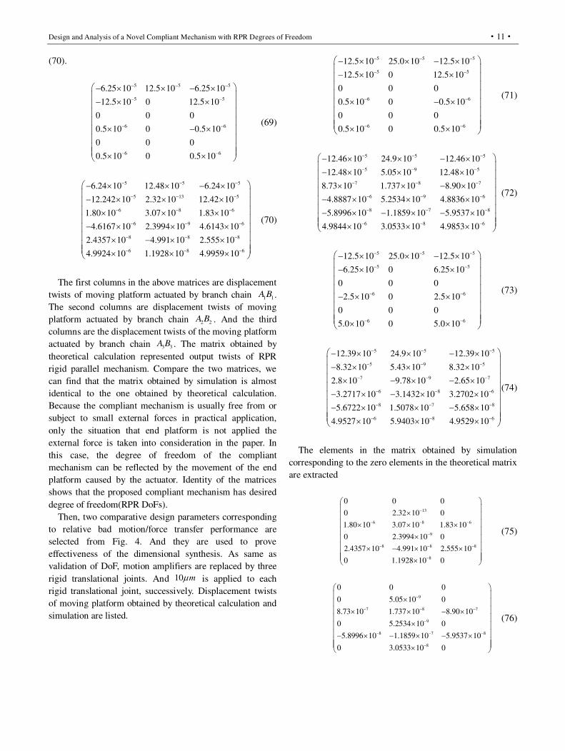
Design and Analysis of a Novel Compliant Mechanism with RPR Degrees of Freedom
·11·
(70).
5 5 5
5 5
6 6
6 6
6.25 10 12.5 10 6.25 10
12.5 10 0 12.5 10
0 0 0
0.5 10 0 0.5 10
0 0 0
0.5 10 0 0.5 10
(69)
5 5 5
5 13 5
6 8 6
6 9 6
8 8 8
6 8 6
6.24 10 12.48 10 6.24 10
12.242 10 2.32 10 12.42 10
1.80 10 3.07 10 1.83 10
4.6167 10 2.3994 10 4.6143 10
2.4357 10 4.991 10 2.555 10
4.9924 10 1.1928 10 4.9959 10
(70)
The first columns in the above matrices are displacement
twists of moving platform actuated by branch chain 1 1A B .
The second columns are displacement twists of moving
platform actuated by branch chain 2 2A B . And the third
columns are the displacement twists of the moving platform
actuated by branch chain 3 3A B . The matrix obtained by
theoretical calculation represented output twists of RPR
rigid parallel mechanism. Compare the two matrices, we
can find that the matrix obtained by simulation is almost
identical to the one obtained by theoretical calculation.
Because the compliant mechanism is usually free from or
subject to small external forces in practical application,
only the situation that end platform is not applied the
external force is taken into consideration in the paper. In
this case, the degree of freedom of the compliant
mechanism can be reflected by the movement of the end
platform caused by the actuator. Identity of the matrices
shows that the proposed compliant mechanism has desired
degree of freedom(RPR DoFs).
Then, two comparative design parameters corresponding
to relative bad motion/force transfer performance are
selected from Fig. 4. And they are used to prove
effectiveness of the dimensional synthesis. As same as
validation of DoF, motion amplifiers are replaced by three
rigid translational joints. And 10 m is applied to each
rigid translational joint, successively. Displacement twists
of moving platform obtained by theoretical calculation and
simulation are listed.
5 5 5
5 5
6 6
6 6
12.5 10 25.0 10 12.5 10
12.5 10 0 12.5 10
0 0 0
0.5 10 0 0.5 10
0 0 0
0.5 10 0 0.5 10
(71)
5 5 5
5 9 5
7 8 7
6 9 6
8 7 8
6 8 6
12.46 10 24.9 10 12.46 10
12.48 10 5.05 10 12.48 10
8.73 10 1.737 10 8.90 10
4.8887 10 5.2534 10 4.8836 10
5.8996 10 1.1859 10 5.9537 10
4.9844 10 3.0533 10 4.9853 10
(72)
5 5 5
5 5
6 6
6 6
12.5 10 25.0 10 12.5 10
6.25 10 0 6.25 10
0 0 0
2.5 10 0 2.5 10
0 0 0
5.0 10 0 5.0 10
(73)
5 5 5
5 9 5
7 9 7
6 8 6
8 7 8
6 8 6
12.39 10 24.9 10 12.39 10
8.32 10 5.43 10 8.32 10
2.8 10 9.78 10 2.65 10
3.2717 10 3.1432 10 3.2702 10
5.6722 10 1.5078 10 5.658 10
4.9527 10 5.9403 10 4.9529 10
(74)
The elements in the matrix obtained by simulation
corresponding to the zero elements in the theoretical matrix
are extracted
13
6 8 6
9
8 8 8
8
0 0 0
0 2.32 10 0
1.80 10 3.07 10 1.83 10
0 2.3994 10 0
2.4357 10 4.991 10 2.555 10
0 1.1928 10 0
(75)
9
7 8 7
9
8 7 8
8
0 0 0
0 5.05 10 0
8.73 10 1.737 10 8.90 10
0 5.2534 10 0
5.8996 10 1.1859 10 5.9537 10
0 3.0533 10 0
(76)

Shuang Zhang et al.
·12·
9
7 9 7
8
8 7 8
8
0 0 0
0 5.43 10 0
2.8 10 9.78 10 2.65 10
0 3.1432 10 0
5.6722 10 1.5078 10 5.658 10
0 5.9403 10 0
(77)
Compare the three matrices in Eqs. (75)-(77), we can
find that the linear displacements of the optimized
mechanism are smaller than these of the comparison groups.
But the angular displacement around z-axis of the
optimized mechanism is larger than these of the
comparison groups. The comparisons indicate that the
dimension synthesis is relatively effective but not perfect. It
is insufficiently that only motion/force transfer
performance is taken into consideration. In addition to the
coupling of force and moment, the main causes of error
should include insufficient restraint capacity. The essence
of constraint is to resist the deformation of branch in the
constraint direction. While optimizing the motion/force
transfer performance, the ability of branch constraints
should be also considered. The optimization of constraint
performance will be studied in our future work.
5.2 Validation of the mechanical model
A unit force is applied to the two input ends of the three
motion amplifiers, successively, the stage deformations
along the three working directions are obtained by the FEA
simulation. Due to the linear deformation, the elements of
compliant matrix of the RPR mechanism are equal to the
values of the stage displacements along the three working
directions. And the stage displacements are given in Eq.
(78).
5 9 5
6 5 6
7 8 7
1.613 10 7.71 10 1.635 10
8.11 10 1.162 10 8.24 10
6.6444 10 1.4613 10 6.7338 10
(78)
5 5
6 5 6
7 21 7
1.8704 10 0 1.8704 10
9.1276 10 1.3255 10 9.1276 10
7.4223 10 -1.0616 10 7.4223 10
(79)
The compliant matrix of the RPR mechanism obtained
by theoretical calculation is listed in Eq. (79). Comparing
Eq. (78) with Eq. (79), the errors between the
corresponding elements constitute the following matrix
16.0% 0 14.4%
12.5% 14% 10.8%
11.7% 10.9% 10.2%
(80)
From Eq. (79), the compliance model obtained by
theoretical calculation is relatively close to the one obtained
by the FEA model with most of the errors lower than 16%,
which illustrates the theoretical calculation is correct.
Similarly to the above process, a unit force is applied to the
two input ends of the three motion amplifiers, successively, and deformations of corresponding motion amplifiers are obtained by the FEA simulation. The obtained values of the
deformations are equal to elements of the input stiffness
matrix. The input stiffness matrix obtained by FEA
simulation and theoretical calculation are listed in Eq. (81)
and Eq. (82), respectively. In addition, the errors between
the corresponding elements constitute a matrix, as shown in
Eq. (83).
7
7
7
1.5653 10 0 0
0 1.0218 10 0
0 0 1.5073 10
(81)
7
7
7
1.4083 10 0 0
0 1.2084 10 0
0 0 1.4083 10
(82)
10.0% 0 0
0 18.3% 0
0 0 6.6%
(83)
From Eq. (83), we can find that the maximum margin is
18.3% which is relative high, but acceptable. The error is
mainly caused by undesired deformation of the motion
amplifier. The motion amplifier is regarded as planar
mechanism which ignores out-of-plane deformation. But
it’s prone to out-of-plane deformation in application of
spatial mechanisms.
8.4 0 0
0 9.5 0
0 0 8.4
(84)
Finally, amplify ratios are obtained by the FEA
simulation, and are listed in the following matrix. From Eq.
(84), the amplify ratio meets the design requirement which
requires the amplify ratio is equal to about 10.

Design and Analysis of a Novel Compliant Mechanism with RPR Degrees of Freedom
·13·
6 Conclusion
This paper presents the design and analysis of a novel
2R1T compliant mechanism which possesses RPR degree
of freedom by direct replacing method. The moving
platform has two rotation axes relative to the fixed
coordinate, which are always vertical. One of the two axes
is located at the fixed platform; the other is close to the
moving platform, and the position and direction both
change in motion. Draw on the experience of dimension
synthesis method for rigid parallel mechanisms, the
optimization of motion/force transfer characteristics is
applied for the design of the RPR compliant mechanism.
Based on the analysis of kinematic and Jacobian matrix, the
optimization index is obtained. Non-dimensional and
normalized parameters of the mechanism are used for
dimension synthesis. Then, optimization for the compliant
joint is carried and undesired deformations of flexure joints
caused by constrained wrenches are minimized. Afterwards,
mechanical modeling is built for future application based
on the pseudo-rigid body model method and virtual work
principle. The DoF, effectiveness of the dimension
synthesis, compliant model of the RPR compliant
mechanism are verified by FEA simulation. The validation illustrates that the compliant mechanism has RPR degree of
freedom. From comparisons of three design parameter
cases, it is found that partial undesired motion is effectively
suppressed for the optimal design parameter. The
dimension synthesis method used in the paper is applied to
the compliant parallel mechanism with rotation degree of
freedom which is relatively effective. In the future work,
dimension synthesis method for the compliant parallel
mechanism with rotation degree of freedom will be
improved to reduce parasitic motion.
7 Declaration
Funding
Supported by National Natural Science Foundation of
China (Grant No. 51975007)
Availability of data and materials
The datasets supporting the conclusions of this article are
included within the article.
Competing interests
The authors declare no competing financial interests.
Consent for publication
Not applicable
Ethics approval and consent to participate
Not applicable
References [1] B J Yi, G Chung, H Na, et al., Design and experiment of a 3-DOF
parallel micro-mechanism utilizing flexure hinges. IEEE Transaction
on Robotics and Automation 2003;19(4):604-612
[2] C Werner, P Rosielle, M Steinbuch. Design of a long stroke
translation stage for AFM. International Journal of Machine Tools &
Manufacture 2010; 50(2):183-190
[3] K B Choi, D H Kim. Monolithic parallel linear compliant
mechanism for two axes ultra-precision linear motion. The Review
of scientific instruments 2006;77(6): 065106-1-065106-7
[4] N He, W Jia, M Gong, et al. Design and mechanism analysis of a
novel type compact single mirror laser scanner. Sensors and
Actuators A-Physical 2006; 125(2):482-485
[5] H S Kim, Y M Cho. Design and modeling of a novel 3-DOF
precision micro-stage. Mechatronics 2009;19(5):598-608
[6] J H Park1, H S Lee. Design of a piezoelectric-driven tilt mirror for a
fast laser scanner. Japanese journal of applied physics
2012;51(9):1-14
[7] H Kim, J Kim, D Ahn, et al. Development of a nano-precision
3-DOF vertical positioning system with a flexure hinge. IEEE
Transactions on Nanotechnology 2013;12(2):234-245
[8] H J Lee, H C Kim, H Y Kim, et al. Optimal design and experiment
of a three-axis out-of-plane nano positioning stage using a new
compact bridge-type displacement amplifier. The Review of
scientific instruments 2013;84(11):115103
[9] G B Hao, X He. Designing a monolithic tip-tilt-piston flexure
manipulator. Archives of Civil & Mechanical Engineering
2017;17(4):871-879
[10] J B Hopkins, M L Culpepper. Synthesis of multi-degree of freedom
parallel flexure system concepts via Freedom and Constraint
Topology (FACT)—Part I: Principles. Precision Engineering
2010;34(2):259-270
[11] J B Hopkins, M L Culpepper. Synthesis of multi-degree of freedom
parallel flexure system concepts via Freedom and Constraint
Topology (FACT)—Part II: Practice. Precision Engineering
2010;34(2):271-278
[12] J Yu, S Li, H J Su, and Culpepper ML. Screw theory based
methodology for the deterministic type synthesis of flexure
mechanisms. Journal of Mechanisms and Robotics 2011;3(3):031008
[13] G Ananthasuresh, S Kota, Y Gianchandani. A methodical approach
to the design of compliant micro mechanisms. Solid-state sensor and
actuator workshop. Hilton Head Island, SC, 1994, pp. 189-192.
[14] M Jin, X Zhang. A new topology optimization method for planar
compliant parallel mechanisms. Mechanism and Machine Theory
2016;9(5):42-58
[15] Y K Yong, T F Lu. Kinetostatic modeling of 3-RRR compliant
micro-motion stages with flexure hinges. Mechanism and Machine
Theory 2009;44(6):1156-1175
[16] Y Li, Q Xu. A totally decoupled piezo-driven XYZ flexure parallel
micropositioning stage for micro/nanomanipulation. IEEE
Transactions on Automation science and Engineering
2011;8(2):265-279
[17] Y Li, Q Xu. Design and optimization of an XYZ parallel

Shuang Zhang et al.
·14·
micromanipulator with flexure hinges. Journal of Intelligent and
Robotic Systems 2009;55(4): 77-402
[18] Z Gao, D Zhang. Design, analysis and fabrication of a
multidimensional acceleration sensor based on fully decoupled
compliant parallel mechanism. Sensors and Actuators A-Physical
2010;163(1):418-427
[19] Q C Li,X X Chai,Q H Chen. Review on 2R1T 3-DOF parallel
mechanisms. Chinese Science Bulletin 2017;62(14):1507-1519
[20] F Xie, X J Liu, J Wang. A 3-DOF parallel manufacturing module and
its kinematic optimization. Robotics and Computer Integrated
Manufacturing 2012;2(8):334-343
[21] F Xie, X J Liu, Li T. A comparison study on the orientation
capability and parasitic motions of two novel articulated tool heads
with parallel kinematics. Advances in Mechanical Engineering
2013;5:249103
[22] X Kong, C M Gosselin. Type synthesis of three-dof up-equivalent
parallel manipulators using a virtual-chain approach. Advances in
Robot Kinematics, Netherlands: Springer, 2006, p. 123-132.
[23] T Huang, M Li, X Zhao, et al. Conceptual design and dimensional
synthesis for a 3-DOF module of the TriVariant-a novel 5-DOF
reconfigurable hybrid robot. IEEE Transactions on Robotics
2005;2(1):449-456
[24] K H Hunt. Structural kinematics of in-parallel-actuated robot-arms.
Journal of Mechanical Design 1983;105;705-712
[25] T Huang, H Liu. Parallel mechanism having two rotational and one
translational degrees of freedom. Patent 7793564, USA 2010.
[26] Q C Li, Q H Chen, et al. Three degree of freedom parallel
mechanism with two vertical staggered axes. Patent, CN202292114U,
Chinese 2010.
[27] Q C Li, J M Hervé. Type synthesis of 3-DOF RPR-equivalent
parallel mechanisms. IEEE Transaction on Robotics
2014;30:1333-1343
[28] J Wang, C Wu, X J Liu. Performance evaluation of parallel
manipulators: Motion/force transmissibility and its index.
Mechanism and Machine Theory 2010;45(10):1462-1476
[29] X J Liu, J Wang. A new methodology for optimal kinematic design
of parallel mechanisms. Mechanism and Machine Theory
2007;42(9):1210-1224, 2007
[30] T Huang, H T Liu, D G Chetwynd. Generalized Jacobian analysis of
lower mobility manipulators. Mechanism and Machine Theory
2011;46(5):831-844
[31] G Palmieri, M C Palpacelli, M Callegari. Study of a fully compliant
U-joint designed for minirobotics applications. Journal of
Mechanical Design 2012;134(12):1-9
[32] G Chen, X Liu, Y Du. Elliptical-arc-fillet flexure hinges: toward a
generalized model for commonly used flexure hinges. Journal of
Mechanical Design 2011;133(8):081002
[33] P B Liu, P Yan. A new model analysis approach for bridge-type
amplifiers supporting nano-stage design. Mechanism and Machine
Theory 2016;99(5):176–18,
[34] K Qian, Y Xiang, C Fang, et al. Analysis of the displacement
amplification ratio of bridge-type mechanism. Mechanism and
Machine Theory 2015;87(5):45-56.
Biographical notes
Shuang Zhang, born in 1991, is currently a PhD candidate in
mechanical engineering from Beijing University of Technology,
Beijing, China. He received his bachelor degree from Beijing
University of Technology, China, in 2017. His research interests
include compliant mechanisms, and parallel mechanisms.
E-mail: [email protected]
Jing-Fang Liu, born in 1985, is currently an associate professor
at Beijing University of Technology, Beijing, China. She received
her doctor degree in mechanical engineering from Yanshan
University, Qinhuangdao, Hebei, China, in 2011.
Hua-Feng Ding, born in 1977, is currently a professor at Beijing
University of Technology, Beijing, China. He received the first
Ph.D. degrees in mechanical engineering from Yanshan University,
Qinghuangdao, Hebei, in 2007, and the second Ph.D. degree in
mechanical engineering from the University of Duisburg-Essen,
Essen, Germany, in 2015.
E-mail: [email protected]
Appendix
In the following screw groups, the number of the
subscript indicates its corresponding branch. The bases of
the branch permitted twist subspaces:
TT
,1,1 1
TT
,1,2 1 1
TT
,1,3 1
TT
,1,4 1
0 1 0 0 1 0
0 0 0
0 1 0 0 1 0
0 0
ta
ta
ta
tac s c s
S o A
S A B
S o B
S o B
TT
,2,1 2
TT
,2,2 2
TT
,2,3 2 2
TT
,2,4 2
0 1 0 0 1 0
0 0
0 0 0
0 0
ta
ta
ta
ta
c s c s
c s c s
S o A
S o A
S A B
S o B
TT
,3,1 3
TT
,3,2 3 3
TT
,3,3 3
TT
,3,4 3
0 1 0 0 1 0
0 0 0
0 1 0 0 1 0
0 0
ta
ta
ta
tac s c s
S o A
S A B
S o B
S o B
The bases of the branch constrained wrench subspaces:
TTT
,1,1 1 3
TT
,1,2 1
0 0 0 0 1 0
0 1 0 0 1 0
wc
wc
S B B
S o B
T
,2,1
TT
,2,2 2
0 0 0 0
0 0
wc
wc
s c
c s c s
S
S o A

Design and Analysis of a Novel Compliant Mechanism with RPR Degrees of Freedom
·15·
TTT
,3,1 1 3
TT
,3,2 3
0 0 0 0 1 0
0 1 0 0 1 0
wc
wc
S B B
S o B
The bases of the branch actuated wrench subspaces:
TT T T
,1,1 1 1 1 1 1
TT T T
,1,2 1 1 1 1 1
TT
,1,3 1
T
,1,4
0 1 0 0 1 0
0 0
0 0 0 0
wa
wa
wa
wa
c s c s
c s
S A B o B A B
S A B o A A B
S o A
S
T
,2,1
TT
,2,2 2
TT T T
,2,3 2 2 2 2 2
TT
,2,4 2
0 0 0 0 1 0
0 1 0 0 1 0
0 1 0 0 1 0
wa
wa
wa
wa
S
S o B
S A B o A A B
S o A
TT T T
,3,1 3 3 3 3 3
TT T T
,3,2 3 3 3 3 3
TT
,3,3 3
T
,3,4
0 1 0 0 1 0
0 0
0 0 0 0
wa
wa
wa
wa
c s c s
c s
S A B o B A B
S A B o A A B
S o A
S
The bases of the branch constrained twist subspaces:
TT T T
,1,1 1 1 1 1 1
T
,1,20 0 0 0 1 0
tc
tc
S A B o B A B
S
TT T T
,2,1 2 2 2 2 2
T
,2,20 0 0 0
tc
tcc s
S A B o A A B
S
TT T T
,3,1 3 3 3 3 3
T
,3,20 0 0 0 1 0
tc
tc
S A B o B A B
S

Figures
Figure 1
Sketch of the rigid RPR mechanism
Figure 2
Schematic of main parameters

Figure 3
The parameter design space (a) spatial parameter design space (b) plan parameter design space

Figure 4
Distribution of output transmission index
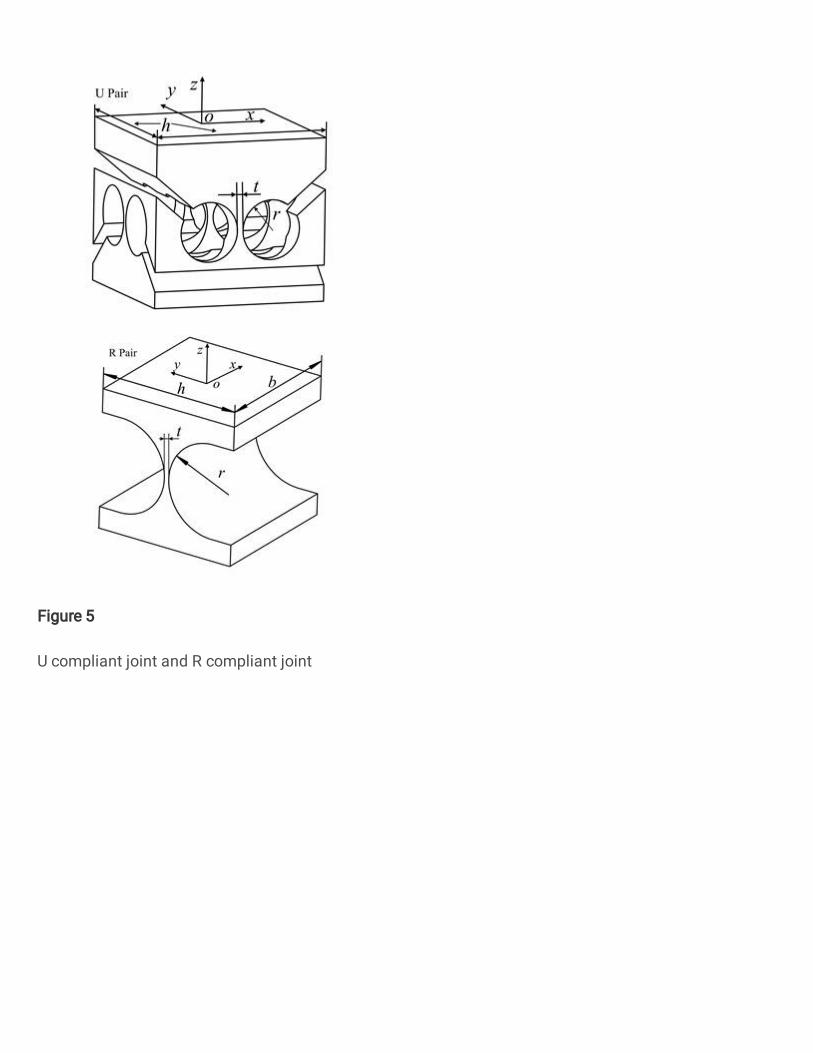
Figure 5
U compliant joint and R compliant joint

Figure 6
Sketch of the motion ampli�er
Figure 7
The obtained RPR compliant mechanism

Figure 8
A �exible leaf joint and its simplified model.
Figure 9
The RPR compliant mechanism for FEA simulation