Embed Size (px)
Citation preview

A Novel Compact Compliant Actuator Design for Rehabilitation Robots
Haoyong Yu1, 2, Sunan Huang1, Nitish V. Thakor1, Gong Chen1, 2, Siew-Lok Toh2
1SiNAPSE: Singapore Institute of Neurotechnology 2Department of Bioengineering
National University of Singapore, Singapore [email protected]
Manolo STA Cruz
HOPE Technik Pte. Ltd, Singapore [email protected]
Yassine Ghorbel
Department of Mechanical Engineering University of Stuttgart
Stuttgart, Germany [email protected]
Chi Zhu
Department of Systems Life Engineering Maebashi Institute of Technology
Maebashi, Gunma, Japan [email protected]
Abstract—Rehabilitation robots have direct physical
interaction with human body. Ideally, actuators for rehabilitation robots should be compliant, force controllable, and back drivable due to safety and control considerations. Various designs of Series Elastic Actuators (SEA) have been developed for these applications. However, current SEA designs face a common performance limitation due to the compromise on the spring stiffness selection. This paper presents a novel compact compliant force control actuator design for portable rehabilitation robots to overcome the performance limitations in current SEAs. Our design consists of a servomotor, a ball screw, a torsional spring between the motor and the ball screw, and a set of translational springs between the ball screw nut and the external load. The soft translational springs are used to handle the low force operation and reduce output impedance, stiction, and external shock load. The torsional spring, being in the high speed range, has high effective stiffness and improves the system bandwidth in large force operation when the translational springs are fully compressed. This design is also more compact due to the smaller size of the springs. We explain the construction and the working principle of our new design, followed by the dynamic modeling and analysis of the actuator. We also show the preliminary testing results of a prototype actuator designed for a lower limb exoskeleton for gait rehabilitation.
Index Terms—Human robot interaction, compliant actuator, variable impedance, rehabilitation robotics
I. INTRODUCTION In recent years, due to the rapidly aging populations in
most developed nations, there is a strong need for service robots, assistive and rehabilitation robots in both domestic [1][2] and hospital settings [3] . In these applications, the robots have to have direct interaction with humans and safety is a critical concern. This has driven the need of research on variable impedance, soft and compliant actuators for safe and human-friendly robotics applications [4]. Safe human-machine interaction requires light-weight actuators with intrinsic compliance and low output impedance. This is especially true
for exoskeleton robots for neurorehabilitation where the control of the assistive force based on the needs of individual patient is important [5]. This requires actuators that can achieve force control, impedance control and back-drivability [6]. Many different compliant actuator designs have been proposed for human friendly robotic applications [7][8]. The most common compliant actuator design adopted is the Series Elastic Actuator (SEA) design developed by J. Pratt and Williamson [9][10]. By introducing an elastic element between the load and the geared motor, the inertia and non-linear frictions of the motor and the transmission are decoupled from the load and external impacts and shocks are isolated from the gear transmission. Therefore, in human friendly robotics applications, SEAs are known to offer a range of advantages over stiff actuators, which include high force/torque controllability and fidelity, low output impedance, back-drivability, tolerance to shock and impacts.
Many different SEAs have been developed for assistive and rehabilitation robots. In [11], J. Pratt et al used the linear SEA to design an assistive knee robot. To achieve more compact and direction integration with the exoskeleton joints, several rotary SEAs were developed [12] [13] [14].
Although current SEAs have achieved reasonable performance, they still face a common fundamental limitation that is the fixed spring constant of the elastic element as discussed by Pratt et al in [10]. The performance of the SEAs largely depends on spring constant. Soft spring produces high fidelity of force control, low output impedance, and reduces stiction, but also limits the force range and the force control bandwidth at high force range. On the other hand, stiff spring increases large force bandwidth, but reduces force fidelity. In order to achieve the desired output force/torque, most current SEAs are designed with very stiff springs, leading to compromised force control performance, low intrinsic compliance and back-drivability, and bulky and heavy systems. The novel design presented in this paper aims to
2013 IEEE International Conference on Rehabilitation Robotics June 24-26, 2013 Seattle, Washington USA
978-1-4673-6024-1/13/$31.00 ©2013 IEEE

overcome the above limitations of the conventional SEAs while improve the performance.
The novel design concept was first proposed in [15] and supported with simulation results. In this paper, we will introduce the prototype design and its force control performance supported with the experimental results. The rest of this paper is organized as follows: Section II presents the design and its working principle; section III presents the dynamic modeling and analysis, followed by basic experimental results of the force control performance of the actuator in section IV; Section V gives a brief introduction to a portable knee ankle robot for stroke rehabilitation based on this actuator design; and section VI provides a summary and the future work.
II. WORKING PRINCIPLE OF THE ACTUATOR DESIGN Fig. 1 illustrates the composition of the novel actuator. It
consists of a servomotor with a rotary encoder, one torsional spring assembly with another rotary encoder, a pair of spur gear with appropriate gear ratio to transmit the motion to the ball screw which converts the rotary motion of the shaft to linear motion of the nut, a set of linear springs attached to the ball screw nut to transmit the force to a carriage which has an force output pin to transmit the force to the load (prospective robot link), and a linear position sensor installed in the carriage to measure the displacement of the linear spring. The two rotary encoders measure the angular deflection of the torsional spring. In this design, the stiffness of the linear spring is chosen to be small so that the actuator can be truly compliant and provide high force control fidelity. The torsion spring is physically small, but it has high effective stiffness as it is located in the high speed range as illustrated in the next section. Due to the difference in spring constant, when the actuator is working in the low force range, the force control is based on the linear spring and the torsional spring behaves like a rigid link. However, when the actuator is working in the high force range, the soft linear is fully compressed and the force control is based on the torsional spring. Therefore, we can achieve a much smaller physical size of the overall actuator compared to existing SEA designs and make it ideal for wearable exoskeleton application.
Ball screw shaft
DC Motor
Torsional spring
Force output pin
Compressive spring
Connection joint
Encoder
Motor encoder
Fig.1. Principle of the actuator design (CAD model)
Fig.2. A prototype of the novel compliant actuator Fig.2 shows actuator prototype built based on this design for an exoskeleton system for lower limb rehabilitation for stroke patients as briefly described in section V. The actuator is designed to be able to provide up to 60Nm assistive torque at the lower limb joints. A Maxon DC brushless motor (EC 4-pole 120 Watt 36V) is used for the design due to its lightweight (0.175kg) and low moment of inertia. The ball screw selected from Eichenberger Gewinde AG has a pitch of 2mm/rev and can output over 1000N force. The linear springs have spring constant of 24 N/mm and a working stroke of 10 mm. They can provide an output force of 240 N before fully compressed. They are used to operate in the range of about 25% of the full force. The torsional spring has a spring constant of 0.606 Nm/rad and a deflection range of 72 degrees. The incremental rotary encoder has a resolution of 1024 lines/rev. The total mass of the actuator is 0.84kg.
The force resolution at low force depends on the stiffness of the linear spring, the position sensor, and the A/D convertor in the data acquisition system. For a 12 bit A/D convertor and a linear potentiometer of 25 mm, the force resolution is given as δF= 2N/mm*25mm/212=0.146N. This is a very fine resolution for human machine interaction at low force range. The force resolution at high force range depends on the spring constant of the torsional spring, the resolution of the rotary encoders, and the pitch of the ball screw. At the rotational torque level, this can be given as δτ=0.606 (2π/1024)=0.003716Nm. Converting to linear output force, this will be δF=0.003716(2π/0.002)=11.68Ν. This can be further improved if a quadrature reading of the encoder is implemented and a softer torsional spring is used.
III. DYNAMIC MODELING AND ANALYSIS In order to analyze the actuator performance at the output
end, which produces linear output force, the actuator is modeled as a system consists of translational elements by converting the rotary elements to equivalent translational elements. The actuator model for the equivalent translational motion is shown in Fig.3 (a). In this model, F1 is motor input force, m1 is equivalent mass of the motor plus the torsional spring coupler and the encoder as derived in (1) where J1 refers to moment of inertia of the motor and the torsional spring coupler and the encoder, p is the pitch of the ball screw, m2 is equivalent mass of the ball screw and the gears as
derived in (2) where J2 refers to moment of inertia for the ball screw and the gears, k1 is considered as the equivalent translational spring constant of the torsional spring kt as derived in (3), k2 is spring constant of the translational spring, b1 and b2 are the viscous damping for motor and ball screw respectively, and Fo is output force.
m1= J1 (2π/p)2 (1) m2= J2 (2π/p)2 (2)
k1= kt (2π/p)2 (3)
(a)
(b)
(c)
Fig.3. Modeling of the series elastic actuator in translational motion. (a) The general case. (b) Model for low force range. (c) Model for high force range.
TABLE 1: PARAMETERS OF THE ACTUATOR PROTOTYPE
Values of the hardware parameters for rotational motion
Values of the hardware parameters for equivalent
translational motion J1=5.517 x10⁻⁶ kg.m2 m1= J1 (2π/p)2 =54.4 Kg J2 =7.406 x 10⁻⁶ kg.m2 m2= J2 (2π/p)2 =73 Kg Torsional spring kt =0.606 Nm/rad k1= kt (2π/p)2 =5.98 x 10⁶ N/m Linear spring k2 = 24x103 N/m k2= 24x103 N/m Pitch of the ball screw (p) =2 x 10⁻³ m p=2 x 10⁻³ m Rotary encoder resolution=1024 /rev Force resolution 11.68N Linear potentiometer 25 mm Force resolution 0.146N Total weight of actuator 0.84Kg
The physical parameters of the actuator prototype are listed in table 1, where both the original number and the equivalent translational values are given for the dynamic modeling and analysis purpose. We can see that the spring constant k1 derived from the torsion spring is 250 times that of k2, meaning the torsional spring can be considered to be a rigid link when the output force is low and the actuator behaves like a normal SEA with the linear spring only. The model of the actuator can be simplified as shown in Fig.3 (b). When the
output force reaches a level when the linear spring is fully compressed, the actuator will behave like a SEA with only the torsional spring as shown the model in Fig.3 (c). Because of the simplified model, we can design the actuator controllers following the same methods for the normal SEAs as proposed in [10].
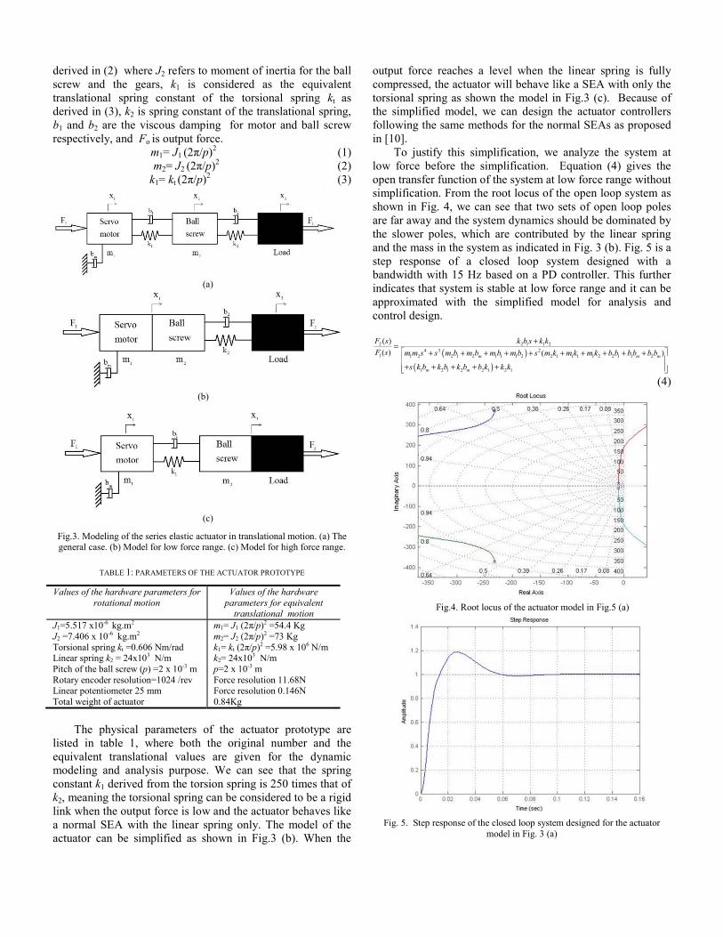
To justify this simplification, we analyze the system at low force before the simplification. Equation (4) gives the open transfer function of the system at low force range without simplification. From the root locus of the open loop system as shown in Fig. 4, we can see that two sets of open loop poles are far away and the system dynamics should be dominated by the slower poles, which are contributed by the linear spring and the mass in the system as indicated in Fig. 3 (b). Fig. 5 is a step response of a closed loop system designed with a bandwidth with 15 Hz based on a PD controller. This further indicates that system is stable at low force range and it can be approximated with the simplified model for analysis and control design.
( )( )
2 2 1 1 24 3 2
1 1 2 2 1 2 1 1 1 2 2 1 1 1 1 2 2 1 1 2
1 2 1 2 2 1 2 1
( )( ) ( )m m m
m m
F s k b s k kF s m m s s m b m b m b m b s m k m k m k b b b b b b
s k b k b k b b k k k
+=⎡ ⎤+ + + + + + + + + +⎢ ⎥+ + + + +⎢ ⎥⎣ ⎦
(4)
Fig.4. Root locus of the actuator model in Fig.5 (a)
Fig. 5. Step response of the closed loop system designed for the actuator
model in Fig. 3 (a)

Therefore, this actuator has different impedance at different force ranges. The actuator control system needs to switch between the controllers with different control designs for the two force ranges. Fig. 6 shows the controller structure used for the system. With this design, the actuator can be truly compliant and back-drivable at low force range. At low force, a controller can be designed to achieve a relatively high closed bandwidth without saturating the motor and amplifier, yet achieve high force fidelity. A 15 Hz bandwidth is achieved for our prototype actuator, which is more than sufficient for gait rehabilitation application. In high force range, very low gain controller can be used to achieve the required bandwidth.
Fig. 6. Control system of the actuator
IV. EXPERIMENTAL RESULTS ON FORCE CONTROL In this section, we will show the force tracking
performance of the actuator with the output pins locked. The experimental system consists of the actuator mounted on the testing jig, a real-time controller, a motor driver, and a host PC. The motor driver is Elmo Harmonica 5/60 which can provide a maximum power output 200W and a continuous output current of 5A. The controller is the National Instruments (NI) CompactRIO 9074 embedded control and data acquisition system. We use NI 9215 (Analog Input module), NI 9263 (Analog Output module), and NI 9516 (Encoder module) for the data acquisition. The entire control system has two modules: monitoring (signal generator and program monitoring) and FPGA (control algorithm). The sampling period for our test is 50μsec.
Low force control. According to our design, the low force is generated by the linear spring and its range is from 0 to 240N. Fig. 7 shows the force tracking performance of sinusoidal signal at 2 Hz. The tracking error is less than 1 %, indicating very high force fidelity.
(a) Force output signal versus input signal
(b) Force output error
Fig. 7. Low force tracking performance at 2 Hz.
Fig. 8 shows the tracking performance of a 15 Hz sinusoidal signal. It can be seen that the output tracks input without obvious phase lag and the error is around 10%. This indicates that the closed loop system can achieve at least a 15 Hz bandwidth. It should be noted that at low force control, the both the torsional spring and the linear spring are there and the actuator performs perfectly without any oscillation. This proves that the two-spring system will achieve stable control without oscillation.
(a) Force output signal versus input signal
(b) Force output error
Fig. 8. Low force tracking performance at 15 Hz.
Ramp input control. In a practical application, the desired force profile can vary between the low force and high force range. The controller has to be able to sense the correct force

level and switch to the other controller without any stability issue. We use a ramp input signal from 0 to 280 N for this test.
Fig. 9. Force Control Performance with Ramp Input
Fig.9 shows the ramp input control results. It can be seen that the controller senses and switches at the crossover point without causing any problems. It can also be noted that a low force range the signal is very smooth, but at high force range, the measured signal zigzags. This is because the force resolution at high force range is 11.68N with the current encoder and torsional spring stiffness used in the design. We will implement quadrature encoder reading and using a softer torsional spring in the next stage of testing and the force resolution will be increased by several times.
High force control. The high force control is based on the
measurement of the deflection of the torsional spring. In order to test the force tracking performance at high force range, we first increase the force level above 300N and superimpose a sinusoidal component to it.
Fig. 11 shows the force tracking of a 15 Hz signal. We can see that the output tracks the input well. However, due to coarse force resolution, the output signal has an error of about 15N, which is about 5% of the amplitude. This performance is acceptable considering the high force and high frequency. We believe the performance can be further improved once force resolution at high force range is improved.
(a) Force output signal versus input signal
(b) Force output error
Fig. 11. High force tracking performance at 15 Hz
V. APPLICATION TO A PORTABLE REHABILITATION ROBOT Lower limb robotic device for gait rehabilitation has
attracted strong interest in the research community in recent years [11][16][17][18][19]. However, due to inefficient actuator design, most of are quite bulky and can’t be really portable. The ankle-foot orthosis to assist drop foot developed by Blaya and Herr at MIT [16] weighs 6.8lbs for just the ankle joint. The knee assistive device developed by Tibion [18] also weighs more than 4.5kg for just the knee joint. The lightweight knee-ankle-foot orthosis (KAFO) was recently developed at University of Michigan [20]. However, due to the design with pneumatic actuators, it needs to be tethered to a stationary compressor and it can’t be portable.
We are developing a home-based wearable knee ankle robot for gait rehabilitation based on the novel actuator design presented in this paper. Fig. 12 shows the concept design of the robot. The modular system consists of an ankle foot module and a knee module. Each module is driven with the same compact compliant force controllable actuator. The structure of the system is made of light weight carbon fiber composite material. The overall weight for the mechanical module is less than 4Kg. Fig. 13 shows the prototype of the robot under development.
Knee Module Release
Knee module actuator
Foot plate and pressure sensor
Ankle joint sensor
Knee joint sensor
Ankle module actuator
Ankle module Attachment
Knee module attachment
IMU sensor
IMU sensor
EMG sensors
EMG sensors
Fig.12. Concept design of the knee ankle robot

Fig.2. Prototype of the knee ankle robot
VI. CONCLUSION AND FUTURE WORK This paper presented a novel compact compliant design that
overcomes the fundamental limitations of current series elastic actuator designs. By introducing one extra torsional spring at the high speed range to handle the high force operation, a truly compliant actuator with excellent force control fidelity and high bandwidth is achieved. The preliminary experimental results from the prototype actuator validated the design concept and demonstrated excellent force tracking performance at both low and high force range. We also presented how this actuator has been implemented in a wearable exoskeleton for gait rehabilitation. In the next stage of our research, we will continue to characterize the performance of the actuator and test the actuator with various control designs for the control of the exoskeleton.
ACKNOWLEDGMENT This research is funded by the FRC Start-up Grant (R -397-
000-114-133) provided by the Faculty of Engineering, National University of Singapore.
REFERENCES [1] Yu, H., Spenko, M., and Dubowsky, S. "An Adaptive Shared Control
System for an Intelligent Mobility Aid for the Elderly." Autonomous Robots, Vol. 15, pp. 53-66, 2003.
[2] Chi Zhu, Masashi Oda, Haoyong Yu, Hideomi Watanabe and Yuling Yan (2011). Walking Support and Power Assistance of a Wheelchair Typed Omnidirectional Mobile Robot with Admittance Control, Mobile
Robots - Current Trends, Zoran Gacovski (Ed.), ISBN: 978-953-307-716-1, InTech.
[3] S. Jezernik,G. Colombo,T. Keller, F. Morari, “Robotic orthosis lokomat: a rehabilitation and research tool,” Neuromodulation, Vol.6, No. 2, pp. 108-115, 2003.
[4] A. Albu-Schaffer, O. Eiberger, M. Grebenstein, S. Haddadin, C. Ott, T. Wimbock, S. Wolf, G. Hirzinger, “Soft robotics,” IEEE Robotics & Automation Magazine, Vol.15, No.3, pp.20-30, September 2008.
[5] H. Vallery,J. Veneman, E. Asseldonk, R. Ekkelenkamp, M. Buss, H. Kooij, “Compliant actuation of rehabilitation robots,” IEEE Robotics & Automation Magazine, Vol.15, No.3, pp.60-69, September 2008.
[6] C. Yang, G. Ganesh, S. Haddadin, S. Parusel, A. Albu-Schaeffer, E. Burdet, “Human-like adaptation of force and impedance in stable and unstable interactions,” IEEE Trans. on Robotics, July 2011.
[7] R. V. Ham, T. Sugar, B. Vanderborght, K. Hollander, and D. Lefeber,“Compliant actuator designs,” Robotics & Automation Magazine, IEEE, vol. 16, no. 3, pp. 81 – 94, 2009.
[8] R. Schiavi, G. Grioli, S. Sen, A. Bicchi, “VSA-II: a novel prototype of variable stiffness actuator for safe and performing robots interacting with humans,” in Proc. of 2008 IEEE Int. Conf. on Robotics and Automation, pp.2171-2176.
[9] G. Pratt and M. Williamson, ‘‘Series elastic actuators,’’ in Proc. of IEEE/RSJ International Conference on Intelligent Robots and Systems, 1995, Vol. 1, pp. 399---406.
[10] D.W. Robinson, J.E. Pratt, D.J. Paluska, G.A. Pratt, “Series elastic actuator development for a biomimetic walking robot,” in Proc. of 1999 IEEE/ASME Int. Conf. on Advanced Intelligent Mechatronics, pp.561-568.
[11] J. E. Pratt, B. T. Krupp, C. J. Morse, and S. H. Collins, “The roboknee: an exoskeleton for enhancing strength and endurance during walking,” in Proceedings of the 2004 IEEE International Conference on Robotics and Automation, pp. 2430–2435, 2004.
[12] J. F. Veneman, R. Ekkelenkamp, R. Kruidhof, F. van der Helm, and H. van der Kooij, “A series elastic- and bowden-cable-based actuation system for use as torque actuator in exoskeleton-type robots,” The International Journal of Robotics Research, vol. 25, no. 3, pp. 261– 281, 2006.
[13] K. Kong, J. Bae, and M. Tomizuka, “A compact rotary series elastic actuator for knee joint assistive system,” in Proc. of the 2010 IEEE International Conference on Robotics and Automation, pp. 2940–2945.
[14] Fabrizio Sergi, Dino Accoto, Giorgio Carpino, Nevio Luigi Tagliamonte and Eugenio Guglielmelli, “Design and Characterization of a Compact Rotary Series Elastic Actuator for Knee Assistance During Overground Walking,” The fourth IEEE RAS/EMBS International Conference on Biomedical Robotics and Biomechatronics, Roma, Italy, June 24-27, 2012, pp. 1931-1936.
[15] H. Yu, S.M. Rahman, C. Zhu, “Preliminary Design Analysis of a Novel Variable Impedance Compact Compliant Actuator,” in Proc. of 2011 IEEE International Conference on Robotics and Biomimetics (ROBIO), pp2553-2558, 2011.
[16] J. A. Blaya and H. Herr, “Adaptive Control of a Variable-impedance Ankle-Foot Orthosis to Assist Drop-Foot Gait,” IEEE Transactions on Neural Systems & Rehabilitation Engineering, vol. 12, no. 1, pp. 21-31, 2004.
[17] G. S. Sawicki, K. E. Gordon, and D. P. Ferris, “Powered lower limb orthoses: Applications in motor adaptation and rehabilitation,” in Proc.2005 IEEE Int. Conf. Rehabil. Robot. (ICORR), pp. 206–211.
[18] Horst, R.W.” A bio-robotic leg orthosis for rehabilitation and mobility enhancement,” in proceedings of IEEE International Conference of Engineering in Medicine and Biology Society, EMBC 2009, 3-6 Sept. 2009, Minneapolis, MN, USA.
[19] Fleischer C, Hommel G, “A human–exoskeleton interface utilizing electromyography,” IEEE Transactions on Robotics 2008, 24:872-882.
[20] Sawicki GS, Ferris DP, “A pneumatically powered knee-ankle-foot orthosis (KAFO) with myoelectric activation and inhibition,” Journal of Neuroengineering and Rehabilitation. 2009, 6: 23