Embed Size (px)
Citation preview

energies
Article
Design, Analysis and Application of Single-Wheel Test Benchfor All-Electric Antilock Braking System in Electric Vehicles
Xiangdang XUE , Ka Wai Eric CHENG *, Wing Wa CHAN, Yat Chi FONG, Kin Lung Jerry KAN and Yulong FAN
�����������������
Citation: XUE, X.; CHENG, K.W.E.;
CHAN, W.W.; FONG, Y.C.; KAN,
K.L.J.; FAN, Y. Design, Analysis and
Application of Single-Wheel Test
Bench for All-Electric Antilock
Braking System in Electric Vehicles.
Energies 2021, 14, 1294. https://
doi.org/10.3390/en14051294
Academic Editor: Aldo Sorniotti
Received: 26 January 2021
Accepted: 21 February 2021
Published: 26 February 2021
Publisher’s Note: MDPI stays neutral
with regard to jurisdictional claims in
published maps and institutional affil-
iations.
Copyright: © 2021 by the authors.
Licensee MDPI, Basel, Switzerland.
This article is an open access article
distributed under the terms and
conditions of the Creative Commons
Attribution (CC BY) license (https://
creativecommons.org/licenses/by/
4.0/).
Department of Electrical Engineering, The Hong Kong Polytechnic University, Hong Kong, China;[email protected] (X.X.); [email protected] (W.W.C.); [email protected] (Y.C.F.);[email protected] (K.L.J.K.); [email protected] (Y.F.)* Correspondence: [email protected]; Tel.: +852-27666162
Abstract: An antilock braking system (ABS) is one of the most important components in a roadvehicle, which provides active protection during braking, to prevent the wheels from locking-up andachieve handling stability and steerability. The all-electric ABS without any hydraulic components isa potential candidate for electric vehicles. To demonstrate and examine the all-electric ABS algorithms,this article proposes a single-wheel all-electric ABS test bench, which mainly includes the vehiclewheel, the roller, the flywheels, and the electromechanical brake. To simulate dynamic operation of areal vehicle’s wheel, the kinetic energy of the total rotary components in the bench is designed tomatch the quarter of the one of a commercial car. The vertical force to the wheel is adjustable. Thetire-roller contact simulates the real tire-road contact. The roller’s circumferential velocity representsthe longitudinal vehicle velocity. The design and analysis of the proposed bench are described indetail. For the developed prototype, the rated clamping force of the electromechanical brake is 11 kN,the maximum vertical force to the wheel reaches 300 kg, and the maximum roller (vehicle) velocityreaches 100 km/h. The measurable bandwidth of the wheel speed is 4 Hz–2 kHz and the motor speedis 2.5 Hz–50 kHz. The measured results including the roller (vehicle) velocity, the wheel velocity,and the wheel slip are satisfactory. This article offers the effective tools to verify all-electric ABSalgorithms in a laboratory, hence saving time and cost for the subsequent test on a real road.
Keywords: antilock braking system (ABS); electric braking system; electric vehicles (EV); test bench
1. Introduction
The vehicular steering and handling characteristics will be affected negatively, evenresulting in turnover, if the vehicle’s wheels lock up during braking. The antilock brakingsystem (ABS) provides active protection during braking, to prevent the wheels from locking-up and achieve handling stability and steerability. The antilock braking system is a generalstandard equipment in a commercial car now. Since an electrohydraulic antilock brakingsystem was first used in a mass-production vehicle in 1978, the antilock braking system hasbeen continually improved, researched, and developed. Among published research on theantilock braking systems, concern about the ABS algorithms has dominated. Consequently,various ABS methods were proposed in publications to improve ABS performances: Guoproposed the fuzzy logic control for ABS [1], Cabrera et al. proposed the fuzzy logiccontrol including two fuzzy controllers for the wheel slip control [2], Shim et al. proposedthe new sliding-surface design to improve convergence speed and oscillation dampingaround the optimal wheel slip [3], Patil et al. developed two ABS controllers based onthe uncertainty estimation to maintain the wheel slip at the optimal wheel slip [4], thefuzzy sliding mode controller was proposed to implement the wheel slip control in [5],the directly maximizing methods of the adhesion coefficient/force [6], the rules-basedlogic control method [7], the coupling control method [8], the four-wheel ABS method [9],and the reference [10] describes modeling and simulation of the vehicle physical model.However, the demonstration and examination of those ABS methods were implemented by
Energies 2021, 14, 1294. https://doi.org/10.3390/en14051294 https://www.mdpi.com/journal/energies

Energies 2021, 14, 1294 2 of 12
means of simulation or commercial software. Obviously, it is essential that ABS methodsare implemented and evaluated not only by simulation but also by experiment. Generally,the information provided by the ABS simulation in the computer environment is neithersufficient nor precise. Taking into account unpredictable factors in the real environment,such as internal and external disturbances, it is possible that the ABS may operate in anunexpected way, making the performance of the ABS method unacceptable [9,10]. Onthe other hand, the ABS test on real full-sized vehicles on real roads results in high costand is time-consuming. Instead, the indoor ABS test benches can be used to simulate thedynamic behavior of the wheel in contact with the road, to carry out tests repetitively withall the possible variables, to evaluate ABS methods/algorithms, and to provide repeatableconditions for comparative studies. The reference [11] studied the dynamics of the electricvehicle with four in-wheel motors.
A few ABS methods were verified in a laboratory and a few ABS test benches wereproposed in previous publications [2,4,12–17]. The single-wheel tire test bench with thehydraulic wheel brake was used to evaluate the ABS in [2], which mainly includes thehydraulic equipment, the central mechanism, the driven drum, the driver drum, the wheel,the hydrodynamic bearing, the flat track system, the hydraulic braking system, and theflat belt. This test bench can simulate the dynamic behavior of the real wheel. However,it is complicated and expensive, and takes up a huge amount of space. The single-wheelABS laboratory setup used in [12] mainly consists of two rolling wheels, two dc motors, abalance lever, and a disk braking system. The lower wheel contacts with the upper wheel.The former imitates relative road motion. The latter animates the wheel of the vehicle.The lower wheel is driven by the large flat dc motor. The balance lever is mounted onthe upper wheel, which is equipped with a disk-brake system that is driven by a small dcmotor. It cannot simulate the kinetic energy of a commercial car at braking and the realvertical force on the wheel, which is not the real wheel of a commercial car. The ABS testbench for electric vehicles (EVs) was developed in [13]. It mainly comprises of a brushlesspermanent magnet motor supplied via a power controller and a three-phase inductionmachine connected to the utility supply via a variac. The former represents the vehicledrive and is connected mechanically to the latter, which is used to imitate the road load.The developed test bench does not appropriately simulate the dynamic behavior of thewheel in contact with the road and there is no wheel brake. Furthermore, it seems that theproposed scheme is only suitable for the in-wheel EVs. In [4,14], the similar single-wheelABS test bench for education and research was developed to investigate the decelerationbehavior of a car’s wheel during braking. It mainly includes an electric motor, a wheelequipped with a commercial hydraulic disc brake, which is driven by the motor, and arotating steel cylinder, which is coupled with the moped wheel via a rubber tire. It cannotsimulate the kinetic energy of a commercial car at braking and the real vertical force onthe wheel, which is not the real wheel of a commercial car. Reference [15] presented themathematical model for the four-wheel ABS test bench, which simulates the moment ofinertia, air resistance, transmission efficient, and rolling resistance of the vehicle. Theproposed scheme includes four support rollers, four active rolls, four torque units, twowheel sprockets, and the flywheel group. However, the mathematic model is shown andthe prototype of the test bench was not developed in the paper. In [16], the traditionalbrake dynamometer is modified as the single-wheel ABS test bench, which includes theflywheels, the brake rig with the hydraulic control subsystem, the wheel, the DC motordrive, the roller, the gearbox, and transmission shaft with two ends connected with theroller and the gearbox. The proposed system is bulky and has a high cost. The four-wheelABS test bench was proposed in [17]. Instead using a linear actuation [18], a rotationalforce motor is used. Each wheel of a commercial car is fixed on two rollers, one of which iscoupled with the flywheel via the torque controller. The moment of inertia of a movingcar was simulated by the moment of inertia of four flywheels. There were four torquecontrollers adopted to load different torques on four rollers to implement the differentroad adhesion coefficient dynamic simulation. However, the real tire-road contact is not

Energies 2021, 14, 1294 3 of 12
simulated accurately since the tire in the proposed bench contacts with two rollers, thewheel speed sensor on the roller cannot accurately sense the wheel speed under braking,and the vertical force to the wheel is not simulated accurately. The Hardware-in-the-Looprig was used in [19] to test an explicit nonlinear model predictive controller for an ABS.The hardware includes the electrohydraulic brake system, the braking calipers and disks,the pressure sensors, and the real-time testing platform dSPACE DS1006. However, therethe real rotary wheel and the tire-road contact are not in this rig. The tire-road model isbased on the Pacejka Magic Formula.
Obviously, the previous publications have not dealt with the single-wheel test benchfor all-electric ABS with the electromechanical brake. In contrast to the aforementionedABS test benches, thus, a single-wheel test bench for all-electric ABS is developed in thisarticle. The proposed single-wheel all-electric ABS test bench can simulate the dynamicbehavior of a real wheel of the commercial car and has the electromechanical brake (EMB).Furthermore, it can measure the variables, which indicate the ABS performance. Theessential feature of the antilock braking system is to dissipate the vehicle’s kinetic energy assoon as possible. In this paper, the single-wheel all-electric ABS test bench is proposed forsaving cost and space. Consequently, the kinetic energy of the total rotary components inthe test bench is designed to be approximately equal to the one of the quarter car models ofa commercial car (the kinetic energy of a commercial car depends on the car mass and thelongitudinal car velocity) via the flywheels, and the vertical force to the wheel in the testbench is designed to be adjustable via the force actuation unit for approximately matchingthe real vertical force to a wheel of a commercial car (the real vertical force to a wheelmainly depends on the car mass and the longitudinal velocity). Therefore, the proposedtest bench covers the effect of the car mass on the dynamic operation of a car wheel.
2. Requirements on Single-Wheel ABS Test Bench2.1. ABS Performance
The purpose of the proposed test bench is to evaluate and verify the ABS meth-ods/algorithms in a laboratory. The performance index of the antilock braking systemscan be represented by the braking distance and the handling ability or the steerability. Thebraking distance is the distance travelled by a vehicle during the braking, which dependson the adhesion coefficient between the tire and the road surface under braking. The largeradhesion coefficient results in the shorter braking distance. The steerability is dependenton the wheel slip, which indicates the degree to that the wheel’s circumferential velocitylags behind the vehicle’s longitudinal velocity. The wheel is locked up if the wheel slipis equal to 1.0. The smaller wheel slip results in the higher steerability. Furthermore, theadhesion coefficient changes with the wheel slip.
2.2. Factors Affecting ABS Performance
The essential feature of the antilock braking system is to dissipate the vehicle’s kineticenergy as soon as possible and to keep the vehicle’s steerability during braking. Thefactors affecting the performance of the antilock braking system can be summarized asfollows [20]. (1) Longitudinal vehicle velocity: The braking distance increases quadraticallyrelative to the longitudinal vehicle velocity if the longitudinal vehicle velocity declines at aconstant rate of deceleration during braking. (2) Vehicle’s weight: The heavier the vehicle’sweight results in the longer braking distance. (3) Condition of road surfaces: The adhesioncoefficient changes with the condition of the road surfaces. The smaller adhesion coefficientbetween tires and road surface makes the braking distance longer and the handling abilitylower. (4) Condition of the vehicle’s tires: The insufficient tread depth brings about anincrease in the braking distance and degradation of the handling ability. (5) Conditionof the vehicle’s brakes: The oil on the brake pads/shoes reduces the friction between thebraking pads and the braking disc, resulting in lower braking force and longer brakingdistance. In addition, the braking power also diminishes due to overheating of the brakecomponents. (6) Wheel slip: The optimal wheel slip results in the maximum adhesion

Energies 2021, 14, 1294 4 of 12
coefficient and the shortest braking distance. On the other hand, the smaller wheel slipbrings about the higher steerability.
2.3. Requirements on Single-Wheel ABS Test Bench
Due to the limited space in a laboratory, the ABS test bench should be based on thequarter of the vehicle model. It is named as the single-wheel ABS test bench in this article.According to the aforementioned analysis, the requirements on the single-wheel ABS testbench are proposed as follows, to evaluate and verify the ABS methods/algorithms.
• The braking distance can be measured.• The longitudinal vehicle velocity can be measured.• The wheel’s circumferential velocity can be measured.• The vertical force to the wheel can be measured.• The vertical force to the wheel can be regulated.• The condition of the road surface can be changed.• The condition of the tire can be changed.• The condition of the wheel brake can be changed.• The longitudinal vehicle velocity can be controlled.• The kinetic energy of the rotary part in the test bench should be approximately equal
to the one of the quarter vehicle model.
3. Scheme of Proposed Single-Wheel All-Electric ABS Test Bench3.1. Schematic Structure of Proposed Single-Wheel ABS Test Bench
The proposed single-wheel all-electric ABS test bench consists of the testing rig andthe control unit. The former is used to simulate the dynamic operation of the quartervehicle model during braking, and mainly includes the vehicle wheel consisting of thereal rim and the real tire, the real wheel brake, the real wheel speed sensor, the real shockabsorber, the force sensor, the force actuation unit, the roller, the flywheels, the electricmotor, the motor speed sensor, and the mechanical accessory. The latter is used to receivethe operating instructions, control the traction motor and the electromechanical wheelbrake, measure the required variables and output the required variables via ControllerArea Network (CAN) communication. Furthermore, it mainly includes the ABS controlsubunit, the brake control subunit, the motor control subunit, the CAN interface, the forcemeter, the brake and acceleration pedals, and the switch subunit. The schematic structureof the proposed single-wheel all-electric ABS test bench is shown in Figure 1. Figure 2illustrates the concept design of the testing rig.
Energies 2021, 14, x FOR PEER REVIEW 5 of 12
Figure 1. Block diagram of proposed single-wheel all-electric ABS test bench.
Figure 2. Schematic design of testing rig.
Referring to Figures 1 and 2, the wheel, the wheel brake, the wheel speed sensor, and the shock absorber in the test bench should select the real components of the commercial cars, respectively. The force actuation unit can apply the required vertical force to the wheel, which may be changed via the actuation unit. On the one hand, the roller surface is used to simulate the road surface. Consequently, various roller surfaces from different designs can simulate the required road surfaces. The contact between the tire and the roller surface can represent the one between the real tire and the real road surface. Fur-thermore, the roller’s circumferential velocity represents the longitudinal vehicle veloci-ty. Consequently, the braking distance can be estimated via the roller’s circumferential velocity and the braking time. The roller is driven by the traction motor. Due to the fric-tion between the roller surface and the tire, the wheel’s circumferential velocity is equal to the roller’s circumferential velocity without skidding. In addition, the initial roller speed (longitudinal vehicle velocity) and the initial wheel speed at braking can be con-trolled via the motor control subunit. The use of the flywheels in the test bench is to en-sure that the kinetic energy of all the rotary components in the test bench approximately matches the quarter of the one of commercial vehicle model. Due to the selection of the real tire and the real wheel brake, the conditions of both the tire and the wheel brake in the test bench can represent the real conditions of the tire and brake, such as the aging of the tire and fading of the wheel brake
3.2. Model of Proposed Single-Wheel ABS Test Bench From the view of physical meaning, the braking is to dissipate the kinetic energy of a
vehicle within as short a time as possible. The kinetic energy of a vehicle when driving includes the kinetic energy arising from the linear motion of the vehicle body and the
Figure 1. Block diagram of proposed single-wheel all-electric ABS test bench.
Energies 2021, 14, 1294 5 of 12
Energies 2021, 14, x FOR PEER REVIEW 5 of 12
Figure 1. Block diagram of proposed single-wheel all-electric ABS test bench.
Figure 2. Schematic design of testing rig.
Referring to Figures 1 and 2, the wheel, the wheel brake, the wheel speed sensor, and the shock absorber in the test bench should select the real components of the commercial cars, respectively. The force actuation unit can apply the required vertical force to the wheel, which may be changed via the actuation unit. On the one hand, the roller surface is used to simulate the road surface. Consequently, various roller surfaces from different designs can simulate the required road surfaces. The contact between the tire and the roller surface can represent the one between the real tire and the real road surface. Fur-thermore, the roller’s circumferential velocity represents the longitudinal vehicle veloci-ty. Consequently, the braking distance can be estimated via the roller’s circumferential velocity and the braking time. The roller is driven by the traction motor. Due to the fric-tion between the roller surface and the tire, the wheel’s circumferential velocity is equal to the roller’s circumferential velocity without skidding. In addition, the initial roller speed (longitudinal vehicle velocity) and the initial wheel speed at braking can be con-trolled via the motor control subunit. The use of the flywheels in the test bench is to en-sure that the kinetic energy of all the rotary components in the test bench approximately matches the quarter of the one of commercial vehicle model. Due to the selection of the real tire and the real wheel brake, the conditions of both the tire and the wheel brake in the test bench can represent the real conditions of the tire and brake, such as the aging of the tire and fading of the wheel brake
3.2. Model of Proposed Single-Wheel ABS Test Bench From the view of physical meaning, the braking is to dissipate the kinetic energy of a
vehicle within as short a time as possible. The kinetic energy of a vehicle when driving includes the kinetic energy arising from the linear motion of the vehicle body and the
Figure 2. Schematic design of testing rig.
Referring to Figures 1 and 2, the wheel, the wheel brake, the wheel speed sensor, andthe shock absorber in the test bench should select the real components of the commercialcars, respectively. The force actuation unit can apply the required vertical force to the wheel,which may be changed via the actuation unit. On the one hand, the roller surface is usedto simulate the road surface. Consequently, various roller surfaces from different designscan simulate the required road surfaces. The contact between the tire and the roller surfacecan represent the one between the real tire and the real road surface. Furthermore, theroller’s circumferential velocity represents the longitudinal vehicle velocity. Consequently,the braking distance can be estimated via the roller’s circumferential velocity and thebraking time. The roller is driven by the traction motor. Due to the friction betweenthe roller surface and the tire, the wheel’s circumferential velocity is equal to the roller’scircumferential velocity without skidding. In addition, the initial roller speed (longitudinalvehicle velocity) and the initial wheel speed at braking can be controlled via the motorcontrol subunit. The use of the flywheels in the test bench is to ensure that the kineticenergy of all the rotary components in the test bench approximately matches the quarter ofthe one of commercial vehicle model. Due to the selection of the real tire and the real wheelbrake, the conditions of both the tire and the wheel brake in the test bench can representthe real conditions of the tire and brake, such as the aging of the tire and fading of thewheel brake
3.2. Model of Proposed Single-Wheel ABS Test Bench
From the view of physical meaning, the braking is to dissipate the kinetic energy of avehicle within as short a time as possible. The kinetic energy of a vehicle when drivingincludes the kinetic energy arising from the linear motion of the vehicle body and thekinetic energy arising from the rotary components in the vehicle (such as the wheels).Considering that there are four wheel brakes in a vehicle, thus, the kinetic energy (Eb) ofthe rotary components in the proposed single-wheel ABS test bench should be equal to thequarter of the kinetic energy of the commercial car, expressed as,
Eb =14
Ev (1)
If a vehicle is driven at the longitudinal velocity (v) on a road, the kinetic energy ofthe vehicle can be expressed as
Ev = 0.5mvv2 + 0.5(
J f lwω2f lw + J f rwω2
f rw + Jrlwω2rlw + Jrrwω2
rrw
)+ 0.5Jdω2
d (2)
where mv represents the mass of the vehicle, Jflw the moment of inertia of the front leftwheel, ωflw the angular speed of the front left wheel, Jfrw the moment of inertia of the frontright wheel, ωfrw the angular speed of the front right wheel, Jrlw the moment of inertia ofthe rear left wheel, ωrlw the angular speed of the rear left wheel, Jrrw the moment of inertia
Energies 2021, 14, 1294 6 of 12
of the rear right wheel, ωrrw the angular speed of the rear right wheel, Jd the moment ofinertia of the drivetrain, and ωd the angular speed of the drivetrain.
Assuming that four wheels have the same moment of inertia and the same angularspeed, Equation (2) can be simplified as
Ev = 0.5mvv2 + 2Jwω2w + 0.5Jdω2
d (3)
where Jw represents the moment of inertia of a wheel and ωw the angular speed of a wheel.In addition, the relationship between the longitudinal vehicle velocity and the angular
wheel speed before braking can be given as
v = rwvωw (4)
where rwv is the radius of the vehicle wheel.For the vehicle with four wheel brakes, hence, the kinetic energy of the quarter model
of the vehicle is expressed as
Evq = 0.125mvv2 + 0.5Jwω2w + 0.125Jdω2
d (5)
The kinetic energy of the rotary components of the proposed test bench can be com-puted as
Eb = 0.5J f wbω2f wb + 0.5Jrbω2
rb + 0.5Jwbω2wb + 0.5Jmbω2
mb (6)
where Jfwb denotes the moment of inertia of the total flywheels, ωfwb the angular speed ofthe flywheel, Jrb the moment of inertia of the roller, ωrb the angular speed of the roller, Jwbthe moment of inertia of the wheel, ωwb the angular speed of the wheel, Jmb denotes themoment of inertia of the traction motor, and ωmb the angular speed of the motor shaft.
For the proposed test bench, the traction motor is to drive the roller and the totalflywheels. They are coupled mechanically via the shaft. Thus, they have the same angularspeed. Before braking, the wheel rotates due to the static friction between the wheel tireand the roller. Consequently, the circumferential velocity of the wheel is equal to that ofthe roller.
Hence, one hasωrb = ωwb = ωmb (7)
vwb = vrb (8)
rwbωwb = rrbωrb (9)
where vwb represents the circumferential velocity of the wheel, vrb the circumferentialvelocity of the roller, rwb the radius of the wheel, and rrb the radius of the roller.
Consequently, Equation (6) can be changed as
Eb = 0.5J f wbω2rb + 0.5Jrbω2
rb + 0.5Jwbω2wb + 0.5Jmbω2
rb (10)
The wheel in the proposed test bench is the same as the wheel of the real vehicle. Thus,the moment of inertia of the vehicle wheel is equal to that of the wheel in the test bench,expressed as
Jw = Jwb (11)
Furthermore, the longitudinal vehicle velocity is equal to the circumferential velocityof the roller in the test bench. Thus, the angular speed of the vehicle wheel is equal to thatof the wheel in the test bench. These can be expressed as
v = vwb = vrb (12)
ωw = ωwb (13)

Energies 2021, 14, 1294 7 of 12
Assuming that the kinetic energy of the quarter-drivetrain is equal to the kineticenergy of the traction motor in the test bench, it can be expressed as
0.125Jdω2d = 0.5Jmbω2
rb (14)
Substituting Equations (5) and (10)–(14) into (1), hence, one has
0.125mvv2 = 0.5J f wbω2rb + 0.5Jrbω2
rb (15)
Consequently, the total moments of inertia of the roller and the flywheels are computedas
J f wb + Jrb = 0.25mvr2rb (16)
Therefore, the dimensions of the roller and the flywheels can be designed from (16).Thereby, it can be seen that the proposed single-wheel all-electric ABS test bench cansimulate the operations of the real vehicle wheel and brake, the ABS methods/algorithmscan be examined and evaluated in the laboratory at different braking velocities, differentroad surfaces, different vehicle loads, different conditions of the wheel brake and differenttire conditions, and the performance of the ABS methods/algorithms can be acquired viathe data output by the CAN port, such as the braking distance, the roller’s circumferentialvelocity (longitudinal vehicle velocity), the wheel’s circumferential velocity (wheel speed),and the wheel slip. Therefore, the proposed scheme meets the aforementioned requirementson the single-wheel ABS test bench.
4. Developed Single-Wheel All-Electric ABS Test Bench
The developed prototype of the single-wheel all-electric ABS test bench is shown inFigures 3 and 4, in which 1© is the force sensor, 2© the shock absorber, 3© the hub support,4© the wheel, 5© the electromechanical brake (EMB), 6© the flywheel, 7© the force actuation
unit, 8© the braking disc, 9© the flywheel,
Energies 2021, 14, x FOR PEER REVIEW 7 of 12
𝐸 = 0.5𝐽 𝜔 + 0.5𝐽 𝜔 + 0.5𝐽 𝜔 + 0.5𝐽 𝜔 (10)
The wheel in the proposed test bench is the same as the wheel of the real vehicle. Thus, the moment of inertia of the vehicle wheel is equal to that of the wheel in the test bench, expressed as 𝐽 = 𝐽 (11)
Furthermore, the longitudinal vehicle velocity is equal to the circumferential veloc-ity of the roller in the test bench. Thus, the angular speed of the vehicle wheel is equal to that of the wheel in the test bench. These can be expressed as 𝑣 = 𝑣 = 𝑣 (12)𝜔 = 𝜔 (13)
Assuming that the kinetic energy of the quarter-drivetrain is equal to the kinetic energy of the traction motor in the test bench, it can be expressed as 0.125𝐽 𝜔 = 0.5𝐽 𝜔 (14)
Substituting Equations (5) and (10)–(14) into (1), hence, one has 0.125𝑚 𝑣 = 0.5𝐽 𝜔 + 0.5𝐽 𝜔 (15)
Consequently, the total moments of inertia of the roller and the flywheels are com-puted as 𝐽 + 𝐽 = 0.25𝑚 𝑟 (16)
Therefore, the dimensions of the roller and the flywheels can be designed from (16). Thereby, it can be seen that the proposed single-wheel all-electric ABS test bench can simulate the operations of the real vehicle wheel and brake, the ABS methods/algorithms can be examined and evaluated in the laboratory at different braking velocities, different road surfaces, different vehicle loads, different conditions of the wheel brake and dif-ferent tire conditions, and the performance of the ABS methods/algorithms can be ac-quired via the data output by the CAN port, such as the braking distance, the roller’s circumferential velocity (longitudinal vehicle velocity), the wheel’s circumferential ve-locity (wheel speed), and the wheel slip. Therefore, the proposed scheme meets the aforementioned requirements on the single-wheel ABS test bench.
4. Developed Single-Wheel All-Electric ABS Test Bench The developed prototype of the single-wheel all-electric ABS test bench is shown in
Figures 3 and 4, in which ① is the force sensor, ② the shock absorber, ③ the hub sup-port, ④ the wheel, ⑤ the electromechanical brake (EMB), ⑥ the flywheel, ⑦ the force actuation unit, ⑧ the braking disc, ⑨ the flywheel, ⑩ the roller, ⑪ the force meter, ⑫ the control unit, ⑬ the traction motor, ⑭ the brake pedal, ⑮ the acceleration pedal, ⑯ the directional supporting rod, and ⑰ the supporting arm.
the roller,
Energies 2021, 14, x FOR PEER REVIEW 7 of 12
𝐸 = 0.5𝐽 𝜔 + 0.5𝐽 𝜔 + 0.5𝐽 𝜔 + 0.5𝐽 𝜔 (10)
The wheel in the proposed test bench is the same as the wheel of the real vehicle. Thus, the moment of inertia of the vehicle wheel is equal to that of the wheel in the test bench, expressed as 𝐽 = 𝐽 (11)
Furthermore, the longitudinal vehicle velocity is equal to the circumferential veloc-ity of the roller in the test bench. Thus, the angular speed of the vehicle wheel is equal to that of the wheel in the test bench. These can be expressed as 𝑣 = 𝑣 = 𝑣 (12)𝜔 = 𝜔 (13)
Assuming that the kinetic energy of the quarter-drivetrain is equal to the kinetic energy of the traction motor in the test bench, it can be expressed as 0.125𝐽 𝜔 = 0.5𝐽 𝜔 (14)
Substituting Equations (5) and (10)–(14) into (1), hence, one has 0.125𝑚 𝑣 = 0.5𝐽 𝜔 + 0.5𝐽 𝜔 (15)
Consequently, the total moments of inertia of the roller and the flywheels are com-puted as 𝐽 + 𝐽 = 0.25𝑚 𝑟 (16)
Therefore, the dimensions of the roller and the flywheels can be designed from (16). Thereby, it can be seen that the proposed single-wheel all-electric ABS test bench can simulate the operations of the real vehicle wheel and brake, the ABS methods/algorithms can be examined and evaluated in the laboratory at different braking velocities, different road surfaces, different vehicle loads, different conditions of the wheel brake and dif-ferent tire conditions, and the performance of the ABS methods/algorithms can be ac-quired via the data output by the CAN port, such as the braking distance, the roller’s circumferential velocity (longitudinal vehicle velocity), the wheel’s circumferential ve-locity (wheel speed), and the wheel slip. Therefore, the proposed scheme meets the aforementioned requirements on the single-wheel ABS test bench.
4. Developed Single-Wheel All-Electric ABS Test Bench The developed prototype of the single-wheel all-electric ABS test bench is shown in
Figures 3 and 4, in which ① is the force sensor, ② the shock absorber, ③ the hub sup-port, ④ the wheel, ⑤ the electromechanical brake (EMB), ⑥ the flywheel, ⑦ the force actuation unit, ⑧ the braking disc, ⑨ the flywheel, ⑩ the roller, ⑪ the force meter, ⑫ the control unit, ⑬ the traction motor, ⑭ the brake pedal, ⑮ the acceleration pedal, ⑯ the directional supporting rod, and ⑰ the supporting arm.
the force meter,
Energies 2021, 14, x FOR PEER REVIEW 7 of 12
𝐸 = 0.5𝐽 𝜔 + 0.5𝐽 𝜔 + 0.5𝐽 𝜔 + 0.5𝐽 𝜔 (10)
The wheel in the proposed test bench is the same as the wheel of the real vehicle. Thus, the moment of inertia of the vehicle wheel is equal to that of the wheel in the test bench, expressed as 𝐽 = 𝐽 (11)
Furthermore, the longitudinal vehicle velocity is equal to the circumferential veloc-ity of the roller in the test bench. Thus, the angular speed of the vehicle wheel is equal to that of the wheel in the test bench. These can be expressed as 𝑣 = 𝑣 = 𝑣 (12)𝜔 = 𝜔 (13)
Assuming that the kinetic energy of the quarter-drivetrain is equal to the kinetic energy of the traction motor in the test bench, it can be expressed as 0.125𝐽 𝜔 = 0.5𝐽 𝜔 (14)
Substituting Equations (5) and (10)–(14) into (1), hence, one has 0.125𝑚 𝑣 = 0.5𝐽 𝜔 + 0.5𝐽 𝜔 (15)
Consequently, the total moments of inertia of the roller and the flywheels are com-puted as 𝐽 + 𝐽 = 0.25𝑚 𝑟 (16)
Therefore, the dimensions of the roller and the flywheels can be designed from (16). Thereby, it can be seen that the proposed single-wheel all-electric ABS test bench can simulate the operations of the real vehicle wheel and brake, the ABS methods/algorithms can be examined and evaluated in the laboratory at different braking velocities, different road surfaces, different vehicle loads, different conditions of the wheel brake and dif-ferent tire conditions, and the performance of the ABS methods/algorithms can be ac-quired via the data output by the CAN port, such as the braking distance, the roller’s circumferential velocity (longitudinal vehicle velocity), the wheel’s circumferential ve-locity (wheel speed), and the wheel slip. Therefore, the proposed scheme meets the aforementioned requirements on the single-wheel ABS test bench.
4. Developed Single-Wheel All-Electric ABS Test Bench The developed prototype of the single-wheel all-electric ABS test bench is shown in
Figures 3 and 4, in which ① is the force sensor, ② the shock absorber, ③ the hub sup-port, ④ the wheel, ⑤ the electromechanical brake (EMB), ⑥ the flywheel, ⑦ the force actuation unit, ⑧ the braking disc, ⑨ the flywheel, ⑩ the roller, ⑪ the force meter, ⑫ the control unit, ⑬ the traction motor, ⑭ the brake pedal, ⑮ the acceleration pedal, ⑯ the directional supporting rod, and ⑰ the supporting arm.
the controlunit,
Energies 2021, 14, x FOR PEER REVIEW 7 of 12
𝐸 = 0.5𝐽 𝜔 + 0.5𝐽 𝜔 + 0.5𝐽 𝜔 + 0.5𝐽 𝜔 (10)
The wheel in the proposed test bench is the same as the wheel of the real vehicle. Thus, the moment of inertia of the vehicle wheel is equal to that of the wheel in the test bench, expressed as 𝐽 = 𝐽 (11)
Furthermore, the longitudinal vehicle velocity is equal to the circumferential veloc-ity of the roller in the test bench. Thus, the angular speed of the vehicle wheel is equal to that of the wheel in the test bench. These can be expressed as 𝑣 = 𝑣 = 𝑣 (12)𝜔 = 𝜔 (13)
Assuming that the kinetic energy of the quarter-drivetrain is equal to the kinetic energy of the traction motor in the test bench, it can be expressed as 0.125𝐽 𝜔 = 0.5𝐽 𝜔 (14)
Substituting Equations (5) and (10)–(14) into (1), hence, one has 0.125𝑚 𝑣 = 0.5𝐽 𝜔 + 0.5𝐽 𝜔 (15)
Consequently, the total moments of inertia of the roller and the flywheels are com-puted as 𝐽 + 𝐽 = 0.25𝑚 𝑟 (16)
Therefore, the dimensions of the roller and the flywheels can be designed from (16). Thereby, it can be seen that the proposed single-wheel all-electric ABS test bench can simulate the operations of the real vehicle wheel and brake, the ABS methods/algorithms can be examined and evaluated in the laboratory at different braking velocities, different road surfaces, different vehicle loads, different conditions of the wheel brake and dif-ferent tire conditions, and the performance of the ABS methods/algorithms can be ac-quired via the data output by the CAN port, such as the braking distance, the roller’s circumferential velocity (longitudinal vehicle velocity), the wheel’s circumferential ve-locity (wheel speed), and the wheel slip. Therefore, the proposed scheme meets the aforementioned requirements on the single-wheel ABS test bench.
4. Developed Single-Wheel All-Electric ABS Test Bench The developed prototype of the single-wheel all-electric ABS test bench is shown in
Figures 3 and 4, in which ① is the force sensor, ② the shock absorber, ③ the hub sup-port, ④ the wheel, ⑤ the electromechanical brake (EMB), ⑥ the flywheel, ⑦ the force actuation unit, ⑧ the braking disc, ⑨ the flywheel, ⑩ the roller, ⑪ the force meter, ⑫ the control unit, ⑬ the traction motor, ⑭ the brake pedal, ⑮ the acceleration pedal, ⑯ the directional supporting rod, and ⑰ the supporting arm.
the traction motor,
Energies 2021, 14, x FOR PEER REVIEW 7 of 12
𝐸 = 0.5𝐽 𝜔 + 0.5𝐽 𝜔 + 0.5𝐽 𝜔 + 0.5𝐽 𝜔 (10)
The wheel in the proposed test bench is the same as the wheel of the real vehicle. Thus, the moment of inertia of the vehicle wheel is equal to that of the wheel in the test bench, expressed as 𝐽 = 𝐽 (11)
Furthermore, the longitudinal vehicle velocity is equal to the circumferential veloc-ity of the roller in the test bench. Thus, the angular speed of the vehicle wheel is equal to that of the wheel in the test bench. These can be expressed as 𝑣 = 𝑣 = 𝑣 (12)𝜔 = 𝜔 (13)
Assuming that the kinetic energy of the quarter-drivetrain is equal to the kinetic energy of the traction motor in the test bench, it can be expressed as 0.125𝐽 𝜔 = 0.5𝐽 𝜔 (14)
Substituting Equations (5) and (10)–(14) into (1), hence, one has 0.125𝑚 𝑣 = 0.5𝐽 𝜔 + 0.5𝐽 𝜔 (15)
Consequently, the total moments of inertia of the roller and the flywheels are com-puted as 𝐽 + 𝐽 = 0.25𝑚 𝑟 (16)
Therefore, the dimensions of the roller and the flywheels can be designed from (16). Thereby, it can be seen that the proposed single-wheel all-electric ABS test bench can simulate the operations of the real vehicle wheel and brake, the ABS methods/algorithms can be examined and evaluated in the laboratory at different braking velocities, different road surfaces, different vehicle loads, different conditions of the wheel brake and dif-ferent tire conditions, and the performance of the ABS methods/algorithms can be ac-quired via the data output by the CAN port, such as the braking distance, the roller’s circumferential velocity (longitudinal vehicle velocity), the wheel’s circumferential ve-locity (wheel speed), and the wheel slip. Therefore, the proposed scheme meets the aforementioned requirements on the single-wheel ABS test bench.
4. Developed Single-Wheel All-Electric ABS Test Bench The developed prototype of the single-wheel all-electric ABS test bench is shown in
Figures 3 and 4, in which ① is the force sensor, ② the shock absorber, ③ the hub sup-port, ④ the wheel, ⑤ the electromechanical brake (EMB), ⑥ the flywheel, ⑦ the force actuation unit, ⑧ the braking disc, ⑨ the flywheel, ⑩ the roller, ⑪ the force meter, ⑫ the control unit, ⑬ the traction motor, ⑭ the brake pedal, ⑮ the acceleration pedal, ⑯ the directional supporting rod, and ⑰ the supporting arm.
the brake pedal,
Energies 2021, 14, x FOR PEER REVIEW 7 of 12
𝐸 = 0.5𝐽 𝜔 + 0.5𝐽 𝜔 + 0.5𝐽 𝜔 + 0.5𝐽 𝜔 (10)
The wheel in the proposed test bench is the same as the wheel of the real vehicle. Thus, the moment of inertia of the vehicle wheel is equal to that of the wheel in the test bench, expressed as 𝐽 = 𝐽 (11)
Furthermore, the longitudinal vehicle velocity is equal to the circumferential veloc-ity of the roller in the test bench. Thus, the angular speed of the vehicle wheel is equal to that of the wheel in the test bench. These can be expressed as 𝑣 = 𝑣 = 𝑣 (12)𝜔 = 𝜔 (13)
Assuming that the kinetic energy of the quarter-drivetrain is equal to the kinetic energy of the traction motor in the test bench, it can be expressed as 0.125𝐽 𝜔 = 0.5𝐽 𝜔 (14)
Substituting Equations (5) and (10)–(14) into (1), hence, one has 0.125𝑚 𝑣 = 0.5𝐽 𝜔 + 0.5𝐽 𝜔 (15)
Consequently, the total moments of inertia of the roller and the flywheels are com-puted as 𝐽 + 𝐽 = 0.25𝑚 𝑟 (16)
Therefore, the dimensions of the roller and the flywheels can be designed from (16). Thereby, it can be seen that the proposed single-wheel all-electric ABS test bench can simulate the operations of the real vehicle wheel and brake, the ABS methods/algorithms can be examined and evaluated in the laboratory at different braking velocities, different road surfaces, different vehicle loads, different conditions of the wheel brake and dif-ferent tire conditions, and the performance of the ABS methods/algorithms can be ac-quired via the data output by the CAN port, such as the braking distance, the roller’s circumferential velocity (longitudinal vehicle velocity), the wheel’s circumferential ve-locity (wheel speed), and the wheel slip. Therefore, the proposed scheme meets the aforementioned requirements on the single-wheel ABS test bench.
4. Developed Single-Wheel All-Electric ABS Test Bench The developed prototype of the single-wheel all-electric ABS test bench is shown in
Figures 3 and 4, in which ① is the force sensor, ② the shock absorber, ③ the hub sup-port, ④ the wheel, ⑤ the electromechanical brake (EMB), ⑥ the flywheel, ⑦ the force actuation unit, ⑧ the braking disc, ⑨ the flywheel, ⑩ the roller, ⑪ the force meter, ⑫ the control unit, ⑬ the traction motor, ⑭ the brake pedal, ⑮ the acceleration pedal, ⑯ the directional supporting rod, and ⑰ the supporting arm.
the acceleration pedal,
Energies 2021, 14, x FOR PEER REVIEW 7 of 12
𝐸 = 0.5𝐽 𝜔 + 0.5𝐽 𝜔 + 0.5𝐽 𝜔 + 0.5𝐽 𝜔 (10)
The wheel in the proposed test bench is the same as the wheel of the real vehicle. Thus, the moment of inertia of the vehicle wheel is equal to that of the wheel in the test bench, expressed as 𝐽 = 𝐽 (11)
Furthermore, the longitudinal vehicle velocity is equal to the circumferential veloc-ity of the roller in the test bench. Thus, the angular speed of the vehicle wheel is equal to that of the wheel in the test bench. These can be expressed as 𝑣 = 𝑣 = 𝑣 (12)𝜔 = 𝜔 (13)
Assuming that the kinetic energy of the quarter-drivetrain is equal to the kinetic energy of the traction motor in the test bench, it can be expressed as 0.125𝐽 𝜔 = 0.5𝐽 𝜔 (14)
Substituting Equations (5) and (10)–(14) into (1), hence, one has 0.125𝑚 𝑣 = 0.5𝐽 𝜔 + 0.5𝐽 𝜔 (15)
Consequently, the total moments of inertia of the roller and the flywheels are com-puted as 𝐽 + 𝐽 = 0.25𝑚 𝑟 (16)
Therefore, the dimensions of the roller and the flywheels can be designed from (16). Thereby, it can be seen that the proposed single-wheel all-electric ABS test bench can simulate the operations of the real vehicle wheel and brake, the ABS methods/algorithms can be examined and evaluated in the laboratory at different braking velocities, different road surfaces, different vehicle loads, different conditions of the wheel brake and dif-ferent tire conditions, and the performance of the ABS methods/algorithms can be ac-quired via the data output by the CAN port, such as the braking distance, the roller’s circumferential velocity (longitudinal vehicle velocity), the wheel’s circumferential ve-locity (wheel speed), and the wheel slip. Therefore, the proposed scheme meets the aforementioned requirements on the single-wheel ABS test bench.
4. Developed Single-Wheel All-Electric ABS Test Bench The developed prototype of the single-wheel all-electric ABS test bench is shown in
Figures 3 and 4, in which ① is the force sensor, ② the shock absorber, ③ the hub sup-port, ④ the wheel, ⑤ the electromechanical brake (EMB), ⑥ the flywheel, ⑦ the force actuation unit, ⑧ the braking disc, ⑨ the flywheel, ⑩ the roller, ⑪ the force meter, ⑫ the control unit, ⑬ the traction motor, ⑭ the brake pedal, ⑮ the acceleration pedal, ⑯ the directional supporting rod, and ⑰ the supporting arm.
the directionalsupporting rod, and
Energies 2021, 14, x FOR PEER REVIEW 7 of 12
𝐸 = 0.5𝐽 𝜔 + 0.5𝐽 𝜔 + 0.5𝐽 𝜔 + 0.5𝐽 𝜔 (10)
The wheel in the proposed test bench is the same as the wheel of the real vehicle. Thus, the moment of inertia of the vehicle wheel is equal to that of the wheel in the test bench, expressed as 𝐽 = 𝐽 (11)
Furthermore, the longitudinal vehicle velocity is equal to the circumferential veloc-ity of the roller in the test bench. Thus, the angular speed of the vehicle wheel is equal to that of the wheel in the test bench. These can be expressed as 𝑣 = 𝑣 = 𝑣 (12)𝜔 = 𝜔 (13)
Assuming that the kinetic energy of the quarter-drivetrain is equal to the kinetic energy of the traction motor in the test bench, it can be expressed as 0.125𝐽 𝜔 = 0.5𝐽 𝜔 (14)
Substituting Equations (5) and (10)–(14) into (1), hence, one has 0.125𝑚 𝑣 = 0.5𝐽 𝜔 + 0.5𝐽 𝜔 (15)
Consequently, the total moments of inertia of the roller and the flywheels are com-puted as 𝐽 + 𝐽 = 0.25𝑚 𝑟 (16)
Therefore, the dimensions of the roller and the flywheels can be designed from (16). Thereby, it can be seen that the proposed single-wheel all-electric ABS test bench can simulate the operations of the real vehicle wheel and brake, the ABS methods/algorithms can be examined and evaluated in the laboratory at different braking velocities, different road surfaces, different vehicle loads, different conditions of the wheel brake and dif-ferent tire conditions, and the performance of the ABS methods/algorithms can be ac-quired via the data output by the CAN port, such as the braking distance, the roller’s circumferential velocity (longitudinal vehicle velocity), the wheel’s circumferential ve-locity (wheel speed), and the wheel slip. Therefore, the proposed scheme meets the aforementioned requirements on the single-wheel ABS test bench.
4. Developed Single-Wheel All-Electric ABS Test Bench The developed prototype of the single-wheel all-electric ABS test bench is shown in
Figures 3 and 4, in which ① is the force sensor, ② the shock absorber, ③ the hub sup-port, ④ the wheel, ⑤ the electromechanical brake (EMB), ⑥ the flywheel, ⑦ the force actuation unit, ⑧ the braking disc, ⑨ the flywheel, ⑩ the roller, ⑪ the force meter, ⑫ the control unit, ⑬ the traction motor, ⑭ the brake pedal, ⑮ the acceleration pedal, ⑯ the directional supporting rod, and ⑰ the supporting arm. the supporting arm.
Energies 2021, 14, x FOR PEER REVIEW 8 of 12
(a) (b)
Figure 3. Prototype of developed single-wheel all-electric ABS test bench: (a) Front view; (b) Rear view.
Figure 4. Partial view of developed single-wheel all-electric ABS test bench.
In this article, the wheel brake is the developed electromechanical brake. Thereby, the ABS in the prototype belongs to the all-electric ABS. The wheel, the shock absorber, the hub support, the braking pads, the braking disc, the directional supporting rod and the supporting arm are selected as the real components of the commercial car BYD-F0. The design of the roller and the flywheels is to ensure that the kinetic energy of all the rotary components in the test bench is approximately equal to the one of the quarter car model at a braking velocity. The rated clamping force of the developed electromechanical brake is 11 kN, which is the same as that of the electrohydraulic brake (EHB) in the commercial car BYD-F0. Consequently, the developed test bench is able to simulate the dynamic behavior of the real wheel and brake of the commercial car BYD-F0. The roller’s circumferential velocity and the wheel’s circumferential velocity in the developed test bench represent the longitudinal velocity of the real vehicle and the wheel’s circumfer-ential velocity of the real vehicle, respectively. In the prototype, the roller is made of the aluminum alloy and the roller’s surface is polished. Thus, the road condition in the de-veloped test bench belongs to the slippery road. In the future, the real road surfaces should be simulated through the different designs of the roller surfaces. The main pa-rameters of the prototype are listed in Table 1.
Figure 3. Prototype of developed single-wheel all-electric ABS test bench: (a) Front view; (b)Rear view.

Energies 2021, 14, 1294 8 of 12
Energies 2021, 14, x FOR PEER REVIEW 8 of 12
(a) (b)
Figure 3. Prototype of developed single-wheel all-electric ABS test bench: (a) Front view; (b) Rear view.
Figure 4. Partial view of developed single-wheel all-electric ABS test bench.
In this article, the wheel brake is the developed electromechanical brake. Thereby, the ABS in the prototype belongs to the all-electric ABS. The wheel, the shock absorber, the hub support, the braking pads, the braking disc, the directional supporting rod and the supporting arm are selected as the real components of the commercial car BYD-F0. The design of the roller and the flywheels is to ensure that the kinetic energy of all the rotary components in the test bench is approximately equal to the one of the quarter car model at a braking velocity. The rated clamping force of the developed electromechanical brake is 11 kN, which is the same as that of the electrohydraulic brake (EHB) in the commercial car BYD-F0. Consequently, the developed test bench is able to simulate the dynamic behavior of the real wheel and brake of the commercial car BYD-F0. The roller’s circumferential velocity and the wheel’s circumferential velocity in the developed test bench represent the longitudinal velocity of the real vehicle and the wheel’s circumfer-ential velocity of the real vehicle, respectively. In the prototype, the roller is made of the aluminum alloy and the roller’s surface is polished. Thus, the road condition in the de-veloped test bench belongs to the slippery road. In the future, the real road surfaces should be simulated through the different designs of the roller surfaces. The main pa-rameters of the prototype are listed in Table 1.
Figure 4. Partial view of developed single-wheel all-electric ABS test bench.
In this article, the wheel brake is the developed electromechanical brake. Thereby, theABS in the prototype belongs to the all-electric ABS. The wheel, the shock absorber, thehub support, the braking pads, the braking disc, the directional supporting rod and thesupporting arm are selected as the real components of the commercial car BYD-F0. Thedesign of the roller and the flywheels is to ensure that the kinetic energy of all the rotarycomponents in the test bench is approximately equal to the one of the quarter car model ata braking velocity. The rated clamping force of the developed electromechanical brake is 11kN, which is the same as that of the electrohydraulic brake (EHB) in the commercial carBYD-F0. Consequently, the developed test bench is able to simulate the dynamic behaviorof the real wheel and brake of the commercial car BYD-F0. The roller’s circumferentialvelocity and the wheel’s circumferential velocity in the developed test bench represent thelongitudinal velocity of the real vehicle and the wheel’s circumferential velocity of the realvehicle, respectively. In the prototype, the roller is made of the aluminum alloy and theroller’s surface is polished. Thus, the road condition in the developed test bench belongs tothe slippery road. In the future, the real road surfaces should be simulated through thedifferent designs of the roller surfaces. The main parameters of the prototype are listed inTable 1.
Table 1. Main parameters of developed prototype.
Parameter Value
Model of commercial car BYD-F0Nominal car mass 870 kg
Tire model 165/60 R14Nominal radius of tire 0.276 m
Force actuation unit 0–300 kgRated clamping force of EMB 11 kN
Model of traction motor Induction motorRated power of motor 5 kWRated speed of motor 3000 rpm
Material of roller surface Aluminum alloyExternal diameter of roller 0.680 m
Thickness of roller 0.274 mMaterial of roller side Aluminum alloy
Out-diameter of roller side 0.680 mThickness of roller side 0.180 m
Roller surface PolishedMaterial of flywheels Structural steel
Out-diameter of flywheel 0.670 mThickness of flywheel 0.028 mHeight of stand frame 1.840 mLength of stand frame 0.600 mWidth of stand frame 0.600 m

Energies 2021, 14, 1294 9 of 12
The developed electromechanical brake consists of the electric motor, the reductiongear, the lead screw drive, the braking pads, the braking disc, the brake frame and theaccessory, as shown in Figure 5. The output torque of the motor can be changed throughcontrolling the torque signal voltage of the brake control subunit. Consequently, theclamping force output by the EMB can be controlled via the reduction gear and the leadscrew drive. The clamping force is approximately proportional to the output torque of thebrake motor.
Energies 2021, 14, x FOR PEER REVIEW 9 of 12
Table 1. Main parameters of developed prototype.
Parameter Value Model of commercial car BYD-F0
Nominal car mass 870 kg Tire model 165/60 R14
Nominal radius of tire 0.276 m Force actuation unit 0–300 kg
Rated clamping force of EMB 11 kN Model of traction motor Induction motor Rated power of motor 5 kW Rated speed of motor 3000 rpm
Material of roller surface Aluminum alloy External diameter of roller 0.680 m
Thickness of roller 0.274 m Material of roller side Aluminum alloy
Out-diameter of roller side 0.680 m Thickness of roller side 0.180 m
Roller surface Polished Material of flywheels Structural steel
Out-diameter of flywheel 0.670 m Thickness of flywheel 0.028 m Height of stand frame 1.840 m Length of stand frame 0.600 m Width of stand frame 0.600 m
The developed electromechanical brake consists of the electric motor, the reduction gear, the lead screw drive, the braking pads, the braking disc, the brake frame and the accessory, as shown in Figure 5. The output torque of the motor can be changed through controlling the torque signal voltage of the brake control subunit. Consequently, the clamping force output by the EMB can be controlled via the reduction gear and the lead screw drive. The clamping force is approximately proportional to the output torque of the brake motor.
Figure 5. Schematic structure of developed electromechanical brake.
The ABS control subunit is based on the microcontroller unit (MCU) system board STM32F446xC/E. The ABS control subunit is used to receive the braking signal from the electric brake pedal, the ABS operation signal from the switch subunit, the wheel speed signal from the wheel speed sensor and the fault signal from the brake control subunit, to execute the ABS algorithm or the braking algorithm without ABS, and to output the torque signal to the brake control subunit. The schematic of the ABS control subunit is illustrated in Figure 6.
Figure 6. Block diagram of ABS and brake control subunits.
Figure 5. Schematic structure of developed electromechanical brake.
The ABS control subunit is based on the microcontroller unit (MCU) system boardSTM32F446xC/E. The ABS control subunit is used to receive the braking signal from theelectric brake pedal, the ABS operation signal from the switch subunit, the wheel speedsignal from the wheel speed sensor and the fault signal from the brake control subunit, toexecute the ABS algorithm or the braking algorithm without ABS, and to output the torquesignal to the brake control subunit. The schematic of the ABS control subunit is illustratedin Figure 6.
Energies 2021, 14, x FOR PEER REVIEW 9 of 12
Table 1. Main parameters of developed prototype.
Parameter Value Model of commercial car BYD-F0
Nominal car mass 870 kg Tire model 165/60 R14
Nominal radius of tire 0.276 m Force actuation unit 0–300 kg
Rated clamping force of EMB 11 kN Model of traction motor Induction motor Rated power of motor 5 kW Rated speed of motor 3000 rpm
Material of roller surface Aluminum alloy External diameter of roller 0.680 m
Thickness of roller 0.274 m Material of roller side Aluminum alloy
Out-diameter of roller side 0.680 m Thickness of roller side 0.180 m
Roller surface Polished Material of flywheels Structural steel
Out-diameter of flywheel 0.670 m Thickness of flywheel 0.028 m Height of stand frame 1.840 m Length of stand frame 0.600 m Width of stand frame 0.600 m
The developed electromechanical brake consists of the electric motor, the reduction gear, the lead screw drive, the braking pads, the braking disc, the brake frame and the accessory, as shown in Figure 5. The output torque of the motor can be changed through controlling the torque signal voltage of the brake control subunit. Consequently, the clamping force output by the EMB can be controlled via the reduction gear and the lead screw drive. The clamping force is approximately proportional to the output torque of the brake motor.
Figure 5. Schematic structure of developed electromechanical brake.
The ABS control subunit is based on the microcontroller unit (MCU) system board STM32F446xC/E. The ABS control subunit is used to receive the braking signal from the electric brake pedal, the ABS operation signal from the switch subunit, the wheel speed signal from the wheel speed sensor and the fault signal from the brake control subunit, to execute the ABS algorithm or the braking algorithm without ABS, and to output the torque signal to the brake control subunit. The schematic of the ABS control subunit is illustrated in Figure 6.
Figure 6. Block diagram of ABS and brake control subunits. Figure 6. Block diagram of ABS and brake control subunits.
The brake control subunit receives the torque signal from the ABS control subunit, out-puts the fault signal to the ABS control subunit, and controls the torque magnitude and thetorque direction of the brake motor. Thereby, the clamping force of the electromechanicalbrake can be changed. The schematic of the brake control subunit is illustrated in Figure 6.
The motor control subunit receives the start/stop signal from the switch subunit, thedrive/reverse signal from the switch subunit, the acceleration signal from the accelerationpedal and the motor speed signal from the motor speed sensor, controls the magnitudeand direction of the traction motor speed, and implements the closed-loop speed control.Figure 7 shows the interface of the motor control subunit.
Energies 2021, 14, x FOR PEER REVIEW 10 of 12
The brake control subunit receives the torque signal from the ABS control subunit, outputs the fault signal to the ABS control subunit, and controls the torque magnitude and the torque direction of the brake motor. Thereby, the clamping force of the electro-mechanical brake can be changed. The schematic of the brake control subunit is illus-trated in Figure 6.
The motor control subunit receives the start/stop signal from the switch subunit, the drive/reverse signal from the switch subunit, the acceleration signal from the acceleration pedal and the motor speed signal from the motor speed sensor, controls the magnitude and direction of the traction motor speed, and implements the closed-loop speed control. Figure 7 shows the interface of the motor control subunit.
Figure 7. Block diagram of motor control subunit.
The switch subunit provides the operating instructions including the braking in-struction with/without ABS to the ABS control subunit, the start/stop instruction to the motor control subunit, and the drive/reverse direction instruction to the motor control subunit, and displays the traction motor speed and the operating status including the braking operation, the ABS operation, the ABS fault, the start/stop, the drive operation, and the reverse operation.
The maximum sampling rate of 12-bit A/D converters in the ABS subunit reaches 2.4 Megasamples per second (MSPS), which fully meets to acquire any analog signals in the test bench. Consequently, the signal bandwidth of the test bench fully depends on the speed sensor of the wheel and the relevant filter. In the developed test bench, the speed sensor of the wheel is the one in the commercial car BYD-F0 and the speed signal of the motor is from the output of the commercial motor inverter. The measurable bandwidth of the wheel speed is 4 Hz–2 kHz and the one related to the motor speed is 2.5 Hz–50 kHz.
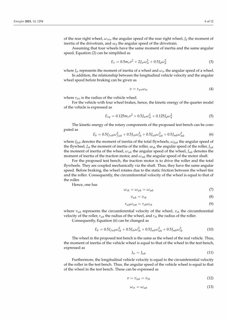
The developed control unit is shown in Figure 8, in which ⓐ is the drive/reverse switch, ⓑ the start/stop switch, ⓒ the ABS/Non-ABS switch, ⓓ the reverse indicator light, ⓔ the drive indicator light, ⓕ the start/stop indicator light, ⓖ the ABS fault indi-cator light, ⓗ the ABS operation indicator light, ⓘ the braking indicator light, ⓙ the motor speed meter, ⓚ the ABS control subunit, ⓛ the brake control subunit, and ⓜ the motor control subunit.
Figure 8. Prototype of developed control unit for proposed test bench.
5. Application
Figure 7. Block diagram of motor control subunit.
The switch subunit provides the operating instructions including the braking instruc-tion with/without ABS to the ABS control subunit, the start/stop instruction to the motorcontrol subunit, and the drive/reverse direction instruction to the motor control subunit,and displays the traction motor speed and the operating status including the brakingoperation, the ABS operation, the ABS fault, the start/stop, the drive operation, and thereverse operation.
The maximum sampling rate of 12-bit A/D converters in the ABS subunit reaches2.4 Megasamples per second (MSPS), which fully meets to acquire any analog signals in
Energies 2021, 14, 1294 10 of 12
the test bench. Consequently, the signal bandwidth of the test bench fully depends on thespeed sensor of the wheel and the relevant filter. In the developed test bench, the speedsensor of the wheel is the one in the commercial car BYD-F0 and the speed signal of themotor is from the output of the commercial motor inverter. The measurable bandwidth ofthe wheel speed is 4 Hz–2 kHz and the one related to the motor speed is 2.5 Hz–50 kHz.
The developed control unit is shown in Figure 8, in which a© is the drive/reverseswitch, b© the start/stop switch, c© the ABS/Non-ABS switch, d© the reverse indicator light,e© the drive indicator light, f© the start/stop indicator light, g© the ABS fault indicator
light, h© the ABS operation indicator light, i© the braking indicator light, j© the motorspeed meter, k© the ABS control subunit, l© the brake control subunit, and m© the motorcontrol subunit.
Energies 2021, 14, x FOR PEER REVIEW 10 of 12
The brake control subunit receives the torque signal from the ABS control subunit, outputs the fault signal to the ABS control subunit, and controls the torque magnitude and the torque direction of the brake motor. Thereby, the clamping force of the electro-mechanical brake can be changed. The schematic of the brake control subunit is illus-trated in Figure 6.
The motor control subunit receives the start/stop signal from the switch subunit, the drive/reverse signal from the switch subunit, the acceleration signal from the acceleration pedal and the motor speed signal from the motor speed sensor, controls the magnitude and direction of the traction motor speed, and implements the closed-loop speed control. Figure 7 shows the interface of the motor control subunit.
Figure 7. Block diagram of motor control subunit.
The switch subunit provides the operating instructions including the braking in-struction with/without ABS to the ABS control subunit, the start/stop instruction to the motor control subunit, and the drive/reverse direction instruction to the motor control subunit, and displays the traction motor speed and the operating status including the braking operation, the ABS operation, the ABS fault, the start/stop, the drive operation, and the reverse operation.
The maximum sampling rate of 12-bit A/D converters in the ABS subunit reaches 2.4 Megasamples per second (MSPS), which fully meets to acquire any analog signals in the test bench. Consequently, the signal bandwidth of the test bench fully depends on the speed sensor of the wheel and the relevant filter. In the developed test bench, the speed sensor of the wheel is the one in the commercial car BYD-F0 and the speed signal of the motor is from the output of the commercial motor inverter. The measurable bandwidth of the wheel speed is 4 Hz–2 kHz and the one related to the motor speed is 2.5 Hz–50 kHz.
The developed control unit is shown in Figure 8, in which ⓐ is the drive/reverse switch, ⓑ the start/stop switch, ⓒ the ABS/Non-ABS switch, ⓓ the reverse indicator light, ⓔ the drive indicator light, ⓕ the start/stop indicator light, ⓖ the ABS fault indi-cator light, ⓗ the ABS operation indicator light, ⓘ the braking indicator light, ⓙ the motor speed meter, ⓚ the ABS control subunit, ⓛ the brake control subunit, and ⓜ the motor control subunit.
Figure 8. Prototype of developed control unit for proposed test bench.
5. Application
Figure 8. Prototype of developed control unit for proposed test bench.
5. Application
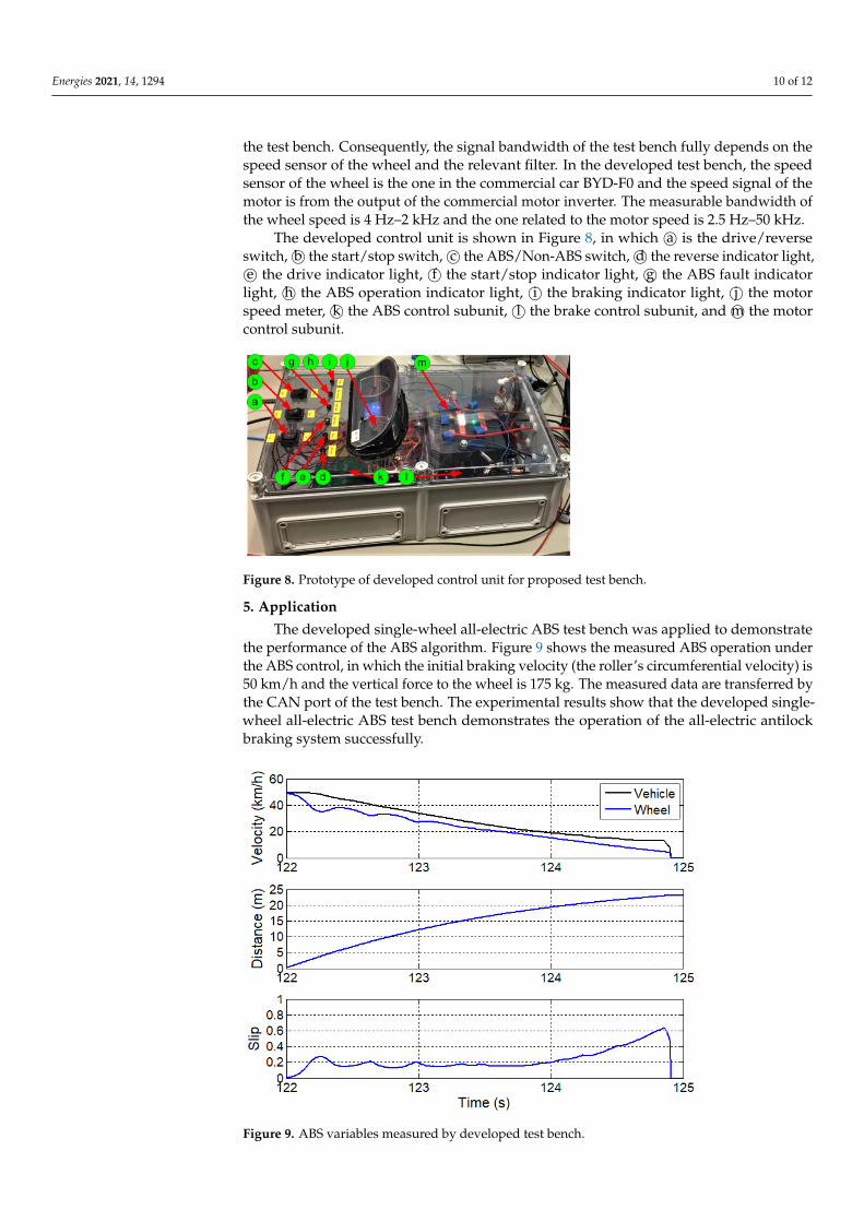
The developed single-wheel all-electric ABS test bench was applied to demonstratethe performance of the ABS algorithm. Figure 9 shows the measured ABS operation underthe ABS control, in which the initial braking velocity (the roller’s circumferential velocity) is50 km/h and the vertical force to the wheel is 175 kg. The measured data are transferred bythe CAN port of the test bench. The experimental results show that the developed single-wheel all-electric ABS test bench demonstrates the operation of the all-electric antilockbraking system successfully.
Energies 2021, 14, x FOR PEER REVIEW 11 of 12
The developed single-wheel all-electric ABS test bench was applied to demonstrate the performance of the ABS algorithm. Figure 9 shows the measured ABS operation un-der the ABS control, in which the initial braking velocity (the roller’s circumferential ve-locity) is 50 km/h and the vertical force to the wheel is 175 kg. The measured data are transferred by the CAN port of the test bench. The experimental results show that the developed single-wheel all-electric ABS test bench demonstrates the operation of the all-electric antilock braking system successfully.
Figure 9. ABS variables measured by developed test bench.
The tire-road adhesion coefficient plays a key role in ABS performance. It mainly depends on the road surfaces. Consequently, the different road surfaces result in the various adhesion coefficients. In the proposed test bench, the roller surface of the alu-minum alloy is to simulate a road condition. To obtain the various adhesion coefficients, thereby, the different degrees of the smoothness and the different materials of the roller surface should be designed. It shall be the future study.
6. Conclusions This paper proposes a technical scheme to develop the single-wheel all-electric ABS
test bench. The technology is based on the proposed model, in which the kinetic energy of the total rotary components in the bench matches the kinetic energy of a real car when braking. From the model, the design formulas of the roller and the flywheels can be de-rived. The developed single-wheel all-electric ABS test bench is able to simulate the dy-namic behavior of the real wheel of the commercial car and the operation of the all-electric ABS. It may provide the repetitive tests with the variables, such as the differ-ent braking velocities, the different vertical forces to the wheel, the different tire condi-tions, the different conditions of braking pads and disc, and the different road surfaces. It is low cost and compact, and is a prior solution to demonstrating, evaluating, and veri-fying ABS methods/algorithms in a laboratory. It can save cost and time for the subse-quent tests on ABS on real road.
Author Contributions: Methodology, system design, experiment and writing—original draft preparation, X.X.; methodology, supervision and writing—review, K.W.E.C.; mechanical design, W.W.C.; control unit, software and experiment, Y.C.F.; control unit and experiment, K.L.J.K.; and
Figure 9. ABS variables measured by developed test bench.

Energies 2021, 14, 1294 11 of 12
The tire-road adhesion coefficient plays a key role in ABS performance. It mainlydepends on the road surfaces. Consequently, the different road surfaces result in the variousadhesion coefficients. In the proposed test bench, the roller surface of the aluminum alloyis to simulate a road condition. To obtain the various adhesion coefficients, thereby, thedifferent degrees of the smoothness and the different materials of the roller surface shouldbe designed. It shall be the future study.
6. Conclusions
This paper proposes a technical scheme to develop the single-wheel all-electric ABStest bench. The technology is based on the proposed model, in which the kinetic energyof the total rotary components in the bench matches the kinetic energy of a real car whenbraking. From the model, the design formulas of the roller and the flywheels can bederived. The developed single-wheel all-electric ABS test bench is able to simulate thedynamic behavior of the real wheel of the commercial car and the operation of the all-electric ABS. It may provide the repetitive tests with the variables, such as the differentbraking velocities, the different vertical forces to the wheel, the different tire conditions,the different conditions of braking pads and disc, and the different road surfaces. It is lowcost and compact, and is a prior solution to demonstrating, evaluating, and verifying ABSmethods/algorithms in a laboratory. It can save cost and time for the subsequent tests onABS on real road.
Author Contributions: Methodology, system design, experiment and writing—original draft prepa-ration, X.X.; methodology, supervision and writing—review, K.W.E.C.; mechanical design, W.W.C.;control unit, software and experiment, Y.C.F.; control unit and experiment, K.L.J.K.; and electrome-chanical brake and mechanical design, Y.F. All authors have read and agreed to the published versionof the manuscript.
Funding: This research was funded partly by the Guangdong-Hong Kong Technology CooperationFunding Scheme of Hong Kong Innovation and Technology Support Programme, grant numberGHP/033/17AP, and university research project 845G.
Institutional Review Board Statement: Not applicable.
Informed Consent Statement: Not applicable.
Acknowledgments: The authors would like to thank S. Raghu Raman for the support in the experi-ment.
Conflicts of Interest: The authors declare no conflict of interest. The funders had no role in the designof the study; in the collection, analyses, or interpretation of data; in the writing of the manuscript, orin the decision to publish the results.
References1. Guo, J.; Jian, X.; Lin, G. Performance Evaluation of an Anti-Lock Braking System for Electric Vehicles with a Fuzzy Sliding Mode
Controller. Energies 2014, 7, 6459–6476. [CrossRef]2. Juan, A.C.; Antonio, O.; Juan, J.C.; Antonio, S. A Fuzzy Logic Control for Antilock Braking System Integrated in the IMMa Tire
Test Bench. IEEE Trans. Veh. Technol. 2005, 54, 1937–1949.3. Shim, T.; Chang, S.; Lee, S. Investigation of Sliding-Surface Design on the Performance of Sliding Mode Controller in Antilock
Braking Systems. IEEE Trans. Veh. Technol. 2008, 57, 747–759. [CrossRef]4. Patil, A.; Ginoya, D.; Shendge, P.D.; Phadke, S.B. Uncertainty-Estimation-Based Approach to Antilock Braking Systems. IEEE
Trans. Veh. Technol. 2015, 65, 1171–1185. [CrossRef]5. Sun, J.H.; Xue, X.D.; Cheng, K.W.E. Fuzzy Sliding Mode Wheel Slip Ratio Control for Smart Vehicle Anti-Lock Braking System.
Energies 2019, 12, 2501. [CrossRef]6. Hoseinnezhad, R.; Bab-Hadiashar, A. Efficient Antilock Braking by Direct Maximization of Tire–Road Frictions. IEEE Trans. Ind.
Electron. 2010, 58, 3593–3600. [CrossRef]7. Morselli, R.; Zanasi, R. Self-Tuning Control Strategy for Antilock Braking Systems. In Proceedings of the 2006 American Control
Conference, Minneapolis, MN, USA, 14–16 June 2006; pp. 5861–5866.8. Han, K.; Lee, B.; Choi, S.B. Development of an antilock brake system for electric vehicles without wheel slip and road friction
information. IEEE Trans. Veh. Technol. 2019, 68, 5506–5517. [CrossRef]

Energies 2021, 14, 1294 12 of 12
9. Sun, J.H.; Xue, X.D.; Cheng, K.W.E. Four-Wheel Anti-Lock Braking System with Robust Adaptation under Complex RoadConditions. IEEE Trans. Veh. Technol. 2021, 70, 292–302. [CrossRef]
10. Tomasikova, M.; Tropp, M.; Gajdosik, T.; Krzywonos, L.; Brumercik, F. Analysis of transport mecha-tronic system properties.Procedia Eng. 2017, 192, 881–886. [CrossRef]
11. Pugi, L.; Grasso, F.; Pratesi, M.; Cipriani, M.; Bartolomei, A. Design and preliminary performance evaluation of a four wheeledvehicle with degraded adhesion conditions. Int. J. Electr. Hybrid Veh. 2017, 9, 1–32. [CrossRef]
12. Oniz, Y.; Kayacan, E.; Kaynak, O. A Dynamic Method to Forecast the Wheel Slip for Antilock Braking System and Its ExperimentalEvaluation. IEEE Trans. Syst. Man Cybern. Part B Cybern. 2009, 39, 551–560. [CrossRef] [PubMed]
13. Khatun, P.; Bingham, C.M.; Schofield, N.; Mellor, P.H. An Experimental Laboratory Bench Setup to Study Electric Vehicle AntilockBraking/Traction Systems and their Control. In Proceedings of the IEEE 56th Vehicular Technology Conference, Vancouver, BC,Candad, 24–28 September 2002; Volume 3, pp. 1490–1494.
14. Horn, M.; Zehetner, J. A Brake-Testbench for Research and Education. In Proceedings of the 16th IEEE International Conferenceon Control Applications, Singapore, 1–3 October 2007; pp. 444–448.
15. Huang, D.; Shen, J. Study on Mathematical Model of Test Bench for Vehicle Anti-Lock Braking System. In Proceedings of the 2009Second International Conference on Intelligent Computation Technology and Automation, Changsha, China, 10–11 October 2009;pp. 268–270.
16. Wang, R.; Wang, B.; Sun, H. Development of a Single wheel Test Bench for Anti-lock Brake System. In Proceedings of the 2010International Conference on Optoelectronics and Image Processing, Hainan, China, 11–12 November 2010; pp. 429–431.
17. Hao, R.; Zhao, X.; Xu, Z. Auto Anti-lock Braking System Bench Test Results Classification Model Based on Neural Network.In Proceedings of the 2011 International Conference on Electronics, Communications and Control (ICECC), Ningbo, China,9–11 September 2011; pp. 758–761.
18. Zhang, Z.; Cheung, N.C.; Cheng, K.W.E.; Xue, X.D.; Lin, J.K. Longitudinal and Transversal End-Effects Analysis of LinearSwitched Reluctance Motor. IEEE Trans. Ind. Electron. 2019, 67, 3990–4001. [CrossRef]
19. Tavernini, D.; Vacca, F.; Metzler, M.; Savitski, D.; Ivanov, V.; Gruber, P.; Hartavi, A.E.; Dhaens, M.; Sorniotti, A. An explicitnonlinear model predictive ABS controller for electro-hydraulic braking systems. IEEE Trans. Ind. Electron. 2020, 67, 3990–4001.[CrossRef]
20. Reif, K. Brakes, Brake Control and Driver Assistance Systems: Function, Regulation and Components; Springer Fachmedien Wiesbaden:Hessen, Deutschland, 2014; pp. 22–23.